Manual de usuario - Soler & Palau
Manual de usuario - Soler & Palau
Manual de usuario - Soler & Palau

Create successful ePaper yourself
Turn your PDF publications into a flip-book with our unique Google optimized e-Paper software.
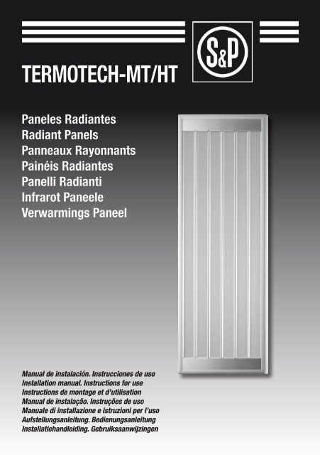
TERMOTECH-MT/HT<br />
Paneles Radiantes<br />
Radiant Panels<br />
Panneaux Rayonnants<br />
Painéis Radiantes<br />
Panelli Radianti<br />
Infrarot Paneele<br />
Verwarmings Paneel<br />
<strong>Manual</strong> <strong>de</strong> instalación. Instrucciones <strong>de</strong> uso<br />
Installation manual. Instructions for use<br />
Instructions <strong>de</strong> montage et d’utilisation<br />
<strong>Manual</strong> <strong>de</strong> instalação. Instruções <strong>de</strong> uso<br />
<strong>Manual</strong>e di installazione e istruzioni per l’uso<br />
Aufstellungsanleitung. Bedienungsanleitung<br />
Installatiehandleiding. Gebruiksaanwijzingen<br />
1
1<br />
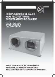
Ca<strong>de</strong>nas no incluidas<br />
Chain supports not inclu<strong>de</strong>d<br />
Chaines non inclues<br />
Correntes não incluídas<br />
Catena non inclusa<br />
Ketten nicht inbegriffen<br />
Kettingen niet inbegrepen<br />
ver TAB 1<br />
look at TAB 1<br />
voir TAB 1<br />
ver TAB 1<br />
ve<strong>de</strong>re TAB 1<br />
sehen TAB 1<br />
zie TAB 1<br />
2<br />
mo<strong>de</strong>lo / mo<strong>de</strong>l / modèle<br />
mo<strong>de</strong>lo / mo<strong>de</strong>llo<br />
mo<strong>de</strong>ll / mo<strong>de</strong>l<br />
a<br />
(mm)<br />
b<br />
(mm)<br />
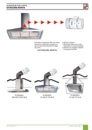
TERMOTECH HT-1750 208,50 min 1200<br />
TERMOTECH MT-1400 y<br />
TERMOTECH HT-3500<br />
378,50 min 1200<br />
TERMOTECH HT-5250 548,50 min 1200<br />
2
mo<strong>de</strong>lo<br />
mo<strong>de</strong>l<br />
modèle<br />
mo<strong>de</strong>lo<br />
mo<strong>de</strong>llo<br />
mo<strong>de</strong>ll<br />
mo<strong>de</strong>l<br />
tensión<br />
voltage<br />
tension<br />
tensão<br />
tensione<br />
spannung<br />
spanning<br />
(50Hz)<br />
TERMOTECH MT-1400 230V~ mono /<br />
400 V3~N<br />
potencia<br />
power<br />
puissance<br />
potência<br />
potenza<br />
leistung<br />
vermogen<br />
(+5% -10%)<br />
temperatura<br />
temperature<br />
température<br />
temperatura<br />
temperatura<br />
temperatur<br />
temperatuur<br />
TAB 1<br />
intensidad<br />
current<br />
intensité<br />
corrente<br />
intensità<br />
strom<br />
stroom<br />
(max)<br />
(A)<br />
TAB 2<br />
protección<br />
protection<br />
protection<br />
proteção<br />
protezione<br />
schutz<br />
bescherming<br />
aislamiento<br />
electrical insulation<br />
isolation électrique<br />
isolamento elétrico<br />
isolamento elettrico<br />
elektrische Isolation<br />
elektrische isolatie<br />
altura recomendada<br />
reccomen<strong>de</strong>d height<br />
hauteur recommandée<br />
altura recomendada<br />
altezza consigliata<br />
empfohlenen höhe<br />
aanbevolen hoogte<br />
conexión<br />
connection<br />
raccor<strong>de</strong>ment<br />
conexão<br />
connessione<br />
verbindung<br />
schema<br />
( TAB 2)<br />
peso<br />
weight<br />
poids<br />
peso<br />
peso<br />
gewicht<br />
gewicht<br />
(W) (°C) 230 V 400 V (m) (kg)<br />
1.400 150 6,4 3,7 IP54 Clase I 2,5 a 3,5 B-C 11<br />
TERMOTECH HT-1750 230V~ mono 1.750 300 7,7 5,5 IP54 Clase I 3,5 a 4,5 A 8<br />
TERMOTECH HT-3500 230V~ mono /<br />
400 V3~N<br />
TERMOTECH HT-5250 230V~ mono /<br />
400 V3~N<br />
3.500 300 16,0 9,3 IP54 Clase I 3,5 a 7,5 B-C 12<br />
5.250 300 24,0 13,5 IP54 Clase I 3,5 a 7,5 D-E 16<br />
3
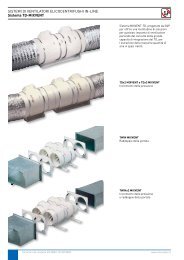
TAB 3<br />
Diámetro <strong>de</strong>l cable<br />
Cable diameter<br />
Diamètre du câble<br />
Diâmetro do cabo<br />
Diametro <strong>de</strong>l cavo<br />
Kabeldurchmesser<br />
Kabeldoorsne<strong>de</strong><br />
(mm)<br />
MIN. IP54<br />
Ø agujero<br />
Ø orifice<br />
Ø trou<br />
Ø furo<br />
6 7 8 9 10 11 12 13 14<br />
Ø foro<br />
Ø loch<br />
Ø gat<br />
(mm)<br />
M20 20<br />
M16 16<br />
PG21 29<br />
PG16 23<br />
PG13,5 21<br />
PG11 19<br />
PG9 16<br />
GAS ¾” 29<br />
GAS 5 /8” 23<br />
GAS ½” 21<br />
GAS 3 /8” 16<br />
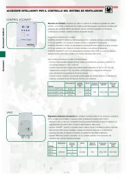
3<br />
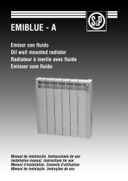
ATENCIÓN: NO PONER LOS CABLES DENTRO DEL PRODUCTO<br />
ATTENTION: DO NOT PUSH THE CABLES INTO THE PRODUCT<br />
ATTENTION: NE PAS METTRE LES CABLES À L’INTÉRIEUR DE L’APPAREIL<br />
ATENÇÃO: NÃO COLOCAR OS CABOS DENTRO DO PRODUTO<br />
ATTENZIONE: NON SPINGERE I CAVI DENTRO AL PRODOTTO<br />
VORSICHT: DIE KABEL DÜRFEN NICHT INNERHALB DES GERÄTES VERSCHOBEN WERDEN<br />
OPGELET: STOP DE KABELS NIET IN HET PRODUCT<br />
4
ESPAÑOL<br />
Es preciso leer atentamente estas instrucciones antes <strong>de</strong> utilizar el producto, con<br />
el fin <strong>de</strong> evitar averías o situaciones <strong>de</strong> peligro. Cualquier uso <strong>de</strong>l aparato que no<br />
siga las indicaciones <strong>de</strong>l presente manual pue<strong>de</strong> causar incendios, peligros <strong>de</strong> tipo<br />
eléctrico o lesiones, y anula toda garantía.<br />
ESPAÑOL<br />
La garantía no se aplica a ningún <strong>de</strong>fecto, <strong>de</strong>terioro, pérdida, lesión o daño <strong>de</strong>bidos a un uso<br />
incorrecto <strong>de</strong>l producto. Ninguna condición <strong>de</strong> la garantía pue<strong>de</strong> excluir o modificar las condiciones<br />
previstas por las leyes estatales, que no se pue<strong>de</strong>n excluir o modificar bajo ningún<br />
concepto.<br />
Antes <strong>de</strong> cualquier operación, retire cuidadosamente el embalaje y compruebe la integridad<br />
<strong>de</strong>l producto. En caso <strong>de</strong> que se encontraran <strong>de</strong>fectos o daños, no lo instale ni intente repararlo:<br />
póngase en contacto con el distribuidor.<br />
No <strong>de</strong>je el embalaje al alcance <strong>de</strong> los niños y elimine las piezas según las disposiciones vigentes.<br />
1. PARA SU SEGURIDAD<br />
• Asegúrese <strong>de</strong> que la fuente la alimentación sea la a<strong>de</strong>cuada, según los datos <strong>de</strong> la placa.<br />
• Nunca <strong>de</strong>je que niños o mascotas jueguen con el producto o lo toquen. ¡Atención! Durante<br />
el funcionamiento, el panel pue<strong>de</strong> llegar a alcanzar altas temperaturas (alre<strong>de</strong>dor <strong>de</strong><br />
160°C/320°F en las versiones MT y 320°C/608°F en las HT).<br />
• IMPORTANTE: para evitar sobrecalentamientos, no cubra nunca el producto. No<br />
apoye ningún objeto en el aparato.<br />
• Este producto no lo <strong>de</strong>ben utilizar personas (niños incluidos) con capacida<strong>de</strong>s físicas, sensoriales<br />
o mentales reducidas, o con experiencia y conocimientos ina<strong>de</strong>cuados, si no están<br />
bajo la supervisión <strong>de</strong> una persona responsable <strong>de</strong> su seguridad o si dicha persona no les<br />
ha instruido a<strong>de</strong>cuadamente. Los niños <strong>de</strong>ben ser vigilados para asegurarse <strong>de</strong> que no<br />
jueguen con el producto.<br />
• El producto no está equipado con ningún dispositivo <strong>de</strong> control <strong>de</strong> la temperatura ambiente.<br />
No utilice el panel calefactor en ambientes <strong>de</strong> pequeñas dimensiones si en éstos se<br />
encuentran personas (niños incluidos) que no puedan irse <strong>de</strong> la habitación solos y que no<br />
estén bajo constante supervisión <strong>de</strong> una persona responsable <strong>de</strong> su seguridad.<br />
• Nunca utilice el producto en estancias don<strong>de</strong> haya ambientes saturados <strong>de</strong> gases o vapores<br />
inflamables, explosivos, <strong>de</strong> disolventes o pinturas.<br />
• El producto se <strong>de</strong>be colocar <strong>de</strong> tal manera que la fuente <strong>de</strong> alimentación sea siempre accesible.<br />
5
2. UBICACIÓN SEGURA<br />
ESPAÑOL<br />
• Utilice el producto exclusivamente en posición horizontal con la superficie calefactora vuelta<br />
hacia abajo.<br />
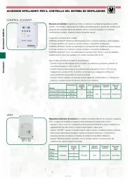
• El aparato calefactor no <strong>de</strong>be ser colocado justo <strong>de</strong>bajo <strong>de</strong> una toma <strong>de</strong> corriente y no se <strong>de</strong>be<br />
instalar en el interior <strong>de</strong> un hueco. La posición a<strong>de</strong>cuada es suspendida, <strong>de</strong>jando al menos<br />
15 cm <strong>de</strong> espacio entre su parte posterior y el techo, y 180 cm entre el producto y el suelo.<br />
• La superficie radiante frontal <strong>de</strong>l panel <strong>de</strong>be quedar libre, sin objetos, que podrían restarle<br />
eficacia, dañarlo o estropearlo irreparablemente y provocar riesgo <strong>de</strong> incendio. Deje al menos<br />
1 metro <strong>de</strong> distancia entre la superficie <strong>de</strong>l panel y posibles objetos que se encuentren<br />
directamente por <strong>de</strong>bajo <strong>de</strong>l mismo. A<strong>de</strong>más, <strong>de</strong>be colocarse a una distancia mínima <strong>de</strong><br />
50 cm <strong>de</strong> las pare<strong>de</strong>s laterales.<br />
• El producto está fabricado con aislamiento eléctrico simple (Clase I) y, por lo tanto, requiere<br />
conexión a tierra.<br />
• Respete siempre las distancias mínimas a las pare<strong>de</strong>s, al techo y al suelo <strong>de</strong>scritas en la<br />
figura 1.<br />
• No instale nunca el producto en contacto con superficies <strong>de</strong> ma<strong>de</strong>ra o <strong>de</strong> material sintético.<br />
• El producto tiene un grado IP54 <strong>de</strong> protección contra la suciedad y el agua.<br />
3. INSTALACIÓN<br />
• Después <strong>de</strong> haber leído atentamente las advertencias <strong>de</strong> seguridad <strong>de</strong> los párrafos prece<strong>de</strong>ntes,<br />
sujete el producto utilizando 4 ca<strong>de</strong>nas metálicas <strong>de</strong> características a<strong>de</strong>cuadas a su peso.<br />
• En el interior <strong>de</strong>l embalaje hay un sobre con 4 ganchos <strong>de</strong> ojal para su instalación (figura 2):<br />
– Atornille, sin apretar excesivamente, los 4 ganchos a las tuercas <strong>de</strong>l interior <strong>de</strong>l marco<br />
posterior <strong>de</strong>l producto.<br />
– Haga <strong>de</strong>slizar los ganchos hasta la posición más a<strong>de</strong>cuada, respetando las limitaciones<br />
que figuran en la tabla <strong>de</strong> la figura 2.<br />
– Apriete con fuerza los ganchos hasta fijarlos en la posición escogida.<br />
• I<strong>de</strong>ntifique los 4 puntos en los que sujetar las ca<strong>de</strong>nas, respetando las distancias mínimas<br />
indicadas en la figura 1.<br />
• Coloque las 4 ca<strong>de</strong>nas en los puntos escogidos utilizando tacos u otros sistemas a<strong>de</strong>cuados<br />
al peso <strong>de</strong>l producto y a la tipología <strong>de</strong>l soporte en el cual se <strong>de</strong>sea efectuar el anclaje.<br />
• Colgar el producto <strong>de</strong> las ca<strong>de</strong>nas utilizando elementos <strong>de</strong> conexión a<strong>de</strong>cuados.<br />
4. CONEXIÓN A LA RED ELÉCTRICA<br />
• Antes <strong>de</strong> realizar cualquier operación, recuer<strong>de</strong> <strong>de</strong>sconectar la red <strong>de</strong> suministro <strong>de</strong> energía<br />
y asegúrese <strong>de</strong> que no pueda ser restablecida acci<strong>de</strong>ntalmente.<br />
• Todos los productos <strong>de</strong> la gama <strong>de</strong>ben ser instalados y utilizados por personas con la <strong>de</strong>bida<br />
calificación y preparación.<br />
• Deben ser instalados <strong>de</strong> acuerdo con las normativas en vigor en el país y a las especificaciones<br />
<strong>de</strong> este manual. Antes <strong>de</strong> instalar el aparato, asegúrese <strong>de</strong> que las características<br />
6
<strong>de</strong> la red sean a<strong>de</strong>cuadas a las especificaciones <strong>de</strong> alimentación requeridas. La conexión<br />
eléctrica a la red <strong>de</strong>be incluir, a<strong>de</strong>más, el uso <strong>de</strong> un interruptor multiswitch con una distancia<br />
mínima <strong>de</strong> apertura entre los contactos <strong>de</strong> al menos 3 mm.<br />
• La gama incluye varios mo<strong>de</strong>los, diferenciados o por el número <strong>de</strong> elementos calefactores<br />
o por la potencia consumida. Para que la instalación sea lo más flexible y compatible<br />
posible con las características <strong>de</strong> su sistema, todos los productos están dotados <strong>de</strong> una<br />
caja <strong>de</strong> conexiones externa. Dentro <strong>de</strong> la caja hay un borne multipin para la conexión <strong>de</strong>l<br />
conector a tierra, <strong>de</strong>l neutro y <strong>de</strong> las fases.<br />
• Para los productos con 2 ó 3 resistencias, todas las fases se ponen a disposición <strong>de</strong>l borne<br />
<strong>de</strong> forma in<strong>de</strong>pendiente para que sea posible:<br />
– Realizar circuitos <strong>de</strong> alimentación que permitan activar separadamente los elementos<br />
calefactores <strong>de</strong> uno en uno, lo que posibilita la reducción <strong>de</strong>l consumo total <strong>de</strong> energía<br />
en los períodos en que se necesita menos calefacción.<br />
– Conectar el producto a una red trifásica distribuyendo las cargas entre las distintas fases<br />
para equilibrar óptimamente el sistema.<br />
• Para una instalación y conexión a la red eléctrica correctas es necesario:<br />
1. Optar por una conexión monofásica o trifásica, según los esquemas indicados en la<br />
tabla TAB 2 y, consecuentemente, <strong>de</strong>terminar la cantidad <strong>de</strong> conductores necesarios.<br />
2. Respetar la sección mínima <strong>de</strong> los conductores especificada en el REBT.<br />
3. Optar por una conexión mediante un cable <strong>de</strong> alimentación o por medio <strong>de</strong> un tubo<br />
(rígido o flexible) y escoger el dispositivo <strong>de</strong> sujeción <strong>de</strong> cables o la junta <strong>de</strong> empalme<br />
a<strong>de</strong>cuados (grado <strong>de</strong> protección mínimo IP54).<br />
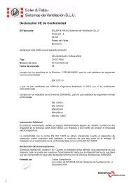
4. Abrir la caja <strong>de</strong> conexiones (figura 3/a) para perforarla en el punto pre<strong>de</strong>finido (figura<br />
3/b) y fijar el dispositivo <strong>de</strong> sujeción <strong>de</strong> cables o la junta <strong>de</strong> empalme (figura 3/c-d). El<br />
diámetro <strong>de</strong>l orificio a realizar en la caja <strong>de</strong> conexiones varía en función <strong>de</strong>l dispositivo<br />
<strong>de</strong> sujeción <strong>de</strong> cables o <strong>de</strong> la junta escogidos y hay que realizarlo en el lado superior <strong>de</strong><br />
la caja en correspon<strong>de</strong>ncia con el punto preimpreso.<br />
5. Efectuar las conexiones eléctricas necesarias (figura 3/e-f), teniendo en cuenta <strong>de</strong> no<br />
pelar los cables más <strong>de</strong> 8 mm para no correr el riesgo <strong>de</strong> que entren en contacto con<br />
otros conductores. No atornillar el borne en el aislante.<br />
6. Apretar a<strong>de</strong>cuadamente el dispositivo <strong>de</strong> sujeción <strong>de</strong> cables o la junta <strong>de</strong> conexión<br />
(figura 3/g).<br />
7. Cerrar la caja <strong>de</strong> conexiones con los tornillos suministrados (figura 3/h).<br />
• Si se ha escogido usar un cable <strong>de</strong> alimentación <strong>de</strong>be:<br />
– Seleccionar uno <strong>de</strong>l tipo H05RN-F o FROR 450/750V.<br />
– I<strong>de</strong>ntificar el dispositivo <strong>de</strong> sujeción <strong>de</strong> cables más a<strong>de</strong>cuado en función <strong>de</strong>l diámetro <strong>de</strong>l<br />
cable utilizando la tabla TAB 3.<br />
– Cuidar <strong>de</strong> que el cable, una vez conectado, no pueda entrar nunca en contacto con las<br />
partes metálicas <strong>de</strong>l producto.<br />
ESPAÑOL<br />
Ejemplo:<br />
Se ha adquirido el producto TERMOTECH HT-5250 y se <strong>de</strong>sea utilizar el cable para la conexión<br />
a una red trifásica. Teniendo en cuenta estas condiciones <strong>de</strong>bemos:<br />
1. I<strong>de</strong>ntificar la cantidad <strong>de</strong> conductores necesarios: hemos escogido la conexión tipo “E”<br />
(red trifásica): luego, habrá 5 conductores a tierra, N, L1, L2 y L3.<br />
2. Verificar la sección mínima <strong>de</strong> los conductores según el REBT.<br />
3. Escoger el tipo <strong>de</strong> cable que queremos utilizar: por ejemplo, el FROR 450/750V 5G2,5<br />
(con conector amarillo/ver<strong>de</strong> para la conexión a tierra) satisface todos los requisitos.<br />
7
ESPAÑOL<br />
4. Determinar el diámetro exterior <strong>de</strong>l cable escogido: 12,4 mm.<br />
5. I<strong>de</strong>ntificar, usando la tabla TAB 3, el tipo <strong>de</strong> dispositivo <strong>de</strong> sujeción <strong>de</strong> cables a<strong>de</strong>cuado<br />
para el diámetro 12,4 mm: se pue<strong>de</strong>n escoger los <strong>de</strong> enroscado M20, PG16 E GAS ⅝”.<br />
Seleccionamos el PG16.<br />
6. Verificar el diámetro <strong>de</strong>l orificio que <strong>de</strong>bemos hacer en la caja <strong>de</strong> conexiones en función<br />
<strong>de</strong>l dispositivo <strong>de</strong> sujeción <strong>de</strong> cables escogido utilizando la tabla TAB 3: para el PG16<br />
el diámetro <strong>de</strong>l agujero <strong>de</strong>be ser <strong>de</strong> 23 mm.<br />
7. Perforar la caja en el punto pre<strong>de</strong>finido realizando una apertura que tenga el mismo<br />
diámetro <strong>de</strong>l punto prece<strong>de</strong>nte (figura 3/a-b).<br />
8. Fijar el dispositivo <strong>de</strong> sujeción <strong>de</strong> cables a la caja <strong>de</strong> conexiones utilizando la tuerca<br />
suministrada (figura 3/c-d).<br />
9. Insertar el cable en el dispositivo y efectuar las conexiones eléctricas (figura 3/e-f).<br />
10. Apretar el dispositivo (figura 3/g).<br />
11. Cerrar la caja <strong>de</strong> conexiones con los 4 tornillos suministrados (figura 3/h).<br />
5. UTILIZACIÓN DEL PRODUCTO<br />
• El producto no está equipado con ningún interruptor o dispositivo <strong>de</strong> control <strong>de</strong> la temperatura<br />
y <strong>de</strong>be ser regulado mediante dispositivos apropiados que hay que prever en la fase<br />
<strong>de</strong> construcción <strong>de</strong> la planta (por ej., interruptores diferenciales e interruptores magnetotérmicos).<br />
• En las versiones con 2 ó 3 resistencias se indica la posibilidad <strong>de</strong> crear diferentes circuitos<br />
<strong>de</strong> alimentación para que sea posible activar sólo parcialmente el producto en todas las<br />
situaciones en que se requiera menos calefacción. En las versiones con 3 resistencias, por<br />
ejemplo, se aconseja realizar un circuito para la alimentación <strong>de</strong>l elemento central (fase L2)<br />
y otro para la <strong>de</strong> los elementos laterales (fases L1 y L3) con el fin <strong>de</strong> que sea posible aprovechar,<br />
según las necesida<strong>de</strong>s, 1/3, 2/3 ó 3/3 <strong>de</strong> la potencia disponible.<br />
• ¡Atención!: en las primeras horas <strong>de</strong> funcionamiento <strong>de</strong>spués <strong>de</strong> la primera instalación es<br />
posible que el producto emita un olor <strong>de</strong>sagradable y/o un poco <strong>de</strong> humo. Ello es <strong>de</strong>bido<br />
a la posible presencia <strong>de</strong> residuos <strong>de</strong> alguna sustancia utilizada durante el proceso <strong>de</strong> producción<br />
y no es signo <strong>de</strong> ningún <strong>de</strong>fecto, ningún mal funcionamiento <strong>de</strong>l producto ni <strong>de</strong> un<br />
peligro para la seguridad y la salud <strong>de</strong> los <strong>usuario</strong>s.<br />
6. MANTENIMIENTO<br />
• Este producto no requiere mantenimiento especial.<br />
• Se recomienda verificar que el aparato está frío y que la alimentación <strong>de</strong> la red está <strong>de</strong>sconectada<br />
antes <strong>de</strong> efectuar cualquier intervención.<br />
• En caso <strong>de</strong> que sea necesario repararlo, póngase en contacto con un Servicio <strong>de</strong> Asistencia<br />
Técnica autorizado.<br />
8
ENGLISH<br />
Please read these instructions carefully before using the product, to avoid breakdowns<br />
or dangerous situations. Any use of this appliance that does not follow the<br />
instructions contained in this manual could cause fires, electrical hazards or injury<br />
and will ren<strong>de</strong>r the guarantee void.<br />
The guarantee does not cover any <strong>de</strong>fect, damage, loss or harm caused by misuse of the<br />
product. No condition in the guarantee can exclu<strong>de</strong> or modify the conditions established in<br />
State legislation, which cannot be exclu<strong>de</strong>d or modified un<strong>de</strong>r any circumstance.<br />
ENGLISH<br />
Before any operation, remove the packaging carefully and check the state of the product. If<br />
any <strong>de</strong>fect or damage is found, do not install it or try to repair it: please contact the distributor.<br />
Do not leave the packaging within reach of children and dispose of packing materials according<br />
to current regulations.<br />
1. FOR YOUR SAFETY<br />
• Make sure the power supply is a<strong>de</strong>quate for the inten<strong>de</strong>d use, according to the specifications<br />
plate.<br />
• Never let children or pets play with the product or touch it. Attention! During operation,<br />
the panel can get very hot (around 160°C/320°F in MT mo<strong>de</strong>ls and 320°C/608°F in HT<br />
mo<strong>de</strong>ls).<br />
• IMPORTANT: To avoid overheating, never cover the appliance. Do not lean any<br />
object on the appliance.<br />
• This product should not be used by people (including children) with reduced physical, sensory<br />
or mental capacity or people with ina<strong>de</strong>quate experience and knowledge, unless they<br />
are un<strong>de</strong>r the supervision of a person responsible for their safety or this person has instructed<br />
them a<strong>de</strong>quately. Children should be monitored to ensure that they do not play with the<br />
product.<br />
• The product has no <strong>de</strong>vice to control ambient temperature. Do not use the heating panel in<br />
environments of reduced space if there are people (including children) in it who cannot leave<br />
the room alone and who are not un<strong>de</strong>r constant supervision of a person in charge of their<br />
safety.<br />
• Never use the product in rooms containing concentrations of inflammable vapours or gases,<br />
explosives, solvents or paint.<br />
• The product must be placed in such a manner that the power source is always accessible.<br />
9
2. SAFE LOCATION<br />
ENGLISH<br />
• Only use the product in horizontal position with the heating surface facing downwards.<br />
• The heating <strong>de</strong>vice must not be placed immediately un<strong>de</strong>r a power point and should not be<br />
installed in a hollow space. The correct position is suspen<strong>de</strong>d, leaving at least 15 cm space<br />
between the rear and the ceiling and 180 cm between the product and the floor.<br />
• The front radiating surface of the panel should be free, unobstructed by objects that could<br />
reduce its efficacy or damage it irreparably as well as causing a fire hazard. Leave at least<br />
1-metre between the surface of the panel and possible objects directly un<strong>de</strong>rneath it. In<br />
addition, it must be placed at least 50 cm from si<strong>de</strong> walls.<br />
• The product is manufactured with simple electrical insulation (Class I) and therefore requires<br />
an earth connection.<br />
• Always respect the minimum distances from walls, ceiling and floor as <strong>de</strong>scribed in Fig. 1.<br />
• Never install the product in contact with woo<strong>de</strong>n or synthetic material surfaces.<br />
• This product has gra<strong>de</strong> IP54 protection against dirt and water.<br />
3. INSTALLATION<br />
• After carefully reading the safety warnings in the above paragraphs, secure the product using<br />
4 metal chains of characteristics a<strong>de</strong>quate to its weight.<br />
• Insi<strong>de</strong> the packaging there is an envelope with 4 eyehooks for installation (Fig. 2):<br />
– Screw the 4 eyehooks into the nuts on the interior of the rear frame of the product (Do not<br />
tighten them excessively).<br />
– Sli<strong>de</strong> the hooks to the best position, respecting the limitations expressed in the table in<br />
Fig. 2.<br />
– Tighten the hooks firmly until they are secured in the <strong>de</strong>sired position.<br />
• I<strong>de</strong>ntify the 4 points where the chains are to be secured, respecting the minimum distances<br />
indicated in Fig. 1.<br />
• Place the 4 chains in the chosen points using raw plugs or other anchoring systems a<strong>de</strong>quate<br />
for the weight of the product and the type of support you wish to use for anchoring.<br />
• Hang the product from the chains using a<strong>de</strong>quate securing elements.<br />
4. CONNECTING TO THE ELECTRICITY SUPPLY<br />
• Before carrying out any operation, remember to disconnect the power supply and make<br />
sure that it cannot be reconnected acci<strong>de</strong>ntally.<br />
• All products in this range must be installed and used by people with sufficient qualifications<br />
and training.<br />
• The appliance must be installed in compliance with national regulations as well as the specifications<br />
<strong>de</strong>tailed in this manual. Before installing the appliance, make sure the electricity<br />
supply is suitable for the specifications of the appliance. Electrical connection to the mains<br />
must also inclu<strong>de</strong> the use of a multiswitch with a gap of at least 3 mm between contacts.<br />
10
• This range inclu<strong>de</strong>s several mo<strong>de</strong>ls, differentiated by the number of heating elements or<br />
their power consumption. To make the installation as flexible and compatible as possible<br />
with your requirements, all the products have an external connection box. Insi<strong>de</strong> the box<br />
there is a multipin terminal strip for connecting ground, neutral and phases cables.<br />
• For products with 2 or 3 resistances, all the phases are at the disposal of the terminal in<strong>de</strong>pen<strong>de</strong>ntly,<br />
so that it is possible:<br />
– To <strong>de</strong>sign power supply circuits enabling separate activation of the heating elements one<br />
by one, enabling reduction of total energy consumption when less heating is nee<strong>de</strong>d.<br />
– Connect the product to a three-phase electricity supply, distributing the loads between<br />
the different phases to balance the system in an optimum manner.<br />
• For correct installation and connection to the mains, it is necessary to:<br />
1. Opt for a single-phase or three-phase connection, according to the diagrams indicated<br />
in table TAB 2 and then <strong>de</strong>termine the amount of conductors nee<strong>de</strong>d.<br />
2. Respect the minimum section of conductors.<br />
3. You can choose a connection via a power cable or via a tube (rigid or flexible) and<br />
choose the <strong>de</strong>vice to hold the cables or an a<strong>de</strong>quate connection joint (Minimum <strong>de</strong>gree<br />
of protection: IP54).<br />
4. Open the connection box (Fig. 3/a) to perforate it in the pre<strong>de</strong>fined point (Fig. 3/b) and<br />
secure the <strong>de</strong>vice for holding the cables or connection joint (Fig. 3/c-d). The diameter<br />
of the orifice to be ma<strong>de</strong> in the connection box will vary according to the <strong>de</strong>vice used<br />
for holding the cable gland seal chosen and it must be ma<strong>de</strong> at the top of the box, corresponding<br />
to the pre<strong>de</strong>termined point.<br />
5. Make the necessary electrical connections (Fig. 3/e-f), stripping the cables no more than<br />
8 mm, so as not to run the risk of them coming into contact with other cables. Do not<br />
screw the terminal to the insulation.<br />
6. Tighten the cable-holding <strong>de</strong>vice or connection joint a<strong>de</strong>quately (Fig. 3/g).<br />
7. Close the connection box with the screws supplied (Fig. 3/h).<br />
• If you have chosen to use a power cable, you should:<br />
– Select one of the H05RN-F or FROR 450/750V type.<br />
– I<strong>de</strong>ntify the most a<strong>de</strong>quate cable gland according to cable diameter, using table TAB 3.<br />
– Ensure that the cable, when connected, cannot come into contact with any metal parts of<br />
the product.<br />
ENGLISH<br />
Example:<br />
You have purchased the TERMOTECH HT-5250 and wish to use a power cable for a threephase<br />
connection. Hence, you’ll have to:<br />
1. I<strong>de</strong>ntify the necessary number of conductors: you choose connection type “E” (threephase),<br />
so you’ll get 5 conductors for earth, neutral, L1, L2 and L3.<br />
2. Verify the minimum section diameter of the conductors as indicated in TAB 2: 2,5 mm 2<br />
in this case.<br />
3. Choose which type of wire you wish to use: type FROR 450/750V 5G2,5 (yellow/green<br />
connector for earth) is necessary for the required needs.<br />
4. Verify the exterior diameter of the wire by measuring or contacting the supplier: section<br />
of the wire in this case is 12,4 mm.<br />
5. I<strong>de</strong>ntify the strain relief, according to TAB 3: for 12,4 diameter wire you could choose<br />
among strain relief with different threads: M20, PG16 and GAS ⅝”. We choose<br />
PG16.<br />
11
6. Verify the hole diameter you will have to drill on the connection box according to the<br />
strain relief you wish to use, according to TAB 3: for PG 16, hole diameter is 23 mm.<br />
7. Drill the connection box on the marked spot with a hole diameter according to the previous<br />
point (Fig. 3/a-b).<br />
8. Fix the strain relief to the connection box with the right nut (Fig. 3/c-d).<br />
9. Insert the cable through the strain relief and connect the power wires (Fig. 3/e-f).<br />
10. Tighten the strain relief (Fig. 3/g).<br />
11. Lock the connection box with 4 proper screws (Fig. 3/h).<br />
ENGLISH<br />
5. USE OF THE PRODUCT<br />
• This product is not supplied with any switch or <strong>de</strong>vice for controlling temperature and must<br />
be regulated by appropriate <strong>de</strong>vices that should be contemplated in the plant construction<br />
phase (E.g. differential switches and circuit breakers).<br />
• In versions with 2 or 3 resistances there is the possibility of <strong>de</strong>signing different power supply<br />
circuits, so it is possible to activate the product partially when less heating is nee<strong>de</strong>d. In the<br />
versions with 3 resistances, for example, it is recommen<strong>de</strong>d to have a circuit supplying the<br />
central element (Phase L2) and another for the si<strong>de</strong> elements (Phases L1 and L3) so it is<br />
possible to use 1/3, 2/3 or 3/3 of the available power, as nee<strong>de</strong>d.<br />
• Attention! After the initial installation and during the first few hours of operation, the product<br />
may give off an unpleasant smell and/or a small amount of fumes. This is caused by the<br />
presence of traces of substances used in the production process and it is not a <strong>de</strong>fect or<br />
product malfunction nor does it pose any danger to the safety and health of users.<br />
6. MAINTENANCE<br />
• This product requires no special maintenance.<br />
• It is recommen<strong>de</strong>d to check that the <strong>de</strong>vice is cold and disconnected from the power supply<br />
before any intervention.<br />
• If the appliance needs repairing, please contact an authorised Technical Service.<br />
12
FRANÇAIS<br />
Il est très important <strong>de</strong> lire attentivement ces instructions avant d’utiliser le produit<br />
afin d’éviter toute panne ou situation dangereuse. Toute utilisation autre que celles<br />
décrites dans cette notice peut provoquer <strong>de</strong>s incendies, <strong>de</strong>s risques <strong>de</strong> danger<br />
électrique ou <strong>de</strong>s lésions et annule la garantie.<br />
La garantie ne s’applique pas en cas <strong>de</strong> défaut, perte, détérioration, lésion ou dommage<br />
causés en raison d’un usage impropre <strong>de</strong> l’appareil. Aucune disposition <strong>de</strong> la présente garantie<br />
ne peut avoir pour effet d’exclure quelque garantie ou droit reconnu d’ordre public par<br />
la législation <strong>de</strong> votre pays.<br />
Avant toute opération, retirer avec précaution l’emballage et vérifier que l’appareil n’est pas<br />
endommagé. En cas <strong>de</strong> défaut ou <strong>de</strong> dommage sur l’appareil, ne pas l’installer et ne pas<br />
essayer <strong>de</strong> le réparer soi même: contacter son reven<strong>de</strong>ur.<br />
FRANÇAIS<br />
Ne pas laisser l’emballage à la portée <strong>de</strong>s enfants et éliminer cartons et calages conformément<br />
aux dispositions en vigueur.<br />
1. POUR VOTRE SÉCURITÉ<br />
• Bien s’assurer que la source d’alimentation est conforme aux indications inscrites sur la<br />
plaque.<br />
• Ne jamais laisser les enfants ou les animaux domestiques toucher ou jouer avec l’appareil.<br />
Attention! Durant son fonctionnement le panneau peut atteindre <strong>de</strong>s températures élevées<br />
(environ160°C/320°F pour les versions MT et 320°C/608°F pour les HT).<br />
• IMPORTANT: pour éviter les surchauffes, ne jamais recouvrir le produit. N’appuyer<br />
aucun produit sur l’appareil.<br />
• Cet appareil n’est pas prévu pour être utilisé par <strong>de</strong>s personnes (y compris les enfants) dont<br />
les capacités physiques, sensorielles ou mentales sont réduites, ou dotées d’une expérience<br />
ou <strong>de</strong> connaissances inappropriées, sauf si elles ont pu bénéficier, par l’intermédiaire<br />
d’une personne responsable <strong>de</strong> leur sécurité d’une surveillance ou d’une instruction préalable<br />
concernant l’utilisation <strong>de</strong> l’appareil. Les enfants doivent être surveillés afin d’éviter<br />
qu’ils ne jouent avec l’appareil.<br />
• Le produit n’est équipé d’aucun dispositif <strong>de</strong> contrôle <strong>de</strong> la température ambiante. Ne pas<br />
utiliser le panneau chauffant dans <strong>de</strong>s espaces <strong>de</strong> petites dimensions où se trouvent <strong>de</strong>s<br />
personnes (y compris <strong>de</strong>s enfants) ne pouvant sortir par leurs propres moyens <strong>de</strong> la pièce et<br />
qui ne sont pas sous la surveillance constante d’une personne responsable <strong>de</strong> leur sécurité.<br />
• Ne jamais utiliser le produit dans <strong>de</strong>s pièces ou se trouvent <strong>de</strong>s espaces saturés en gaz ou<br />
en vapeurs inflammables, <strong>de</strong>s explosifs, dissolvants ou peintures.<br />
• Le produit doit être placé <strong>de</strong> telle sorte que la source d’alimentation soit toujours accessible.<br />
13
2. MISE EN LIEU SÛR<br />
FRANÇAIS<br />
• Utiliser l’appareil exclusivement en position horizontale et la superficie chauffante positionnée<br />
vers le bas.<br />
• L’appareil chauffant ne doit pas être placé juste au <strong>de</strong>ssous d’une prise <strong>de</strong> courant ni dans un<br />
renfoncement. La position correcte correspond à une position suspendue, laissant au moins<br />
15 cm d’espace entre sa partie supérieure et le plafond, et 180 cm entre le produit et le sol.<br />
• La surface radiante frontale du panneau doit rester libre et non recouverte d’objets, ce qui non<br />
seulement pourrait diminuer l’efficacité du panneau mais qui plus est pourrait le déteriorer <strong>de</strong><br />
façon irréparable et provoquer un incendie. Laisser au minimum 1 mètre <strong>de</strong> distance entre la<br />
surface du panneau et les éventuels objets se trouvant directement au <strong>de</strong>ssous <strong>de</strong> celui-ci.<br />
De plus, il doit être placé à une distance minimale <strong>de</strong> 50 cm <strong>de</strong>s murs latéraux.<br />
• L’appareil est fabriqué avec un isolement électrique simple (Classe I) et requiert par conséquent<br />
une prise <strong>de</strong> terre.<br />
• Toujours respecter les distances minimales aux murs, au plafond et au sol, décrites sur la figure 1.<br />
• Ne jamais installer le produit en contact avec <strong>de</strong>s surfaces en bois ou en matériaux synthétiques.<br />
• Le produit est doté d’un <strong>de</strong>gré IP54 <strong>de</strong> protection contre la poussière et l’eau.<br />
3. INSTALLATION<br />
• Après avoir lu attentivement les avertissements <strong>de</strong> sécurité <strong>de</strong>s paragraphes précé<strong>de</strong>nts,<br />
suspendre le panneau en utilisant 4 chaines métalliques ayant <strong>de</strong>s caractéristiques adaptées<br />
aux poids du produit.<br />
• À l’intérieur <strong>de</strong> l’emballage se trouve un sachet contenant 4 écrous à œil pour l’installation<br />
du produit (figure 2):<br />
– Visser sans serrer <strong>de</strong> façon excessive les 4 écrous aux vis situées à l’intérieur du cadre<br />
postérieur du produit.<br />
– Faire glisser les écrous jusqu’à la position la plus appropriée, en respectant les limites<br />
inscrites sur le tableau <strong>de</strong> la figure 2.<br />
– Serrer fortement les écrous pour les immobiliser dans la position choisie.<br />
• Repérer les 4 points où fixer les chaines en respectant les distances minimales indiquées<br />
sur la figure 1.<br />
• Fixer les 4 chaînes aux points choisis en utilisant <strong>de</strong>s chevilles ou tout autre système adapté<br />
au poids du produit et à la typologie du support où l’on souhaite effectuer la fixation.<br />
• Suspendre le produit à partir <strong>de</strong>s chaînes en utilisant <strong>de</strong>s éléments d’union adéquats.<br />
4. RACCORDEMENT AU RÉSEAU ÉLECTRIQUE<br />
• Avant d’effectuer toute opération ne pas oublier <strong>de</strong> débrancher le réseau <strong>de</strong> distribution<br />
d’énergie et s’assurer qu’il ne puisse pas être rétabli <strong>de</strong> forme acci<strong>de</strong>ntelle.<br />
• Tous les produits <strong>de</strong> la gamme doivent être installés et utilisés par <strong>de</strong>s personnes ayant la<br />
qualification et la préparation appropriées.<br />
14
• Ils doivent être installés conformément aux normes en vigueur du pays et aux spécifications<br />
<strong>de</strong> ce manuel. Avant d’installer l’appareil, s’assurer que les caractéristiques du réseau sont<br />
conformes aux spécifications d’alimentation requises. Le raccor<strong>de</strong>ment électrique au réseau<br />
doit comprendre <strong>de</strong> plus, l’utilisation d’un interrupteur omnipolaire ayant une distance<br />
minimale d’ouverture entre les contacts d’au moins 3 mm.<br />
• La gamme comprend différents modèles, se différenciant soit par les éléments chauffants<br />
ou bien par la puissance consommée. Pour que l’installation soit la plus souple et la plus<br />
compatible possible avec les caractéristiques <strong>de</strong> son système, tous les produits sont dotés<br />
d’un boitier <strong>de</strong> raccor<strong>de</strong>ment externe. A l’intérieur du boitier se trouve un bornier multibroche<br />
pour le branchement du connecteur à la prise <strong>de</strong> terre, du neutre et <strong>de</strong>s phases.<br />
• Pour les produits à 2 ou 3 résistances, toutes les phases se raccor<strong>de</strong>nt au bornier <strong>de</strong> façon<br />
indépendante pour que l’on puisse:<br />
– Réaliser <strong>de</strong>s circuits d’alimentation qui permettent d’activer séparément <strong>de</strong>s éléments<br />
chauffants un par un, ce qui permet la réduction <strong>de</strong> la consommation totale d’énergie lors<br />
<strong>de</strong>s pério<strong>de</strong>s nécessitant moins <strong>de</strong> chauffage.<br />
– Brancher le produit à un réseau triphasé en repartissant les charges entre les différentes<br />
phases <strong>de</strong> façon à équilibrer au mieux le système.<br />
• Pour une installation et un raccor<strong>de</strong>ment corrects au réseau électrique il est nécessaire <strong>de</strong>:<br />
1. Opter pour un branchement monophasé ou triphasé selon les schémas indiqués au<br />
tableau TAB 2 et, par la suite déterminer la quantité <strong>de</strong> conducteurs nécessaires.<br />
2. Respecter la section minimale <strong>de</strong>s conducteurs.<br />
3. Opter pour un branchement au moyen d’un câble d’alimentation ou au moyen d’un<br />
tube (rigi<strong>de</strong> ou flexible) et <strong>de</strong> choisir le dispositif <strong>de</strong> fixation <strong>de</strong>s câbles ou joint <strong>de</strong> raccor<strong>de</strong>ment<br />
adéquats (<strong>de</strong>gré <strong>de</strong> protection minimum IP54).<br />
4. Ouvrir le boitier <strong>de</strong> raccor<strong>de</strong>ment (figure 3/a) pour le percer au point prédéfini (figure 3/b)<br />
et <strong>de</strong> fixer le dispositif <strong>de</strong> fixation <strong>de</strong>s câbles ou le joint <strong>de</strong> raccor<strong>de</strong>ment (figure 3/c-d).<br />
Le diamètre du trou à réaliser sur le boitier <strong>de</strong> raccor<strong>de</strong>ment varie en fonction du dispositif<br />
<strong>de</strong> fixation <strong>de</strong>s câbles ou du joint choisis et il doit être réalisé sur le côté supérieur<br />
du boitier et correspondre au point pré-imprimé.<br />
5. Effectuer les branchements électriques nécessaires (figure 3/e-f), en veillant à ne pas<br />
peler les câbles plus <strong>de</strong> 8 mm pour ne pas courir le risque qu’ils n’entrent en contact<br />
avec les autres conducteurs. Ne pas visser la borne à l’isolant.<br />
6. Serrer correctement le dispositif <strong>de</strong> fixation <strong>de</strong>s câbles ou le joint <strong>de</strong> connexion (figure 3/g).<br />
7. Fermer le boitier <strong>de</strong> raccor<strong>de</strong>ment avec les 4 vis fournies. (figure 3/h)<br />
• Si l’on a choisi un câble d’alimentation, on doit:<br />
– En sélectionner un <strong>de</strong> type H05RN-F ou FROR 450/750V.<br />
– I<strong>de</strong>ntifier le dispositif <strong>de</strong> fixation <strong>de</strong>s câbles le plus approprié en fonction du diamètre du<br />
câble en utilisant le tableau TAB 3.<br />
– Veillez à ce que le câble, une fois branché ne puisse jamais entrer en contact avec les<br />
parties métalliques du produit.<br />
FRANÇAIS<br />
Exemple:<br />
Dans le cas où le produit acquis est le TERMOTECH HT-5250 et que l’on souhaite utiliser le câble<br />
pour un branchement à un réseau triphasé. En tenant compte <strong>de</strong> ces conditions nous <strong>de</strong>vons:<br />
1. I<strong>de</strong>ntifier la quantité <strong>de</strong> conducteurs nécessaires: nous avons choisi la connexion type<br />
“E” (réseau triphasé); il y aura 5 conducteurs: terre, N, L1, L2 et L3.<br />
2. Vérifier la section minimale <strong>de</strong>s conducteurs: 2,5 mm 2 .<br />
15
FRANÇAIS<br />
3. Choisir le type <strong>de</strong> câble que nous souhaitons utiliser: par exemple le FROR 450/750V<br />
5G2,5 (avec connecteur jaune/vert pour le branchement à terre) remplit toutes les<br />
conditions requises.<br />
4. Vérifier le diamètre extérieur du câble: la section du câble choisi est <strong>de</strong> 12,4 mm.<br />
5. I<strong>de</strong>ntifier, en utilisant le tableau TAB 3, le type <strong>de</strong> dispositif <strong>de</strong> fixation <strong>de</strong>s câbles approprié<br />
au diamètre 12,4 mm: on peut utiliser ceux à filetage M20, PG16 GAZ ⅝”. Nous<br />
sélectionnons le PG16.<br />
6. Vérifier le diamètre du trou que nous <strong>de</strong>vons percer dans le boitier <strong>de</strong> raccor<strong>de</strong>ment en<br />
fonction du dispositif <strong>de</strong> fixation <strong>de</strong>s câbles choisi en utilisant le tableau TAB 3: pour le<br />
PG16 le diamètre du trou <strong>de</strong>vra être <strong>de</strong> 23 mm.<br />
7. Percer le boitier au point prédéfini en réalisant une ouverture qui aura le même diamètre<br />
que le point précé<strong>de</strong>nt (figure 3/a-b).<br />
8. Fixer le dispositif <strong>de</strong> fixation <strong>de</strong>s câbles au boitier <strong>de</strong> raccor<strong>de</strong>ment en utilisant la vis<br />
fournie (figure 3/c-d).<br />
9. Insérer le câble dans le dispositif et effectuer les branchements électriques (figure 3/e-f).<br />
10. Serrer le dispositif (figure 3/g).<br />
11. Fermer le boitier <strong>de</strong> raccor<strong>de</strong>ment avec les 4 vis fournies (figure 3/h).<br />
5. UTILISATION DU PRODUIT<br />
• Le produit n’est équipé d’aucun dispositif <strong>de</strong> contrôle <strong>de</strong> température et doit être régulé au<br />
moyen <strong>de</strong> dispositifs appropriés qu’il faut prévoir lors <strong>de</strong> la phase <strong>de</strong> réalisation <strong>de</strong> l’installation<br />
(par exemple: interrupteurs différentiels et interrupteurs magnétothermiques).<br />
• Pour les versions à 2 ou 3 résistances, il est possible <strong>de</strong> créer différents circuits d’alimentation<br />
afin <strong>de</strong> pouvoir activer seulement <strong>de</strong> façon partielle l’appareil dans toutes les situations<br />
<strong>de</strong>mandant moins <strong>de</strong> chauffage. Dans les versions à 3 résistances par exemple, il<br />
est conseillé <strong>de</strong> réaliser un circuit pour l’alimentation <strong>de</strong> l’élément central (phase L2) et un<br />
autre pour celle <strong>de</strong>s éléments latéraux (phases L1 et L3) <strong>de</strong> façon à pouvoir utiliser selon les<br />
besoins, 1/3, 2/3 ou 3/3 <strong>de</strong> la puissance disponible.<br />
• Attention! lors <strong>de</strong>s premières heures <strong>de</strong> fonctionnement, après la première installation, il est<br />
possible que le produit dégage une o<strong>de</strong>ur désagréable ou un peu <strong>de</strong> fumée. Cela est dû à<br />
une présence possible <strong>de</strong> résidus <strong>de</strong> substances utilisées durant le processus <strong>de</strong> production<br />
et ce n’est pas un signe <strong>de</strong> défaut, ni <strong>de</strong> dysfonctionnement du produit ni <strong>de</strong> danger<br />
pour la sécurité et la santé <strong>de</strong>s usagers.<br />
6. ENTRETIEN<br />
• Cet appareil n’a besoin d’aucun entretien particulier.<br />
• Débrancher l’appareil du réseau d’alimentation et le laisser refroidir avant d’effectuer une<br />
quelconque intervention.<br />
• En cas <strong>de</strong> nécessité <strong>de</strong> réparation, se mettre en contact avec un Service d’Assistance<br />
Technique agréé.<br />
16
PORTUGUÊS<br />
Antes <strong>de</strong> utilizar este produto, por favor leia atentamente as instruções para evitar<br />
avarias ou situações <strong>de</strong> risco. Qualquer utilização do aparelho que não siga as indicações<br />
do presente manual po<strong>de</strong> provocar incêndios, riscos eléctricos ou lesões,<br />
anulando a garantia.<br />
A garantia não se aplica a quaisquer <strong>de</strong>feitos, <strong>de</strong>teriorações, extravios, lesões ou danos causados<br />
por uma utilização incorrecta do produto. Nenhuma das condições da garantia po<strong>de</strong><br />
excluir ou alterar as condições previstas na legislação em vigor do país, as quais não po<strong>de</strong>m<br />
ser excluídas nem alteradas sob nenhum conceito.<br />
Antes <strong>de</strong> qualquer operação, retire cuidadosamente a embalagem e verifique a integrida<strong>de</strong><br />
do produto. Se o produto apresentar <strong>de</strong>feitos ou danos, não o instale nem tente repará-lo:<br />
contacte o seu distribuidor.<br />
Não <strong>de</strong>ixe a embalagem ao alcance das crianças e elimine os seus componentes <strong>de</strong> acordo<br />
com as disposições em vigor.<br />
1. PARA A SUA SEGURANÇA<br />
• Certifique-se <strong>de</strong> que a fonte <strong>de</strong> alimentação é a a<strong>de</strong>quada, <strong>de</strong> acordo com os dados da<br />
placa.<br />
• Não permita que crianças ou animais toquem ou brinquem com o produto. Atenção!<br />
Durante o funcionamento, o painel po<strong>de</strong> atingir temperaturas muito elevadas (cerca <strong>de</strong><br />
160°C/320°F nas versões MT e 320°C/608°F nas versões HT).<br />
• IMPORTANTE: para evitar sobreaquecimentos, não cubra nunca o aparelho. Não<br />
apoie nenhum objecto no aparelho.<br />
• Este produto não <strong>de</strong>ve ser utilizado por pessoas (incluindo crianças) com capacida<strong>de</strong>s físicas,<br />
sensoriais ou mentais reduzidas, ou com experiência e conhecimentos ina<strong>de</strong>quados,<br />
sem a supervisão <strong>de</strong> uma pessoa responsável pela sua segurança ou sem terem recebido<br />
as instruções a<strong>de</strong>quadas. As crianças <strong>de</strong>vem ser vigiadas para garantir que não brincam<br />
com o aparelho.<br />
• Este aparelho não está equipado com nenhum dispositivo <strong>de</strong> controlo da temperatura ambiente.<br />
Não utilize o painel <strong>de</strong> aquecimento em compartimentos <strong>de</strong> pequenas dimensões<br />
on<strong>de</strong> se encontrem pessoas (incluindo crianças) que não possam abandonar o local por si<br />
mesmas e que não estejam sob a supervisão permanente <strong>de</strong> uma pessoa responsável pela<br />
sua segurança.<br />
• Nunca utilize o produto em compartimentos com ambientes saturados <strong>de</strong> gases inflamáveis<br />
ou explosivos, nem <strong>de</strong> vapores gerados por solventes ou tintas.<br />
• Este produto <strong>de</strong>ve ser instalado <strong>de</strong> forma que a fonte <strong>de</strong> alimentação seja sempre acessível.<br />
PORTUGUÊS<br />
17
2. LOCALIZAÇÃO SEGURA<br />
• Utilize o aparelho exclusivamente na posição horizontal com a superfície <strong>de</strong> aquecimento<br />
voltada para baixo.<br />
• O aparelho <strong>de</strong> aquecimento não <strong>de</strong>ve ser instalado directamente por baixo <strong>de</strong> uma tomada<br />
eléctrica nem no interior <strong>de</strong> um vão. A posição a<strong>de</strong>quada é suspensa, <strong>de</strong>ixando pelo menos<br />
15 cm <strong>de</strong> espaço entre a parte posterior e o tecto e 180 cm entre o aparelho e o chão.<br />
• A superfície radiante frontal do painel <strong>de</strong>ve estar livre e não coberta por objectos que possam<br />
reduzir a sua eficácia, danificá-lo <strong>de</strong> forma irreparável ou provocar riscos <strong>de</strong> incêndio.<br />
Deixe pelo menos 1 metro <strong>de</strong> distância entre a superfície do painel e os eventuais objectos<br />
que possam estar localizados <strong>de</strong>baixo do mesmo. Além disso, <strong>de</strong>ve ser instalado a uma<br />
distância mínima <strong>de</strong> 50 cm das pare<strong>de</strong>s laterais.<br />
• O aparelho é fabricado com isolamento eléctrico simples (Classe I) e, portanto, necessita<br />
<strong>de</strong> ligação à terra.<br />
• Respeite sempre as distâncias mínimas às pare<strong>de</strong>s, ao tecto e ao chão indicadas na figura<br />
1.<br />
• Não instale o painel em contacto com superfícies <strong>de</strong> ma<strong>de</strong>ira ou material sintético.<br />
• Este produto tem um grau <strong>de</strong> protecção IP54 contra a sujida<strong>de</strong> e a água.<br />
PORTUGUÊS<br />
3. INSTALAÇÃO<br />
• Depois <strong>de</strong> ler atentamente as advertências <strong>de</strong> segurança dos parágrafos anteriores, instale<br />
o painel utilizando 4 correntes metálicas <strong>de</strong> características a<strong>de</strong>quadas ao peso do produto.<br />
• No interior da embalagem encontrará um saco com 4 ganchos <strong>de</strong> olhal para a respectiva<br />
instalação (figura 2):<br />
– Aparafuse, sem apertar excessivamente, os 4 ganchos às porcas do interior da moldura<br />
posterior do painel.<br />
– Deslize os ganchos até à posição mais a<strong>de</strong>quada, respeitando as limitações indicadas<br />
na tabela da figura 2.<br />
– Aperte os ganchos com força até fixá-los na posição pretendida.<br />
• Localize os 4 pontos on<strong>de</strong> preten<strong>de</strong> fixar as correntes, respeitando as distâncias mínimas<br />
indicadas na figura 1.<br />
• Fixe as 4 correntes nos pontos pretendidos, utilizando buchas ou outros sistemas a<strong>de</strong>quados<br />
ao peso do painel e à tipologia do suporte no qual <strong>de</strong>seja efectuar a fixação.<br />
• Ligue o painel às correntes utilizando elementos <strong>de</strong> ligação a<strong>de</strong>quados.<br />
4. LIGAÇÃO À REDE ELÉCTRICA<br />
• Antes <strong>de</strong> realizar qualquer operação, <strong>de</strong>sligue o fornecimento <strong>de</strong> energia eléctrica e assegure-se<br />
<strong>de</strong> que não possa ser restabelecido aci<strong>de</strong>ntalmente.<br />
• Todos os produtos da gama <strong>de</strong>vem ser instalados e utilizados por pessoas com a <strong>de</strong>vida<br />
qualificação e preparação.<br />
18
• Devem ser instalados <strong>de</strong> acordo com as normas em vigor no país e as especificações <strong>de</strong>ste<br />
manual. Antes <strong>de</strong> instalar o aparelho, verifique se as características da re<strong>de</strong> eléctrica são<br />
a<strong>de</strong>quadas às especificações <strong>de</strong> alimentação requeridas. A ligação eléctrica à re<strong>de</strong> <strong>de</strong>ve<br />
incluir um interruptor multiswitch com uma distância mínima <strong>de</strong> abertura entre os contactos<br />
<strong>de</strong> no mínimo 3 mm.<br />
• A gama integra vários mo<strong>de</strong>los que se diferenciam pelo número <strong>de</strong> elementos <strong>de</strong> aquecimento<br />
ou pela potência consumida. Para que a instalação seja o mais flexível e compatível<br />
possível com as características do seu sistema, todos os produtos integram uma caixa <strong>de</strong><br />
ligações externa. Dentro da caixa existe um borne multipino para a ligação dos condutores<br />
<strong>de</strong> terra, neutro e fases.<br />
• Para os produtos com 2 ou 3 resistências, todas as fases são ligadas ao borne <strong>de</strong> forma<br />
in<strong>de</strong>pen<strong>de</strong>nte para que seja possível:<br />
– Realizar circuitos <strong>de</strong> alimentação que permitam activar os elementos <strong>de</strong> aquecimento<br />
separadamente <strong>de</strong> um em um, o que possibilita a redução do consumo total <strong>de</strong> energia<br />
nos períodos on<strong>de</strong> há uma menor necessida<strong>de</strong> <strong>de</strong> aquecimento.<br />
– Ligar o produto a uma re<strong>de</strong> trifásica, distribuindo as cargas entre as diferentes fases para<br />
equilibrar o sistema.<br />
• Para a instalação e ligação à re<strong>de</strong> eléctrica correctas, é necessário:<br />
1. Optar por uma ligação monofásica ou trifásica, <strong>de</strong> acordo com os esquemas indicados<br />
na tabela TAB 2 e, consequentemente, <strong>de</strong>terminar a quantida<strong>de</strong> <strong>de</strong> condutores necessários.<br />
2. Respeitar a secção mínima dos condutores.<br />
3. Optar por uma ligação com um cabo <strong>de</strong> alimentação ou através <strong>de</strong> um tubo (rígido ou<br />
flexível) e escolher o dispositivo <strong>de</strong> fixação <strong>de</strong> cabos ou a junta <strong>de</strong> ligação a<strong>de</strong>quada<br />
(grau <strong>de</strong> protecção mínimo IP54).<br />
4. Abrir a caixa <strong>de</strong> ligações (figura 3/a) para perfurá-la no ponto pre<strong>de</strong>finido (figura 3/b) e<br />
fixar o dispositivo <strong>de</strong> fixação <strong>de</strong> cabos ou a junta <strong>de</strong> ligação (figura 3/c-d). O diâmetro<br />
do furo a efectuar na caixa <strong>de</strong> ligações varia em função do dispositivo <strong>de</strong> fixação <strong>de</strong><br />
cabos ou da junta escolhida e <strong>de</strong>ve ser feito no lado superior da caixa perfurando no<br />
ponto pré-marcado.<br />
5. Efectuar as ligações eléctricas necessárias (figura 3/e-f), tendo a precaução <strong>de</strong> não<br />
<strong>de</strong>scascar os cabos mais <strong>de</strong> 8 mm para não correr o risco <strong>de</strong> que entrem em contacto<br />
com outros condutores. Não aparafusar o borne no isolante.<br />
6. Apertar a<strong>de</strong>quadamente o dispositivo <strong>de</strong> fixação <strong>de</strong> cabos ou a junta <strong>de</strong> ligação (figura<br />
3/g).<br />
7. Fechar a caixa <strong>de</strong> ligações com os parafusos fornecidos (figura 3/h).<br />
• Se optou pela utilização <strong>de</strong> um cabo <strong>de</strong> alimentação <strong>de</strong>ve:<br />
– Seleccionar um cabo do tipo H05RN-F ou FROR 450/750V.<br />
– I<strong>de</strong>ntificar o dispositivo <strong>de</strong> fixação <strong>de</strong> cabos mais a<strong>de</strong>quado em função do diâmetro do<br />
cabo, utilizando a tabela TAB 3.<br />
– Certificar-se <strong>de</strong> que o cabo, uma vez ligado, não entrará nunca em contacto com as<br />
partes metálicas do produto.<br />
PORTUGUÊS<br />
Exemplo:<br />
Adquirimos o produto TERMOTECH HT-5250 e <strong>de</strong>sejamos utilizar o cabo para a ligação a<br />
uma re<strong>de</strong> trifásica. Tendo em conta estas condições, <strong>de</strong>vemos:<br />
19
1. I<strong>de</strong>ntificar a quantida<strong>de</strong> <strong>de</strong> condutores necessários: escolhemos a ligação tipo “E” (re<strong>de</strong><br />
trifásica), portanto haverá 5 condutores: terra, N, L1, L2 e L3.<br />
2. Verificar a secção mínima dos condutores: 2,5 mm 2 .<br />
3. Escolher o tipo <strong>de</strong> cabo que preten<strong>de</strong>mos utilizar: por exemplo, o FROR 450/750V<br />
5G2,5 (com conector amarelo/ver<strong>de</strong> para a ligação à terra) satisfaz todos os requisitos.<br />
4. Verificar o diâmetro exterior do cabo: a secção do cabo escolhido é <strong>de</strong> 12,4 mm.<br />
5. I<strong>de</strong>ntificar, utilizando a tabela TAB 3, o tipo <strong>de</strong> dispositivo <strong>de</strong> fixação <strong>de</strong> cabos a<strong>de</strong>quado<br />
para o diâmetro 12,4 mm: po<strong>de</strong>mos optar pelos dispositivos <strong>de</strong> rosca M20, PG16 e<br />
GAS ⅝”. Escolhemos o PG16.<br />
6. Verificar o diâmetro do furo que <strong>de</strong>vemos fazer na caixa <strong>de</strong> ligações em função do<br />
dispositivo <strong>de</strong> fixação <strong>de</strong> cabos escolhido, utilizando a tabela TAB 3: para o PG16 o<br />
diâmetro do furo <strong>de</strong>ve ser <strong>de</strong> 23 mm.<br />
7. Perfurar a caixa no ponto pre<strong>de</strong>finido, fazendo um furo do mesmo diâmetro do ponto<br />
anterior (figura 3/a-b).<br />
8. Fixar o dispositivo <strong>de</strong> fixação <strong>de</strong> cabos à caixa <strong>de</strong> ligações, utilizando a porca fornecida<br />
(figura 3/c-d).<br />
9. Inserir o cabo no dispositivo e efectuar as ligações eléctricas (figura 3/e-f).<br />
10. Apertar o dispositivo (figura 3/g).<br />
11. Fechar a caixa <strong>de</strong> ligações com os 4 parafusos fornecidos (figura 3/h).<br />
PORTUGUÊS<br />
5. UTILIZAÇÃO DO PRODUTO<br />
• Este aparelho não está equipado com nenhum interruptor ou dispositivo <strong>de</strong> controlo da<br />
temperatura, <strong>de</strong>ve ser portanto regulado com os dispositivos a<strong>de</strong>quados que <strong>de</strong>verão ser<br />
previstos na fase <strong>de</strong> construção da planta (por ex., interruptores diferenciais e interruptores<br />
magnetotérmicos).<br />
• Nas versões com 2 ou 3 resistências, existe a possibilida<strong>de</strong> <strong>de</strong> criar diferentes circuitos <strong>de</strong><br />
alimentação para que seja possível activar o aparelho parcialmente em todas as situações<br />
que exijam um menor aquecimento. Nas versões com 3 resistências, por exemplo, é recomendável<br />
realizar um circuito para a alimentação do elemento central (fase L2) e outro para<br />
a dos elementos laterais (fases L1 e L3), por forma a po<strong>de</strong>r aproveitar 1/3, 2/3 ou 3/3 da<br />
potência disponível em função das necessida<strong>de</strong>s.<br />
• Atenção!: nas primeiras horas <strong>de</strong> funcionamento após a instalação, o aparelho po<strong>de</strong>rá<br />
exalar um odor <strong>de</strong>sagradável e/ou um pouco <strong>de</strong> fumo. Isto é provocado pela presença<br />
<strong>de</strong> resíduos <strong>de</strong> alguma substância utilizada durante o processo <strong>de</strong> fabrico e não indica a<br />
existência <strong>de</strong> <strong>de</strong>feitos, mal funcionamento do produto ou risco para a segurança e a saú<strong>de</strong><br />
dos utilizadores.<br />
6. MANUTENÇÃO<br />
• Este produto não requer manutenção especial.<br />
• Antes <strong>de</strong> efectuar qualquer intervenção, é recomendável certificar-se <strong>de</strong> que o aparelho<br />
está frio e <strong>de</strong> que a alimentação eléctrica está <strong>de</strong>sligada.<br />
• Se for necessário reparar o aparelho, contacte um Serviço <strong>de</strong> Assistência Técnica autorizado.<br />
20
ITALIANO<br />
Si prega di leggere attentamente queste istruzioni, prima di utilizzare il prodotto, in<br />
modo da evitare danneggiamenti o comunque il verificarsi di situazioni di pericolo.<br />
Qualsiasi utilizzo <strong>de</strong>l prodotto diverso da quanto indicato nel presente manuale può<br />
causare incendi, pericoli elettrici o ferite e ren<strong>de</strong> nulla qualsiasi garanzia.<br />
La garanzia non si applica ad alcun difetto, <strong>de</strong>terioramento, perdita, ferimento o danneggiamento<br />
riconducibili ad un uso non corretto <strong>de</strong>l prodotto. Rimangono garantiti tutti i diritti di<br />
legge in materia. Altre forme di garanzia non escludono o modificano le condizioni di garanzia<br />
regolamentate da leggi <strong>de</strong>llo Stato che non possono essere a nessun titolo escluse o modificate.<br />
Prima di ogni operazione, rimuovere con cura l’imballo e controllare la perfetta integrità <strong>de</strong>l<br />
prodotto. Nel caso si evi<strong>de</strong>nziassero <strong>de</strong>i difetti o danni, non installare né cercare di riparare<br />
l’apparecchiatura, ma rivolgersi al rivenditore.<br />
Non lasciare l’imballo alla portata <strong>de</strong>i bambini e smaltirne le parti in conformità con le disposizioni<br />
vigenti.<br />
1. PER LA VOSTRA SICUREZZA<br />
• Assicuratevi che l’alimentazione di rete sia a<strong>de</strong>guata ai dati di targa.<br />
• Non lasciate mai che animali o bambini giochino o tocchino il prodotto. Attenzione! Durante<br />
il funzionamento il pannello può diventare molto caldo (circa 160°C/320°F per le versioni BT<br />
e 320°C/608°F per le versioni HT).<br />
• IMPORTANTE: per evitare surriscaldamenti non ricoprite mai il prodotto. Non appoggiate<br />
mai alcun oggetto a contatto con l’apparecchio.<br />
• Questo prodotto non <strong>de</strong>ve essere utilizzato da persone (bambini inclusi) con capacità fisiche,<br />
sensoriali o mentali ridotte, o con ina<strong>de</strong>guata esperienza e conoscenze, che non siano<br />
sotto la supervisione di una persona responsabile per la loro sicurezza o che non siano da<br />
essa stati a<strong>de</strong>guatamente istruiti. I bambini <strong>de</strong>vono essere sorvegliati per assicurarsi che<br />
non giochino con il prodotto.<br />
• Il prodotto non è dotato di un dispositivo di controllo <strong>de</strong>lla temperatura ambiente. Non utilizzate<br />
il pannello riscaldante in ambienti di piccole dimensioni se questi sono occupati da<br />
persone (bambini inclusi) che non sono in grado di lasciare la stanza da soli e che non siano<br />
sotto costante supervisione di una persona responsabile per la loro sicurezza.<br />
• Non utilizzate il prodotto in stanze sature di gas esplosivi, di vapori generati da solventi e<br />
vernici o comunque di vapori/gas infiammabili.<br />
• Il prodotto <strong>de</strong>ve essere posizionato in modo tale che la presa di alimentazione sia sempre<br />
raggiungibile.<br />
ITALIANO<br />
21
2. POSIZIONAMENTO SICURO<br />
• Utilizzate il prodotto esclusivamente in posizione orizzontale con la superficie riscaldante<br />
rivolta verso il basso.<br />
• L’apparecchio di riscaldamento non <strong>de</strong>ve essere posto immediatamente sotto una presa di<br />
corrente e non <strong>de</strong>ve essere installato all’interno di un vano. L’installazione prescritta è quella<br />
sospesa, lasciando almeno 15 cm di spazio tra la parte posteriore <strong>de</strong>l pannello ed il soffitto<br />
e 180 cm fra il prodotto e il pavimento.<br />
• La superficie radiante frontale <strong>de</strong>l pannello <strong>de</strong>ve essere libera e non coperta da oggetti i<br />
quali, oltre a ren<strong>de</strong>re inefficace il pannello, potrebbero danneggiarlo o danneggiarsi in modo<br />
irreparabile e provocare rischi di incendio. Lasciare almeno 1 metro di distanza tra la superficie<br />
<strong>de</strong>l pannello ed eventuali oggetti che si trovino direttamente al di sotto di questo. Il<br />
pannello <strong>de</strong>ve inoltre essere collocato ad una distanza minima di 50 cm dalle pareti laterali.<br />
• Il prodotto è costruito in singolo isolamento elettrico (classe I) e, pertanto, richie<strong>de</strong> il collegamento<br />
di terra.<br />
• Fate sempre attenzione affinché siano rispettate le distanze minime da pareti, soffitto e<br />
pavimento riportate in figura 1.<br />
• Non installate mai il prodotto a contatto con superfici di legno o di materiale sintetico.<br />
• Il prodotto ha un grado IP54 di protezione dalla sporcizia e dall’acqua.<br />
3. INSTALLAZIONE<br />
ITALIANO<br />
• Dopo aver letto attentamente le avvertenze di cui ai prece<strong>de</strong>nti paragrafi proce<strong>de</strong>te al fissaggio<br />
utilizzando 4 catene metalliche di caratteristiche a<strong>de</strong>guate al peso <strong>de</strong>l prodotto.<br />
• All’interno <strong>de</strong>ll’imballo vi è una busta contenente 4 ganci a occhiello per l’installazione<br />
(figura 2):<br />
– Avvitate, senza serrarli eccessivamente, i 4 ganci ai dadi imprigionati all’interno <strong>de</strong>lla cornice<br />
posteriore <strong>de</strong>l prodotto.<br />
– Fate scorrere i ganci nella posizione più opportuna rispettando i vincoli riportati nella tabella<br />
di figura 2.<br />
– Serrate con forza i ganci fino a bloccarli nella posizione scelta.<br />
• I<strong>de</strong>ntificate i 4 punti nei quali fissare le catene per l’installazione nel rispetto <strong>de</strong>lle distanze<br />
minime indicate in figura 1.<br />
• Fissate le 4 catene nei punti prescelti utilizzando <strong>de</strong>i tasselli o altri sistemi a<strong>de</strong>guati al peso<br />
<strong>de</strong>l prodotto e alla tipologia <strong>de</strong>l supporto sul quale si <strong>de</strong>si<strong>de</strong>ra effettuare l’ancoraggio.<br />
• Appen<strong>de</strong>te il prodotto alle catene utilizzando a<strong>de</strong>guati elementi di collegamento.<br />
4. CONNESSIONE ALLA RETE ELETTRICA<br />
• Prima di effettuare qualsiasi operazione ricordatevi di disconnettere l’alimentazione <strong>de</strong>lla<br />
rete e assicuratevi che essa non possa essere ripristinata acci<strong>de</strong>ntalmente.<br />
• Tutti i prodotti <strong>de</strong>lla gamma <strong>de</strong>vono essere installati ed utilizzati da persone con a<strong>de</strong>guata<br />
qualifica e preparazione.<br />
22
• L’installazione <strong>de</strong>ve essere conforme alle normative in vigore nel vostro paese e alle prescrizioni<br />
riportate nel presente manuale. Prima di installare il prodotto assicuratevi sempre che<br />
le caratteristiche <strong>de</strong>lla rete siano a<strong>de</strong>guate alle specifiche di alimentazione richieste. Il collegamento<br />
elettrico con la rete <strong>de</strong>ve inoltre preve<strong>de</strong>re l’utilizzo di un interruttore multipolare<br />
con una distanza minima di apertura fra i contatti di almeno 3 mm.<br />
• La gamma inclu<strong>de</strong> diversi mo<strong>de</strong>lli differenziati sia per il numero di elementi riscaldanti che<br />
per la loro potenza assorbita. Per ren<strong>de</strong>re l’installazione il più possibile flessibile e compatibile<br />
con le caratteristiche <strong>de</strong>l vostro impianto, tutti i prodotti sono dotati di una scatola di<br />
connessione esterna. Dentro la scatola è presente un morsetto a più poli per il collegamento<br />
<strong>de</strong>l connettore di terra, <strong>de</strong>l neutro e <strong>de</strong>lle fasi.<br />
• Per i prodotti con 2 o 3 resistenze, tutte le fasi sono rese disponibili al morsetto in modo<br />
indipen<strong>de</strong>nte affinché sia possibile:<br />
– Realizzare circuiti di alimentazione che permettano di attivare separatamente i singoli elementi<br />
riscaldanti. Così facendo è possibile ridurre la potenza totale assorbita nei periodi<br />
in cui vi è una ridotta necessità di riscaldamento.<br />
– Connettere il prodotto a una rete trifase distribuendo i carichi sulle diverse fasi al fine di<br />
bilanciare l’impianto in modo ottimale.<br />
• Per una corretta installazione e connessione alla rete elettrica è necessario:<br />
1. Scegliere se effettuare una connessione monofase o trifase secondo gli schemi indicati<br />
nella tabella TAB 2 e, conseguentemente, <strong>de</strong>finire il numero di conduttori necessari.<br />
2. Rispettare la sezione minima <strong>de</strong>i conduttori.<br />
3. Deci<strong>de</strong>re se effettuare la connessione tramite un cavo di alimentazione o per mezzo di<br />
un tubo (rigido o flessibile) e scegliere il dispositivo pressacavo o il giunto di raccordo<br />
a<strong>de</strong>guato (Grado di Protezione minimo IP54).<br />
4. Aprire la scatola di connessione (figura 3/a) per forarla nel punto pre<strong>de</strong>finito (figura 3/b)<br />
e fissare il pressacavo o il giunto di raccordo (figura 3/c-d). Il diametro <strong>de</strong>l foro da realizzare<br />
sulla scatola di connessione varia in funzione <strong>de</strong>l pressacavo o <strong>de</strong>l giunto scelto e<br />
il foro <strong>de</strong>ve essere realizzato sul lato superiore <strong>de</strong>lla scatola in corrispon<strong>de</strong>nza <strong>de</strong>l punto<br />
di centraggio prestampato.<br />
5. Effettuare i collegamenti elettrici necessari (figura 3/e-f) avendo cura di non spelare i<br />
conduttori più di 8 mm per non rischiare di entrare in contatto con altri conduttori. Non<br />
avvitare il morsetto sull’isolante.<br />
6. Stringere a<strong>de</strong>guatamente il pressacavo o il giunto di collegamento (figura 3/g).<br />
7. Richiu<strong>de</strong>re la scatola di connessione con le apposite viti (figura 3/h).<br />
• Qualora si sia scelto di usare un cavo di alimentazione si <strong>de</strong>ve:<br />
– Scegliere una cavo tipo H05RN-F o FROR 450/750V.<br />
– I<strong>de</strong>ntificare il pressacavo più a<strong>de</strong>guato in funzione <strong>de</strong>l diametro <strong>de</strong>l cavo utilizzando la<br />
tabella TAB 3.<br />
– Avere sempre cura che il cavo, una volta collegato, non venga mai in contatto con le parti<br />
metalliche <strong>de</strong>l prodotto.<br />
ITALIANO<br />
Esempio:<br />
E’ stato acquistato il prodotto THERMO 55 BT e si <strong>de</strong>si<strong>de</strong>ra utilizzare il cavo per la connessione<br />
a una rete trifase. Sulla base di questa premessa:<br />
1. I<strong>de</strong>ntificare il numero di conduttori necessario: abbiamo scelto la connessione tipo “E”<br />
(rete trifase) e quindi avremo 5 conduttori per terra, N, L1, L2 e L3.<br />
2. Verificare la sezione minima <strong>de</strong>i conduttori: 2,5 mm 2 .<br />
23
3. Scegliere il tipo di cavo da impiegare: il tipo FROR 450/750V 5G2,5 (con connettore<br />
giallo/ver<strong>de</strong> per la connessione di terra) soddisfa, per esempio, i requisiti i<strong>de</strong>ntificati.<br />
4. Verificare il diametro esterno <strong>de</strong>l cavo: la sezione <strong>de</strong>l cavo scelto è 12,4 mm.<br />
5. I<strong>de</strong>ntificare, usando la tabella TAB 3 il tipo di pressacavo a<strong>de</strong>guato: per il diametro<br />
12,4 mm si possono scegliere i pressacavi con filettatura M20, PG16 E GAS ⅝”. Scegliamo<br />
il PG16.<br />
6. Verificare il diametro <strong>de</strong>l foro da praticare sulla scatola di connessione in funzione <strong>de</strong>l<br />
pressacavo scelto utilizzando la tabella TAB 3: per il PG16 il diametro <strong>de</strong>l foro <strong>de</strong>ve essere<br />
23 mm.<br />
7. Forare la scatola nel punto pre<strong>de</strong>finito realizzando una apertura avente il diametro di cui<br />
al punto prece<strong>de</strong>nte (figura 3/a-b).<br />
8. Fissare il pressacavo alla scatola di connessione utilizzando l’apposito dado (figura<br />
3/c-d).<br />
9. Inserire il cavo nel pressacavo ed effettuare le connessioni elettriche (figura 3/e-f).<br />
10. Serrare il pressacavo (figura 3/g).<br />
11. Chiu<strong>de</strong>re la scatola di connessione con le 4 viti previste (figura 3/h).<br />
5. USO DEL PRODOTTO<br />
ITALIANO<br />
• Il prodotto non è provvisto di un interruttore o dispositivi di controllo <strong>de</strong>lla temperatura e la<br />
sua accensione <strong>de</strong>ve essere regolata da appositi dispositivi da preve<strong>de</strong>re in fase di realizzazione<br />
<strong>de</strong>ll’impianto (es. interruttore differenziale e interruttore magnetotermico).<br />
• Nelle versioni con 2 o 3 resistenze si segnala la possibilità di realizzare circuiti di alimentazione<br />
differenziati affinché sia possibile attivare anche solo parzialmente il prodotto per tutte<br />
le situazioni in cui è richiesto un ridotto potere riscaldante. Nelle versioni a 3 resistenze per<br />
esempio si consiglia di realizzare un circuito per l’alimentazione <strong>de</strong>ll’elemento centrale (fase<br />
L2) e un altro per quella <strong>de</strong>gli elementi laterali (fasi L1 e L3) affinché sia possibile sfruttare, a<br />
seconda <strong>de</strong>lla necessità, 1/3, 2/3 o 3/3 <strong>de</strong>lla potenza disponibile.<br />
• Attenzione: nelle prime ore di funzionamento successive alla prima installazione è possibile<br />
che il prodotto emetta un odore sgra<strong>de</strong>vole e/o un leggero fumo. Questo è dovuto alla possibile<br />
presenza di residui di alcune sostanze utilizzate nel corso <strong>de</strong>l processo produttivo e<br />
non rappresenta un difetto, un malfunzionamento <strong>de</strong>l prodotto o una condizione di pericolo<br />
per la sicurezza e la salute <strong>de</strong>gli utilizzatori.<br />
6. MANUTENZIONE<br />
• Questo prodotto non richie<strong>de</strong> particolare manutenzione.<br />
• Vi raccomandiamo di verificare che il prodotto sia freddo e l’alimentazione di rete scollegata<br />
prima di effettuare qualsiasi intervento.<br />
• Qualora sia necessario riparare il prodotto contattate un centro di assistenza qualificato.<br />
24
DEUTSCH<br />
Um Beschädigungen bzw. Gefahrensituationen zu vermei<strong>de</strong>n, wird empfohlen diese<br />
Anweisungen vor <strong>de</strong>r Benutzung <strong>de</strong>s Produktes aufmerksam zu lesen. Je<strong>de</strong>r unsachgemäße<br />
Gebrauch <strong>de</strong>s Produktes kann Brän<strong>de</strong>, elektrische Gefahren o<strong>de</strong>r Verletzungen<br />
verursachen und führt zum Verfall je<strong>de</strong>r beliebigen Garantie.<br />
Die Garantie gilt nicht für Defekte, Verschlechterungen, Verluste, Verletzungen o<strong>de</strong>r Beschädigungen,<br />
die auf <strong>de</strong>n unsachgemäßen Gebrauch <strong>de</strong>s Produktes zurückzuführen sind. Alle<br />
einschlägigen gesetzlichen Rechte bleiben unberührt. Keine Garantiebedingung kann die gesetzlich<br />
geregelten Garantiebedingungen, die aus keinem Grund ausgeschlossen o<strong>de</strong>r geän<strong>de</strong>rt<br />
wer<strong>de</strong>n können, ausschließen o<strong>de</strong>r än<strong>de</strong>rn.<br />
Die Verpackung vor je<strong>de</strong>r Handlung sorgfältig entfernen und das Produkt auf Unversehrtheit<br />
überprüfen. Sollten Fehler o<strong>de</strong>r Schä<strong>de</strong>n festgestellt wer<strong>de</strong>n, das Gerät nicht installieren o<strong>de</strong>r<br />
versuchen es zu reparieren, son<strong>de</strong>rn sich an <strong>de</strong>n Händler wen<strong>de</strong>n.<br />
Die Verpackung für Kin<strong>de</strong>r unzugänglich aufbewahren und ihre Bestandteile in Übereinstimmung<br />
mit <strong>de</strong>n gültigen Bestimmungen entsorgen.<br />
1. ZU IHRER SICHERHEIT<br />
• Überzeugen Sie sich, das die Netzversorgung <strong>de</strong>n Angaben auf <strong>de</strong>m Fabrikschild entspricht.<br />
• Lassen Sie niemals zu, dass Tiere o<strong>de</strong>r Kin<strong>de</strong>r mit <strong>de</strong>m Produkt spielen o<strong>de</strong>r es berühren.<br />
Achtung! Der Panel kann während <strong>de</strong>s Betriebs sehr heiß wer<strong>de</strong>n (circa 160°C/320°F bei<br />
<strong>de</strong>n BT-Ausf ührungen und 320°C/608°F bei <strong>de</strong>n HT-Ausführungen).<br />
• WICHTIG: Um Überhitzungen zu verhin<strong>de</strong>rn, das Produkt nie be<strong>de</strong>cken. Keine Gegenstän<strong>de</strong><br />
am Produkt anlehnen.<br />
• Dieses Produkt darf nicht von Personen (einschließlich Kin<strong>de</strong>rn) mit eingeschränkten körperlichen,<br />
sensorischen o<strong>de</strong>r geistigen Fähigkeiten o<strong>de</strong>r unzureichen<strong>de</strong>r Erfahrung und<br />
Kenntnis benutzt wer<strong>de</strong>n, wenn sie nicht von einer Person überwacht wer<strong>de</strong>n, die für ihre<br />
Sicherheit verantwortlich bzw. wenn sie von letzterer nicht zweckmäßig angewiesen wor<strong>de</strong>n<br />
sind. Kin<strong>de</strong>r müssen überwacht wer<strong>de</strong>n, um sich davon zu überzeugen, dass sie nicht mit<br />
<strong>de</strong>m Produkt spielen.<br />
• Das Produkt ist mit keiner Überwachungseinrichtung <strong>de</strong>r Raumtemperatur ausgerüstet. Den<br />
Heizpanel nicht in kleinen Umgebungen verwen<strong>de</strong>n, wenn sie von Personen (einschließlich<br />
Kin<strong>de</strong>rn) benutzt wer<strong>de</strong>n, die <strong>de</strong>n Raum nicht allein verlassen können bzw. sich nicht unter<br />
ständiger Überwachung einer für ihre Sicherheit verantwortlichen Person befin<strong>de</strong>n.<br />
• Das Produkt nicht in Räumen benutzen, die mit explosiven Gasen bzw. mit durch Lösungsmittel<br />
und Lacke verursachten Dämpfen o<strong>de</strong>r mit entzündlichen Dämpfen/Gasen gesättigt<br />
sind.<br />
• Das Produkt muss immer in Reichweite <strong>de</strong>s Stromanschlusses posizioniert wer<strong>de</strong>n.<br />
DEUTSCH<br />
25
2. SICHERE POSIZIONIERUNG<br />
• Das Produkt ausschließlich in waagerechter Lage mit nach unten gerichteter Heizfläche<br />
benutzen.<br />
• Das Heizgerät darf nicht unmittelbar unter einer Steckdose positioniert und nicht in einem<br />
geschlossenen Raum angebracht wer<strong>de</strong>n. Die vorgeschriebene Installation ist hängend,<br />
wobei min<strong>de</strong>stens 15 cm Raum zwischen <strong>de</strong>r Rückseite <strong>de</strong>s Panels und <strong>de</strong>r Decke und<br />
180 cm Raum zwischen Produkt und Fußbo<strong>de</strong>n gelassen wer<strong>de</strong>n muss.<br />
• Die vor<strong>de</strong>re Heizfläche <strong>de</strong>s Panels muss frei bleiben und nicht von Gegenstän<strong>de</strong>n be<strong>de</strong>ckt<br />
wer<strong>de</strong>n, welche <strong>de</strong>n Panel nicht nur unwirksam machen, son<strong>de</strong>rn ihn beschädigen bzw.<br />
selbst unbehebbar beschädigt wer<strong>de</strong>n und Brandgefahr verursachen können. Min<strong>de</strong>stens<br />
1 Meter Abstand zwischen <strong>de</strong>r Panelfläche und eventuellen Gegenstän<strong>de</strong>n lassen, die sich<br />
direkt unterhalb <strong>de</strong>rselben befin<strong>de</strong>n. Außer<strong>de</strong>m muss <strong>de</strong>r Panel in einem Abstand von min<strong>de</strong>stens<br />
50 cm zu <strong>de</strong>n Seitenwän<strong>de</strong>n angebracht wer<strong>de</strong>n.<br />
• Das Produkt ist einzeln elektrisch isoliert (Klasse I) weshalb die Erdung erfor<strong>de</strong>rlich ist.<br />
• Achten Sie stets darauf, dass die auf Abbildung 1 angegebenen Min<strong>de</strong>stabstän<strong>de</strong> zu <strong>de</strong>n<br />
Wän<strong>de</strong>n, zur Decke und zum Fußbo<strong>de</strong>n eingehalten wer<strong>de</strong>n.<br />
• Das Produkt nie auf Holz- o<strong>de</strong>r Kunststoffflächen anbringen.<br />
• In Bezug auf Verschmutzungen und Wasser verfügt das Produkt über Schutzgrad IP54.<br />
3. INSTALLATION<br />
DEUTSCH<br />
• Nach<strong>de</strong>m Sie die Anweisungen an <strong>de</strong>n vorhergehen<strong>de</strong>n Abschnitten aufmerksam gelesen<br />
haben, führen Sie die Befestigung durch, hierzu 4 Metallketten benutzen, die für das Gewicht<br />
<strong>de</strong>s Produktes ausgelegt sind.<br />
• Die Verpackung beinhaltet einen Beutel mit 4 Ösenhaken für die Installation (Abbildung 2):<br />
– Die 4 Haken, ohne sie zu überdrehen, an die im rückwärtigen Produktrahmen befestigten<br />
Muttern schrauben.<br />
– Die Haken in die am besten geeignete Position gleiten lassen und dabei die in Tabelle von<br />
Abbildung 2 angegebenen Einschränkungen einhalten.<br />
– Die Haken bis zu ihrer Blockierung in <strong>de</strong>r gewählten Position festziehen.<br />
• Die 4 Befestigungspunkte <strong>de</strong>r Ketten unter Einhaltung <strong>de</strong>r in Abbildung 1 wie<strong>de</strong>rgegebenen<br />
Min<strong>de</strong>stabstän<strong>de</strong> ermitteln.<br />
• Die 4 Ketten mit Hilfe von Dübeln o<strong>de</strong>r an<strong>de</strong>ren Systemen an <strong>de</strong>n vorher gewählten Punkten<br />
befestigen, die für das Gewicht <strong>de</strong>s Produktes und für die Typologie <strong>de</strong>r Halterung, an <strong>de</strong>r<br />
die Verankerung durchgeführt wer<strong>de</strong>n soll, ausgelegt sind.<br />
• Das Produkt mit geeigneten Verbindungselementen an <strong>de</strong>n Ketten aufhängen.<br />
4. ANSCHLUSS AN DAS STROMNETZ<br />
• Vor je<strong>de</strong>m beliebigen Vorgang die Stromversorgung abschalten und sich überzeugen, dass<br />
sie nicht zufällig wie<strong>de</strong>r eingeschaltet wer<strong>de</strong>n kann.<br />
26
• Alle Produkte <strong>de</strong>r Reihe dürfen ausschließlich von Personen mit geeigneter Qualifikation und<br />
Vorbereitung installiert und benutzt wer<strong>de</strong>n.<br />
• Die Installation muss in Übereinstimmung mit <strong>de</strong>n gültigen Bestimmungen <strong>de</strong>s Bestimmungslan<strong>de</strong>s<br />
und <strong>de</strong>n in diesem Handbuch angegebenen Vorschriften durchgeführt wer<strong>de</strong>n.<br />
Bevor das Produkt installiert wird, überzeugen Sie sich immer davon, dass die.<br />
• Eigenschaften <strong>de</strong>s Netzes <strong>de</strong>n verlangten Versorgungsspezifikationen entsprechen. Der<br />
elektrische Anschluss an das Netz muss außer<strong>de</strong>m die Benutzung eines Mehrpolschalters<br />
mit einem Öffnungsabstand zwischen <strong>de</strong>n Kontakten von min<strong>de</strong>stens 3 mm vorsehen.<br />
• Die Reihe beinhaltet, sowohl was die Anzahl <strong>de</strong>r Heizelemente als auch was ihre Leistungsaufnahme<br />
angeht, unterschiedlich differenzierte Mo<strong>de</strong>lle. Um die Installation so<br />
flexibel und kompatibel mit <strong>de</strong>n Eigenschaften Ihrer Anlage zu machen, sind sämtliche<br />
Mo<strong>de</strong>lle mit einem externen Anschlusskasten ausgerüstet. Im Kasten ist eine Mehrpolklemme<br />
für <strong>de</strong>n Anschluss an <strong>de</strong>n Erdungs-, Nullpunktverbin<strong>de</strong>r und mit <strong>de</strong>n Phasen<br />
vorhan<strong>de</strong>n.<br />
• Für die Produkte mit 2 o<strong>de</strong>r 3 Wi<strong>de</strong>rstän<strong>de</strong>n wer<strong>de</strong>n alle Phasen an <strong>de</strong>r Klemme unabhängig<br />
zur Verfügung gestellt, damit:<br />
– Es möglich ist Versorgungskreise zu realisieren, mit <strong>de</strong>nen die einzelnen Heizelemente<br />
getrennt eingeschaltet wer<strong>de</strong>n können, damit das Produkt in Situationen, in <strong>de</strong>nen eine<br />
geringere Heizleistung verlangt wird, nur teilweise eingeschaltet wer<strong>de</strong>n kann. Auf diese<br />
Weise kann die gesamte Leistungsaufnahme in Zeiträumen, in <strong>de</strong>nen eine geringere Heizleistung<br />
verlangt wird, gesenkt wer<strong>de</strong>n.<br />
– Das Produkt an ein Dreiphasennetz angeschlossen wer<strong>de</strong>n kann, in<strong>de</strong>m die Lasten an<br />
<strong>de</strong>n unterschiedlichen Phasen verteilt wer<strong>de</strong>n, um die Anlage optimal abzugleichen.<br />
• Für die richtige Installation und <strong>de</strong>n richtigen Anschluss an das Stromnetz ist Folgen<strong>de</strong>s<br />
erfor<strong>de</strong>rlich:<br />
1. Zu entschei<strong>de</strong>n, ob gemäß <strong>de</strong>n in Tabelle TAB 2 angegebenen Plänen ein Einphaseno<strong>de</strong>r<br />
ein Dreiphasenanschluss ausgeführt wer<strong>de</strong>n soll und infolge<strong>de</strong>ssen die Anzahl <strong>de</strong>r<br />
erfor<strong>de</strong>rlichen Leitungen festzulegen.<br />
2. Den in Tabelle TAB 1 angegebenen Min<strong>de</strong>stquerschnitt <strong>de</strong>r Leitungen für das erworbene<br />
Mo<strong>de</strong>ll einzuhalten.<br />
3. Zu entschei<strong>de</strong>n, ob <strong>de</strong>r Anschluss mit einem Speisekabel o<strong>de</strong>r mit einem Rohr (fest<br />
o<strong>de</strong>r biegsam) durchgeführt wer<strong>de</strong>n soll und die zweckmäßige Kabelpresse bzw. das<br />
passen<strong>de</strong> Anschlussstück auszuwählen (Schutzklasse min<strong>de</strong>stens IP54).<br />
4. Den Anschlusskasten zu öffnen (Abbildung 3/a), um eine Bohrung am vorher bestimmten<br />
Punkt auszuführen und die Kabelpresse o<strong>de</strong>r das Anschlussstück (Abbildung 3/c-d)<br />
zu befestigen. Der Durchmesser <strong>de</strong>r am Anschlusskasten durchzuführen<strong>de</strong>n Bohrung<br />
ist von <strong>de</strong>r Kabelpresse o<strong>de</strong>r <strong>de</strong>m gewählten Anschluss abhängig. Die Bohrung muss<br />
am oberen Kastenabschnitt, in Übereinstimmung mit <strong>de</strong>m vorgedruckten Zentrierpunkt<br />
realisiert wer<strong>de</strong>n.<br />
5. Die notwendigen Stromanschlüsse (Abbildung 3/e-f) auszuführen, dabei darauf achten,<br />
die Leitungen nicht mehr als 8 mm abzuisolieren, um <strong>de</strong>n Kontakt mit an<strong>de</strong>ren Leitungen<br />
zu vermei<strong>de</strong>n. Die Klemme nicht am Isolator anschrauben.<br />
6. Die Kabelpresse o<strong>de</strong>r das Anschlussstück zweckmäßig anzuziehen (Abbildung 3/g).<br />
7. Den Anschlusskasten wie<strong>de</strong>r mit <strong>de</strong>n dazu geeigneten Schrauben zu schließen (Abbildung<br />
3/h).<br />
• Wird ein Speisekabel benutzt wird, ist Folgen<strong>de</strong>s erfor<strong>de</strong>rlich:<br />
– Ein Kabel vom Typ H05RN-F o<strong>de</strong>r FROR 450/750V gewählt wer<strong>de</strong>n.<br />
DEUTSCH<br />
27
– Die am besten geeignete Kabelpresse unter Zugrun<strong>de</strong>legung <strong>de</strong>s Kabeldurchmessers<br />
mit Hilfe von Tabelle TAB 3 ermitteln.<br />
– Immer darauf zu achten, dass das Kabel, wenn es angeschlossen ist, nie mit Metallteilen<br />
<strong>de</strong>s Produktes in Berührung gerät.<br />
Beispiel:<br />
Es wur<strong>de</strong> das Produkt THERMO 55 BT erworben und das Kabel soll für <strong>de</strong>n Anschluss an ein<br />
Dreiphasennetz benutzt wer<strong>de</strong>n. Unter diesen Voraussetzungen:<br />
1. Die Anzahl <strong>de</strong>r notwendigen Leitungen ermitteln: Wir haben <strong>de</strong>n Anschluss Typ “E”<br />
(Dreiphasennetz) gewählt, daher haben wir 5 Erdleitungen, N, L1, L2 und L3.<br />
2. Den Min<strong>de</strong>stquerschnitt <strong>de</strong>r Leitungen gemäß Tabelle TAB 2 überprüfen: In unserem<br />
Beispiel 2,5 mm 2 .<br />
3. Die zu benutzen<strong>de</strong> Kabelart wählen: Die Art FROR 450/750V 5G2,5 (mit gelb/grünem<br />
Verbin<strong>de</strong>r für <strong>de</strong>n Erdanschluss) erfüllt z. B. die festgelegten Anfor<strong>de</strong>rungen.<br />
4. Den Außendurchmesser <strong>de</strong>s gewählten Kabels mit Hilfe <strong>de</strong>s Lieferanten o<strong>de</strong>r in<strong>de</strong>m<br />
selbst gemessen wird, überprüfen: Der Querschnitt <strong>de</strong>s gewählten Kabels beträgt<br />
12,4 mm.<br />
5. Mit Hilfe von Tabelle TAB 3 die Art <strong>de</strong>r geeigneten Kabelpresse festlegen: für Durchmesser<br />
12,4 mm können Kabelpressen mit Gewin<strong>de</strong> M20, PG16 E GAS ⅝” gewählt<br />
wer<strong>de</strong>n. Wir wählen PG16.<br />
6. Durchmesser <strong>de</strong>r am Anschlusskasten auszuführen<strong>de</strong>n Bohrung mit Hilfe <strong>de</strong>r gewählten<br />
Kabelpresse gemäß Tabelle TAB 3 überprüfen: für PG16 muss <strong>de</strong>r Durchmesser <strong>de</strong>r<br />
Bohrung 23 mm betragen.<br />
7. Anschlusskasten am zuvor bestimmten Punkt anbohren, in<strong>de</strong>m eine Öffnung mit <strong>de</strong>m<br />
am vorhergehen<strong>de</strong>n Punkt angegebenen Durchmesser ausgeführt wird (Abbildung<br />
3/a-b).<br />
8. Kabelpresse mit <strong>de</strong>r dazu bestimmten Mutter am Anschlusskasten befestigen (Abbildung<br />
3/c-d).<br />
9. Kabel in die Kabelpresse einführen und die elektrischen Anschlüsse durchführen (Abbildung<br />
3/e-f).<br />
10. Kabelpresse festschrauben (Abbildung 3/g).<br />
11. Anschlusskasten mit <strong>de</strong>n 4 dazu vorgesehenen Schrauben schließen (Abbildung 3/h).<br />
5. BENUTZUNG DES PRODUKTES<br />
DEUTSCH<br />
• Das Produkt verfügt we<strong>de</strong>r über einen Schalter noch über Einrichtungen zur Temperaturkontrolle<br />
und seine Einschaltung muss durch eigens dazu gedachte Einrichtungen geregelt<br />
wer<strong>de</strong>n, die in <strong>de</strong>r Planphase <strong>de</strong>r Anlage vorzusehen sind (z. B. Differenzialschalter und<br />
Magnetthermoschalter).<br />
• Bei Ausführungen mit 2 o<strong>de</strong>r 3 Wi<strong>de</strong>rstän<strong>de</strong>n besteht die Möglichkeit differenzierte Versorgungskreise<br />
zu erstellen, damit das Produkt in Situationen, in <strong>de</strong>nen eine geringere Heizleistung<br />
erfor<strong>de</strong>rlich ist, nur teilweise eingeschaltet wer<strong>de</strong>n kann. Bei Ausführungen mit 3<br />
Wi<strong>de</strong>rstän<strong>de</strong>n wird z. B. empfohlen einen Versorgungskreis für das zentrale Element (Phase<br />
L2) und einen weiteren für diejenige <strong>de</strong>r seitlichen Elemente (Phasen L1 und L3) vorzusehen,<br />
damit je nach Bedarf 1/3, 2/3 o<strong>de</strong>r 3/3 <strong>de</strong>r zur Verfügung stehen<strong>de</strong>n Leistung ausgenutzt<br />
wer<strong>de</strong>n kann.<br />
28
• Achtung: In <strong>de</strong>n ersten Betriebsstun<strong>de</strong>n nach <strong>de</strong>r Installation kann es vorkommen, dass<br />
das Produkt einen unangenehmen Geruch und/o<strong>de</strong>r etwas Rauch ausstößt. Dies ist auf<br />
eventuelle Rückstän<strong>de</strong> von einigen Substanzen, die während <strong>de</strong>s Herstellungsprozesses<br />
benutzt wur<strong>de</strong>n, zurückzuführen und ist kein Fehler o<strong>de</strong>r Produkt<strong>de</strong>fekt noch wird dadurch<br />
eine Gefahr für Gesundheit und Sicherheit <strong>de</strong>r Benutzer dargestellt.<br />
6. WARTUNG<br />
• Dieses Produkt bedarf keiner beson<strong>de</strong>ren Wartung.<br />
• Vor je<strong>de</strong>m Eingriff empfehlen wir Ihnen zu überprüfen, dass das Produkt abgekühlt und die<br />
Netzspeisung abgeschaltet ist.<br />
• Im Reparaturfall setzen Sie sich bitte mit einer qualifizierten Technischen Kun<strong>de</strong>ndienststelle<br />
in Verbindung.<br />
DEUTSCH<br />
29
NEDERLANDS<br />
Lees vóór ingebruikname <strong>de</strong>ze aanwijzingen aandachtig door om eventuele storingen<br />
en gevaarlijke situaties te voorkomen. Niet-naleving van <strong>de</strong> aanwijzingen in<br />
<strong>de</strong>ze handleiding kan brand, elektriciteitsgerelateer<strong>de</strong> gevaren of verwondingen tot<br />
gevolg hebben. Bij niet-naleving vervalt <strong>de</strong> garantie.<br />
De garantie is niet van toepassing op <strong>de</strong>fecten, achteruitgang, verliezen, verwondingen of<br />
scha<strong>de</strong> die verband houd met incorrect gebruik van dit product. De garantievoorwaar<strong>de</strong>n<br />
kunnen on<strong>de</strong>r geen beding <strong>de</strong> voorwaar<strong>de</strong>n bepaald in <strong>de</strong> lan<strong>de</strong>lijke wetten uitsluiten of wijzigen.<br />
Deze kunnen in geen geval wor<strong>de</strong>n uitgesloten of gewijzigd.<br />
Alvorens te beginnen, verwij<strong>de</strong>r zorgvuldig het emballagemateriaal en controleer of het product<br />
helemaal gaaf en ongeschon<strong>de</strong>n is. Als het <strong>de</strong>fecten of beschadigingen vertoont, installeer<br />
het product niet of probeer het niet te repareren. Neem contact op met <strong>de</strong> distributeur.<br />
Houd het emballagemateriaal buiten bereik van kin<strong>de</strong>ren en verwij<strong>de</strong>r <strong>de</strong> on<strong>de</strong>r<strong>de</strong>len in overeenstemming<br />
met <strong>de</strong> bestaan<strong>de</strong> bepalingen.<br />
1. VOOR UW VEILIGHEID<br />
NEDERLANDS<br />
• Verzeker u ervan dat <strong>de</strong> netvoeding correct is en klopt met <strong>de</strong> gegevens op het plaatje.<br />
• Let erop dat kin<strong>de</strong>ren of huisdieren nooit met dit product kunnen spelen of het kunnen<br />
aanraken. PAS OP: tij<strong>de</strong>ns gebruik kan het paneel erg heet wor<strong>de</strong>n (rond <strong>de</strong> 160°C in <strong>de</strong><br />
MT- en 320°C in <strong>de</strong> HT-uitvoeringen).<br />
• BELANGRIJK: <strong>de</strong>k het product nooit af om oververhitting te voorkomen. Laat geen<br />
enkel voorwerp op het apparaat rusten.<br />
• Dit product mag niet wor<strong>de</strong>n gebruikt door personen (met name kin<strong>de</strong>ren) met vermin<strong>de</strong>r<strong>de</strong><br />
lichamelijke, zintuiglijke of geestelijke vermogens of met niet passen<strong>de</strong> ervaring en kennis,<br />
indien zij niet on<strong>de</strong>r toezicht staan van iemand die voor hun veiligheid verantwoor<strong>de</strong>lijk is of<br />
als diegene niet correct is geïnstrueerd. Houd kin<strong>de</strong>ren in <strong>de</strong> gaten om er zeker van te zijn<br />
ze niet met het product spelen.<br />
• Het product is niet met een bewakingssysteem van <strong>de</strong> omgevingstemperatuur uitgerust.<br />
Gebruik het verwarmingspaneel niet in kleine ruimten als zich er mensen (met name kin<strong>de</strong>ren)<br />
ophou<strong>de</strong>n die niet uit zichzelf <strong>de</strong> ruimte kunnen verlaten. Deze moeten on<strong>de</strong>r constant<br />
toezicht staan van iemand die voor hun veiligheid verantwoor<strong>de</strong>lijk is.<br />
• Gebruik dit product nooit in ruimten waar <strong>de</strong> atmosfeer verzadigd is met ontvlambare, explosieve<br />
gassen of dampen van oplosmid<strong>de</strong>len en verf.<br />
• Plaats het product zo dat <strong>de</strong> voedingsbron altijd goed bereikbaar is.<br />
30
2. VEILIGE PLAATSING<br />
• Gebruik dit product uitsluitend in horizontale stand met het verwarmingsoppervlak naar<br />
bene<strong>de</strong>n.<br />
• Het verwarmingsapparaat mag niet vlak on<strong>de</strong>r een stopcontact wor<strong>de</strong>n geplaatst noch<br />
binnen in een holte wor<strong>de</strong>n geïnstalleerd. De juiste stand is hangend met ten minste 15 cm<br />
vrije ruimte tussen <strong>de</strong> achterkant en het dak, en 180 cm tussen het product en <strong>de</strong> vloer.<br />
• Het voorste straalvlak van het paneel moet vrij blijven, zon<strong>de</strong>r obstakels die zijn doelmatigheid<br />
kunnen aantasten, het toestel onherstelbaar kunnen beschadigen of stukmaken of<br />
brand kunnen veroorzaken. Laat ten minste 1 meter ruimte vrij tussen het oppervlak van het<br />
paneel en eventuele voorwerpen direct on<strong>de</strong>r het paneel. Bovendien moeten <strong>de</strong>ze op een<br />
afstand van minimaal 50 cm van <strong>de</strong> zijwan<strong>de</strong>n wor<strong>de</strong>n geplaatst.<br />
• Het product werd met enkelvoudige elektrische isolatie vervaardigd (klasse I) en een aardleiding<br />
is dus niet nodig.<br />
• Houd u altijd aan <strong>de</strong> minimumafstan<strong>de</strong>n tot <strong>de</strong> muren, het plafond en <strong>de</strong> vloer (aangegeven<br />
in Afbeelding 1).<br />
• Installeer het product nooit tegen oppervlakken van hout of synthetisch materiaal.<br />
• Het product heeft een IP54 bescherming tegen verontreiniging en water.<br />
3. INSTALLATIE<br />
• Lees eerst aandachtig <strong>de</strong> veiligheidsvoorschriften uit <strong>de</strong> voorgaan<strong>de</strong> alinea’s. Bevestig vervolgens<br />
het product met behulp van vier op zijn gewicht bereken<strong>de</strong> metalen kettingen.<br />
• Binnen in <strong>de</strong> emballage vindt u een zakje met vier ooghaken voor <strong>de</strong> installatie (afbeelding 2):<br />
– Schroef <strong>de</strong> vier ooghaken handvast in <strong>de</strong> moeren aan <strong>de</strong> binnenkant van het achterframe<br />
van het product.<br />
– Verschuif <strong>de</strong> ooghaken naar <strong>de</strong> beste stand. Let hierbij op <strong>de</strong> beperkingen die in het<br />
overzicht van Afbeelding 2 zijn vermeld.<br />
– Haal <strong>de</strong> ooghaken krachtig aan tot ze helemaal vastzitten op <strong>de</strong> gekozen plek.<br />
• Bepaal <strong>de</strong> vier punten waar <strong>de</strong> kettingen moeten wor<strong>de</strong>n bevestigd. Let hierbij op <strong>de</strong> in<br />
Afbeelding 1 vermel<strong>de</strong> minimumafstan<strong>de</strong>n.<br />
• Plaats <strong>de</strong> vier kettingen op <strong>de</strong> gekozen plaatsen met behulp van pluggen en an<strong>de</strong>re systemen<br />
die geschikt zijn voor het gewicht van dit product en voor het type steun waarin het<br />
verankerd dient te wor<strong>de</strong>n.<br />
• Hang het product op aan <strong>de</strong> kettingen. Gebruik hiervoor passen<strong>de</strong> verbindingselementen.<br />
4. OP HET LICHTNET AANSLUITEN<br />
• Alvorens te beginnen, vergeet niet <strong>de</strong> netvoeding helemaal af te sluiten en zorg ervoor dat<br />
<strong>de</strong>ze niet per ongeluk kan wor<strong>de</strong>n aangesloten.<br />
• Alle producten uit <strong>de</strong> serie mogen uitsluitend door personen met <strong>de</strong> juiste opleiding en training<br />
daarvoor wor<strong>de</strong>n geïnstalleerd en gebruikt.<br />
NEDERLANDS<br />
31
NEDERLANDS<br />
• Deze moeten in overeenstemming met <strong>de</strong> in het <strong>de</strong>sbetreffen<strong>de</strong> land bestaan<strong>de</strong> wet- en<br />
regelgeving en volgens <strong>de</strong> specificaties in <strong>de</strong>ze handleiding wor<strong>de</strong>n geïnstalleerd. Alvorens<br />
het toestel te installeren, controleer of <strong>de</strong> kenmerken van het lichtnet aansluiten bij <strong>de</strong> gegevens<br />
over <strong>de</strong> vereiste voeding. De aansluiting op het lichtnet moet ook het gebruik van<br />
een multiswitch omvatten met een minimum openingsafstand tussen <strong>de</strong> contacten van ten<br />
minste 3 mm.<br />
• Deze serie omvat diverse mo<strong>de</strong>llen die zich on<strong>de</strong>rschei<strong>de</strong>n op grond van het aantal verwarmingelementen<br />
of van het verbruikte vermogen. Voor een zo flexibel mogelijke installatie<br />
die compatibel is met uw systeemkenmerken zijn alle producten uitgerust met een externe<br />
aansluitdoos. In <strong>de</strong> aansluitdoos is een meerpins contact voor <strong>de</strong> aansluiting van <strong>de</strong> aardleiding,<br />
het nulpunt en <strong>de</strong> fases voorhan<strong>de</strong>n.<br />
• Voor <strong>de</strong> producten met 2 of 3 weerstan<strong>de</strong>n wor<strong>de</strong>n alle fases afzon<strong>de</strong>rlijk ter beschikking<br />
van <strong>de</strong> klem gesteld, zodat het mogelijk is:<br />
– Voedingscircuits aan te leggen waarmee <strong>de</strong> verwarmingselementen los van elkaar kunnen<br />
wor<strong>de</strong>n geactiveerd, zodat het totale energieverbruik kan wor<strong>de</strong>n teruggedrongen in<br />
perio<strong>de</strong>n waarin min<strong>de</strong>r behoefte aan verwarming bestaat.<br />
– Sluit het product op een 3-fasig net aan. Ver<strong>de</strong>el <strong>de</strong> belasting over drie verschillen<strong>de</strong><br />
fases om het systeem optimaal uit te balanceren.<br />
• Ga voor een correcte installering en aansluiting op het lichtnet als volgt te werk:<br />
1. Kies een enkelfasige of een 3-fasige aansluiting, in overeenstemming met schema’s in<br />
het overzicht TAB 2 en bepaal bijgevolg het vereiste aantal stroomdra<strong>de</strong>n.<br />
2. Houd <strong>de</strong> minimum kabeldoorsne<strong>de</strong> voor <strong>de</strong> stroomdra<strong>de</strong>n aan. Deze vindt u in het<br />
overzicht TAB 1 van het <strong>de</strong>sbetreffen<strong>de</strong> mo<strong>de</strong>l.<br />
3. Kies voor een aansluiting met een voedingskabel of met een buis of slang. Kies vervolgens<br />
het juiste kabelbevestigingssysteem of het juiste aansluitstuk (minimum bescherming<br />
IP54).<br />
4. Open <strong>de</strong> aansluitdoos (afbeelding 3/a) om op <strong>de</strong> vooraf gemarkeer<strong>de</strong> plek een gat te<br />
boren (afbeelding 3/b) en een kabelbevestiging of het aansluitstuk aan te brengen (afbeelding<br />
3/c-d). De diameter van dit gat in <strong>de</strong> aansluitdoos verschilt al naargelang het<br />
gekozen type kabelbevestiging of aansluitstuk. Boor het gat aan <strong>de</strong> bovenkant van <strong>de</strong><br />
aansluitdoos in overeenstemming met het voorgedrukte punt.<br />
5. Breng <strong>de</strong> vereiste elektrische aansluitingen tot stand (afbeelding 3/e-f). Schil <strong>de</strong> kabels<br />
niet ver<strong>de</strong>r dan 8 mm af om te voorkomen dat ze met an<strong>de</strong>re stroomdra<strong>de</strong>n in aanraking<br />
komen. Schroef het contact niet in het isolatiemateriaal.<br />
6. Draai <strong>de</strong> kabelbevestiging of het aansluitstuk correct vast (afbeelding 3/g).<br />
7. Sluit <strong>de</strong> aansluitdoos met <strong>de</strong> meegelever<strong>de</strong> schroeven (afbeelding 3/h).<br />
• Heeft u voor het gebruik van een voedingskabel gekozen, ga dan als volgt te werk:<br />
– Kies een van het type H05RN-F or FROR 450/750V.<br />
– Bepaal <strong>de</strong> meest geschikte kabelbevestiging al naargelang <strong>de</strong> kabeldoorsne<strong>de</strong> met behulp<br />
van het overzicht TAB 3.<br />
– Let erop dat <strong>de</strong> kabel na aansluiting nooit met metalen <strong>de</strong>len van het product in aanraking<br />
kan komen.<br />
Voorbeeld:<br />
U heeft het product TERMOTECH HT-5250 aangeschaft en wilt van <strong>de</strong> kabel voor aansluiting<br />
op een 3-fasig lichtnet gebruikmaken. Voer <strong>de</strong> volgen<strong>de</strong> stappen uit en let hierbij op <strong>de</strong>ze<br />
voorwaar<strong>de</strong>n:<br />
32
1. Bepaal het vereiste aantal stroomdra<strong>de</strong>n: we hebben <strong>de</strong> aansluiting van het type “E”<br />
(3-fasig net); dus zijn er 5 aardleidingen, N, L1, L2 en L3.<br />
2. Controleer <strong>de</strong> minimum doorsne<strong>de</strong> van <strong>de</strong> stroomdra<strong>de</strong>n in het overzicht TAB 2: 2,5 mm 2<br />
in ons voorbeeld.<br />
3. Kies het gewenste type kabel: bij voorbeeld, <strong>de</strong> FROR 450/750V 5G2,5 (met gele/<br />
groene draad voor <strong>de</strong> aardleiding) voldoet aan alle vereisten.<br />
4. Controleer <strong>de</strong> buitendiameter van <strong>de</strong> gekozen kabel (raadpleeg <strong>de</strong> leverancier of meet<br />
het zelf): <strong>de</strong> doorsne<strong>de</strong> van <strong>de</strong> gekozen kabel is 12,4 mm.<br />
5. Bepaal met behulp van het overzicht TAB 3 het passen<strong>de</strong> kabelbevestigingssysteem<br />
voor <strong>de</strong> diameter 12,4 mm: mogelijk zijn <strong>de</strong> bevestigingen met schroefdraad M20,<br />
PG16 E GAS ⅝”. Wij kiezen voor <strong>de</strong> PG16.<br />
6. Controleer <strong>de</strong> diameter van het in <strong>de</strong> aansluitdoos te boren gat al naargelang <strong>de</strong> gekozen<br />
kabelbevestiging aan <strong>de</strong> hand van het overzicht TAB 3: voor <strong>de</strong> PG16 is <strong>de</strong> diameter<br />
23 mm.<br />
7. Boor op het voorgemarkeer<strong>de</strong> punt een gat van <strong>de</strong>zelf<strong>de</strong> diameter als bij het voorgaan<strong>de</strong><br />
punt (afbeelding 3/a-b).<br />
8. Maak <strong>de</strong> kabelbevestiging vast in <strong>de</strong> aansluitdoos met behulp van <strong>de</strong> meegelever<strong>de</strong><br />
moer (afbeelding 3/c-d).<br />
9. Breng <strong>de</strong> kabel in in <strong>de</strong> bevestiging en breng <strong>de</strong> elektrische aansluitingen tot stand (afbeelding<br />
3/e-f).<br />
10. Draai <strong>de</strong>ze vast (afbeelding 3/g).<br />
11. Sluit <strong>de</strong> aansluitdoos met <strong>de</strong> 4 meegelever<strong>de</strong> schroeven (afbeelding 3/h).<br />
5. HET PRODUCT GEBRUIKEN<br />
• Het product is niet met een schakelaar of an<strong>de</strong>re systemen voor temperatuurregeling uitgerust.<br />
Het kan alleen wor<strong>de</strong>n bediend met <strong>de</strong> juiste bedieningselementen die in <strong>de</strong> bouwfase<br />
van <strong>de</strong> fabriek wor<strong>de</strong>n voorzien (bijv. met aardlek- of magneetthermoschakelaars).<br />
• Bij <strong>de</strong> uitvoeringen met 2 of 3 verwarmingselementen bestaat <strong>de</strong> mogelijkheid verschillen<strong>de</strong><br />
voedingscircuits te creëren zodat het product slechts voor een <strong>de</strong>el kan wor<strong>de</strong>n geactiveerd<br />
voor al die omstandighe<strong>de</strong>n waarin min<strong>de</strong>r verwarming is vereist. Bijv. bij <strong>de</strong> uitvoeringen met<br />
3 verwarmingselementen wordt aanbevolen een circuit voor <strong>de</strong> voeding van het mid<strong>de</strong>lste element<br />
(fase L2) tot stand te brengen en nog een voor <strong>de</strong> zij-elementen (fases L1 en L3) zodat al<br />
naargelang <strong>de</strong> behoeften, 1 van 3, 2 van 3 of 3 van 3 elementen kunnen wor<strong>de</strong>n gebruikt.<br />
• Opgelet: in <strong>de</strong> eerste bedrijfsuren na <strong>de</strong> eerste installatie kan het product een onaangename<br />
geur en/of een beetje rook versprei<strong>de</strong>n. Dit wordt veroorzaakt door <strong>de</strong> eventuele resten van<br />
stoffen die in het productieproces wer<strong>de</strong>n gebruikt en duidt niet op een slechte werking van<br />
het product noch op een gevaar voor <strong>de</strong> veiligheid en gezondheid van <strong>de</strong> gebruikers.<br />
6. ONDERHOUD<br />
• Voor dit product is geen speciaal on<strong>de</strong>rhoud vereist.<br />
• Aanbevolen wordt te controleren of het toestel koel is en of <strong>de</strong> voeding van het lichtnet is<br />
afgesloten alvorens bewerkingen eraan uit te voeren.<br />
• Als reparatie vereist is, neem contact op met een Erken<strong>de</strong> technische servicedienst.<br />
NEDERLANDS<br />
33
<strong>Soler</strong> & <strong>Palau</strong> Sistemas <strong>de</strong> Ventilación, S.L.U.<br />
c/ Llevant, 4<br />
08150 Parets <strong>de</strong>l Vallès - Barcelona<br />
España<br />
Tel. +34 93 571 93 00<br />
Fax +34 93 571 93 01<br />
Intal Fax +34 93 571 93 11<br />
consultas@solerpalau.com<br />
www.solerpalau.es<br />
Servicio <strong>de</strong> Asesoría Técnica España<br />
Tel. 901 11 62 25<br />
Fax 901 11 62 29<br />
Ref.: 9023017100<br />
International Technical Assistance<br />
Please, touch in contact with the local <strong>de</strong>aler.<br />
If in doubt, please visit at www.solerpalau.com