Standardized chemical pump in technical ceramic ... - Friatec
Standardized chemical pump in technical ceramic ... - Friatec Standardized chemical pump in technical ceramic ... - Friatec
Einbaumaße/Dimensions/Encombrement Pumpenmaße / Dimensions for pumps / Dimensions de pompes Größe Size Modéle Pumpenmaße Pump sizes Cotes de pompe Fußmaße Support dimensions Cotes de fixation für Schrauben for bolts pour boulons 1) Flansche / Flanges / Brides DIN 2501 PN 10 2) a f h 1 h 2 b m 1 m 2 n 1 n 2 n 3 s 1 s 2 w x d 1 l DN D DN S Dn D F g F k F l F b F z F 32-160 80 385 132 160 50 100 70 240 190 110 M 12 M 12 285 100 24 50 32 50 32 150 88 110 18 18 4 32-200 80 385 160 180 50 100 70 240 190 110 M 12 M 12 285 100 24 50 32 50 40 165 102 125 18 20 4 40-250 100 500 180 225 65 125 95 320 250 110 M 12 M 12 370 140 32 80 40 65 50 185 122 145 18 20 4 50-200 100 385 160 200 50 100 70 265 212 110 M 12 M 12 285 100 24 50 50 80 65 200 138 160 18 22 4 50-320 125 500 225 280 65 125 95 345 280 110 M 12 M 12 370 140 32 80 50 80 80 220 158 180 18 22 8 65-250 125 500 200 250 80 160 120 360 280 110 M 16 M 12 370 140 32 80 65 100 100 250 188 210 18 24 8 65-320 125 530 225 280 80 160 120 400 315 110 M 16 M 12 370 140 42 110 65 100 125 285 212 240 23 24 8 80-320 125 530 250 315 80 160 120 400 315 110 M 16 M 12 370 140 42 110 80 125 150 340 268 295 23 26 8 100-400 140 530 280 355 100 200 150 500 400 110 M 20 M 12 370 160 42 110 100 125 250 445 370 400 23 28 12 125-400 140 530 315 400 100 200 150 500 400 110 M 20 M 12 370 160 42 110 125 150 300 505 430 460 23 30 16 250-400 240 670 450 550 125 250 190 710 585 140 M 20 M 16 500 250 55 110 250 300 1) Wellenende / Shaft end / Bout d’arbre: DIN 748, Nut und Paßfeder / Keyway and key / Rainure et clavette: DIN 6885 (Blatt 1 / pag.1 ) 2) Flansche nach DIN 2501, PN 10, jedoch eine Nennweite größer. Verbindliche Abmessungen siehe Einzelmaßblätter 2) Flange connections are to DIN 2501, PN 10, but one . size larger. For fixing dimensions see individual dimension sheets 2) Raccordement des brides suivant DIN 2501, PN 10, mais avec le diamètre supérieur. Dimensions contractuelles sur feuillets séparés. Grundplattenmaße / Dimensions for baseplates / Dimensions de plaques de fondation Größe Size Modéle L B a 1 3) a 2 3) Nr. 2 820 360 340 400 450 19 65 40 800 540 130 4 CM 20 x 200 Mu Nr. 4 1020 450 430 490 540 24 80 50 1000 660 170 4 CM 20 x 200 Mu Nr. 6 1270 500 480 550 610 24 100 50 1250 840 205 4 CM 24 x 320 Mu Nr. 7 1420 550 530 600 660 28 100 65 1400 940 230 4 CM 24 x 320 Mu Nr. 8 1620 620 600 670 730 28 100 65 1600 1060 270 4 CM 24 x 320 Mu Nr. 9 1820 620 600 670 730 28 100 65 1800 1200 300 4 CM 24 x 320 Mu Nr. 12 2220 880 860 950 1010 28 150 85 2200 1600 800 300 6 CM 24 x 320 Mu Nr. 13 2520 880 860 950 1010 28 150 85 2500 1900 950 300 6 CM 20 x 320 Mu Steinschrauben b 1 b 2 b 3 d h h 1 l 1 l 2 l 3 l 6 z 3) Die Maße a 1 und a 2 richten sich 3 Anchor bolts nach der jeweiligen Pumpengröße. Boulons de scellemDie Grundplattengröße wird entsprechend Pumpe und Motorgröße ausgewählt / 3) The dimensions a 1 and a 2 depend on the pump size. The size of the baseplates wil be determined according to pump and motor dimensions / 3) Les dimen-sions a 1 et a 2 se conformen au type de pompes. La dimension de la plaque de fondation est déter-minée conformement aux dimensions de la pompe et du moteur. Die Dichtleiste der Rohrleitung oder des Kompensators muß den Maßen DN und gF entsprechen und absolut plan sein. Der Anschluß entspricht DIN 2501 PN 10, jedoch jeweils eine Nennweite größer als die Pumpennennweite. Bei abweichenden Rohrleitungs-Nennweiten konisches Zwischenstück verwenden. The sealing gaskets of the pipework or compensators must correspond to the dimensions DN and gF and must be absolutely flat. The connections correspond to DIN 2501 PN 10 but are allways one size larger than the pump size. If this is not the case, then a conical intermediate piece should be used. 6 La portée de joint de la tuyauterie ou du compensateur doit correspondre aux cotes DN et gF, et doit être absolument plane. La raccordement correspond à la norme DIN 2501 PN 10, mais avec le diamètre immédiatement supérieur à celui de la pompe. Si les dimensions de la tuyauterie sont différentes, pr´voir alors des pièces de raccordement coniques.
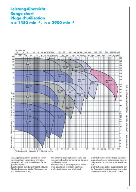
Leistungsübersicht Range chart Plage d’utilisation n = 1450 min -1 , n = 2900 min -1 7 Förderhöhe H / Differential head H / Hauteur manométrique H (m) Förderhöhe H / Differential head H / Hauteur manométrique H (ft) Förderstrom Q / Quantity Q / Débit Q /m3/h Die Zugehörigkeit der einzelnen Typen zum jeweiligen Lagerträger ist im Leistungsfeld mit unterschiedlichen Farben gekennzeichnet. Zugehörigkeit zum Lagerträger bedeutet: Gleiche Lagerung, Welle, Wellenbuchse und Wellenabdichtung. The different bearing bracket sizes are represented on the performance diagram by different colour. For each size of bearing bracket the following parts are identical: bearings, shaft, shaft sleeve and shaft seal. L’attribution des divers types au paliersupport particulier est marquée dans le diagramme de puissance par le coloration. L’attribution au palier-support repré-sente: Exécution identique de paliers, arbre douille d’arbre et étanchéité d’arbre.
- Page 1 and 2: Chemie-Normpumpe aus Technischer Ke
- Page 3 and 4: Die Flanschanschlußmaße entsprech
- Page 5: Wellenabdichtungen Shaft sealing Et
Leistungsübersicht<br />
Range chart<br />
Plage d’utilisation<br />
n = 1450 m<strong>in</strong> -1 , n = 2900 m<strong>in</strong> -1 7<br />
Förderhöhe H / Differential head H / Hauteur manométrique H (m)<br />
Förderhöhe H / Differential head H / Hauteur manométrique H (ft)<br />
Förderstrom Q / Quantity Q / Débit Q /m3/h<br />
Die Zugehörigkeit der e<strong>in</strong>zelnen Typen<br />
zum jeweiligen Lagerträger ist im Leistungsfeld<br />
mit unterschiedlichen Farben<br />
gekennzeichnet.<br />
Zugehörigkeit zum Lagerträger bedeutet:<br />
Gleiche Lagerung, Welle, Wellenbuchse<br />
und Wellenabdichtung.<br />
The different bear<strong>in</strong>g bracket sizes are<br />
represented on the performance diagram<br />
by different colour.<br />
For each size of bear<strong>in</strong>g bracket the follow<strong>in</strong>g<br />
parts are identical: bear<strong>in</strong>gs,<br />
shaft, shaft sleeve and shaft seal.<br />
L’attribution des divers types au paliersupport<br />
particulier est marquée dans le<br />
diagramme de puissance par le coloration.<br />
L’attribution au palier-support repré-sente:<br />
Exécution identique de paliers, arbre<br />
douille d’arbre et étanchéité d’arbre.


