EVO ACE500ET-ACE800E - Tege Torantriebe
EVO ACE500ET-ACE800E - Tege Torantriebe
EVO ACE500ET-ACE800E - Tege Torantriebe

You also want an ePaper? Increase the reach of your titles
YUMPU automatically turns print PDFs into web optimized ePapers that Google loves.
GB D NL<br />
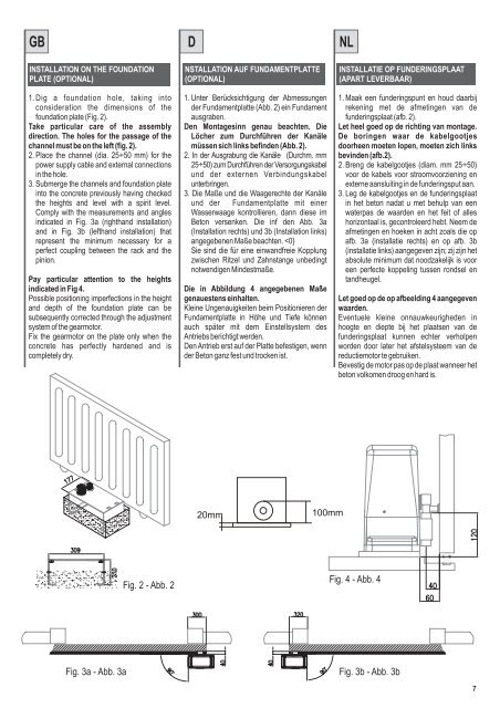
INSTALLATION ON THE FOUNDATION<br />
PLATE (OPTIONAL)<br />
1.Dig a foundation hole, taking into<br />
consideration the dimensions of the<br />
foundation plate (Fig. 2).<br />
Take particular care of the assembly<br />
direction. The holes for the passage of the<br />
channel must be on the left (fig. 2).<br />
2. Place the channel (dia. 25÷50 mm) for the<br />
power supply cable and external connections<br />
in the hole.<br />
3. Submerge the channels and foundation plate<br />
into the concrete previously having checked<br />
the heights and level with a spirit level.<br />
Comply with the measurements and angles<br />
indicated in Fig. 3a (righthand installation)<br />
and in Fig. 3b (lefthand installation) that<br />
represent the minimum necessary for a<br />
perfect coupling between the rack and the<br />
pinion.<br />
Pay particular attention to the heights<br />
indicated in Fig 4.<br />
Possible positioning imperfections in the height<br />
and depth of the foundation plate can be<br />
subsequently corrected through the adjustment<br />
system of the gearmotor.<br />
Fix the gearmotor on the plate only when the<br />
concrete has perfectly hardened and is<br />
completely dry.<br />
Fig. 2 - Abb. 2<br />
NSTALLATION AUF FUNDAMENTPLATTE<br />
(OPTIONAL)<br />
1. Unter Berücksichtigung der Abmessungen<br />
der Fundamentplatte (Abb. 2) ein Fundament<br />
ausgraben.<br />
Den Montagesinn genau beachten. Die<br />
Löcher zum Durchführen der Kanäle<br />
müssen sich links befinden (Abb. 2).<br />
2. In der Ausgrabung die Kanäle (Durchm. mm<br />
25÷50) zum Durchführen der Versorgungskabel<br />
und der externen Verbindungskabel<br />
unterbringen.<br />
3. Die Maße und die Waagerechte der Kanäle<br />
und der Fundamentplatte mit einer<br />
Wasserwaage kontrollieren, dann diese im<br />
Beton versenken. Die inf den Abb. 3a<br />
(Installation rechts) und 3b (Installation links)<br />
angegebenen Maße beachten.