Template BA B168xH238 - Hörmann
Template BA B168xH238 - Hörmann
Template BA B168xH238 - Hörmann

You also want an ePaper? Increase the reach of your titles
YUMPU automatically turns print PDFs into web optimized ePapers that Google loves.
TR10A082-C RE / 02.2011<br />
DE<br />
EN<br />
FR<br />
NL<br />
IT<br />
ES<br />
PT<br />
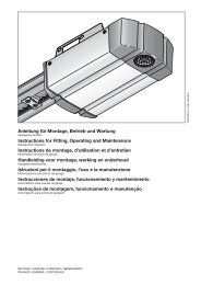
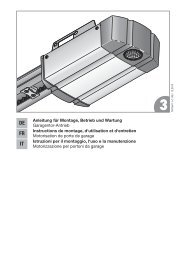
Anleitung für Montage, Betrieb und Wartung<br />
Schiebetorantrieb<br />
Instructions for Fitting, Operating and Maintenance<br />
Sliding Gate Operator<br />
Instructions de montage, d’utilisation et de maintenance<br />
Motorisation de portail coulissant<br />
Montage-, bedienings- en onderhoudshandleiding<br />
Schuifhekaandrijving<br />
Istruzioni per il montaggio, l‘uso e la manutenzione<br />
Motorizzazione per cancelli scorrevoli<br />
Instrucciones de montaje, funcionamiento y mantenimiento<br />
Automatismo para cancela corredera<br />
Instruções de montagem, funcionamento e manutenção<br />
Automatismo para portas de correr
DEUTSCH ........................ 6<br />
ENGLISH ........................ 25<br />
FRANÇAIS ....................... 44<br />
NEDERLANDS. ................... 64<br />
ITALIANO. ....................... 84<br />
ESPAÑOL. ...................... 104<br />
PORTUGUÊS. ................... 124<br />
........................ 144<br />
2 TR10A082-C RE / 02.2011
TR10A082-C RE / 02.2011 3
4 TR10A082-C RE / 02.2011
TR10A082-C RE / 02.2011 5
DEUTSCH<br />
Inhaltsverzeichnis<br />
A Mitgelieferte Artikel................................................. 3<br />
B Benötigtes Werkzeug zur Montage<br />
des Schiebetorantriebes......................................... 4<br />
C 1 Montagezubehör für<br />
die Kunststoff-Zahnstangen................................... 5<br />
C 2 Zahnstange aus Kunststoff mit Stahlkern<br />
(Montagelasche unten)........................................... 5<br />
C 3 Zahnstange aus Kunststoff mit Stahlkern<br />
(Montagelasche oben)............................................ 5<br />
C 4 Zahnstange aus Stahl, verzinkt.............................. 5<br />
C 5 Montagezubehör für die Stahl-Zahnstangen........ 5<br />
Bohrschablone..................................................... 165<br />
1 Zu dieser Anleitung................................................. 7<br />
1.1 Mitgeltende Unterlagen............................................. 7<br />
1.2 Verwendete Warnhinweise........................................ 7<br />
1.3 Verwendete Definitionen............................................ 7<br />
1.4 Verwendete Symbole................................................ 7<br />
1.5 Verwendete Abkürzungen......................................... 8<br />
1.6 Hinweise zum Bildteil................................................ 8<br />
2 Sicherheitshinweise........................................ 8<br />
2.1 Bestimmungsgemäße Verwendung.......................... 8<br />
2.2 Nicht bestimmungsgemäße Verwendung................. 8<br />
2.3 Qualifikation des Monteurs....................................... 8<br />
2.4 Sicherheitshinweise zur Montage, Wartung,<br />
Reparatur und Demontage der Toranlage................. 8<br />
2.5 Sicherheitshinweise zur Montage.............................. 9<br />
2.6 Sicherheitshinweise zur Inbetriebnahme<br />
und zum Betrieb........................................................ 9<br />
2.7 Sicherheitshinweise zum Gebrauch des<br />
Handsenders............................................................. 9<br />
2.8 Geprüfte Sicherheitseinrichtungen............................ 9<br />
3 Montage................................................................... 9<br />
3.1 Tor/Toranlage überprüfen und vorbereiten................ 9<br />
3.2 Montage des Schiebetorantriebs............................ 10<br />
3.3 Zahnstange montieren............................................ 11<br />
3.4 Schiebetorantrieb elektrisch anschließen............... 11<br />
3.5 Platinenhalter montieren.......................................... 11<br />
3.6 Magnethalter montieren.......................................... 11<br />
3.7 Antriebe verriegeln.................................................. 11<br />
3.8 Zusatzkomponenten/Zubehör anschließen............. 11<br />
4 Inbetriebnahme...................................................... 13<br />
4.1 Vorbereitung............................................................ 13<br />
4.2 Torendlagen einlernen............................................. 13<br />
4.3 Kräfte lernen............................................................ 14<br />
4.4 Startpunkte für Schleichfahrt<br />
beim Öffnen und Schließen ändern......................... 15<br />
4.5 Reversiergrenze....................................................... 15<br />
4.6 Automatischer Zulauf.............................................. 15<br />
5 Funktionen der DIL‐Schalter................................ 15<br />
5.1 DIL-Schalter 1......................................................... 15<br />
5.2 DIL-Schalter 2......................................................... 16<br />
5.3 DIL-Schalter 3 / DIL-Schalter 4............................... 16<br />
5.4 DIL-Schalter 5 / DIL-Schalter 6............................... 16<br />
5.5 DIL-Schalter 7......................................................... 16<br />
5.6 DIL-Schalter 8 / DIL-Schalter 9............................... 16<br />
5.7 DIL-Schalter 10....................................................... 16<br />
5.8 DIL-Schalter 11....................................................... 17<br />
5.9 DIL-Schalter 12....................................................... 17<br />
5.10 DIL-Schalter 13....................................................... 17<br />
5.11 DIL-Schalter 14....................................................... 17<br />
5.12 DIL-Schalter 15....................................................... 17<br />
5.13 DIL-Schalter 16....................................................... 17<br />
6 Funk........................................................................ 17<br />
6.1 Handsender HSM 4................................................. 17<br />
6.2 Funk-Empfänger...................................................... 18<br />
6.3 Einlernen von Handsendern<br />
an einem integrierten Empfänger............................ 18<br />
6.4 Betrieb..................................................................... 18<br />
6.5 Löschen aller Funkcodes eines integrierten<br />
Empfängers............................................................. 18<br />
7 Abschließende Arbeiten........................................ 19<br />
7.1 Warnschild befestigen............................................. 19<br />
8 Betrieb.................................................................... 19<br />
8.1 Benutzer einweisen................................................. 19<br />
8.2 Funktionsprüfung.................................................... 19<br />
8.3 Normal-Betrieb........................................................ 19<br />
8.4 Verhalten bei einem Spannungsausfall................... 19<br />
8.5 Verhalten nach einem Spannungsausfall................ 19<br />
9 Prüfung und Wartung............................................ 19<br />
10 Anzeigen von Betriebszuständen,<br />
Fehlern und Warnmeldungen............................... 20<br />
10.1 LED GN................................................................... 20<br />
10.2 LED RT.................................................................... 20<br />
10.3 Anzeige von Fehler-/Warnmeldungen..................... 20<br />
10.4 Fehlerquittierung..................................................... 21<br />
11 Steuerung zurücksetzen /<br />
Werkseinstellungen wiederherstellen................. 21<br />
12 Demontage und Entsorgung................................ 21<br />
13 Optionales Zubehör............................................... 21<br />
14 Garantiebedingungen............................................ 21<br />
15 Auszug aus der Einbauerklärung......................... 22<br />
16 Technische Daten.................................................. 22<br />
17 Übersicht DIL-Schalter Funktionen..................... 23<br />
Bildteil........................................................ 144<br />
Weitergabe sowie Vervielfältigung dieses Dokuments,<br />
Verwertung und Mitteilung seines Inhalts sind verboten,<br />
soweit nicht ausdrücklich gestattet. Zuwiderhandlungen<br />
verpflichten zu Schadenersatz. Alle Rechte für den Fall der<br />
Patent-, Gebrauchsmuster- oder Geschmacksmustereintragung<br />
vorbehalten. Änderungen vorbehalten.<br />
6 TR10A082-C RE / 02.2011
DEUTSCH<br />
Sehr geehrte Kundin, sehr geehrter Kunde,<br />
wir freuen uns, dass Sie sich für ein Qualitätsprodukt aus<br />
unserem Hause entschieden haben.<br />
1 Zu dieser Anleitung<br />
Diese Anleitung ist eine Originalbetriebsanleitung im Sinne<br />
der EG-Richtlinie 2006/42/EG. Lesen Sie die Anleitung<br />
sorgfältig und vollständig durch, sie enthält wichtige<br />
Informationen zum Produkt. Beachten Sie die Hinweise und<br />
befolgen Sie insbesondere die Sicherheits- und<br />
Warnhinweise.<br />
Bewahren Sie diese Anleitung sorgfältig auf!<br />
1.1 Mitgeltende Unterlagen<br />
Für die sichere Nutzung und Wartung der Toranlage müssen<br />
folgende Unterlagen zur Verfügung stehen:<br />
• diese Anleitung<br />
• beigefügtes Prüfbuch<br />
• die Anleitung vom Schiebetor<br />
1.2<br />
Verwendete Warnhinweise<br />
Das allgemeine Warnsymbol kennzeichnet eine<br />
Gefahr, die zu Verletzungen oder zum Tod führen kann. Im<br />
Textteil wird das allgemeine Warnsymbol in Verbindung mit<br />
den nachfolgend beschriebenen Warnstufen verwendet. Im<br />
Bildteil verweist eine zusätzlich Angabe auf die<br />
Erläuterungen im Textteil.<br />
GEFAHR<br />
Kennzeichnet eine Gefahr, die unmittelbar zum Tod oder zu<br />
schweren Verletzungen führt.<br />
WARNUNG<br />
Kennzeichnet eine Gefahr, die zum Tod oder zu schweren<br />
Verletzungen führen kann.<br />
VORSICHT<br />
Kennzeichnet eine Gefahr, die zu leichten oder mittleren<br />
Verletzungen führen kann.<br />
ACHTUNG<br />
Kennzeichnet eine Gefahr, die zur Beschädigung oder<br />
Zerstörung des Produkts führen kann.<br />
1.3 Verwendete Definitionen<br />
Aufhaltezeit<br />
Wartezeit vor der Zufahrt des Tores aus der Endlage Tor-Auf<br />
oder Teilöffnung bei automatischem Zulauf.<br />
Automatischer Zulauf<br />
Selbsttätiges Schließen des Tores nach Ablauf einer Zeit, aus<br />
der Endlage Tor-Auf oder Teilöffnung.<br />
DIL-Schalter<br />
Auf der Steuerungsplatine befindliche Schalter zum Einstellen<br />
der Steuerung.<br />
Durchfahrtslichtschranke<br />
Nach Durchfahren des Tores und der Lichtschranke wird die<br />
Aufhaltezeit verkürzt, so dass sich das Tor kurze Zeit später<br />
schließt.<br />
Impulsfolgesteuerung<br />
Bei jeder Tastenbetätigung wird das Tor entgegen der letzten<br />
Fahrtrichtung gestartet, oder eine Torfahrt wird gestoppt.<br />
Kraftlernfahrt<br />
Bei dieser Lernfahrt werden die Kräfte eingelernt, die für das<br />
Verfahren des Tores notwendig sind.<br />
Normal-Betrieb<br />
Torfahrt mit den eingelernten Strecken und Kräften.<br />
Referenzfahrt<br />
Torfahrt in Richtung Endlage Tor-Zu, um die Grundstellung<br />
festzulegen.<br />
Reversierfahrt/Sicherheitsrücklauf<br />
Verfahren des Tores in Gegenrichtung beim Ansprechen der<br />
Sicherheitseinrichtung oder Kraftbegrenzung.<br />
Reversiergrenze<br />
Bis zur Reversiergrenze, kurz vor der Endlage Tor-Zu, wird<br />
beim Ansprechen einer Sicherheitseinrichtung eine Fahrt in<br />
Gegenrichtung (Reversierfahrt) ausgelöst. Beim Überfahren<br />
dieser Grenze gibt es dieses Verhalten nicht, damit das Tor<br />
ohne Fahrtunterbrechung sicher die Endlage erreicht.<br />
Schleichfahrt<br />
Der Bereich in dem das Tor sehr langsam verfährt, um sanft<br />
gegen die Endlage zu fahren.<br />
Selbsthaltebetrieb/Selbsthaltung<br />
Der Antrieb verfährt nach einem Impuls selbständig bis in die<br />
Endlage.<br />
Teilöffnung<br />
Der Verfahrweg, der für den Personendurchgang geöffnet<br />
wird.<br />
Totmannbetrieb<br />
Torfahrt, die nur so lange durchgeführt wird, wie die<br />
entsprechenden Taster betätigt werden.<br />
Vollöffnung<br />
Der Verfahrweg, wenn das Tor vollständig geöffnet wird.<br />
Vorwarnzeit<br />
Die Zeit zwischen dem Fahrbefehl (Impuls) und dem Beginn<br />
der Torfahrt.<br />
Werksreset<br />
Zurücksetzen der eingelernten Werte in den<br />
Auslieferungszustand / die Werkseinstellung.<br />
1.4<br />
Symbole<br />
Verwendete Symbole<br />
siehe Textteil<br />
Im Beispiel bedeutet 2.2:<br />
siehe Textteil, Kapitel 2.2<br />
wichtiger Hinweis zur Vermeidung von<br />
Sachschäden<br />
TR10A082-C RE / 02.2011 7
DEUTSCH<br />
Leichtgängigkeit beachten<br />
siehe ggf. gesonderte Montageanleitung<br />
für Not-Akku<br />
1.6 Hinweise zum Bildteil<br />
Im Bildteil wird die Antriebsmontage mit einem Antrieb ohne<br />
Bodenplatte an einem Schiebetor dargestellt, an dem sich der<br />
Antrieb innen rechts vom geschlossenen Tor befindet. Bei<br />
Montage- bzw. Programmierabweichungen zum Antrieb mit<br />
Bodenplatte oder Schiebetor, an dem sich der Antrieb innen<br />
links vom geschlossenen Tor befindet, wird dieses zusätzlich<br />
gezeigt.<br />
Alle Maßangaben im Bildteil sind in [mm].<br />
Schiebetorantrieb Standard<br />
Schiebetorantrieb verstärkte Ausführung<br />
Spannungsausfall<br />
Spannungsrückkehr<br />
hörbares Einrasten<br />
Werkseinstellung der DIL-Schalter<br />
1.5 Verwendete Abkürzungen<br />
Farbcode für Leitungen, Einzeladern und Bauteile<br />
Die Abkürzungen der Farben für Leitung- und<br />
Aderkennzeichnung sowie Bauteilen folgen dem<br />
internationalen Farbcode nach IEC 757:<br />
BN<br />
GN<br />
WH<br />
YE<br />
Braun<br />
Grün<br />
Weiß<br />
Gelb<br />
2 Sicherheitshinweise<br />
ACHTUNG:<br />
WICHTIGE SICHERHEITSANWEISUNGEN.<br />
FÜR DIE SICHERHEIT VON PERSONEN IST ES WICHTIG,<br />
DIESEN ANWEISUNGEN FOLGE ZU LEISTEN. DIESE<br />
ANWEISUNGEN SIND AUFZUBEWAHREN.<br />
2.1 Bestimmungsgemäße Verwendung<br />
Der Schiebetorantrieb ist ausschließlich für den Betrieb von<br />
leichtgängigen Schiebetoren, abhängig vom Antriebstyp, im<br />
privaten Bereich vorgesehen. Die max. zulässige Torgröße<br />
und das max. Gewicht dürfen nicht überschritten werden.<br />
Beachten Sie die Herstellerangaben bezüglich der<br />
Kombination von Tor und Antrieb. Mögliche Gefährdungen im<br />
Sinne der DIN EN 13241-1 werden durch die Konstruktion<br />
und Montage nach unseren Vorgaben vermieden. Toranlagen,<br />
die sich im öffentlich zugänglichen Bereich befinden und über<br />
nur eine Schutzeinrichtung, z.B. Kraftbegrenzung verfügen,<br />
dürfen nur unter Aufsicht betrieben werden.<br />
2.2 Nicht bestimmungsgemäße Verwendung<br />
Ein Dauerbetrieb und der Einsatz im gewerblichen Bereich ist<br />
abhängig vom Antriebstyp nicht zulässig.<br />
Ein Einsatz an Toren mit Steigung oder Gefälle ist nicht<br />
zulässig.<br />
2.3 Qualifikation des Monteurs<br />
Nur die korrekte Montage und Wartung durch einen<br />
kompetenten/sachkundigen Betrieb oder eine kompetente/<br />
sachkundige Person in Übereinstimmung mit den Anleitungen<br />
kann die sichere und vorgesehene Funktionsweise einer<br />
Montage sicherstellen. Eine sachkundige Person ist gemäß<br />
EN 12635 eine Person, die über eine geeignete Ausbildung,<br />
qualifiziertes Wissen und praktische Erfahrung verfügt, um<br />
eine Toranlage richtig und sicher zu montieren, zu prüfen und<br />
zu warten.<br />
2.4<br />
Sicherheitshinweise zur Montage, Wartung,<br />
Reparatur und Demontage der Toranlage<br />
WARNUNG<br />
Verletzungsgefahr bei Fehler in der Toranlage<br />
▶ Siehe Warnhinweis Kapitel 3.1<br />
WARNUNG<br />
Verletzungsgefahr durch unerwartete Torfahrt<br />
▶ Siehe Warnhinweis Kapitel 9<br />
Die Montage, Wartung, Reparatur und Demontage der<br />
Toranlage und des Schiebetorantriebs muss durch<br />
Sachkundige ausgeführt werden.<br />
8 TR10A082-C RE / 02.2011
DEUTSCH<br />
▶<br />
Bei Versagen der Toranlage oder des Schiebetorantriebs<br />
(Schwergängigkeit oder andere Störungen) unmittelbar<br />
einen Sachkundigen mit der Prüfung / Reparatur<br />
beauftragen.<br />
2.5 Sicherheitshinweise zur Montage<br />
Der Sachkundige muss darauf achten, dass bei der<br />
Durchführung der Montagearbeiten die geltenden Vorschriften<br />
zur Arbeitssicherheit sowie die Vorschriften für den Betrieb<br />
von elektrischen Geräten befolgt werden. Hierbei sind die<br />
nationalen Richtlinien zu beachten. Mögliche Gefährdungen<br />
im Sinne der DIN EN 13241-1 werden durch die Konstruktion<br />
und Montage nach unseren Vorgaben vermieden.<br />
Nach Abschluss der Montage muss der Aufsteller der<br />
Toranlage entsprechend des Geltungsbereiches die<br />
Konformität nach DIN EN 13241-1 erklären.<br />
Netzspannung<br />
▶ Siehe Warnhinweis Kapitel 3.4<br />
gefahr<br />
WARNUNG<br />
Verletzungsgefahr durch ungewollte Torbewegung<br />
▶ Siehe Warnhinweis Kapitel 3.2<br />
▶ Siehe Warnhinweis Kapitel 3.8<br />
WARNUNG<br />
Nicht geeignete Befestigungsmaterialien<br />
▶ Siehe Warnhinweis Kapitel 3.2.3<br />
2.6<br />
Sicherheitshinweise zur Inbetriebnahme und<br />
zum Betrieb<br />
WARNUNG<br />
Verletzungsgefahr bei Torbewegung<br />
▶ Siehe Warnhinweis Kapitel 4 und 8<br />
Quetsch- und Schergefahr<br />
▶ Siehe Warnhinweis Kapitel 4 und 8<br />
VORSICHT<br />
Verletzungsgefahr bei zu hoch eingestelltem Kraftwert<br />
▶ Siehe Warnhinweis Kapitel 4.3.1<br />
2.7<br />
Sicherheitshinweise zum Gebrauch des<br />
Handsenders<br />
Warnung<br />
Verletzungsgefahr bei ungewollter Torbewegung<br />
▶ Siehe Warnhinweis Kapitel 6.1<br />
Vorsicht<br />
Verletzungsgefahr durch unbeabsichtigte Torfahrt<br />
▶ Siehe Warnhinweis Kapitel 6<br />
2.8 Geprüfte Sicherheitseinrichtungen<br />
Sicherheitsrelevante Funktionen bzw. Komponenten der<br />
Steuerung, wie die Kraftbegrenzung, externe Lichtschranken<br />
und Schließkantensicherung, sofern vorhanden, wurden<br />
entsprechend Kategorie 2, PL „c“ der EN ISO 13849-1:2008<br />
konstruiert und geprüft.<br />
WARNUNG<br />
Verletzungsgefahr durch nicht funktionierende<br />
Sicherheitseinrichtungen<br />
▶ Siehe Warnhinweis Kapitel 4.6<br />
2.8.1 Sicherheitshinweise zur Einhaltung der<br />
Betriebskräfte<br />
Wenn Sie diese Anleitung und zusätzlich die folgenden<br />
Bedingungen beachten, kann davon ausgegangen werden,<br />
dass die Betriebskräfte nach DIN EN 12453 eingehalten<br />
werden:<br />
• Der Schwerpunkt des Tores muss in der Mitte des Tores<br />
liegen (maximal zulässige Abweichung ± 20%).<br />
• Der Torlauf ist leichtgängig und weist keinerlei Steigung/<br />
Gefälle (0%) auf.<br />
• An der oder den Schließkanten ist das Hörmann<br />
Dämpfungsprofil DP3 montiert. Dieses muss separat<br />
bestellt werden (Artikel-Nr.: 436 388).<br />
• Der Antrieb ist auf langsame Geschwindigkeit<br />
programmiert (siehe Kapitel 4.3.2).<br />
• Die Reversiergrenze bei 50 mm Öffnungsweite wird auf<br />
der ganzen Länge der Hauptschließkante überprüft und<br />
eingehalten.<br />
• Der Tragrollenabstand bei freitragenden Toren (maximale<br />
Breite 6200 mm, maximale Öffnungsweite 4000 mm)<br />
beträgt maximal 2000 mm.<br />
3 Montage<br />
ACHTUNG:<br />
WICHTIGE ANWEISUNGEN FÜR SICHERE MONTAGE.<br />
ALLE ANWEISUNGEN BEACHTEN, FALSCHE MONTAGE<br />
KANN ZU ERNSTHAFTEN VERLETZUNGEN FÜHREN.<br />
3.1<br />
Tor/Toranlage überprüfen und vorbereiten<br />
WARNUNG<br />
Verletzungsgefahr bei Fehler in der Toranlage<br />
Ein Fehler in der Toranlage oder ein falsch ausgerichtetes<br />
Tor können zu schweren Verletzungen führen<br />
▶ Benutzen Sie die Toranlage nicht, wenn Reparaturoder<br />
Einstellarbeiten durchgeführt werden müssen.<br />
▶ Kontrollieren Sie die gesamte Toranlage (Gelenke,<br />
Lager des Tores und Befestigungsteile) auf Verschleiß<br />
und eventuelle Beschädigungen.<br />
▶ Prüfen Sie, ob Rost, Korrosion oder Risse vorhanden<br />
sind.<br />
TR10A082-C RE / 02.2011 9
DEUTSCH<br />
Die Konstruktion des Schiebetorantriebs ist nicht für den<br />
Betrieb schwergängiger Tore ausgelegt, das heißt Tore, die<br />
nicht mehr oder nur schwer von Hand geöffnet oder<br />
geschlossen werden können.<br />
Der Antrieb ist nur für Tore ausgelegt, die keinerlei Steigung<br />
oder Gefälle aufweisen.<br />
Das Tor muss sich mechanisch in einem fehlerfreien Zustand<br />
befinden, so dass es auch von Hand leicht zu bedienen ist<br />
(EN 12604).<br />
▶ Prüfen Sie, ob sich das Tor richtig öffnen und schließen<br />
lässt.<br />
▶ Setzen Sie die mechanischen Verriegelungen des Tores,<br />
die nicht für eine Betätigung mit einem Schiebetorantrieb<br />
benötigt werden, außer Betrieb. Hierzu zählen<br />
insbesondere die Verriegelungsmechanismen des<br />
Torschlosses<br />
▶ Sichern Sie das Tor mechanisch gegen das Herauslaufen<br />
aus seinen Führungen.<br />
▶ Wechseln Sie für die Montage und Inbetriebnahme<br />
zum Bildteil. Beachten Sie den entsprechenden<br />
Textteil, wenn Sie durch das Symbol für den<br />
Textverweis darauf hingewiesen werden.<br />
3.2<br />
Montage des Schiebetorantriebs<br />
WARNUNG<br />
Verletzungsgefahr durch ungewollte Torbewegung<br />
Bei einer falschen Montage oder Handhabung des Antriebs<br />
können ungewollte Torbewegungen ausgelöst und dabei<br />
Personen oder Gegenstände eingeklemmt werden.<br />
▶ Befolgen Sie alle Anweisungen, die in dieser Anleitung<br />
enthalten sind.<br />
3.2.1<br />
Fundament<br />
ACHTUNG<br />
Störungen in den Steuerleitungen<br />
Zusammen verlegte Steuerleitungen und<br />
Versorgungsleitungen, können zu Funktionsstörungen<br />
führen.<br />
▶ Verlegen Sie die Steuerleitungen des Antriebs<br />
(24 V DC) in einem getrennten Installationssystem zu<br />
den Versorgungsleitungen (230/240 V AC).<br />
1. Es ist erforderlich, dass ein Fundament gegossen wird<br />
(siehe Bild 1a/1b). Die Markierung * steht für die<br />
frostfreie Tiefe (in Deutschland = 80 cm).<br />
Bei Verwendung einer Schließkantensicherung muss ein<br />
größeres Fundament gegossen werden (siehe<br />
Bild 1c/1d).<br />
2. Bei dem Antriebstyp mit Bodenplatte ist die Verwendung<br />
von Beton ≥ B25/C25 (verdichtet) erforderlich.<br />
3. Bei Toren mit innenliegenden Laufrollen ist ggf. ein<br />
Sockelfundament erforderlich.<br />
4. Die Netzzuleitung mit 230/240 V ~ muss durch ein<br />
Leerrohr im Fundament erfolgen. Die Zuleitung für den<br />
Anschluss von Zubehör mit 24 V muss durch ein<br />
separates Leerrohr, getrennt von der Netzzuleitung,<br />
erfolgen (siehe Bild 1.1).<br />
Hinweis:<br />
Das Fundament muss vor den folgenden Montageschritten<br />
ausreichend ausgehärtet sein.<br />
3.2.2 Anbaumaße ermitteln<br />
1. Legen Sie die Bohrposition der vier Bohrungen auf der<br />
Oberfläche des Fundaments fest.<br />
Verwenden Sie je nach Antriebstyp:<br />
– Die Bohrschablone am Ende dieser Anleitung für<br />
Ø 12 mm Bohrungen bei Verwendung der<br />
Stockschrauben (siehe Bild 2a).<br />
– Die Bodenplatte für Ø 10 mm Bohrungen bei<br />
Verwendung der Schwerlastanker (siehe Bild 2b).<br />
2. Wählen Sie die verwendete Zahnstange aus unten<br />
stehender Tabelle aus und entnehmen die minimalen und<br />
maximalen Anbaumaße (Maß A).<br />
3.2.3<br />
▶<br />
Zahnstange<br />
min.<br />
Maß A (mm)<br />
max.<br />
436 444 124 136<br />
438 759 126 138<br />
438 631 125 129<br />
438 632 129 133<br />
Verankerung<br />
Siehe Bild 2a.1/2b.1<br />
WARNUNG<br />
Nicht geeignete Befestigungsmaterialien<br />
Die Verwendung nicht geeigneter Befestigungsmaterialien<br />
kann dazu führen, dass der Antrieb nicht sicher befestigt ist<br />
und sich lösen kann.<br />
▶ Verwenden Sie das mitgelieferte Befestigungsmaterial<br />
nur für Beton ≥ B25/C25 (siehe Bilder 1.1/2.1).<br />
ACHTUNG<br />
Beschädigung durch Schmutz<br />
Bohrstaub und Späne können zu Funktionsstörungen<br />
führen.<br />
▶ Decken Sie bei Bohrarbeiten den Antrieb ab.<br />
▶<br />
▶<br />
Überprüfen Sie nach dem Bohren die Tiefe der Bohrung.<br />
Bohrung<br />
Ø 12 mm für Stockschrauben<br />
Ø 10 mm für Schwerlastanker<br />
Tiefe<br />
80 mm<br />
105 mm<br />
Verwenden Sie zur Montage der Stockschrauben den<br />
Steckschlüssel aus dem Lieferumfang.<br />
3.2.4 Antriebsgehäuse montieren<br />
▶ Siehe Bild 3 – 3.5<br />
Achtung!<br />
Beschädigung durch Feuchtigkeit<br />
▶ Schützen Sie beim Öffnen des Antriebsgehäuses die<br />
Steuerung vor Feuchtigkeit<br />
▶ Öffnen Sie das Antriebsgehäuse, entriegeln den Antrieb<br />
und entfernen den Platinenhalter.<br />
Beim Entriegeln senken sich der Motor und das Zahnrad<br />
in das Gehäuse ab.<br />
▶ Schneiden Sie ggf. die Leerrohr-Dichtungen<br />
entsprechend der Leerrohre passend zu.<br />
▶ Ziehen Sie beim Aufsetzen des Gehäuses auf die Stockschrauben<br />
oder auf die Bodenplatte, die Netz zuleitung<br />
und ggf. die 24 V-Anschlussleitung von unten, verzugsfrei<br />
durch die Leerrohr-Dichtungen in das Gehäuse ein.<br />
10 TR10A082-C RE / 02.2011
DEUTSCH<br />
▶<br />
3.3<br />
Achten Sie beim Festschrauben auf eine waagerechte,<br />
stabile und sichere Befestigung.<br />
Zahnstange montieren<br />
Vor der Montage:<br />
▶ Überprüfen Sie, ob die erforderliche Einschraubtiefe zur<br />
Verfügung steht.<br />
▶ Verwenden Sie zur Montage der Zahnstangen die<br />
Verbindungselemente (Schrauben und Muttern, etc.) aus<br />
dem Montagezubehör (siehe Bild C1 bzw. Bild C5).<br />
Diese müssen separat bestellt werden.<br />
Hinweis:<br />
• Abweichend vom Bildteil müssen bei anderen Torarten –<br />
auch hinsichtlich der Einschraublänge – die jeweils<br />
geeigneten Verbindungselemente benutzt werden (z.B.<br />
müssen bei Holztoren entsprechende Holzschrauben<br />
verwendet werden).<br />
• Abweichend vom Bildteil kann sich je nach Materialstärke<br />
oder Werkstofffestigkeit der notwendige<br />
Kernlochdurchmesser ändern. Der notwendige<br />
Durchmesser kann bei Alu Ø 5,0–5,5 mm und bei Stahl<br />
Ø 5,7–5,8 mm betragen.<br />
Montage:<br />
▶ Siehe Bild 4 – 4.3<br />
Der Schiebetorantrieb muss entriegelt sein (siehe Bild 3.2).<br />
▶ Achten Sie bei der Montage auf versatzfreie Übergänge<br />
zwischen den einzelnen Zahnstangen, damit ein<br />
gleichmäßiger Lauf des Tores gewährleistet wird.<br />
▶ Sie müssen nach der Montage die Zahnstangen und das<br />
Zahnrad des Antriebs zueinander ausrichten. Dazu<br />
können sowohl die Zahnstangen als auch das<br />
Antriebsgehäuse justiert werden.<br />
Falsch montierte oder schlecht ausgerichtete<br />
Zahnstangen können zu unbeabsichtigtem<br />
Reversieren führen. Die vorgegebenen Maße müssen<br />
zwingend eingehalten werden!<br />
▶ Versiegeln Sie das Gehäuse gegen Feuchtigkeit und<br />
Ungeziefer (siehe Bild 4.4).<br />
3.4 Schiebetorantrieb elektrisch anschließen<br />
▶ Siehe Bild 4.5<br />
Netzspannung<br />
gefahr<br />
Bei Kontakt mit der Netzspannung besteht die Gefahr eines<br />
tödlichen Stromschlags.<br />
Beachten Sie daher unbedingt folgende Hinweise:<br />
▶ Elektroanschlüsse dürfen nur von einer Elektrofachkraft<br />
durchgeführt werden.<br />
▶ Die bauseitige Elektroinstallation muss den jeweiligen<br />
Schutzbestimmungen entsprechen (230/240 V AC,<br />
50/60 Hz).<br />
▶ Ziehen Sie vor allen Arbeiten am Antrieb den<br />
Netzstecker.<br />
▶<br />
Schließen Sie die Netzspannung direkt an der<br />
Steckklemme am Transformator mittels Erdkabel NYY an.<br />
3.5 Platinenhalter montieren<br />
▶ Siehe Bild 4.6<br />
1. Befestigen Sie den Platinenhalter mit den zwei zuvor<br />
gelösten Schrauben D , sowie zwei weiteren aus dem<br />
Lieferumfang.<br />
2. Stecken Sie die Anschlussklemmen wieder auf.<br />
3.6 Magnethalter montieren<br />
▶ Siehe Bild 4.7<br />
1. Schieben sie das Tor per Hand in die Tor-Zu Position.<br />
2. Montieren Sie den Magnetschlitten in mittlerer Position<br />
komplett vor.<br />
3. Montieren sie die Zahnstangenklammer so, dass der<br />
Magnet um ca. 20 mm versetzt zu dem Reed-Kontakt im<br />
Platinenhalter positioniert ist.<br />
3.7 Antriebe verriegeln<br />
▶ Siehe Bild 5<br />
Durch das Verriegeln wird der Antrieb wieder eingekuppelt.<br />
▶ Drehen Sie den Mechanismus wieder in die<br />
Verriegelungsposition, der Motor muss dabei leicht<br />
angehoben werden.<br />
3.8 Zusatzkomponenten/Zubehör anschließen<br />
▶ Siehe Übersicht der Steuerungsplatine in Bild 6<br />
warnung<br />
Verletzungsgefahr durch ungewollte<br />
Torbewegung<br />
Bei falsch angebrachten<br />
Steuerungsgeräten (wie z. B. Taster)<br />
können ungewollt Torbewegungen<br />
ausgelöst und dabei Personen oder<br />
Gegenstände eingeklemmt werden.<br />
▶ Bringen Sie Steuergeräte in einer<br />
Höhe von mindestens 1,5 m an<br />
(außer Reichweite von Kindern).<br />
▶ Montieren Sie festinstallierte<br />
Steuerungsgeräte (wie z. B. Taster)<br />
in Sichtweite des Tores, aber<br />
entfernt von sich bewegenden<br />
Teilen.<br />
Bei Versagen vorhandener<br />
Sicherheitseinrichtungen können<br />
Personen oder Gegenstände<br />
eingeklemmt werden.<br />
▶ Bringen Sie entsprechend BGR 232<br />
in der Nähe des Tores mindestes<br />
eine gut erkennbare und leicht<br />
zugängliche Not-Befehlseinrichtung<br />
(Not-Aus) an, mit der im Gefahrfall<br />
die Torbewegung zum Stillstand<br />
gebracht werden kann (siehe<br />
Kapitel 3.8.3)<br />
ACHTUNG<br />
Zerstörung der Elektronik durch Fremdspannung<br />
Fremdspannung an den Anschlussklemmen der Steuerung<br />
führt zu einer Zerstörung der Elektronik.<br />
▶ Legen Sie an den Anschlussklemmen der Steuerung<br />
keine Netzspannung (230/240 V AC) an.<br />
TR10A082-C RE / 02.2011 11
DEUTSCH<br />
Bei Anschluss von Zubehör an folgende Klemmen darf der<br />
entnommene Summenstrom max. 500 mA betragen:<br />
• 24 V=<br />
• SE3/LS<br />
• ext. Funk<br />
• SE1/SE2<br />
3.8.1 Externen Funk-Empfänger* anschließen<br />
▶ Siehe Bild 6.1<br />
▶ Schließen Sie die Adern eines externen Funk-Empfängers<br />
wie folgt an:<br />
– GN an die Klemme 20 (0 V)<br />
– WH an die Klemme 21 (Signal Kanal 1)<br />
– BN an die Klemme 5 (+24 V)<br />
– YE an die Klemme 23 (Signal für die Teilöffnung<br />
Kanal 2). Nur bei einem 2-Kanal-Empfänger.<br />
Hinweis:<br />
Die Antennenlitze vom externen Funk-Empfänger sollte nicht<br />
mit Gegenständen aus Metall (Nägel, Streben, usw.) in<br />
Verbindung kommen. Die beste Ausrichtung muss durch<br />
Versuche ermittelt werden.<br />
3.8.2 Externen Taster* anschließen<br />
▶ Siehe Bild 6.2<br />
Ein oder mehrere Taster mit Schließerkontakten (potentialfrei),<br />
z.B. Schlüsseltaster, können parallel angeschlossen werden,<br />
max. Leitungslänge 10 m.<br />
Impulssteuerung:<br />
▶ Erster Kontakt an Klemme 21<br />
▶ Zweiter Kontakt an Klemme 20<br />
Teilöffnung:<br />
▶ Erster Kontakt an Klemme 23<br />
▶ Zweiter Kontakt an Klemme 20<br />
Hinweis:<br />
Wird für einen externen Taster eine Hilfsspannung benötigt,<br />
steht dafür an Klemme 5 eine Spannung von +24 V DC (gegen<br />
Klemme 20 = 0 V) bereit.<br />
3.8.3 Ausschalter zum Anhalten des Antriebs (Haltbzw.<br />
Not-Aus-Kreis) anschließen<br />
Ein Ausschalter mit Öffnerkontakten (nach 0 V schaltend oder<br />
potentialfrei) wird wie folgt angeschlossen (siehe Bild 6.3):<br />
1. Entfernen Sie die werkseitig eingesetzte Drahtbrücke<br />
zwischen Klemme 12 und Klemme 13.<br />
– Klemme 12: Halt- bzw. Not-Aus-Eingang<br />
– Klemme 13: 0 V<br />
2. Schließen Sie den Schaltausgang oder ersten Kontakt an<br />
Klemme 12 (Halt- bzw. Not-Aus-Eingang) an.<br />
3. Schließen Sie 0 V (Masse) oder den zweiten Kontakt an<br />
Klemme 13 (0 V) an.<br />
Hinweis:<br />
Durch das Öffnen des Kontaktes werden eventuelle Torfahrten<br />
sofort angehalten und dauerhaft unterbunden.<br />
3.8.4 Warnleuchte* anschließen<br />
▶ Siehe Bild 6.4<br />
An den potentialfreien Kontakten am Stecker Option kann<br />
eine Warnleuchte oder die Endlagenmeldung Tor-Zu<br />
angeschlossen werden.<br />
Für den Betrieb (z.B. Warnmeldungen vor und während der<br />
Torfahrt) mit einer 24 V Lampe (max. 7 W) kann die Spannung<br />
am Stecker 24 V = herangezogen werden.<br />
Hinweis:<br />
Eine 230 V-Warnleuchte muss direkt versorgt werden.<br />
3.8.5 Sicherheits-/Schutzeinrichtungen anschließen<br />
▶ Siehe Bild 6.5 – 6.7<br />
Es können Sicherheitseinrichtungen wie Lichtschranken/<br />
Schließkantensicherungen (SKS) oder<br />
8k2-Widerstandskontaktleisten angeschlossen werden:<br />
SE1<br />
SE2<br />
SE3<br />
in Richtung Öffnen, Sicherheitseinrichtung getestet<br />
oder Widerstandskontaktleiste 8k2<br />
in Richtung Schließen, Sicherheitseinrichtung<br />
getestet oder Widerstandskontaktleiste 8k2<br />
in Richtung Schließen, Lichtschranke ohne Testung<br />
oder dynamische 2-Draht-Lichtschranke, z.B. als<br />
Durchfahrtslichtschranke<br />
Die Auswahl der Funktionen für die 3 Sicherheitskreise wird<br />
über DIL-Schalter eingestellt (siehe Kapitel 5).<br />
Klemmenbelegung:<br />
Klemme 20<br />
Klemme 18<br />
Klemmen 71/72/73<br />
Klemme 5<br />
0 V (Spannungsversorgung)<br />
Testsignal<br />
Signal der Sicherheitseinrichtung<br />
+24 V (Spannungsversorgung)<br />
Hinweis:<br />
Sicherheitseinrichtungen ohne Testung (z.B. statische<br />
Lichtschranken) müssen halbjährlich geprüft werden. Sie sind<br />
nur für den Sachschutz zulässig!<br />
3.8.6 Universaladapterplatine UAP1* anschließen<br />
▶ Siehe Bild 6.8<br />
Anschlussmöglichkeit der Universaladapterplatine UAP1.<br />
3.8.7 Not-Akku HNA-Outdoor* anschließen<br />
▶ Siehe Bild 6<br />
Um bei einem Netzausfall das Tor verfahren zu können, ist ein<br />
optionaler Not-Akku anschließbar. Die Umschaltung auf Akku-<br />
Betrieb bei Netzausfall erfolgt automatisch.<br />
WARNUNG<br />
Verletzungsgefahr durch unerwartete Torfahrt<br />
Zu einer unerwarteten Torfahrt kann es kommen, wenn trotz<br />
gezogenem Netzstecker noch der Not-Akku angeschlossen<br />
ist.<br />
▶ Ziehen Sie bei allen Arbeiten an der Toranlage den<br />
Netzstecker und den Stecker des Not-Akkus.<br />
* Zubehör, ist nicht in der Standard-Ausstattung enthalten!<br />
12 TR10A082-C RE / 02.2011
DEUTSCH<br />
4<br />
Inbetriebnahme<br />
warnung<br />
Verletzungsgefahr bei Torbewegung<br />
Im Bereich des Tores kann es bei<br />
fahrendem Tor zu Verletzungen oder<br />
Beschädigungen kommen.<br />
▶ Stellen Sie sicher, dass keine Kinder<br />
an der Toranlage spielen.<br />
▶ Stellen Sie sicher, dass sich im<br />
Bewegungsbereich des Tores keine<br />
Personen oder Gegenstände<br />
befinden.<br />
▶ Verfügt die Toranlage nur über eine<br />
Sicherheitseinrichtung, dann<br />
betreiben Sie den Schiebetorantrieb<br />
nur, wenn Sie den<br />
Bewegungsbereich des Tores<br />
einsehen können.<br />
▶ Überwachen Sie den Torlauf, bis<br />
das Tor die Endlage erreicht hat.<br />
▶ Durchfahren bzw. durchgehen Sie<br />
Toröffnungen von ferngesteuerten<br />
Toranlagen erst, wenn das Tor zum<br />
Stillstand gekommen ist!<br />
WARNUNG<br />
Quetsch- und Schergefahr<br />
Bei der Torfahrt können Finger oder Gliedmaßen von der<br />
Zahnstange sowie zwischen Tor und Schließkante<br />
eingequetscht oder abgetrennt werden.<br />
▶ Greifen Sie während einer Torfahrt nicht mit den<br />
Fingern an die Zahnstange, das Zahnrad und die<br />
Haupt- und Nebenschließkanten.<br />
4.1 Vorbereitung<br />
▶ Überprüfen Sie vor der ersten Inbetriebnahme alle<br />
Anschlussleitungen auf die korrekte Installation an den<br />
Anschlussklemmen.<br />
▶ Stellen Sie sicher, dass alle DIL-Schalter in der<br />
Werkseinstellung (OFF) stehen (siehe Bild 7), das Tor halb<br />
geöffnet und der Antrieb eingekuppelt ist.<br />
Stellen Sie folgende DIL-Schalter um:<br />
▶ DIL-Schalter 1: Einbaurichtung (siehe Bild 7.1)<br />
– Auf ON, wenn das Tor nach rechts schließt.<br />
– Auf OFF, wenn das Tor nach links schließt.<br />
▶ DIL-Schalter 3-7: Sicherheitseinrichtungen (siehe<br />
Bild 9.6/9.7/9.8)<br />
– Entsprechend der angeschlossenen Sicherheits- und<br />
Schutzeinrichtungen einstellen (siehe Kapitel 5.3 –<br />
5.5). Sind während des Einrichtbetriebes allerdings<br />
nicht aktiv.<br />
4.2 Torendlagen einlernen<br />
4.2.1 Endlagenerfassung Tor-Zu<br />
▶ Siehe Bild 8.1a<br />
Vor dem Einlernen der Endlagen muss der Endschalter (Reed-<br />
Kontakt) angeschlossen sein. Die Adern des Endschalters<br />
müssen an der Klemme REED angeklemmt sein.<br />
Das Optionsrelais hat beim Einrichten die gleiche Funktion<br />
wie die rote LED. Mit einer hier angeschlossenen Lampe lässt<br />
sich die Endschalterstellung aus der Ferne beobachten (siehe<br />
Bild 6.4).<br />
Einlernen der Endlage Tor-Zu:<br />
1. Öffnen Sie das Tor halb.<br />
2. Stellen sie DIL-Schalter 2 (Einrichtbetrieb) auf ON.<br />
Die grüne LED blinkt langsam, die rote LED leuchtet<br />
konstant.<br />
3. Drücken Sie den Platinentaster T und halten ihn<br />
gedrückt.<br />
Das Tor fährt in Schleichfahrt in Richtung Tor-Zu. Bei<br />
Erreichen des Endschalters stoppt das Tor.<br />
4. Lassen Sie den Platinentaster T unverzüglich los.<br />
Die rote LED erlischt.<br />
Das Tor befindet sich nun in der Endlage Tor-Zu.<br />
Hinweis:<br />
Fährt das Tor in Richtung Auf, befindet sich der<br />
DIL‐Schalter 1 in der falschen Position und muss umgestellt<br />
werden. Anschließend die Schritte 1 bis 4 wiederholen.<br />
Falls diese Position des geschlossenen Tores nicht der<br />
gewünschten Endlage Tor-Zu entspricht, muss nachjustiert<br />
werden.<br />
Endlage Tor-Zu nachjustieren:<br />
1. Verändern Sie die Position des Magneten durch<br />
Verschieben des Magnetschlittens.<br />
2. Drücken Sie den Platinentaster T, um der so verstellten<br />
Endlage zu folgen, bis die rote LED wieder erlischt.<br />
3. Wiederholen Sie die Schritte 1. + 2. so lange, bis die<br />
gewünschte Endlage erreicht ist.<br />
4.2.2 Endlagenerfassung Tor-Auf<br />
▶ Siehe Bild 8.1b<br />
Einlernen der Endlage Tor-Auf:<br />
4. Drücken Sie den Platinentaster T und halten ihn<br />
gedrückt.<br />
Das Tor fährt in Schleichfahrt in Richtung Tor-Auf.<br />
5. Lassen Sie den Platinentaster T los, wenn die<br />
gewünschte Endlage Tor-Auf erreicht.<br />
6. Drücken Sie den Platinentaster P, um diese Position zu<br />
bestätigen.<br />
Die grüne LED signalisiert durch ein 2 Sekunden langes,<br />
sehr schnelles Blinken das Erfassen der Endlage Tor-Auf<br />
und erlischt.<br />
4.2.3 Endlagenerfassung Teilöffnung<br />
▶ Siehe Bild 8.1c<br />
Hinweis:<br />
Ist ein Totmannbetrieb eingestellt, ist die Endlagenerfassung<br />
Teilöffnung nicht möglich.<br />
Einlernen der Endlage Teilöffnung:<br />
1. Drücken Sie den Platinentaster T und halten ihn<br />
gedrückt, um das Tor in Richtung Tor-Zu zu fahren.<br />
Die grüne LED blinkt langsam.<br />
2. Lassen Sie den Platinentaster T los, wenn die<br />
gewünschte Endlage Teilöffnung erreicht ist.<br />
3. Drücken Sie den Platinentaster P, um diese Position zu<br />
bestätigen.<br />
Die grüne LED signalisiert durch ein 2 Sekunden langes,<br />
sehr schnelles Blinken das Erfassen der Endlage<br />
Teilöffnung und erlischt.<br />
TR10A082-C RE / 02.2011 13
DEUTSCH<br />
4.2.4<br />
Einrichtbetrieb abschließen<br />
▶ Stellen Sie nach Abschluss des Einlernvorgangs<br />
DIL‐Schalter 2 wieder auf OFF.<br />
Die grüne LED signalisiert durch schnelles Blinken, dass<br />
Kraftlernfahrten durchgeführt werden müssen.<br />
Die Sicherheitseinrichtungen sind wieder aktiv.<br />
4.2.5 Referenzfahrt<br />
▶ Siehe Bild 8.2<br />
Nach dem Einlernen der Endlagen ist die erste Fahrt immer<br />
eine Referenzfahrt. Während der Referenzfahrt wird das<br />
Optionsrelais getaktet und eine angeschlossene Warnleuchte<br />
blinkt.<br />
Referenzfahrt bis Endlage Tor-Zu:<br />
▶ Drücken Sie den Platinentaster T einmal.<br />
Der Antrieb fährt selbständig bis in die Endlage Tor-Zu.<br />
▶ Ist ein Totmannbetrieb eingestellt ( DIL-Schalter 16 auf<br />
ON), drücken Sie den Platinentaster T und halten ihn bis<br />
in die Endlage Tor-Zu gedrückt.<br />
Hinweis:<br />
Ist ein Totmannbetrieb eingestellt (DIL-Schalter 16 auf ON) ist<br />
die Inbetriebnahme hier beendet.<br />
4.3 Kräfte lernen<br />
Nach dem Einlernen der Endlagen und der Referenzfahrt<br />
müssen Kraftlernfahrten durchgeführt werden. Hierfür sind<br />
drei ununterbrochene Tor-Zyklen erforderlich, bei denen keine<br />
Sicherheitseinrichtung ansprechen darf. Die Erfassung der<br />
Kräfte erfolgt in beide Richtungen automatisch im<br />
Selbsthaltebetrieb und das Optionsrelais wird getaktet.<br />
Während des gesamten Lernvorgangs blinkt die grüne LED.<br />
Nach Abschluss der Kraftlernfahrten leuchtet diese dann<br />
konstant (siehe Bild 9.1).<br />
▶ Die beiden folgenden Vorgänge müssen dreimal<br />
durchgeführt werden.<br />
Kraftlernfahrten:<br />
▶ Drücken Sie den Platinentaster T einmal.<br />
Der Antrieb fährt selbständig bis in die Endlage Tor-Auf.<br />
▶ Drücken Sie den Platinentaster T einmal.<br />
Der Antrieb fährt selbständig bis in die Endlage Tor-Zu.<br />
4.3.1<br />
Kraftbegrenzung einstellen<br />
Vorsicht<br />
Verletzungsgefahr bei zu hoch eingestelltem Kraftwert<br />
Bei einem zu hoch eingestellten Kraftwert ist die<br />
Kraftbegrenzung unempfindlicher und das Tor stoppt beim<br />
Schließen nicht rechtzeitig. Dieses kann zu Verletzungen<br />
und Beschädigungen führen.<br />
▶ Stellen Sie keinen zu hohen Kraftwert ein.<br />
Hinweis:<br />
Aufgrund besonderer Einbausituationen kann es vorkommen,<br />
dass die zuvor gelernten Kräfte nicht ausreichen, was zu<br />
ungewollten Reversiervorgängen führen kann. In solchen<br />
Fällen kann die Kraftbegrenzung nachgestellt werden.<br />
Die Kraftbegrenzung der Toranlage wird durch ein<br />
Potentiometer eingestellt, das auf der Steuerungsplatine mit<br />
Kraft F beschriftet ist (siehe Bild 9.1).<br />
1. Die Erhöhung der Kraftbegrenzung erfolgt prozentual zu<br />
den gelernten Werten, dabei bedeutet die Stellung des<br />
Potentiometers die folgende Kraft-Zunahme:<br />
Linksanschlag<br />
Mittelstellung<br />
Rechtsanschlag<br />
+ 0 % Kraft<br />
+15 % Kraft<br />
+75 % Kraft<br />
2. Die eingelernte Kraft mittels einer geeigneten<br />
Kraftmesseinrichtung auf zulässige Werte im<br />
Geltungsbereich der EN 12453 und EN 12445 oder den<br />
entsprechenden nationalen Vorschriften prüfen.<br />
4.3.2 Antriebsgeschwindigkeit<br />
Sollte die mittels Kraftmesseinrichtung gemessene Kraft bei<br />
Stellung des Potentiometers am Linksanschlag noch zu hoch<br />
sein, kann dieses über eine verringerte Verfahrgeschwindigkeit<br />
geändert werden (siehe Bild 9.2).<br />
Geschwindigkeit einstellen:<br />
1. Stellen Sie den DIL-Schalter 15 auf ON.<br />
2. Führen Sie drei aufeinander folgende Kraftlernfahrten<br />
durch (siehe Kapitel 4.3).<br />
3. Führen Sie eine erneute Prüfung mittels<br />
Kraftmesseinrichtung durch.<br />
4.3.3<br />
Kraftbegrenzung ausschalten<br />
Hinweis:<br />
Nicht für den Einsatz in Ländern mit EU-Richtlinien!<br />
Durch das Durchkneifen der Drahtbrücke BR1 auf der<br />
Steuerungsplatine kann die Kraftbegrenzung ausgeschaltet<br />
werden.<br />
Sind keine Sicherheitseinrichtungen angeschlossen (DIL-<br />
Schalter 3 – 6 auf OFF) fährt der Antrieb ausschließlich im<br />
Totmannbetrieb.<br />
Sind Widerstandskontaktleisten 8k2 angeschlossen<br />
(DIL-Schalter 3 – 6 auf ON) fährt der Antrieb in Selbsthaltung<br />
ohne Kraftbegrenzung.<br />
Kraftbegrenzung deaktivieren:<br />
1. Führen Sie ein Werksreset durch ( siehe Kapitel 10).<br />
2. Kneifen Sie die Drahtbrücke BR1 durch.<br />
3. Stellen Sie den DIL-Schalter 2 auf ON und lernen Sie<br />
den Antrieb neu ein (siehe Kapitel 4.2).<br />
Wird die Drahtbrücke nach dem Einrichten oder während<br />
einer Torfahrt durchgekniffen hat es keine Auswirkung auf die<br />
Funktion.<br />
Hinweis:<br />
Nach Abschluss des Einlernvorgangs kann die Toranlage nur<br />
noch über einen externen Taster verfahren werden.<br />
• Ein Dauerkontakt an den Klemmen 20 + 21 verfährt der<br />
Antrieb in Richtung Tor-Auf<br />
• Ein Dauerkontakt an den Klemmen 20 + 23 verfährt der<br />
Antrieb in Richtung Tor-Zu<br />
Kraftbegrenzung wieder aktivieren:<br />
1. Führen Sie ein Werksreset durch ( siehe Kapitel 10).<br />
2. Verbinden Sie die Drahtbrücke BR1.<br />
3. Stellen Sie den DIL-Schalter 2 auf ON und lernen Sie<br />
den Antrieb neu ein (siehe Kapitel 4.2).<br />
14 TR10A082-C RE / 02.2011
DEUTSCH<br />
4.4 Startpunkte für Schleichfahrt beim Öffnen und<br />
Schließen ändern<br />
Die Länge der Schleichfahrt wird nach dem Einlernen der<br />
Endlagen automatisch auf einen Grundwert von ca. 500 mm<br />
vor den Endlagen gesetzt. Die Startpunkte können auf eine<br />
Länge von minimal ca. 300 mm bis zur gesamten Torlänge<br />
umprogrammiert werden (siehe Bild 9.3).<br />
Das Ändern der Startpunkte für Schleichfahrt hat zur Folge,<br />
dass die bereits eingelernten Kräfte gelöscht werden und<br />
nach Abschluss der Änderung erneut eingelernt werden<br />
müssen.<br />
Startpunkte ändern:<br />
1. Die Endlagen müssen eingerichtet sein, das Tor muss<br />
sich in Endlage Tor-Zu befinden und der DIL-Schalter 2<br />
muss auf OFF stehen.<br />
2. Stellen Sie den DIL-Schalter 12 auf ON.<br />
3. Drücken Sie den Platinentaster T.<br />
Der Antrieb fährt in Normalfahrt mit Selbsthaltung in<br />
Richtung Tor-Auf.<br />
4. Passiert das Tor die gewünschte Position für den Beginn<br />
der Schleichfahrt, drücken Sie kurz den Platinentaster P.<br />
Der Antrieb fährt die restliche Strecke zur Endlage<br />
Tor-Auf in Schleichfahrt.<br />
5. Drücken Sie den Platinentaster T nochmals.<br />
Der Antrieb fährt wieder in Normalfahrt mit Selbsthaltung<br />
in Richtung Tor-Zu.<br />
6. Passiert das Tor die gewünschte Position für den Beginn<br />
der Schleichfahrt, drücken Sie kurz den Platinentaster P.<br />
Der Antrieb fährt die restliche Strecke zur Endlage Tor-Zu<br />
in Schleichfahrt.<br />
7. Stellen Sie den DIL-Schalter 12 auf OFF.<br />
Das Einstellen der Startpunkte für Schleichfahrt ist<br />
abgeschlossen. Das Blinken der grünen LED signalisiert, dass<br />
erneut Kraftlernfahrten durchgeführt werden müssen.<br />
Hinweis:<br />
Die Startpunkte der Schleichfahrt können auch überlappend<br />
eingestellt werden; in diesem Fall wird die ganze<br />
Torbewegung in Schleichfahrt durchgeführt.<br />
4.5 Reversiergrenze<br />
Beim Betrieb der Toranlage muss bei der Fahrt in Richtung<br />
Tor-Zu unterschieden werden, ob das Tor gegen den<br />
Endanschlag (Toranlage stoppt) oder gegen ein Hindernis (Tor<br />
verfährt in Gegenrichtung) läuft. Der Grenzbereich lässt sich<br />
wie folgt verändern (siehe Bild 9.4).<br />
Reversiergrenze einstellen:<br />
1. Stellen Sie den DIL-Schalter 11 auf ON.<br />
Die Reversiergrenze kann nun stufig eingestellt werden.<br />
2. Drücken Sie den Platinentaster P kurz, um die<br />
Reversiergrenze zu verringern.<br />
Drücken Sie den Platinentaster T kurz, um die<br />
Reversiergrenze zu vergrößern.<br />
Beim Einstellen zeigt die grüne LED folgende<br />
Einstellungen an:<br />
1x blinken<br />
bis<br />
10x blinken<br />
minimale Reversiergrenze, die grüne<br />
LED blinkt einmal<br />
maximale Reversiergrenze, die grüne<br />
LED blinkt 10 mal<br />
4.6<br />
Automatischer Zulauf<br />
HINWEIS:<br />
Der automatische Zulauf kann nur aktiviert werden, wenn<br />
mindestens eine Sicherheitseinrichtung angeschlossen ist.<br />
Dies ist gemäß der DIN EN 13241-1 erforderlich.<br />
Beim Betrieb mit automatischem Zulauf kann die Aufhaltezeit<br />
eingestellt werden (siehe Bild 9.5).<br />
Aufhaltezeit einstellen:<br />
1. Stellen sie den DIL-Schalter 13 auf ON.<br />
Die Aufhaltezeit kann nun stufig eingestellt werden.<br />
2. Drücken Sie den Platinentaster P kurz, um die<br />
Aufhaltezeit zu verringern.<br />
Drücken Sie den Platinentaster T kurz, um die<br />
Aufhaltezeit zu vergrößern.<br />
Beim Einstellen zeigt die grüne LED folgende<br />
Einstellungen an:<br />
1x blinken<br />
2x blinken<br />
3x blinken<br />
4x blinken<br />
5x blinken<br />
30 Sekunden Aufhaltezeit<br />
60 Sekunden Aufhaltezeit<br />
90 Sekunden Aufhaltezeit<br />
120 Sekunden Aufhaltezeit<br />
180 Sekunden Aufhaltezeit<br />
3. Stellen Sie den DIL-Schalter 13 wieder auf OFF, um die<br />
eingestellte Aufhaltezeit zu speichern.<br />
WARNUNG<br />
Verletzungsgefahr durch nicht funktionierende<br />
Sicherheitseinrichtungen<br />
Durch nicht funktionierende Sicherheitseinrichtungen kann<br />
es im Fehlerfall zu Verletzungen kommen.<br />
▶ Nach den Lernfahrten muss der Inbetriebnehmer die<br />
Funktion(en) der Sicherheitseinrichtung(en) überprüfen.<br />
Erst im Anschluss daran ist die Anlage betriebsbereit.<br />
5 Funktionen der DIL‐Schalter<br />
Die Steuerung wird mittels DIL-Schalter programmiert. Vor der<br />
ersten Inbetriebnahme befinden sich die DIL-Schalter in<br />
Werkseinstellung, d.h. alle Schalter stehen auf OFF.<br />
Änderungen der DIL-Schalter-Einstellungen sind nur unter<br />
folgenden Voraussetzungen zulässig:<br />
• Der Antrieb ruht.<br />
• Es ist keine Vorwarn- oder Aufhaltezeit aktiv.<br />
Entsprechend der nationalen Vorschriften, den gewünschten<br />
Sicherheitseinrichtungen und den örtlichen Gegebenheiten<br />
müssen die DIL-Schalter wie in den folgenden Abschnitten<br />
beschrieben eingestellt werden.<br />
5.1<br />
DIL-Schalter 1<br />
Einbaurichtung:<br />
▶ Siehe Bild 7.1<br />
1 ON Tor schließt nach rechts (vom Antrieb aus gesehen)<br />
1 OFF Tor schließt nach links (vom Antrieb aus gesehen)<br />
3. Stellen Sie den DIL-Schalter 11 wieder auf OFF, um die<br />
eingestellte Reversiergrenze zu speichern.<br />
TR10A082-C RE / 02.2011 15
DEUTSCH<br />
5.2<br />
DIL-Schalter 2<br />
Einrichtbetrieb:<br />
▶ Siehe Bild 8.1a – c<br />
Im Einrichtbetrieb sind die Sicherheits- und<br />
Schutzeinrichtungen nicht aktiv.<br />
2 ON • Verfahrweg einlernen<br />
• Tordaten löschen<br />
2 OFF Normalbetrieb<br />
5.3 DIL-Schalter 3 / DIL-Schalter 4<br />
Sicherheitseinrichtung SE 1 (Öffnen):<br />
▶ Siehe Bild 9.6<br />
Mit DIL-Schalter 3 in Kombination mit DIL-Schalter 4<br />
werden Art und Wirkung der SE 1 eingestellt.<br />
3 ON Anschlusseinheit Schließkantensicherung oder<br />
Lichtschranke mit Testung<br />
3 OFF • Widerstandskontaktleiste 8k2<br />
• Lichtschranke anderer Hersteller<br />
• keine Sicherheitseinrichtung (Widerstand 8k2<br />
zwischen Klemme 20/72,<br />
Auslieferungszustand)<br />
4 ON sofortiges kurzes Reversieren in Richtung Tor-Zu<br />
(für SKS)<br />
4 OFF verzögertes kurzes Reversieren in Richtung Tor-Zu<br />
(für Lichtschranke)<br />
5.4<br />
DIL-Schalter 5 / DIL-Schalter 6<br />
Sicherheitseinrichtung SE 2 (Schließen):<br />
▶ Siehe Bild 9.7<br />
Mit DIL-Schalter 5 in Kombination mit DIL-Schalter 6<br />
werden Art und Wirkung der SE 2 eingestellt.<br />
5 ON Anschlusseinheit Schließkantensicherung oder<br />
Lichtschranke mit Testung<br />
5 OFF • Widerstandskontaktleiste 8k2<br />
• Lichtschranke anderer Hersteller<br />
• keine Sicherheitseinrichtung (Widerstand 8k2<br />
zwischen Klemme 20/73,<br />
Auslieferungszustand)<br />
6 ON sofortiges kurzes Reversieren in Richtung Tor-Auf<br />
(für SKS)<br />
6 OFF verzögertes kurzes Reversieren in Richtung Tor-Auf<br />
(für Lichtschranke)<br />
5.5 DIL-Schalter 7<br />
Schutzeinrichtung SE 3 (Schließen):<br />
▶ Siehe Bild 9.8<br />
Verzögertes Reversieren bis in Endlage Tor-Auf.<br />
7 ON Dynamische 2-Draht-Lichtschranke<br />
7 OFF • ungetestete statische Lichtschranke<br />
• keine Sicherheitseinrichtung (Drahtbrücke<br />
zwischen Klemme 20/71,<br />
Auslieferungszustand)<br />
5.6 DIL-Schalter 8 / DIL-Schalter 9<br />
Mit DIL-Schalter 8 in Kombination mit DIL-Schalter 9<br />
werden die Funktionen des Antriebs (automatischer Zulauf /<br />
Vorwarnzeit) und des Optionsrelais eingestellt.<br />
▶ Siehe Bild 9.9a<br />
8 ON 9 ON Antrieb<br />
automatischer Zulauf, Vorwarnzeit bei<br />
jeder Torfahrt<br />
Optionsrelais<br />
Das Relais taktet bei der Vorwarnzeit<br />
schnell, während der Torfahrt normal und<br />
bei der Aufhaltezeit ist es aus.<br />
▶ Siehe Bild 9.9b<br />
8 OFF 9 ON Antrieb<br />
automatischer Zulauf, Vorwarnzeit nur bei<br />
automatischem Zulauf<br />
Optionsrelais<br />
Das Relais taktet bei der Vorwarnzeit<br />
schnell, während der Torfahrt normal<br />
und bei der Aufhaltezeit ist es aus.<br />
▶ Siehe Bild 9.9c<br />
8 ON 9 OFF Antrieb<br />
Vorwarnzeit bei jeder Torfahrt ohne<br />
automatischen Zulauf<br />
Optionsrelais<br />
Das Relais taktet bei der Vorwarnzeit<br />
schnell, während der Torfahrt normal.<br />
▶ Siehe Bild 9.9d<br />
8 OFF 9 OFF Antrieb<br />
Ohne besondere Funktion<br />
Optionsrelais<br />
Das Relais zieht in der Endlage Tor-Zu an.<br />
Hinweis:<br />
Ein automatischer Zulauf ist immer nur aus den festgelegten<br />
Endlagen (Voll- oder Teilöffnung) möglich. Ist ein<br />
automatischer Zulauf dreimal fehlgeschlagen, wird er<br />
deaktiviert. Der Antrieb muss mit einem Impuls neu gestartet<br />
werden.<br />
5.7<br />
DIL-Schalter 10<br />
Wirkung der Schutzeinrichtung SE3 als<br />
Durchfahrtslichtschranke bei automatischem Zulauf<br />
▶ Siehe Bild 9.10<br />
10 ON Die Lichtschranke ist als Durchfahrtslichtschranke<br />
aktiviert, nach Durchfahrt oder Durchgang der<br />
Lichtschranke wird die Aufhaltezeit verkürzt.<br />
10 OFF Die Lichtschranke ist nicht als<br />
Durchfahrtslichtschranke aktiviert. Ist aber<br />
automatischer Zulauf aktiviert und ist nach Ablauf<br />
der Aufhaltezeit die Lichtschranke unterbrochen,<br />
wird die Aufhaltezeit wieder auf die voreingestellte<br />
Zeit gesetzt.<br />
16 TR10A082-C RE / 02.2011
DEUTSCH<br />
5.8<br />
DIL-Schalter 11<br />
Einstellen der Reversiergrenzen:<br />
▶ Siehe Bild 9.4 und Kapitel 4.5<br />
11 ON Reversiergrenze wird stufig eingestellt<br />
11 OFF Normalbetrieb<br />
16 OFF Normalbetrieb<br />
Hinweis:<br />
Im Totmannbetrieb sind in Verbindung mit einer<br />
Universaladapterplatine UAP 1 Sonderfunktionen möglich.<br />
5.9<br />
DIL-Schalter 12<br />
6<br />
Funk<br />
Startpunkt der Schleichfahrt beim Öffnen und Schließen:<br />
▶ Siehe Bild 9.3 und Kapitel 4.4<br />
12 ON Schleichfahrt-Startpunkte werden beim Öffnen<br />
und Schließen eingerichtet<br />
12 OFF Normalbetrieb<br />
Hinweis:<br />
Je nach Antriebstyp ist der Schiebetorantrieb mit einem<br />
integrierten Empfänger ausgestattet oder muss für den<br />
Betrieb als ferngesteuerte Toranlage einen externen<br />
Empfänger (Zubehör, separat bestellen) verwenden.<br />
5.10<br />
DIL-Schalter 13<br />
Einstellen der Aufhaltezeit:<br />
▶ Siehe Bild 9.5 und Kapitel 4.6<br />
13 ON Aufhaltezeit wird stufig eingestellt<br />
13 OFF Normalbetrieb<br />
5.11<br />
DIL-Schalter 14<br />
Impulsverhalten während der Aufhaltezeit:<br />
Beim Betrieb mit automatischem Zulauf kann das<br />
Impulsverhalten während der Aufhaltezeit eingestellt werden.<br />
14 ON Ein Impuls bricht die Aufhaltezeit ab. Der Antrieb<br />
fährt das Tor nach Ablauf der Vorwarnzeit zu.<br />
14 OFF Ein Impuls verlängert die Aufhaltezeit um die<br />
voreingestellte Zeit.<br />
5.12<br />
DIL-Schalter 15<br />
Einstellen der Geschwindigkeit:<br />
▶ Siehe Bild 9.2 und Kapitel 4.3.2<br />
15 ON Langsamer Betrieb (langsame Geschwindigkeit);<br />
(keine SKS erforderlich)<br />
15 OFF Normaler Betrieb (normale Geschwindigkeit)<br />
5.13<br />
DIL-Schalter 16<br />
Einstellen der Betriebsart:<br />
Mit DIL-Schalter 16 kann ein Totmannbetrieb eingestellt<br />
werden. Die Kraftbegrenzung ist auf den maximalen Wert<br />
eingestellt.<br />
16 ON Totmannbetrieb<br />
• Ein Dauerkontakt an den Klemmen 20 + 21<br />
verfährt der Antrieb in Richtung Tor-Auf<br />
• Ein Dauerkontakt an den Klemmen 20 + 23<br />
verfährt der Antrieb in Richtung Tor-Zu<br />
• Wird jeweils der Kontakt unterbrochen,<br />
stoppt der Antrieb<br />
Vorsicht<br />
Verletzungsgefahr durch unbeabsichtigte Torfahrt<br />
Während des Lernvorgangs am Funk-System kann es zu<br />
ungewollten Torfahrten kommen.<br />
▶ Achten Sie darauf, dass sich beim Einlernen des Funk-<br />
Systems keine Personen oder Gegenstände im<br />
Bewegungsbereich des Tores befinden.<br />
• Führen Sie nach dem Einlernen oder Erweitern des Funk-<br />
Systems eine Funktionsprüfung durch.<br />
• Verwenden Sie für die Erweiterung des Funk-Systems<br />
ausschließlich Originalteile.<br />
• Die örtlichen Gegebenheiten können Einfluss auf die<br />
Reichweite des Funk-Systems haben. Außerdem können<br />
GSM-900-Handys bei gleichzeitiger Benutzung die<br />
Reichweite beeinflussen.<br />
6.1<br />
Handsender HSM 4<br />
warnung<br />
Verletzungsgefahr bei ungewollter<br />
Torbewegung<br />
Ein Tastendruck am Handsender kann<br />
zu ungewollten Torbewegungen führen<br />
und Personen verletzen.<br />
▶ Stellen Sie sicher, dass Handsender<br />
nicht in Kinderhände gelangen und<br />
nur von Personen benutzt werden,<br />
die in die Funktionsweise der<br />
ferngesteuerten Toranlage<br />
eingewiesen sind!<br />
▶ Sie müssen den Handsender<br />
generell mit Sichtkontakt zum Tor<br />
bedienen, wenn dieses nur über<br />
eine Sicherheitseinrichtung verfügt!<br />
▶ Durchfahren bzw. durchgehen Sie<br />
Toröffnungen von ferngesteuerten<br />
Toranlagen erst, wenn das Tor zum<br />
Stillstand gekommen ist!<br />
▶ Beachten Sie, dass am Handsender<br />
versehentlich eine Taste betätigt<br />
werden kann (z. B. in der Hosen-/<br />
Handtasche) und es hierbei zu einer<br />
ungewollten Torfahrt kommen kann.<br />
TR10A082-C RE / 02.2011 17
DEUTSCH<br />
ACHTUNG<br />
Beeinträchtigung der Funktion durch Umwelteinflüsse<br />
Bei Nichtbeachtung kann die Funktion beeinträchtigt<br />
werden!<br />
Schützen Sie den Handsender vor folgenden Einflüssen:<br />
• direkter Sonneneinstrahlung (zul.<br />
Umgebungstemperatur: -20 °C bis +60 °C)<br />
• Feuchtigkeit<br />
• Staubbelastung<br />
6.1.1 Beschreibung des Handsenders HSM 4<br />
▶ Siehe Bild 10<br />
1 LED<br />
2 Handsendertasten<br />
3 Batteriefachdeckel<br />
4 Batterie<br />
5 Reset-Taster<br />
6 Handsenderhalterung<br />
6.1.2 Batterie einlegen/wechseln<br />
▶ Siehe Bild 10<br />
▶ Verwenden Sie ausschließlich den Batterie-Typ 23A<br />
6.1.3 Wiederherstellen des Werkscodes<br />
▶ Siehe Bild 10<br />
Jeder Handsendertaste ist ein Funkcode hinterlegt. Der<br />
ursprüngliche Werkscode kann durch folgende Schritte<br />
wieder hergestellt werden.<br />
Hinweis:<br />
Nachfolgende Schritte sind nur bei versehentlichen<br />
Erweiterungs- oder Lernvorgängen erforderlich.<br />
1. Öffnen Sie den Batteriefachdeckel.<br />
Der kleine Reset-Taster (5) ist auf der Platine zugänglich.<br />
Achtung<br />
Zerstörung des Reset-Tasters<br />
▶ Verwenden Sie keine spitzen Gegenstände und drücken<br />
Sie nicht zu stark auf den Reset-Taster.<br />
2. Drücken Sie den Reset-Taster mit einem stumpfen<br />
Gegenstand vorsichtig und halten ihn gedrückt.<br />
3. Drücken Sie die Handsendertaste, die codiert werden<br />
soll, und halten diese gedrückt.<br />
Die LED des Senders blinkt langsam.<br />
4. Wenn Sie den kleinen Taster bis zum Ende des<br />
langsamen Blinkens gedrückt halten, wird die<br />
Handsendertaste wieder mit dem ursprünglichen<br />
Werkscode belegt und die LED beginnt schneller zu<br />
blinken.<br />
5. Schließen Sie den Batteriefachdeckel.<br />
Der Werkscode ist wieder hergestellt.<br />
6.1.4 Auszug aus der Konformitätserklärung<br />
Die Übereinstimmung des oben genannten Produkts mit<br />
denVorschriften der Richtlinien gem. Artikel 3 der R&TTE-<br />
Richtlinien 1999/5/EG wurde nachgewiesen durch die<br />
Einhaltung folgender Normen:<br />
• EN 60950:2000<br />
• EN 300 220-1<br />
• EN 300 220-3<br />
• EN 301 489-1<br />
• EN 300 489-3<br />
Die original Konformitätserklärung kann beim Hersteller<br />
angefordert werden.<br />
6.2<br />
Funk-Empfänger<br />
6.2.1 Integrierter Empfänger<br />
Der Schiebetorantrieb ist mit einem integrierten Empfänger<br />
ausgestattet. Bei dem integrierten Empfänger können die<br />
Funktionen Impuls (Auf-Stop-Zu-Stop) und Teilöffnung von je<br />
max. 12 verschiedenen Handsendertasten eingelernt werden.<br />
Werden mehr als je 12 Handsendertasten eingelernt, wird die<br />
als Erstes eingelernte ohne Vorwarnung gelöscht. Im<br />
Auslieferungszustand sind alle Speicherplätze leer.<br />
Funk einlernen/löschen ist nur möglich, wenn folgendes gilt:<br />
• Es ist kein Einrichtbetrieb aktiviert ( DIL-Schalter 2 auf<br />
OFF).<br />
• Der Antrieb ruht.<br />
• Zur Zeit ist keine Vorwarn- oder Aufhaltezeit aktiv.<br />
6.2.2 Externer Empfänger*<br />
Anstatt des integrierten Funkempfängers kann zum Ansteuern<br />
des Schiebetorantriebs, z.B. bei Reichweitenproblemen, ein<br />
externer Empfänger für die Funktionen Impuls und Teilöffnung<br />
verwendet werden. Der Stecker dieses Empfängers wird auf<br />
den entsprechenden Steckplatz gesteckt (siehe Bild 6.1). Um<br />
Doppelbelegungen zu vermeiden, sollte für den Betrieb mit<br />
einem externen Empfänger die Daten des integrierten<br />
Empfängers gelöscht werden (siehe Kapitel 6.5).<br />
6.3 Einlernen von Handsendern an einem<br />
integrierten Empfänger<br />
▶ Siehe Bild 11a/11b<br />
Die Funkcodes eines Handsenders können durch folgende<br />
Schritte an dem integrierten Empfänger eingelernt werden.<br />
1. Drücken Sie den Platinentaster P einmal (für Kanal 1 =<br />
Impuls-Befehl Vollöffnung) oder zweimal (für Kanal 2 =<br />
Impuls-Befehl Teilöffnung) kurz.<br />
Ein weiteres Drücken beendet die Einlernbereitschaft<br />
sofort.<br />
Je nachdem welcher Kanal eingelernt werden soll, blinkt<br />
die rote LED 1x (für Kanal 1) oder 2x (für Kanal 2). In<br />
dieser Zeit kann eine Handsendertaste für die<br />
gewünschte Funktion eingelernt werden.<br />
2. Drücken Sie die Handsendertaste, die eingelernt werden<br />
soll, so lange, bis die rote LED schnell blinkt.<br />
Der Funkcode dieser Handsendertaste ist nun im integrierten<br />
Funkempfänger gespeichert.<br />
6.4 Betrieb<br />
Zum Betrieb des Schiebetorantriebs mit Funk muss<br />
mindestens eine Handsendertaste an dem Funk-Empfänger<br />
eingelernt sein.<br />
Bei der Funkübertragung sollte der Abstand zwischen<br />
Handsender und Empfänger mindestens 1 m betragen.<br />
6.5 Löschen aller Funkcodes eines integrierten<br />
Empfängers<br />
Es besteht keine Möglichkeit einzelne Funkcodes zu löschen.<br />
Folgender Schritt löscht alle Funkcodes an dem integrierten<br />
Empfänger.<br />
▶ Drücken Sie den Platinentaster P und halten ihn<br />
gedrückt.<br />
Die rote LED blinkt langsam und signalisiert die<br />
Löschbereitschaft. Das Blinken wechselt in einen<br />
schnelleren Rhythmus.<br />
* Zubehör, ist nicht in der Standard-Ausstattung enthalten!<br />
18 TR10A082-C RE / 02.2011
DEUTSCH<br />
Die eingelernten Funkcodes aller Handsendertasten sind<br />
gelöscht.<br />
7<br />
▶<br />
Abschließende Arbeiten<br />
Nach Abschluss aller erforderlichen Schritte zur<br />
Inbetriebnahme setzten Sie die transparente Abdeckung<br />
wieder auf (siehe Bild 12) und schließen den<br />
Gehäusedeckel ab.<br />
7.1 Warnschild befestigen<br />
▶ Siehe Bild 13<br />
▶ Befestigen Sie das Warnschild gegen Einklemmen<br />
dauerhaft an einer auffälligen, gereinigten und entfetteten<br />
Stelle, zum Beispiel in der Nähe der festinstallierten<br />
Taster zum Verfahren des Antriebs.<br />
8<br />
Betrieb<br />
warnung<br />
Verletzungsgefahr bei Torbewegung<br />
Im Bereich des Tores kann es bei<br />
fahrendem Tor zu Verletzungen oder<br />
Beschädigungen kommen.<br />
▶ Stellen Sie sicher, dass keine Kinder<br />
an der Toranlage spielen.<br />
▶ Stellen Sie sicher, dass sich im<br />
Bewegungsbereich des Tores keine<br />
Personen oder Gegenstände<br />
befinden.<br />
▶ Verfügt die Toranlage nur über eine<br />
Sicherheitseinrichtung, dann<br />
betreiben Sie den Schiebetorantrieb<br />
nur, wenn Sie den<br />
Bewegungsbereich des Tores<br />
einsehen können.<br />
▶ Überwachen Sie den Torlauf, bis<br />
das Tor die Endlage erreicht hat.<br />
▶ Durchfahren bzw. durchgehen Sie<br />
Toröffnungen von ferngesteuerten<br />
Toranlagen erst, wenn das Tor zum<br />
Stillstand gekommen ist!<br />
WARNUNG<br />
Quetsch- und Schergefahr<br />
Bei der Torfahrt können Finger oder Gliedmaßen von der<br />
Zahnstange sowie zwischen Tor und Schließkante<br />
eingequetscht oder abgetrennt werden.<br />
▶ Greifen Sie während einer Torfahrt nicht mit den<br />
Fingern an die Zahnstange, das Zahnrad und die<br />
Haupt- und Nebenschließkanten.<br />
8.1 Benutzer einweisen<br />
▶ Weisen Sie alle Personen, die die Toranlage benutzen, in<br />
die ordnungsgemäße und sichere Bedienung ein.<br />
▶ Demonstrieren und testen Sie die mechanische<br />
Entriegelung sowie den Sicherheitsrücklauf.<br />
8.2<br />
▶<br />
Funktionsprüfung<br />
1. Um den Sicherheitsrücklauf zu<br />
prüfen, halten Sie das Tor während<br />
es zufährt mit beiden Händen an.<br />
Die Toranlage muss anhalten und<br />
den Sicherheitsrücklauf einleiten.<br />
2. Verfahren Sie ebenso während das<br />
Tor auffährt.<br />
Die Toranlage muss anhalten und<br />
kurz reversieren.<br />
Beauftragen Sie bei Versagen des Sicherheitsrücklaufs<br />
unmittelbar einen Sachkundigen mit der Prüfung bzw. der<br />
Reparatur.<br />
8.3 Normal-Betrieb<br />
Der Schiebetorantrieb arbeitet im Normal-Betrieb<br />
ausschließlich entsprechend der Impulsfolgesteuerung (Auf–<br />
Stopp–Zu–Stopp), wobei unerheblich ist, ob ein externer<br />
Taster, eine Handsendertaste oder der Platinentaster T<br />
betätigt wurde:<br />
▶ Drücken Sie zum Öffnen und Schließen in Vollöffnung<br />
den entsprechenden Impulsgeber für Kanal 1.<br />
▶ Drücken Sie zum Öffnen und Schließen in Teilöffnung den<br />
entsprechenden Impulsgeber für Kanal 2.<br />
8.4 Verhalten bei einem Spannungsausfall<br />
Um das Schiebetor während eines Spannungsausfalls von<br />
Hand öffnen oder schließen zu können, muss es vom Antrieb<br />
entkuppelt werden.<br />
Achtung!<br />
Beschädigung durch Feuchtigkeit<br />
▶ Schützen Sie beim Öffnen des Antriebsgehäuses die<br />
Steuerung vor Feuchtigkeit.<br />
1. Öffnen Sie den Gehäusedeckel entsprechend Bild 3.1.<br />
2. Entriegeln Sie den Antrieb durch Drehen des<br />
Verriegelungsmechanismus.<br />
Gegebenenfalls müssen der Motor und das Zahnrad von<br />
Hand heruntergedrückt werden (siehe Bild 14.1).<br />
8.5 Verhalten nach einem Spannungsausfall<br />
Nach Spannungsrückkehr muss das Tor vor dem<br />
Endlagenschalter wieder an den Antrieb gekuppelt werden.<br />
▶ Heben Sie beim Verriegeln den Motor leicht an (siehe<br />
Bild 14.2).<br />
9 Prüfung und Wartung<br />
Der Schiebetorantrieb ist wartungsfrei.<br />
Zu Ihrer eigenen Sicherheit empfehlen wir jedoch, die<br />
Toranlage nach Herstellerangaben durch einen Sachkundigen<br />
prüfen und warten zu lassen.<br />
WARNUNG<br />
Verletzungsgefahr durch unerwartete Torfahrt<br />
Zu einer unerwarteten Torfahrt kann es kommen, wenn es<br />
bei Prüfung und Wartungsarbeiten an der Toranlage zum<br />
versehentlichen Wiedereinschalten durch Dritte kommt.<br />
▶ Ziehen Sie bei allen Arbeiten an der Toranlage den<br />
Netzstecker und ggf. den Stecker des Not-Akkus.<br />
▶ Sichern Sie die Toranlage gegen unbefugtes<br />
Wiedereinschalten.<br />
TR10A082-C RE / 02.2011 19
DEUTSCH<br />
Eine Prüfung oder notwendige Reparatur darf nur von einer<br />
sachkundigen Person durchgeführt werden. Wenden Sie sich<br />
hierzu an Ihren Lieferanten.<br />
Eine optische Prüfung kann vom Betreiber durchgeführt<br />
werden.<br />
▶ Prüfen sie alle Sicherheits- und Schutzfunktionen<br />
monatlich.<br />
▶ Prüfen Sie die Funktion der Widerstandskontatleisten 8k2<br />
halbjährlich.<br />
▶ Vorhandene Fehler bzw. Mängel müssen sofort behoben<br />
werden.<br />
10 Anzeigen von Betriebszuständen,<br />
Fehlern und Warnmeldungen<br />
▶ Siehe LED GN und LED RT in Bild 6<br />
10.1 LED GN<br />
Die grüne LED zeigt den Betriebszustand der Steuerung an:<br />
Dauerleuchten<br />
Normalzustand, alle Endlagen und Kräfte sind eingelernt.<br />
Schnelles Blinken<br />
Kraftlernfahrten müssen durchgeführt werden.<br />
Langsames Blinken<br />
Einrichtbetrieb – Endlageneinstellung<br />
Beim Einrichten der Reversiergrenzen<br />
Blinkfrequenz ist proportional abhängig von der gewählten<br />
Reversiergrenze<br />
• Minimale Reversiergrenze: LED blinkt 1x<br />
• Maximale Reversiergrenze: LED blinkt 10x<br />
Beim Einstellen der Aufhaltezeit<br />
Blinkfrequenz ist abhängig von der eingestellten Zeit<br />
• Minimale Aufhaltezeit: LED blinkt 1x<br />
• Maximale Aufhaltezeit: LED blinkt 5x<br />
10.2 LED RT<br />
Die rote LED zeigt an:<br />
Im Einrichtbetrieb<br />
• Endschalter betätigt = LED Aus<br />
• Endschalter nicht betätigt = LED Ein<br />
Anzeige beim Funk einlernen<br />
• Blinkt 1x für Kanal 1 (Impuls-Befehl)<br />
• Blinkt 2x für Kanal 2 (Teilöffnung-Befehl)<br />
• Blinkt schnell beim Speichern des Funk-Codes<br />
Anzeige beim Funk löschen<br />
• Blinkt langsam während der Löschbereitschaft<br />
• Blinkt schnell beim Löschen aller Funk-Codes.<br />
Anzeige der Betriebstaster-Eingänge, Funk<br />
• Betätigt = LED Ein<br />
• Nicht betätigt = LED Aus<br />
Im Normal-Betrieb<br />
Blinkcode als Fehler-/Diagnoseanzeige<br />
10.3 Anzeige von Fehler-/Warnmeldungen<br />
Mit Hilfe der roten LED RT können Ursachen für den nicht<br />
erwartungsgemäßen Betrieb einfach identifiziert werden.<br />
HINWEIS:<br />
Durch das hier beschriebene Verhalten kann ein Kurzschluss<br />
in der Anschlussleitung des externen Tasters oder ein<br />
Kurzschluss des Tasters selber erkannt werden, wenn sonst<br />
ein normaler Betrieb des Schiebetorantriebs mit dem Funk-<br />
Empfänger oder dem Platinentaster T möglich ist.<br />
Anzeige blinkt 2x<br />
Fehler/Warnung<br />
Sicherheits-/Schutzeinrichtung hat angesprochen<br />
Mögliche Ursache<br />
• Sicherheits-/Schutzeinrichtung wurde betätigt<br />
• Sicherheits-/Schutzeinrichtung ist defekt<br />
• ohne SE1 fehlt der Widerstand 8k2 zwischen<br />
Klemme 20 und 72<br />
• ohne SE2 fehlt der Widerstand 8k2 zwischen<br />
Klemme 20 und 73<br />
• ohne SE3 fehlt die Drahtbrücke zwischen Klemme 20<br />
und 71<br />
Behebung<br />
• Sicherheits-/Schutzeinrichtung prüfen<br />
• überprüfen, ob ohne angeschlossene Sicherheits-/<br />
Schutzeinrichtung die entsprechenden Widerstände/<br />
Drahtbrücken vorhanden sind<br />
Anzeige blinkt 3x<br />
Fehler/Warnung<br />
Kraftbegrenzung in Fahrtrichtung Tor-Zu<br />
Mögliche Ursache<br />
Ein Hindernis befindet sich im Torbereich<br />
Behebung<br />
Das Hindernis beseitigen; Kräfte überprüfen, ggf. erhöhen<br />
Anzeige blinkt 4x<br />
Fehler/Warnung<br />
Haltekreis oder Ruhestromkreis ist geöffnet, Antrieb steht<br />
mögliche Ursache<br />
• Öffnerkontakt an Klemme 12/13 geöffnet<br />
• Stromkreis unterbrochen<br />
Behebung<br />
• Kontakt schließen<br />
• Stromkreis prüfen<br />
Anzeige blinkt 5x<br />
Fehler/Warnung<br />
Kraftbegrenzung in Fahrtrichtung Tor-Auf<br />
mögliche Ursache<br />
Ein Hindernis befindet sich im Torbereich<br />
Behebung<br />
Das Hindernis beseitigen; Kräfte überprüfen, ggf. erhöhen<br />
Anzeige blinkt 6x<br />
Fehler/Warnung<br />
Systemfehler<br />
mögliche Ursache<br />
Interner Fehler<br />
Behebung<br />
Werksreset durchführen (siehe Kapitel 10) und die<br />
Steuerung neu einlernen (siehe Kapitel 4.2), ggf.<br />
auswechseln<br />
20 TR10A082-C RE / 02.2011
DEUTSCH<br />
Anzeige blinkt 7x<br />
Fehler/Warnung<br />
Spitzenkraft<br />
mögliche Ursache<br />
• Motor blockiert<br />
• Kraftabschaltung hat nicht angesprochen<br />
Behebung<br />
Motor auf Festsitz prüfen<br />
10.4 Fehlerquittierung<br />
Tritt ein Fehler auf, kann er quittiert werden, sofern er nicht<br />
mehr ansteht.<br />
▶ Betätigen Sie einen internen oder externen Impulsgeber.<br />
Der Fehler wird gelöscht und das Tor verfährt in die<br />
entsprechende Richtung.<br />
11<br />
Steuerung zurücksetzen /<br />
Werkseinstellungen wiederherstellen<br />
Um die Steuerung (eingelernte Endlagen, Kräfte)<br />
zurückzusetzen:<br />
1. Stellen Sie den DIL-Schalter 2 auf ON.<br />
2. Drücken Sie den Platinentaster P sofort kurz.<br />
3. Wenn die rote LED schnell blinkt, stellen Sie den DIL-<br />
Schalter 2 unverzüglich auf OFF.<br />
Die Steuerung ist nun wieder auf die Werkseinstellung<br />
zurückgesetzt.<br />
12<br />
Demontage und Entsorgung<br />
Hinweis:<br />
Beachten Sie beim Abbau alle geltenden Vorschriften der<br />
Arbeitssicherheit.<br />
Lassen Sie den Schiebetorantrieb von einem Sachkundigen<br />
nach dieser Montageanleitung sinngemäß in umgekehrter<br />
Reihenfolge demontieren und fachgerecht entsorgen.<br />
13 Optionales Zubehör<br />
Optionales Zubehör ist nicht im Lieferumfang enthalten.<br />
Das gesamte elektrische Zubehör darf den Antrieb mit max.<br />
500 mA belasten.<br />
Unter anderem ist folgendes Zubehör verfügbar:<br />
• Externe Funk-Empfänger<br />
• Externe Impuls-Taster (z.B. Schlüsseltaster)<br />
• Externe Code- und Transponder-Taster<br />
• Einweg-Lichtschranke<br />
• Warnlampe/Signalleuchte<br />
• Lichtschranken-Expander<br />
• Universaladapterplatine UAP1<br />
• Not-Akku HNA-Outdoor<br />
• weiteres Zubehör auf Anfrage<br />
14<br />
Garantiebedingungen<br />
Gewährleistung<br />
Wir sind von der Gewährleistung und der Produkthaftung<br />
befreit, wenn ohne unsere vorherige Zustimmung eigene<br />
bauliche Veränderungen vorgenommen oder unsachgemäße<br />
Installationen gegen unsere vorgegebenen Montagerichtlinien<br />
ausgeführt bzw. veranlasst werden. Weiterhin übernehmen wir<br />
keine Verantwortung für den versehentlichen oder<br />
unachtsamen Betrieb des Antriebs sowie für die<br />
unsachgemäße Wartung des Tores, des Zubehörs und für eine<br />
unzulässige Einbauweise des Tores. Batterien sind ebenfalls<br />
von den Gewährleistungsansprüchen ausgenommen.<br />
Dauer der Garantie<br />
Zusätzlich zur gesetzlichen Gewährleistung des Händlers aus<br />
dem Kaufvertrag leisten wir folgende Teilegarantie ab<br />
Kaufdatum:<br />
• 5 Jahre auf die Antriebsmechanik, Motor und<br />
Motorsteuerung<br />
• 2 Jahre auf Funk, Impulsgeber, Zubehör und<br />
Sonderanlagen<br />
Kein Garantieanspruch besteht bei Verbrauchsmitteln (z.B.<br />
Sicherungen, Batterien, Leuchtmittel). Durch die<br />
Inanspruchnahme der Garantie verlängert sich die<br />
Garantiezeit nicht. Für Ersatzlieferungen und<br />
Nachbesserungsarbeiten beträgt die Garantiefrist sechs<br />
Monate, mindestens aber die laufende Garantiefrist.<br />
Voraussetzungen<br />
Der Garantieanspruch gilt nur für das Land, in dem das Gerät<br />
gekauft wurde. Die Ware muss auf dem von uns<br />
vorgegebenen Vertriebsweg erstanden worden sein. Der<br />
Garantieanspruch besteht nur für Schäden am<br />
Vertragsgegenstand selbst. Die Erstattung von Aufwendungen<br />
für Aus- und Einbau, Überprüfung entsprechender Teile,<br />
sowie Forderungen nach entgangenem Gewinn und<br />
Schadensersatz sind von der Garantie ausgeschlossen.<br />
Der Kaufbeleg gilt als Nachweis für Ihren Garantieanspruch.<br />
Leistung<br />
Für die Dauer der Garantie beseitigen wir alle Mängel am<br />
Produkt, die nachweislich auf einen Material- oder<br />
Herstellungsfehler zurückzuführen sind. Wir verpflichten uns,<br />
nach unserer Wahl die mangelhafte Ware unentgeltlich gegen<br />
mangelfreie zu ersetzen, nachzubessern oder durch einen<br />
Minderwert zu ersetzen.<br />
Ausgeschlossen sind Schäden durch:<br />
• unsachgemäßen Einbau und Anschluss<br />
• unsachgemäße Inbetriebnahme und Bedienung<br />
• äußere Einflüsse, wie Feuer, Wasser, anormale<br />
Umweltbedingungen<br />
• mechanische Beschädigungen durch Unfall, Fall, Stoß<br />
• fahrlässige oder mutwillige Zerstörung<br />
• normale Abnutzung oder Wartungsmangel<br />
• Reparatur durch nicht qualifizierte Personen<br />
• Verwendung von Teilen fremder Herkunft<br />
• Entfernen oder Unkenntlichmachen des Typenschildes<br />
Ersetzte Teile werden unser Eigentum.<br />
TR10A082-C RE / 02.2011 21
DEUTSCH<br />
15<br />
Auszug aus der Einbauerklärung<br />
(im Sinne der EG-Maschinenrichtlinie 2006/42/EG für den<br />
Einbau einer unvollständigen Maschine gemäß Anhang II,<br />
Teil B).<br />
Das auf der Rückseite beschriebene Produkt ist entwickelt,<br />
konstruiert und gefertigt in Übereinstimmung mit folgenden<br />
Richtlinien:<br />
• EG-Richtlinie Maschinen 2006/42/EG<br />
• EG-Richtlinie Bauprodukte 89/106/EWG<br />
• EG-Richtlinie Niederspannung 2006/95/EG<br />
• EG-Richtlinie Elektromagnetische Veträglichkeit<br />
2004/108/EG<br />
Angewandte und herangezogene Normen und<br />
Spezifikationen:<br />
• EN ISO 13849-1, PL „c“, Cat. 2<br />
Sicherheit von Maschinen – Sicherheitsbezogene Teile<br />
von Steuerungen – Teil 1: Allgemeine Gestaltungsleitsätze<br />
• EN 60335-1/2, soweit zutreffend<br />
Sicherheit von elektrischen Geräten / Antrieben für Tore<br />
• EN 61000-6-3<br />
Elektomagnetische Verträglichkeit – Störaussendung<br />
• EN 61000-6-2<br />
Elektromagnetische Verträglichkeit – Störfestigkeit<br />
Unvollständige Maschinen im Sinne der EG-Richtlinie<br />
2006/42/EG sind nur dazu bestimmt, in andere Maschinen<br />
oder in andere unvollständige Maschinen oder Anlagen<br />
eingebaut oder mit ihnen zusammengefügt zu werden, um<br />
zusammen mit ihnen eine Maschine im Sinne der o.g.<br />
Richtlinie zu bilden.<br />
Deshalb darf dieses Produkt erst dann in Betrieb genommen<br />
werden, wenn festgestellt wurde, dass die gesamte<br />
Maschine/Anlage, in der es eingebaut wurde, den<br />
Bestimmungen der o.g. EG-Richtlinie entspricht.<br />
Bei einer nicht mit uns abgestimmten Änderung des<br />
Produktes verliert diese Erklärung ihre Gültigkeit.<br />
16<br />
Max. Torbreite<br />
Max. Torhöhe<br />
Max. Torgewicht<br />
Nennlast<br />
Max. Zug- und<br />
Druckkraft<br />
Antriebs-Gehäuse<br />
Netzanschluss<br />
Steuerung<br />
Technische Daten<br />
Je nach Antriebstyp:<br />
6.000 mm / 8.000 mm /<br />
10.000 mm<br />
Je nach Antriebstyp:<br />
2.000 mm / 3.000 mm<br />
Je nach Antriebstyp:<br />
Bodengeführt<br />
300 kg / 500 kg / 800 kg<br />
Freitragend<br />
250 kg / 400 kg / 600 kg<br />
Siehe Typenschild<br />
Siehe Typenschild<br />
Zink-Druckguss und<br />
witterungsbeständiger<br />
Kunststoff<br />
Nennspannung 230 V / 50 Hz<br />
Mikroprozessor-Steuerung,<br />
mit 16 DIL-Schaltern<br />
programmierbar,<br />
Steuerspannung 24 V DC<br />
S2, Kurzzeitbetrieb 4 Minuten<br />
Betriebsart<br />
Temperaturbereich -20 °C bis +60 °C<br />
Endabschaltung/ Elektronisch<br />
Kraftbegrenzung<br />
Abschaltautomatik Kraftbegrenzung für beide<br />
Laufrichtungen, selbst lernend<br />
und selbst überprüfend<br />
Aufhaltezeit • einstellbar 30 - 180<br />
•<br />
Sekunden (Lichtschranke<br />
erforderlich)<br />
5 Sekunden (verkürzte<br />
Aufhaltezeit durch<br />
Durchfahrtslichtschranke)<br />
Motor<br />
Gleichspannungsmotor<br />
24 V DC und<br />
Schneckengetriebe<br />
Schutzart IP 44<br />
Funk-Komponenten Je nach Antriebstyp:<br />
• 2-Kanal-Empfänger<br />
• Handsender<br />
• ohne Funk<br />
22 TR10A082-C RE / 02.2011
DEUTSCH<br />
17<br />
DIL 1<br />
ON<br />
OFF<br />
Übersicht DIL-Schalter Funktionen<br />
Einbaurichtung<br />
Tor schließt nach rechts (vom Antrieb aus gesehen)<br />
Tor schließt nach links (vom Antrieb aus gesehen)<br />
DIL 2<br />
ON<br />
OFF<br />
Einrichtbetrieb<br />
Einrichtbetrieb (Endschalter und Endlage Auf) / Tordaten löschen (zurücksetzen)<br />
Normalbetrieb in Selbsthaltung<br />
DIL 3<br />
ON<br />
OFF<br />
DIL 4<br />
ON<br />
OFF<br />
Art der Sicherheitseinrichtung SE1 (Anschluss Klemme 72) beim Öffnen<br />
Sicherheitseinrichtung mit Testung (Anschlusseinheit SKS oder Lichtschranke)<br />
Widerstandskontaktleiste 8k2, Lichtschranke anderer Hersteller oder keine (Widerstand 8k2 zwischen<br />
Klemme 72 und 20)<br />
Wirkung der Sicherheitseinrichtung SE1 (Anschluss Klemme 72) beim Öffnen<br />
Ansprechen der SE1 löst sofortiges kurzes Reversieren aus (für SKS)<br />
Ansprechen der SE1 löst verzögertes kurzes Reversieren aus (für Lichtschranke)<br />
DIL 5<br />
ON<br />
OFF<br />
DIL 6<br />
ON<br />
OFF<br />
Art der Sicherheitseinrichtung SE2 (Anschluss Klemme 73) beim Schließen<br />
Sicherheitseinrichtung mit Testung (Anschlusseinheit SKS oder Lichtschranke)<br />
Widerstandskontaktleiste 8k2, Lichtschranke anderer Hersteller oder keine (Widerstand 8k2 zwischen<br />
Klemme 73 und 20)<br />
Wirkung der Sicherheitseinrichtung SE2 (Anschluss Klemme 73) beim Schließen<br />
Ansprechen der SE2 löst sofortiges kurzes Reversieren aus (für SKS)<br />
Ansprechen der SE2 löst verzögertes kurzes Reversieren aus (für Lichtschranke)<br />
DIL 7<br />
ON<br />
OFF<br />
Art und Wirkung der Schutzeinrichtung SE3 (Anschluss Kl. 71) beim Schließen<br />
Sicherheitseinrichtung SE3 ist eine dynamische 2-Draht-Lichtschranke<br />
Sicherheitseinrichtung SE3 ist eine ungetestete, statische Lichtschranke<br />
DIL 8 DIL 9 Funktion Antrieb (Automatischer Zulauf) Funktion Optionsrelais<br />
ON ON Automatischer Zulauf, Vorwarnzeit bei jeder<br />
Torfahrt<br />
OFF ON Automatischer Zulauf, Vorwarnzeit nur bei<br />
automatischem Zulauf<br />
ON OFF Vorwarnzeit bei jeder Fahrt ohne automatischen<br />
Zulauf<br />
taktet bei Vorwarnzeit schnell, während der Fahrt<br />
normal, ist bei Aufhaltezeit aus<br />
taktet bei Vorwarnzeit schnell, während der Fahrt<br />
normal, ist bei Aufhaltezeit aus<br />
taktet bei Vorwarnzeit schnell, während der Fahrt<br />
normal<br />
OFF OFF ohne besondere Funktion zieht in Endlage Tor-Zu an<br />
DIL 10<br />
ON<br />
OFF<br />
Durchfahrtslichtschranke bei automatischem Zulauf<br />
Schutzeinrichtung SE3 als Durchfahrtslichtschranke aktiviert<br />
Schutzeinrichtung SE3 nicht als Durchfahrtslichtschranke aktiviert<br />
DIL 11<br />
ON<br />
OFF<br />
Reversiergrenze einstellen<br />
Reversiergrenze wird stufig eingestellt<br />
Normalbetrieb<br />
DIL 12<br />
ON<br />
OFF<br />
Schleichfahrt-Startpunkte beim Öffnen und Schließen einrichten<br />
Schleichfahrt-Startpunkte beim Öffnen und Schließen<br />
Normalbetrieb<br />
TR10A082-C RE / 02.2011 23
DEUTSCH<br />
DIL 13<br />
ON<br />
OFF<br />
Aufhaltezeit einstellen<br />
Aufhaltezeit wird stufig eingestellt<br />
Normalbetrieb<br />
DIL 14<br />
ON<br />
OFF<br />
Impulsverhalten während der Aufhaltezeit<br />
Impuls bricht Aufhaltezeit ab<br />
Impuls verlängert Aufhaltezeit um den eingestellten Wert<br />
DIL 15<br />
ON<br />
OFF<br />
Geschwindigkeit einstellen<br />
Langsamer Betrieb (langsame Geschwindigkeit) (keine SKS erforderlich)<br />
Normalbetrieb (normale Geschwindigkeit)<br />
DIL 16<br />
ON<br />
OFF<br />
Betriebsart einstellen<br />
Totmannbetrieb<br />
Normalbetrieb<br />
24 TR10A082-C RE / 02.2011
ENGLISH<br />
Table of Contents<br />
A Articles supplied...................................................... 3<br />
B Tools needed for fitting the<br />
sliding gate operator............................................... 4<br />
C 1 Fitting accessories for the plastic<br />
toothed tracks......................................................... 5<br />
C 2 Plastic toothed track with steel core<br />
(fitting bracket at bottom)....................................... 5<br />
C 3 Plastic toothed track with steel core<br />
(fitting bracket at top)............................................. 5<br />
C 4 Galvanized steel toothed track.............................. 5<br />
C 5 Fitting accessories for steel toothed tracks......... 5<br />
Drill stencil........................................................... 165<br />
1 About These Instructions..................................... 26<br />
1.1 Further applicable documents................................ 26<br />
1.2 Warnings used......................................................... 26<br />
1.3 Definitions used....................................................... 26<br />
1.4 Symbols used.......................................................... 26<br />
1.5 Abbreviations used.................................................. 27<br />
1.6 Information on the illustrated section...................... 27<br />
2 Safety Instructions........................................ 27<br />
2.1 Intended use............................................................ 27<br />
2.2 Inappropriate use.................................................... 27<br />
2.3 Fitter qualification.................................................... 27<br />
2.4 Safety instructions for fitting, maintenance,<br />
repairs and disassembly of the gate system........... 27<br />
2.5 Safety instructions for fitting................................... 28<br />
2.6 Safety instructions for initial start-up and for<br />
operation................................................................. 28<br />
2.7 Safety instructions for using<br />
the hand transmitter................................................ 28<br />
2.8 Approved safety equipment.................................... 28<br />
3 Fitting...................................................................... 28<br />
3.1 Inspecting and preparing the gate/gate system...... 28<br />
3.2 Fitting the sliding gate operator.............................. 29<br />
3.3 Fitting the toothed track.......................................... 29<br />
3.4 Sliding gate operator electrical connection............. 30<br />
3.5 Fitting the circuit board bracket.............................. 30<br />
3.6 Fitting the magnet holder........................................ 30<br />
3.7 Locking the operators............................................. 30<br />
3.8 Connecting additional components/accessories.... 30<br />
4 Initial operation...................................................... 31<br />
4.1 Preparation.............................................................. 32<br />
4.2 Teaching in the gate's end-of-travel positions........ 32<br />
4.3 Learning the forces.................................................. 32<br />
4.4 Changing the starting point<br />
for slow speed when opening and closing.............. 33<br />
4.5 Reversal limit........................................................... 34<br />
4.6 Automatic timed closing.......................................... 34<br />
5 DIL Switch Functions............................................ 34<br />
5.1 DIL switch 1............................................................. 34<br />
5.2 DIL switch 2............................................................. 34<br />
5.3 DIL switch 3/DIL switch 4........................................ 34<br />
5.4 DIL switch 5/DIL switch 6........................................ 35<br />
5.5 DIL switch 7............................................................. 35<br />
5.6 DIL switch 8/DIL switch 9........................................ 35<br />
5.7 DIL switch 10........................................................... 35<br />
5.8 DIL switch 11........................................................... 35<br />
5.9 DIL switch 12........................................................... 35<br />
5.10 DIL switch 13........................................................... 35<br />
5.11 DIL switch 14........................................................... 36<br />
5.12 DIL switch 15........................................................... 36<br />
5.13 DIL switch 16........................................................... 36<br />
6 Radio....................................................................... 36<br />
6.1 Hand transmitter HSM 4......................................... 36<br />
6.2 Radio receiver......................................................... 37<br />
6.3 Teaching in hand transmitters<br />
on an integral receiver............................................. 37<br />
6.4 Operation................................................................. 37<br />
6.5 Deleting all the radio codes<br />
on an integral receiver............................................. 37<br />
7 Final Work.............................................................. 37<br />
7.1 Fixing the warning sign........................................... 37<br />
8 Operation............................................................... 38<br />
8.1 Instructing users...................................................... 38<br />
8.2 Function check........................................................ 38<br />
8.3 Normal operation..................................................... 38<br />
8.4 Behaviour during a power failure............................. 38<br />
8.5 Behaviour following a power failure........................ 38<br />
9 Inspection and Maintenance................................ 38<br />
10 Displays for Operating Conditions,<br />
Errors and Warnings............................................. 39<br />
10.1 LED GN................................................................... 39<br />
10.2 LED RT.................................................................... 39<br />
10.3 Display of error and warning messages.................. 39<br />
10.4 Error acknowledgement.......................................... 40<br />
11 Resetting the Control/Restoring<br />
Factory Settings.................................................... 40<br />
12 Dismantling and Disposal..................................... 40<br />
13 Optional Accessories............................................ 40<br />
14 Warranty Conditions............................................. 40<br />
15 Excerpt from the Declaration<br />
of Incorporation..................................................... 41<br />
16 Technical Data....................................................... 41<br />
17 Overview of DIL Switch Functions....................... 42<br />
Illustrated section..................................... 144<br />
Dissemination as well as duplication of this document and the<br />
use and communication of its content are prohibited unless<br />
explicitly permitted. Noncompliance will result in damage<br />
compensation obligations. All rights reserved in the event of<br />
patent, utility model or design model registration. Subject to<br />
changes.<br />
TR10A082-C RE / 02.2011 25
ENGLISH<br />
Dear Customer,<br />
We are delighted that you have decided to choose a quality<br />
product from our company.<br />
1 About These Instructions<br />
These instructions are original operating instructions as<br />
outlined in the EC Directive 2006/42/EC. Read through all of<br />
the instructions carefully, as they contain important<br />
information about the product. Pay attention to and follow the<br />
instructions provided, particularly the safety instructions and<br />
warnings.<br />
Keep these instructions in a safe place for later reference!<br />
1.1 Further applicable documents<br />
The following documents for safe handling and maintenance<br />
must be provided:<br />
• These instructions<br />
• The enclosed test log book<br />
• Sliding gate instructions<br />
1.2<br />
Warnings used<br />
The general warning symbol indicates a danger that<br />
can lead to injury or death. In the text, the general warning<br />
symbol will be used in connection with the caution levels<br />
described below. In the illustrated section, an additional<br />
instruction refers back to the explanation in the text.<br />
DANGER<br />
Indicates a danger that leads directly to death or serious<br />
injuries.<br />
WARNING<br />
Indicates a danger that can lead to death or serious injuries.<br />
CAUTION<br />
Indicates a danger that can lead to minor or moderate<br />
injuries.<br />
ATTENTION<br />
Indicates a danger that can lead to damage or destruction<br />
of the product.<br />
1.3 Definitions used<br />
Hold-open phase<br />
Waiting phase at the OPEN end-of-travel position or partial<br />
opening before the gate closes during automatic timed<br />
closing.<br />
Automatic timed closing<br />
Automatic timed closing of the gate after a set time has<br />
elapsed and after reaching the OPEN end-of-travel position or<br />
partial opening.<br />
DIL switches<br />
Switches on the control circuit board for setting the control.<br />
Through-traffic photocell<br />
When the gate is passed through, the photocell shortens the<br />
hold-open phase and the gate closes a short time thereafter.<br />
Impulse sequence control<br />
With each push of the button, the gate is started against the<br />
previous direction of travel, or the motion of the gate is<br />
stopped.<br />
Force training run<br />
The forces necessary for gate travel are taught in during this<br />
learning run.<br />
Normal operation<br />
Gate travel with the taught-in travel distances and forces.<br />
Reference run<br />
Gate travel towards the CLOSE end-of-travel position in order<br />
to set the home position.<br />
Reversing cycle/safety reversal<br />
Gate travel in the opposite direction when the safety device or<br />
force limit is activated.<br />
Reversal limit<br />
If a safety device is activated, gate travel is triggered in the<br />
opposite direction (reverse cycle) up to the reversal limit<br />
shortly before the CLOSE end-of-travel position. If this limit is<br />
passed, no reversal occurs to ensure that the gate reaches<br />
the end-of-travel position without disrupting travel.<br />
Slow speed<br />
The area in which the gate moves very slowly, in order to<br />
gently move to the end-of-travel position.<br />
Press-and-release operation<br />
After an impulse is sent, the operator independently moves<br />
into the end-of-travel position.<br />
Partial opening<br />
The distance the gate is opened for pedestrian traffic.<br />
Press-and-hold operation<br />
The gate travels only as long as the respective buttons are<br />
pressed.<br />
Full opening<br />
The travel to completely open the gate.<br />
Pre-warning time<br />
The time between the travel command (impulse) and the start<br />
of travel.<br />
Factory reset<br />
Resetting the taught-in values to the delivery status/ex factory<br />
setting.<br />
1.4<br />
Symbols<br />
Symbols used<br />
See text section<br />
In this example, 2.2 means:<br />
see text section, section 2.2<br />
Important note for avoiding damage to<br />
property<br />
26 TR10A082-C RE / 02.2011
ENGLISH<br />
Check for smooth running<br />
If necessary, see the separate fitting<br />
instructions for the emergency battery<br />
1.6 Information on the illustrated section<br />
The illustrated section shows the operator fitting of an<br />
operator without a base plate to the inside right of the closed<br />
sliding gate. Where fitting or programming differs for an<br />
operator with base plate or for a sliding gate with the operator<br />
attached to the inside left of the closed sliding gate, this is<br />
shown in addition.<br />
All dimensions in the illustrated section are in [mm].<br />
Standard sliding gate operator<br />
Reinforced sliding gate operator<br />
Power failure<br />
Restore power<br />
Audible engagement<br />
DIL switch factory setting<br />
2 Safety Instructions<br />
ATTENTION:<br />
IMPORTANT SAFETY INSTRUCTIONS.<br />
FOR THE SAFETY OF PERSONS, IT IS IMPORTANT TO<br />
COMPLY WITH THE FOLLOWING INSTRUCTIONS. THESE<br />
INSTRUCTIONS MUST BE KEPT.<br />
2.1 Intended use<br />
The sliding gate operator is exclusively intended for the<br />
private operation of smooth-running sliding gates, depending<br />
on the operator type. The maximum permissible gate size and<br />
maximum weight must not be exceeded.<br />
Note the manufacturer's specifications regarding the gate and<br />
operator combination. Potential hazards as outlined in<br />
DIN EN 13241-1 are avoided by construction and fitting<br />
according to our guidelines. Gate systems that are located in<br />
a public area and only have one protective device, such as a<br />
force limit, may only be operated under supervision.<br />
2.2 Inappropriate use<br />
Depending on the operator type, continuous operation and<br />
use in the commercial sector is prohibited.<br />
Use on gates with a gradient or slope is not permitted.<br />
2.3 Fitter qualification<br />
Only correct fitting and maintenance in compliance with the<br />
instructions by a competent/specialist company or a<br />
competent/qualified person ensures safe and flawless<br />
operation of the system. According to EN 12635, a specialist<br />
is a person with suitable training, specialist knowledge and<br />
practical experience sufficient to correctly and safely fit, test,<br />
and maintain a gate system.<br />
2.4<br />
Safety instructions for fitting, maintenance,<br />
repairs and disassembly of the gate system<br />
1.5 Abbreviations used<br />
Colour code for cables, single conductors and<br />
components<br />
The abbreviations of the colours for identifying the cables,<br />
conductors and components comply with the international<br />
colour code according to IEC 757:<br />
BN<br />
GN<br />
WH<br />
YE<br />
Brown<br />
Green<br />
White<br />
Yellow<br />
WARNING<br />
Danger of injury due to a malfunction in the gate system<br />
▶ See warning in section 3.1<br />
WARNING<br />
Danger of injury due to unexpected gate travel<br />
▶ See warning in section 9<br />
Fitting, maintenance, repairs, and disassembly of the gate<br />
system and sliding gate operator must be performed by a<br />
specialist.<br />
▶ In the event of a gate system or gate operator failure<br />
(sluggish operation or other malfunctions), a specialist<br />
must be commissioned immediately for the inspection/<br />
repair work.<br />
TR10A082-C RE / 02.2011 27
ENGLISH<br />
2.5 Safety instructions for fitting<br />
The specialist carrying out the work must ensure that<br />
installation is conducted in compliance with the prevailing<br />
national job safety rules and regulations and those governing<br />
the operation of electrical equipment. The relevant national<br />
directives must be observed. Potential hazards as outlined in<br />
DIN EN 13241-1 are avoided by construction and fitting<br />
according to our guidelines.<br />
After fitting has been completed, the installer of the gate<br />
system must declare conformity with DIN EN 13241-1 in<br />
accordance with the scope of application.<br />
Mains voltage<br />
▶ See warning in section 3.4<br />
Danger<br />
WARNING<br />
Danger of injury due to unwanted gate travel<br />
▶ See warning in section 3.2<br />
▶ See warning in section 3.8<br />
WARNING<br />
Unsuitable fixing material<br />
▶ See warning in section 3.2.3<br />
2.6<br />
Safety instructions for initial start-up and for<br />
operation<br />
WARNING<br />
Danger of injury during gate travel<br />
▶ See warning in sections 4 and 8<br />
Danger of crushing and shearing<br />
▶ See warning in sections 4 and 8<br />
CAUTION<br />
Danger of injury due to the force value being set too<br />
high<br />
▶ See warning in section 4.3.1<br />
2.7<br />
Safety instructions for using the hand<br />
transmitter<br />
Warning<br />
Danger of injury due to unwanted gate travel<br />
▶ See warning in section 6.1<br />
Caution<br />
Danger of injuries due to unintended gate travel<br />
▶ See warning in section 6<br />
2.8 Approved safety equipment<br />
Safety relevant functions or components of the control, such<br />
as the force limit, external photocells and closing edge safety<br />
device, have been designed and approved in accordance with<br />
category 2, PL "c" of EN ISO 13849-1:2008.<br />
WARNING<br />
Danger of injuries due to faulty safety equipment<br />
▶ See warning in section 4.6<br />
2.8.1<br />
Safety information on compliance with the<br />
operating forces<br />
If you observe these instructions, as well as the following<br />
conditions, you can assume that the operating forces are<br />
complied with according to DIN EN 12453:<br />
• The centre of gravity for the gate must be in the centre of<br />
the gate (maximum permissible deviation ± 20%).<br />
• The gate is easy to move and does not have any<br />
gradients/slopes (0%).<br />
• A Hörmann sound-absorbing seal DP 3 is fitted to the<br />
closing edge(s). This must be ordered separately<br />
(article no.: 436 388).<br />
• The operator is programmed for slow speed<br />
(see section 4.3.2).<br />
• The reversal limit at 50 mm opening width has been<br />
checked and maintained over the entire length of the<br />
main closing edge.<br />
• The distance between the supporting rollers in selfsupporting<br />
gates (maximum width 6200 mm, maximum<br />
opening width 4000 mm) is max. 2000 mm.<br />
3 Fitting<br />
ATTENTION:<br />
IMPORTANT INSTRUCTIONS FOR SAFE INSTALLATION.<br />
OBSERVE ALL INSTRUCTIONS, INCORRECT FITTING<br />
COULD RESULT IN SERIOUS INJURY.<br />
3.1 Inspecting and preparing the gate/gate system<br />
WARNING<br />
Danger of injury due to a malfunction in the gate system<br />
A malfunction in the gate system or an incorrectly aligned<br />
gate can cause serious injury<br />
▶ Do not use the gate system if repair or adjustment<br />
work must be conducted.<br />
▶ Check the entire gate system (joints, gate bearings and<br />
fastenings) for wear and possible damage.<br />
▶ Check for signs of rust, corrosion or fractures.<br />
The sliding gate operator is not designed for operation with<br />
sluggish gates, that is, gates that can no longer be opened or<br />
closed manually, or can only be opened/closed manually with<br />
difficulty.<br />
The operator is only designed for use with gates that do not<br />
have any gradient or slope.<br />
The gate must be in a flawless mechanical condition, so that<br />
it can be easily operated by hand (EN 12604).<br />
28 TR10A082-C RE / 02.2011
ENGLISH<br />
▶<br />
▶<br />
▶<br />
▶<br />
Check whether the gate can be opened and closed<br />
correctly.<br />
Immobilize any mechanical locks not needed for power<br />
operation of the sliding gate. This includes in particular<br />
any locking mechanisms connected with the gate lock.<br />
Mechanically secure the gate to prevent it from running<br />
out of its guides.<br />
Change to the illustrated section for the fitting and<br />
initial operation. Observe the respective text section<br />
when you are prompted to by the symbol for the text<br />
reference.<br />
Toothed track<br />
Dimension A (mm)<br />
Min.<br />
Max.<br />
436 444 124 136<br />
438 759 126 138<br />
438 631 125 129<br />
438 632 129 133<br />
3.2.3 Fixing<br />
▶ See Figures 2a.1/2b.1<br />
3.2 Fitting the sliding gate operator<br />
WARNING<br />
Danger of injury due to unwanted gate travel<br />
Incorrect assembly or handling of the operator may trigger<br />
unwanted gate travel that may result in persons or objects<br />
being trapped.<br />
▶ Follow all the instructions provided in this manual.<br />
3.2.1<br />
Foundation<br />
ATTENTION<br />
Malfunctions in the connection cables<br />
Malfunctions may occur if connection cables and supply<br />
lines are ducted together.<br />
▶ Duct the operator's connection cables (24 V DC) in an<br />
installation system that is separate from supply lines<br />
(230/240 V AC).<br />
1. A foundation must be laid (see Figure 1a/1b). The *<br />
mark represents the frost-free depth (in Germany =<br />
80 cm).<br />
A larger foundation must be laid if using a closing edge<br />
safety device (see Figure 1c/1d).<br />
2. Concrete ≥ B25/C25 (compacted) must be used with the<br />
operator type with base plate.<br />
3. A base foundation may be required for gates with inside<br />
rollers.<br />
4. The 230/240 V AC mains lead must be routed through a<br />
tube in the foundation. The lead to connect 24 V<br />
accessories must be installed in a tube that is separated<br />
from the mains lead (see Figure 1.1).<br />
Note:<br />
The foundation must have set and dried sufficiently before<br />
the following work is carried out.<br />
3.2.2 Establishing the fitting dimensions<br />
1. Mark the drill position of the four drill holes on the surface<br />
of the foundation.<br />
Depending on the operator, use:<br />
– The drill stencil at the back of these instructions for<br />
Ø 12 mm holes with stock screws (see Figure 2a).<br />
– The base plate for Ø 10 mm holes with heavy-duty<br />
anchors (see Figure 2b).<br />
2. Select the toothed track to be used from the table below<br />
and find the minimum and maximum fitting dimensions<br />
(dimension A).<br />
WARNING<br />
Unsuitable fixing material<br />
Use of unsuitable fixing material may mean that the<br />
operator is insecurely attached and could come loose.<br />
▶ Only use the provided fixing material in concrete<br />
≥ B25/C25 (see Figures 1.1/2.1).<br />
ATTENTION<br />
Damage caused by dirt<br />
Drilling dust and chippings can lead to malfunctions.<br />
▶ Cover the operator during drilling work.<br />
▶<br />
▶<br />
After drilling, check the depth of the hole.<br />
Hole<br />
Ø 12 mm for stock screws<br />
Ø 10 mm for heavy-duty anchors<br />
Depth<br />
80 mm<br />
105 mm<br />
Use the socket wrench included in the scope of delivery<br />
to install the stock screws.<br />
3.2.4 Fitting the operator housing<br />
▶ See Figures 3 – 3.5<br />
Attention!<br />
Damage due to moisture<br />
▶ Protect the control from moisture when you open the<br />
operator housing<br />
▶ Open the operator housing, release the operator and<br />
remove the circuit board bracket.<br />
The motor and toothed wheel are lowered in the housing<br />
when the operator is released.<br />
▶ If necessary, cut the tube seals to fit the tubes.<br />
▶ When the housing is placed on the stock screws or base<br />
plate, pull the mains lead and, if necessary, the 24 V<br />
connecting lead from below through the tube seals and<br />
into the housing without any distortion.<br />
▶ When tightening, pay attention that it is horizontal, stable<br />
and securely fastened.<br />
3.3<br />
Fitting the toothed track<br />
Prior to fitting:<br />
▶ Check that required hole depths are available.<br />
▶ To fit the toothed tracks, use the connectors (bolts and<br />
nuts, etc.) from the fitting accessories (see Figure C1 or<br />
Figure C5). These must be ordered separately.<br />
TR10A082-C RE / 02.2011 29
ENGLISH<br />
Note:<br />
• Contrary to the illustrated section, use the appropriate<br />
connectors (e.g. for timber gates use woodscrews), as<br />
well as the proper hole depths for other gate types.<br />
• Contrary to the illustrated section, the required core hole<br />
diameter may vary depending on material thickness or<br />
strength. The required diameter may be Ø 5.0 – 5.5 mm<br />
for aluminium and Ø 5.7 – 5.8 mm for steel.<br />
Fitting:<br />
▶ See Figures 4 – 4.3<br />
The sliding gate operator must be released (see Figure 3.2).<br />
▶ When fitting the toothed tracks, make sure that the<br />
transitions between the individual toothed tracks are<br />
properly aligned to ensure smooth gate movement.<br />
▶ After fitting, the toothed tracks and the toothed wheel of<br />
the operator must be aligned to each other. Both the<br />
toothed tracks and the operator housing can be adjusted<br />
to do this.<br />
Incorrectly fitted or poorly aligned toothed tracks may<br />
lead to unintentional reversing. It is essential that the<br />
specified dimensions are adhered to!<br />
▶ Seal the housing to protect it from humidity and vermin<br />
(see Figure 4.4).<br />
3.4 Sliding gate operator electrical connection<br />
▶ See Figure 4.5<br />
Mains voltage<br />
Danger<br />
Contact with the mains voltage presents the danger of a<br />
deadly electric shock.<br />
For that reason, observe the following warnings under all<br />
circumstances:<br />
▶ Electrical connections may only be made by a qualified<br />
electrician.<br />
▶ The on-site electrical installation must conform to the<br />
applicable protective regulations (230/240 V AC,<br />
50/60 Hz)!<br />
▶ The mains plug must be disconnected before any work<br />
is performed on the operator.<br />
▶<br />
Connect the mains voltage directly at the transformer<br />
plug terminal using the NYY underground cable.<br />
3.5 Fitting the circuit board bracket<br />
▶ See Figure 4.6<br />
1. Fasten the circuit board bracket using the two screws<br />
loosened earlier, D , as well as two additional screws<br />
from the scope of delivery.<br />
2. Replace the connecting terminals.<br />
3.6 Fitting the magnet holder<br />
▶ See Figure 4.7<br />
1. Push the gate by hand into the CLOSE end-of-travel<br />
position.<br />
2. Fully preassemble the magnet slide in the centre position.<br />
3. Fit the toothed track clip so that the magnet is offset by<br />
approx. 20 mm from the reed contact in the circuit board<br />
bracket.<br />
3.7 Locking the operators<br />
▶ See Figure 5<br />
The operator is engaged once locked.<br />
▶ Turn the mechanism back to the lock position while<br />
slightly raising the motor.<br />
3.8 Connecting additional components/accessories<br />
▶ See the control print overview in Figure 6<br />
Warning<br />
Danger of injury due to unwanted<br />
gate travel<br />
Incorrectly attached control devices<br />
(e.g. buttons) may trigger unwanted gate<br />
travel. Persons or objects may be<br />
trapped as a result.<br />
▶ Install control devices at a height of<br />
at least 1.5 m (out of the reach of<br />
children).<br />
▶ Fit permanently installed control<br />
devices (such as buttons, etc.)<br />
within sight of the gate, but away<br />
from moving parts.<br />
Persons or objects may be trapped if the<br />
installed safety equipment fails.<br />
▶ In accordance with BGR 232, install<br />
at least one clearly visible and easily<br />
accessible emergency command<br />
unit (emergency OFF) near the gate<br />
so the gate can be brought to a<br />
standstill in the case of danger<br />
(see section 3.8.3)<br />
ATTENTION<br />
Damage to the electronics caused by external voltage<br />
External voltage on the connecting terminals of the control<br />
will destroy the electronics.<br />
▶ Do not apply any mains voltage (230/240 V AC) to the<br />
connecting terminals of the control.<br />
The total consumed current may be max. 500 mA when<br />
connecting accessories at the following terminals:<br />
• 24 V=<br />
• SE3/LS<br />
• Ext. radio<br />
• SE1/SE2<br />
3.8.1 Connecting an external radio receiver *<br />
▶ See Figure 6.1<br />
▶ Connect the wires of the external radio receiver as<br />
follows:<br />
– GN to terminal 20 (0 V)<br />
– WH to terminal 21 (channel 1 signal)<br />
– BN to terminal 5 (+24 V)<br />
– YE to terminal 23 (channel 2 signal for partial<br />
opening). Only with a 2-channel receiver.<br />
Note:<br />
The aerial wire of external radio receivers should not come<br />
into contact with metal objects (nails, bracing, etc.). The best<br />
orientation to achieve an optimum range must be established<br />
by trial and error.<br />
* Accessory, not included as standard equipment!<br />
30 TR10A082-C RE / 02.2011
ENGLISH<br />
3.8.2<br />
▶ See Figure 6.2<br />
Connecting an external button *<br />
One or more buttons with normally open contacts (volt-free),<br />
e.g. key switches, can be connected in parallel, max. lead<br />
length 10 m.<br />
Impulse control:<br />
▶ First contact to terminal 21<br />
▶ Second contact to terminal 20<br />
Partial opening:<br />
▶ First contact to terminal 23<br />
▶ Second contact to terminal 20<br />
Note:<br />
If auxiliary voltage is needed for an external button, then a<br />
voltage of +24 V DC is available for this at terminal 5<br />
(to terminal 20 = 0 V).<br />
3.8.3 Connecting a cut-out to stop the operator<br />
(stop or emergency-OFF circuit)<br />
A cut-out with normally closed contacts (switching to 0 V or<br />
volt-free) is connected as follows (see Figure 6.3):<br />
1. Remove the wire jumper inserted at the factory between<br />
terminal 12 and terminal 13.<br />
– Terminal 12: STOP or emergency-OFF input<br />
– Terminal 13: 0 V<br />
2. Connect the switching output or first contact to<br />
terminal 12 (STOP or emergency-OFF input).<br />
3. Connect 0 V (ground) or the second contact to<br />
terminal 13 (0 V).<br />
Note:<br />
By opening the contact, any travel cycles in progress are<br />
immediately halted and permanently prevented.<br />
3.8.4 Connecting a warning lamp *<br />
▶ See Figure 6.4<br />
A warning lamp or CLOSE limit switch reporting can be<br />
connected via the volt-free contacts on the Option connector.<br />
The voltage at the 24 V DC connector can be used for<br />
operation (e.g. warning signals prior to and during gate travel)<br />
with a 24 V lamp (max. 7 W).<br />
Note:<br />
A 230 V warning lamp must be directly supplied with power.<br />
3.8.5 Connecting safety/protective devices<br />
▶ See Figures 6.5 – 6.7<br />
Safety devices such as photocells/closing edge safety<br />
devices (SKS) or 8k2 resistance contact strips can be<br />
connected:<br />
SE1<br />
SE2<br />
SE3<br />
in the opening direction, monitored safety device or<br />
8k2 resistance contact strip<br />
in the closing direction, monitored safety device or<br />
8k2 resistance contact strip<br />
in the closing direction, photocell without testing or<br />
dynamic 2-wire photocell, e.g. as a through-traffic<br />
photocell<br />
Terminal assignment:<br />
Terminal 20<br />
Terminal 18<br />
Terminals 71/72/73<br />
Terminal 5<br />
0 V (power supply)<br />
Test signal<br />
Safety device signal<br />
+24 V (power supply)<br />
Note:<br />
Safety devices without a testing unit (e.g. static photocells)<br />
must be tested twice a year. They may only be used to<br />
protect property!<br />
3.8.6 Connecting universal adapter print UAP 1 *<br />
▶ See Figure 6.8<br />
Connection option for the universal adapter print UAP 1.<br />
3.8.7 Connecting HNA outdoor emergency battery *<br />
▶ See Figure 6<br />
To enable gate movement in the event of a mains failure, an<br />
optional emergency battery can be connected. In the case of<br />
a mains failure, the system automatically switches to battery<br />
operation.<br />
WARNING<br />
Danger of injury due to unexpected gate travel<br />
Unexpected gate travel can result when the emergency<br />
battery is still connected despite the mains plug being<br />
pulled out.<br />
▶ Pull out the mains plug and the plug of the emergency<br />
battery when performing all work on the gate system.<br />
4 Initial operation<br />
Warning<br />
Danger of injury during gate travel<br />
If people or objects are in the area<br />
around the gate while the gate is in<br />
motion, this can lead to injuries or<br />
damage.<br />
▶ Make sure that children are not<br />
playing near the gate system.<br />
▶ Make sure that no persons or<br />
objects are in the gate's travel<br />
range.<br />
▶ If the gate system only has one<br />
safety feature, only operate the<br />
sliding gate operator if you are<br />
within sight of the gate's travel<br />
range.<br />
▶ Monitor the gate travel until the gate<br />
has reached the end-of-travel<br />
position.<br />
▶ Only drive or pass through remotecontrol<br />
gate systems when the gate<br />
is at a standstill!<br />
The functions selected for the 3 safety circuits are set via the<br />
DIL switches (see section 5).<br />
* Accessory, not included as standard equipment!<br />
TR10A082-C RE / 02.2011 31
ENGLISH<br />
WARNING<br />
Danger of crushing and shearing<br />
Fingers or limbs may be crushed and severed if caught in<br />
the toothed track or between the gate and closing edge<br />
while the gate is in motion.<br />
▶ Whenever the gate is moving, never touch the toothed<br />
track, toothed wheel, and the main or secondary<br />
closing edges.<br />
4.1 Preparation<br />
▶ Before initial start-up, check that all the connecting leads<br />
are correctly installed at the connecting terminals.<br />
▶ Make sure that all DIL switches are set to the factory<br />
setting (OFF) (see Figure 7), the gate is half open and the<br />
operator engaged.<br />
Change the following DIL switches:<br />
▶ DIL switch 1: Installation direction (see Figure 7.1)<br />
– To ON, if the gate closes towards the right.<br />
– To OFF, if the gate closes towards the left.<br />
▶ DIL switches 3-7: Safety devices<br />
(see Figures 9.6/9.7/9.8)<br />
– Set according to the connected safety and protective<br />
devices (see section 5.3 – 5.5). These are, however,<br />
not active during set-up mode.<br />
4.2 Teaching in the gate's end-of-travel positions<br />
4.2.1 Recording the CLOSE end-of-travel position<br />
▶ See Figure 8.1a<br />
The limit switch (reed contact) must be connected before<br />
teaching in the end-of-travel positions. The limit switch wires<br />
must be connected at the REED terminal.<br />
The option relay has the same function as the red LED during<br />
set-up. The limit switch position can be viewed from afar with<br />
a connected lamp (see Figure 6.4).<br />
Teaching in the CLOSE end-of-travel position:<br />
1. Open the gate halfway.<br />
2. Set DIL switch 2 (set-up mode) to ON.<br />
The green LED slowly flashes, the red LED remains lit.<br />
3. Press circuit board button T and keep it pressed.<br />
The gate now travels in CLOSE direction at slow speed.<br />
The gate stops once the limit switch has been reached.<br />
4. Immediately release circuit board button T.<br />
The red LED goes out.<br />
The gate is now in the CLOSE end of travel position.<br />
Note:<br />
If the gate travels in the opening direction, DIL switch 1 is in<br />
the wrong position and must be reset. Then repeat steps 1 to 4.<br />
If the position of the gate does not correspond to the desired<br />
CLOSE position, a readjustment must be made.<br />
Readjusting the CLOSE end-of-travel position:<br />
1. Adjust the position of the magnet by moving the magnet<br />
slide.<br />
2. Press circuit board button T until the gate reaches the<br />
readjusted end-of-travel position and the red LED goes<br />
out.<br />
3. Repeat steps 1 + 2 until the desired end-of-travel<br />
position has been reached.<br />
4.2.2 Recording the OPEN end-of-travel position<br />
▶ See Figure 8.1b<br />
Teaching in the OPEN end-of-travel position:<br />
4. Press circuit board button T and keep it pressed.<br />
The gate now travels in OPEN direction at slow speed.<br />
5. Release circuit board button T, once the desired OPEN<br />
end-of-travel position is reached.<br />
6. Press circuit board button P to confirm this position.<br />
The green LED flashes rapidly for 2 seconds to indicate<br />
that the OPEN end-of-travel position has been recorded<br />
and then goes out.<br />
4.2.3 Recording the partial opening end-of-travel<br />
position<br />
▶ See Figure 8.1c<br />
Note:<br />
If press-and-hold operation has been set, it is not possible to<br />
record the partial opening end-of-travel position.<br />
Teaching in the partial opening end-of-travel position:<br />
1. Press circuit board button T and keep it pressed to move<br />
the gate back towards the CLOSE position.<br />
The green LED will flash slowly.<br />
2. Release circuit board button T once the desired partial<br />
opening end-of-travel position is reached.<br />
3. Press circuit board button P to confirm this position.<br />
The green LED flashes rapidly for 2 seconds to indicate<br />
that the partial opening end-of-travel position has been<br />
recorded and then goes out.<br />
4.2.4 Ending the set-up-mode<br />
▶ After you have finished the teach-in procedure, set<br />
DIL switch 2 back to OFF.<br />
The green LED signals that forces must be taught in by<br />
flashing quickly.<br />
The safety equipment is active again.<br />
4.2.5 Reference run<br />
▶ See Figure 8.2<br />
After teaching in the end-of-travel positions, the first cycle is<br />
always a reference run. During this reference run the option<br />
relay clocks and a connected warning lamp flashes.<br />
Reference run to CLOSE end-of-travel position:<br />
▶ Press circuit board button T once.<br />
The operator automatically moves into the CLOSE<br />
end‐of-travel position.<br />
▶ If press-and-hold operation has been set ( DIL switch 16<br />
to ON), press and hold circuit board button T until the<br />
gate is in the close end-of-travel position.<br />
Note:<br />
Initial start-up is now finished if press-and-hold operation has<br />
been set (DIL switch 16 to ON).<br />
4.3 Learning the forces<br />
Once the end-of-travel positions have been taught in and the<br />
reference run performed, force learning runs must also be<br />
performed. For this, three successive gate cycles must take<br />
place, during which none of the safety devices may be<br />
activated. Recording the forces takes place automatically by<br />
press-and-release operation in both directions and the option<br />
relay clocks. The green LED flashes throughout. This LED is<br />
steadily illuminated once the force learning runs have been<br />
completed (see Figure 9.1).<br />
32 TR10A082-C RE / 02.2011
ENGLISH<br />
▶<br />
Both of the following procedures must be conducted<br />
three times.<br />
Force learning runs:<br />
▶<br />
▶<br />
Press circuit board button T once.<br />
The operator automatically moves into the OPEN<br />
end‐of‐travel position.<br />
Press circuit board button T once.<br />
The operator automatically moves into the CLOSE<br />
end‐of-travel position.<br />
4.3.1 Setting the force limit<br />
Caution<br />
Danger of injury due to the force value being set too<br />
high<br />
If the force value is set too high, the force limit is less<br />
sensitive and the gate will not stop on time when closing.<br />
This could lead to injuries and damage.<br />
▶ Do not set a force value that is too high.<br />
Note:<br />
Due to special fitting situations, it can, however, happen that<br />
the previously taught-in forces prove inadequate, which can<br />
lead to undesired reversing. Readjust the forces in such<br />
cases.<br />
The force limit of the gate system is set via a potentiometer<br />
that is labelled "Kraft F" on the control print (see Figure 9.1).<br />
1. The increase in the force limit is a percentage increase in<br />
relation to the taught-in values where the setting of the<br />
potentiometer denotes the following force increase:<br />
Full left<br />
Centred<br />
Full right<br />
+ 0 % force<br />
+15 % force<br />
+75 % force<br />
2. The taught-in force setting must be checked using a<br />
suitable force measuring device to make sure that the<br />
values are permissible within the application scope of the<br />
European Standards EN 12453 and EN 12445 or the<br />
corresponding national regulations.<br />
4.3.2 Operator speed<br />
If the force measured with the force measuring device is still<br />
too high when the potentiometer is turned to full left, this can<br />
be changed by reducing the travel speed (see Figure 9.2).<br />
Adjusting the speed:<br />
1. Set DIL switch 15 to ON.<br />
2. Perform three successive force learning runs<br />
(see section 4.3).<br />
3. Check again using the force measuring device.<br />
4.3.3<br />
Switching off the force limit<br />
Note:<br />
Not for use in countries with EU directives!<br />
The force limit can be switched off by snipping through the<br />
BR1 wire jumper on the control print.<br />
If no safety devices are connected (DIL switches 3 – 6 to<br />
OFF), the operator will only work in press-and-hold operation.<br />
If 8k2 resistance contact strips are connected<br />
(DIL switch 3 – 6 to ON) the operator will work<br />
in‐press‐and‐release operation without force limit.<br />
Deactivating the force limit:<br />
1. Perform a factory reset ( see section 10).<br />
2. Snip through the BR1 wire jumper.<br />
3. Set DIL switch 2 to ON and teach in the operator again<br />
(see section 4.2).<br />
If the wire jumper is snipped through during set-up or during<br />
gate travel, this will not have any effect on the function.<br />
Note:<br />
Once you have completed the teach-in procedure, the door<br />
system can only be operated using an external button.<br />
• A permanent contact at terminals 20 + 21 moves the<br />
operator in the Open direction<br />
• A permanent contact at terminals 20 + 23 moves the<br />
operator in the Close direction<br />
Reactivating the force limit:<br />
1. Perform a factory reset ( see section 10).<br />
2. Connect the BR1 wire jumper.<br />
3. Set DIL switch 2 to ON and teach in the operator again<br />
(see section 4.2).<br />
4.4 Changing the starting point for slow speed<br />
when opening and closing<br />
The slow speed length is automatically set to a basic value of<br />
approx. 500 mm before the end-of-travel positions after the<br />
end-of-travel positions have been taught in. The starting<br />
points can be reprogrammed from a minimum length of<br />
approx. 300 mm up to the entire gate length (see Figure 9.3).<br />
Changing the starting points for slow speed deletes the<br />
already taught-in forces and they must be taught in again<br />
after the changes have been made.<br />
Changing the starting points:<br />
1. The end-of-travel positions must be set and the gate is in<br />
the CLOSE end-of-travel position and DIL switch 2 must<br />
be set to OFF.<br />
2. Set DIL switch 12 to ON.<br />
3. Press print button T.<br />
The gate will travel normally in press-and-release<br />
operation in the OPEN direction.<br />
4. When the gate passes the desired position for the start of<br />
slow speed, briefly press print button P.<br />
The operator will move at slow speed for the remaining<br />
distance until in the OPEN end-of-travel position.<br />
5. Press print button T again.<br />
The gate will again travel normally in press-and-release<br />
operation in the CLOSE direction.<br />
6. When the gate passes the desired position for the start of<br />
slow speed, briefly press print button P.<br />
The operator will move at slow speed for the remaining<br />
distance until in the CLOSE end-of-travel position.<br />
7. Set DIL switch 12 to OFF.<br />
The slow speed starting point settings have now been<br />
completed. The green LED flashes to signal that the forces<br />
must be taught in again.<br />
Note:<br />
The starting points for slow speed can also be set to "overlap";<br />
in this case, the entire gate movement is in slow speed.<br />
TR10A082-C RE / 02.2011 33
ENGLISH<br />
4.5 Reversal limit<br />
During operation of the gate in the CLOSE direction, the<br />
system must distinguish between two possibilities: whether<br />
the gate contacts the end stop (gate system stops) or an<br />
obstruction (gate reverses direction). The limit range can be<br />
adjusted as follows (see Figure 9.4).<br />
Setting the reversal limit:<br />
1. Set DIL switch 11 to ON.<br />
The reversal limit can now be set step-by-step.<br />
2. Briefly press print button P to decrease the reversal limit.<br />
Briefly press print button T to increase the reversal limit.<br />
During adjustment, the green LED will indicate the<br />
following settings:<br />
1x flashing<br />
up to<br />
10x flashing<br />
Minimum reversal limit, the green LED<br />
flashes once<br />
Maximum reversal limit, the green LED<br />
flashes 10 times<br />
3. Set DIL switch 11 back to OFF to store the set reversal<br />
limit.<br />
4.6 Automatic timed closing<br />
NOTE:<br />
Automatic timed closing can only be activated if at least one<br />
safety device has been connected. This is required according<br />
to DIN EN 13241-1.<br />
The hold-open phase can be set for operation with automatic<br />
timed closing (see Figure 9.5).<br />
Setting the hold-open phase:<br />
1. Set DIL switch 13 to ON.<br />
The hold-open phase can now be set in increments.<br />
2. Briefly press print button P to decrease the hold-open<br />
phase.<br />
Briefly press print button P to increase the hold-open<br />
phase.<br />
During adjustment, the green LED will indicate the<br />
following settings:<br />
1x flashing<br />
2x flashing<br />
3x flashing<br />
4x flashing<br />
5x flashing<br />
30 second hold-open phase<br />
60 second hold-open phase<br />
90 second hold-open phase<br />
120 second hold-open phase<br />
180 second hold-open phase<br />
3. Set DIL switch 13 back to OFF to store the set holdopen<br />
phase.<br />
WARNING<br />
Danger of injuries due to faulty safety equipment<br />
In the event of a malfunction, there is a danger of injuries<br />
due to faulty safety equipment.<br />
▶ After the learning runs, the person commissioning the<br />
system must check the function(s) of the safety<br />
equipment.<br />
The system is ready for operation only after this.<br />
5 DIL Switch Functions<br />
The control is programmed via the DIL switches. Before initial<br />
start-up, the DIL switches are in the factory settings, i.e. all<br />
the switches are in the OFF position. Changes to the DIL<br />
switch settings are only permissible under the following<br />
conditions:<br />
• The operator is at rest.<br />
• The warning or hold-open phase is not active.<br />
The DIL switches must be set as described below in<br />
accordance with the national regulations, the desired safety<br />
equipment and the on-site circumstances.<br />
5.1<br />
DIL switch 1<br />
Installation direction:<br />
▶ See Figure 7.1<br />
1 ON Gate closes to the right (as viewed from the<br />
operator)<br />
1 OFF Gate closes to the left (as viewed from the<br />
operator)<br />
5.2<br />
DIL switch 2<br />
Set-up mode:<br />
▶ See Figures 8.1a – c<br />
The safety and protective devices are not active during set-up<br />
mode.<br />
2 ON • Teach-in gate travel<br />
• Delete gate data<br />
2 OFF Normal mode<br />
5.3 DIL switch 3/DIL switch 4<br />
SE1 safety device (opening):<br />
▶ See Figure 9.6<br />
The functions of the SE1 are set with DIL switch 3 in<br />
combination with DIL switch 4.<br />
3 ON Activation kit for closing edge safety device or<br />
photocell with testing<br />
3 OFF • 8k2 resistance contact strip<br />
• Photocell from another manufacturer<br />
• No safety device (8k2 resistance between<br />
terminals 20/72, delivery status)<br />
4 ON Brief, immediate reversing in the CLOSE direction<br />
(for SKS)<br />
4 OFF Brief, delayed reversing in the CLOSE direction<br />
(for photocell)<br />
34 TR10A082-C RE / 02.2011
ENGLISH<br />
5.4<br />
DIL switch 5/DIL switch 6<br />
▶ See Figure 9.9d<br />
SE2 safety device (closing):<br />
▶ See Figure 9.7<br />
The functions of the SE2 are set with DIL switch 5 in<br />
combination with DIL switch 6.<br />
5 ON Activation kit for closing edge safety device or<br />
photocell with testing<br />
5 OFF • 8k2 resistance contact strip<br />
• Photocell from another manufacturer<br />
• No safety device (8k2 resistance between<br />
terminals 20/73, delivery status)<br />
6 ON Brief, immediate reversing in the OPEN direction<br />
(for SKS)<br />
6 OFF Brief, delayed reversing in the OPEN direction<br />
(for photocell)<br />
5.5 DIL switch 7<br />
SE3 protective device (closing):<br />
▶ See Figure 9.8<br />
Delayed reversing to OPEN end-of-travel position.<br />
7 ON Dynamic 2-wire photocell<br />
7 OFF • Static photocell without testing<br />
• No safety device (wire jumper between<br />
terminals 20/71, delivery status)<br />
5.6 DIL switch 8/DIL switch 9<br />
The functions of the operator (automatic timed closing/prewarning<br />
phase) and the function of the option relay are set<br />
with DIL switch 8 in combination with DIL switch 9.<br />
▶ See Figure 9.9a<br />
8 ON 9 ON Operator<br />
Automatic timed closing, pre-warning<br />
phase for each gate movement<br />
Option relay<br />
Relay clocks rapidly during the prewarning<br />
phase, normally during the travel<br />
phase and is OFF during the hold-open<br />
phase.<br />
▶ See Figure 9.9b<br />
8 OFF 9 ON Operator<br />
Automatic timed closing, pre-warning<br />
time only for automatic timed closing<br />
Option relay<br />
Relay clocks rapidly during the prewarning<br />
phase, normally during the travel<br />
phase and is OFF during the hold-open<br />
phase.<br />
▶ See Figure 9.9c<br />
8 OFF 9 OFF Operator<br />
No special function<br />
Option relay<br />
Relay picks up in the CLOSE end-oftravel<br />
position.<br />
Note:<br />
Automatic timed closing is only possible from the determined<br />
end-of-travel positions (full or partial opening). Automatic<br />
timed closing is deactivated if it fails three times. The operator<br />
must be restarted with an impulse.<br />
5.7<br />
DIL switch 10<br />
Effect of the SE3 protective device as a through-traffic<br />
photocell with automatic timed closing<br />
▶ See Figure 9.10<br />
10 ON The photocell is activated as a through-traffic<br />
photocell, after the photocell has been passed,<br />
the hold-open phase is reduced.<br />
10 OFF The photocell is not activated as a through-traffic<br />
photocell. If, however, automatic timed closing is<br />
activated and the photocell interrupted after the<br />
hold-open phase has elapsed, the hold-open<br />
phase will be reset to the preset time.<br />
5.8<br />
DIL switch 11<br />
Setting the reversal limits:<br />
▶ See Figure 9.4 and section 4.5<br />
11 ON Reversal limit set step-by-step<br />
11 OFF Normal mode<br />
5.9<br />
DIL switch 12<br />
Starting point for slow speed when opening and closing:<br />
▶ See Figure 9.3 and section 4.4<br />
12 ON Starting points are set for slow speed when<br />
opening and closing<br />
12 OFF Normal mode<br />
5.10<br />
DIL switch 13<br />
Setting the hold-open phase:<br />
▶ See Figure 9.5 and section 4.6<br />
13 ON Hold-open phase is set in increments<br />
13 OFF Normal mode<br />
8 ON 9 OFF Operator<br />
Pre-warning phase for each gate<br />
movement without automatic timed<br />
closing<br />
Option relay<br />
Relay clocks rapidly during the prewarning<br />
phase, normally during the travel<br />
phase.<br />
TR10A082-C RE / 02.2011 35
ENGLISH<br />
5.11<br />
DIL switch 14<br />
Impulse behaviour during the hold-open phase:<br />
The impulse behaviour during the hold-open phase can be set<br />
for operation with automatic timed closing.<br />
14 ON An impulse cancels the hold-open phase.<br />
The operator closes the gate after the<br />
pre‐warning phase has elapsed.<br />
14 OFF An impulse increases the hold-open phase by the<br />
pre-set time.<br />
5.12<br />
DIL switch 15<br />
Setting the speed:<br />
▶ See Figure 9.2 and section 4.3.2<br />
15 ON Slow mode (slow speed); (no SKS required)<br />
15 OFF Normal mode (normal speed)<br />
5.13<br />
DIL switch 16<br />
Setting the operating mode:<br />
Press-and-hold operation can be set with DIL switch 16.<br />
The force limit is set to the maximum value.<br />
16 ON Press-and-hold operation<br />
• A permanent contact at terminals 20 + 21<br />
moves the operator in the OPEN direction<br />
• A permanent contact at terminals 20 + 23<br />
moves the operator in the CLOSE direction<br />
• The operator stops if the respective contact<br />
is interrupted<br />
16 OFF Normal mode<br />
Note:<br />
Special functions are possible during press-and-hold<br />
operation in conjunction with a universal adapter print UAP 1.<br />
6 Radio<br />
Note:<br />
Depending on the operator type, the sliding gate operator is<br />
equipped with an integral receiver or must be equipped with<br />
an external receiver (accessory, please order separately) for<br />
operation as a remote controlled gate system.<br />
Caution<br />
Danger of injuries due to unintended gate travel<br />
Unwanted gate travel may occur while teaching in the radio<br />
system.<br />
▶ Pay attention that no persons or objects are in the<br />
gate's travel range when teaching in the radio system.<br />
• Local conditions may affect the range of the radio<br />
system. Moreover, when used at the same time,<br />
GSM 900 mobile phones can affect the range.<br />
6.1 Hand transmitter HSM 4<br />
Warning<br />
Danger of injury due to unwanted<br />
gate travel<br />
Pressing a button on the hand<br />
transmitter may result in unwanted gate<br />
cycles and cause injury.<br />
▶ Make sure that the hand<br />
transmitters are kept away from<br />
children and can only be used by<br />
people who have been instructed<br />
on how the remote-control gate<br />
functions!<br />
▶ If the gate has only one safety<br />
feature, only operate the hand<br />
transmitter if you are within sight of<br />
the gate!<br />
▶ Only drive or pass through remotecontrol<br />
gate systems when the gate<br />
is at a standstill!<br />
▶ Please note that unwanted gate<br />
cycles may occur if a hand<br />
transmitter button is accidentally<br />
pressed (e.g. if stored in a pocket/<br />
handbag).<br />
ATTENTION<br />
Functional disturbances caused by environmental<br />
conditions<br />
These conditions can impair function!<br />
Protect the hand transmitter from the following conditions:<br />
• Direct sunlight (perm. ambient temperature:<br />
-20°C to +60°C)<br />
• Moisture<br />
• Dust<br />
6.1.1 Description of the hand transmitter HSM 4<br />
▶ See Figure 10<br />
1 LED<br />
2 Hand transmitter buttons<br />
3 Battery compartment cover<br />
4 Battery<br />
5 Reset button<br />
6 Hand transmitter holder<br />
6.1.2 Inserting/changing the battery<br />
▶ See Figure 10<br />
▶ Use only the battery type 23A.<br />
• After teaching-in or extending the radio system, perform<br />
a function check.<br />
• Only use original components when extending the radio<br />
system.<br />
36 TR10A082-C RE / 02.2011
ENGLISH<br />
6.1.3<br />
▶ See Figure 10<br />
Restoring the factory coding<br />
A radio code is stored for each hand transmitter button.<br />
The original factory code can be restored by performing the<br />
following steps.<br />
Note:<br />
The following steps are only required in the case of<br />
inadvertent extension or teach-in processes.<br />
1. Open the battery compartment cover.<br />
The small reset button (5) is accessible on the print.<br />
ATTENTION<br />
Destruction of the reset button<br />
▶ Do not use any pointed objects or excessive force when<br />
pressing the reset button.<br />
2. Carefully press the reset button with a blunt object and<br />
keep it pressed.<br />
3. Press the hand transmitter button to be coded and keep<br />
it pressed.<br />
The transmitter LED will flash slowly.<br />
4. If you keep the small button pressed until the slow<br />
flashing stops, the hand transmitter button will be<br />
assigned with the original factory coding and the LED will<br />
start to flash faster.<br />
5. Close the battery compartment cover.<br />
The factory code is now restored.<br />
6.1.4 Excerpt from the declaration of conformity<br />
Conformity of the abovementioned product with the<br />
requirements of the directives according to article 3 of the<br />
R & TTE directives 1999/5/EC was verified by compliance<br />
with the following standards:<br />
• EN 60950:2000<br />
• EN 300 220-1<br />
• EN 300 220-3<br />
• EN 301 489-1<br />
• EN 300 489-3<br />
The original declaration of conformity can be requested from<br />
the manufacturer.<br />
6.2<br />
Radio receiver<br />
6.2.1 Integral receiver<br />
The sliding gate operator is equipped with an integral receiver.<br />
With the integral receiver, the impulse (OPEN-STOP-CLOSE-<br />
STOP) and partial opening functions can each be taught in for<br />
max. 12 different hand transmitter buttons. If more than 12<br />
hand transmitter buttons are taught in, the first one will be<br />
deleted without advance warning. All memory spaces are<br />
empty in the delivery condition.<br />
Radio teach-in/deleting data is only possible if:<br />
• No set-up mode is activated ( DIL switch 2 to OFF).<br />
• The operator is at rest.<br />
• No pre-warning phase or hold-open phase is presently<br />
active<br />
6.2.2 External receiver *<br />
Instead of an integral radio receiver, an external receiver can<br />
be used to control the impulse and partial opening functions<br />
for the sliding gate operator, e.g. if there are range problems.<br />
Insert the plug of the receiver in the corresponding slot<br />
(see Figure 6.1). To avoid double assignments, delete the<br />
data of the integral receiver when using an external receiver<br />
(see section 6.5).<br />
6.3 Teaching in hand transmitters on an integral<br />
receiver<br />
▶ See Figures 11a/11b<br />
The hand transmitter radio codes can be taught in on an<br />
integral receiver by going through the following steps.<br />
1. Briefly press circuit board button P once (for channel 1 =<br />
full opening impulse command) or twice (for channel 2 =<br />
partial opening impulse command).<br />
Pressing this button again will end teach-in mode<br />
immediately.<br />
Depending on the channel being taught in, the red LED<br />
will flash 1x (for channel 1) or 2x (for channel 2). During<br />
this time, a hand transmitter button can be taught in for<br />
the desired function.<br />
2. Press the hand transmitter button to be taught in until the<br />
red LED on the circuit board flashes rapidly.<br />
The radio code of this hand transmitter button is now stored<br />
in the integral radio receiver.<br />
6.4 Operation<br />
At least one hand transmitter button must be taught in on the<br />
radio receiver to operate the sliding gate operator via radio.<br />
During radio transmission, the hand transmitter and receiver<br />
must be at least 1 m apart.<br />
6.5 Deleting all the radio codes on an integral<br />
receiver<br />
It is not possible to delete individual radio codes.<br />
The following step will delete all the radio codes on the<br />
integral radio receiver.<br />
▶ Press circuit board button P and keep it pressed.<br />
The red LED flashes slowly, signalling the readiness for<br />
deletion. The flashing then becomes more rapid.<br />
The taught-in radio codes for all hand transmitter buttons<br />
have now been deleted.<br />
7<br />
▶<br />
Final Work<br />
Replace the transparent cover (see Figure 12) and close<br />
the housing cover after completing all of the steps<br />
required for initial start-up.<br />
7.1 Fixing the warning sign<br />
▶ See Figure 13<br />
▶ Fix the sign warning about getting trapped in a<br />
noticeable, cleaned and degreased place, for example,<br />
near to the permanently installed button for moving the<br />
operator.<br />
* Accessory, not included as standard equipment!<br />
TR10A082-C RE / 02.2011 37
ENGLISH<br />
8 Operation<br />
Warning<br />
Danger of injury during gate travel<br />
If people or objects are in the area<br />
around the gate while the gate is in<br />
motion, this can lead to injuries or<br />
damage.<br />
▶ Make sure that children are not<br />
playing near the gate system.<br />
▶ Make sure that no persons or<br />
objects are in the gate's travel<br />
range.<br />
▶ If the gate system only has one<br />
safety feature, only operate the<br />
sliding gate operator if you are<br />
within sight of the gate's travel<br />
range.<br />
▶ Monitor the gate travel until the gate<br />
has reached the end-of-travel<br />
position.<br />
▶ Only drive or pass through remotecontrol<br />
gate systems when the gate<br />
is at a standstill!<br />
WARNING<br />
Danger of crushing and shearing<br />
Fingers or limbs may be crushed and severed if caught in<br />
the toothed track or between the gate and closing edge<br />
while the gate is in motion.<br />
▶ Whenever the gate is moving, never touch the toothed<br />
track, toothed wheel, and the main or secondary<br />
closing edges.<br />
8.1 Instructing users<br />
▶ All persons using the gate system must be shown how to<br />
operate it properly and safely.<br />
▶ Demonstrate and test the mechanical release as well as<br />
the safety return.<br />
8.2<br />
▶<br />
Function check<br />
1. To check the safety reversal, stop<br />
the gate with both hands while it is<br />
closing.<br />
The gate system must stop and<br />
initiate the safety reversal.<br />
2. Proceed in the same manner while<br />
the gate is opening.<br />
The gate system must stop and<br />
reverse briefly.<br />
In the event of a failure of the safety reversal, a specialist<br />
must be commissioned immediately for the inspection<br />
and repair work.<br />
8.3 Normal operation<br />
During normal mode, the sliding gate operator only works<br />
according to the impulse sequence control (OPEN-STOP-<br />
CLOSE-STOP). It does not matter whether an external button,<br />
hand transmitter button or circuit board button T has been<br />
actuated:<br />
▶ To open and close fully, press the appropriate impulse<br />
generator for channel 1.<br />
▶ To open and close partially, press the appropriate<br />
impulse generator for channel 2.<br />
8.4 Behaviour during a power failure<br />
To be able to open or close the sliding gate by hand during a<br />
power failure, it must be disengaged from the operator.<br />
Attention!<br />
Damage due to moisture<br />
▶ Protect the control from moisture when you open the<br />
operator housing.<br />
1. Open the housing cover as shown in Figure 3.1.<br />
2. Release the operator by turning the locking mechanism.<br />
If necessary, press the motor and toothed wheel down by<br />
hand (see Figure 14.1).<br />
8.5 Behaviour following a power failure<br />
Once the power supply has been restored, the gate must be<br />
reengaged with the operator upstream from the limit switch.<br />
▶ Slightly lift the motor while locking it (see Figure 14.2).<br />
9 Inspection and Maintenance<br />
The sliding gate operator is maintenance-free.<br />
In the interest of your own safety, we recommend having the<br />
gate system inspected and maintained by a qualified person<br />
in accordance with the manufacturer's specifications.<br />
WARNING<br />
Danger of injury due to unexpected gate travel<br />
Unexpected gate travel can result during inspection and<br />
maintenance work if the gate system is inadvertently<br />
actuated by other persons.<br />
▶ Disconnect the mains plug and, if applicable, the plug<br />
of the emergency battery when performing all work on<br />
the gate system.<br />
▶ Safeguard the gate system against being switched on<br />
again without authorisation.<br />
Inspection and repairs may only be carried out by a qualified<br />
person. Contact your supplier for this purpose.<br />
A visual inspection may be carried out by the operator.<br />
▶ Check all safety and protective functions monthly.<br />
▶ Check the function of the resistance contact strips 8k2<br />
every six months.<br />
▶ Malfunctions and/or defects at hand must be rectified<br />
immediately.<br />
38 TR10A082-C RE / 02.2011
ENGLISH<br />
10 Displays for Operating Conditions,<br />
Errors and Warnings<br />
▶ See LED GN and LED RT in Figure 6<br />
10.1 LED GN<br />
The green LED indicates the operating condition of the control:<br />
Steady illumination<br />
Normal state, all end-of-travel positions and forces<br />
taught-in.<br />
Fast flashing<br />
Force learning runs must be performed.<br />
Slow flashing<br />
Set-up mode – end-of-travel position setting<br />
When setting the reversal limits<br />
Flashing frequency is proportional to the selected reversal<br />
limit<br />
• Minimum reversal limit: The green LED flashes 1x<br />
• Maximum reversal limit: The green LED flashes 10x<br />
When setting the hold-open phase<br />
Flashing frequency depends on the set time<br />
• Minimum hold-open phase: LED flashes 1x<br />
• Maximum hold-open phase: LED flashes 5x<br />
10.2 LED RT<br />
The red LED indicates:<br />
In set-up mode<br />
• Limit switch actuated = LED is off<br />
• Limit switch not actuated = LED is on<br />
Display when teaching in the radio<br />
• Flashes 1x for channel 1 (impulse command)<br />
• Flashes 2x for channel 2 (partial opening command)<br />
• Flashes quickly when saving the radio code<br />
Display when deleting the radio<br />
• Flashes slowly to signal readiness for deletion<br />
• Flashes quickly while deleting all radio codes<br />
Display of the button inputs, radio<br />
• Actuated = LED is on<br />
• Not actuated = LED is off<br />
In normal mode<br />
Flashing code as an error/diagnosis display<br />
10.3 Display of error and warning messages<br />
The red LED RT helps to easily identify causes when<br />
operation does not go according to plan.<br />
NOTE:<br />
If normal operation of the sliding gate operator with the radio<br />
receiver or circuit board button T is otherwise possible, a<br />
short circuit in the external button's connecting lead or in the<br />
button itself can be recognised through the behaviour<br />
described here.<br />
Display flashes 2x<br />
Error/warning<br />
Safety/protective device has responded<br />
Possible cause<br />
• Safety/protective device has been actuated<br />
• Safety/protective device defective<br />
• Without SE1, 8k2 resistance between terminals<br />
20 and 72 missing<br />
• Without SE2, 8k2 resistance between terminals<br />
20 and 73 missing<br />
• Without SE3, wire jumper between terminals 20 and 71<br />
missing<br />
Remedy<br />
• Check safety/protective device<br />
• Check whether the appropriate resistance/wire jumpers<br />
are present without the connected safety/protective<br />
device<br />
Display flashes 3x<br />
Error/warning<br />
Force limit in CLOSE direction<br />
Possible cause<br />
Obstruction in gate area<br />
Remedy<br />
Remove the obstruction; check forces, increase if necessary<br />
Display flashes 4x<br />
Error/warning<br />
Hold or static current circuit is open, operator at a standstill<br />
Possible cause<br />
• Normally closed contact at terminal 12/13 is open<br />
• Electric circuit interrupted<br />
Remedy<br />
• Close contact<br />
• Check electric circuit<br />
Display flashes 5x<br />
Error/warning<br />
Force limit in OPEN direction<br />
Possible cause<br />
Obstruction in gate area<br />
Remedy<br />
Remove the obstruction; check forces, increase if necessary<br />
Display flashes 6x<br />
Error/warning<br />
System error<br />
Possible cause<br />
Internal error<br />
Remedy<br />
Perform a factory reset (see section 10) and teach in the<br />
control again (see section 4.2), or exchange it if necessary<br />
Display flashes 7x<br />
Error/warning<br />
Peak force<br />
Possible cause<br />
• Motor blocked<br />
• Force cut-out has not responded<br />
Remedy<br />
Check the motor for seizure<br />
TR10A082-C RE / 02.2011 39
ENGLISH<br />
10.4 Error acknowledgement<br />
If an error occurs, this can be acknowledged, provided the<br />
error is no longer present.<br />
▶ Actuate an internal or external impulse generator.<br />
The error is deleted and the gate travels in the<br />
corresponding direction.<br />
11 Resetting the Control/Restoring<br />
Factory Settings<br />
To reset the control (taught-in end-of-travel positions,<br />
forces):<br />
1. Set DIL switch 2 to ON.<br />
2. Immediately press circuit board button P briefly.<br />
3. When the red LED flashes rapidly, DIL switch 2 must be<br />
quickly set to OFF.<br />
The control system has now been reset to the factory setting.<br />
12<br />
Dismantling and Disposal<br />
Note:<br />
When disassembling, observe the applicable regulations<br />
regarding occupational safety.<br />
Have a specialist dismantle the sliding gate operator in the<br />
reverse order of these fitting instructions and dispose of it<br />
properly.<br />
13 Optional Accessories<br />
Optional accessories are not included in the scope of delivery.<br />
Loading of the operator by all electrical accessories:<br />
max. 500 mA.<br />
The following accessories, among others, are available:<br />
• External radio receivers<br />
• External impulse buttons (e.g. key switch)<br />
• External code and transponder switches<br />
• One-way photocell<br />
• Warning lamps/warning lights<br />
• Photocell expanders<br />
• Universal adapter print UAP 1<br />
• HNA outdoor emergency battery<br />
• Further accessories available on request<br />
14<br />
Warranty Conditions<br />
Warranty<br />
We shall be exempt from our warranty obligations and<br />
product liability in the event that the customer carries out his<br />
own structural alterations or undertakes improper installation<br />
work or arranges for same to be carried out by others without<br />
our prior approval and contrary to the fitting guidelines we<br />
have provided. Furthermore, the manufacturer assumes no<br />
responsibility for the accidental or careless operation of the<br />
operator and accessories, as well as for improper<br />
maintenance of the gate or for a non-authorised method of<br />
fitting the gate. Batteries are also not covered by the<br />
warranty.<br />
Warranty period<br />
In addition to the statutory warranty provided by the dealer in<br />
the sales contract, we grant the following warranty for parts<br />
from the date of purchase:<br />
• 5 years for the operator mechanics, motor and motor<br />
control<br />
• 2 years on radio equipment, impulse generator,<br />
accessories and special systems<br />
There is no warranty on consumables (e.g. fuses, batteries,<br />
lamps). Claims made under the warranty do not extend the<br />
warranty period. For replacement parts and repairs the<br />
warranty period is six months or at least the remainder of the<br />
warranty period.<br />
Prerequisites<br />
A claim under this warranty is only valid for the country in<br />
which the equipment was bought. The product must have<br />
been purchased through our authorised distribution channels.<br />
A claim under this warranty exists only for damage to the<br />
object of the contract itself. Reimbursement of expenditure<br />
for dismantling and fitting, testing of corresponding parts, as<br />
well as demands for lost profits and compensation for<br />
damages, are excluded from the warranty.<br />
The receipt of purchase substantiates your right to claim<br />
under the warranty.<br />
Performance<br />
For the duration of the warranty we shall eliminate any<br />
product defects that are proven to be attributable to a<br />
material or manufacturing fault. We pledge to replace free of<br />
charge and at our discretion the defective goods with nondefective<br />
goods, to carry out repairs, or to grant a price<br />
reduction.<br />
Damages caused by the following are excluded:<br />
• improper fitting and connection<br />
• improper initial start-up and operation<br />
• external factors such as fire, water, abnormal<br />
environmental conditions<br />
• mechanical damage caused by accidents, falls, impacts<br />
• negligent or intentional destruction<br />
• normal wear or deficient maintenance<br />
• repairs conducted by unqualified persons<br />
• use of non-original parts<br />
• removal or defacing of the data label<br />
Replaced parts become our property.<br />
40 TR10A082-C RE / 02.2011
ENGLISH<br />
15<br />
Excerpt from the Declaration of<br />
Incorporation<br />
(as defined in EC Machinery Directive 2006/42/EC for<br />
incorporation of partly completed machinery according to<br />
annex II, part B)<br />
The product described on the reverse side has been<br />
developed, constructed and produced in accordance with the<br />
following directives:<br />
• EC Machinery Directive 2006/42 EC<br />
• EC Construction Products Directive 89/106/EEC<br />
• EC Low-Voltage Directive 2006/95/EC<br />
• EC Electromagnetic Compatibility Directive 2004/108/EC<br />
Applied and consulted standards and specifications:<br />
• EN ISO 13849-1, PL "c", Cat. 2<br />
Safety of machinery – Safety-related parts of control<br />
systems – Part 1: General principles<br />
• EN 60335-1/2, when applicable<br />
Safety of electrical appliances / Operators for doors<br />
• EN 61000-6-3<br />
Electromagnetic compatibility – Electromagnetic<br />
radiation<br />
• EN 61000-6-2<br />
Electromagnetic compatibility – Interference immunity<br />
Partly completed machinery as defined in the EC Directive<br />
2006/42/EC is only intended to be incorporated into or<br />
assembled with other machinery or other partly completed<br />
machinery or equipment, thereby forming machinery to which<br />
this directive applies.<br />
This is why this product must only be put into operation after<br />
it has been determined that the entire machine/system in<br />
which it will be installed corresponds with the guidelines of<br />
the EC Directive mentioned above.<br />
Any modification made to this product without our express<br />
permission and approval shall render this declaration null and<br />
void.<br />
16<br />
Technical Data<br />
Max. gate width Depending on operator type:<br />
6,000 mm/8,000 mm/<br />
10,000 mm<br />
Max. gate height Depending on operator type:<br />
2,000 mm/3,000 mm<br />
Max. gate weight Depending on operator type:<br />
Floor-guided<br />
300 kg/500 kg/800 kg<br />
Self-supporting<br />
250 kg/400 kg/600 kg<br />
Rated load<br />
See data label<br />
Max. pull and push force See data label<br />
Operator housing Diecast zinc and weatherresistant<br />
plastic<br />
Mains voltage<br />
Rated voltage 230 V/50 Hz<br />
Control<br />
Microprocessor control system,<br />
programmable via 16 DIL<br />
switches, control voltage<br />
24 V DC<br />
Operating mode S2, short-time duty 4 minutes<br />
Temperature range -20°C to +60°C<br />
Travel/force limit Electronic<br />
Automatic safety<br />
cut-out<br />
Hold-open phase<br />
Force limit for both operational<br />
directions, self-programming<br />
and testing<br />
• Adjustable between<br />
30 - 180 seconds<br />
(photocell required)<br />
• 5 seconds (shorter holdopen<br />
phase with throughtraffic<br />
photocell)<br />
24 V DC motor and worm gear<br />
Motor<br />
Protection category IP 44<br />
Radio components Depending on operator type:<br />
• 2-channel receiver<br />
• Hand transmitter<br />
• Without radio<br />
TR10A082-C RE / 02.2011 41
ENGLISH<br />
17<br />
DIL 1<br />
ON<br />
OFF<br />
Overview of DIL Switch Functions<br />
Installation direction<br />
Gate closes to the right (as viewed from the operator)<br />
Gate closes to the left (as viewed from the operator)<br />
DIL 2<br />
ON<br />
OFF<br />
Set-up mode<br />
Set-up mode (limit switch and OPEN end-of-travel position)/delete gate data (reset)<br />
Normal mode in press-and-release operation<br />
DIL 3<br />
ON<br />
Type of SE1 safety device (connection at terminal 72) when opening<br />
Safety device with testing (SKS activating kit or photocell)<br />
OFF 8k2 resistance contact strip, photocell from another manufacturer or none (8k2 resistance between terminal 72<br />
and 20)<br />
DIL 4<br />
ON<br />
OFF<br />
Effect of SE1 safety device (connection at terminal 72) when opening<br />
SE1 activation triggers brief, immediate reversing (for SKS)<br />
SE1 activation triggers brief, delayed reversing (for photocell)<br />
DIL 5<br />
ON<br />
Type of SE2 safety device (connection at terminal 73) when closing<br />
Safety device with testing (SKS activating kit or photocell)<br />
OFF 8k2 resistance contact strip, photocell from another manufacturer or none (8k2 resistance between terminal 73<br />
and 20)<br />
DIL 6<br />
ON<br />
OFF<br />
Effect of SE2 safety device (connection at terminal 73) when closing<br />
SE2 activation triggers brief, immediate reversing (for SKS)<br />
SE2 activation triggers brief, delayed reversing (for photocell)<br />
DIL 7<br />
ON<br />
OFF<br />
Type and effect of SE3 protective device (connection tml. 71) when closing<br />
SE3 protective device is a dynamic 2-wire photocell<br />
SE3 protective device is a non-tested, static photocell<br />
DIL 8 DIL 9 Operator function (automatic timed closing) Option relay function<br />
ON ON Automatic timed closing, pre-warning time for<br />
each gate movement<br />
OFF ON Automatic timed closing, pre-warning time only<br />
for automatic timed closing<br />
ON OFF Pre-warning phase for each gate movement<br />
without automatic timed closing<br />
Clocks rapidly during pre-warning phase,<br />
normally during travel phase, is OFF during holdopen<br />
phase<br />
Clocks rapidly during pre-warning phase,<br />
normally during travel phase, is OFF during holdopen<br />
phase<br />
Clocks rapidly during pre-warning phase,<br />
normally during travel phase<br />
OFF OFF No special function Picks up in the CLOSE end-of-travel position<br />
DIL 10<br />
ON<br />
OFF<br />
Through-traffic photocell with automatic timed closing<br />
SE3 protective device activated as through-traffic photocell<br />
SE3 protective device not activated as through-traffic photocell<br />
DIL 11<br />
ON<br />
OFF<br />
Set reversal limit<br />
Reversal limit set step-by-step<br />
Normal mode<br />
DIL 12<br />
ON<br />
OFF<br />
Setting the slow speed starting point for opening and closing<br />
Starting points for slow speed when opening and closing<br />
Normal mode<br />
42 TR10A082-C RE / 02.2011
ENGLISH<br />
DIL 13<br />
ON<br />
OFF<br />
Set hold-open phase<br />
Hold-open phase is set in increments<br />
Normal mode<br />
DIL 14<br />
ON<br />
OFF<br />
Impulse behaviour during the hold-open phase<br />
Impulse cancels the hold-open phase<br />
Impulse extends the hold-open phase by the pre-set value<br />
DIL 15<br />
ON<br />
OFF<br />
Setting the speed<br />
Slow mode (slow speed) (no SKS required)<br />
Normal mode (normal speed)<br />
DIL 16<br />
ON<br />
OFF<br />
Setting the operating mode<br />
Press-and-hold operation<br />
Normal mode<br />
TR10A082-C RE / 02.2011 43
FRANÇAIS<br />
Table des matières<br />
A Articles fournis......................................................... 3<br />
B Outils nécessaires au montage<br />
de la motorisation de portail coulissant................ 4<br />
C 1 Accessoires de montage pour crémaillères<br />
en matière synthétique........................................... 5<br />
C 2 Crémaillère synthétique avec noyau en acier<br />
(patte de fixation de montage au-dessous).......... 5<br />
C 3 Crémaillère synthétique avec noyau en acier<br />
(patte de fixation de montage au-dessus)............ 5<br />
C 4 Crémaillère en acier galvanisé............................... 5<br />
C 5 Accessoires de montage pour crémaillères<br />
en acier..................................................................... 5<br />
Gabarit de perçage.............................................. 165<br />
1 A propos de ce mode d’emploi............................ 45<br />
1.1 Documents valables................................................ 45<br />
1.2 Consignes de sécurité utilisées............................... 45<br />
1.3 Définitions utilisées.................................................. 45<br />
1.4 Symboles utilisés..................................................... 45<br />
1.5 Abréviations utilisées............................................... 46<br />
1.6 Remarques concernant la partie illustrée................ 46<br />
2 Consignes de sécurité.................................. 46<br />
2.1 Utilisation appropriée.............................................. 46<br />
2.2 Utilisation non appropriée....................................... 46<br />
2.3 Qualification du monteur......................................... 46<br />
2.4 Consignes de sécurité concernant le<br />
montage, la maintenance, la réparation<br />
et le démontage de l’installation de portail............. 46<br />
2.5 Consignes de sécurité concernant le montage....... 47<br />
2.6 Consignes de sécurité concernant<br />
la mise en service et le fonctionnement.................. 47<br />
2.7 Consignes de sécurité<br />
concernant l’utilisation de l’émetteur...................... 47<br />
2.8 Dispositifs de sécurité contrôlés............................. 47<br />
3 Montage................................................................. 48<br />
3.1 Vérification et préparation du portail....................... 48<br />
3.2 Montage de la motorisation<br />
de portail coulissant................................................ 48<br />
3.3 Montage de la crémaillère....................................... 49<br />
3.4 Raccordement électrique de la<br />
motorisation de portail coulissant........................... 49<br />
3.5 Montage du support de platine............................... 49<br />
3.6 Montage du support magnétique............................ 49<br />
3.7 Verrouillage de la motorisation................................ 49<br />
3.8 Raccordement de composants<br />
supplémentaires / d’accessoires............................. 50<br />
4 Mise en service...................................................... 51<br />
4.1 Préparation.............................................................. 51<br />
4.2 Apprentissage des positions finales de portail........ 52<br />
4.3 Apprentissage de l’effort......................................... 52<br />
4.4 Modification des points de départ<br />
de la marche lente lors de l’ouverture<br />
et de la fermeture.................................................... 53<br />
4.5 Limite d’inversion.................................................... 54<br />
4.6 Fermeture automatique........................................... 54<br />
5 Fonctions des commutateurs DIL....................... 54<br />
5.1 Commutateur DIL 1................................................. 54<br />
5.2 Commutateur DIL 2................................................. 54<br />
5.3 Commutateur DIL 3 / Commutateur DIL 4.............. 54<br />
5.4 Commutateur DIL 5 / Commutateur DIL 6.............. 55<br />
5.5 Commutateur DIL 7................................................. 55<br />
5.6 Commutateur DIL 8 / Commutateur DIL 9.............. 55<br />
5.7 Commutateur DIL 10............................................... 55<br />
5.8 Commutateur DIL 11............................................... 55<br />
5.9 Commutateur DIL 12............................................... 55<br />
5.10 Commutateur DIL 13............................................... 56<br />
5.11 Commutateur DIL 14............................................... 56<br />
5.12 Commutateur DIL 15............................................... 56<br />
5.13 Commutateur DIL 16............................................... 56<br />
6 Radio....................................................................... 56<br />
6.1 Emetteur HSM 4...................................................... 56<br />
6.2 Récepteur radio....................................................... 57<br />
6.3 Apprentissage d’émetteurs sur<br />
un récepteur intégré................................................ 57<br />
6.4 Fonctionnement...................................................... 57<br />
6.5 Suppression de tous les codes<br />
radio d’un récepteur intégré.................................... 58<br />
7 Etapes finales........................................................ 58<br />
7.1 Fixation du panneau d’avertissement..................... 58<br />
8 Fonctionnement..................................................... 58<br />
8.1 Instruction des utilisateurs...................................... 58<br />
8.2 Essai de fonctionnement......................................... 58<br />
8.3 Fonctionnement normal.......................................... 58<br />
8.4 Comportement lors d’une panne d’électricité......... 58<br />
8.5 Comportement après une panne d’électricité......... 58<br />
9 Inspection et maintenance................................... 59<br />
10 Affichage d’états d’exploitation,<br />
d’erreurs et de messages d’avertissement......... 59<br />
10.1 DEL GN................................................................... 59<br />
10.2 DEL RT.................................................................... 59<br />
10.3 Affichage des messages d’erreur /<br />
d’avertissement....................................................... 59<br />
10.4 Acquittement........................................................... 60<br />
11 Réinitialisation de la commande /<br />
aux réglages d’usine............................................. 60<br />
12 Démontage et élimination.................................... 60<br />
13 Accessoires optionnels......................................... 60<br />
14 Conditions de garantie.......................................... 60<br />
15 Extrait de la déclaration d’incorporation............. 61<br />
16 Données techniques............................................. 61<br />
17 Aperçu des fonctions<br />
des commutateurs DIL......................................... 62<br />
Partie illustrée........................................... 144<br />
Toute transmission ou reproduction de ce document, toute<br />
exploitation ou communication de son contenu sont<br />
interdites, sauf autorisation expresse. Tout manquement à<br />
cette règle est illicite et expose son auteur au versement de<br />
dommages et intérêts. Tous droits réservés en cas de dépôt<br />
d’un brevet, d’un modèle d’utilité ou d’agrément. Sous<br />
réserve de modifications.<br />
44 TR10A082-C RE / 02.2011
FRANÇAIS<br />
Cher client,<br />
Nous vous remercions d’avoir opté pour un produit de qualité<br />
de notre société.<br />
1 A propos de ce mode d’emploi<br />
Ces instructions sont des instructions d’utilisation<br />
originales au sens de la directive 2006/42/CE. Lisez<br />
attentivement et entièrement les présentes instructions.<br />
Elles contiennent d’importantes informations concernant ce<br />
produit. Veuillez tenir compte des remarques et en particulier<br />
respecter toutes les consignes de sécurité et de danger.<br />
Veuillez conserver soigneusement les présentes instructions !<br />
1.1 Documents valables<br />
Afin de garantir une utilisation et une maintenance sûres de<br />
l’installation de portail, les documents suivants doivent être<br />
mis à disposition :<br />
• Présentes instructions<br />
• Carnet d’essai joint<br />
• Instructions de la motorisation de portail coulissant<br />
1.2<br />
Consignes de sécurité utilisées<br />
Ce symbole général d’avertissement désigne un<br />
danger susceptible de causer des blessures graves ou la<br />
mort. Dans la partie texte, le symbole général<br />
d’avertissement est utilisé en association avec les degrés<br />
de danger décrits ci-dessous. Dans la partie illustrée, une<br />
indication supplémentaire renvoie aux explications du texte.<br />
DANGER<br />
Désigne un danger provoquant immanquablement la mort<br />
ou des blessures graves.<br />
AVERTISSEMENT<br />
Désigne un danger susceptible de provoquer la mort ou des<br />
blessures graves.<br />
PRECAUTION<br />
Désigne un danger susceptible de provoquer des blessures<br />
légères à moyennes.<br />
ATTENTION<br />
Désigne un danger susceptible d’endommager ou de<br />
détruire le produit.<br />
1.3 Définitions utilisées<br />
Temps d’ouverture<br />
Temps d’attente avant la fermeture du portail depuis la<br />
position finale Ouvert ou l’ouverture partielle en cas de<br />
fermeture automatique.<br />
Fermeture automatique<br />
Fermeture automatique du portail après un certain temps<br />
depuis la position finale Ouvert ou l’ouverture partielle.<br />
Commutateurs DIL<br />
Commutateurs placés sur la platine de commande et destinés<br />
au réglage de la commande.<br />
Cellule photoélectrique de passage<br />
Une fois le portail et la cellule photoélectrique franchis, le<br />
temps d’ouverture s’écourte de sorte que le portail se referme<br />
peu de temps après le passage.<br />
Commande séquentielle à impulsion<br />
A chaque pression sur une touche, le portail part dans le sens<br />
opposé du dernier trajet de portail ou stoppe celui-ci.<br />
Trajet d’apprentissage de l’effort<br />
Trajet d’apprentissage permettant d’apprendre les efforts<br />
requis pour le déplacement du portail.<br />
Fonctionnement normal<br />
Trajet de portail suivant les trajets et les efforts appris.<br />
Trajet de référence<br />
Trajet du portail dans le sens de la position finale Fermé<br />
permettant de déterminer la position initiale.<br />
Trajet inverse / rappel automatique de sécurité<br />
Mouvement du portail dans le sens opposé lors de la<br />
sollicitation du dispositif de sécurité ou du limiteur d’effort.<br />
Limite d’inversion<br />
Jusqu’à la limite d’inversion, juste avant la position finale<br />
Fermé, un trajet est déclenché dans le sens opposé (trajet<br />
inverse) en cas de sollicitation d’un dispositif de sécurité.<br />
En cas de dépassement de cette limite, ce comportement est<br />
supprimé afin que le portail atteigne la position finale en toute<br />
sécurité, sans interruption de trajet.<br />
Marche lente<br />
La zone dans laquelle le portail se déplace très lentement afin<br />
d’atteindre la position finale en douceur.<br />
Mode à action maintenue / Action maintenue<br />
Suite à une impulsion, la motorisation se déplace<br />
automatiquement en position finale.<br />
Ouverture partielle<br />
Déplacement requis pour le passage de personnes.<br />
Service homme mort<br />
Trajet du portail qui ne se poursuit que tant que les boutonspoussoirs<br />
correspondants sont actionnés.<br />
Ouverture intégrale<br />
Déplacement requis pour l’ouverture intégrale du portail.<br />
Temps d’avertissement<br />
Délai entre l’instruction de démarrage (impulsion) et le début<br />
du trajet de portail.<br />
Remise à l’état de livraison<br />
Réinitialisation des valeurs apprises à l’état de livraison / au<br />
réglage d’usine.<br />
1.4 Symboles utilisés<br />
Symboles<br />
Voir partie texte<br />
Dans cet exemple, 2.2 signifie :<br />
voir partie texte, chapitre 2.2<br />
TR10A082-C RE / 02.2011 45
FRANÇAIS<br />
Remarques importantes pour éviter les<br />
dommages matériels<br />
Attention au déplacement aisé<br />
1.6 Remarques concernant la partie illustrée<br />
Les illustrations présentent le montage d’une motorisation<br />
sans plaque de base située à l’intérieur droit d’un portail<br />
coulissant fermé. Les variations de montage et de<br />
programmation, induites par le montage d’une motorisation<br />
avec plaque de base ou située à l’intérieur gauche d’un portail<br />
coulissant fermé, sont également présentées.<br />
Toutes les dimensions dans la partie illustrée sont en [mm].<br />
Voir éventuellement les instructions de<br />
montage séparées pour la batterie<br />
de secours<br />
Motorisation de portail coulissant standard<br />
Motorisation de portail coulissant,<br />
exécution renforcée<br />
Panne d’électricité<br />
Retour de la tension<br />
Encliquetage audible<br />
Réglage d’usine des commutateurs DIL<br />
1.5 Abréviations utilisées<br />
Code de couleurs pour câbles, conducteurs et<br />
composants<br />
Les abréviations des couleurs pour l’identification des câbles,<br />
des conducteurs et des composants sont conformes au code<br />
couleur international, selon la norme IEC 757 :<br />
BN<br />
GN<br />
WH<br />
YE<br />
Marron<br />
Vert<br />
Blanc<br />
Jaune<br />
2 Consignes de sécurité<br />
ATTENTION :<br />
CONSIGNES DE SECURITE IMPORTANTES.<br />
POUR LA SECURITE DES PERSONNES, IL EST IMPORTANT<br />
DE SUIVRE LES PRESENTES CONSIGNES. CES<br />
CONSIGNES DOIVENT ETRE CONSERVEES.<br />
2.1 Utilisation appropriée<br />
La motorisation de portail coulissant est exclusivement<br />
prévue pour le fonctionnement de portails coulissants à<br />
déplacement aisé, en fonction du type de motorisation, dans<br />
le domaine privé. Les limites dimensionnelles et pondérales<br />
maximales du portail ne doivent en aucun cas être<br />
dépassées.<br />
Concernant la combinaison portail / motorisation, veuillez<br />
tenir compte des indications du fabricant. Le respect de nos<br />
instructions quant à la construction et au montage permet<br />
d’éviter les risques définis par la norme DIN EN 13241‐1.<br />
Les installations de portail utilisées dans les lieux accessibles<br />
au public et ne disposant que d’un seul dispositif de<br />
protection, par exemple un limiteur d’effort, ne doivent être<br />
commandées que sous surveillance.<br />
2.2 Utilisation non appropriée<br />
Tout fonctionnement permanent et toute utilisation dans le<br />
domaine industriel sont interdits en fonction du type de<br />
motorisation.<br />
L’utilisation sur des portails situés en pente ou en montée<br />
n’est pas autorisée.<br />
2.3 Qualification du monteur<br />
Seuls un montage et un entretien corrects par une<br />
société / personne compétente ou spécialisée, conformément<br />
aux instructions, peuvent garantir un fonctionnement fiable et<br />
adapté des équipements installés. Conformément à la norme<br />
EN 12635, un spécialiste est une personne qualifiée qui<br />
dispose de la formation appropriée, des connaissances<br />
spécifiques et de l’expérience nécessaires pour monter,<br />
inspecter et effectuer la maintenance d’une installation de<br />
portail de manière correcte et sûre.<br />
2.4<br />
Consignes de sécurité concernant le montage,<br />
la maintenance, la réparation et le démontage<br />
de l’installation de portail<br />
AVERTISSEMENT<br />
Risque de blessure en cas de défaut dans l’installation<br />
de portail<br />
▶ Voir avertissement au chapitre 3.1<br />
46 TR10A082-C RE / 02.2011
FRANÇAIS<br />
AVERTISSEMENT<br />
Risque de blessure en raison d’un trajet de portail<br />
inattendu<br />
▶ Voir avertissement au chapitre 9<br />
PRECAUTION<br />
Risque de blessure en raison d’un réglage trop élevé de<br />
l’effort<br />
▶ Voir avertissement au chapitre 4.3.1<br />
Le montage, la maintenance, la réparation et le démontage de<br />
la motorisation de portail coulissant doivent être exécutés par<br />
un spécialiste.<br />
▶ En cas de défaillance du portail ou de la motorisation de<br />
portail coulissant (mauvaise manœuvrabilité ou autres<br />
dysfonctionnements), confiez directement<br />
l’inspection / la réparation à un spécialiste.<br />
2.5 Consignes de sécurité concernant le montage<br />
Lors des travaux de montage, le spécialiste doit s’assurer que<br />
les prescriptions valables en matière de sécurité sur le lieu de<br />
travail, ainsi que les prescriptions relatives à l’utilisation<br />
d’appareils électriques sont bien observées. Les directives<br />
nationales doivent être également prises en compte. Le<br />
respect de nos instructions quant à la construction et au<br />
montage permet d’éviter les risques définis par la norme<br />
DIN EN 13241‐1.<br />
Une fois le montage terminé, l’installateur est tenu de<br />
procéder à une déclaration de conformité de l’installation<br />
selon la norme européenne DIN EN 13241-1, conformément<br />
au domaine d’application.<br />
Tension secteur<br />
▶ Voir avertissement au chapitre 3.4<br />
danger<br />
AVERTISSEMENT<br />
Risque de blessure en raison d’un mouvement de<br />
portail involontaire<br />
▶ Voir avertissement au chapitre 3.2<br />
▶ Voir avertissement au chapitre 3.8<br />
AVERTISSEMENT<br />
Accessoires de fixation inappropriés<br />
▶ Voir avertissement au chapitre 3.2.3<br />
2.6<br />
Consignes de sécurité concernant la mise en<br />
service et le fonctionnement<br />
AVERTISSEMENT<br />
Risque de blessure en raison d’un mouvement de<br />
portail<br />
▶ Voir avertissement aux chapitres 4 et 8<br />
Risque d’écrasement et de cisaillement<br />
▶ Voir avertissement aux chapitres 4 et 8<br />
2.7<br />
Consignes de sécurité concernant l’utilisation<br />
de l’émetteur<br />
Avertissement<br />
Risque de blessure en raison de mouvements de portail<br />
involontaires<br />
▶ Voir avertissement au chapitre 6.1<br />
PrEcaution<br />
Risque de blessure en raison d’un trajet de portail<br />
involontaire<br />
▶ Voir avertissement au chapitre 6<br />
2.8 Dispositifs de sécurité contrôlés<br />
Les fonctions et composants de la commande importants<br />
pour la sécurité, tels que le limiteur d’effort, les cellules<br />
photoélectriques externes et la sécurité de contact, si<br />
disponibles, ont été fabriqués et contrôlés conformément à la<br />
catégorie 2, PL « c » de la norme EN ISO 13849-1:2008.<br />
AVERTISSEMENT<br />
Risque de blessure en raison de dispositifs de sécurité<br />
défectueux<br />
▶ Voir avertissement au chapitre 4.6<br />
2.8.1 Consignes de sécurité concernant le respect<br />
des forces de service<br />
Si les présentes instructions ainsi que les conditions<br />
suivantes sont respectées, les forces de service devraient en<br />
principe être conformes à la norme DIN EN 12453 :<br />
• Le centre de gravité du portail doit être situé au milieu du<br />
portail (écart maximal autorisé ± 20 %).<br />
• Le déplacement du trajet de portail est aisé et ce dernier<br />
n’est aucunement en pente ou en montée (0 %).<br />
• Le profil d’amortissement DP 3 Hörmann est monté sur le<br />
ou les côté(s) de fermeture. Ce dernier doit être<br />
commandé séparément (n° d’article : 436 388).<br />
• La motorisation est programmée sur la vitesse lente<br />
(voir chapitre 4.3.2).<br />
• A une largeur d’ouverture de 50 mm, la limite d’inversion<br />
est contrôlée et observée sur toute la longueur de la<br />
sécurité de contact principale.<br />
• Pour les portails autoportants (largeur maximale<br />
6200 mm, largeur d’ouverture maximale 4000 mm),<br />
l’écart entre les rouleaux porteurs est au maximum de<br />
2000 mm.<br />
TR10A082-C RE / 02.2011 47
FRANÇAIS<br />
3<br />
Montage<br />
ATTENTION :<br />
CONSIGNES IMPORTANTES POUR UN MONTAGE SUR.<br />
TOUTES LES CONSIGNES DOIVENT ETRE RESPECTEES.<br />
UN MONTAGE INCORRECT PEUT PROVOQUER DES<br />
BLESSURES GRAVES.<br />
3.1 Vérification et préparation du portail<br />
AVERTISSEMENT<br />
Risque de blessure en cas de défaut dans l’installation<br />
de portail<br />
Une défaillance de l’installation de portail ou un portail mal<br />
réglé peuvent entraîner des blessures graves<br />
▶ L’installation de portail ne doit pas être utilisée lorsque<br />
celle-ci requiert des travaux de réparations ou de<br />
réglage.<br />
▶ L’installation de portail doit être contrôlée dans son<br />
ensemble (pièces articulées, paliers de portail et pièces<br />
de fixation) quant à l’usure ou à d’éventuels<br />
dommages.<br />
▶ Vérifiez qu’il n’y a pas de traces de rouille, de corrosion<br />
ou de fissures.<br />
La construction de la motorisation de portail coulissant n’est<br />
pas conçue pour le fonctionnement de portails lourds à la<br />
manœuvre, c’est-à-dire pour les portails qu’il est devenu<br />
impossible ou difficile d’ouvrir et de fermer manuellement.<br />
La motorisation est uniquement conçue pour les portails ne<br />
présentant aucune déclivité ascendante ou descendante.<br />
Le portail doit être équilibré et dans un état de marche<br />
mécanique irréprochable, de sorte à pouvoir être utilisé<br />
manuellement sans difficultés (norme EN 12604).<br />
▶ Vérifiez que le portail s’ouvre et se ferme correctement.<br />
▶ Mettez hors service les verrouillages mécaniques du<br />
portail qui ne sont pas nécessaires pour un actionnement<br />
avec une motorisation de portail coulissant. Il s’agit tout<br />
particulièrement des mécanismes de verrouillage du<br />
verrou du portail.<br />
▶ Protégez mécaniquement le portail de tout déraillement<br />
hors du guidage.<br />
▶ Pour le montage et la mise en service, passez à la<br />
partie illustrée. Respectez la partie texte respective<br />
lorsque le symbole du renvoi textuel vous l’indique.<br />
3.2 Montage de la motorisation de portail<br />
coulissant<br />
AVERTISSEMENT<br />
Risque de blessure en raison d’un mouvement de<br />
portail involontaire<br />
En cas de montage ou de maniement erroné de la<br />
motorisation, des mouvements de portail involontaires<br />
peuvent se déclencher et coincer des personnes ou des<br />
objets.<br />
▶ Suivez toutes les consignes des présentes instructions.<br />
3.2.1<br />
Fondation<br />
ATTENTION<br />
Dysfonctionnement des câbles de commande<br />
Une pose commune des câbles de commande et<br />
d’alimentation est susceptible d’entraîner des défaillances.<br />
▶ Posez les câbles de commande de la motorisation<br />
(24 V CC) dans un système d’installation séparé des<br />
autres câbles d’alimentation (230/240 V CA).<br />
1. Il est impératif de couler des fondations<br />
(voir figure 1a/1b). Le repère * indique la profondeur<br />
hors gel (en Allemagne = 80 cm).<br />
L’utilisation d’une sécurité de contact requiert la coulée<br />
de plus grandes fondations (voir figure 1c/1d).<br />
2. Pour le type de motorisation avec plaque de base,<br />
l’utilisation de béton ≥ B25 / C25 (condensé) est<br />
impérative.<br />
3. Les portails avec galets intérieurs nécessitent, le cas<br />
échéant, la mise en place d’un soubassement.<br />
4. Le câble d’alimentation secteur de 230/240 V ~ doit être<br />
tiré dans un tube vide, pris dans les fondations. Le câble<br />
d’alimentation pour le raccordement d’accessoires avec<br />
24 V doit passer dans un tube vide distinct, autre que<br />
celui utilisé pour le câble d’alimentation secteur<br />
(voir figure 1.1).<br />
Remarque :<br />
Les fondations doivent avoir suffisamment durci avant de<br />
procéder aux séquences de montage suivantes.<br />
3.2.2 Calcul des dimensions de montage<br />
1. Déterminez la position de forage des quatre trous à la<br />
surface des fondations.<br />
Selon le type de motorisation, utilisez :<br />
– Le gabarit de forage placé à la fin des présentes<br />
instructions pour des forages Ø 12 mm, si vous<br />
utilisez des vis de fixation (voir figure 2a).<br />
– La plaque de base pour des forages Ø 10 mm, si<br />
vous utilisez l’ancre lourde (voir figure 2b).<br />
2. Choisissez la crémaillère utilisée dans le tableau<br />
ci-dessous et relevez les dimensions de montage<br />
minimales et maximales (dimension A).<br />
Crémaillère<br />
Dimension A (mm)<br />
min.<br />
max.<br />
436 444 124 136<br />
438 759 126 138<br />
438 631 125 129<br />
438 632 129 133<br />
3.2.3 Ancrage<br />
▶<br />
Voir figures 2a.1/2b.1<br />
AVERTISSEMENT<br />
Accessoires de fixation inappropriés<br />
L’utilisation d’accessoires de fixation inappropriés peut<br />
causer la fixation incorrecte et non sécurisée de la<br />
motorisation, qui peut alors se détacher.<br />
▶ Les accessoires de fixation compris dans la livraison<br />
ne sont adaptés que pour un béton ≥ B15 / C25<br />
(voir figures 1.1 / 2.1).<br />
48 TR10A082-C RE / 02.2011
FRANÇAIS<br />
ATTENTION<br />
Endommagement dû à la saleté<br />
La poussière de forage et les copeaux sont susceptibles de<br />
provoquer des dysfonctionnements.<br />
▶ Lors des travaux de forage, couvrez la motorisation.<br />
▶<br />
▶<br />
Après le forage, vérifiez la profondeur de celui-ci.<br />
Forage<br />
Ø 12 mm pour vis de fixation<br />
Ø 10 mm pour ancre lourde<br />
Profondeur<br />
80 mm<br />
105 mm<br />
Pour le montage des vis de fixation, utilisez la clé à<br />
douille contenue dans le volume de livraison.<br />
3.2.4 Montage du boîtier de motorisation<br />
▶ Voir figures 3 – 3.5<br />
Attention !<br />
Détérioration par l’humidité<br />
▶ Lors de l’ouverture du boîtier de la motorisation, protégez<br />
la commande de l’humidité.<br />
▶ Ouvrez le boîtier de motorisation, déverrouillez la<br />
motorisation, puis retirez le support de platine.<br />
Lors du déverrouillage, le moteur et la roue dentée<br />
s’enfoncent dans le boîtier.<br />
▶ Le cas échéant, découpez les joints du tube vide<br />
conformément aux tubes vides.<br />
▶ Lors de la pose du boîtier sur les vis de fixation ou sur la<br />
plaque de base, tirez sur le câble d’alimentation secteur<br />
et, le cas échéant, sur le câble de raccordement 24 V par<br />
le bas et sans traction pour les insérer dans le boîtier en<br />
passant par les joints du tube vide.<br />
▶ Ce faisant, veillez à une fixation horizontale, stable et<br />
sûre lors du vissage.<br />
3.3<br />
Montage de la crémaillère<br />
Avant le montage :<br />
▶ Assurez-vous que la profondeur de filetage requise est<br />
disponible.<br />
▶ Pour le montage des crémaillères, utilisez les éléments<br />
de fixation (vis, écrous, etc.) des accessoires de montage<br />
(voir figures C1 et C5). Ceux-ci doivent être commandés<br />
séparément.<br />
Remarque :<br />
• Selon le type de portail – et également en ce qui<br />
concerne la profondeur de filetage –, il peut être<br />
nécessaire d’utiliser d’autres éléments de fixation que<br />
ceux figurant dans la partie illustrée (par ex., des vis à<br />
bois pour les portails en bois).<br />
• Selon l’épaisseur et la résistance des matériaux, le<br />
diamètre d’avant-trou requis peut différer de celui indiqué<br />
dans la partie illustrée. Le diamètre requis peut être de<br />
5,0 à 5,5 mm pour l’aluminium et de 5,7 à 5,8 mm pour<br />
l’acier.<br />
Montage :<br />
▶ Voir figures 4 – 4.3<br />
La motorisation de portail coulissant doit être déverrouillée<br />
(voir figure 3.2).<br />
▶ Lors du montage, veillez à ce qu’il n’y ait pas de jeu entre<br />
les différentes crémaillères afin de garantir une course<br />
régulière du portail.<br />
▶ Au terme du montage, alignez les crémaillères avec la<br />
roue dentée de la motorisation. A cet effet, l’ajustage<br />
peut tout aussi bien être réalisé à partir des crémaillères<br />
que du boîtier de motorisation.<br />
Le montage incorrect ou l’alignement imparfait des<br />
crémaillères peuvent provoquer une inversion<br />
involontaire. Les dimensions indiquées doivent<br />
impérativement être respectées !<br />
▶ Scellez le boîtier de motorisation pour le protéger de<br />
l’humidité et des parasites (voir figure 4.4).<br />
3.4 Raccordement électrique de la motorisation de<br />
portail coulissant<br />
▶ Voir figure 4.5<br />
Tension secteur<br />
danger<br />
Tout contact avec la tension secteur peut entraîner une<br />
décharge électrique mortelle.<br />
Par conséquent, veuillez impérativement respecter les<br />
consignes suivantes :<br />
▶ Les raccordements électriques doivent uniquement<br />
être effectués par un électricien professionnel.<br />
▶ L’installation électrique par l’utilisateur doit satisfaire à<br />
toutes les dispositions de protection (230/240 V CA,<br />
50/60 Hz) !<br />
▶ Avant tout travail sur la motorisation, débranchez la<br />
fiche secteur.<br />
▶<br />
Raccordez directement la tension secteur aux bornes à<br />
fiche du transformateur, à l’aide d’un câble enterré NYY.<br />
3.5 Montage du support de platine<br />
▶ Voir figure 4.6<br />
1. Fixez le support de platine à l’aide des deux vis<br />
préalablement desserrées D , ainsi qu’avec deux autres<br />
vis contenues dans le matériel livré.<br />
2. Enfichez à nouveau les bornes de raccordement.<br />
3.6 Montage du support magnétique<br />
▶ Voir figure 4.7<br />
1. Amenez manuellement le portail en position Fermé.<br />
2. Montez entièrement la coulisse magnétique en position<br />
centrale.<br />
3. Montez la bride de fixation de manière à ce que l’aimant<br />
soit positionné sur le support de platine avec un<br />
décalage d’environ 20 mm par rapport au contact Reed.<br />
3.7 Verrouillage de la motorisation<br />
▶ Voir figure 5<br />
Le verrouillage permet de réembrayer la motorisation.<br />
▶ Tournez de nouveau le mécanisme en position de<br />
verrouillage. Ce faisant, le moteur doit être légèrement<br />
relevé.<br />
TR10A082-C RE / 02.2011 49
FRANÇAIS<br />
3.8 Raccordement de composants<br />
supplémentaires / d’accessoires<br />
▶ Voir vue d’ensemble de la platine de commande à la<br />
figure 6<br />
Avertissement<br />
Risque de blessure en raison d’un<br />
mouvement de portail involontaire<br />
En cas de montage erroné des appareils<br />
de commande (par exemple un<br />
contacteur), des mouvements de portail<br />
involontaires peuvent se déclencher et<br />
coincer des personnes ou des objets.<br />
▶ Montez les appareils de commande<br />
à une hauteur minimale de 1,5 m<br />
(hors de portée des enfants).<br />
▶ Montez les appareils de commande<br />
fixes (tels que bouton-poussoir)<br />
dans le champ visuel du portail,<br />
mais à l’écart des parties mobiles.<br />
En cas de défaillance de dispositifs de<br />
sécurité présents, des personnes ou des<br />
objets peuvent être coincés.<br />
▶ Conformément à la norme<br />
BGR 232, montez au minimum un<br />
dispositif de donneur d’ordres de<br />
secours (arrêt d’urgence) distinct et<br />
facilement accessible à proximité<br />
du portail afin d’immobiliser le<br />
mouvement de portail en cas de<br />
danger (voir chapitre 3.8.3).<br />
ATTENTION<br />
Destruction de l’électronique par un courant étranger<br />
Un courant étranger aux bornes de raccordement de la<br />
commande entraîne une destruction de l’électronique !<br />
▶ Ne raccordez aucune tension secteur (230/240 V CA)<br />
aux bornes de raccordement provenant de la<br />
commande.<br />
Lors du raccordement d’accessoires aux bornes suivantes, le<br />
courant de somme prélevé doit être au maximum de<br />
500 mA :<br />
• 24 V =<br />
• SE3 / LS<br />
• Radio externe<br />
• SE1 / SE2<br />
3.8.1 Raccordement d’un récepteur radio externe*<br />
▶ Voir figure 6.1<br />
▶ Raccordez les fils d’un récepteur radio externe comme<br />
suit :<br />
– GN à la borne 20 (0 V)<br />
– WH à la borne 21 (signal canal 1)<br />
– BN à la borne 5 (+24 V)<br />
– YE à la borne 23 (signal pour l’ouverture partielle<br />
canal 2). Uniquement pour un récepteur à 2 canaux.<br />
3.8.2<br />
▶ Voir figure 6.2<br />
Raccordement d’un bouton‐poussoir externe*<br />
Il est possible de raccorder en parallèle un ou plusieurs<br />
bouton(s)-poussoir(s) avec contacts de fermeture (sans<br />
potentiel), tels que des contacteurs à clé (longueur max.<br />
du câble de 10 m).<br />
Commande par impulsion :<br />
▶ Premier contact à la borne 21<br />
▶ Deuxième contact à la borne 20<br />
Ouverture partielle :<br />
▶ Premier contact à la borne 23<br />
▶ Deuxième contact à la borne 20<br />
Remarque :<br />
Si une tension auxiliaire est requise pour un bouton‐poussoir<br />
externe, la borne 5 dispose à cet effet d’une tension de<br />
+24 V CC (par rapport à la borne 20 = 0 V).<br />
3.8.3 Raccordement d’un interrupteur d’arrêt pour la<br />
motorisation (circuit d’arrêt ou circuit d’arrêt<br />
d’urgence)<br />
Un déclencheur avec contacts à ouverture (commutant vers<br />
0 V ou sans potentiel) est raccordé de la manière suivante<br />
(voir figure 6.3) :<br />
1. Retirez le bornier inséré en usine entre les bornes 12<br />
et 13.<br />
– Borne 12 : entrée d’arrêt ou d’arrêt d’urgence<br />
– Borne 13 : 0 V<br />
2. Raccordez la sortie de commutation ou le premier<br />
contact à la borne 12 (entrée d’arrêt ou d’arrêt<br />
d’urgence).<br />
3. Raccordez la masse (0 V) ou le second contact à la<br />
borne 13 (0 V).<br />
Remarque :<br />
L’ouverture du contact est susceptible d’entraîner l’arrêt<br />
immédiat de toute course du portail et d’empêcher tout<br />
nouveau trajet.<br />
3.8.4 Raccordement de la lampe d’avertissement*<br />
▶ Voir figure 6.4<br />
Les contacts sans potentiel de la fiche Option permettent de<br />
raccorder une lampe d’avertissement ou le signal de position<br />
finale Fermé.<br />
Pour le service (p. ex. messages d’avertissement avant et<br />
pendant la course du portail) avec une lampe de 24 V<br />
(max. 7 W), la tension peut être prélevée sur la fiche 24 V =<br />
(env. 24 à 33 V).<br />
Remarque :<br />
Une lampe d’avertissement 230 V doit être alimentée<br />
directement.<br />
Remarque :<br />
Le câble d’antenne d’un récepteur radio externe ne doit pas<br />
être au contact d’objets métalliques (clous, montants, etc.).<br />
La meilleure orientation doit être déterminée par des tests.<br />
* Accessoires non compris dans l’équipement standard !<br />
50 TR10A082-C RE / 02.2011
FRANÇAIS<br />
3.8.5 Raccordement de dispositifs de sécurité / de<br />
protection<br />
▶ Voir figures 6.5 – 6.7<br />
Il est possible de raccorder des dispositifs de sécurité, tels<br />
que des cellules photoélectriques / des sécurités de contact<br />
(SKS) ou des listels de contact à résistance 8k2 :<br />
SE1<br />
SE2<br />
SE3<br />
Dans le sens d’ouverture, dispositif de sécurité testé<br />
ou listel de contact à résistance 8k2.<br />
Dans le sens de fermeture, dispositif de sécurité<br />
testé ou listel de contact à résistance 8k2.<br />
Dans le sens de fermeture, cellule photoélectrique<br />
sans test ou cellule photoélectrique dynamique à<br />
2 fils, p. ex. en tant que cellule photoélectrique de<br />
passage.<br />
La sélection des fonctions pour les 3 circuits de sécurité<br />
s’effectue via les commutateurs DIL (voir chapitre 5).<br />
Affectation des bornes :<br />
Borne 20<br />
Borne 18<br />
Bornes 71 / 72 / 73<br />
Borne 5<br />
0 V (alimentation électrique)<br />
Signal test<br />
Signal du dispositif de sécurité<br />
+24 V (alimentation électrique)<br />
Remarque :<br />
Les dispositifs de sécurité sans test (par ex. cellules<br />
photoélectriques statiques) doivent être contrôlés deux fois<br />
par an. Ils ne sont autorisés que pour la protection matérielle !<br />
3.8.6 Raccordement d’une platine d’adaptation<br />
universelle UAP 1*<br />
▶ Voir figure 6.8<br />
Possibilité de raccordement de la platine d’adaptation<br />
universelle UAP 1.<br />
3.8.7 Raccordement d’une batterie de secours<br />
HNA‐Outdoor*<br />
▶ Voir figure 6<br />
Afin d’assurer le déplacement du portail en cas panne de<br />
courant, il est possible de raccorder une batterie de secours<br />
optionnelle. En cas de panne de courant, le passage en<br />
fonctionnement batterie a lieu automatiquement.<br />
AVERTISSEMENT<br />
Risque de blessure en raison d’un trajet de portail<br />
inattendu<br />
Un trajet de portail inattendu peut se déclencher lorsque la<br />
batterie de secours est raccordée, même si la fiche secteur<br />
est débranchée.<br />
▶ Avant tout travail sur l’installation de portail,<br />
débranchez la fiche secteur et la fiche de la batterie de<br />
secours.<br />
4 Mise en service<br />
Avertissement<br />
Risque de blessure en raison d’un<br />
mouvement de portail<br />
Le mouvement de portail est susceptible<br />
d’entraîner des dommages corporels ou<br />
matériels dans la zone de déplacement.<br />
▶ Assurez-vous qu’aucun enfant ne<br />
joue prêt de l’installation de portail.<br />
▶ Assurez-vous qu’aucune personne<br />
et qu’aucun objet ne se trouve dans<br />
la zone de déplacement du portail.<br />
▶ Si le portail ne dispose que d’un<br />
seul dispositif de sécurité, n’utilisez<br />
la motorisation de portail coulissant<br />
que si vous avez un contact visuel<br />
direct avec la zone de déplacement<br />
du portail.<br />
▶ Surveillez le trajet de portail jusqu’à<br />
ce que ce dernier ait atteint sa<br />
position finale.<br />
▶ N’empruntez les ouvertures de<br />
portail télécommandées en véhicule<br />
ou à pied que lorsque le portail<br />
s’est immobilisé !<br />
AVERTISSEMENT<br />
Risque d’écrasement et de cisaillement<br />
Lors du trajet du portail, certaines parties du corps, entre<br />
autres des doigts, peuvent être sectionnés ou se coincer<br />
dans la crémaillère ou entre le portail et le côté de<br />
fermeture.<br />
▶ Durant un trajet de portail, n’introduisez jamais les<br />
doigts dans la crémaillère, la roue dentée, ni dans les<br />
sécurités de contact principale ou complémentaire.<br />
4.1 Préparation<br />
▶ Avant la première mise en service, assurez-vous que tous<br />
les câbles de raccordement sont correctement installés<br />
sur les bornes de raccordement.<br />
▶ Assurez-vous que tous les commutateurs DIL sont<br />
positionnés sur le réglage d’usine (OFF, voir figure 7),<br />
que le portail est à moitié ouvert et que la motorisation<br />
est couplée.<br />
Commutez les commutateurs DIL suivants :<br />
▶ Commutateur DIL 1 : sens de montage (voir figure 7.1)<br />
– Sur ON, si le portail ferme sur la droite.<br />
– Sur OFF, si le portail ferme sur la gauche.<br />
▶ Commutateurs DIL 3-7 : dispositifs de sécurité<br />
(voir figures 9.6 / 9.7 / 9.8)<br />
– Effectuez le réglage conformément aux dispositifs de<br />
sécurité et de protection raccordés (voir chapitres 5.3<br />
– 5.5). Ces dispositifs seront toutefois inactifs<br />
pendant le service de réglage.<br />
* Accessoires non compris dans l’équipement standard !<br />
TR10A082-C RE / 02.2011 51
FRANÇAIS<br />
4.2 Apprentissage des positions finales de portail<br />
4.2.1 Détection de la position finale Fermé<br />
▶ Voir figure 8.1a<br />
Avant l’apprentissage des positions finales, assurez-vous que<br />
l’interrupteur de fin de course (contact Reed) est raccordé.<br />
Les conducteurs de fin de course doivent être connectés à la<br />
borne REED.<br />
Lors du réglage, le relais d’option a la même fonction que la<br />
DEL rouge. La position de l’interrupteur de fin de course peut<br />
être observée à distance en raccordant ici une lampe<br />
(voir figure 6.4).<br />
Apprentissage de la position finale Fermé :<br />
1. Ouvrez le portail à moitié.<br />
2. Positionnez le commutateur DIL 2 (service de réglage)<br />
sur ON.<br />
La DEL verte clignote lentement, la DEL rouge est<br />
allumée de manière constante.<br />
3. Appuyez sur le bouton‐poussoir de platine T et<br />
maintenez-le enfoncé.<br />
Le portail se déplace alors en marche lente dans le sens<br />
Fermé. Lorsque la position de l’interrupteur de fin de<br />
course est atteinte, le portail s’immobilise.<br />
4. Relâchez alors immédiatement le bouton‐poussoir de<br />
platine T.<br />
La DEL rouge s’éteint.<br />
Le portail se trouve maintenant en position finale Fermé.<br />
Remarque :<br />
Si le portail se déplace dans le sens de l’ouverture, cela<br />
signifie que le commutateur DIL 1 se trouve dans la<br />
mauvaise position et qu’il doit être repositionné. Répétez<br />
ensuite les étapes 1 à 4.<br />
Si cette position du portail fermé ne correspond pas à la<br />
position finale Fermé souhaitée, elle doit être rajustée.<br />
Ajustage de la position finale Fermé :<br />
1. Modifiez la position de l’aimant en déplaçant la coulisse<br />
magnétique.<br />
2. Pour suivre la position finale ainsi modifiée, appuyez sur<br />
le bouton‐poussoir de platine T jusqu’à ce que la DEL<br />
rouge s’éteigne de nouveau.<br />
3. Répétez les étapes 1 et 2 jusqu’à ce que la position finale<br />
souhaitée soit atteinte.<br />
4.2.2 Détection de la position finale Ouvert<br />
▶ Voir figure 8.1b<br />
Apprentissage de la position finale Ouvert :<br />
4. Appuyez sur le bouton‐poussoir de platine T et<br />
maintenez-le enfoncé.<br />
Le portail se déplace alors en marche lente dans le sens<br />
Ouvert.<br />
5. Lorsque la position finale Ouvert souhaitée est atteinte,<br />
relâchez le bouton‐poussoir de platine T.<br />
6. Pour confirmer cette position, appuyez sur le<br />
bouton‐poussoir P.<br />
La DEL verte signale, par un clignotement très rapide de<br />
2 secondes, la détection de la position finale Ouvert.<br />
4.2.3 Détection de la position finale Ouverture<br />
partielle<br />
▶ Voir figure 8.1c<br />
Remarque :<br />
Lorsque le service homme mort est réglé, la détection de la<br />
position finale Ouverture partielle n’est pas possible.<br />
Apprentissage de la position finale Ouverture partielle :<br />
1. Pour déplacer le portail dans le sens Fermé, appuyez sur<br />
le bouton‐poussoir de platine T et maintenez-le enfoncé.<br />
La DEL verte clignote lentement.<br />
2. Lorsque la position finale Ouverture partielle souhaitée<br />
est atteinte, relâchez le bouton-poussoir de platine T.<br />
3. Pour confirmer cette position, appuyez sur le<br />
bouton‐poussoir P.<br />
La DEL verte signale, par un clignotement très rapide de<br />
2 secondes, la détection de la position finale Ouverture<br />
partielle.<br />
4.2.4 Fin du service de réglage<br />
▶ Au terme de la procédure d’apprentissage, positionnez à<br />
nouveau le commutateur DIL 2 sur OFF.<br />
La DEL verte signale, par un clignotement rapide, que les<br />
trajets d’apprentissage de l’effort doivent être réalisés.<br />
Les dispositifs de sécurité sont à nouveau actifs.<br />
4.2.5 Trajet de référence<br />
▶ Voir figure 8.2<br />
Au terme de l’apprentissage des positions finales, la première<br />
course constitue toujours un trajet de référence. Pendant le<br />
trajet de référence, le relais d’option est synchronisé et une<br />
lampe d’avertissement raccordée clignote.<br />
Trajet de référence jusqu’à la position finale Fermé :<br />
▶ Appuyez une fois sur le bouton‐poussoir de platine T.<br />
La motorisation se déplace automatiquement en position<br />
finale Fermé.<br />
▶ Lorsque que le service homme mort est enclenché<br />
(commutateur DIL 16 sur ON), appuyez sur le boutonpoussoir<br />
de platine T et maintenez-le enfoncé jusqu’à la<br />
position finale Fermé.<br />
Remarque :<br />
Lorsqu’un service homme mort est enclenché<br />
(commutateur DIL 16 sur ON), la mise en service est<br />
terminée.<br />
4.3 Apprentissage de l’effort<br />
Au terme de l’apprentissage des positions finales et du trajet<br />
de référence, les efforts doivent être appris dans les trajets<br />
d’apprentissage de l’effort. Cet apprentissage requiert trois<br />
cycles de portail ininterrompus, au cours desquels aucun<br />
dispositif de sécurité ne doit se déclencher. La détection des<br />
efforts se fait automatiquement dans les deux sens en<br />
commande à action maintenue et le relais d’option se<br />
synchronise. La DEL verte clignote durant tout le processus<br />
d’apprentissage. A la fin des trajets d’apprentissage de<br />
l’effort, celle-ci s’allume de façon continue (voir figure 9.1).<br />
▶ Les deux procédures suivantes doivent être<br />
accomplies trois fois.<br />
Trajets d’apprentissage de l’effort :<br />
▶ Appuyez une fois sur le bouton‐poussoir de platine T.<br />
La motorisation se déplace automatiquement en position<br />
finale Ouvert.<br />
52 TR10A082-C RE / 02.2011
FRANÇAIS<br />
▶ Appuyez une fois sur le bouton‐poussoir de platine T.<br />
La motorisation se déplace automatiquement en position<br />
finale Fermé.<br />
4.3.1 Réglage du limiteur d’effort<br />
PrEcaution<br />
Risque de blessure en raison d’un réglage trop élevé de<br />
l’effort<br />
En cas de réglage trop élevé de l’effort, la sensibilité du<br />
limiteur d’effort faiblit et le portail ne ferme pas en temps<br />
voulu lors de la fermeture. Cela peut provoquer des<br />
blessures ou des dommages matériels.<br />
▶ Ne réglez pas l’effort de manière trop élevée.<br />
Remarque :<br />
Dans des conditions de montage particulières, il peut arriver<br />
que l’effort préalablement appris soit insuffisant, ce qui peut<br />
entraîner des procédures d’inversion involontaires. Dans ce<br />
cas, le limiteur d’effort peut être rajusté.<br />
Le limiteur d’effort de l’installation de portail se règle à l’aide<br />
d’un potentiomètre placé sur la platine de commande et<br />
signalé par la désignation Kraft F (voir figure 9.1).<br />
1. L’augmentation du limiteur d’effort est proportionnelle<br />
aux valeurs apprises. La position du potentiomètre<br />
correspond alors à l’accroissement d’effort suivant :<br />
Butée gauche<br />
Position médiane<br />
Butée droite<br />
+0 % de l’effort<br />
+15 % de l’effort<br />
+75 % de l’effort<br />
2. L’effort appris doit être contrôlé à l’aide d’un dispositif de<br />
mesure des efforts approprié afin de s’assurer de sa<br />
conformité aux valeurs autorisées dans le domaine<br />
d’application des normes européennes EN 12453 et<br />
EN 12445 ou aux prescriptions nationales<br />
correspondantes.<br />
4.3.2 Vitesse de la motorisation<br />
Si l’effort mesuré à l’aide du dispositif de mesure des efforts<br />
est encore trop élevé lors du positionnement du<br />
potentiomètre sur la butée gauche, il est possible de modifier<br />
celui-ci en réduisant la vitesse de déplacement<br />
(voir figure 9.2).<br />
Réglage de la vitesse :<br />
1. Positionnez le commutateur DIL 15 sur ON.<br />
2. Effectuez trois trajets d’apprentissage de l’effort<br />
consécutifs (voir chapitre 4.3).<br />
3. Effectuez à nouveau une vérification au moyen du<br />
dispositif de mesure des efforts.<br />
4.3.3<br />
Coupure du limiteur d’effort<br />
Remarque :<br />
Ne convient pas à une utilisation dans les pays avec<br />
directives européennes !<br />
Si le bornier BR1 est déconnecté sur la platine de commande,<br />
cela peut couper le limiteur d’effort.<br />
Si aucun dispositif de sécurité n’est raccordé<br />
(commutateurs DIL 3 à 6 sur OFF), la motorisation<br />
fonctionnera exclusivement en service homme mort.<br />
Si des listels de contact de résistance 8k2 sont raccordés<br />
(commutateurs DIL 3 à 6 sur ON), la motorisation fonctionne<br />
en action maintenue sans limiteur d’effort.<br />
Désactivation du limiteur d’effort<br />
1. Effectuez une remise à l’état de livraison<br />
(voir chapitre 10).<br />
2. Déconnectez le bornier BR1.<br />
3. Positionnez le commutateur DIL 2 sur ON et effectuez<br />
un nouvel apprentissage de la motorisation<br />
(voir chapitre 4.2).<br />
Si le bornier est déconnecté après le réglage ou pendant un<br />
trajet de portail, cela n’a aucune répercussion sur le<br />
fonctionnement.<br />
Remarque :<br />
Au terme de la procédure d’apprentissage, le portail ne peut<br />
plus être manœuvré que par un bouton-poussoir externe.<br />
• Un contact continu aux bornes 20 + 21 déclenche la<br />
motorisation dans la direction Ouvert<br />
• Un contact continu aux bornes 20 + 23 déclenche la<br />
motorisation dans la direction Fermé<br />
Réactivation du limiteur d’effort<br />
1. Effectuez une remise à l’état de livraison<br />
(voir chapitre 10).<br />
2. Reliez le bornier BR1.<br />
3. Positionnez le commutateur DIL 2 sur ON et effectuez<br />
un nouvel apprentissage de la motorisation<br />
(voir chapitre 4.2).<br />
4.4 Modification des points de départ de la marche<br />
lente lors de l’ouverture et de la fermeture<br />
Après l’apprentissage des positions finales, la longueur de la<br />
marche lente est automatiquement positionnée sur une valeur<br />
de base d’env. 500 mm avant l’atteinte des positions finales.<br />
Les points de départ peuvent être reprogrammés sur une<br />
longueur minimale d’env. 300 mm, voire égale à la longueur<br />
totale du portail (voir figure 9.3).<br />
La modification des points de départ de la marche lente<br />
entraîne l’effacement des efforts déjà appris. Une fois cette<br />
modification opérée, les efforts doivent à nouveau être appris.<br />
Modification des points de départ :<br />
1. Les positions finales doivent être réglées et le portail doit<br />
se trouver en position finale Fermé. Le commutateur<br />
DIL 2 doit être positionné sur OFF.<br />
2. Positionnez le commutateur DIL 12 sur ON.<br />
3. Appuyez sur le bouton-poussoir de platine T.<br />
Le portail se déplace en marche normale à action<br />
maintenue dans le sens Ouvert.<br />
4. Lorsque le portail franchit la position souhaitée pour le<br />
début de la marche lente, appuyez brièvement sur le<br />
bouton-poussoir de platine P.<br />
Le portail effectue alors la distance restante en marche<br />
lente vers la position finale Ouvert.<br />
5. Appuyez à nouveau sur le bouton-poussoir de platine T.<br />
Le portail se déplace à nouveau en marche normale à<br />
action maintenue dans le sens Fermé.<br />
6. Lorsque le portail franchit la position souhaitée pour le<br />
début de la marche lente, appuyez brièvement sur le<br />
bouton-poussoir de platine P.<br />
Le portail effectue alors la distance restante en marche<br />
lente vers la position finale Fermé.<br />
7. Positionnez le commutateur DIL 12 sur OFF.<br />
Le réglage des points de départ de la marche lente est<br />
achevé. Le clignotement de la DEL verte signale que les<br />
trajets d’apprentissage de l’effort doivent être de nouveau<br />
effectués.<br />
TR10A082-C RE / 02.2011 53
FRANÇAIS<br />
Remarque :<br />
Les points de départ réglés pour la marche lente peuvent<br />
également « se chevaucher ». Dans ce cas, l’intégralité du<br />
mouvement du vantail est réalisée en marche lente.<br />
4.5 Limite d’inversion<br />
Lors du fonctionnement du portail dans le sens Fermé, il faut<br />
faire la distinction entre un portail s’arrêtant à la butée<br />
(le portail s’immobilise) et un portail s’arrêtant à cause d’un<br />
obstacle (le portail repart dans la direction opposée). La plage<br />
limite peut être modifiée de la manière suivante<br />
(voir figure 9.4).<br />
Réglage de la limite d’inversion<br />
1. Positionnez le commutateur DIL 11 sur ON.<br />
La limite d’inversion peut alors être réglée<br />
progressivement.<br />
2. Appuyez brièvement sur le bouton-poussoir de platine P<br />
pour réduire la limite d’inversion.<br />
Appuyez brièvement sur le bouton-poussoir de platine T<br />
pour augmenter la limite d’inversion.<br />
Lors du réglage, la DEL verte indique les réglages<br />
suivants :<br />
3.<br />
Clignote 1 x<br />
jusqu’à<br />
Clignote 10 x<br />
Limite d’inversion minimale, la DEL<br />
verte clignote une fois<br />
Limite d’inversion maximale, la DEL<br />
verte clignote 10 fois au maximum<br />
Pour enregistrer la limite d’inversion réglée, positionnez à<br />
nouveau le commutateur DIL 11 sur OFF.<br />
4.6 Fermeture automatique<br />
REMARQUE:<br />
La fermeture automatique ne peut être activée que si au<br />
moins un dispositif de sécurité est raccordé. Cela est exigé<br />
conformément à la norme DIN EN 13241-1.<br />
En cas de fonctionnement avec fermeture automatique, il est<br />
possible de régler le temps d’ouverture (voir figure 9.5).<br />
Réglage du temps d’ouverture<br />
1. Positionnez le commutateur DIL 13 sur ON.<br />
Il est ainsi possible de régler le temps d’ouverture par<br />
paliers.<br />
2. Appuyez brièvement sur le bouton-poussoir de platine P<br />
pour réduire le temps d’ouverture.<br />
Appuyez brièvement sur le bouton-poussoir de platine T<br />
pour augmenter le temps d’ouverture.<br />
Lors du réglage, la DEL verte indique les réglages<br />
suivants :<br />
3.<br />
Clignote 1 x<br />
Clignote 2 x<br />
Clignote 3 x<br />
Clignote 4 x<br />
Clignote 5 x<br />
Temps d’ouverture de 30 secondes<br />
Temps d’ouverture de 60 secondes<br />
Temps d’ouverture de 90 secondes<br />
Temps d’ouverture de 120 secondes<br />
Temps d’ouverture de 180 secondes<br />
Pour enregistrer le temps d’ouverture réglé, positionnez à<br />
nouveau le commutateur DIL 13 sur OFF.<br />
AVERTISSEMENT<br />
Risque de blessure en raison de dispositifs de sécurité<br />
défectueux<br />
En cas de dysfonctionnement, des dispositifs de sécurité<br />
en panne peuvent provoquer des blessures.<br />
▶ Une fois les trajets d’apprentissage terminés, le<br />
responsable de la mise en service doit contrôler la / les<br />
fonction(s) du / des dispositif(s) de sécurité.<br />
Ce n’est que lorsque ces opérations sont achevées que<br />
l’installation est opérationnelle.<br />
5 Fonctions des commutateurs DIL<br />
La commande est programmée à l’aide de commutateurs DIL.<br />
Avant la première mise en service, les commutateurs DIL ont<br />
leur réglage d’usine, c’est-à-dire que tous les commutateurs<br />
sont positionnés sur OFF. La modification des réglages des<br />
commutateurs DIL n’est autorisée que lorsque :<br />
• La motorisation est au repos.<br />
• Aucun temps d’avertissement ou d’ouverture n’est actif.<br />
Conformément aux prescriptions nationales, aux dispositifs<br />
de sécurité souhaités et aux impératifs locaux, les<br />
commutateurs DIL doivent être réglés comme décrit aux<br />
paragraphes suivants.<br />
5.1<br />
Sens de montage :<br />
▶ Voir figure 7.1<br />
Commutateur DIL 1<br />
1 ON Le portail se ferme vers la droite<br />
(par rapport à la motorisation)<br />
1 OFF Le portail se ferme vers la gauche<br />
(par rapport à la motorisation)<br />
5.2<br />
Commutateur DIL 2<br />
Service de réglage :<br />
▶ Voir figures 8.1a – c<br />
En service de réglage, les dispositifs de sécurité et de<br />
sécurité sont inactifs.<br />
2 ON • Apprentissage du déplacement<br />
• Suppression des spécifications de portail<br />
2 OFF Service normal<br />
5.3 Commutateur DIL 3 / Commutateur DIL 4<br />
Dispositif de sécurité SE1 (ouverture) :<br />
▶ Voir figure 9.6<br />
La combinaison des commutateurs DIL 3 et DIL 4 permet le<br />
réglage du type et de l’effet des SE1.<br />
3 ON Unité de raccordement de la sécurité de contact<br />
ou cellule photoélectrique avec test<br />
3 OFF • Listel de contact à résistance 8k2<br />
• Cellule photoélectrique d’autres fabricants<br />
• Aucun dispositif de sécurité (résistance 8k2<br />
entre les bornes 20 à 72, état de livraison)<br />
54 TR10A082-C RE / 02.2011
FRANÇAIS<br />
4 ON Brève inversion immédiate dans le sens Fermé<br />
(pour sécurité de contact)<br />
4 OFF Brève inversion retardée dans le sens Fermé<br />
(pour cellule photoélectrique)<br />
5.4<br />
Commutateur DIL 5 / Commutateur DIL 6<br />
Dispositif de sécurité SE2 (fermeture) :<br />
▶ Voir figure 9.7<br />
La combinaison des commutateurs DIL 5 et DIL 6 permet le<br />
réglage du type et de l’effet des SE2.<br />
5 ON Unité de raccordement de la sécurité de contact<br />
ou cellule photoélectrique avec test<br />
5 OFF • Listel de contact à résistance 8k2<br />
• Cellule photoélectrique d’autres fabricants<br />
• Aucun dispositif de sécurité (résistance 8k2<br />
entre les bornes 20 à 73, état de livraison)<br />
6 ON Brève inversion immédiate dans le sens Ouvert<br />
(pour sécurité de contact)<br />
6 OFF Brève inversion retardée dans le sens Ouvert<br />
(pour cellule photoélectrique)<br />
5.5 Commutateur DIL 7<br />
Dispositif de protection SE3 (fermeture) :<br />
▶ Voir figure 9.8<br />
Inversion retardée jusqu’à la position finale Ouvert.<br />
7 ON Cellule photoélectrique dynamique à 2 fils<br />
7 OFF • Cellule photoélectrique statique non testée<br />
• Aucun dispositif de sécurité (bornier entre les<br />
bornes 20 à 71, état de livraison)<br />
5.6 Commutateur DIL 8 / Commutateur DIL 9<br />
La combinaison des commutateurs DIL 8 et DIL 9 permet de<br />
régler les fonctions de la motorisation (fermeture<br />
automatique / temps d’avertissement) et du relais d’option.<br />
▶ Voir figure 9.9a<br />
8 ON 9 ON Motorisation<br />
Fermeture automatique, temps<br />
d’avertissement à chaque trajet du portail<br />
Relais d’option<br />
Le relais commute rapidement pendant le<br />
temps d’avertissement, normalement<br />
pendant le trajet du portail et est à l’arrêt<br />
pendant le temps d’ouverture.<br />
▶ Voir figure 9.9b<br />
8 OFF 9 ON Motorisation<br />
Fermeture automatique, temps<br />
d’avertissement uniquement avec<br />
fermeture automatique<br />
Relais d’option<br />
Le relais commute rapidement pendant le<br />
temps d’avertissement, normalement<br />
pendant le trajet du portail<br />
et est à l’arrêt pendant le temps<br />
d’ouverture.<br />
▶ Voir figure 9.9c<br />
8 ON 9 OFF Motorisation<br />
Temps d’avertissement à chaque trajet<br />
de portail sans fermeture automatique<br />
Relais d’option<br />
Le relais commute rapidement pendant le<br />
temps d’avertissement, normalement<br />
pendant le trajet du portail.<br />
▶ Voir figure 9.9d<br />
8 OFF 9 OFF Motorisation<br />
Sans fonction spécifique<br />
Relais d’option<br />
Le relais s’enclenche en position finale<br />
Fermé.<br />
Remarque :<br />
Une fermeture automatique n’est toujours possible qu’à partir<br />
des positions finales stipulées (ouverture intégrale ou<br />
partielle). Si une fermeture automatique échoue trois fois, elle<br />
est alors désactivée. La motorisation doit être redémarrée par<br />
une impulsion.<br />
5.7<br />
Commutateur DIL 10<br />
Effet du dispositif de protection SE3 en tant que cellule<br />
photoélectrique de passage lors de la fermeture<br />
automatique<br />
▶ Voir figure 9.10<br />
10 ON La cellule photoélectrique est activée en tant que<br />
cellule photoélectrique de passage. Après<br />
franchissement de la cellule photoélectrique par<br />
un véhicule ou une personne, le temps<br />
d’ouverture est réduit.<br />
10 OFF La cellule photoélectrique n’est pas activée en<br />
tant que cellule photoélectrique de passage.<br />
Cependant, si une fermeture automatique est<br />
activée et si la cellule photoélectrique est<br />
interrompue après écoulement du temps<br />
d’ouverture, le temps d’ouverture est réinitialisé<br />
au temps préréglé.<br />
5.8<br />
Commutateur DIL 11<br />
Réglage des limites d’inversion :<br />
▶ Voir figure 9.4 et chapitre 4.5<br />
11 ON Réglage progressif de la limite d’inversion<br />
11 OFF Service normal<br />
5.9<br />
Commutateur DIL 12<br />
Point de départ de la marche lente lors de l’ouverture et<br />
de la fermeture :<br />
▶ Voir figure 9.3 et chapitre 4.4<br />
12 ON Les points de départ de la marche lente sont<br />
réglés lors de l’ouverture et de la fermeture<br />
12 OFF Service normal<br />
TR10A082-C RE / 02.2011 55
FRANÇAIS<br />
5.10<br />
Commutateur DIL 13<br />
Réglage du temps d’ouverture :<br />
▶ Voir figure 9.5 et chapitre 4.6<br />
13 ON Réglage progressif du temps d’ouverture<br />
13 OFF Service normal<br />
6 Radio<br />
Remarque :<br />
Selon le type de motorisation, la motorisation de portail<br />
coulissant est équipée d’un récepteur intégré ou doit utiliser<br />
un récepteur externe afin de fonctionner en tant qu’installation<br />
de portail télécommandée (accessoires, à commander<br />
séparément).<br />
5.11<br />
Commutateur DIL 14<br />
Impulsion pendant le temps d’ouverture :<br />
Lors du fonctionnement avec fermeture automatique, il est<br />
possible de régler le comportement d’impulsion pendant le<br />
temps d’ouverture.<br />
14 ON Une impulsion interrompt le temps d’ouverture.<br />
La motorisation referme le portail après<br />
écoulement du temps d’avertissement.<br />
14 OFF Une impulsion prolonge le temps d’ouverture du<br />
temps préréglé.<br />
5.12<br />
Commutateur DIL 15<br />
Réglage de la vitesse :<br />
▶ Voir figure 9.2 et chapitre 4.3.2<br />
15 ON Service lent (vitesse lente). Aucune sécurité de<br />
contact nécessaire<br />
15 OFF Service normal (vitesse normale)<br />
5.13<br />
Commutateur DIL 16<br />
Réglage du mode de service :<br />
Le commutateur DIL 16 permet de régler un service homme<br />
mort. Le limiteur d’effort est réglé sur sa valeur maximale.<br />
16 ON Service homme mort<br />
• Un contact continu aux bornes 20 et 21<br />
déclenche la motorisation dans la direction<br />
Ouvert<br />
• Un contact continu aux bornes 20 et 23<br />
déclenche la motorisation dans la direction<br />
Fermé<br />
• Si l’un des deux contacts est interrompu, la<br />
motorisation s’immobilise.<br />
16 OFF Service normal<br />
Remarque :<br />
En service homme mort, des fonctions spéciales sont<br />
possibles en combinaison avec une platine d’adaptation<br />
universelle UAP 1.<br />
PrEcaution<br />
Risque de blessure en raison d’un trajet de portail<br />
involontaire<br />
Pendant la procédure d’apprentissage du système radio,<br />
des trajets de portail involontaires peuvent se déclencher.<br />
▶ Lors de l’apprentissage du système radio, veillez à ce<br />
qu’aucune personne ni aucun objet ne se trouve dans<br />
la zone de déplacement du portail.<br />
• Après l’apprentissage ou l’extension du système radio,<br />
procédez à un essai de fonctionnement.<br />
• Pour l’extension du système radio, utilisez exclusivement<br />
des pièces d’origine.<br />
• Les impératifs locaux peuvent exercer une influence sur<br />
la portée du système radio. De plus, l’utilisation<br />
simultanée de téléphones portables GSM-900 peut<br />
affecter la portée.<br />
6.1 Emetteur HSM 4<br />
Avertissement<br />
Risque de blessure en raison de<br />
mouvements de portail involontaires<br />
Une pression sur une touche de<br />
l’émetteur est susceptible de provoquer<br />
des mouvements de portail involontaires<br />
et des dégâts corporels.<br />
▶ Assurez-vous que les émetteurs<br />
restent hors de portée des enfants<br />
et qu’ils sont uniquement utilisés<br />
par des personnes déjà initiées au<br />
fonctionnement de l’installation de<br />
portail télécommandée !<br />
▶ Vous devez en règle générale<br />
commander l’émetteur avec contact<br />
visuel direct au portail si ce dernier<br />
ne dispose que d’un dispositif de<br />
sécurité !<br />
▶ N’empruntez les ouvertures de<br />
portail télécommandées en véhicule<br />
ou à pied que lorsque le portail<br />
s’est immobilisé !<br />
▶ Veuillez observer que l’une des<br />
touches d’émetteur peut être<br />
actionnée par mégarde (par ex.<br />
dans une poche / un sac à main) et<br />
ainsi provoquer un trajet de portail<br />
involontaire.<br />
56 TR10A082-C RE / 02.2011
FRANÇAIS<br />
ATTENTION<br />
Altération du fonctionnement due à des influences<br />
environnementales<br />
En cas de non respect, le fonctionnement peut être altéré !<br />
Protégez l’émetteur des influences suivantes :<br />
• Exposition directe au soleil (température ambiante<br />
autorisée : -20 °C à +60 °C)<br />
• Humidité<br />
• Poussière<br />
6.1.1 Description de l’émetteur HSM 4<br />
▶ Voir figure 10<br />
1 DEL<br />
2 Touches d’émetteur<br />
3 Couvercle du logement des piles<br />
4 Pile<br />
5 Bouton de réinitialisation<br />
6 Support pour émetteur<br />
6.1.2 Changement / introduction de la pile<br />
▶ Voir figure 10<br />
▶ Utilisez exclusivement une pile de type 23A.<br />
6.1.3 Réinitialisation du code d’usine<br />
▶ Voir figure 10<br />
Un code radio est affecté à chaque touche de l’émetteur.<br />
Le code affecté en usine peut être restauré en effectuant les<br />
étapes suivantes.<br />
Remarque :<br />
Les étapes suivantes ne sont nécessaires qu’en cas de<br />
procédures d’extension ou d’apprentissage involontaires.<br />
1. Ouvrez le couvercle du logement des piles.<br />
Le petit bouton de réinitialisation (5) est accessible sur la<br />
platine.<br />
Attention<br />
Détérioration du bouton de réinitialisation<br />
▶ N’utilisez aucun objet pointu et n’appuyez pas trop fort<br />
sur le bouton de réinitialisation.<br />
2. Appuyez légèrement sur le bouton de réinitialisation à<br />
l’aide d’un objet contondant et maintenez-le enfoncé.<br />
3. Appuyez et maintenez enfoncée la touche d’émetteur<br />
devant être codée.<br />
La DEL de l’émetteur clignote lentement.<br />
4. Si vous maintenez le petit bouton enfoncé jusqu’à la fin<br />
du clignotement lent, le code d’usine original sera de<br />
nouveau affecté à la touche de l’émetteur et la DEL<br />
commencera à clignoter plus rapidement.<br />
5. Refermez le couvercle du logement des piles.<br />
Le code d’usine est restauré.<br />
6.1.4 Extrait de la déclaration de conformité<br />
La conformité du produit nommé ci-dessus aux dispositions<br />
des directives selon l’article 3 des directives R&TTE<br />
1999/5/CE a été démontrée par le respect des normes<br />
suivantes :<br />
• EN 60950:2000<br />
• EN 300 220-1<br />
• EN 300 220-3<br />
• EN 301 489-1<br />
• EN 300 489-3<br />
Vous pouvez demander la déclaration de conformité originale<br />
auprès du fabricant.<br />
6.2<br />
Récepteur radio<br />
6.2.1 Récepteur intégré<br />
La motorisation de portail coulissant est équipée d’un<br />
récepteur intégré. Pour le récepteur intégré, les fonctions<br />
Impulsion (Ouvert - Arrêt - Fermé - Arrêt) et Ouverture partielle<br />
peuvent chacune être apprises au maximum sur 12 touches<br />
d’émetteur. Si plus de 12 touches d’émetteur sont<br />
programmées pour chaque fonction, la première<br />
programmation sera effacée sans avertissement. A l’état de<br />
livraison, tous les emplacements mémoire sont vides.<br />
L’apprentissage / la suppression de la radio ne sont possibles<br />
que lorsque :<br />
• Aucun service de réglage n’est activé<br />
(commutateur DIL 2 sur OFF).<br />
• La motorisation est au repos.<br />
• Aucun temps d’avertissement ou d’ouverture n’est<br />
actuellement actif.<br />
6.2.2 Récepteur externe*<br />
A la place du récepteur radio intégré, il est possible d’utiliser<br />
un récepteur externe pour commander les fonctions<br />
Impulsion et Ouverture partielle de la motorisation de portail<br />
coulissant, par exemple en cas de problèmes de portée.<br />
La fiche de ce récepteur est enfichée dans l’emplacement<br />
correspondant (voir figure 6.1). Afin d’éviter toute double<br />
affectation, il convient de supprimer les données du récepteur<br />
intégré en cas de fonctionnement avec un récepteur externe<br />
(voir chapitre 6.5).<br />
6.3 Apprentissage d’émetteurs sur un récepteur<br />
intégré<br />
▶ Voir figures 11a et 11b<br />
Les codes radio d’un émetteur peuvent être appris par un<br />
récepteur intégré grâce aux étapes suivantes.<br />
1. Appuyez brièvement sur le bouton‐poussoir de platine P<br />
une fois (pour canal 1 = instruction d’ouverture complète)<br />
ou deux fois (pour canal 2 = instruction d’ouverture<br />
partielle).<br />
Une pression supplémentaire permet de quitter<br />
immédiatement le menu d’apprentissage.<br />
En fonction du canal à apprendre, la DEL rouge clignote<br />
alors 1 x (pour le canal 1) ou 2 x (pour le canal 2).<br />
Pendant ce temps, une touche d’émetteur peut être<br />
apprise pour la fonction souhaitée.<br />
2. Appuyez sur la touche d’émetteur qui doit être apprise<br />
jusqu’à ce que la DEL rouge située sur la platine se mette<br />
à clignoter rapidement.<br />
Le code radio de cette touche d’émetteur est à présent<br />
mémorisée dans le récepteur radio intégré.<br />
6.4 Fonctionnement<br />
Pour le fonctionnement de la motorisation de portail<br />
coulissant par radio, au moins une touche d’émetteur doit<br />
être apprise sur un récepteur radio.<br />
Lors d’une transmission radio, la distance entre l’émetteur et<br />
le récepteur doit être d’au moins 1 m.<br />
* Accessoires non compris dans l’équipement standard !<br />
TR10A082-C RE / 02.2011 57
FRANÇAIS<br />
6.5 Suppression de tous les codes radio d’un<br />
récepteur intégré<br />
Les codes radio ne peuvent être supprimés un à un. L’étape<br />
suivante permet de supprimer tous les codes radio d’un<br />
récepteur intégré.<br />
▶ Appuyez sur le bouton‐poussoir de platine P et<br />
maintenez-le enfoncé.<br />
La DEL rouge clignote lentement indiquant ainsi que le<br />
mode de suppression est actif. Le rythme de<br />
clignotement s’accélère.<br />
Les codes radio appris de toutes les touches d’émetteur sont<br />
supprimés.<br />
7<br />
▶<br />
Etapes finales<br />
Au terme de toutes les étapes nécessaires à la mise en<br />
service, remettez le cache transparent en place<br />
(voir figure 12) et fermez le cache de boîtier.<br />
7.1 Fixation du panneau d’avertissement<br />
▶ Voir figure 13<br />
▶ Le panneau d’avertissement quant aux risques de<br />
pincement doit être installé de façon permanente à un<br />
endroit bien en vue, nettoyé et dégraissé, par exemple à<br />
proximité des boutons fixes permettant de faire<br />
fonctionner la motorisation.<br />
8 Fonctionnement<br />
Avertissement<br />
Risque de blessure en raison d’un<br />
mouvement de portail<br />
Le mouvement de portail est susceptible<br />
d’entraîner des dommages corporels ou<br />
matériels dans la zone de déplacement.<br />
▶ Assurez-vous qu’aucun enfant ne<br />
joue prêt de l’installation de portail.<br />
▶ Assurez-vous qu’aucune personne<br />
et qu’aucun objet ne se trouve dans<br />
la zone de déplacement du portail.<br />
▶ Si le portail ne dispose que d’un<br />
seul dispositif de sécurité, n’utilisez<br />
la motorisation de portail coulissant<br />
que si vous avez un contact visuel<br />
direct avec la zone de déplacement<br />
du portail.<br />
▶ Surveillez le trajet de portail jusqu’à<br />
ce que ce dernier ait atteint sa<br />
position finale.<br />
▶ N’empruntez les ouvertures de<br />
portail télécommandées en véhicule<br />
ou à pied que lorsque le portail<br />
s’est immobilisé !<br />
AVERTISSEMENT<br />
Risque d’écrasement et de cisaillement<br />
Lors du trajet du portail, certaines parties du corps, entre<br />
autres des doigts, peuvent être sectionnés ou se coincer<br />
dans la crémaillère ou entre le portail et le côté de<br />
fermeture.<br />
▶ Durant un trajet de portail, n’introduisez jamais les<br />
doigts dans la crémaillère, la roue dentée, ni dans les<br />
sécurités de contact principale ou complémentaire.<br />
8.1 Instruction des utilisateurs<br />
▶ Initiez toutes les personnes utilisant l’installation de<br />
portail à sa commande sûre et conforme.<br />
▶ Faites-leur une démonstration et un test du<br />
déverrouillage mécanique, ainsi que du rappel<br />
automatique de sécurité.<br />
8.2<br />
▶<br />
Essai de fonctionnement<br />
1. Afin de vérifier le rappel<br />
automatique de sécurité, retenez le<br />
portail avec les deux mains<br />
pendant que ce dernier se ferme.<br />
L’installation de portail doit<br />
s’immobiliser et amorcer le rappel<br />
automatique de sécurité.<br />
2. Procédez de la même manière lors<br />
de l’ouverture du portail.<br />
L’installation de portail doit<br />
s’immobiliser et amorcer une brève<br />
inversion.<br />
En cas de défaillance du rappel automatique de sécurité,<br />
confiez directement l’inspection / la réparation à un<br />
spécialiste.<br />
8.3 Fonctionnement normal<br />
En fonctionnement normal, la motorisation de portail<br />
coulissant fonctionne exclusivement selon la commande<br />
séquentielle à impulsion (Ouvert – Arrêt – Fermé – Arrêt), peu<br />
importe que ce soit au moyen d’un bouton externe, d’une<br />
touche d’émetteur programmée ou du bouton‐poussoir de<br />
platine T :<br />
▶ Pour ouvrir et fermer le portail en ouverture complète,<br />
appuyez sur l’élément de commande à impulsion<br />
correspondant du canal 1.<br />
▶ Pour ouvrir et fermer le portail en ouverture partielle,<br />
appuyez sur l’élément de commande à impulsion<br />
correspondant du canal 2.<br />
8.4 Comportement lors d’une panne d’électricité<br />
Pour pouvoir ouvrir ou fermer le portail coulissant<br />
manuellement durant une panne d’électricité, celui-ci doit être<br />
débrayé de la motorisation.<br />
Attention !<br />
Détérioration par l’humidité<br />
▶ Lors de l’ouverture du boîtier de la motorisation, protégez<br />
la commande de l’humidité<br />
1. Ouvrez le cache de boîtier comme décrit à la figure 3.1.<br />
2. Déverrouillez la motorisation en tournant le mécanisme<br />
de verrouillage.<br />
Le cas échéant, le moteur et la roue dentée doivent être<br />
enfoncés manuellement (voir figure 14.1).<br />
8.5 Comportement après une panne d’électricité<br />
Après le rétablissement du courant, le portail doit être<br />
reconnecté à la motorisation avant l’interrupteur de position<br />
finale.<br />
▶ Lors du verrouillage, relevez légèrement le moteur<br />
(voir figure 14.2).<br />
58 TR10A082-C RE / 02.2011
FRANÇAIS<br />
9 Inspection et maintenance<br />
La motorisation de portail coulissant est sans entretien.<br />
Pour votre propre sécurité, nous vous recommandons<br />
cependant de faire inspecter et entretenir l’installation de<br />
portail par un spécialiste, conformément aux spécifications du<br />
fabricant.<br />
AVERTISSEMENT<br />
Risque de blessure en raison d’un trajet de portail<br />
inattendu<br />
Un trajet de portail inattendu peut survenir si de tierces<br />
personnes remettent l’installation de portail en marche par<br />
inadvertance lors de travaux d’inspection et de<br />
maintenance.<br />
▶ Avant tout travail sur l’installation de portail,<br />
débranchez la fiche secteur et la fiche de la batterie de<br />
secours.<br />
▶ Protégez l’installation de portail de toute remise en<br />
marche intempestive.<br />
Toute inspection ou réparation nécessaire ne doit être<br />
effectuée que par un spécialiste. Pour cela, adressez-vous à<br />
votre fournisseur.<br />
L’exploitant peut cependant procéder à un contrôle visuel.<br />
▶ Vérifiez toutes les fonctions de sécurité et de protection<br />
mensuellement.<br />
▶ Vérifiez le fonctionnement des listels de contact de<br />
résistance 8k2 tous les six mois.<br />
▶ Toute défaillance et tout défaut doivent être réparés<br />
immédiatement.<br />
10 Affichage d’états d’exploitation,<br />
d’erreurs et de messages<br />
d’avertissement<br />
▶ Voir DEL GN et DEL RT à la figure 6<br />
10.1 DEL GN<br />
La DEL verte indique l’état de service de la commande :<br />
Allumage permanent<br />
Etat normal, l’ensemble des positions finales et des efforts<br />
sont appris.<br />
Clignotement rapide<br />
Les trajets d’apprentissage de l’effort doivent être réalisés.<br />
Clignotement lent<br />
Service de réglage – réglage des positions finales<br />
Lors du réglage des limites d’inversion<br />
La fréquence de clignotement est proportionnellement<br />
dépendante de la limite d’inversion sélectionnée<br />
• Limite d’inversion minimale : la DEL clignote 1 x<br />
• Limite d’inversion maximale : la DEL clignote 10 x<br />
Lors du réglage du temps d’ouverture<br />
La fréquence de clignotement dépend du temps réglé<br />
• Temps d’ouverture minimal : la DEL clignote 1 x<br />
• Temps d’ouverture maximal : la DEL clignote 5 x<br />
10.2 DEL RT<br />
La DEL rouge indique :<br />
En service de réglage<br />
• Interrupteur de fin de course actionné = DEL éteinte<br />
• Interrupteur de fin de course non actionné = DEL<br />
allumée<br />
Apprentissage de l’affichage radio<br />
• Clignote 1 x pour le canal 1 (ordre d’impulsion)<br />
• Clignote 2 x pour le canal 2 (ordre d’ouverture partielle)<br />
• Clignote rapidement pendant l’enregistrement du code<br />
radio<br />
Suppression de l’affichage radio<br />
• Clignote lentement pendant l’enclenchement du mode<br />
de suppression<br />
• Clignote rapidement lors de la suppression de tous les<br />
codes radio<br />
Affichage des entrées du bouton‐poussoir de service,<br />
radio<br />
• Actionné = DEL allumée<br />
• Non actionné = DEL éteinte<br />
En fonctionnement normal<br />
Code de clignotement en tant qu’affichage d’erreurs / de<br />
diagnostics<br />
10.3 Affichage des messages d’erreur /<br />
d’avertissement<br />
La DEL rouge RT permet d’identifier facilement les causes<br />
d’un fonctionnement inattendu.<br />
REMARQUE :<br />
Avec le comportement décrit dans ce chapitre, un<br />
court‐circuit dans le câble de raccordement du bouton<br />
extérieur ou du bouton lui-même peut être reconnu lorsqu’un<br />
fonctionnement normal de la motorisation de portail<br />
coulissant est possible avec le récepteur radio ou le<br />
bouton‐poussoir de platine T.<br />
L’affichage clignote 2 x<br />
Erreur / Avertissement<br />
Déclenchement du dispositif de sécurité / de protection<br />
Cause possible<br />
• Le dispositif de sécurité / de protection a été actionné<br />
• Le dispositif de sécurité / de protection est défectueux<br />
• Sans SE1, il manque la résistance 8k2 entre les bornes<br />
20 et 72<br />
• Sans SE2, il manque la résistance 8k2 entre les bornes<br />
20 et 73<br />
• Sans SE3, il manque le bornier entre les bornes<br />
20 et 71<br />
Dépannage<br />
• Contrôlez le dispositif de sécurité / de protection<br />
• Assurez-vous que, sans dispositif de sécurité / de<br />
protection raccordé, les résistances / borniers<br />
correspondants sont présents<br />
L’affichage clignote 3 x<br />
Erreur / Avertissement<br />
Limiteur d’effort dans le sens de déplacement Fermé<br />
Cause possible<br />
Un obstacle se trouve dans la zone de déplacement du<br />
portail<br />
Dépannage<br />
Supprimez l’obstacle. Vérifiez les efforts et, le cas échéant,<br />
augmentez-les<br />
TR10A082-C RE / 02.2011 59
FRANÇAIS<br />
L’affichage clignote 4 x<br />
Erreur / Avertissement<br />
Circuit d’arrêt ou de veille ouvert, motorisation à l’arrêt<br />
Cause possible<br />
• Le contact d’ouverture est ouvert au niveau de la borne<br />
12 / 13<br />
• Le circuit est interrompu<br />
Dépannage<br />
• Fermez le contact<br />
• Contrôlez le circuit<br />
L’affichage clignote 5 x<br />
Erreur / Avertissement<br />
Limiteur d’effort dans le sens de déplacement Ouvert<br />
Cause possible<br />
Un obstacle se trouve dans la zone de déplacement du<br />
portail<br />
Dépannage<br />
Supprimez l’obstacle. Vérifiez les efforts et, le cas échéant,<br />
augmentez-les<br />
L’affichage clignote 6 x<br />
Erreur / Avertissement<br />
Erreur système<br />
Cause possible<br />
Erreur interne<br />
Dépannage<br />
Effectuez une remise à l’état de livraison (voir chapitre 10)<br />
ainsi qu’un nouvel apprentissage de la commande (voir<br />
chapitre 4.2), le cas échéant, remplacez‐la<br />
L’affichage clignote 7 x<br />
Erreur / Avertissement<br />
Effort de pointe<br />
Cause possible<br />
• Le moteur est bloqué<br />
• La coupure d’effort ne s’est pas déclenchée<br />
Dépannage<br />
Vérifiez le positionnement fixe du moteur<br />
10.4 Acquittement<br />
Si une erreur se produit, elle peut être acquittée dans la<br />
mesure où celle-ci a été réparée.<br />
▶ Actionnez un élément de commande à impulsion interne<br />
ou externe.<br />
L’erreur est supprimée et le portail se déplace dans la<br />
direction correspondante.<br />
11 Réinitialisation de la commande /<br />
aux réglages d’usine<br />
Pour réinitialiser la commande (positions finales, efforts<br />
appris) :<br />
1. Positionnez le commutateur DIL 2 sur ON.<br />
2. Appuyez aussitôt brièvement sur le bouton‐poussoir de<br />
platine P.<br />
3. Si la DEL rouge clignote rapidement, positionnez<br />
immédiatement le commutateur DIL 2 sur OFF.<br />
Les paramètres d’usine de la commande sont maintenant<br />
réinitialisés.<br />
12<br />
Démontage et élimination<br />
Remarque :<br />
Lors du démontage, respectez toutes les prescriptions en<br />
matière de sécurité sur le lieu de travail.<br />
Faites démonter et éliminer la motorisation de portail<br />
coulissant par un spécialiste selon les présentes instructions<br />
dans l’ordre inverse des étapes de montage.<br />
13 Accessoires optionnels<br />
Les accessoires optionnels ne sont pas compris dans le<br />
matériel livré.<br />
La charge maximale de l’ensemble des accessoires<br />
électriques sur la motorisation ne doit pas excéder 500 mA.<br />
Les accessoires suivants sont entre autres disponibles :<br />
• Récepteur radio externe<br />
• Bouton externe à impulsion (par ex. contacteur à clé)<br />
• Clavier à code et clavier transpondeur externes<br />
• Cellule photoélectrique à faisceau unique<br />
• Lampe d’avertissement / feu de signalisation<br />
• Extenseur de cellules photoélectriques<br />
• Platine d’adaptation universelle UAP 1<br />
• Batterie de secours HNA Outdoor<br />
• Autres accessoires sur demande<br />
14<br />
Conditions de garantie<br />
Garantie<br />
Nous déclinons toute responsabilité et n’appliquons aucune<br />
garantie produit au cas où, sans accord préalable de notre<br />
part, vous effectueriez des modifications structurelles ou<br />
procéderiez à des installations inappropriées, contraires aux<br />
directives de montage que nous avons fixées. En outre, nous<br />
ne saurions être tenus responsables en cas d’exploitation<br />
involontaire ou inattentive de la motorisation, d’une<br />
maintenance non conforme du portail et des accessoires,<br />
ainsi qu’en cas de montage non autorisé du portail. Les piles<br />
sont également exclues de la garantie.<br />
Durée de la garantie<br />
Outre la garantie légale du vendeur inhérente au contrat de<br />
vente, nous accordons, à compter de la date d’achat, les<br />
garanties pièces suivantes :<br />
• 5 ans de garantie sur la partie mécanique du blocmoteur,<br />
le moteur et la commande moteur<br />
• 2 ans sur la radio, les éléments de commande à<br />
impulsion, les accessoires et les équipements spéciaux<br />
Aucune garantie n’est accordée sur les consommables<br />
(par ex. fusibles, piles, ampoules). Le recours à la garantie ne<br />
prolonge pas le délai de garantie. Pour la livraison de pièces<br />
de rechange et les travaux de remise en état, le délai de<br />
garantie est de six mois et couvre au moins le délai de<br />
garantie initial.<br />
Conditions préalables<br />
La garantie n’est applicable que dans le pays d’achat de<br />
l’appareil. Les marchandises doivent avoir été achetées au<br />
travers du canal de distribution spécifié par notre société. La<br />
garantie porte uniquement sur les dommages subis par l’objet<br />
du contrat lui-même. Le remboursement de frais pour le<br />
démontage et le montage, le contrôle de ces pièces, ainsi que<br />
les revendications de perte de bénéfice et d’indemnisations,<br />
sont exclus de la garantie.<br />
La preuve d’achat sert de justificatif pour la garantie.<br />
60 TR10A082-C RE / 02.2011
FRANÇAIS<br />
Prestations<br />
Pendant la période de garantie, nous remédions à tous les<br />
défauts du produit résultant incontestablement d’un vice de<br />
matériaux ou de production. Selon le moyen de notre choix,<br />
nous nous engageons à échanger le produit défectueux<br />
contre un produit sans défaut, à l’améliorer ou à convenir<br />
d’une moins-value.<br />
En sont exclus, les dommages causés par :<br />
• une pose et un raccordement non conformes<br />
• une mise en service et une commande non conformes<br />
• des influences extérieures telles que le feu, l’eau ou des<br />
conditions environnementales anormales<br />
• des détériorations mécaniques par le biais d’accident, de<br />
chute ou de choc<br />
• une destruction volontaire ou involontaire<br />
• une usure normale ou un manque de maintenance<br />
• des réparations effectuées par des personnes non<br />
qualifiées<br />
• une utilisation de pièces d’origine étrangère<br />
• un retrait ou une détérioration de la plaque<br />
d’identification<br />
Les pièces remplacées deviennent notre propriété.<br />
15 Extrait de la déclaration<br />
d’incorporation<br />
(Suivant la directive sur les machines 2006/42/CE pour le<br />
montage d’une machine incomplète, conformément à<br />
l’annexe II, partie B.)<br />
Le produit décrit au dos est développé, construit et fabriqué<br />
en conformité avec les directives suivantes :<br />
• Directive CE Machines 2006/42/CE<br />
• Directive CE Produits de construction 89/106/CEE<br />
• Directive CE Basse tension 2006/95/CE<br />
• Directive CE Compatibilité électromagnétique<br />
2004/108/CE<br />
Normes et spécifications apparentées et connexes :<br />
• EN ISO 13849-1, PL « c », cat. 2<br />
Sécurité des machines – Parties des systèmes de<br />
commande relatives à la sécurité – Partie 1 : principes<br />
généraux de conception<br />
• EN 60335-1/2, si applicable<br />
Sécurité des appareils électroniques / Motorisations de<br />
portail<br />
• EN 61000-6-3<br />
Compatibilité électromagnétique – Emissions parasites<br />
• EN 61000-6-2<br />
Compatibilité électromagnétique – Résistance aux<br />
parasitages<br />
Les machines incomplètes au sens de la directive 2006/42/CE<br />
sont uniquement destinées à être intégrées à d’autres<br />
machines, machines incomplètes ou installations, ou à être<br />
assemblées avec celles-ci afin de former une machine au<br />
sens de la directive susmentionnée.<br />
C’est pourquoi ce produit ne doit être mis en service que<br />
lorsque le respect des dispositions de la directive CE<br />
mentionnée plus haut par la machine / installation entière et<br />
par le produit dans laquelle il est intégré a été constaté.<br />
Si des modifications sont apportées sans notre autorisation,<br />
cette déclaration perd toute validité.<br />
16<br />
Données techniques<br />
Largeur de portail max. Selon le type de motorisation :<br />
6000 mm / 8000 mm /<br />
10 000 mm<br />
Hauteur de portail max. Selon le type de motorisation :<br />
2000 mm / 3000 mm<br />
Poids de portail max. Selon le type de motorisation :<br />
Guidage au sol<br />
300 kg / 500 kg / 800 kg<br />
Autoportant<br />
250 kg / 400 kg / 600 kg<br />
Charge nominale Voir plaque d’identification<br />
Force de traction et de Voir plaque d’identification<br />
poussée max.<br />
Boîtier de motorisation Zinc moulé sous pression et<br />
matière synthétique résistante<br />
aux intempéries<br />
Connexion secteur Tension nominale 230 V / 50 Hz<br />
Commande<br />
Commande par<br />
microprocesseur,<br />
programmable à l’aide de<br />
16 commutateurs DIL, tension<br />
de commande 24 V CC<br />
Mode de service S2, commande brève de<br />
4 minutes<br />
Plage de température De -20 °C à +60 °C<br />
Coupure en position Electronique<br />
finale / limiteur d’effort<br />
Automatisme d’arrêt Limiteur d’effort pour les deux<br />
sens de déplacement, à autoapprentissage<br />
et auto-contrôle<br />
Temps d’ouverture • Réglable de 30 à<br />
•<br />
180 secondes (cellule<br />
photoélectrique exigée)<br />
5 secondes (temps<br />
d’ouverture réduit via<br />
cellule photoélectrique de<br />
passage)<br />
Moteur<br />
Moteur à courant continu<br />
24 V CC et engrenage à vis<br />
sans fin<br />
Indice de protection IP 44<br />
Composants radio Selon le type de motorisation :<br />
• Récepteur à 2 canaux<br />
• Emetteurs<br />
• Sans télécommande<br />
TR10A082-C RE / 02.2011 61
FRANÇAIS<br />
17<br />
DIL 1<br />
ON<br />
OFF<br />
Aperçu des fonctions des commutateurs DIL<br />
Sens de montage<br />
Le portail se ferme vers la droite (par rapport à la motorisation)<br />
Le portail se ferme vers la gauche (par rapport à la motorisation)<br />
DIL 2<br />
ON<br />
OFF<br />
Service de réglage<br />
Service de réglage (interrupteur de fin de course et position finale Ouvert) / Suppression des données du portail<br />
(réinitialisation)<br />
Fonctionnement normal à action maintenue<br />
DIL 3<br />
ON<br />
OFF<br />
DIL 4<br />
ON<br />
OFF<br />
Type du dispositif de sécurité SE1 (raccordement borne 72) lors de l’ouverture<br />
Dispositif de sécurité avec test (unité de raccordement SKS ou cellule photoélectrique)<br />
Listel de contact de résistance 8k2, cellule photoélectrique d’autres fabricants ou sans (résistance 8k2 entre<br />
les bornes 72 et 20)<br />
Effet du dispositif de sécurité SE1 (raccordement borne 72) lors de l’ouverture<br />
L’activation de SE1 déclenche une brève inversion immédiate (pour sécurité de contact)<br />
L’activation de SE1 déclenche une brève inversion retardée (pour cellule photoélectrique)<br />
DIL 5<br />
ON<br />
OFF<br />
DIL 6<br />
ON<br />
OFF<br />
Type du dispositif de sécurité SE2 (raccordement borne 73) lors de la fermeture<br />
Dispositif de sécurité avec test (unité de raccordement SKS ou cellule photoélectrique)<br />
Listel de contact de résistance 8k2, cellule photoélectrique d’autres fabricants ou sans (résistance 8k2 entre<br />
les bornes 73 et 20)<br />
Effet du dispositif de sécurité SE2 (raccordement borne 73) lors de la fermeture<br />
L’activation de SE2 déclenche une brève inversion immédiate (pour sécurité de contact)<br />
L’activation de SE2 déclenche une brève inversion retardée (pour cellule photoélectrique)<br />
DIL 7<br />
ON<br />
OFF<br />
Type et effet du dispositif de protection SE3 (raccordement borne 71) lors de la fermeture<br />
Le dispositif de sécurité SE3 est une cellule photoélectrique dynamique à 2 fils<br />
Le dispositif de sécurité SE3 est une cellule photoélectrique statique non testée<br />
DIL 8 DIL 9 Fonctionnement de la motorisation (fermeture<br />
automatique)<br />
ON ON Fermeture automatique, temps d’avertissement à<br />
chaque trajet du portail<br />
OFF ON Fermeture automatique, temps d’avertissement<br />
uniquement avec fermeture automatique<br />
ON OFF Temps d’avertissement à chaque trajet sans<br />
fermeture automatique<br />
Fonction relais d’option<br />
Commute rapidement pendant le temps<br />
d’avertissement, normalement pendant le trajet et<br />
est à l’arrêt pendant le temps d’ouverture<br />
Commute rapidement pendant le temps<br />
d’avertissement, normalement pendant le trajet et<br />
est à l’arrêt pendant le temps d’ouverture<br />
Commute rapidement pendant le temps<br />
d’avertissement, normalement pendant le trajet<br />
OFF OFF Sans fonction spécifique S’enclenche en position finale Fermé<br />
DIL 10<br />
ON<br />
OFF<br />
Cellule photoélectrique de passage pendant la fermeture automatique<br />
Dispositif de protection SE3 activé en tant que cellule photoélectrique de passage<br />
Dispositif de protection SE3 non activé en tant que cellule photoélectrique de passage<br />
DIL 11<br />
ON<br />
OFF<br />
Réglage de la limite d’inversion<br />
Réglage progressif de la limite d’inversion<br />
Service normal<br />
62 TR10A082-C RE / 02.2011
FRANÇAIS<br />
DIL 12<br />
ON<br />
OFF<br />
Réglage des points de départ de la marche lente lors de l’ouverture et de la fermeture<br />
Points de départ de la marche lente lors de l’ouverture et de la fermeture<br />
Service normal<br />
DIL 13<br />
ON<br />
OFF<br />
Réglage du temps d’ouverture<br />
Réglage progressif du temps d’ouverture<br />
Service normal<br />
DIL 14<br />
ON<br />
OFF<br />
Impulsion pendant le temps d’ouverture<br />
Impulsion interrompant le temps d’ouverture<br />
Impulsion prolongeant le temps d’ouverture de la valeur réglée<br />
DIL 15<br />
ON<br />
OFF<br />
Réglage de la vitesse<br />
Service lent (vitesse lente). Aucune sécurité de contact nécessaire<br />
Service normal (vitesse normale)<br />
DIL 16<br />
ON<br />
OFF<br />
Réglage du mode de service<br />
Service homme mort<br />
Service normal<br />
TR10A082-C RE / 02.2011 63
NEDERLANDS<br />
Inhoudsopgave<br />
A Meegeleverde artikelen.......................................... 3<br />
B Benodigde werktuigen bij de montage<br />
van de schuifdeuraandrijving................................. 4<br />
C 1 Montagetoebehoren voor de kunststoftandheugels.............................................................<br />
5<br />
C 2 Tandheugel uit kunststof met een<br />
stalen kern (montageanker beneden).................... 5<br />
C 3 Tandheugel uit kunststof met een<br />
stalen kern (montageanker boven)........................ 5<br />
C 4 Tandheugel uit verzinkt staal.................................. 5<br />
C 5 Montagetoebehoren voor de stalen<br />
tandheugels............................................................. 5<br />
Boormal................................................................ 165<br />
1 Over deze handleiding.......................................... 65<br />
1.1 Geldende documenten............................................ 65<br />
1.2 Gebruikte waarschuwingen..................................... 65<br />
1.3 Gebruikte definities................................................. 65<br />
1.4 Gebruikte symbolen................................................ 65<br />
1.5 Gebruikte afkortingen.............................................. 66<br />
1.6 Aanwijzingen bij de illustraties................................. 66<br />
2 Veiligheidsrichtlijnen..................................... 66<br />
2.1 Doelmatig gebruik................................................... 66<br />
2.2 Ondoelmatig gebruik............................................... 66<br />
2.3 Kwalificatie van de monteur.................................... 66<br />
2.4 Veiligheidsrichtlijnen voor montage,<br />
onderhoud, herstelling en demontage<br />
van de deurinstallatie.............................................. 66<br />
2.5 Veiligheidsrichtlijnen bij de montage....................... 67<br />
2.6 Veiligheidsrichtlijnen voor<br />
inbedrijfstelling en bediening................................... 67<br />
2.7 Veiligheidsrichtlijnen voor<br />
gebruik van de handzender..................................... 67<br />
2.8 Geteste veiligheidsvoorzieningen............................ 67<br />
3 Montage................................................................. 67<br />
3.1 Deur/deurinstallatie controleren<br />
en voorbereiden...................................................... 67<br />
3.2 Montage van de schuifdeuraandrijving................... 68<br />
3.3 Tandheugel monteren.............................................. 69<br />
3.4 Schuifdeuraandrijving elektrisch aansluiten............ 69<br />
3.5 Printplaathouder monteren...................................... 69<br />
3.6 Magneethouder monteren....................................... 69<br />
3.7 Aandrijvingen vergrendelen..................................... 69<br />
3.8 Extra componenten/toebehoren aansluiten............ 69<br />
4 Inbedrijfstelling...................................................... 71<br />
4.1 Voorbereiding.......................................................... 71<br />
4.2 Programmeren van de deur-eindposities................ 71<br />
4.3 Krachten aanleren................................................... 72<br />
4.4 Beginpunten van de vertraagde<br />
beweging bij het openen en sluiten wijzigen........... 73<br />
4.5 Terugkeergrens........................................................ 73<br />
4.6 Automatische sluiting.............................................. 73<br />
5 DIL‐schakelaarfuncties......................................... 74<br />
5.1 DIL‐schakelaar 1..................................................... 74<br />
5.2 DIL‐schakelaar 2..................................................... 74<br />
5.3 DIL‐schakelaar 3 / DIL‐schakelaar 4....................... 74<br />
5.4 DIL‐schakelaar 5 / DIL‐schakelaar 6....................... 74<br />
5.5 DIL‐schakelaar 7..................................................... 74<br />
5.6 DIL‐schakelaar 8 / DIL‐schakelaar 9....................... 74<br />
5.7 DIL‐schakelaar 10................................................... 75<br />
5.8 DIL‐schakelaar 11................................................... 75<br />
5.9 DIL‐schakelaar 12................................................... 75<br />
5.10 DIL‐schakelaar 13................................................... 75<br />
5.11 DIL‐schakelaar 14................................................... 75<br />
5.12 DIL‐schakelaar 15................................................... 75<br />
5.13 DIL‐schakelaar 16................................................... 75<br />
6 Radio....................................................................... 75<br />
6.1 Handzender HSM 4................................................. 76<br />
6.2 Draadloze ontvanger............................................... 76<br />
6.3 Aanleren van handzenders<br />
aan een geïntegreerde ontvanger............................ 77<br />
6.4 Bediening................................................................ 77<br />
6.5 Wissen van alle functiecodes<br />
van een geïntegreerde ontvanger............................ 77<br />
7 Afsluitende werkzaamheden................................ 77<br />
7.1 Waarschuwingsbordje monteren............................. 77<br />
8 Bediening............................................................... 77<br />
8.1 Gebruikers inwerken............................................... 77<br />
8.2 Functietest............................................................... 77<br />
8.3 Normale werking..................................................... 78<br />
8.4 Handelingen bij een spanningsuitval....................... 78<br />
8.5 Handelingen na een spanningsuitval....................... 78<br />
9 Controle en onderhoud......................................... 78<br />
10 Aantonen van bedrijfstoestanden,<br />
fouten en waarschuwingsmeldingen................... 78<br />
10.1 LED GN................................................................... 78<br />
10.2 LED RT.................................................................... 78<br />
10.3 Indicatie van fout-/waarschuwingsmeldingen......... 78<br />
10.4 Oplossing van fouten.............................................. 79<br />
11 Besturing resetten / fabrieksinstellingen<br />
opnieuw tot stand brengen................................... 79<br />
12 Demontage en berging......................................... 79<br />
13 Optionele toebehoren........................................... 79<br />
14 Garantievoorwaarden........................................... 80<br />
15 Uittreksel uit de inbouwverklaring....................... 80<br />
16 Technische gegevens............................................ 81<br />
17 Overzicht functies DIL‐schakelaars.................... 82<br />
Illustraties.................................................. 144<br />
Doorgeven of kopiëren van dit document, gebruik en<br />
mededeling van de inhoud ervan zijn verboden indien niet<br />
uitdrukkelijk toegestaan. Overtredingen verplichten tot<br />
schadevergoeding. Alle rechten voor het inschrijven van een<br />
patent, een gebruiksmodel of een monster voorbehouden.<br />
Wijzigingen onder voorbehoud.<br />
64 TR10A082-C RE / 02.2011
NEDERLANDS<br />
Geachte klant,<br />
wij verheugen ons dat u gekozen hebt voor een<br />
kwaliteitsproduct van onze firma.<br />
1 Over deze handleiding<br />
Deze handleiding is een originele gebruiksaanwijzing in de<br />
zin van EG-richtlijn 2006/42/EG.Lees de handleiding<br />
zorgvuldig en volledig, zij bevat belangrijke informatie over het<br />
product. Neem de opmerkingen in acht en volg in het<br />
bijzonder de veiligheids- en waarschuwingsrichtlijnen op.<br />
Bewaar deze handleiding zorgvuldig!<br />
1.1 Geldende documenten<br />
Voor een veilig gebruik en onderhoud van de deurinstallatie<br />
moeten volgende documenten ter beschikking staan:<br />
• Deze handleiding<br />
• Bijgevoegd controleboek<br />
• De handleiding van de schuifdeur<br />
1.2<br />
Gebruikte waarschuwingen<br />
Het algemene waarschuwingssymbool kentekent<br />
een gevaar dat kan leiden tot lichamelijke letsels of tot de<br />
dood. In de tekst wordt het algemene<br />
waarschuwingssymbool gebruikt met betrekking tot de<br />
volgende beschreven waarschuwingsstappen. In de<br />
illustraties verwijst een bijkomende aanduiding naar de<br />
verklaringen in de tekst.<br />
GEVAAR<br />
Kentekent een gevaar dat onmiddellijk leidt tot de dood of<br />
tot zware letsels.<br />
WAARSCHUWING<br />
Kentekent een gevaar dat kan leiden tot de dood of tot<br />
zware letsels.<br />
VOORZICHTIG<br />
Kentekent een gevaar dat kan leiden tot lichte of<br />
middelmatige letsels.<br />
OPGELET<br />
Kentekent een gevaar dat kan leiden tot beschadiging of<br />
vernieling van het product.<br />
1.3 Gebruikte definities<br />
Openingstijd<br />
Wachttijd voor de sluiting van de deur uit de eindpositie<br />
Deur‐open of gedeeltelijke opening bij automatische sluiting.<br />
Automatische sluiting<br />
Automatische sluiting van de deur na verloop van tijd, vanuit<br />
de eindpositie Deur‐open of gedeeltelijke opening.<br />
DIL‐schakelaars<br />
Schakelaars op de besturingsprintplaat voor de instelling van<br />
de besturing.<br />
Impulsbesturing<br />
Bij elke druk op een toets wordt de deur in de tegengestelde<br />
richting t.o.v. de laatste richting gestart of wordt een<br />
deurbeweging gestopt.<br />
Krachtleercyclus<br />
Bij deze leercyclus worden de krachten aangeleerd die voor<br />
het functioneren van de deur noodzakelijk zijn.<br />
Normale werking<br />
Deurbeweging met aangeleerde trajecten en krachten.<br />
Referentiecyclus<br />
Deurbeweging in richting eindpositie Deur‐dicht om de<br />
basisinstelling vast te leggen.<br />
Terugkeercyclus/Veiligheidsreset<br />
Deurbeweging in tegengestelde richting bij het activeren van<br />
de veiligheidsvoorziening of van de krachtbegrenzing.<br />
Terugkeergrens<br />
Tot aan de terugkeergrens, kort voor de eindpositie<br />
Deur‐dicht, wordt bij het activeren van een<br />
veiligheidsvoorziening een beweging in tegengestelde richting<br />
(terugkeercyclus) geactiveerd. Bij het overrijden van deze<br />
grens bestaat dit gedrag niet, zodat de deur zonder<br />
onderbreking van de beweging veilig de eindpositie bereikt.<br />
Vertraagde beweging<br />
Het bereik waarin de deur zeer langzaam beweegt, om zacht<br />
tegen de eindpositie te lopen.<br />
Functie met aanhoudend contact<br />
De aandrijving loopt na een impuls zelfstandig tot in de<br />
eindpositie.<br />
Gedeeltelijke opening<br />
Het traject dat afgelegd wordt voor de opening van de<br />
personendoorgang.<br />
Dodemansmodus<br />
Deurbeweging, die slechts zolang wordt uitgevoerd zolang de<br />
overeenstemmende toetsen bediend worden.<br />
Volledige opening<br />
Het traject van de deur, wanneer deze volledig wordt<br />
geopend.<br />
Waarschuwingstijd<br />
De tijd tussen het bewegingsbevel (impuls) en het begin van<br />
de deurbeweging.<br />
Fabrieksinstelling<br />
De aangeleerde waarden in de leveringstoestand / de<br />
fabrieksinstelling resetten.<br />
1.4 Gebruikte symbolen<br />
Symbolen<br />
Zie tekstdeel<br />
In het voorbeeld betekent 2.2:<br />
zie tekstdeel, hoofdstuk 2.2<br />
Doorrijfotocel<br />
Na het rijden door de schuifdeur en langs de fotocel wordt de<br />
openingstijd verkort zodat de schuifdeur korte tijd later sluit.<br />
TR10A082-C RE / 02.2011 65
NEDERLANDS<br />
Belangrijke richtlijn voor het vermijden van<br />
materiële schade<br />
Opletten dat het systeem soepel loopt<br />
1.6 Aanwijzingen bij de illustraties<br />
De montage van de aandrijving aan een schuifdeur wordt<br />
voorgesteld in de afbeelding waarbij de aandrijving binnen<br />
rechts van de gesloten deur staat. Indien er afwijkingen van<br />
de montage of de programmering van de aandrijving met<br />
vloerplaat of van de schuifdeur zijn, waarbij de aandrijving<br />
binnen links van de gesloten schuifdeur staat, dan wordt dit<br />
ook getoond.<br />
Alle maataanduidingen in de illustraties zijn in [mm].<br />
Zie eventueel afzonderlijke<br />
montagehandleiding voor noodaccu<br />
Schuifdeuraandrijving standaard<br />
Schuifdeuraandrijving versterkte uitvoering<br />
Spanningsuitval<br />
Terugkeer van spanning<br />
Hoorbaar inklikken<br />
Fabrieksinstelling van de DIL‐schakelaars<br />
2 Veiligheidsrichtlijnen<br />
OPGELET:<br />
BELANGRIJKE VEILIGHEIDSVOORSCHRIFTEN.<br />
VOOR DE VEILIGHEID VAN PERSONEN IS HET BELANGRIJK<br />
DEZE INSTRUCTIES STRIKT OP TE VOLGEN. DEZE<br />
INSTRUCTIES MOETEN WORDEN BEWAARD.<br />
2.1 Doelmatig gebruik<br />
De schuifdeuraandrijving is uitsluitend voor de bediening van<br />
soepel lopende schuifdeuren, afhankelijk van het aandrijving,<br />
afhankelijk van het aandrijvingtype, voor privégebruik<br />
voorzien. De maximaal toegelaten deurmaat en het maximaal<br />
gewicht mogen niet worden overschreden.<br />
Let op de aanwijzingen van de fabrikant aangaande de<br />
combinatie van deur en aandrijving. Eventueel gevaar in de<br />
zin van DIN EN 13241-1 wordt door de constructie en<br />
montage volgens onze aanwijzingen vermeden.<br />
Deurinstallaties die zich op openbare plaatsen bevinden en<br />
die slechts over één veiligheidsvoorziening, bv.<br />
krachtbegrenzing beschikken, mogen enkel onder toezicht<br />
worden bediend.<br />
2.2 Ondoelmatig gebruik<br />
Een continu bedrijf en de aanwending voor industrieel gebruik<br />
is afhankelijk van het aandrijvingtype niet toegelaten.<br />
Gebruik bij deuren met hellingen of niveauverschillen is niet<br />
toegelaten.<br />
2.3 Kwalificatie van de monteur<br />
Alleen met een correcte montage en onderhoud door een<br />
competente/deskundige bediening of een competente/<br />
deskundige persoon die met de handleidingen vertrouwd is,<br />
kan een veilig en juist functioneren van een montage<br />
gegarandeerd worden. Een deskundige volgens EN 12635 is<br />
een persoon die een aangepaste opleiding heeft genoten en<br />
beschikt over praktische kennis en ervaring om een<br />
deurinstallatie correct en veilig te monteren, te controleren en<br />
te onderhouden.<br />
2.4<br />
Veiligheidsrichtlijnen voor montage, onderhoud,<br />
herstelling en demontage van de deurinstallatie<br />
1.5 Gebruikte afkortingen<br />
Kleurcode voor leidingen, draden en constructiedelen<br />
De afkortingen van de kleuren voor zowel leiding- en<br />
kabelmarkeringen als constructiedelen volgen de<br />
internationale kleurcode volgens IEC 757:<br />
BN<br />
GN<br />
WH<br />
YE<br />
Bruin<br />
Groen<br />
Wit<br />
Geel<br />
WAARSCHUWING<br />
Gevaar op letsels bij fouten in de deurinstallatie<br />
▶ Zie waarschuwingsrichtlijn hoofdstuk 3.1<br />
WAARSCHUWING<br />
Gevaar voor lichamelijke letsels bij onverwachte<br />
deurbeweging<br />
▶ Zie waarschuwingsrichtlijn hoofdstuk 9<br />
66 TR10A082-C RE / 02.2011
NEDERLANDS<br />
De montage, het onderhoud, de herstelling en de demontage<br />
van de deurinstallatie en de schuifdeuraandrijving moeten<br />
door een vakman worden uitgevoerd.<br />
▶ Neem bij het falen van de deurinstallatie (stroef lopen of<br />
andere storingen) onmiddellijk contact op met een<br />
vakman voor de controle of de herstelling.<br />
2.5 Veiligheidsrichtlijnen bij de montage<br />
De deskundige dient erop te letten dat bij uitvoering van de<br />
montagewerkzaamheden de geldende voorschriften inzake<br />
veiligheid op het werk alsook de voorschriften voor bediening<br />
van elektrische toestellen worden toegepast. Hierbij moeten<br />
de nationale richtlijnen opgevolgd worden. Eventueel gevaar<br />
in de zin van DIN EN 13241-1 wordt door de constructie en<br />
montage volgens onze aanwijzingen vermeden.<br />
Na beëindiging van de montage moet de gebruiker de<br />
deurinstallatie, in overeenstemming met het geldigheidsbereik,<br />
de conformiteit volgens DIN EN 13241-1 verklaren.<br />
Netspanning<br />
gevaar<br />
▶ Zie waarschuwingsrichtlijn hoofdstuk 3.4<br />
WAARSCHUWING<br />
Gevaar voor letsels door ongewilde deurbeweging<br />
▶ Zie waarschuwingsrichtlijn hoofdstuk 3.2<br />
▶ Zie waarschuwingsrichtlijn hoofdstuk 3.8<br />
WAARSCHUWING<br />
Ongeschikte bevestigingsmaterialen<br />
▶ Zie waarschuwingsrichtlijn hoofdstuk 3.2.3<br />
2.6<br />
Veiligheidsrichtlijnen voor inbedrijfstelling en<br />
bediening<br />
WAARSCHUWING<br />
Gevaar voor lichamelijke letsels bij deurbeweging<br />
▶ Zie waarschuwingsrichtlijn hoofdstuk 4 en 8<br />
Knel- en snijgevaar<br />
▶ Zie waarschuwingsrichtlijn hoofdstuk 4 en 8<br />
VOORZICHTIG<br />
Gevaar voor lichamelijke letsels bij te hoog ingestelde<br />
krachtwaarde<br />
▶ Zie waarschuwingsrichtlijn hoofdstuk 4.3.1<br />
2.7<br />
Veiligheidsrichtlijnen voor gebruik van de<br />
handzender<br />
Waarschuwing<br />
Gevaar voor lichamelijke letsels bij ongewilde<br />
deurbeweging<br />
▶ Zie waarschuwingsrichtlijn hoofdstuk 6.1<br />
Voorzichtig<br />
Gevaar voor lichamelijke letsels door ongewilde<br />
deurbeweging<br />
▶ Zie waarschuwingsrichtlijn hoofdstuk 6<br />
2.8 Geteste veiligheidsvoorzieningen<br />
Veiligheidsrelevante functies of componenten van de<br />
besturing, zoals krachtbegrenzing, externe fotocellen en<br />
sluitkantbeveiliging, voor zover voorhanden, werden<br />
overeenkomstig categorie 2, PL "c" van de<br />
EN ISO 13849‐1:2008 geconstrueerd en getest.<br />
WAARSCHUWING<br />
Gevaar voor lichamelijke letsels door niet<br />
functionerende veiligheidsvoorzieningen<br />
▶ Zie waarschuwingsrichtlijn hoofdstuk 4.6<br />
2.8.1 Veiligheidsrichtlijnen voor naleving van de<br />
werkkrachten<br />
Als u deze handleiding en bovendien de volgende<br />
voorwaarden in acht neemt, kan ervan worden uitgegaan dat<br />
de werkkrachten volgens DIN EN 12453 werden nageleefd:<br />
• Het zwaartepunt van de deur moet in het midden van de<br />
deur liggen (maximaal toelaatbare afwijking ± 20%).<br />
• De schuifdeurbeweging is soepel en vertoont geen<br />
helling/niveauverschil (0%).<br />
• Aan de sluitkant(en) is het Hörmann dempingsprofiel DP 3<br />
gemonteerd. Dit dient afzonderlijk te worden besteld<br />
(artikelnummer: 436 388).<br />
• De aandrijving is op langzame snelheid geprogrammeerd<br />
(zie hoofdstuk 4.3.2).<br />
• De terugkeergrens bij 50 mm openingsbreedte werd over<br />
de volledige lengte van de hoofdsluitkant gecontroleerd<br />
en nageleefd.<br />
• De draagrollen-afstand bij vrijdragende deuren (maximale<br />
breedte 6200 mm, maximale openingsbreedte 4000 mm)<br />
bedraagt maximaal 2000 mm.<br />
3 Montage<br />
OPGELET:<br />
BELANGRIJKE INSTRUCTIES VOOR EEN VEILIGE<br />
MONTAGE.<br />
VOLG ALLE INSTRUCTIES STRIKT OP. EEN VERKEERDE<br />
MONTAGE KAN LEIDEN TOT ERNSTIG LETSEL.<br />
3.1 Deur/deurinstallatie controleren en<br />
voorbereiden<br />
WAARSCHUWING<br />
Gevaar op letsels bij fouten in de deurinstallatie<br />
Een fout in de deurinstallatie of een verkeerd afgestelde<br />
deur kan tot ernstige letsels leiden<br />
▶ Gebruik de schuifdeurinstallatie niet als er herstellingsof<br />
regelwerkzaamheden moeten worden uitgevoerd.<br />
▶ Controleer de volledige deurinstallatie (scharnieren,<br />
lagers en bevestigingsdelen) op slijtage en eventuele<br />
beschadigingen.<br />
▶ Ga na of er roest, corrosie of scheuren zijn.<br />
TR10A082-C RE / 02.2011 67
NEDERLANDS<br />
De constructie van de schuifdeuraandrijving werd niet<br />
ontworpen voor de bediening van stroef lopende deuren,<br />
d.w.z. deuren die niet meer of maar zeer moeilijk met de hand<br />
geopend of gesloten kunnen worden.<br />
De aandrijving is alleen ontworpen voor deuren, die geen<br />
stijging of niveauverschil bezitten.<br />
De deur moet zich in onberispelijke mechanische toestand<br />
bevinden, zodat deze ook gemakkelijk met de hand kan<br />
worden bediend (EN 12604).<br />
▶ Controleer of de schuifdeur correct kan worden geopend<br />
en gesloten.<br />
▶ Stel vóór de montage van de aandrijving de mechanische<br />
vergrendelingen van de deur, die niet nodig zijn bij de<br />
bediening met een schuifdeuraandrijving, buiten werking.<br />
Het gaat hier vooral over de vergrendelingsmechanismen<br />
van het deurslot.<br />
▶ Beveilig de deur mechanisch tegen het ontsporen uit<br />
haar geleidingen.<br />
▶ Wissel voor de montage en inbedrijfstelling naar de<br />
afbeeldingen. Neem het overeenkomstige<br />
tekstgedeelte in acht, wanneer u door het symbool<br />
voor de tekstrichtlijn daarop wordt gewezen.<br />
3.2 Montage van de schuifdeuraandrijving<br />
WAARSCHUWING<br />
Gevaar voor letsels door ongewilde deurbeweging<br />
Bij een verkeerde montage of bediening van de aandrijving<br />
kunnen ongewilde deurbewegingen optreden en daarbij<br />
personen of voorwerpen worden ingeklemd.<br />
▶ Volg alle aanwijzingen in deze handleiding.<br />
3.2.2 Aanbouwmaten bepalen<br />
1. Markeer de boorpositie van de vier boorgaten op het<br />
oppervlak van de fundering.<br />
Gebruik naargelang het aandrijvingtype:<br />
– de boormallen op het einde van deze handleiding<br />
voor Ø 12 mm boringen met gebruik van<br />
vloerschroeven (zie afbeelding 2a).<br />
– de vloerplaat voor Ø 10 mm boringen bij gebruik van<br />
het zware anker (zie afbeelding 2b).<br />
2. Kies de gebruikte tandheugel uit onderstaande tabel en<br />
neem de minimale en maximale afmetingen van de<br />
aanbouw (maat A) over.<br />
Tandheugel<br />
min.<br />
Maat A (mm)<br />
max.<br />
436 444 124 136<br />
438 759 126 138<br />
438 631 125 129<br />
438 632 129 133<br />
3.2.3 Verankering<br />
▶<br />
Zie afbeelding 2a.1/2b.1<br />
WAARSCHUWING<br />
Ongeschikte bevestigingsmaterialen<br />
Het gebruik van ongeschikte bevestigingsmaterialen kan<br />
ertoe leiden dat de aandrijving niet veilig is bevestigd en<br />
kan loskomen.<br />
▶ Gebruik het meegeleverde bevestigingsmateriaal enkel<br />
voor beton ≥ B25/C25 (zie afbeeldingen 1.1/2.1).<br />
3.2.1<br />
Fundering<br />
OPGELET<br />
Storingen in de besturingskabels<br />
Samen gelegde besturingskabels en toevoerleidingen<br />
kunnen leiden tot functiestoringen.<br />
▶ Leg om storingen te vermijden de besturingskabels van<br />
de aandrijving (24 V DC) in een installatiesysteem,<br />
gescheiden van de andere toevoerleidingen<br />
(230/240 V AC).<br />
1. Er moet een fundering worden gegoten (zie<br />
afbeelding 1a/1b). De markering * staat voor de<br />
vorstvrije diepte (in Duitsland = 80 cm).<br />
Giet een grotere fundering (zie afbeelding 1c/1d)<br />
wanneer u een sluitkantbeveiliging gebruikt.<br />
2. Bij het aandrijvingstype met vloerplaat is het gebruik van<br />
beton ≥ B25/C25 (verdicht) vereist.<br />
3. Bij deuren met binnenliggende looprollen is eventueel<br />
een sokkelfundament vereist.<br />
4. De nettoevoerleiding met 230/240 V ~ moet door een<br />
lege koker in het fundament geleid worden. Leid de<br />
toevoerleiding voor de aansluiting van de toebehoren met<br />
24 V door een afzonderlijke lege koker, afgescheiden van<br />
de nettoevoerleiding (zie afbeelding 1.1).<br />
Opmerking:<br />
De fundering moet voor de volgende montagestappen<br />
voldoende uitgehard zijn.<br />
OPGELET<br />
Beschadiging door verontreiniging<br />
Boorstof en spaanders kunnen tot functiestoringen leiden.<br />
▶ Dek de aandrijving af bij boorwerken.<br />
▶<br />
▶<br />
Controleer na het boren de diepte van de boring.<br />
Boring<br />
Ø 12 mm voor vloerschroeven<br />
Ø 10 mm voor zwaar anker<br />
Diepte<br />
80 mm<br />
105 mm<br />
Gebruik voor de montage van de vloerschroeven de<br />
steeksleutel uit het toebehorenpak.<br />
3.2.4 Aandrijvingskast monteren<br />
▶ Zie afbeelding 3 – 3.5<br />
Opgelet!<br />
Beschadiging door vochtigheid<br />
▶ Bescherm de besturing tegen vochtigheid bij het openen<br />
van de aandrijvingskast.<br />
▶ Open de aandrijvingskast, ontgrendel de aandrijving en<br />
verwijder de printplaathouder.<br />
Bij het ontgrendelen van de aandrijving zakken de motor<br />
en het tandwiel in de kast naar beneden.<br />
▶ Snijd indien nodig de afdichtingen van de lege koker af<br />
zodat deze op de lege koker passen.<br />
▶ Trek bij het plaatsen van de kast op de vloerschroeven of<br />
op de vloerplaat de nettoevoerleiding en eventueel de<br />
24 V-aansluitingskabel van onder, recht door de<br />
afdichtingen van de lege koker in de kast.<br />
68 TR10A082-C RE / 02.2011
NEDERLANDS<br />
▶<br />
3.3<br />
Let bij het vastschroeven op een horizontale, stabiele en<br />
veilige bevestiging.<br />
Tandheugel monteren<br />
Vóór de montage:<br />
▶ Controleer of de nodige inschroefdiepte ter beschikking<br />
is.<br />
▶ Gebruik voor de montage van de tandheugels de<br />
verbindingselementen (schroeven en moeren, enz.) van<br />
de montagetoebehoren (zie afbeelding C1 of<br />
afbeelding C5). Deze dienen afzonderlijk te worden<br />
besteld.<br />
Opmerking:<br />
• Afwijkend van de illustraties moeten bij andere deurtypes<br />
– ook wat de inschroeflengte betreft – telkens de<br />
geschikte verbindingselementen worden gebruikt (bv. bij<br />
houten deuren moeten overeenkomende houtschroeven<br />
worden gebruikt).<br />
• Afwijkend van het afbeeldingengedeelte kan volgens<br />
materiaalsterkte of weerstand van de grondstof de<br />
noodzakelijke kerngatdiameter gewijzigd worden. De<br />
noodzakelijke diameter kan bij aluminium Ø 5,0 - 5,5 mm<br />
en bij staal Ø 5,7 - 5,8 mm bedragen.<br />
Montage:<br />
▶ Zie afbeelding 4 – 4.3<br />
De schuifdeuraandrijving moet ontgrendeld zijn<br />
(zie afbeelding 3.2).<br />
▶ Let bij de montage op rechtlijnige overgangen tussen de<br />
afzonderlijke tandheugels, zodat een gelijkmatige loop<br />
van de deur gewaarborgd is.<br />
▶ Lijn na de montage de tandheugels en het tandwiel van<br />
de aandrijving op elkaar uit. Daarvoor kunnen zowel de<br />
tandheugels als ook de aandrijvingskast ingesteld<br />
worden.<br />
Verkeerd gemonteerde of slecht ingestelde<br />
tandheugels kunnen leiden tot een onbedoelde<br />
terugloop. De opgegeven maten moeten absoluut<br />
nageleefd worden!<br />
▶ Verzegel de aandrijvingskast tegen vocht en ongedierte<br />
(zie afbeelding 4.4).<br />
3.4 Schuifdeuraandrijving elektrisch aansluiten<br />
▶ Zie afbeelding 4.5<br />
Netspanning<br />
Gevaar<br />
Bij contact met de netspanning bestaat er gevaar voor<br />
elektrocutie.<br />
Neem in ieder geval de volgende richtlijnen in acht:<br />
▶ Elektrische aansluitingen mogen enkel door een<br />
elektricien worden uitgevoerd.<br />
▶ De elektrische installatie van de klant moet in<br />
overeenstemming zijn met de betreffende<br />
veiligheidsvoorschriften (230/240 V AC, 50/60 Hz).<br />
▶ Trek de netstekker uit voor alle werkzaamheden aan de<br />
aandrijving.<br />
▶<br />
Sluit de netspanning direct aan op de contactschroef aan<br />
de transformator met behulp van aardinglus NYY.<br />
3.5 Printplaathouder monteren<br />
▶ Zie afbeelding 4.6<br />
1. Bevestig de printplaathouder zowel met de twee vooraf<br />
losgedraaide schroeven D , evenals met twee andere<br />
schroeven uit het toebehorenpak.<br />
2. Plaats de aansluitklemmen terug.<br />
3.6 Magneethouder monteren<br />
▶ Zie afbeelding 4.7<br />
1. Schuif de deur met de hand in de positie Deur‐dicht.<br />
2. Monteer de magnetische slede in de middelste positie<br />
compleet voor.<br />
3. Monteer de tandheugelklem zodanig dat de magneet<br />
ca. 20 mm verplaatst ten opzichte van het Reed-contact<br />
in de printplaathouder gepositioneerd is.<br />
3.7 Aandrijvingen vergrendelen<br />
▶ Zie afbeelding 5<br />
Door het vergrendelen wordt de aandrijving opnieuw<br />
ingekoppeld.<br />
▶ Draai het mechanisme opnieuw in de<br />
vergrendelingpositie, de motor moet daarbij even worden<br />
opgetild.<br />
3.8 Extra componenten/toebehoren aansluiten<br />
▶ Zie overzicht van de besturingsprintplaat in afbeelding 6<br />
waarschuwing<br />
Gevaar voor letsels door ongewilde<br />
deurbeweging<br />
Verkeerd aangebrachte<br />
besturingstoestellen (zoals bv.<br />
schakelaars) kunnen ongewenste<br />
deurbewegingen veroorzaken en daarbij<br />
personen of voorwerpen inklemmen.<br />
▶ Monteer besturingstoestellen op<br />
een hoogte van minstens 1,5 m<br />
(buiten het bereik van kinderen).<br />
▶ Monteer vast geplaatste<br />
besturingstoestellen (zoals<br />
schakelaars enz.) in het<br />
gezichtsbereik van de deur maar<br />
verwijderd van bewegende delen.<br />
Bij falen van voorhanden<br />
veiligheidsvoorzieningen kunnen<br />
personen of voorwerpen worden<br />
gekneld.<br />
▶ Breng overeenkomstig BGR 232 in<br />
de omgeving van de deur een goed<br />
herkenbare en gemakkelijk<br />
toegankelijke noodstop aan,<br />
waarmee de deurbeweging in geval<br />
van gevaar kan worden gestopt<br />
(zie hoofdstuk 3.8.3)<br />
OPGELET<br />
Vernietiging van de elektronica door vreemde spanning<br />
Vreemde spanning aan de aansluitklemmen van de<br />
besturing leidt tot vernietiging van de elektronica.<br />
▶ Leg geen netspanning (230/240 V AC) aan de<br />
aansluitklemmen van de besturing.<br />
TR10A082-C RE / 02.2011 69
NEDERLANDS<br />
Bij het aansluiten van toebehoren aan volgende klemmen mag<br />
de totaal opgenomen stroomsterkte max. 500 mA bedragen:<br />
• 24 V=<br />
• SE3/LS<br />
• ext. zendtoestel • SE1/SE2<br />
3.8.1 Externe draadloze ontvanger * aansluiten<br />
▶ Zie afbeelding 6.1<br />
▶ Sluit de draden van een externe draadloze ontvanger als<br />
volgt aan:<br />
– GN aan klem 20 (0 V)<br />
– WH aan klem 21 (signaal kanaal 1)<br />
– BN aan klem 5 (+24 V)<br />
– YE aan klem 23 (signaal voor de gedeeltelijke opening<br />
kanaal 2). Alleen bij een ontvanger met 2 kanalen.<br />
Opmerking:<br />
De antennekabel van de externe draadloze ontvanger mag<br />
niet met metalen voorwerpen (nagels, steunbalken, enz.) in<br />
contact komen. De beste richting moet door testen bepaald<br />
worden.<br />
3.8.2 Externe schakelaar * aansluiten<br />
▶ Zie afbeelding 6.2<br />
Een of meerdere schakelaars met sluitercontacten<br />
(potentiaalvrij), bijvoorbeeld sleutelschakelaars, kunnen<br />
parallel aangesloten, max. kabellengte 10 m.<br />
Impulsbesturing:<br />
▶ Eerste contact aan klem 21<br />
▶ Tweede contact aan klem 20<br />
Gedeeltelijke opening:<br />
▶ Eerste contact aan klem 23<br />
▶ Tweede contact aan klem 20<br />
Opmerking:<br />
Als er voor een externe schakelaar een hulpspanning nodig is,<br />
dan is daarvoor aan klem 5 een spanning van +24 V DC<br />
(tegen klem 20 = 0 V) aanwezig.<br />
3.8.3 Uitschakelaar om de aandrijving te stoppen<br />
(stop- of noodstopcircuit) aansluiten<br />
Een uitschakelaar met openercontacten (met schakeling naar<br />
0 V of potentiaalvrij) wordt als volgt aangesloten<br />
(zie afbeelding 6.3):<br />
1. Verwijder de draadklem die in de fabriek geplaatst werd<br />
tussen klem 12 en klem 13.<br />
– Klem 12: ingang stop of ingang noodstop<br />
– Klem 13: 0 V<br />
2. Sluit de schakeluitgang of het eerste contact op klem 12<br />
(ingang stop of noodstop) aan.<br />
3. Sluit 0 V (massa) of het tweede contact op klem 13 (0 V)<br />
aan.<br />
Opmerking:<br />
Door het openen van het contact worden eventuele<br />
deurbewegingen onmiddellijk gestopt en permanent<br />
onderbroken.<br />
3.8.4 Waarschuwingslicht * aansluiten<br />
▶ Zie afbeelding 6.4<br />
Aan de potentiaalvrije contacten bij de stekker optie kan een<br />
waarschuwingslicht of de eindpositiemelding Deur‐dicht<br />
aangesloten worden.<br />
Voor de werking (bijvoorbeeld waarschuwingsmeldingen voor<br />
en tijdens de deurbeweging) met een lamp van 24 V<br />
(max. 7 W) kan de spanning aan de stekker 24 V =<br />
geactiveerd worden.<br />
Opmerking:<br />
Een 230 V-waarschuwingslicht moet direct van stroom<br />
worden voorzien.<br />
3.8.5 Aansluiting van veiligheidsvoorzieningen en<br />
beveiligingsinrichtingen<br />
▶ Zie afbeelding 6.5 – 6.7<br />
Er kunnen veiligheidsvoorzieningen zoals fotocellen /<br />
sluitkantbeveiligingen (SKS) of 8k2-weerstandscontactlijsten<br />
worden aangesloten:<br />
SE1<br />
SE2<br />
SE3<br />
in richting openen, veiligheidsvoorziening getest of<br />
weerstandscontactlijst 8k2<br />
in richting sluiten, veiligheidsvoorziening getest of<br />
weerstandscontactlijst 8k2<br />
in richting sluiten, fotocel zonder test of dynamische<br />
2-draden-fotocel, bijvoorbeeld als doorrijfotocel<br />
De keuze van de functies voor de 3 veiligheidskringlopen<br />
worden via de DIL‐schakelaar ingesteld (zie hoofdstuk 5).<br />
Toewijzing van klemmen:<br />
Klem 20<br />
Klem 18<br />
Klemmen 71/72/73<br />
Klem 5<br />
0 V (spanningstoevoer)<br />
Testsignaal<br />
Signaal van de veiligheidsvoorziening<br />
+24 V (spanningstoevoer)<br />
Opmerking:<br />
Veiligheidsvoorzieningen zonder test (bijvoorbeeld statische<br />
fotocellen) moeten halfjaarlijks gecontroleerd worden. Ze zijn<br />
alleen toegelaten voor materiële bescherming!<br />
3.8.6 Universele adapterprintplaat UAP 1 * aansluiten<br />
▶ Zie afbeelding 6.8<br />
Aansluitmogelijkheid van de universele adapterprintplaat<br />
UAP 1.<br />
3.8.7 Noodaccu HNA-Outdoor * aansluiten<br />
▶ Zie afbeelding 6<br />
Om bij stroomuitval de deur te kunnen gebruiken, kan een<br />
optionele noodaccu worden aangesloten. De omschakeling<br />
op accuwerking bij stroomuitval gebeurt automatisch.<br />
WAARSCHUWING<br />
Gevaar voor lichamelijke letsels bij onverwachte<br />
deurbeweging<br />
Een onverwachte deurbeweging kan veroorzaakt worden,<br />
wanneer ondanks uitgetrokken netstekker de noodaccu<br />
nog is aangesloten.<br />
▶ Haal bij alle werkzaamheden aan de deurinstallatie de<br />
netstekker en de stekker van de noodaccu uit het<br />
stopcontact.<br />
* Toebehoren zijn niet in de standaarduitrusting begrepen!<br />
70 TR10A082-C RE / 02.2011
NEDERLANDS<br />
4 Inbedrijfstelling<br />
waarschuwing<br />
Gevaar voor lichamelijke letsels bij<br />
deurbeweging<br />
In het bereik van de deur kunnen letsels<br />
of beschadigingen veroorzaakt worden<br />
als de deur in beweging is.<br />
▶ Vergewis u ervan dat er geen<br />
kinderen bij de deurinstallatie<br />
spelen.<br />
▶ Vergewis u ervan dat er zich geen<br />
personen of voorwerpen binnen het<br />
bewegingsbereik van de deur<br />
bevinden.<br />
▶ Bedien de schuifdeuraandrijving<br />
alleen wanneer u het<br />
bewegingsbereik van de deur kunt<br />
zien indien deze over slechts één<br />
veiligheidsvoorziening beschikt.<br />
▶ Controleer de deurbeweging tot de<br />
deur de eindpositie bereikt heeft.<br />
▶ Rijd of loop pas door deuropening<br />
van deurinstallaties met<br />
afstandsbediening als de deur tot<br />
stilstand is gekomen!<br />
WAARSCHUWING<br />
Knel- en snijgevaar<br />
Tijdens de deurbeweging kunnen vingers of ledematen door<br />
de tandheugel evenals tussen deur en sluitkant gekneld of<br />
afgesneden worden.<br />
▶ Grijp tijdens de deurbeweging niet met de vingers naar<br />
de tandheugel, het tandwiel, de hoofdsluitkanten en de<br />
extra sluitkanten.<br />
4.1 Voorbereiding<br />
▶ Controleer voor de eerste inbedrijfstelling alle<br />
aansluitkabels op de juiste installatie aan de<br />
aansluitklemmen.<br />
▶ Zorg ervoor dat alle DIL‐schakelaars in de<br />
fabrieksinstelling (OFF) staan (zie afbeelding 7), de<br />
schuifdeur half geopend en de aandrijving aangekoppeld<br />
is.<br />
Schakel de volgende DIL‐schakelaars om:<br />
▶ DIL‐schakelaar 1: inbouwrichting (zie afbeelding 7.1)<br />
– Op ON wanneer de deur naar rechts sluit.<br />
– Op OFF wanneer de deur naar links sluit.<br />
▶ DIL‐schakelaars 3-7: veiligheidsvoorzieningen<br />
(zie afbeelding 9.6/9.7/9.8)<br />
– Regel overeenkomstig de aangesloten veiligheids- en<br />
beveiligingsinrichtingen (zie hoofdstuk 5.3 – 5.5).<br />
Deze zijn tijdens de regeling echter niet actief.<br />
4.2 Programmeren van de deur-eindposities<br />
4.2.1 Registratie van de eindpositie Deur‐dicht<br />
▶ Zie afbeelding 8.1a<br />
Voor het programmeren van de eindpositie moet de<br />
eindschakelaar (Reed-contact) aangesloten zijn. De draden<br />
van de eindschakelaar moeten aan de REED-klem<br />
vastgeklemd zijn.<br />
Het optierelais heeft bij het instellen dezelfde functie als de<br />
rode LED. Met een hier aangesloten lamp kan de<br />
eindschakelaar-instelling van op afstand worden<br />
waargenomen (zie afbeelding 6.4).<br />
Programmeren van de eindpositie Deur‐dicht:<br />
1. Open de deur half.<br />
2. Stel DIL‐schakelaar 2 (instelmodus) op ON.<br />
De groene LED knippert langzaam, de rode LED licht<br />
voortdurend op.<br />
3. Druk op de printplaattoets T en houd deze ingedrukt.<br />
De deur loopt nu vertraagd in richting Deur‐dicht. Bij het<br />
bereiken van de eindschakelaar stopt de deur.<br />
4. Laat printplaattoets T meteen los.<br />
De rode LED dooft uit.<br />
De deur bevindt zich nu in de eindpositie Deur‐dicht.<br />
Opmerking:<br />
Als de deur in richting Deur‐open loopt, dan bevindt<br />
DIL‐schakelaar 1 zich in de verkeerde positie en moet deze<br />
omgeschakeld worden. Herhaal vervolgens stappen 1 tot 4.<br />
In het geval deze positie van de gesloten deur niet<br />
overeenstemt met de gewenste eindpositie Deur‐dicht, dan<br />
moet deze worden aangepast.<br />
Eindpositie Deur‐dicht aanpassen:<br />
1. Wijzig de positie van de magneet door de magneetslede<br />
te verschuiven.<br />
2. Druk printplaattoets T in om de aangepaste eindpositie te<br />
volgen tot de rode LED weer dooft.<br />
3. Herhaal stap 1 + 2 tot de gewenste eindpositie bereikt is.<br />
4.2.2 Registratie van de eindpositie Deur‐open<br />
▶ Zie afbeelding 8.1b<br />
Programmeren van de eindpositie Deur‐open:<br />
4. Druk op de printplaattoets T en houd deze ingedrukt.<br />
De deur loopt nu vertraagd in richting Deur‐open.<br />
5. Laat printplaattoets T los wanneer de gewenste<br />
eindpositie Deur‐open bereikt is.<br />
6. Druk printplaattoets P in om deze positie te bevestigen.<br />
De groene LED signaleert 2 seconden door een zeer<br />
snelle knippering dat de eindpositie Deur‐open<br />
geregistreerd is en dooft uit.<br />
4.2.3 Registratie van de eindpositie<br />
Gedeeltelijke opening<br />
▶ Zie afbeelding 8.1c<br />
Opmerking:<br />
Indien de dodemansmodus is ingesteld, is de registratie van<br />
de eindpositie Gedeeltelijke opening niet mogelijk.<br />
Programmeren van de eindpositie Gedeeltelijke opening:<br />
1. Druk printplaattoets T in en houd deze ingedrukt om de<br />
deur in richting Deur‐dicht te bewegen.<br />
De groene LED knippert langzaam.<br />
2. Laat printplaattoets T los wanneer de gewenste<br />
eindpositie gedeeltelijke opening is bereikt.<br />
TR10A082-C RE / 02.2011 71
NEDERLANDS<br />
3. Druk printplaattoets P in om deze positie te bevestigen.<br />
De groene LED signaleert 2 seconden door een zeer<br />
snelle knippering dat de eindpositie gedeeltelijke opening<br />
geregistreerd is en dooft uit.<br />
4.2.4 Instelmodus beëindigen<br />
▶ Draai na het afsluiten van het leerproces<br />
DIL‐schakelaar 2 weer op OFF.<br />
De groene LED signaleert door snel te knipperen dat<br />
krachtleercycli moeten worden uitgevoerd.<br />
De veiligheidsvoorzieningen zijn weer actief.<br />
4.2.5 Referentiecyclus<br />
▶ Zie afbeelding 8.2<br />
Nadat de eindposities geprogrammeerd zijn, is de eerste<br />
cyclus altijd een referentiecyclus. Tijdens de referentiecyclus<br />
werkt het optierelais en knippert er een aangesloten<br />
waarschuwingslampje.<br />
Referentiecyclus tot eindpositie Deur‐dicht:<br />
▶ Druk eenmaal op printplaattoets T.<br />
De aandrijving loopt automatisch tot in de eindpositie<br />
Deur‐dicht.<br />
▶ Druk op de printplaattoets T en houd deze tot aan de<br />
eindpositie Deur‐dicht ingedrukt wanneer de<br />
dodemansmodus is ingesteld (DIL‐schakelaar 16 op<br />
ON).<br />
Opmerking:<br />
Indien de dodemansmodus is ingesteld (DIL‐schakelaar 16<br />
op ON) is de inbedrijfstelling hier voltooid.<br />
4.3 Krachten aanleren<br />
Na het aanleren van de eindposities en de referentiecyclus<br />
moeten krachtleercycli worden uitgevoerd. Hiervoor zijn drie<br />
ononderbroken deurcycli vereist waarbij geen enkele een<br />
veiligheidsvoorziening mag activeren. De registratie van de<br />
krachten gebeurt in beide richtingen automatisch in de functie<br />
met aanhoudend contact en het optierelais wordt ingesteld.<br />
Tijdens het hele leerproces knippert de groene LED. Na het<br />
voltooien van de krachtleercycli brandt deze constant<br />
(zie afbeelding 9.1).<br />
▶ Beide volgende processen moeten driemaal<br />
uitgevoerd worden.<br />
Krachtleercycli:<br />
▶ Druk eenmaal op printplaattoets T.<br />
De aandrijving loopt automatisch tot in de eindpositie<br />
Deur‐open.<br />
▶ Druk eenmaal op printplaattoets T.<br />
De aandrijving loopt automatisch tot in de eindpositie<br />
Deur‐dicht.<br />
4.3.1 Krachtbegrenzing instellen<br />
Voorzichtig<br />
Gevaar voor lichamelijke letsels bij te hoog ingestelde<br />
krachtwaarde<br />
Bij een te hoog ingestelde krachtwaarde is de<br />
krachtbegrenzing ongevoeliger en de deur stopt niet op tijd<br />
bij het sluiten. Dit kan leiden tot lichamelijke letsels en<br />
beschadigingen.<br />
▶ Stel geen te hoge krachtwaarde in.<br />
Opmerking:<br />
Vanwege specifieke inbouwsituaties kan het gebeuren, dat de<br />
vooraf geprogrammeerde krachten niet voldoende zijn, wat<br />
tot onbedoelde terugkeercycli kan leiden. In zulke gevallen<br />
kan de krachtbegrenzing bijgeregeld worden.<br />
De krachtbegrenzing van de schuifdeurinstallatie wordt<br />
ingesteld door een potentiometer die op de<br />
besturingsprintplaat met Kraft F is gemarkeerd<br />
(zie afbeelding 9.1).<br />
1. De verhoging van de krachtbegrenzing gebeurt in<br />
procentueel tot de geprogrammeerde waarden, daarbij<br />
betekent de positie van de potmeter de volgende<br />
krachttoename:<br />
Aanslag links<br />
Middenpositie<br />
Aanslag rechts<br />
+0% kracht<br />
+15% kracht<br />
+75% kracht<br />
2. De geprogrammeerde kracht met een geschikte<br />
krachtmeet-inrichting op toegelaten waarden controleren<br />
binnen het toepassingsbereik van de EN 12453 en<br />
EN 12445 of de overeenstemmende nationale<br />
voorschriften.<br />
4.3.2 Aandrijvingssnelheid<br />
Indien de met behulp van de krachtmeetinrichting gemeten<br />
kracht bij een positie van de potentiometer aan de<br />
linkeraanslag nog te hoog is, kan dat door een lagere<br />
loopsnelheid worden aangepast (zie afbeelding 9.2).<br />
Snelheid instellen:<br />
1. Plaats DIL‐schakelaar 15 op ON.<br />
2. Voer drie opeenvolgende krachtleercycli uit<br />
(zie hoofdstuk 4.3).<br />
3. Test opnieuw met behulp van de krachtmeetinrichting.<br />
4.3.3<br />
Krachtbegrenzing uitschakelen<br />
Opmerking:<br />
Niet voor gebruik in landen met EU-richtlijnen!<br />
Door het doorsnijden van draadklem BR1 op de<br />
besturingsprintplaat kan de krachtbegrenzing worden<br />
uitgeschakeld.<br />
Indien er geen veiligheidsvoorzieningen zijn aangesloten<br />
(DIL‐schakelaars 3-6 op OFF) loopt de aandrijving uitsluitend<br />
in dodemansmodus.<br />
Indien weerstandscontactlijsten 8k2 zijn aangesloten<br />
(DIL‐schakelaars 3-6 op ON) loopt de aandrijving in<br />
zelfhoudende functie zonder krachtbegrenzing.<br />
Krachtbegrenzing deactiveren:<br />
1. Voer een reset naar de fabrieksinstellingen uit<br />
(zie hoofdstuk 10).<br />
2. Koppel de draadklem BR1 af.<br />
3. Stel DIL‐schakelaar 2 op ON en leer de aandrijving<br />
opnieuw aan (zie hoofdstuk 4.2).<br />
Indien de draadklem na het instellen of tijdens beweging van<br />
de schuifdeur wordt afgekoppeld, beïnvloedt dit de werking<br />
niet.<br />
72 TR10A082-C RE / 02.2011
NEDERLANDS<br />
Opmerking:<br />
Na beëindiging van het programmeringproces kan de<br />
deurinstallatie alleen nog met een externe schakelaar worden<br />
bediend.<br />
• Een permanent contact aan de klemmen 20 + 21<br />
beweegt de aandrijving in richting deur-open<br />
• Een permanent contact aan de klemmen 20 + 23<br />
beweegt de aandrijving in de richting deur-dicht<br />
Krachtbegrenzing weer activeren:<br />
1. Voer een reset naar de fabrieksinstellingen uit<br />
(zie hoofdstuk 10).<br />
2. Verbind draadklem BR1.<br />
3. Stel DIL‐schakelaar 2 op ON en leer de aandrijving<br />
opnieuw aan (zie hoofdstuk 4.2).<br />
4.4 Beginpunten van de vertraagde beweging bij<br />
het openen en sluiten wijzigen<br />
De afstand van de vertraagde beweging wordt na het<br />
programmeren van de eindposities automatisch op een<br />
basiswaarde van ca. 500 mm voor de eindposities ingesteld.<br />
De beginpunten kunnen omgeprogrammeerd worden naar<br />
een lengte van minimaal 300 mm tot de totale lengte van het<br />
schuifhek (zie afbeelding 9.3).<br />
Het wijzigen van de beginpunten van de vertraagde beweging<br />
resulteert in het wissen van de reeds aangeleerde krachten.<br />
Deze moeten na het afsluiten van de verandering opnieuw<br />
worden aangeleerd.<br />
Beginpunten wijzigen:<br />
1. De eindposities moeten ingesteld zijn, de schuifdeur<br />
moet zich in de eindpositie Deur‐dicht bevinden en<br />
DIL‐schakelaar 2 moet op OFF staan.<br />
2. Plaats DIL‐schakelaar 12 op ON.<br />
3. Druk de printplaattoets T in.<br />
De aandrijving loopt in normale snelheid zelfhoudend in<br />
de richting Deur‐open.<br />
4. Druk kort op de printplaattoets P wanneer de schuifdeur<br />
de gewenste positie voor het begin van de vertraagde<br />
beweging voorbijloopt.<br />
De aandrijving legt de rest van de afstand tot de<br />
eindpositie Deur‐open in vertraagde beweging af.<br />
5. Druk nogmaals op de printplaattoets T.<br />
De aandrijving loopt met normale snelheid zelfhoudend<br />
terug in de richting Deur‐dicht.<br />
6. Druk kort op de printplaattoets P wanneer de schuifdeur<br />
de gewenste positie voor het begin van de vertraagde<br />
beweging voorbijloopt.<br />
De aandrijving legt de rest van de afstand tot de<br />
eindpositie Deur‐dicht in vertraagde beweging af.<br />
7. Zet DIL‐schakelaar 12 op OFF.<br />
Het instellen van de beginpunten van de vertraagde beweging<br />
is afgesloten. Het knipperen van de groene LED geeft aan dat<br />
er opnieuw krachtleercycli moeten worden doorgevoerd.<br />
Opmerking:<br />
De beginpunten van de vertraagde beweging kunnen ook<br />
overlappend ingesteld worden. In dit geval wordt de volledige<br />
beweging van de schuifdeur in vertraagde snelheid uitgevoerd.<br />
4.5 Terugkeergrens<br />
Bij de bediening van de schuifdeurinstallatie moet bij het<br />
bewegen in de richting Deur‐dicht een onderscheid gemaakt<br />
worden tussen de schuifdeur die tegen de eindaanslag loopt<br />
(de schuifdeur stopt) en de schuifdeur die tegen een hindernis<br />
loopt (de schuifdeur loopt terug in de tegenovergestelde<br />
richting). Het grensbereik kan als volgt gewijzigd worden<br />
(zie afbeelding 9.4).<br />
Terugkeergrens instellen:<br />
1. Plaats DIL‐schakelaar 11 op ON.<br />
De terugkeergrens kan nu in stappen ingesteld worden.<br />
2. Druk kort op de printplaattoets P om de terugkeergrens<br />
te verkleinen.<br />
Druk kort op de printplaattoets T om de terugkeergrens<br />
te vergroten.<br />
Bij het instellen toont de groene LED de volgende<br />
instellingen:<br />
1x knipperen tot<br />
10x knipperen<br />
minimale terugkeergrens, de<br />
groene LED knippert éénmaal<br />
maximale terugkeergrens, de<br />
groene LED knippert max. 10 maal<br />
3. Stel DIL‐schakelaar 11 weer op OFF om de ingestelde<br />
terugkeergrens op te slaan.<br />
4.6 Automatische sluiting<br />
OPMERKING:<br />
De automatische sluiting kan enkel geactiveerd worden<br />
wanneer minstens een veiligheidsvoorziening is aangesloten.<br />
Dit is noodzakelijk overeenkomstig de norm DIN EN 13241-1.<br />
Bij werking met automatische sluiting kan de openingstijd<br />
ingesteld worden (zie afbeelding 9.5).<br />
Openingstijd instellen:<br />
1. Zet de DIL‐schakelaar 13 op ON.<br />
De openingstijd kan nu in fasen worden ingesteld.<br />
2. Druk kort op de printplaattoets P om de openingstijd te<br />
verkleinen.<br />
Druk kort op de printplaattoets T om de openingstijd te<br />
vergroten.<br />
Bij het instellen toont de groene LED de volgende<br />
instellingen:<br />
1x knipperen<br />
2x knipperen<br />
3x knipperen<br />
4x knipperen<br />
5x knipperen<br />
30 seconden openingstijd<br />
60 seconden openingstijd<br />
90 seconden openingstijd<br />
120 seconden openingstijd<br />
180 seconden openingstijd<br />
3. Stel DIL‐schakelaar 13 weer op OFF om de ingestelde<br />
openingstijd op te slaan.<br />
WAARSCHUWING<br />
Gevaar voor lichamelijke letsels door niet<br />
functionerende veiligheidsvoorzieningen<br />
Door niet functionerende veiligheidsvoorzieningen kunnen<br />
in geval van fouten lichamelijke letsels worden veroorzaakt.<br />
▶ Na de leercyclussen dient de inbedrijfstellingsmonteur<br />
de functie(s) van de veiligheidsvoorziening(en) te<br />
controleren.<br />
Eerst daarna is de installatie klaar voor gebruik.<br />
TR10A082-C RE / 02.2011 73
NEDERLANDS<br />
5 DIL‐schakelaarfuncties<br />
De besturing wordt via DIL‐schakelaars geprogrammeerd.<br />
Voor de eerste inbedrijfstelling bevinden de DIL‐schakelaars<br />
zich in de fabrieksinstelling, d.w.z. dat alle schakelaars op<br />
OFF staan. Wijzigingen aan de instellingen van de<br />
DIL‐schakelaars zijn enkel toegelaten onder volgende<br />
voorwaarden:<br />
• De aandrijving is in rusttoestand.<br />
• Er is geen waarschuwings- of openingstijd actief.<br />
Overeenkomstig de nationale voorschriften, de gewenste<br />
veiligheidsvoorzieningen en de plaatselijke omstandigheden<br />
moeten de DIL‐schakelaars worden ingesteld zoals<br />
beschreven in de volgende hoofdstukken.<br />
5.1<br />
DIL‐schakelaar 1<br />
Inbouwrichting:<br />
▶ Zie afbeelding 7.1<br />
1 ON Deur sluit naar rechts (gezien vanaf de aandrijving)<br />
1 OFF Deur sluit naar links (gezien vanaf de aandrijving)<br />
5.2<br />
DIL‐schakelaar 2<br />
Instelmodus:<br />
▶ Zie afbeelding 8.1a – c<br />
Bij de regeling zijn de veiligheids- en beveiligingsinrichtingen<br />
niet actief.<br />
2 ON • Traject aanleren<br />
• Wissen van de deurgegevens<br />
2 OFF Normale functie<br />
5.3 DIL‐schakelaar 3 / DIL‐schakelaar 4<br />
Veiligheidsvoorziening SE1 (openen):<br />
▶ Zie afbeelding 9.6<br />
Met DIL‐schakelaar 3 in combinatie met DIL‐schakelaar 4<br />
worden soort en werking van de veiligheidsvoorziening SE1<br />
ingesteld.<br />
3 ON Aansluitunit sluitkantbeveiliging of fotocel met test<br />
3 OFF • Weerstandscontactlijst 8k2<br />
• Fotocellen van andere fabrikanten<br />
• Geen veiligheidsvoorziening (weerstand 8k2<br />
tussen klem 20/72, leveringstoestand)<br />
4 ON Onmiddellijk kort terugkeren in richting Deur‐dicht<br />
(voor SKS)<br />
4 OFF Vertraagd kort terugkeren in richting Deur‐dicht<br />
(voor fotocel)<br />
5.4<br />
DIL‐schakelaar 5 / DIL‐schakelaar 6<br />
Veiligheidsvoorziening SE2 (sluiten):<br />
▶ Zie afbeelding 9.7<br />
Met DIL‐schakelaar 5 in combinatie met DIL‐schakelaar 6<br />
worden soort en werking van de veiligheidsvoorziening SE2<br />
ingesteld.<br />
5 ON Aansluitunit sluitkantbeveiliging of fotocel met test<br />
5 OFF • Weerstandscontactlijst 8k2<br />
• Fotocellen van andere fabrikanten<br />
• Geen veiligheidsvoorziening (weerstand 8k2<br />
tussen klem 20/73, leveringstoestand)<br />
6 ON Onmiddellijk kort terugkeren in richting Deur‐open<br />
(voor SKS)<br />
6 OFF Vertraagd kort terugkeren in richting Deur‐open<br />
(voor fotocel)<br />
5.5 DIL‐schakelaar 7<br />
Veiligheidsvoorziening SE3 (sluiten):<br />
▶ Zie afbeelding 9.8<br />
Vertraagd terugkeren tot in de eindpositie Deur‐open.<br />
7 ON Dynamische 2-draads fotocel<br />
7 OFF • Ongeteste statische fotocel<br />
• Geen veiligheidsvoorziening (draadklem<br />
tussen klem 20/71, leveringstoestand)<br />
5.6 DIL‐schakelaar 8 / DIL‐schakelaar 9<br />
Met DIL‐schakelaar 8 in combinatie met DIL‐schakelaar 9<br />
worden de functies van de aandrijving (automatische sluiting /<br />
waarschuwingstijd) en de functie van het optierelais ingesteld.<br />
▶ Zie afbeelding 9.9a<br />
8 ON 9 ON Aandrijving<br />
Automatische sluiting, waarschuwingstijd<br />
bij elke deurbeweging<br />
Optierelais<br />
Het relais werkt snel in fasen bij de<br />
waarschuwingstijd, normaal bij de<br />
deurbeweging en bij de openingstijd is<br />
het uit.<br />
▶ Zie afbeelding 9.9b<br />
8 OFF 9 ON Aandrijving<br />
Automatische sluiting, waarschuwingstijd<br />
alleen bij automatische sluiting<br />
Optierelais<br />
Het relais werkt snel in fasen bij de<br />
waarschuwingstijd, normaal bij de<br />
bewegingen van de schuifdeur<br />
en bij de openingstijd is het uit.<br />
▶ Zie afbeelding 9.9c<br />
8 ON 9 OFF Aandrijving<br />
Waarschuwingstijd bij elke deurbeweging<br />
zonder automatische sluiting<br />
Optierelais<br />
Het relais werkt snel in fasen bij de<br />
waarschuwingstijd, normaal bij de<br />
deurbeweging.<br />
74 TR10A082-C RE / 02.2011
NEDERLANDS<br />
▶ Zie afbeelding 9.9d<br />
8 OFF 9 OFF Aandrijving<br />
Zonder bijzondere functie<br />
Optierelais<br />
Het relais trekt aan in de eindpositie<br />
Deur‐dicht.<br />
Opmerking:<br />
Een automatische sluiting is alleen maar mogelijk vanuit de<br />
vastgelegde eindposities (volledige of gedeeltelijke opening).<br />
Mislukt een automatische sluiting driemaal, dan wordt ze<br />
gedeactiveerd. De aandrijving moet met een impuls opnieuw<br />
gestart worden.<br />
5.7<br />
DIL‐schakelaar 10<br />
Werking van de veiligheidsvoorziening SE3 als<br />
doorgangsfotocel bij automatische sluiting<br />
▶ Zie afbeelding 9.10<br />
10 ON De fotocel is geactiveerd als doorrijfotocel, na het<br />
doorrijden of de doorgang van de fotocel wordt<br />
de openingstijd verkort.<br />
10 OFF De fotocel is niet als doorrijfotocel geactiveerd. Is<br />
de automatische sluiting echter geactiveerd en is<br />
de fotocel na verloop van de openingstijd<br />
onderbroken, dan wordt de openingstijd weer op<br />
de vooringestelde tijd gezet.<br />
5.8<br />
DIL‐schakelaar 11<br />
Terugkeergrenzen instellen:<br />
▶ Zie afbeelding 9.4 en hoofdstuk 4.5<br />
11 ON Terugkeergrens wordt stapsgewijs ingesteld<br />
11 OFF Normale functie<br />
14 ON Een impuls onderbreekt de openingstijd.<br />
De aandrijving laat de schuifdeur na afloop van<br />
de waarschuwingstijd dichtlopen.<br />
14 OFF Een impuls verlengt de openingstijd met de<br />
vooraf ingestelde tijd.<br />
5.12<br />
DIL‐schakelaar 15<br />
Snelheid instellen:<br />
▶ Zie afbeelding 9.2 en hoofdstuk 4.3.2<br />
15 ON Langzame werking (langzame snelheid).<br />
Geen sluitkantbeveiliging nodig<br />
15 OFF Normale werking (normale snelheid)<br />
5.13<br />
DIL‐schakelaar 16<br />
Bedrijfsmodus instellen:<br />
Met DIL‐schakelaar 16 kan een dodemansmodus worden<br />
ingesteld. De krachtbegrenzing is op de maximale waarde<br />
ingesteld.<br />
16 ON Dodemansmodus<br />
• Een permanent contact aan de klemmen 20<br />
+ 21 beweegt de aandrijving in de richting<br />
Deur‐open<br />
• Een permanent contact aan de klemmen 20<br />
+ 23 beweegt de aandrijving in de richting<br />
Deur‐dicht<br />
• Telkens wanneer het contact wordt<br />
onderbroken, stopt de aandrijving.<br />
16 OFF Normale functie<br />
5.9<br />
DIL‐schakelaar 12<br />
Beginpunt van de vertraagde beweging bij het openen en<br />
sluiten:<br />
▶ Zie afbeelding 9.3 en hoofdstuk 4.4<br />
12 ON Beginpunten vertraagde beweging worden bij het<br />
openen en sluiten ingesteld<br />
12 OFF Normale functie<br />
5.10<br />
DIL‐schakelaar 13<br />
Openingstijd instellen:<br />
▶ Zie afbeelding 9.5 en hoofdstuk 4.6<br />
13 ON Openingstijd wordt in fasen ingesteld<br />
13 OFF Normale functie<br />
5.11<br />
DIL‐schakelaar 14<br />
Impulsgedrag tijdens de openingstijd:<br />
Bij de werking met automatische sluiting kan het<br />
impulsgedrag tijdens de openingstijd worden ingesteld.<br />
Opmerking:<br />
In dodemansmodus zijn in combinatie met een universele<br />
adapterprintplaat UAP 1 bijzondere functies mogelijk.<br />
6 Radio<br />
Opmerking:<br />
Afhankelijk van het aandrijvingtype is de schuifdeuraandrijving<br />
met een geïntegreerde ontvanger uitgerust of moet voor de<br />
werking als op afstand aangestuurde schuifdeurinstallatie een<br />
externe ontvanger (toebehoren afzonderlijk bestellen) worden<br />
gebruikt.<br />
Voorzichtig<br />
Gevaar voor lichamelijke letsels door ongewilde<br />
deurbeweging<br />
Tijdens het leerproces aan het radiosysteem kunnen er<br />
ongewenste deurbewegingen plaatsvinden.<br />
▶ Let erop dat er zich bij het aanleren van het<br />
radiosysteem geen personen of voorwerpen binnen de<br />
bewegingsradius van de deur bevinden.<br />
• Voer een functietest uit na het aanleren of uitbreiden van<br />
het radiosysteem.<br />
• Gebruik voor de uitbreiding van het radiosysteem<br />
uitsluitend originele onderdelen.<br />
TR10A082-C RE / 02.2011 75
NEDERLANDS<br />
• De plaatselijke omstandigheden kunnen de reikwijdte van<br />
het radiosysteem beïnvloeden. Ook GSM-900 toestellen<br />
kunnen bij gelijktijdig gebruik de reikwijdte van de<br />
afstandsbediening beïnvloeden.<br />
6.1 Handzender HSM 4<br />
waarschuwing<br />
Gevaar voor lichamelijke letsels bij<br />
ongewilde deurbeweging<br />
Het op een toets van de handzender<br />
drukken kan leiden tot ongewilde<br />
deurbewegingen en lichamelijke letsels<br />
veroorzaken.<br />
▶ Vergewis u ervan dat de handzender<br />
niet in kinderhanden terechtkomt en<br />
alleen door personen gebruikt wordt<br />
die vertrouwd zijn met de werkwijze<br />
van de deurinstallatie met<br />
afstandsbediening!<br />
▶ Bedien de handzender alleen als u<br />
de deur ziet indien deze over<br />
slechts één veiligheidsvoorziening<br />
beschikt!<br />
▶ Rijd of loop pas door deuropening<br />
van deurinstallaties met<br />
afstandsbediening als de deur tot<br />
stilstand is gekomen!<br />
▶ Denk er aan, dat op de handzender<br />
onopzettelijk op een toets kan<br />
worden gedrukt (bv. in de broekzak/<br />
handtas) en er hierdoor een<br />
ongewilde deurbeweging kan<br />
gebeuren.<br />
OPGELET<br />
Belemmering van de werking door omgevingsinvloeden<br />
Bij onachtzaamheid kan de functie belemmerd worden!<br />
Bescherm de handzender tegen de volgende invloeden:<br />
• Rechtstreeks zonlicht (toegelaten<br />
omgevingstemperatuur: -20 °C tot +60 °C)<br />
• Vochtigheid<br />
• Stof<br />
6.1.1 Beschrijving van de handzender HSM 4<br />
▶ Zie afbeelding 10<br />
1 LED<br />
2 Handzendertoetsen<br />
3 Deksel van het batterijvak<br />
4 Batterij<br />
5 Reset-schakelaar<br />
6 Handzenderhouder<br />
6.1.2 Batterij plaatsen/vervangen<br />
▶ Zie afbeelding 10<br />
▶ Gebruik uitsluitend het batterijtype 23A.<br />
6.1.3 Opnieuw instellen van de fabriekscodes<br />
▶ Zie afbeelding 10<br />
Elke handzendertoets bevat een radiocode.<br />
De oorspronkelijke fabriekscode kan aan de hand van de<br />
volgende stappen weer worden ingesteld.<br />
Opmerking:<br />
De volgende stappen zijn enkel vereist bij<br />
Onbedoelde uitbreidings- of programmeerprocessen.<br />
1. Open het deksel van het batterijvak.<br />
De kleine reset-toets (5) is op de printplaat toegankelijk.<br />
Opgelet<br />
Storing van de reset-schakelaar<br />
▶ Gebruik geen puntige voorwerpen en druk niet te hard op<br />
de reset-toets.<br />
2. Druk voorzichtig met een stomp voorwerp op de resettoets<br />
en houd deze ingedrukt.<br />
3. Druk op de handzendertoets die gecodeerd moet worden<br />
en houd deze ingedrukt.<br />
De LED van de zender knippert langzaam.<br />
4. Als u de kleine schakelaar ingedrukt houdt tot het<br />
langzaam knipperen ophoudt, wordt de handzendertoets<br />
opnieuw ingenomen door de oorspronkelijke<br />
fabriekscode en begint de LED sneller te knipperen.<br />
5. Sluit het deksel van het batterijvak.<br />
De fabriekscode is opnieuw ingesteld.<br />
6.1.4 Uittreksel uit de verklaring van<br />
overeenstemming<br />
De overeenstemming van het hierboven genoemde product<br />
met de voorschriften van de richtlijnen conform artikel 3 van<br />
de R&TTE-richtlijnen 1999/5/EG werd aangetoond door de<br />
naleving van volgende normen:<br />
• EN 60950:2000<br />
• EN 300 220-1<br />
• EN 300 220-3<br />
• EN 301 489-1<br />
• EN 300 489-3<br />
De originele verklaring van overeenstemming kan bij de<br />
fabrikant worden aangevraagd.<br />
6.2<br />
Draadloze ontvanger<br />
6.2.1 Geïntegreerde ontvanger<br />
De schuifdeuraandrijving is uitgerust met een geïntegreerde<br />
ontvanger. Bij de geïntegreerde ontvanger de functies impuls<br />
(open-stop-dicht-stop) en Gedeeltelijke opening van telkens<br />
max. 12 verschillende handzender-toetsen worden<br />
aangeleerd. Als er meer dan 12 handzendertoetsen worden<br />
geprogrammeerd, wordt de eerst geprogrammeerde toets<br />
zonder waarschuwing gewist. In de leveringstoestand zijn alle<br />
geheugenplaatsen leeg.<br />
Draadloos programmeren / gegevens wissen is alleen<br />
mogelijk onder volgende voorwaarden:<br />
• Er is geen instelmodus geactiveerd ( DIL‐schakelaar 2 op<br />
OFF).<br />
• De aandrijving is in rusttoestand.<br />
• Er is geen waarschuwings- of openingstijd actief.<br />
76 TR10A082-C RE / 02.2011
NEDERLANDS<br />
6.2.2 Externe ontvanger *<br />
In plaats van de geïntegreerde draadloze ontvanger kan voor<br />
het besturen van de schuifdeuraandrijving, bv. bij problemen<br />
met de reikwijdte, een externe ontvanger voor de functies<br />
impuls en gedeeltelijke opening worden gebruikt. De stekker<br />
van deze ontvanger wordt in het overeenkomstige<br />
stopcontact gestoken (zie afbeelding 6.1). Om dubbel<br />
gebruik te vermijden, moeten voor de bediening met een<br />
externe ontvanger de gegevens van de geïntegreerde<br />
ontvanger gewist worden (zie hoofdstuk 6.5).<br />
6.3 Aanleren van handzenders aan een<br />
geïntegreerde ontvanger<br />
▶ Zie afbeelding 11a/11b<br />
De radiocodes van een handzender kunnen door de volgende<br />
stappen aan de geïntegreerde ontvanger worden aangeleerd.<br />
1. Druk éénmaal kort op printplaattoets P (voor kanaal 1 =<br />
impulscommando volledige opening) of tweemaal (voor<br />
kanaal 2 = impulscommando gedeeltelijke opening).<br />
Nogmaals drukken beëindigt het aanleren onmiddellijk.<br />
Al naargelang welk kanaal geprogrammeerd moet<br />
worden, knippert de rode LED nu 1x (voor kanaal 1) of<br />
2x (voor kanaal 2). In deze tijdspanne kan een<br />
handzendertoets voor de gewenste functie aangeleerd<br />
worden.<br />
2. Druk de handzendertoets die moet aangeleerd worden<br />
zo lang in tot de rode LED snel knippert.<br />
De radiocode van deze handzendertoets is nu in de<br />
geïntegreerde draadloze ontvanger opgeslagen.<br />
6.4 Bediening<br />
Voor de draadloze bediening van de schuifdeuraandrijving<br />
moet minstens één handzendertoets op de draadloze<br />
ontvanger aangeleerd zijn.<br />
Bij de draadloze overdracht moet de afstand tussen de<br />
handzender en de ontvanger minstens 1 m bedragen.<br />
6.5 Wissen van alle functiecodes van een<br />
geïntegreerde ontvanger<br />
Er is geen mogelijkheid om afzonderlijke radiocodes te<br />
wissen. De volgende stap wist alle radiocodes op de<br />
geïntegreerde ontvanger.<br />
▶ Druk op printplaattoets P en houd deze ingedrukt.<br />
De rode LED knippert langzaam. Het systeem is klaar om<br />
te wissen. Het knipperen wordt sneller.<br />
De aangeleerde radiocodes van alle handzendertoetsen zijn<br />
gewist.<br />
7<br />
▶<br />
Afsluitende werkzaamheden<br />
Na beëindiging van alle noodzakelijke stappen voor de<br />
inbedrijfstelling plaatst u de transparante afdekking weer<br />
terug (zie afbeelding 12) en sluit u het deksel van de kast<br />
af.<br />
7.1 Waarschuwingsbordje monteren<br />
▶ Zie afbeelding 13<br />
▶ Bevestig het waarschuwingsbord tegen knelgevaar<br />
duurzaam op een opvallende, gereinigde en ontvette<br />
plaats, bijvoorbeeld in de omgeving van de vast<br />
geïnstalleerde schakelaar voor de bediening van de<br />
aandrijving.<br />
8 Bediening<br />
waarschuwing<br />
Gevaar voor lichamelijke letsels bij<br />
deurbeweging<br />
In het bereik van de deur kunnen letsels<br />
of beschadigingen veroorzaakt worden<br />
als de deur in beweging is.<br />
▶ Vergewis u ervan dat er geen<br />
kinderen bij de deurinstallatie<br />
spelen.<br />
▶ Vergewis u ervan dat er zich geen<br />
personen of voorwerpen binnen het<br />
bewegingsbereik van de deur<br />
bevinden.<br />
▶ Bedien de schuifdeuraandrijving<br />
alleen wanneer u het<br />
bewegingsbereik van de deur kunt<br />
zien indien deze over slechts één<br />
veiligheidsvoorziening beschikt.<br />
▶ Controleer de deurbeweging tot de<br />
deur de eindpositie bereikt heeft.<br />
▶ Rijd of loop pas door deuropening<br />
van deurinstallaties met<br />
afstandsbediening als de deur tot<br />
stilstand is gekomen!<br />
WAARSCHUWING<br />
Knel- en snijgevaar<br />
Tijdens de deurbeweging kunnen vingers of ledematen door<br />
de tandheugel evenals tussen deur en sluitkant gekneld of<br />
afgesneden worden.<br />
▶ Grijp tijdens de deurbeweging niet met de vingers naar<br />
de tandheugel, het tandwiel, de hoofdsluitkanten en de<br />
extra sluitkanten.<br />
8.1 Gebruikers inwerken<br />
▶ Werk iedereen die de deurinstallatie gebruikt, in de<br />
voorgeschreven veilige bediening in.<br />
▶ Demonstreer en test de mechanische ontgrendeling en<br />
de veiligheidsreset.<br />
8.2<br />
▶<br />
Functietest<br />
1. Om de veiligheidsreset te<br />
controleren, stopt u de deur met<br />
beide handen terwijl zij sluit.<br />
De deurinstallatie moet stoppen en<br />
de veiligheidsreset beginnen.<br />
2. Voer dezelfde handelingen uit,<br />
terwijl de deur opent.<br />
De deurinstallatie moet stoppen en<br />
kort teruglopen.<br />
Geef onmiddellijk aan een deskundige opdracht voor<br />
controle of herstelling wanneer de veiligheidsreset niet<br />
functioneert.<br />
* Toebehoren zijn niet in de standaarduitrusting begrepen!<br />
TR10A082-C RE / 02.2011 77
NEDERLANDS<br />
8.3 Normale werking<br />
De schuifdeuraandrijving werkt in normale modus uitsluitend<br />
overeenkomstig de impulsbesturing (open-stop-dicht-stop),<br />
waarbij het onbelangrijk is of een externe schakelaar, een<br />
handzendertoets of printplaattoets T werd bediend:<br />
▶ Druk voor het openen en sluiten bij volledige opening op<br />
de overeenkomstige impulsgever voor kanaal 1.<br />
▶ Druk voor het openen en sluiten bij gedeeltelijke opening<br />
op de overeenkomstige impulsgever voor kanaal 2.<br />
8.4 Handelingen bij een spanningsuitval<br />
Om de schuifdeur tijdens een spanningsuitval met de hand te<br />
kunnen openen of sluiten, moet deze van de aandrijving<br />
worden losgekoppeld.<br />
Opgelet!<br />
Beschadiging door vochtigheid<br />
▶ Bescherm de besturing tegen vochtigheid bij het openen<br />
van de aandrijvingskast.<br />
1. Open het deksel van de aandrijvingskast zoals getoond<br />
in afbeelding 3.1.<br />
2. Ontgrendel de aandrijving door aan het<br />
vergrendelingsmechanisme te draaien.<br />
Indien nodig moeten de motor en het tandwiel met de<br />
hand naar beneden worden gedrukt (zie afbeelding 14.1).<br />
8.5 Handelingen na een spanningsuitval<br />
Na de terugkeer van de spanning moet de deur voor de<br />
eindpositieschakelaar weer aan de aandrijving gekoppeld<br />
worden.<br />
▶ Til bij het vergrendelen de motor zachtjes op<br />
(zie afbeelding 14.2).<br />
9 Controle en onderhoud<br />
De schuifdeuraandrijving is onderhoudsvrij.<br />
Voor uw eigen veiligheid raden wij u echter aan, om de<br />
deurinstallatie volgens instructies van de fabrikant door een<br />
deskundige te laten controleren en onderhouden.<br />
WAARSCHUWING<br />
Gevaar voor lichamelijke letsels bij onverwachte<br />
deurbeweging<br />
Een ongewilde deurbeweging kan gebeuren, wanneer de<br />
deurinstallatie bij controles en onderhoudswerkzaamheden<br />
onopzettelijk door derden opnieuw wordt ingeschakeld.<br />
▶ Haal bij alle werkzaamheden aan de deurinstallatie de<br />
netstekker en eventueel de stekker van de noodaccu<br />
uit het stopcontact.<br />
▶ Beveilig de deurinstallatie tegen het onbevoegd<br />
opnieuw inschakelen.<br />
Een controle of een vereiste reparatie mogen enkel door een<br />
deskundige worden uitgevoerd. Richt u hiervoor tot uw<br />
leverancier.<br />
De gebruiker kan een optische controle uitvoeren.<br />
▶ Controleer maandelijks de werking van alle veiligheidsen<br />
beschermingsfuncties.<br />
▶ Controleer halfjaarlijks de functie van de<br />
weerstandscontactlijsten 8k2.<br />
▶ Voorhanden fouten of gebreken moeten onmiddellijk<br />
worden verholpen.<br />
10 Aantonen van bedrijfstoestanden,<br />
fouten en waarschuwingsmeldingen<br />
▶ Zie LED GN en LED RT in afbeelding 6<br />
10.1 LED GN<br />
De groene LED toont de bedrijfstoestand van de besturing:<br />
Permanent oplichten<br />
Normale toestand, alle eindposities en krachten zijn<br />
geprogrammeerd.<br />
Snel knipperen<br />
Krachtleercycli moeten uitgevoerd worden.<br />
Langzaam knipperen<br />
Instelmodus – Instelling eindposities<br />
Bij het instellen van de terugkeergrenzen<br />
De knipperlichtfrequentie is proportioneel afhankelijk van de<br />
gekozen terugkeergrens<br />
• Minimale terugkeergrens: LED knippert 1x<br />
• Maximale terugkeergrens: LED knippert 10x<br />
Bij het instellen van de openingstijd<br />
Knipperfrequentie is afhankelijk van de ingestelde tijd<br />
• Minimale openingstijd: LED knippert 1x<br />
• Maximale openingstijd: LED knippert 5x<br />
10.2 LED RT<br />
De rode LED toont:<br />
In de instelmodus<br />
• Eindschakelaar bediend = LED Uit<br />
• Eindschakelaar niet bediend = LED Aan<br />
Weergave bij het aanleren van de radio<br />
• Knippert 1x voor kanaal 1 (impulscommando)<br />
• Knippert 2x voor kanaal 2 (commando voor<br />
gedeeltelijke opening)<br />
• Knippert snel bij het opslaan van de radiocode<br />
Weergave bij radio wissen<br />
• Knippert langzaam bij bereidheid tot wissen<br />
• Knippert snel bij het wissen van alle radiocodes.<br />
Display van de functietoetseningangen, radio<br />
• Bediend = LED Aan<br />
• Niet bediend = LED Uit<br />
In normale modus<br />
Knippercode als fout-/diagnosesignaal<br />
10.3 Indicatie van fout-/waarschuwingsmeldingen<br />
Met behulp van de rode LED RT kunnen oorzaken van<br />
onverwachte werking gemakkelijk geïdentificeerd worden.<br />
OPMERKING:<br />
Door de hier beschreven werking kan kortsluiting in de<br />
aansluitkabel van de externe schakelaar of van de schakelaar<br />
zelf worden vastgesteld, indien verder een normale werking<br />
van de schuifdeuraandrijving met de draadloze ontvanger of<br />
met printplaattoets T mogelijk is.<br />
78 TR10A082-C RE / 02.2011
NEDERLANDS<br />
Indicatie knippert 2x<br />
Fout/Waarschuwing<br />
Veiligheids-/beschermingsvoorziening is geactiveerd<br />
Mogelijke oorzaak<br />
• Veiligheids-/Beschermingsvoorziening werd bediend<br />
• Veiligheids-/Beschermingsvoorziening is defect<br />
• Zonder SE1 ontbreekt de weerstand 8k2 tussen<br />
klem 20 en 72<br />
• Zonder SE2 ontbreekt de weerstand 8k2 tussen<br />
klem 20 en 73<br />
• Zonder SE3 ontbreekt de draadklem tussen<br />
klem 20 en 71<br />
Herstelling<br />
• Veiligheids-/Beschermingsvoorziening testen<br />
• Controleer of zonder aangesloten veiligheids-/<br />
beschermingsvoorzieningen, de overeenstemmende<br />
weerstanden/draadklemmen aanwezig zijn<br />
Indicatie knippert 3x<br />
Fout/Waarschuwing<br />
Krachtbegrenzing in bewegingsrichting Deur‐dicht<br />
Mogelijke oorzaak<br />
Er bevindt zich een hindernis binnen het deurbereik<br />
Herstelling<br />
De hindernis wegnemen, krachten controleren, eventueel<br />
verhogen<br />
Indicatie knippert 4x<br />
Fout/Waarschuwing<br />
Stopcircuit of ruststroomkring is geopend, aandrijving staat<br />
stil<br />
Mogelijke oorzaak<br />
• Openercontact aan klem 12/13 geopend<br />
• Stroomkring onderbroken<br />
Herstelling<br />
• Contact sluiten<br />
• Stroomkring testen<br />
Indicatie knippert 5x<br />
Fout/Waarschuwing<br />
Krachtbegrenzing in bewegingsrichting Deur‐open<br />
Mogelijke oorzaak<br />
Er bevindt zich een hindernis binnen het deurbereik<br />
Herstelling<br />
De hindernis wegnemen, krachten controleren, eventueel<br />
verhogen<br />
Indicatie knippert 6x<br />
Fout/Waarschuwing<br />
Systeemfout<br />
Mogelijke oorzaak<br />
Interne fout<br />
Herstelling<br />
Voer een reset naar de fabrieksinstellingen uit<br />
(zie hoofdstuk 10) en leer de besturing opnieuw aan<br />
(zie hoofdstuk 4.2), eventueel vervangen<br />
Indicatie knippert 7x<br />
Fout/Waarschuwing<br />
Toplast<br />
Mogelijke oorzaak<br />
• Motor blokkeert<br />
• Krachtuitschakeling werd niet geactiveerd<br />
Herstelling<br />
Controleer de vaste positie van de motor<br />
10.4 Oplossing van fouten<br />
Als er een fout optreedt, kan deze afgesloten worden, voor<br />
zover deze hersteld is.<br />
▶ Bedien een interne of externe impulsgever.<br />
De fout wordt gewist en de deur beweegt in de<br />
overeenkomstige richting.<br />
11 Besturing resetten /<br />
fabrieksinstellingen opnieuw tot<br />
stand brengen<br />
Om de besturing (geprogrammeerde eindposities,<br />
krachten) te resetten:<br />
1. Plaats DIL‐schakelaar 2 op ON.<br />
2. Druk printplaattoets P onmiddellijk kort in.<br />
3. Zet DIL‐schakelaar 2 meteen op OFF als de rode LED<br />
snel knippert.<br />
De besturing is nu terug in de fabrieksinstelling geplaatst.<br />
12<br />
Demontage en berging<br />
Opmerking:<br />
Let bij de demontage op alle geldende voorschriften van de<br />
arbeidsveiligheid.<br />
Laat de schuifdeuraandrijving door een deskundige volgens<br />
deze montagehandleiding in omgekeerde volgorde<br />
demonteren en vakkundig bergen.<br />
13 Optionele toebehoren<br />
Optionele toebehoren zijn niet in de leveringsomvang<br />
inbegrepen.<br />
De gezamenlijke elektrische toebehoren mogen de aandrijving<br />
met max. 500 mA belasten.<br />
De volgende toebehoren zijn o.a. beschikbaar:<br />
• Externe draadloze ontvanger<br />
• Externe impulsschakelaar (bv. sleutelschakelaar)<br />
• Externe code- en transponderschakelaar<br />
• Éénrichtingsfotocel<br />
• Waarschuwingslamp/signaallamp<br />
• Fotocelexpander<br />
• Universele adapterprintplaat UAP 1<br />
• Noodaccu HNA-Outdoor<br />
• Andere toebehoren op aanvraag<br />
TR10A082-C RE / 02.2011 79
NEDERLANDS<br />
14<br />
Garantievoorwaarden<br />
Garantie<br />
Wij zijn vrijgesteld van garantie en productaansprakelijkheid<br />
indien, zonder onze voorafgaande toestemming, eigen<br />
constructiewijzigingen of ondeskundige installaties in<br />
tegenstrijd met onze montagerichtlijnen worden aangebracht.<br />
Verder zijn we niet verantwoordelijk voor verkeerd of<br />
achteloos gebruik van de aandrijving, voor ondeskundig<br />
onderhoud van de schuifdeur en de toebehoren en voor<br />
ontoelaatbare schuifdeurconstructies. De garantiebepalingen<br />
zijn ook niet van toepassing op batterijen.<br />
Garantieduur<br />
Bijkomend bij de wettelijke garantie van de handelaar, die<br />
voortvloeit uit het koopcontract, geven wij de volgende<br />
garantie op onderdelen vanaf de datum van aankoop:<br />
• 5 jaar op het aandrijvingsmechanisme, de motor en de<br />
motorbesturing<br />
• 2 jaar op zendsysteem, impulsgevers, toebehoren en<br />
speciale installaties<br />
Er kan geen aanspraak gemaakt worden op garantie bij<br />
consumptiegoederen (bv. zekeringen, batterijen, lampjes). Een<br />
garantieclaim verlengt de garantieduur niet. Voor vervanging<br />
van onderdelen en herstellingswerkzaamheden bedraagt de<br />
garantietermijn zes maanden, met een minimum van de<br />
aanvankelijke garantietermijn.<br />
Voorwaarden<br />
De garantieclaim geldt alleen voor het land waarin het toestel<br />
werd gekocht. De goederen moeten via het door ons erkende<br />
distributiekanaal gekocht zijn. De garantieclaim geldt alleen<br />
voor schade aan het product zelf. De terugbetaling van zowel<br />
de kosten voor uit- en inbouw, het testen van<br />
overeenkomstige delen als claims over gemiste winst en<br />
schadevergoeding zijn uitgesloten van garantie.<br />
De aankoopbon geldt als bewijs voor uw garantieclaim.<br />
Prestatie<br />
Binnen de duur van de garantie verhelpen wij alle defecten<br />
aan het product waarvan bewezen kan worden dat ze aan<br />
materiaal- of productiefouten te wijten zijn. Wij verbinden ons<br />
ertoe, naar keuze, het defecte onderdeel kosteloos te<br />
vervangen, te herstellen of door een waardevermindering te<br />
vergoeden.<br />
Uitgesloten is schade door:<br />
• Ondeskundige montage en aansluiting<br />
• Ondeskundige inbedrijfstelling en bediening<br />
• Externe invloeden zoals vuur, water, abnormale<br />
milieuomstandigheden<br />
• Mechanische beschadigingen door een ongeval, een val<br />
of een schok<br />
• Onachtzame of moedwillige vernieling<br />
• Normale slijtage of gebrek aan onderhoud<br />
• Herstelling door niet-gekwalificeerde personen<br />
• Gebruik van onderdelen van vreemde oorsprong<br />
• Verwijderen of onherkenbaar maken van het typeplaatje<br />
De vervangen onderdelen worden onze eigendom.<br />
15 Uittreksel uit de inbouwverklaring<br />
(in de zin van EG machinerichtlijn 2006/42/EG voor inbouw<br />
van een onvolledige machine overeenkomstig Aanhangsel II,<br />
Deel B).<br />
Het op de achterzijde beschreven product is ontwikkeld,<br />
geconstrueerd en geproduceerd in overeenstemming met de<br />
volgende richtlijnen:<br />
• EG-richtlijn machines 2006/42/EG<br />
• EG-richtlijn bouwproducten 89/106/EEG<br />
• EG-richtlijn laagspanning 2006/95/EEG<br />
• EG-richtlijn elektromagnetische compatibiliteit<br />
2004/108/EG<br />
Aangewende en geraadpleegde normen en specificaties:<br />
• EN ISO 13849-1, PL "c", Cat. 2<br />
Veiligheid van machines – veiligheidsrelevante delen van<br />
besturingen – deel 1: algemene vormgevingsprincipes<br />
• EN 60335-1/2, voor zover toepasselijk<br />
Veiligheid van elektrische toestellen / aandrijvingen voor<br />
deuren<br />
• EN 61000-6-3<br />
Elektromagnetische compatibiliteit – uitzending van<br />
storingen<br />
• EN 61000-6-2<br />
Elektromagnetische compatibiliteit – bestendigheid tegen<br />
storingen<br />
Onvolledige machines in de zin van de EG-richtlijn<br />
2006/42/EG zijn bestemd om in andere machines of in andere<br />
onvolledige machines of installaties ingebouwd of ermee<br />
samengevoegd te worden, om daarmee samen een machine<br />
in de zin van bovenstaande richtlijn te vormen.<br />
Daarom mag dit product eerst in bedrijf worden gesteld<br />
wanneer er werd vastgesteld, dat de volledige machine/<br />
installatie waarin het werd ingebouwd, overeenstemt met de<br />
bepalingen van de bovenstaande EG-richtlijn.<br />
Bij een wijziging van het product, die niet met ons werd<br />
overeengekomen, vervalt de geldigheid van deze verklaring.<br />
80 TR10A082-C RE / 02.2011
NEDERLANDS<br />
16<br />
Technische gegevens<br />
Max. deurbreedte Naargelang het aandrijvingtype:<br />
6.000 mm / 8.000 mm /<br />
10.000 mm<br />
Max. deurhoogte Naargelang het aandrijvingtype:<br />
2.000 mm / 3.000 mm<br />
Max. schuifdeurgewicht Naargelang het aandrijvingtype:<br />
in de vloer geleid<br />
300 kg / 500 kg / 800 kg<br />
vrijdragend<br />
250 kg / 400 kg / 600 kg<br />
Nominale last<br />
Zie typeplaatje<br />
Max. trek- en drukkracht Zie typeplaatje<br />
Aandrijvingskast Zinkdrukgietprocédé en<br />
weerbestendig kunststof<br />
Netaansluiting<br />
Nominale spanning<br />
230 V / 50 Hz<br />
Besturing<br />
Microprocessorbesturing, met<br />
16 programmeerbare<br />
DIL‐schakelaars,<br />
besturingsspanning 24 V DC<br />
Bedrijfstype<br />
S2, kortstondige functie<br />
4 minuten<br />
Temperatuurbereik -20 °C tot +60 °C<br />
Einduitschakeling/ Elektronisch<br />
Krachtbegrenzing<br />
Uitschakelautomaat Krachtbegrenzing voor beide<br />
bewegingsrichtingen, zelflerend<br />
en zelftestend<br />
Openingstijd<br />
• Instelbaar<br />
•<br />
30 - 180 seconden (fotocel<br />
vereist)<br />
5 seconden (verkorte<br />
openingstijd door<br />
doorrijfotocellen)<br />
Motor<br />
Gelijkspanningsmotor 24 V DC<br />
en wormoverbrenging<br />
Afdichtingsnorm IP 44<br />
Radiocomponenten Volgens aandrijvingstype:<br />
• 2-kanaal-ontvanger<br />
• handzender<br />
• zonder radio<br />
TR10A082-C RE / 02.2011 81
NEDERLANDS<br />
17<br />
DIL 1<br />
ON<br />
OFF<br />
Overzicht functies DIL‐schakelaars<br />
Inbouwrichting<br />
Deur sluit naar rechts (gezien vanaf de aandrijving)<br />
Deur sluit naar links (gezien vanaf de aandrijving)<br />
DIL 2<br />
ON<br />
OFF<br />
Instelmodus<br />
Instelmodus (eindschakelaar en eindpositie Open) / Deurgegevens wissen (terugzetten)<br />
Normale functie zelfhoudend<br />
DIL 3 Type veiligheidsvoorziening SE1 (aansluiting klem 72) bij het openen<br />
ON Veiligheidsvoorziening met test (aansluitunit SKS of fotocel)<br />
OFF Weerstandscontactlijst 8k2, fotocel van andere fabrikanten of geen (weerstand 8k2 tussen klem 72 en 20)<br />
DIL 4<br />
ON<br />
OFF<br />
Functie van veiligheidsvoorziening SE1 (aansluiting klem 72) bij het openen<br />
Activering van de SE1 zet onmiddellijk korte terugkeer in werking (voor SKS)<br />
Activering van de SE1 zet uitgestelde korte terugkeer in werking (voor fotocellen)<br />
DIL 5 Type veiligheidsvoorziening SE2 (aansluiting klem 73) bij het sluiten<br />
ON Veiligheidsvoorziening met test (aansluitunit SKS of fotocel)<br />
OFF Weerstandscontactlijst 8k2, fotocel van andere fabrikanten of geen (weerstand 8k2 tussen klem 73 en 20)<br />
DIL 6<br />
ON<br />
OFF<br />
Functie van veiligheidsvoorziening SE2 (aansluiting klem 73) bij het sluiten<br />
Activering van de SE2 zet onmiddellijk korte terugkeer in werking (voor SKS)<br />
Activering van de SE2 zet uitgestelde korte terugkeer in werking (voor fotocellen)<br />
DIL 7<br />
ON<br />
OFF<br />
Type en werking van de beveiligingsinrichting SE3 (aansluiting klem 71) bij het sluiten<br />
Beveiligingsinrichting SE3 is een dynamische 2-draads fotocel<br />
Beveiligingsinrichting SE3 is een ongeteste, statische fotocel<br />
DIL 8 DIL 9 Functie aandrijving (automatische sluiting) Functie optierelais<br />
ON ON Automatische sluiting, waarschuwingstijd bij elke<br />
deurbeweging<br />
OFF ON Automatische sluiting, waarschuwingstijd alleen<br />
bij automatische sluiting<br />
ON OFF Waarschuwingstijd bij elke cyclus zonder<br />
automatische sluiting<br />
werkt bij waarschuwingstijd snel, tijdens de<br />
cyclus normaal, staat bij openingstijd uit<br />
werkt bij waarschuwingstijd snel, tijdens de<br />
cyclus normaal, staat bij openingstijd uit<br />
werkt bij waarschuwingstijd snel, tijdens de<br />
cyclus normaal<br />
OFF OFF Zonder bijzondere functie trekt aan in eindpositie Deur‐dicht<br />
DIL 10<br />
ON<br />
OFF<br />
Doorrijfotocel bij automatische sluiting<br />
Beveiligingsinrichting SE3 als doorrijfotocel geactiveerd<br />
Beveiligingsvoorziening SE3 niet als doorrijfotocel geactiveerd<br />
DIL 11<br />
ON<br />
OFF<br />
Terugkeergrens instellen<br />
Terugkeergrens wordt stapsgewijs ingesteld<br />
Normale functie<br />
DIL 12<br />
ON<br />
OFF<br />
Beginpunten vertraagde beweging bij het openen en sluiten instellen<br />
Beginpunten vertraagde beweging bij het openen en sluiten<br />
Normale functie<br />
82 TR10A082-C RE / 02.2011
NEDERLANDS<br />
DIL 13<br />
ON<br />
OFF<br />
Openingstijd instellen<br />
Openingstijd wordt in fasen ingesteld<br />
Normale functie<br />
DIL 14<br />
ON<br />
OFF<br />
Impulsgedrag tijdens de openingstijd<br />
Impuls onderbreekt de openingstijd<br />
Impuls verlengt de openingstijd met de ingestelde waarde<br />
DIL 15<br />
ON<br />
OFF<br />
Snelheid instellen<br />
Langzame werking (langzame snelheid). Geen sluitkantbeveiliging nodig<br />
Normale functie (normale snelheid)<br />
DIL 16<br />
ON<br />
OFF<br />
Functietype instellen<br />
Dodemansmodus<br />
Normale functie<br />
TR10A082-C RE / 02.2011 83
ITALIANO<br />
Indice<br />
A Articoli in dotazione................................................ 3<br />
B Attrezzi necessari per il montaggio<br />
della motorizzazione per cancelli scorrevoli........ 4<br />
C 1 Accessori per il montaggio<br />
delle cremagliere in plastica................................... 5<br />
C 2 Cremagliera in plastica con anima<br />
d'acciaio (patta di montaggio inferiore)................ 5<br />
C 3 Cremagliera in plastica con anima<br />
d'acciaio (patta di montaggio superiore).............. 5<br />
C 4 Cremagliera in acciaio zincato............................... 5<br />
C 5 Accessori per il montaggio<br />
delle cremagliere in acciaio.................................... 5<br />
Sagoma per foratura........................................... 165<br />
1 Su queste istruzioni............................................... 85<br />
1.1 Documentazione valida........................................... 85<br />
1.2 Avvertenze utilizzate................................................ 85<br />
1.3 Definizioni utilizzate................................................. 85<br />
1.4 Simboli utilizzati....................................................... 85<br />
1.5 Abbreviazioni utilizzate............................................ 86<br />
1.6 Note relativa alla parte illustrata.............................. 86<br />
2 Indicazioni di sicurezza................................ 86<br />
2.1 Uso a norma............................................................ 86<br />
2.2 Uso non a norma..................................................... 86<br />
2.3 Qualifica dell'installatore......................................... 86<br />
2.4 Indicazioni di sicurezza per il montaggio, la<br />
manutenzione, la riparazione e lo<br />
smontaggio del sistema di chiusura........................ 86<br />
2.5 Indicazioni di sicurezza sul montaggio.................... 87<br />
2.6 Indicazioni di sicurezza per<br />
la messa in funzione e per l'uso.............................. 87<br />
2.7 Indicazioni di sicurezza per<br />
l'uso del telecomando............................................. 87<br />
2.8 Dispositivi di sicurezza verificati.............................. 87<br />
3 Montaggio.............................................................. 88<br />
3.1 Verifica e preparazione del<br />
cancello/sistema di chiusura................................... 88<br />
3.2 Montaggio della motorizzazione<br />
per cancelli scorrevoli.............................................. 88<br />
3.3 Montaggio della cremagliera................................... 89<br />
3.4 Collegamento elettrico della<br />
motorizzazione per cancelli scorrevoli.................... 89<br />
3.5 Montaggio del supporto scheda............................. 89<br />
3.6 Montaggio del supporto magnete........................... 89<br />
3.7 Bloccaggio motorizzazioni...................................... 90<br />
3.8 Collegamento di componenti<br />
supplementari/accessori......................................... 90<br />
4 Messa in funzione.................................................. 91<br />
4.1 Preparazione........................................................... 91<br />
4.2 Apprendimento delle posizioni di finecorsa............ 92<br />
4.3 Apprendimento delle forze...................................... 92<br />
4.4 Modifica dei punti di avvio per<br />
l'avanzamento lento in apertura e chiusura............ 93<br />
4.5 Limite di inversione di marcia.................................. 94<br />
4.6 Chiusura automatica............................................... 94<br />
5 Funzioni degli interruttori DIL............................... 94<br />
5.1 Interruttore DIL 1..................................................... 94<br />
5.2 Interruttore DIL 2..................................................... 94<br />
5.3 Interruttore DIL 3/interruttore DIL 4......................... 94<br />
5.4 Interruttore DIL 5/interruttore DIL 6......................... 95<br />
5.5 Interruttore DIL 7..................................................... 95<br />
5.6 Interruttore DIL 8/interruttore DIL 9......................... 95<br />
5.7 Interruttore DIL 10................................................... 95<br />
5.8 Interruttore DIL 11................................................... 95<br />
5.9 Interruttore DIL 12................................................... 96<br />
5.10 Interruttore DIL 13................................................... 96<br />
5.11 Interruttore DIL 14................................................... 96<br />
5.12 Interruttore DIL 15................................................... 96<br />
5.13 Interruttore DIL 16................................................... 96<br />
6 Radio....................................................................... 96<br />
6.1 Telecomando HSM 4............................................... 96<br />
6.2 Radioricevitore........................................................ 97<br />
6.3 Apprendimento dei telecomandi<br />
su un ricevitore integrato......................................... 97<br />
6.4 Funzionamento........................................................ 98<br />
6.5 Cancellazione di tutti i codici<br />
radio di un ricevitore integrato................................ 98<br />
7 Lavori conclusivi.................................................... 98<br />
7.1 Fissaggio del cartello di avvertimento..................... 98<br />
8 Funzionamento...................................................... 98<br />
8.1 Istruzione degli utenti.............................................. 98<br />
8.2 Verifica funzioni....................................................... 98<br />
8.3 Funzionamento in condizioni normali...................... 98<br />
8.4 Comportamento in caso di black-out..................... 98<br />
8.5 Comportamento dopo un black-out....................... 98<br />
9 Controllo e manutenzione.................................... 99<br />
10 Visualizzazione di condizioni<br />
di funzionamento, errori e messaggi<br />
di avvertimento...................................................... 99<br />
10.1 LED GN................................................................... 99<br />
10.2 LED RT.................................................................... 99<br />
10.3 Visualizzazione dei messaggi<br />
di errore/avvertimento............................................. 99<br />
10.4 Conferma errori..................................................... 100<br />
11 Reset della centralina di comando /<br />
ripristino delle impostazioni di fabbrica............ 100<br />
12 Smontaggio e smaltimento................................ 100<br />
13 Accessori opzionali............................................. 100<br />
14 Condizioni di garanzia......................................... 100<br />
15 Estratto della dichiarazione<br />
di incorporazione................................................. 101<br />
16 Dati tecnici........................................................... 101<br />
17 Panoramica funzioni degli interruttori DIL........ 102<br />
Parte illustrata........................................... 144<br />
Il trasferimento di dati a terzi e la copia del documento stesso,<br />
utilizzando il contenuto per scopi diversi da quelli preposti, è<br />
vietato, salvo diversamente accordato per iscritto dalla<br />
società. La mancanza di piena adesione a queste condizioni<br />
farà scaturire azione legale contro la persona o la società<br />
recante l'offesa. Tutti i diritti, riferiti a Certificazioni, già<br />
esistenti o in via di applicazione, sono riservati. La Ditta si<br />
riserva la facoltà di apportare modifiche al prodotto.<br />
84 TR10A082-C RE / 02.2011
ITALIANO<br />
Gentile cliente,<br />
siamo lieti che Lei abbia scelto un prodotto di qualità di nostra<br />
produzione.<br />
1 Su queste istruzioni<br />
Queste istruzioni sono istruzioni per l'uso originali ai sensi<br />
della Direttiva CE 2006/42/CE. Legga attentamente e<br />
completamente le istruzioni che contengono importanti<br />
informazioni sul prodotto. Osservi le istruzioni ed in particolar<br />
modo le indicazioni e le avvertenze di sicurezza.<br />
La preghiamo di conservare queste istruzioni con cura!<br />
1.1 Documentazione valida<br />
L'utente finale deve avere a disposizione i seguenti documenti<br />
per l'utilizzo e la manutenzione sicuri del sistema di chiusura:<br />
• Queste istruzioni<br />
• Lo schema di controllo allegato<br />
• Le istruzioni del cancello scorrevole<br />
1.2<br />
Avvertenze utilizzate<br />
Il simbolo di avvertimento generale indica il rischio<br />
di lesioni fisiche o addirittura di morte. Nel testo il simbolo<br />
di avvertimento generale viene utilizzato unitamente ai livelli<br />
di avvertenza descritti nel paragrafo seguente. Nella sezione<br />
illustrata un'ulteriore indicazione rinvia alle spiegazioni nel<br />
testo.<br />
PERICOLO<br />
Indica un rischio sicuro di lesioni gravi o di morte.<br />
AVVERTENZA<br />
Indica il rischio di lesioni gravi o di morte.<br />
CAUTELA<br />
Indica il rischio di lesioni lievi o medie.<br />
ATTENZIONE<br />
Indica il rischio di danneggiamento o distruzione del<br />
prodotto.<br />
1.3 Definizioni utilizzate<br />
Tempo di sosta in apertura<br />
Tempo di attesa prima della chiusura del cancello dalla<br />
posizione di finecorsa di Apertura in caso di chiusura<br />
automatica.<br />
Chiusura automatica<br />
Chiusura automatica del cancello dalla posizione di finecorsa<br />
di Apertura dopo che è trascorso un determinato periodo di<br />
tempo.<br />
Interruttori DIL<br />
Interruttori situati sulla scheda di circuito di controllo per la<br />
regolazione del comando.<br />
Fotocellula per il transito<br />
Dopo aver attraversato il cancello e la fotocellula, il tempo di<br />
sosta in apertura viene accorciato di modo che il cancello si<br />
chiuda dopo poco tempo.<br />
Comando ad impulsi sequenziali<br />
Ad ogni azionamento dei tasti il cancello viene avviato nella<br />
direzione contraria all'ultima direzione di manovra oppure la<br />
marcia del cancello viene arrestata.<br />
Manovra di apprendimento forza<br />
Durante questa manovra di apprendimento la motorizzazione<br />
apprende le forze necessarie per manovrare il cancello.<br />
Funzionamento in condizioni normali<br />
Manovra del cancello con i percorsi e le forze apprese.<br />
Manovra di riferimento<br />
Manovra del cancello verso la posizione finale di Chiusura per<br />
determinare la posizione di base.<br />
Manovra di inversione di marcia/inversione di marcia di<br />
sicurezza<br />
Manovra del cancello nel senso opposto in caso di attivazione<br />
del dispositivo di sicurezza o del limitatore di sforzo.<br />
Limite di inversione di marcia<br />
Fino al limite di inversione di marcia, poco prima della<br />
posizione di finecorsa di Chiusura, in caso di attivazione di un<br />
dispositivo di sicurezza viene attivata una manovra in<br />
direzione opposta (manovra di inversione di marcia). In caso<br />
di superamento di questo limite, questo comportamento non<br />
si verifica, in modo che il cancello raggiunga in sicurezza la<br />
posizione di finecorsa senza interruzioni di marcia.<br />
Manovra ad avanzamento lento<br />
L'area nella quale il cancello procede molto lentamente per<br />
raggiungere dolcemente la posizione di finecorsa.<br />
Funzionamento ad autotenuta/autotenuta<br />
Dopo un impulso la motorizzazione muove automaticamente<br />
il cancello fino alla posizione di finecorsa.<br />
Apertura parziale<br />
Il percorso del cancello necessario per il passaggio delle<br />
persone.<br />
Funzionamento a uomo presente<br />
La manovra è eseguita solo finché vengono premuti i relativi<br />
pulsanti.<br />
Apertura completa<br />
Il percorso per aprire completamente il cancello.<br />
Tempo di preallarme<br />
Il tempo tra un comando di movimento (impulso) e l'inizio<br />
della manovra del cancello.<br />
Ripristino delle impostazioni di fabbrica<br />
Ripristino dei valori appresi nello stato di consegna/<br />
impostazioni di fabbrica.<br />
1.4<br />
Simboli<br />
Simboli utilizzati<br />
Vedere testo<br />
Nell'esempio 2.2 significa: vedere testo,<br />
capitolo 2.2<br />
TR10A082-C RE / 02.2011 85
ITALIANO<br />
Avvertenza importante per evitare danni<br />
alle cose<br />
Fare attenzione alla scorrevolezza<br />
1.6 Note relativa alla parte illustrata<br />
Nella parte illustrata è raffigurata l'installazione di una<br />
motorizzazione senza piastra di fondo situata sulla parte<br />
interna destra di un cancello scorrevole chiuso. Variazioni<br />
nell'installazione e nella programmazione di una<br />
motorizzazione con piastra di fondo o di un cancello<br />
scorrevole con motorizzazione disposta sulla parte interna<br />
sinistra del cancello chiuso verranno raffigurate a parte.<br />
Tutte le quote nella parte illustrata sono in mm.<br />
Vedere eventualmente le istruzioni per il<br />
montaggio separate della batteria<br />
d'emergenza<br />
Motorizzazione per cancelli scorrevoli<br />
standard<br />
Motorizzazione per cancelli scorrevoli in<br />
versione rinforzata<br />
Caduta di tensione<br />
Ritorno della corrente<br />
Scatto in posizione ben udibile<br />
Impostazioni di fabbrica<br />
dell'interruttore DIL<br />
2 Indicazioni di sicurezza<br />
ATTENZIONE:<br />
IMPORTANTI AVVERTENZE DI SICUREZZA.<br />
PER LA SICUREZZA DELLE PERSONE È IMPORTANTE<br />
OSSERVARE QUESTE ISTRUZIONI E CONSERVARLE IN UN<br />
LUOGO SICURO.<br />
2.1 Uso a norma<br />
La motorizzazione per cancelli scorrevoli è prevista<br />
esclusivamente per l'azionamento di cancelli scorrevoli di<br />
facile manovra, in base al tipo di motorizzazione, ad uso<br />
privato, non industriale. Le dimensioni max. ammissibili e il<br />
peso max. del cancello non devono essere superati.<br />
Segua le indicazioni del costruttore relative alla combinazione<br />
di cancello e motorizzazione. La costruzione e il montaggio<br />
eseguiti nel rispetto delle nostre prescrizioni escludono<br />
eventuali pericoli ai sensi della norma DIN EN 13241-1.<br />
Sistemi di chiusura installati in un ambiente di pubblico<br />
accesso e dotati di un solo dispositivo di sicurezza, p. es.<br />
limitatore di sforzo, possono essere manovrati solo sotto<br />
sorveglianza.<br />
2.2 Uso non a norma<br />
Un esercizio continuo e l'impiego in ambienti industriali non è<br />
consentito in base al tipo di motorizzazione.<br />
Un'impiego su cancelli in salita o in pendenza non è<br />
consentito.<br />
2.3 Qualifica dell'installatore<br />
Solo il montaggio e la manutenzione eseguiti correttamente<br />
da una ditta competente/specializzata o da uno specialista<br />
nel rispetto delle istruzioni, possono garantire il<br />
funzionamento previsto e sicuro. Uno specialista secondo la<br />
norma EN 12635 è una persona che dispone di un'adeguata<br />
formazione professionale, di conoscenze approfondite ed<br />
esperienza pratica, in modo da assicurare un'esecuzione<br />
corretta e sicura del montaggio, controllo e della<br />
manutenzione del sistema di chiusura.<br />
2.4<br />
Indicazioni di sicurezza per il montaggio, la<br />
manutenzione, la riparazione e lo smontaggio<br />
del sistema di chiusura<br />
1.5 Abbreviazioni utilizzate<br />
Codice colori per cavi, conduttori singoli e componenti<br />
Le abbreviazioni dei colori per cavi, conduttori e componenti<br />
seguono il codice colori internazionale secondo l'IEC 757:<br />
BN<br />
GN<br />
WH<br />
YE<br />
Marrone<br />
Verde<br />
Bianco<br />
Giallo<br />
AVVERTENZA<br />
Rischio di lesioni in caso di errori nel sistema di<br />
chiusura<br />
▶ Vedere le indicazioni di avvertenza nel capitolo 3.1<br />
AVVERTENZA<br />
Rischio di lesioni a causa della manovra imprevista del<br />
cancello<br />
▶ Vedere le indicazioni di avvertenza nel capitolo 9<br />
86 TR10A082-C RE / 02.2011
ITALIANO<br />
Si consiglia di far eseguire il montaggio, la manutenzione, la<br />
riparazione e lo smontaggio del sistema di chiusura e della<br />
motorizzazione per cancelli scorrevoli da uno specialista.<br />
▶ In caso di guasto del sistema di chiusura o della<br />
motorizzazione per cancelli scorrevoli (difficoltà di<br />
funzionamento o altri disturbi) incaricare immediatamente<br />
uno specialista del controllo e della riparazione.<br />
2.5 Indicazioni di sicurezza sul montaggio<br />
Lo specialista deve prestare attenzione che durante<br />
l'esecuzione dei lavori di montaggio vengano seguite le<br />
disposizioni vigenti in materia di sicurezza sul lavoro, nonché<br />
le norme per l'uso di apparecchiature elettriche. Vanno<br />
rispettate le direttive nazionali. La costruzione e il montaggio<br />
eseguiti nel rispetto delle nostre prescrizioni escludono<br />
eventuali pericoli ai sensi della norma DIN EN 13241-1.<br />
Al termine del montaggio l'installatore del sistema di chiusura<br />
deve dichiararne la conformità ai sensi della DIN EN 13241-1.<br />
Tensione di rete<br />
Pericolo<br />
▶ Vedere le indicazioni di avvertenza nel capitolo 3.4<br />
AVVERTENZA<br />
Pericolo di lesioni durante il movimento accidentale del<br />
cancello<br />
▶ Vedere le indicazioni di avvertenza nel capitolo 3.2<br />
▶ Vedere le indicazioni di avvertenza nel capitolo 3.8<br />
AVVERTENZA<br />
Materiali di fissaggio non adatti<br />
▶ Vedere le indicazioni di avvertenza nel capitolo 3.2.3<br />
2.6<br />
Indicazioni di sicurezza per la messa in<br />
funzione e per l'uso<br />
AVVERTENZA<br />
Pericolo di lesioni durante il movimento del cancello<br />
▶ Vedere le indicazioni di avvertenza nel capitolo 4 e 8<br />
Pericolo di schiacciamento e taglio<br />
▶ Vedere le indicazioni di avvertenza nel capitolo 4 e 8<br />
CAUTELA<br />
Pericolo di lesioni per un valore di forza impostato<br />
troppo elevato<br />
▶ Vedere le indicazioni di avvertenza nel capitolo 4.3.1<br />
2.7<br />
Indicazioni di sicurezza per l'uso del<br />
telecomando<br />
Avvertenza<br />
Pericolo di lesioni durante il movimento involontario del<br />
cancello<br />
▶ Vedere le indicazioni di avvertenza nel capitolo 6.1<br />
Cautela<br />
Pericolo di lesioni dovuto a una manovra involontaria<br />
del cancello<br />
▶ Vedere le indicazioni di avvertenza nel capitolo 6<br />
2.8 Dispositivi di sicurezza verificati<br />
Funzioni o componenti della centralina di comando rilevanti<br />
per la sicurezza, quali limitatore di sforzo, fotocellule esterne e<br />
costola di sicurezza, se presenti, sono stati realizzati e<br />
collaudati in base alla Categoria 2, PL “c” della norma<br />
EN ISO 13849-1:2008.<br />
AVVERTENZA<br />
Pericolo di lesioni dovuto a dispositivi di sicurezza non<br />
funzionanti.<br />
▶ Vedere le indicazioni di avvertenza nel capitolo 4.6<br />
2.8.1 Indicazioni di sicurezza per il rispetto delle<br />
forze di azionamento<br />
Se si osservano queste istruzioni e inoltre le seguenti<br />
condizioni si può presumere che le forze di azionamento<br />
secondo DIN EN 12453 vengono rispettate:<br />
• Il baricentro del cancello deve trovarsi al centro di<br />
quest'ultimo (deviazione massima consentita ± 20%).<br />
• Il cancello è di facile manovra e non presenta nessuna<br />
salita/pendenza (0%).<br />
• La guarnizione di battuta DP 3 di Hörmann è montata<br />
sulla o sulle costole di chiusura da ordinare<br />
separatamente (n° articolo: 436 388).<br />
• La motorizzazione è programmata su una velocità minima<br />
(vedere capitolo 4.3.2).<br />
• Il limite di inversione di marcia con un foro d'apertura di<br />
50 mm viene verificato e rispettato per l'intera lunghezza<br />
della costola di chiusura principale.<br />
• La distanza dei rulli portanti nei cancelli autoportanti<br />
(larghezza max. 6200 mm, foro d'apertura 4000 mm)<br />
ammonta a max. 2000 mm.<br />
TR10A082-C RE / 02.2011 87
ITALIANO<br />
3<br />
Montaggio<br />
ATTENZIONE:<br />
ISTRUZIONI IMPORTANTI PER UN MONTAGGIO SICURO.<br />
OSSERVARE TUTTE LE ISTRUZIONI. UN MONTAGGIO<br />
ERRATO PUÒ CAUSARE GRAVI LESIONI FISICHE.<br />
3.1 Verifica e preparazione del cancello/sistema di<br />
chiusura<br />
AVVERTENZA<br />
Rischio di lesioni in caso di errori nel sistema di<br />
chiusura<br />
Un errore nel sistema di chiusura o un cancello allineato in<br />
maniera scorretta possono provocare lesioni gravi.<br />
▶ Non utilizzare il sistema di chiusura se devono essere<br />
eseguiti lavori di riparazione o regolazione.<br />
▶ Controllare inoltre che sull'intero sistema di chiusura<br />
(snodi, supporti del cancello ed elementi di fissaggio)<br />
non siano presenti punti usurati ed eventuali difetti.<br />
▶ Verificare anche che non ci siano tracce di ruggine,<br />
corrosione o incrinature.<br />
Questo tipo di motorizzazione per cancelli scorrevoli non è<br />
adatto all'impiego su cancelli pesanti, che non possono più<br />
essere manovrati manualmente, o solo con molta difficoltà.<br />
La motorizzazione è progettata solo per cancelli che non<br />
presentano salite o pendenze.<br />
Il cancello non deve presentare guasti di natura meccanica, di<br />
modo che sia facilmente azionabile anche manualmente<br />
(EN 12604).<br />
▶ Verificare che il cancello si apra e si chiuda<br />
correttamente.<br />
▶ Disattivare i dispositivi di bloccaggio meccanici del<br />
cancello che non sono necessari per la manovra<br />
motorizzata. Particolare attenzione va dedicata ai<br />
meccanismi di chiusura della serratura.<br />
▶ Bloccare meccanicamente il cancello contro l'uscita dalle<br />
guide.<br />
▶ Per il montaggio e la messa in funzione passare alla<br />
parte illustrata. Osservare il testo corrispondente<br />
quando viene indicato dal simbolo per il rimando al<br />
testo.<br />
3.2 Montaggio della motorizzazione per cancelli<br />
scorrevoli<br />
AVVERTENZA<br />
Pericolo di lesioni durante il movimento accidentale del<br />
cancello<br />
Un montaggio o un uso non corretto della motorizzazione<br />
può avviare movimenti del cancello indesiderati e persone<br />
od oggetti possono rimanere incastrati.<br />
▶ Seguire tutte le indicazioni contenute nelle presenti<br />
istruzioni.<br />
3.2.1<br />
Fondamenta<br />
ATTENZIONE<br />
Anomalie nelle linee di comando<br />
Le linee di comando e di alimentazione posate insieme<br />
possono comportare anomalie di funzionamento.<br />
▶ Posare le linee di comando della motorizzazione<br />
(24 V DC) in un sistema di installazione separato da<br />
altre linee di alimentazione (230/240 V AC).<br />
1. È necessario colare le fondamenta (vedere Figura 1a/1b).<br />
Il simbolo * significa livello senza ghiaccio (in<br />
Germania = 80 cm).<br />
Se si utilizza una costola di sicurezza, è necessario colare<br />
fondamenta più grandi (vedere Figura 1c/1d).<br />
2. Nel tipo di motorizzazione con piastra di fondo è<br />
necessario utilizzare calcestruzzo ≥ B25/C25<br />
(addensato).<br />
3. Nei cancelli con ruote di scorrimento interne sono<br />
eventualmente necessarie fondamenta a zoccolo.<br />
4. La linea di alimentazione 230/240 V ~ per la<br />
motorizzazione deve passare attraverso una canalina<br />
vuota nelle fondamenta. La linea di alimentazione per il<br />
collegamento di accessori a 24 V deve passare<br />
attraverso una seconda canalina vuota, separata dalla<br />
linea di alimentazione elettrica (vedere Figura 1.1).<br />
Nota:<br />
Prima di procedere alle seguenti fasi di montaggio, le<br />
fondamenta devono essere sufficientemente asciutte.<br />
3.2.2 Rilevamento delle misure di posizionamento<br />
1. Stabilire la posizione dei quattro fori sulla superficie delle<br />
fondamenta.<br />
Utilizzare in base al tipo di motorizzazione:<br />
– La sagoma per foratura al termine di queste istruzioni<br />
per fori di Ø 12 mm in caso di impiego di viti senza<br />
testa (vedere Figura 2a).<br />
– La piastra di fondo per i fori di Ø 10 mm in caso di<br />
impiego di ancore per carichi pesanti (vedere<br />
Figura 2b).<br />
2. Selezionare prima la cremagliera utilizzata dalla tabella<br />
sottostante e rilevare le misure di posizionamento minime<br />
e massime corrispondenti (misura A).<br />
Cremagliera<br />
min.<br />
Misura A (mm)<br />
max.<br />
436 444 124 136<br />
438 759 126 138<br />
438 631 125 129<br />
438 632 129 133<br />
88 TR10A082-C RE / 02.2011
ITALIANO<br />
3.2.3 Ancoraggio<br />
▶<br />
Vedere Figura 2a.1/2b.1<br />
AVVERTENZA<br />
Materiali di fissaggio non adatti<br />
L'impiego di materiali di fissaggio non adeguati può<br />
provocare il fissaggio non sicuro della motorizzazione ed il<br />
pericolo di sganciamento.<br />
▶ Utilizzare il materiale di fissaggio in dotazione<br />
esclusivamente con calcestruzzo ≥ B25/C25<br />
(vedere Figure 1.1/2.1).<br />
ATTENZIONE<br />
Danneggiamento causato dallo sporco<br />
La polvere di trapanatura e i trucioli possono provocare<br />
malfunzionamenti.<br />
▶ Durante i lavori di trapanatura coprire la<br />
motorizzazione.<br />
▶<br />
▶<br />
Dopo aver praticato i fori, controllare la profondità.<br />
Foro<br />
Ø 12 mm per viti senza testa<br />
Ø 10 mm per ancora per carichi<br />
pesanti<br />
Profondità<br />
80 mm<br />
105 mm<br />
Per avvitare le viti senza testa utilizzare la chiave a tubo<br />
in dotazione.<br />
3.2.4 Montaggio della custodia della motorizzazione<br />
▶ Vedere Figura 3 – 3.5<br />
Attenzione!<br />
Danneggiamento causato da umidità<br />
▶ Durante l'apertura della custodia della motorizzazione<br />
proteggere la centralina di comando dall'umidità.<br />
▶ Aprire la custodia della motorizzazione, sbloccare la<br />
motorizzazione e rimuovere il supporto della scheda<br />
elettronica.<br />
Al momento dello sbloccaggio, il motore e la cremagliera<br />
si abbassano all'interno della custodia.<br />
▶ Tagliare eventualmente le guarnizioni adattandole alle<br />
canaline vuote.<br />
▶ Poggiando la custodia sulle viti senza testa o sulla piastra<br />
di fondo, inserire la linea di alimentazione elettrica ed<br />
eventualmente il cavo di collegamento a 24 V nella<br />
custodia facendoli passare senza distorsione attraverso<br />
le guarnizioni della canalina vuota.<br />
▶ Durante l'avvitamento assicurarsi che la motorizzazione<br />
sia fissata orizzontalmente, in modo stabile e sicuro.<br />
3.3<br />
Montaggio della cremagliera<br />
Prima del montaggio:<br />
▶ Controllare che la profondità di avvitamento sia<br />
sufficiente.<br />
▶ Per il montaggio delle cremagliere utilizzare gli elementi<br />
di collegamento (viti, dadi, ecc.) degli accessori di<br />
montaggio da ordinare separatamente (vedere Figura C1<br />
o Figura C5).<br />
Nota:<br />
• A differenza di quanto illustrato, per altri tipi di cancelli<br />
vanno utilizzati gli elementi di collegamento di volta in<br />
volta più adatti (p. es. in caso di cancelli in legno viti per<br />
legno), anche in relazione alla lunghezza di avvitamento.<br />
• A differenza di quanto illustrato, il diametro interno<br />
necessario può variare a seconda dello spessore e della<br />
resistenza del materiale. Il diametro necessario può<br />
essere di Ø 5,0-5,5 mm in caso di alluminio e di<br />
Ø 5,7‐5,8 mm in caso di acciaio.<br />
Montaggio:<br />
▶ Vedere Figura 4 – 4.3<br />
La motorizzazione per cancelli scorrevoli deve essere<br />
sbloccata (vedere Figura 3.2).<br />
▶ Durante il montaggio accertarsi che i giunti tra le singole<br />
cremagliere non siano sfalsati per garantire una marcia<br />
uniforme del cancello.<br />
▶ Dopo il montaggio le cremagliere e la ruota dentata della<br />
motorizzazione devono essere allineate le une rispetto<br />
all'altra. A questo scopo si possono regolare sia le<br />
cremagliere che la custodia della motorizzazione.<br />
Cremagliere montate in modo errato o male allineate<br />
possono provocare un'inversione involontaria della<br />
direzione di marcia. Rispettare assolutamente le<br />
misure indicate!<br />
▶ Sigillare la custodia per proteggerla dall'umidità e dai<br />
parassiti (vedere Figura 4.4).<br />
3.4 Collegamento elettrico della motorizzazione per<br />
cancelli scorrevoli<br />
▶ Vedere Figura 4.5<br />
Tensione di rete<br />
Pericolo<br />
In caso di contatto con la tensione di rete sussiste il<br />
pericolo di folgorazione.<br />
Osservare assolutamente le seguenti indicazioni:<br />
▶ I collegamenti elettrici devono essere eseguiti<br />
esclusivamente da un elettricista.<br />
▶ L'installazione elettrica a cura del cliente deve<br />
corrispondere alle rispettive norme di sicurezza<br />
(230/240 V AC, 50/60 Hz).<br />
▶ Prima di ogni lavoro sulla motorizzazione staccare la<br />
spina elettrica.<br />
▶<br />
Collegare la tensione di rete direttamente sul morsetto a<br />
innesto del trasformatore tramite cavo interrato NYY.<br />
3.5 Montaggio del supporto scheda<br />
▶ Vedere Figura 4.6<br />
1. Fissare il supporto scheda mediante le due viti D<br />
allentate in precedenza ed altre due viti in dotazione.<br />
2. Reinserire i morsetti.<br />
3.6 Montaggio del supporto magnete<br />
▶ Vedere Figura 4.7<br />
1. Spingere il cancello manualmente nella posizione di<br />
Chiusura.<br />
2. Premontare completamente il cursore a magnete in<br />
posizione centrale.<br />
3. Fissare la staffa sulla cremagliera in modo che il magnete<br />
sia posizionato nel supporto della scheda elettronica<br />
spostato di circa 20 mm rispetto al contatto Reed.<br />
TR10A082-C RE / 02.2011 89
ITALIANO<br />
3.7 Bloccaggio motorizzazioni<br />
▶ Vedere Figura 5<br />
Tramite il bloccaggio la motorizzazione si reinnesta.<br />
▶ Ruotare il meccanismo nuovamente nella posizione di<br />
sbloccaggio, sollevando leggermente il motore.<br />
3.8 Collegamento di componenti supplementari/<br />
accessori<br />
▶ Vedere il riepilogo della scheda circuito di controllo nella<br />
Figura 6<br />
avvertenza<br />
Pericolo di lesioni durante il<br />
movimento accidentale del cancello<br />
Un montaggio non corretto delle unità di<br />
comando (come p. es. gli interruttori)<br />
può avviare movimenti del cancello<br />
indesiderati e persone o oggetti<br />
possono rimanere incastrati.<br />
▶ Installare le unità di comando ad<br />
un'altezza minima di 1,5 m (fuori<br />
dalla portata dei bambini).<br />
▶ Montare le unità di comando fisse<br />
(come p. es. i tasti) in modo che<br />
siano visibili dal cancello, ma<br />
lontano dagli elementi mobili.<br />
In caso di guasto dei dispositivi di<br />
sicurezza presenti, persone od oggetti<br />
possono rimanere incastrati.<br />
▶ In base alla direttiva BGR 232,<br />
fissare vicino al cancello almeno un<br />
dispositivo di comando<br />
d'emergenza (arresto d'emergenza)<br />
facile da riconoscere e di semplice<br />
accesso, che arresti il movimento<br />
del cancello in caso di pericolo<br />
(vedere capitolo 3.8.3).<br />
ATTENZIONE<br />
Danni irreparabili al sistema elettrico dovuti a tensione<br />
separata<br />
La tensione separata sui morsetti della centralina di<br />
comando provoca un danno irreparabile al sistema elettrico.<br />
▶ Non applicare tensione di rete ai morsetti della<br />
centralina di comando (230/240 V AC).<br />
In caso di collegamento di accessori ai seguenti morsetti la<br />
corrente cumulativa prelevata deve essere di max. 500 mA:<br />
• 24 V=<br />
• SE3/LS<br />
• Radio est.<br />
• SE1/SE2<br />
3.8.1 Collegamento di un radioricevitore esterno *<br />
▶ Vedere Figura 6.1<br />
▶ Allacciare i fili del radioricevitore esterno nel modo<br />
seguente:<br />
– GN al morsetto 20 (0 V)<br />
– WH al morsetto 21 (segnale canale 1)<br />
– BN al morsetto 5 (+24 V)<br />
– YE al morsetto 23 (segnale per l'apertura parziale<br />
canale 2). Solo in caso di un ricevitore a 2 canali.<br />
Nota:<br />
Evitare che il cavetto dell'antenna del radioricevitore esterno<br />
venga a contatto con oggetti metallici (chiodi, traverse ecc.).<br />
Eseguire alcune prove per trovare l'orientamento migliore.<br />
3.8.2 Collegamento di un tasto esterno *<br />
▶ Vedere Figura 6.2<br />
Possono essere collegati in parallelo uno o più tasti con<br />
contatto di chiusura (a potenziale zero), es. selettore a chiave,<br />
lunghezza cavo max. 10 m.<br />
Comando ad impulsi:<br />
▶ Primo contatto al morsetto 21<br />
▶ Secondo contatto al morsetto 20<br />
Apertura parziale:<br />
▶ Primo contatto al morsetto 23<br />
▶ Secondo contatto al morsetto 20<br />
Nota:<br />
Se un pulsante esterno richiede una tensione ausiliaria, sarà<br />
disponibile una tensione di +24 V DC sul morsetto 5 (verso il<br />
morsetto 20 = 0 V).<br />
3.8.3 Collegamento di un interruttore per l'arresto<br />
della motorizzazione (circuito d'arresto o<br />
arresto d'emergenza)<br />
Un interruttore con contatti di riposo (che commuta verso 0 V<br />
o a potenziale zero) viene collegato nel modo seguente<br />
(vedere Figura 6.3):<br />
1. Togliere il ponticello inserito di fabbrica tra il morsetto 12<br />
e il morsetto 13.<br />
– Morsetto 12: ingresso d'arresto o d'arresto<br />
d'emergenza<br />
– Morsetto 13: 0 V<br />
2. Collegare l'uscita di collegamento o il primo contatto al<br />
morsetto 12 (ingresso d'arresto o arresto d'emergenza).<br />
3. Collegare 0 V (massa) o il secondo contatto al<br />
morsetto 13 (0 V).<br />
Nota:<br />
L'apertura del contatto causa l'immediato arresto o la<br />
definitiva disabilitazione di eventuali manovre del cancello.<br />
3.8.4 Collegamento di un lampeggiante *<br />
▶ Vedere Figura 6.4<br />
Sui contatti a potenziale zero del connettore Option si può<br />
collegare un lampeggiante oppure la segnalazione di<br />
finecorsa di Chiusura.<br />
Per il funzionamento (p. es. segnalazioni d'allarme prima e<br />
durante la marcia del cancello) con una lampadina da 24 V<br />
(max. 7 W) si può utilizzare la tensione applicata alla<br />
morsettiera 24 V =.<br />
Nota:<br />
Alimentare direttamente un lampeggiante da 230 V.<br />
* Accessori, non sono compresi nella fornitura standard!<br />
90 TR10A082-C RE / 02.2011
ITALIANO<br />
3.8.5 Collegamento di dispositivi di sicurezza/di<br />
protezione<br />
▶ Vedere Figura 6.5 – 6.7<br />
Si possono collegare dispositivi di sicurezza, come<br />
fotocellule/costola di sicurezza (SKS) o costole di resistenza<br />
da 8k2:<br />
SE1<br />
SE2<br />
SE3<br />
in direzione di apertura, dispositivo di sicurezza con<br />
test oppure costola di resistenza da 8k2<br />
in direzione di chiusura, dispositivo di sicurezza con<br />
test o resistenza di 8k2<br />
in direzione di chiusura, fotocellula senza test o<br />
fotocellula dinamica a 2 fili, p. es. come fotocellula<br />
per il transito<br />
La selezione per i 3 circuiti di sicurezza viene impostata<br />
tramite l'interruttore DIL (vedere capitolo 5).<br />
Occupazione morsetti:<br />
Morsetto 20<br />
Morsetto 18<br />
Morsetti 71/72/73<br />
Morsetto 5<br />
0 V (alimentazione di tensione)<br />
Segnale di test<br />
Segnale del dispositivo di sicurezza<br />
+24 V (alimentazione di tensione)<br />
Nota:<br />
I dispositivi di sicurezza senza test (es. fotocellule statiche)<br />
devono essere controllati ogni sei mesi. Sono ammessi solo<br />
per la protezione di beni materiali!<br />
3.8.6 Collegamento scheda adattatore universale<br />
UAP 1 *<br />
▶ Vedere Figura 6.8<br />
Possibilità di collegamento della scheda adattatore universale<br />
UAP 1.<br />
3.8.7 Batteria d'emergenza HNA-Outdoor *<br />
▶ Vedere Figura 6<br />
Per poter manovrare il cancello in assenza di corrente, può<br />
essere collegata una batteria d'emergenza opzionale. La<br />
commutazione al funzionamento in batteria in caso di caduta<br />
di corrente avviene automaticamente.<br />
AVVERTENZA<br />
Rischio di lesioni a causa della manovra imprevista del<br />
cancello<br />
Una manovra imprevista del cancello può verificarsi se la<br />
batteria d'emergenza è ancora collegata nonostante la<br />
spina elettrica sia stata estratta.<br />
▶ Per tutti gli interventi sul sistema di chiusura estrarre la<br />
spina elettrica e la spina della batteria d'emergenza.<br />
4 Messa in funzione<br />
avvertenza<br />
Pericolo di lesioni durante il<br />
movimento del cancello<br />
Nell'area del cancello esiste il rischio di<br />
lesioni o danni durante la manovra del<br />
cancello.<br />
▶ Assicurarsi che bambini non<br />
giochino col sistema di chiusura.<br />
▶ Assicurarsi che persone o oggetti<br />
non si trovino nella zona di manovra<br />
del cancello.<br />
▶ Se il sistema di chiusura è dotato<br />
solo di un dispositivo di sicurezza,<br />
azionare la motorizzazione per<br />
cancelli scorrevoli esclusivamente<br />
se la zona di manovra del cancello è<br />
bene in vista.<br />
▶ Controllare lo scorrimento del<br />
cancello finché il cancello ha<br />
raggiunto la posizione di finecorsa.<br />
▶ Attraversare i sistemi di chiusura<br />
con comando a distanza solo se il<br />
cancello si è arrestato!<br />
AVVERTENZA<br />
Pericolo di schiacciamento e taglio<br />
Durante la manovra del cancello le dita o altri arti possono<br />
rimanere incastrati o schiacciati nella cremagliera, nonché<br />
fra il cancello e la costola di chiusura.<br />
▶ Durante la manovra del cancello non infilare le dita<br />
nella cremagliera, nella ruota dentata e non toccare le<br />
costole di chiusura principali e secondarie.<br />
4.1 Preparazione<br />
▶ Prima della prima messa in funzione della motorizzazione<br />
controllare che tutti i cavi di collegamento siano<br />
correttamente installati sui morsetti.<br />
▶ Assicurarsi che tutti gli interruttori DIL si trovino nelle<br />
impostazioni di fabbrica (OFF) (vedere Figura 7), che il<br />
cancello sia aperto a metà e la motorizzazione sia<br />
innestata.<br />
Impostare i seguenti interruttori DIL:<br />
▶ Interruttore DIL 1: Direzione montaggio (vedere<br />
Figura 7.1)<br />
– Su ON se il cancello si chiude verso destra.<br />
– Su OFF se il cancello si chiude verso sinistra.<br />
▶ Interruttore DIL 3-7: dispositivi di sicurezza (vedere<br />
Figura 9.6/9.7/9.8)<br />
– Impostare in conformità ai dispositivi di sicurezza e di<br />
protezione collegati (vedere capitolo 5.3 – 5.5).<br />
Durante il modo operativo di messa a punto non sono<br />
tuttavia attivi.<br />
* Accessori, non sono compresi nella fornitura standard!<br />
TR10A082-C RE / 02.2011 91
ITALIANO<br />
4.2 Apprendimento delle posizioni di finecorsa<br />
4.2.1 Rilevamento della posizione di finecorsa di<br />
Chiusura<br />
▶ Vedere Figura 8.1a<br />
Prima di iniziare l'apprendimento delle posizioni di finecorsa,<br />
assicurarsi che l'interruttore di finecorsa (contatto Reed) sia<br />
collegato. I fili dell'interruttore di finecorsa devono essere<br />
collegati al morsetto REED.<br />
Durante l'impostazione il relè opzioni ha la stessa funzione del<br />
LED rosso. Mediante una lampada qui collegata, è possibile<br />
controllare da lontano la posizione dell'interruttore di<br />
finecorsa (vedere Figura 6.4).<br />
Apprendimento della posizione di finecorsa di Chiusura:<br />
1. Aprire il cancello a metà.<br />
2. Impostare l' interruttore DIL 2 (modo operativo di messa<br />
a punto) su ON.<br />
Il LED verde lampeggia lentamente, il LED rosso rimane<br />
acceso.<br />
3. Premere e tener premuto il pulsante T della scheda<br />
elettronica.<br />
Il cancello si muove ad avanzamento lento nella direzione<br />
di Chiusura. Quando il cancello raggiunge l'interruttore di<br />
finecorsa, si arresta.<br />
4. Rilasciare immediatamente il pulsante T della scheda<br />
elettronica.<br />
Il LED rosso si spegne.<br />
A questo punto il cancello è nella posizione di finecorsa di<br />
Chiusura.<br />
Nota:<br />
Se il cancello si muove nella direzione di apertura, significa<br />
che l'interruttore DIL 1 è nella posizione sbagliata e deve<br />
essere riposizionato. Infine ripetere i passi da 1 a 4.<br />
Se la posizione del cancello chiuso non corrisponde alla<br />
posizione di finecorsa di Chiusura desiderata, è necessario<br />
correggere l'impostazione.<br />
Regolare la posizione di finecorsa di Chiusura:<br />
1. Modificare la posizione del magnete spostando il cursore.<br />
2. Premere il pulsante T della scheda elettronica per seguire<br />
la posizione di finecorsa modificata fino a quando il LED<br />
rosso si spegne di nuovo.<br />
3. Ripetere i punti 1. + 2. fino a raggiungere la posizione di<br />
finecorsa desiderata.<br />
4.2.2 Rilevamento della posizione di finecorsa di<br />
Apertura<br />
▶ Vedere Figura 8.1b<br />
Apprendimento della posizione di finecorsa di Apertura:<br />
4. Premere e tener premuto il pulsante T della scheda<br />
elettronica.<br />
Il cancello si muove ad avanzamento lento nella direzione<br />
di Apertura.<br />
5. Rilasciare il pulsante T della scheda elettronica quando il<br />
cancello raggiunge la posizione di finecorsa di Apertura<br />
desiderata.<br />
6. Premere il pulsante P della scheda elettronica per<br />
confermare questa posizione.<br />
Il LED verde segnala il rilevamento della posizione di<br />
finecorsa di Apertura lampeggiando velocemente per<br />
2 secondi e poi si spegne.<br />
4.2.3 Rilevamento della posizione di finecorsa di<br />
Apertura parziale<br />
▶ Vedere Figura 8.1c<br />
Nota:<br />
Se è impostato il funzionamento a uomo presente, il<br />
rilevamento della posizione di finecorsa di Apertura parziale<br />
non è possibile.<br />
Apprendimento della posizione di finecorsa di Apertura<br />
parziale:<br />
1. Premere e tener premuto il pulsante T della scheda<br />
elettronica per far muovere il cancello nella direzione di<br />
Chiusura.<br />
Il LED verde lampeggia lentamente.<br />
2. Rilasciare il pulsante T quando il cancello raggiunge la<br />
posizione di finecorsa di Apertura parziale desiderata.<br />
3. Premere il pulsante P della scheda elettronica per<br />
confermare questa posizione.<br />
Il LED verde segnala il rilevamento della posizione di<br />
finecorsa di Apertura parziale lampeggiando velocemente<br />
per 2 secondi e poi si spegne.<br />
4.2.4 Collegamento del modo operativo di<br />
impostazione<br />
▶ Al termine del processo di apprendimento impostare<br />
l'interruttore DIL 2 su OFF.<br />
Lampeggiando velocemente il LED verde segnala che<br />
devono essere eseguite le manovre di apprendimento<br />
della forza.<br />
I dispositivi di sicurezza sono di nuovo attivi.<br />
4.2.5 Manovra di riferimento<br />
▶ Vedere Figura 8.2<br />
Dopo la fase di apprendimento delle posizioni di finecorsa la<br />
prima manovra è sempre una manovra di riferimento. Durante<br />
la manovra di riferimento sul relè opzioni vengono emessi<br />
impulsi e il lampeggiante collegato lampeggia.<br />
Manovra di riferimento fino al finecorsa di Chiusura:<br />
▶ Premere una volta il pulsante T della scheda elettronica.<br />
La motorizzazione muove il cancello automaticamente<br />
nella posizione di finecorsa di Chiusura.<br />
▶ Se è impostato il funzionamento ad uomo presente<br />
(interruttore DIL 16 su ON) premere e tener premuto il<br />
pulsante T sulla scheda elettronica fino alla posizione di<br />
finecorsa di Chiusura.<br />
Nota:<br />
Se è impostato il funzionamento ad uomo presente<br />
(interruttore DIL 16 su ON) la messa in funziona termina qui.<br />
4.3 Apprendimento delle forze<br />
Terminata la fase di apprendimento delle posizioni di finecorsa<br />
e della manovra di riferimento, segue l'apprendimento delle<br />
forze. A questo scopo sono necessari tre cicli ininterrotti del<br />
cancello durante i quali non deve intervenire nessun<br />
dispositivo di sicurezza. Il rilevamento delle forze avviene<br />
automaticamente in entrambe le direzioni. Il LED verde<br />
lampeggia durante l'intera procedura di apprendimento. Al<br />
termine delle manovre di apprendimento forza questo rimane<br />
acceso (vedere Figura 9.1).<br />
92 TR10A082-C RE / 02.2011
ITALIANO<br />
▶<br />
Le due procedure seguenti devono essere effettuate<br />
tre volte.<br />
Manovre di apprendimento forza:<br />
▶<br />
▶<br />
Premere una volta il pulsante T della scheda elettronica.<br />
La motorizzazione muove il cancello automaticamente<br />
nella posizione di finecorsa di Apertura.<br />
Premere una volta il pulsante T della scheda elettronica.<br />
La motorizzazione muove il cancello automaticamente<br />
nella posizione di finecorsa di Chiusura.<br />
4.3.1 Impostare il limitatore di sforzo<br />
Cautela<br />
Pericolo di lesioni per un valore di forza impostato<br />
troppo elevato<br />
Se il valore di forza è impostato troppo elevato, il limitatore<br />
di sforzo è insensibile e il cancello non si blocca<br />
tempestivamente in fase di chiusura. Ciò può comportare<br />
lesioni e danni.<br />
▶ Non impostare valori di forza troppo elevati.<br />
Nota:<br />
A causa di particolari condizioni di montaggio può succedere<br />
che le forze apprese precedentemente non siano sufficienti<br />
con conseguenti inversioni di marcia non desiderate. In tal<br />
caso è possibile regolare il limitatore di sforzo.<br />
Il limitatore di sforzo del sistema di chiusura viene impostato<br />
mediante un potenziometro con la scritta Kraft F sulla scheda<br />
circuito di controllo (vedere Figura 9.1).<br />
1. L'aumento del limitatore di sforzo avviene in maniera<br />
percentuale rispetto ai valori appresi, laddove la<br />
posizione del potenziometro corrisponde al seguente<br />
aumento della forza:<br />
Battuta sinistra<br />
Posizione intermedia<br />
Battuta destra<br />
+ 0% della forza<br />
+15% della forza<br />
+75% della forza<br />
2. Controllare mediante un dinamometro adeguato che la<br />
forza appresa rientri nei valori ammessi nell'ambito di<br />
validità della EN 12453 e della EN 12445 o delle relative<br />
norme nazionali.<br />
4.3.2 Velocità motorizzazione<br />
Se la forza misurata da un dinamometro adeguato nella<br />
posizione del potenziometro sulla battuta sinistra è ancora<br />
troppo elevata, modificarla applicando una velocità ridotta<br />
(vedere Fig. 9.2).<br />
Impostare la velocità:<br />
1. Posizionare l' interruttore DIL 15 su ON.<br />
2. Eseguire tre manovre di apprendimento forza in<br />
successione (vedere capitolo 4.3).<br />
3. Eseguire un nuovo controllo mediante un dinamometro.<br />
4.3.3<br />
Spegnere il limitatore di sforzo<br />
Nota:<br />
Non utilizzare nei paesi con direttive UE!<br />
Staccando il ponticello BR1 sulla scheda circuito di controllo<br />
si disattiva il limitatore di sforzo.<br />
Se non sono collegati dispositivi di sicurezza (interruttore<br />
DIL 3 – 6 su OFF) la motorizzazione si muove esclusivamente<br />
con funzionamento a uomo presente.<br />
Se sono collegate costole di resistenza da 8k2 (interruttore<br />
DIL 3 – 6 su ON) la motorizzazione si muove in autotenuta<br />
senza limitatore di sforzo.<br />
Disattivare il limitatore di sforzo:<br />
1. Eseguire un ripristino delle impostazioni di fabbrica<br />
(vedere capitolo 10).<br />
2. Tagliare il ponticello BR1.<br />
3. Impostare l'interruttore DIL 2 su ON e apprendere<br />
nuovamente la motorizzazione (vedere capitolo 4.2).<br />
Se il ponticello è stato tagliato dopo la messa a punto o<br />
durante una marcia del cancello, questo non influisce sul<br />
funzionamento.<br />
Nota:<br />
Terminata la procedura di apprendimento, il portone può<br />
essere spostato solo tramite un tasto esterno.<br />
• Un contatto permanente sui morsetti 20 + 21 muove la<br />
motorizzazione in direzione di Apertura<br />
• Un contatto permanente sui morsetti 20 + 23 muove la<br />
motorizzazione in direzione di Chiusura<br />
Attivare nuovamente il limitatore di sforzo:<br />
1. Eseguire un ripristino delle impostazioni di fabbrica<br />
(vedere capitolo 10).<br />
2. Collegare il ponticello BR1.<br />
3. Impostare l' interruttore DIL 2 su ON e apprendere<br />
nuovamente la motorizzazione (vedere capitolo 4.2).<br />
4.4 Modifica dei punti di avvio per l'avanzamento<br />
lento in apertura e chiusura<br />
La lunghezza del percorso ad avanzamento lento dopo<br />
l'apprendimento delle posizioni di finecorsa viene impostata<br />
automaticamente a un valore di base di 500 mm circa dalle<br />
posizioni di finecorsa. I punti di avvio per l'avanzamento lento<br />
possono essere riprogrammati ad una lunghezza minima di<br />
300 mm circa fino all'intera lunghezza del cancello<br />
(vedere Figura 9.3).<br />
La modifica dei punti di avvio per l'avanzamento lento ha<br />
come conseguenza la cancellazione delle forze già apprese in<br />
precedenza e il nuovo apprendimento al termine della<br />
modifica.<br />
Modifica dei punti di avvio:<br />
1. Le posizioni di finecorsa devono essere regolate, il<br />
cancello deve trovarsi in posizione di Chiusura e<br />
l'interruttore DIL 2 deve trovarsi su OFF.<br />
2. Posizionare l' interruttore DIL 12 su ON.<br />
3. Premere il pulsante T della scheda elettronica.<br />
La motorizzazione si muove, con marcia normale con<br />
autotenuta, nella direzione di Apertura.<br />
4. Quando il cancello raggiunge la posizione scelta per<br />
l'inizio dell'avanzamento lento, premere brevemente il<br />
pulsante P della scheda elettronica.<br />
Per il tratto restante la motorizzazione si muove ad<br />
avanzamento lento fino al finecorsa di Apertura.<br />
5. Premere ancora una volta il pulsante T della scheda<br />
elettronica.<br />
La motorizzazione si muove di nuovo, con marcia<br />
normale con autotenuta, nella direzione di Chiusura.<br />
6. Quando il cancello raggiunge la posizione scelta per<br />
l'inizio dell'avanzamento lento, premere brevemente il<br />
pulsante P della scheda elettronica.<br />
Per il tratto restante la motorizzazione si muove ad<br />
avanzamento lento fino al finecorsa di Chiusura.<br />
7. Posizionare l' interruttore DIL 12 su OFF.<br />
TR10A082-C RE / 02.2011 93
ITALIANO<br />
La regolazione dei punti di avvio per l'avanzamento lento è<br />
terminata. Il lampeggiamento del LED verde segnala che è<br />
necessario eseguire di nuovo delle manovre di apprendimento<br />
della forza.<br />
Nota:<br />
È anche possibile regolare i punti di avvio per l'avanzamento<br />
lento in modo sovrapposto; in questo caso l'intero movimento<br />
del battente avviene ad avanzamento lento.<br />
4.5 Limite di inversione di marcia<br />
Durante la manovra in direzione di Chiusura, si deve<br />
distinguere se il cancello si muove verso la battuta di<br />
finecorsa (il sistema di chiusura si arresta) oppure verso un<br />
ostacolo (il cancello si muove nel senso opposto).<br />
Lo spazio limite può essere cambiato nel modo seguente<br />
(vedere Figura 9.4).<br />
Regolazione del limite di inversione marcia:<br />
1. Posizionare l' interruttore DIL 11 su ON.<br />
A questo punto è possibile regolare gradualmente il limite<br />
di inversione di marcia.<br />
2. Premere brevemente il pulsante P della scheda<br />
elettronica per ridurre il limite di inversione marcia.<br />
Premere brevemente il pulsante T della scheda<br />
elettronica per aumentare il limite di inversione marcia.<br />
Durante l'impostazione il LED verde indica le seguenti<br />
impostazioni:<br />
Lampeggia<br />
1 volta fino al<br />
Lampeggia<br />
10 volte<br />
limite di inversione di marcia minimo, il<br />
LED verde lampeggia una volta<br />
limite di inversione di marcia massimo,<br />
il LED verde lampeggia max. 10 volte<br />
3. Posizionare l' interruttore DIL 11 di nuovo su OFF per<br />
memorizzare il limite di inversione marcia impostato.<br />
4.6 Chiusura automatica<br />
NOTA:<br />
La chiusura automatica può essere attivata solo se è attivato<br />
almeno un dispositivo di sicurezza, necessario in conformità<br />
alla norma DIN EN 13241-1.<br />
Nel funzionamento con chiusura automatica si può impostare<br />
il tempo di sosta in apertura (vedere Figura 9.5).<br />
Impostare il tempo di sosta in apertura:<br />
1. Posizionare l' interruttore DIL 13 su ON.<br />
Il tempo di sosta in apertura può essere adesso<br />
impostato gradualmente.<br />
2. Premere brevemente il pulsante P della scheda<br />
elettronica per ridurre il limite di inversione marcia.<br />
Premere brevemente il pulsante P della scheda<br />
elettronica per aumentare il limite di inversione marcia.<br />
Durante l'impostazione il LED verde indica le seguenti<br />
impostazioni:<br />
Lampeggia<br />
1 volta<br />
Lampeggia<br />
2 volte<br />
Lampeggia<br />
3 volte<br />
Lampeggia<br />
4 volte<br />
Lampeggia<br />
5 volte<br />
30 secondi di tempo di sosta in<br />
apertura<br />
60 secondi di tempo di sosta in<br />
apertura<br />
90 secondi di tempo di sosta in<br />
apertura<br />
120 secondi di tempo di sosta in<br />
apertura<br />
180 secondi di tempo di sosta in<br />
apertura<br />
3. Posizionare l' interruttore DIL 13 di nuovo su OFF per<br />
memorizzare il limite di inversione marcia impostato.<br />
AVVERTENZA<br />
Pericolo di lesioni dovuto a dispositivi di sicurezza non<br />
funzionanti.<br />
In caso di guasto, dispositivi di sicurezza non funzionanti<br />
possono provocare lesioni.<br />
▶ Dopo le manovre di apprendimento chi effettua la<br />
messa in funzione deve verificare la(le) funzione(i) del(i)<br />
dispositivo(i) di sicurezza.<br />
Solo successivamente l'impianto è pronto all'uso.<br />
5 Funzioni degli interruttori DIL<br />
Il comando viene programmato tramite gli interruttori DIL.<br />
Prima della prima messa in funzione, gli interruttori DIL si<br />
trovano in impostazione di fabbrica, cioè tutti su OFF.<br />
Eventuali modifiche delle impostazioni degli interruttori DIL<br />
sono ammesse solo se sono soddisfatti i seguenti requisiti:<br />
• La motorizzazione è in posizione di riposo.<br />
• Non è attivo né il tempo di preallarme né quello di sosta<br />
in apertura.<br />
Secondo le norme nazionali, i dispositivi di sicurezza<br />
consigliati e le condizioni locali, gli interruttori DIL devono<br />
essere installati come descritto nei seguenti paragrafi.<br />
5.1<br />
Interruttore DIL 1<br />
Direzione di montaggio:<br />
▶ Vedere Figura 7.1<br />
1 ON Il cancello si chiude verso destra (visto dalla<br />
motorizzazione)<br />
1 OFF Il cancello si chiude verso sinistra (visto dalla<br />
motorizzazione)<br />
5.2<br />
Interruttore DIL 2<br />
Modo operativo di impostazione:<br />
▶ Vedere Figura 8.1a – c<br />
I dispositivi di sicurezza e protezione non sono attivi nella<br />
modalità di messa a punto.<br />
2 ON • Apprendimento del percorso<br />
• Cancellazione dei dati del cancello<br />
2 OFF Funzionamento normale<br />
5.3 Interruttore DIL 3/interruttore DIL 4<br />
Dispositivo di sicurezza SE1 (apertura):<br />
▶ Vedere Figura 9.6<br />
Mediante l'interruttore DIL 3 in combinazione con<br />
l'interruttore DIL 4, si regolano il tipo e l'effetto del<br />
dispositivo di sicurezza SE1.<br />
3 ON Elemento di collegamento costola di sicurezza o<br />
fotocellula con test<br />
94 TR10A082-C RE / 02.2011
ITALIANO<br />
3 OFF • Costola di resistenza 8k2<br />
• Fotocellula di un altro produttore<br />
• Nessun dispositivo di sicurezza (resistenza<br />
8k2 tra morsetti 20/72, stato alla consegna)<br />
4 ON Breve inversione immediata in direzione di<br />
chiusura (per costola)<br />
4 OFF Breve inversione ritardata nella direzione di<br />
chiusura (per fotocellula)<br />
5.4<br />
Interruttore DIL 5/interruttore DIL 6<br />
Dispositivo di sicurezza SE2 (chiusura):<br />
▶ Vedere Figura 9.7<br />
Mediante l'interruttore DIL 5 in combinazione con<br />
l'interruttore DIL 6, si regolano il tipo e l'effetto del<br />
dispositivo di sicurezza SE2.<br />
5 ON Elemento di collegamento costola di sicurezza o<br />
fotocellula con test<br />
5 OFF • Costola di resistenza 8k2<br />
• Fotocellula di un altro produttore<br />
• Nessun dispositivo di sicurezza (resistenza<br />
8k2 tra morsetti 20/73, stato alla consegna)<br />
6 ON Breve inversione immediata nella direzione di<br />
apertura (per costola)<br />
6 OFF Breve inversione ritardata nella direzione di<br />
apertura (per fotocellula)<br />
5.5 Interruttore DIL 7<br />
Dispositivo di sicurezza SE3 (chiusura):<br />
▶ Vedere Figura 9.8<br />
Inversione ritardata fino al finecorsa di Apertura.<br />
7 ON Fotocellula dinamica a 2 fili<br />
7 OFF • Fotocellula statica senza test<br />
• Nessun dispositivo di sicurezza (ponticello tra<br />
morsetti 20/71, stato alla consegna)<br />
5.6 Interruttore DIL 8/interruttore DIL 9<br />
Mediante l'interruttore DIL 8 in combinazione con<br />
l'interruttore DIL 9 si regolano le funzioni della<br />
motorizzazione (chiusura automatica/tempo di preallarme) e la<br />
funzione del relè opzioni.<br />
▶ Vedere Figura 9.9a<br />
8 ON 9 ON Motorizzazione<br />
Chiusura automatica, tempo di preallarme<br />
prima di ogni manovra del cancello<br />
Relè opzioni<br />
il relè emette impulsi veloci durante il<br />
tempo di preallarme, normali durante la<br />
manovra del cancello ed è spento<br />
durante il tempo di sosta in apertura.<br />
▶ Vedere Figura 9.9b<br />
8 OFF 9 ON Motorizzazione<br />
Chiusura automatica, tempo di preallarme<br />
solo con chiusura automatica<br />
Relè opzioni<br />
il relè emette impulsi veloci durante il<br />
tempo di preallarme, normali durante la<br />
manovra del cancello ed è spento<br />
durante il tempo di sosta in apertura.<br />
▶ Vedere Figura 9.9c<br />
8 ON 9 OFF Motorizzazione<br />
Tempo di preallarme prima di ogni<br />
manovra del cancello senza chiusura<br />
automatica<br />
Relè opzioni<br />
il relè emette impulsi veloci durante il<br />
tempo di preallarme, normali durante la<br />
manovra del cancello.<br />
▶ Vedere Figura 9.9d<br />
8 OFF 9 OFF Motorizzazione<br />
Senza funzione particolare<br />
Relè opzioni<br />
Il relè si eccita in posizione di finecorsa di<br />
Chiusura.<br />
Nota:<br />
La chiusura automatica è sempre e solo possibile dalle<br />
posizioni di finecorsa stabilite (apertura completa o parziale).<br />
Se una chiusura automatica è fallita tre volte, viene<br />
disattivata. La motorizzazione deve essere riavviata mediante<br />
un impulso.<br />
5.7<br />
Interruttore DIL 10<br />
Effetto del dispositivo di sicurezza SE3 come fotocellula<br />
per il transito con chiusura automatica<br />
▶ Vedere Figura 9.10<br />
10 ON La fotocellula è attivata come fotocellula per il<br />
transito; una volta attraversata la fotocellula, il<br />
tempo di sosta in apertura si riduce.<br />
10 OFF La fotocellula non è attivata come fotocellula per<br />
il transito. Se invece è attivata la chiusura<br />
automatica e la fotocellula è interrotta dopo che è<br />
trascorso il tempo di sosta in apertura, questo<br />
tempo viene risettato al valore impostato in<br />
precedenza.<br />
5.8<br />
Interruttore DIL 11<br />
Regolazione del limite di inversione di marcia:<br />
▶ Vedere Figura 9.4 e capitolo 4.5<br />
11 ON Regolazione graduale del limite di inversione<br />
marcia<br />
11 OFF Funzionamento normale<br />
TR10A082-C RE / 02.2011 95
ITALIANO<br />
5.9<br />
Interruttore DIL 12<br />
Punto di avvio per l'avanzamento lento in apertura e in<br />
chiusura:<br />
▶ Vedere Figura 9.3 e capitolo 4.4<br />
12 ON I punti di avvio per l'avanzamento lento in<br />
apertura e chiusura vengono regolati<br />
12 OFF Funzionamento normale<br />
5.10<br />
Interruttore DIL 13<br />
Impostare il tempo di sosta in apertura:<br />
▶ Vedere Figura 9.5 e capitolo 4.6<br />
13 ON Il tempo di sosta in apertura viene impostato<br />
gradualmente<br />
13 OFF Funzionamento normale<br />
5.11<br />
Interruttore DIL 14<br />
Comportamento degli impulsi durante il tempo di sosta in<br />
apertura:<br />
Nel funzionamento con chiusura automatica si può impostare<br />
il comportamento degli impulsi durante il tempo di sosta in<br />
apertura.<br />
14 ON Un impulso interrompe il tempo di sosta in<br />
apertura. La motorizzazione muove il cancello<br />
fino alla chiusura dopo che è trascorso il tempo<br />
di preallarme.<br />
14 OFF Un impulso prolunga il tempo di sosta in apertura<br />
del tempo preimpostato.<br />
Nota:<br />
Con il funzionamento a uomo presente sono disponibili<br />
funzioni speciali in combinazione con una scheda adattatore<br />
universale UAP 1.<br />
6 Radio<br />
Nota:<br />
In base al tipo di motorizzazione, la motorizzazione per<br />
cancelli scorrevoli è dotata di un ricevitore integrato o deve<br />
utilizzare un ricevitore esterno (accessorio, da ordinare<br />
separatamente) per il funzionamento come sistema di<br />
chiusura con comando a distanza.<br />
Cautela<br />
Pericolo di lesioni dovuto a una manovra involontaria<br />
del cancello<br />
Durante il processo di apprendimento sul sistema radio<br />
possono verificarsi manovre indesiderate del cancello.<br />
▶ Durante l'apprendimento del sistema radio fare<br />
attenzione che persone o oggetti non si trovino nella<br />
zona di manovra del cancello.<br />
• Terminati l'apprendimento o l'ampliamento del sistema<br />
radio, verificarne il funzionamento.<br />
• Per l'ampliamento del sistema radio utilizzare<br />
esclusivamente pezzi originali.<br />
• Le caratteristiche architettoniche sul posto possono<br />
eventualmente influire sulla portata del sistema radio.<br />
Anche l’uso contemporaneo di telefoni cellulari GSM-900<br />
può influire sulla portata.<br />
6.1 Telecomando HSM 4<br />
5.12<br />
Interruttore DIL 15<br />
Impostare la velocità:<br />
▶ Vedere Figura 9.2 e capitolo 4.3.2<br />
15 ON Funzionamento più lento (velocità ridotta);<br />
(costola di sicurezza non necessaria)<br />
15 OFF Funzionamento normale (velocità normale)<br />
5.13<br />
Interruttore DIL 16<br />
Impostazione del tipo di funzionamento:<br />
Mediante l'interrruttore DIL 16 si può impostare il<br />
funzionamento a uomo presente. Il limitatore di sforzo è<br />
impostato sul valore massimo.<br />
16 ON Funzionamento a uomo presente<br />
• Un contatto permanente sui morsetti 20 + 21<br />
muove la motorizzazione in direzione di<br />
Apertura<br />
• Un contatto permanente sui morsetti 20 + 23<br />
muove la motorizzazione in direzione di<br />
Chiusura<br />
• Se un contatto viene interrotto, la<br />
motorizzazione si blocca<br />
16 OFF Funzionamento normale<br />
avvertenza<br />
Pericolo di lesioni durante il<br />
movimento involontario del cancello<br />
La pressione di un tasto sul<br />
telecomando può comportare movimenti<br />
indesiderati del cancello e lesioni alle<br />
persone.<br />
▶ Assicurarsi che i telecomandi siano<br />
lontano dalla portata dei bambini e<br />
siano utilizzati solo da persone<br />
istruite sulle modalità di<br />
funzionamento del sistema di<br />
chiusura con comando a distanza!<br />
▶ In presenza di un solo dispositivo di<br />
sicurezza, usare il telecomando solo<br />
se il cancello è in vista!<br />
▶ Attraversare i sistemi di chiusura<br />
con comando a distanza solo se il<br />
cancello si è arrestato!<br />
▶ Tenere presente che è possibile<br />
premere accidentalmente un tasto<br />
sul telecomando (p. es. tenendolo<br />
nella tasca dei pantaloni o in borsa)<br />
e quindi azionare una manovra<br />
indesiderata del cancello.<br />
96 TR10A082-C RE / 02.2011
ITALIANO<br />
ATTENZIONE<br />
Compromissione della funzione a causa di influenze<br />
ambientali<br />
L'inosservanza può pregiudicarne il funzionamento!<br />
Proteggere il telecomando dalle seguenti influenze:<br />
• esposizione diretta ai raggi del sole (temperatura<br />
ambiente consentita: da -20 °C a +60 °C)<br />
• umidità<br />
• polvere<br />
6.1.1 Descrizione del telecomando HSM 4<br />
▶ Vedere Figura 10<br />
1 LED<br />
2 Tasti del telecomando<br />
3 Coperchio del vano batteria<br />
4 Batteria<br />
5 Tasto di reset<br />
6 Supporto telecomando<br />
6.1.2 Sostituzione/inserimento della batteria<br />
▶ Vedere Figura 10<br />
▶ Utilizzare esclusivamente la batteria tipo 23A.<br />
6.1.3 Ripristino del codice di fabbrica<br />
▶ Vedere Figura 10<br />
Per ogni tasto del telecomando è riportato un codice radio.<br />
Il codice di fabbrica originario può essere ripristinato nel<br />
modo seguente.<br />
Nota:<br />
Le seguenti operazioni si rendono necessarie solamente in<br />
caso di operazioni di ampliamento o apprendimento eseguite<br />
accidentalmente.<br />
1. Aprire il coperchio del vano batteria.<br />
Il piccolo tasto di reset (5) è accessibile sulla scheda<br />
elettronica.<br />
Attenzione<br />
Danno irreparabile del tasto di reset<br />
▶ Non utilizzare oggetti appuntiti né premere troppo forte<br />
sul tasto di reset.<br />
2. Premere con cautela il tasto di reset con un oggetto<br />
spuntato e tenerlo premuto.<br />
3. Premere il tasto del telecomando da codificare e tenerlo<br />
premuto.<br />
Il LED del trasmettitore lampeggia lentamente.<br />
4. Tenendo premuto il piccolo tasto finché il LED del<br />
trasmettitore non smette di lampeggiare, al tasto del<br />
telecomando viene assegnato nuovamente il codice di<br />
fabbrica originario e il LED comincia a lampeggiare<br />
velocemente.<br />
5. Chiudere il coperchio del vano batteria.<br />
Il codice di fabbrica è ripristinato.<br />
6.1.4 Estratto della dichiarazione di conformità<br />
La conformità del prodotto sopra menzionato con i requisiti<br />
delle Direttive ai sensi dell'Articolo 3 della Direttiva R&TTE<br />
1999/5/CEE è stata dimostrata dal rispetto delle seguenti<br />
norme:<br />
• EN 60950:2000<br />
• EN 300 220-1<br />
• EN 300 220-3<br />
• EN 301 489-1<br />
• EN 300 489-3<br />
La dichiarazione di conformità originale può essere richiesta<br />
al produttore.<br />
6.2<br />
Radioricevitore<br />
6.2.1 Ricevitore integrato<br />
La motorizzazione per cancelli scorrevoli è dotata di un<br />
ricevitore integrato. In presenza di un radioricevitore integrato<br />
le funzioni Impulso (apre-stop-chiude-stop) e Apertura<br />
parziale possono essere programmate su max. 12 diversi tasti<br />
del telecomando. Se vengono programmati più di 12 tasti, il<br />
primo tasto programmato viene cancellato senza preavviso.<br />
Allo stato alla consegna tutte le locazioni in memoria sono<br />
vuote.<br />
L'apprendimento/cancellazione radio è possibile solo nelle<br />
seguenti condizioni:<br />
• Non è attivato nessun modo operativo di impostazione<br />
(interruttore DIL 2 su OFF)<br />
• La motorizzazione è in posizione di riposo.<br />
• Non è attivo al momento né il tempo di preallarme né<br />
quello di sosta in apertura.<br />
6.2.2 Ricevitore esterno *<br />
Al posto di un radioricevitore integrato, per l'azionamento<br />
della motorizzazione è anche possibile utilizzare un<br />
radioricevitore esterno per le funzioni Impulso o Apertura<br />
parziale. Inserire la spina di questo ricevitore nel relativo<br />
connettore (vedere Figura 6.1). Per evitare occupazioni<br />
doppie si consiglia di cancellare i dati del ricevitore integrato<br />
per poter mettere in funzione un ricevitore esterno (vedere<br />
capitolo 6.5).<br />
6.3 Apprendimento dei telecomandi su un ricevitore<br />
integrato<br />
▶ Vedere Figura 11a/11b<br />
I codici radio di un telecomando possono venire appresi su un<br />
ricevitore integrato nel modo seguente.<br />
1. Premere brevemente una volta il pulsante P della scheda<br />
elettronica (per il canale 1 = impulso apertura completa) o<br />
due volte (per canale 2 = impulso apertura parziale).<br />
Premendo un'altra volta la disponibilità all'apprendimento<br />
termina subito.<br />
A seconda del canale selezionato per l'apprendimento, il<br />
LED rosso lampeggia 1 volta (per il canale 1) o 2 volte<br />
(per il canale 2). In questo momento è possibile<br />
apprendere un pulsante del telecomando per la funzione<br />
desiderata.<br />
2. Tenere premuto il tasto del telecomando da apprendere<br />
finché il LED rosso della scheda elettronica comincia a<br />
lampeggiare velocemente.<br />
Il codice radio di questo tasto del telecomando è ora<br />
memorizzato nel radioricevitore integrato.<br />
* Accessori, non sono compresi nella fornitura standard!<br />
TR10A082-C RE / 02.2011 97
ITALIANO<br />
6.4 Funzionamento<br />
Per il funzionamento via radio della motorizzazione per<br />
cancelli scorrevoli deve essere appreso almeno un tasto del<br />
telecomando al radioricevitore.<br />
Durante la trasmissione radio la distanza tra telecomando e<br />
ricevitore deve essere almeno di 1 m.<br />
6.5 Cancellazione di tutti i codici radio di un<br />
ricevitore integrato<br />
Non è possibile cancellare i singoli codici radio. La seguente<br />
operazione cancella tutti i codici radio sul ricevitore integrato.<br />
▶ Premere e tener premuto il pulsante P della scheda<br />
elettronica.<br />
Il LED rosso lampeggia lentamente segnalando che è<br />
possibile iniziare la cancellazione. Il LED lampeggia con<br />
un ritmo accelerato.<br />
I codici radio appresi di tutti i tasti del telecomando vengono<br />
cancellati.<br />
7<br />
▶<br />
Lavori conclusivi<br />
Al termine di tutti i passi necessari per la messa in<br />
funzione, rimontare la copertura trasparente<br />
(vedere Figura 12) e chiudere a chiave il coperchio della<br />
custodia.<br />
7.1 Fissaggio del cartello di avvertimento<br />
▶ Vedere Figura 13<br />
▶ Fissare il cartello di avvertimento contro lo<br />
schiacciamento delle dita in un punto ben visibile, pulito<br />
e sgrassato, per esempio nelle vicinanze dei tasti fissi per<br />
l'azionamento della motorizzazione.<br />
8 Funzionamento<br />
avvertenza<br />
Pericolo di lesioni durante il<br />
movimento del cancello<br />
Nell'area del cancello esiste il rischio di<br />
lesioni o danni durante la manovra del<br />
cancello.<br />
▶ Assicurarsi che bambini non<br />
giochino col sistema di chiusura.<br />
▶ Assicurarsi che persone o oggetti<br />
non si trovino nella zona di manovra<br />
del cancello.<br />
▶ Se il sistema di chiusura è dotato<br />
solo di un dispositivo di sicurezza,<br />
azionare la motorizzazione per<br />
cancelli scorrevoli esclusivamente<br />
se la zona di manovra del cancello è<br />
bene in vista.<br />
▶ Controllare lo scorrimento del<br />
cancello finché il cancello ha<br />
raggiunto la posizione di finecorsa.<br />
▶ Attraversare i sistemi di chiusura<br />
con comando a distanza solo se il<br />
cancello si è arrestato!<br />
AVVERTENZA<br />
Pericolo di schiacciamento e taglio<br />
Durante la manovra del cancello le dita o altri arti possono<br />
rimanere incastrati o schiacciati nella cremagliera, nonché<br />
fra il cancello e la costola di chiusura.<br />
▶ Durante la manovra del cancello non infilare le dita<br />
nella cremagliera, nella ruota dentata e non toccare le<br />
costole di chiusura principali e secondarie.<br />
8.1 Istruzione degli utenti<br />
▶ Mostrare ai futuri utenti come utilizzare l'impianto di<br />
chiusura in modo sicuro e appropriato.<br />
▶ Mostrare e testare inoltre lo sblocco meccanico e<br />
l'inversione di marcia di sicurezza.<br />
8.2<br />
▶<br />
Verifica funzioni<br />
1. Per verificare l'inversione di marcia<br />
di sicurezza tenere fermo il cancello<br />
con entrambe le mani durante la<br />
chiusura.<br />
Il sistema di chiusura deve fermarsi<br />
e iniziare l'inversione di marcia di<br />
sicurezza.<br />
2. Procedere allo stesso modo<br />
durante l'apertura del cancello.<br />
Il sistema di chiusura deve fermarsi<br />
ed effettuare una breve inversione<br />
di marcia.<br />
In caso di guasto dell'inversione di marcia di sicurezza<br />
incaricare immediatamente uno specialista del controllo e<br />
della riparazione.<br />
8.3 Funzionamento in condizioni normali<br />
La motorizzazione per cancelli scorrevoli nel funzionamento in<br />
condizioni normali lavora esclusivamente secondo il comando<br />
ad impulsi sequenziali (apertura-arresto-chiusura-arresto) ed<br />
è irrilevante se è stato azionato un tasto esterno, un tasto del<br />
telecomando o il tasto T della scheda elettronica:<br />
▶ Per aprire e chiudere in apertura completa premere il<br />
generatore di impulsi corrispondente per il canale 1.<br />
▶ Per aprire e chiudere in apertura parziale premere il<br />
generatore di impulsi corrispondente per il canale 2.<br />
8.4 Comportamento in caso di black-out<br />
Per poter aprire o chiudere il cancello manualmente durante<br />
un black-out, è necessario disinnestarlo dalla motorizzazione.<br />
Attenzione!<br />
Danneggiamento causato da umidità<br />
▶ Se la custodia della motorizzazione viene aperta<br />
proteggere la centralina di comando dall'umidità.<br />
1. Aprire il coperchio della custodia secondo la Figura 3.1.<br />
2. Sbloccare la motorizzazione ruotando il dispositivo di<br />
chiusura.<br />
Eventualmente è necessario spingere il motore e la ruota<br />
dentata manualmente verso il basso (vedere Figura 14.1).<br />
8.5 Comportamento dopo un black-out<br />
Al ritorno della corrente il cancello deve essere di nuovo<br />
innestato alla motorizzazione, prima dell'interruttore di<br />
finecorsa.<br />
▶ Durante il bloccaggio sollevare leggermente il motore<br />
(vedere Figura 14.2).<br />
98 TR10A082-C RE / 02.2011
ITALIANO<br />
9 Controllo e manutenzione<br />
La motorizzazione per cancelli scorrevoli non necessita di<br />
manutenzione.<br />
Per la Sua sicurezza Le consigliamo, tuttavia, di fare<br />
sottoporre a controllo e manutenzione il sistema di chiusura<br />
da uno specialista secondo le indicazioni del costruttore.<br />
AVVERTENZA<br />
Rischio di lesioni a causa della manovra imprevista del<br />
cancello<br />
Una manovra imprevista del cancello può verificarsi se,<br />
durante gli interventi di controllo e manutenzione, il sistema<br />
di chiusura viene riattivato accidentalmente.<br />
▶ Per tutti gli interventi sul sistema di chiusura estrarre la<br />
spina elettrica ed eventualmente la spina della batteria<br />
d'emergenza.<br />
▶ Prevenire una riaccensione accidentale del sistema di<br />
chiusura.<br />
Il controllo o una riparazione necessaria devono essere<br />
eseguiti esclusivamente da uno specialista. Si consiglia di<br />
rivolgersi al Suo fornitore al riguardo.<br />
Il controllo visivo può essere eseguito dall'utente.<br />
▶ Controllare ogni mese tutti i dispositivi di sicurezza e di<br />
protezione.<br />
▶ Controllare ogni sei mesi il funzionamento delle costole<br />
di resistenza 8k2.<br />
▶ Eliminare immediatamente le anomalie o i difetti<br />
presenti.<br />
10 Visualizzazione di condizioni di<br />
funzionamento, errori e messaggi di<br />
avvertimento<br />
▶ Vedere LED GN e LED RT nella Figura 6<br />
10.1 LED GN<br />
Il LED verde segnala lo stato operativo della centralina di<br />
comando:<br />
Acceso permanentemente<br />
Stato operativo normale, tutte le forze e le posizioni di<br />
finecorsa sono apprese.<br />
Lampeggia velocemente<br />
Devono essere eseguite le manovre di apprendimento della<br />
forza.<br />
Lampeggia lentamente<br />
Modo operativo di impostazione – Regolazione delle<br />
posizioni di finecorsa.<br />
Durante la regolazione dei limiti di inversione di marcia<br />
La frequenza di lampeggiamento dipende<br />
proporzionalmente dal limite di inversione di marcia<br />
selezionato<br />
• Limite di inversione di marcia minimo, il LED verde<br />
lampeggia 1x<br />
• Limite di inversione di marcia massimo, il LED verde<br />
lampeggia 10x<br />
Durante l'impostazione del tempo di sosta in apertura<br />
La frequenza di lampeggiamento dipende dal tempo<br />
impostato<br />
• Tempo di sosta in apertura minimo: LED lampeggia 1x<br />
• Tempo di sosta in apertura massimo: LED lampeggia<br />
5x<br />
10.2 LED RT<br />
Il LED rosso segnala quanto segue:<br />
Nel modo operativo di messa a punto<br />
• Interruttore di finecorsa azionato = il LED è spento<br />
• Interruttore di finecorsa non azionato = il LED è acceso<br />
Apprendere i display via radio<br />
• Lampeggia 1x per canale 1 (comando di impulso)<br />
• Lampeggia 2x per canale 2 (comando di apertura<br />
parziale)<br />
• Lampeggia velocemente durante la memorizzazione<br />
dei codici radio<br />
Cancellare i display via radio<br />
• Lampeggia lentamente quando è possibile iniziare la<br />
cancellazione<br />
• Lampeggia velocemente durante la cancellazione di<br />
tutti i codici radio.<br />
Visualizzazione ingressi pulsanti di funzionamento, radio<br />
• Azionato = il LED è acceso<br />
• Non azionato = il LED è spento<br />
In funzionamento normale<br />
Codice lampeggiante come segnalazione errore/diagnostica<br />
10.3 Visualizzazione dei messaggi di errore/<br />
avvertimento<br />
Con l'aiuto del LED RT rosso si possono facilmente<br />
identificare le cause del funzionamento anomalo.<br />
NOTA:<br />
Tramite le segnalazioni qui riportate si può riconoscere<br />
autonomamente un corto circuito nel cavo di collegamento<br />
del tasto esterno o un corto circuito del tasto, anche se è<br />
comunque possibile un funzionamento in condizioni normali<br />
della motorizzazione per cancelli scorrevoli con il<br />
radioricevitore o con il tasto T.<br />
Il display lampeggia 2 volte<br />
Errore/allarme<br />
Il dispositivo di sicurezza/protezione è intervenuto<br />
Possibile causa<br />
• Il dispositivo di sicurezza/protezione è stato attivato<br />
• Il dispositivo di sicurezza/protezione è difettoso<br />
• Senza SE1 manca la resistenza 8k2 tra morsetto 20 e<br />
72<br />
• Senza SE2 manca la resistenza 8k2 tra morsetto 20 e<br />
73<br />
• Senza SE3 manca il ponticello tra morsetto 20 e 71<br />
Soluzione<br />
• Controllare il dispositivo di sicurezza/protezione<br />
• Verificare che le relative resistenze/ponticelli siano<br />
presenti in caso di dispositivo di sicurezza/protezione<br />
non collegato<br />
Il display lampeggia 3 volte<br />
Errore/allarme<br />
Limitazione di sforzo nella direzione di Chiusura<br />
Possibile causa<br />
Ostacolo presente nella zona del cancello<br />
Soluzione<br />
Rimuovere l'ostacolo; controllare le forze e se necessario<br />
aumentarle<br />
TR10A082-C RE / 02.2011 99
ITALIANO<br />
Il display lampeggia 4 volte<br />
Errore/allarme<br />
Il circuito d'arresto o di riposo è aperto, la motorizzazione è<br />
ferma<br />
Possibile causa<br />
• Il contatto di riposo sul morsetto 12/13 è aperto<br />
• Circuito elettrico interrotto<br />
Soluzione<br />
• Chiudere il contatto<br />
• Controllare il circuito elettrico<br />
Il display lampeggia 5 volte<br />
Errore/allarme<br />
Limitazione di sforzo nella direzione di Apertura<br />
Possibile causa<br />
Ostacolo presente nella zona del cancello<br />
Soluzione<br />
Rimuovere l'ostacolo; controllare le forze e se necessario<br />
aumentarle<br />
Il display lampeggia 6 volte<br />
Errore/allarme<br />
Errore di sistema<br />
Possibile causa<br />
Errore interno<br />
Soluzione<br />
Eseguire un ripristino delle impostazioni di fabbrica<br />
(vedere capitolo 10) e apprendere nuovamente la centralina<br />
di comando (vedere capitolo 4.2), eventualmente sostituirla<br />
Il display lampeggia 7 volte<br />
Errore/allarme<br />
Forza di spunto<br />
Possibile causa<br />
• Motore bloccato<br />
• Disattivazione forza non attivata<br />
Soluzione<br />
Verificare la stabilità del motore<br />
10.4 Conferma errori<br />
Se si presenta un errore, questo può essere confermato, a<br />
condizione che non sia più presente.<br />
▶ Azionare un generatore di impulsi interno o esterno.<br />
L'errore viene cancellato e il cancello si muove nella<br />
relativa direzione.<br />
11 Reset della centralina di comando /<br />
ripristino delle impostazioni di<br />
fabbrica<br />
Ripristinare la centralina di comando (posizioni di<br />
finecorsa apprese, forze):<br />
1. Posizionare l' interruttore DIL 2 su ON.<br />
2. Premere subito e brevemente il pulsante P della scheda<br />
elettronica.<br />
3. Quando il LED rosso lampeggia velocemente, posizionare<br />
l'interruttore DIL 2 immediatamente su OFF.<br />
A questo punto il comando è ripristinato sulle impostazioni di<br />
fabbrica.<br />
12<br />
Smontaggio e smaltimento<br />
Nota:<br />
Durante il lavoro di smontaggio rispettare tutte le norme<br />
vigenti relative alla sicurezza sul lavoro.<br />
Far effettuare da uno specialista lo smontaggio e lo<br />
smaltimento a norma della motorizzazione per cancelli<br />
scorrevoli seguendo le presenti istruzioni per il montaggio in<br />
ordine inverso.<br />
13 Accessori opzionali<br />
Gli accessori opzionali non sono compresi nella fornitura.<br />
Il carico massimo degli accessori elettrici applicabile sulla<br />
motorizzazione è di 500 mA.<br />
Sono disponibili tra l'altro i seguenti accessori:<br />
• Radioricevitore esterno<br />
• Tasti esterni con comando ad impulsi (p. es. selettore a<br />
chiave)<br />
• Radiotastiera a codice e tasto radio transponder esterni<br />
• Fotocellula unidirezionale<br />
• Lampeggiante/semaforo<br />
• Espansore fotocellula<br />
• Scheda adattatore universale UAP 1<br />
• Batteria d'emergenza HNA-Outdoor<br />
• Ulteriori accessori su richiesta<br />
14<br />
Condizioni di garanzia<br />
Garanzia<br />
Noi siamo sollevati dalla garanzia e dalla responsabilità per il<br />
prodotto qualora il cliente effettui modifiche costruttive senza<br />
previo consenso da parte nostra oppure esegua/faccia<br />
eseguire lavori d'installazione inadeguati e non conformi alle<br />
nostre istruzioni di montaggio. Inoltre decliniamo ogni<br />
responsabilità in caso di uso non corretto della<br />
motorizzazione o di manutenzione inadeguata del cancello e<br />
degli accessori nonché in caso di tipo di montaggio non<br />
consentito del cancello. Anche le batterie sono escluse dalla<br />
garanzia.<br />
Periodo di garanzia<br />
In aggiunta alla garanzia legale, rilasciata dal rivenditore e<br />
risultante dal contratto di vendita, assicuriamo la seguente<br />
garanzia sulle parti, valida dalla data d'acquisto:<br />
• 5 anni sulla meccanica della motorizzazione, sul motore e<br />
sulla relativa centralina di comando<br />
• 2 anni su componenti radio, generatore di impulsi,<br />
accessori e impianti speciali<br />
I materiali di consumo (p. es. fusibili, batterie, lampadine)<br />
sono esclusi dalla garanzia. Il ricorso alla garanzia non avrà<br />
effetto sulla durata della stessa. Per le forniture di<br />
compensazione e i lavori di riparazione il periodo di garanzia è<br />
di sei mesi, o almeno il periodo di garanzia corrente.<br />
Condizioni<br />
Il diritto alla garanzia è valido soltanto per il Paese in cui è<br />
stato acquistato il prodotto. La merce deve essere stata<br />
acquistata attraverso i canali di vendita da noi stabiliti. Il<br />
diritto alla garanzia può essere fatto valere soltanto per danni<br />
all'oggetto del contratto. La restituzione di spese per il<br />
montaggio, lo smontaggio, il controllo delle relative parti e<br />
richieste per lucro cessante e risarcimento danni sono esclusi<br />
dalla garanzia.<br />
La ricevuta originale certifica il Suo diritto alla garanzia.<br />
100 TR10A082-C RE / 02.2011
ITALIANO<br />
Prestazione<br />
Durante il periodo di garanzia elimineremo qualsiasi carenza<br />
del prodotto derivante da un difetto del materiale o della<br />
produzione, che dovrà essere dimostrato. Ci impegniamo a<br />
riparare o a sostituire, a nostra scelta, gratuitamente la merce<br />
difettosa con merce esente da vizi oppure a compensare la<br />
perdita di valore.<br />
La garanzia non copre i danni causati da:<br />
• montaggio e allacciamento impropri<br />
• messa in funzione e uso impropri<br />
• influenze esterne come fuoco, acqua, condizioni<br />
ambientali anomale<br />
• danneggiamenti meccanici provocati da incidenti,<br />
cadute, urti<br />
• distruzione di natura dolosa o negligente<br />
• una normale usura o mancanza di manutenzione<br />
• riparazioni effettuate da persone non qualificate<br />
• utilizzo di prodotti di terzi<br />
• eliminazione o irriconoscibilità della targhetta<br />
Le parti sostituite ritornano ad essere di nostra proprietà<br />
15 Estratto della dichiarazione di<br />
incorporazione<br />
(ai sensi della direttiva macchine CE 2006/42/CE per il<br />
montaggio di una macchina incompleta in base<br />
all'appendice II, parte B).<br />
Il prodotto descritto sul lato posteriore è stato sviluppato,<br />
costruito e realizzato in conformità con le seguenti direttive:<br />
• Direttiva Macchine 2006/42/CE<br />
• Direttiva CE 89/106/CEE relativa ai prodotti edili<br />
• Direttiva CE Bassa tensione 2006/95/CE<br />
• Direttiva CE Compatibilità elettromagnetica 2004/108/CE<br />
Norme e specifiche applicate o consultate:<br />
• EN ISO 13849-1, PL “c”, Cat. 2<br />
Sicurezza delle macchine – Parti dei sistemi di comando<br />
correlati con la sicurezza – Parte 1: Principi generali di<br />
progettazione<br />
• EN 60335-1/2, in misura pertinente<br />
Sicurezza degli apparecchi elettrici / Motorizzazioni per<br />
cancelli<br />
• EN 61000-6-3<br />
Compatibilità elettromagnetica – Emissioni<br />
• EN 61000-6-2<br />
Compatibilità elettromagnetica – Immunità<br />
Macchine incomplete ai sensi della Direttiva CE 2006/42/CE<br />
sono destinate solo al montaggio o all'assemblaggio in altre<br />
macchine o in altre macchine incomplete o impianti e formare<br />
una macchina ai sensi della Direttiva sopra citata.<br />
Pertanto, questo prodotto deve essere messa in funzione solo<br />
quando è stato accertato che l'intera macchina/l'intero<br />
impianto nel/nella quale è stato integrato, soddisfa le<br />
disposizioni della sopra citata Direttiva CE.<br />
In caso di modifica del prodotto non concordata con il<br />
produttore, la presente dichiarazione perde validità.<br />
16<br />
Dati tecnici<br />
Larghezza cancello<br />
max.<br />
Altezza cancello max.<br />
Peso max. cancello<br />
Carico utile<br />
Forza di trazione e<br />
pressione max.<br />
Custodia<br />
motorizzazione<br />
Collegamento alla rete<br />
A seconda del modello della<br />
motorizzazione:<br />
6.000 mm / 8.000 mm /<br />
10.000 mm<br />
A seconda del modello della<br />
motorizzazione:<br />
2.000 mm / 3.000 mm<br />
A seconda del modello della<br />
motorizzazione:<br />
A pavimento<br />
300 kg / 500 kg / 800 kg<br />
Autoportante<br />
250 kg / 400 kg / 600 kg<br />
Vedere targhetta<br />
Vedere targhetta<br />
Zinco pressofuso e plastica<br />
rinforzata resistente alle<br />
intemperie<br />
Tensione nominale 230 V/50 Hz<br />
Centralina di comando A microprocessore, con 16<br />
interruttori DIL programmabili,<br />
tensione di controllo 24 V DC<br />
Modo operativo<br />
S2, esercizio di breve durata di<br />
4 minuti<br />
Range di temperatura Da -20 °C a +60 °C<br />
Disattivazione<br />
Elettronico<br />
finecorsa/limitatore di<br />
sforzo<br />
Spegnimento<br />
automatico<br />
Tempo di sosta in<br />
apertura<br />
Motore<br />
Limitatore di sforzo per<br />
entrambe le direzioni di marcia,<br />
ad autoapprendimento e<br />
autodiagnostica<br />
• 30 – 180 secondi<br />
impostabili (fotocellula<br />
necessaria)<br />
• 5 secondi (tempo ridotto<br />
tramite fotocellula per il<br />
transito)<br />
Motore a corrente continua<br />
24 V DC e riduttore a vite senza<br />
fine<br />
Tipo di protezione IP 44<br />
Componenti radio In base al tipo di<br />
motorizzazione:<br />
• Ricevitore a 2 canali<br />
• Telecomando<br />
• Senza radio<br />
TR10A082-C RE / 02.2011 101
ITALIANO<br />
17<br />
DIL 1<br />
ON<br />
OFF<br />
Panoramica funzioni degli interruttori DIL<br />
Direzione di montaggio<br />
Il cancello si chiude verso destra (visto dalla motorizzazione)<br />
Il cancello si chiude verso sinistra (visto dalla motorizzazione)<br />
DIL 2<br />
ON<br />
OFF<br />
Modo operativo di impostazione<br />
Modo operativo di impostazione (interruttore e posizione di finecorsa di apertura)/cancellazione dei dati<br />
cancello (ripristino)<br />
Funzionamento normale in autotenuta<br />
DIL 3<br />
ON<br />
Tipo di dispositivo di sicurezza SE1 (collegamento morsetto 72) in apertura<br />
Dispositivo di sicurezza con test (costola di sicurezza o fotocellula)<br />
OFF Costola di resistenza 8k2, fotocellula di un altro produttore o nessun dispositivo (resistenza 8k2 tra morsetti 72<br />
e 20)<br />
DIL 4<br />
ON<br />
OFF<br />
Effetto del dispositivo di sicurezza SE1 (collegamento morsetto 72) in apertura<br />
L'intervento del SE1 provoca una breve inversione immediata (per costola di sicurezza)<br />
L'intervento del SE1 provoca una breve inversione ritardata (per fotocellula)<br />
DIL 5<br />
ON<br />
Tipo di dispositivo di sicurezza SE2 (collegamento morsetto 73) in chiusura<br />
Dispositivo di sicurezza con test (costola di sicurezza o fotocellula)<br />
OFF Costola di resistenza 8k2, fotocellula di un altro produttore o nessun dispositivo (resistenza 8k2 tra morsetti 73<br />
e 20)<br />
DIL 6<br />
ON<br />
OFF<br />
Effetto del dispositivo di sicurezza SE2 (collegamento morsetto 73) in chiusura<br />
L'intervento del SE2 provoca una breve inversione immediata (per costola di sicurezza)<br />
L'intervento del SE2 provoca una breve inversione ritardata (per fotocellula)<br />
DIL 7<br />
ON<br />
OFF<br />
Tipo ed effetto del dispositivo di sicurezza SE3 (collegamento morsetto 71) in chiusura<br />
Il dispositivo di sicurezza SE3 è una fotocellula dinamica a 2 fili<br />
Il dispositivo di sicurezza SE3 è una fotocellula statica senza test<br />
DIL 8 DIL 9 Funzionamento motorizzazione (chiusura<br />
automatica)<br />
ON ON Chiusura automatica, tempo di preallarme ad ogni<br />
manovra del cancello.<br />
OFF ON Chiusura automatica, tempo di preallarme solo<br />
con chiusura automatica<br />
ON OFF Tempo di preallarme prima di ogni manovra del<br />
cancello senza chiusura automatica<br />
Funzione relè opzioni<br />
Emette impulsi veloci durante il tempo di<br />
preallarme, normali durante la manovra ed è<br />
spento durante il tempo di sosta in apertura<br />
Emette impulsi veloci durante il tempo di<br />
preallarme, normali durante la manovra ed è<br />
spento durante il tempo di sosta in apertura<br />
Emette impulsi veloci durante il tempo di<br />
preallarme, normali durante la manovra<br />
OFF OFF Senza funzione particolare Eccita nella posizione di finecorsa di Chiusura<br />
DIL 10<br />
ON<br />
OFF<br />
Fotocellula per il transito in chiusura automatica<br />
Dispositivo di sicurezza SE3 attivato come fotocellula per il transito<br />
Dispositivo di sicurezza SE3 non attivato come fotocellula per il transito<br />
DIL 11<br />
ON<br />
OFF<br />
Regolazione del limite di inversione marcia<br />
Regolazione graduale del limite di inversione marcia<br />
Funzionamento normale<br />
102 TR10A082-C RE / 02.2011
ITALIANO<br />
DIL 12<br />
ON<br />
OFF<br />
Regolazione dei punti di avvio per l'avanzamento lento in apertura e chiusura<br />
Punti di avvio per l'avanzamento lento in apertura e chiusura<br />
Funzionamento normale<br />
DIL 13<br />
ON<br />
OFF<br />
Impostare il tempo di sosta in apertura<br />
Il tempo di sosta in apertura viene impostato gradualmente<br />
Funzionamento normale<br />
DIL 14<br />
ON<br />
OFF<br />
Comportamento degli impulsi durante il tempo di sosta in apertura<br />
Un impulso interrompe il tempo di sosta in apertura<br />
Un impulso prolunga il tempo di sosta in apertura del valore impostato<br />
DIL 15<br />
ON<br />
OFF<br />
Impostare la velocità<br />
Funzionamento più lento (velocità ridotta) (costola di sicurezza non necessaria)<br />
Funzionamento normale (velocità normale)<br />
DIL 16<br />
ON<br />
OFF<br />
Impostazione del tipo di funzionamento<br />
Funzionamento a uomo presente<br />
Funzionamento normale<br />
TR10A082-C RE / 02.2011 103
ESPAÑOL<br />
Índice<br />
A Artículos suministrados.......................................... 3<br />
B Herramientas necesarias para el montaje<br />
del automatismo para cancelas correderas......... 4<br />
C 1 Complementos de montaje para cremalleras<br />
de material sintético................................................ 5<br />
C 2 Cremallera de material sintético con núcleo<br />
de acero (lengüeta de montaje inferior)................ 5<br />
C 3 Cremallera de material sintético con núcleo<br />
de acero (lengüeta de montaje superior).............. 5<br />
C 4 Cremallera de acero, galvanizado......................... 5<br />
C 5 Complementos de montaje<br />
para las cremalleras de acero................................ 5<br />
Plantilla de perforaciones................................... 165<br />
1 Acerca de estas instrucciones........................... 105<br />
1.1 Otros documentos vigentes.................................. 105<br />
1.2 Indicaciones de advertencia utilizadas................. 105<br />
1.3 Definiciones utilizadas........................................... 105<br />
1.4 Símbolos utilizados............................................... 105<br />
1.5 Abreviaturas utilizadas.......................................... 106<br />
1.6 Indicaciones sobre la parte de ilustraciones......... 106<br />
2 Indicaciones de seguridad......................... 106<br />
2.1 Uso apropiado....................................................... 106<br />
2.2 Uso no apropiado.................................................. 106<br />
2.3 Cualificación del montador................................... 106<br />
2.4 Indicaciones de seguridad para el montaje,<br />
mantenimiento, reparación y desmontaje<br />
de la instalación de la cancela.............................. 106<br />
2.5 Indicaciones de seguridad para el montaje.......... 107<br />
2.6 Indicaciones de seguridad para<br />
la puesta en marcha y el funcionamiento.............. 107<br />
2.7 Indicaciones de seguridad para<br />
el uso del emisor manual...................................... 107<br />
2.8 Dispositivos de seguridad comprobados.............. 107<br />
3 Montaje................................................................. 108<br />
3.1 Comprobación y preparación<br />
de la cancela/instalación de la cancela................. 108<br />
3.2 Montaje del automatismo para<br />
cancelas correderas.............................................. 108<br />
3.3 Montaje de la cremallera....................................... 109<br />
3.4 Conexión eléctrica del automatismo<br />
para cancelas correderas...................................... 109<br />
3.5 Montaje del soporte de las pletinas...................... 109<br />
3.6 Montaje del soporte de los imanes....................... 109<br />
3.7 Bloqueo de los automatismos............................... 109<br />
3.8 Conexión de componentes<br />
adicionales/accesorios.......................................... 110<br />
4 Puesta en marcha................................................ 111<br />
4.1 Preparación........................................................... 111<br />
4.2 Memorización de las posiciones finales................ 112<br />
4.3 Memorización de las fuerzas................................. 112<br />
4.4 Modificación de los puntos de<br />
inicio para el recorrido lento al abrir y cerrar......... 113<br />
4.5 Límite para inversión del movimiento.................... 114<br />
4.6 Cierre automático.................................................. 114<br />
5 Funciones de los interruptores DIL................... 114<br />
5.1 Interruptor DIL 1.................................................... 114<br />
5.2 Interruptor DIL 2.................................................... 114<br />
5.3 Interruptor DIL 3/Interruptor DIL 4......................... 114<br />
5.4 Interruptor DIL 5/Interruptor DIL 6......................... 115<br />
5.5 Interruptor DIL 7.................................................... 115<br />
5.6 Interruptor DIL 8/Interruptor DIL 9......................... 115<br />
5.7 Interruptor DIL 10.................................................. 115<br />
5.8 Interruptor DIL 11.................................................. 115<br />
5.9 Interruptor DIL 12.................................................. 116<br />
5.10 Interruptor DIL 13.................................................. 116<br />
5.11 Interruptor DIL 14.................................................. 116<br />
5.12 Interruptor DIL 15.................................................. 116<br />
5.13 Interruptor DIL 16.................................................. 116<br />
6 Radiofrecuencia.................................................. 116<br />
6.1 Emisor manual HSM 4........................................... 116<br />
6.2 Receptor vía radiofrecuencia................................ 117<br />
6.3 Aprendizaje de emisores<br />
manuales en un receptor integrado...................... 117<br />
6.4 Funcionamiento..................................................... 118<br />
6.5 Borrar todos los códigos<br />
de radiofrecuencia de un receptor integrado........ 118<br />
7 Trabajos ulteriores.............................................. 118<br />
7.1 Fijar la placa de aviso............................................ 118<br />
8 Funcionamiento................................................... 118<br />
8.1 Instrucción de los usuarios................................... 118<br />
8.2 Comprobación de función..................................... 118<br />
8.3 Funcionamiento normal......................................... 118<br />
8.4 Comportamiento en caso<br />
de fallo de tensión................................................. 118<br />
8.5 Comportamiento después de<br />
un fallo de tensión................................................. 118<br />
9 Comprobación y mantenimiento........................ 119<br />
10 Indicación estados de funcionamiento,<br />
errores y advertencias........................................ 119<br />
10.1 LED GN................................................................. 119<br />
10.2 LED RT.................................................................. 119<br />
10.3 Indicación de errores/advertencias....................... 119<br />
10.4 Confirmación de averías........................................ 120<br />
11 Restablecimiento de los ajustes<br />
de fábrica del cuadro de maniobra.................... 120<br />
12 Desmontaje y reciclaje........................................ 120<br />
13 Complementos opcionales................................. 120<br />
14 Condiciones de garantía..................................... 120<br />
15 Extracto de la declaración de montaje............. 121<br />
16 Datos técnicos..................................................... 121<br />
17 Resumen de las funciones de<br />
los interruptores DIL........................................... 122<br />
Ilustraciones.............................................. 144<br />
Quedan prohibidas la divulgación y la reproducción de este<br />
documento, así como su uso indebido y la comunicación del<br />
contenido, salvo por autorización explícita. En caso de<br />
infracción se hace responsable de indemnización por daños y<br />
perjuicios. Se reservan todos los derechos, en particular para<br />
el caso de concesión de patente, de modelo de utilidad o<br />
industrial. Reservado el derecho a modificaciones.<br />
104 TR10A082-C RE / 02.2011
ESPAÑOL<br />
Estimada cliente, estimado cliente:<br />
Nos complace que se haya decidido por un producto de<br />
calidad de nuestra casa.<br />
1 Acerca de estas instrucciones<br />
Las presentes instrucciones son instrucciones de<br />
funcionamiento originales según la directiva CE 2006/42/<br />
CE. Lea estas instrucciones íntegra y cuidadosamente, ya<br />
que contienen información importante sobre el producto.<br />
Tenga en cuenta las indicaciones, en particular las<br />
indicaciones de seguridad y de advertencia.<br />
Guarde estas instrucciones cuidadosamente.<br />
1.1 Otros documentos vigentes<br />
Para el uso y mantenimiento seguros de la instalación de la<br />
cancela deben estar a disposición los siguientes documentos:<br />
• Estas instrucciones<br />
• El libro de comprobación adjunto<br />
• Las instrucciones de la cancela corredera<br />
1.2<br />
Indicaciones de advertencia utilizadas<br />
El símbolo de advertencia general indica un peligro<br />
que puede provocar lesiones o la muerte. En el texto se<br />
utiliza el símbolo de advertencia general combinado con los<br />
niveles de advertencia que se describen a continuación. En<br />
la parte de ilustraciones una indicación especial hace<br />
referencia a las explicaciones del texto.<br />
PELIGRO<br />
Indica un peligro que puede provocar directamente la<br />
muerte o lesiones graves.<br />
ADVERTENCIA<br />
Indica un peligro que puede provocar lesiones graves o la<br />
muerte.<br />
PRECAUCIÓN<br />
Indica un peligro que puede provocar lesiones leves o de<br />
importancia media.<br />
ATENCIÓN<br />
Indica un peligro que puede dañar o destruir el producto.<br />
1.3 Definiciones utilizadas<br />
Tiempo de permanencia en abierto<br />
Tiempo de espera antes del movimiento de cierre de la<br />
cancela desde la posición final Puerta abierta o Apertura<br />
parcial en caso de movimiento de cierre automático.<br />
Cierre automático<br />
Movimiento de cierre automático de la cancela después de<br />
transcurrir un tiempo, desde la posición final Puerta abierta o<br />
Apertura parcial.<br />
Interruptores DIL<br />
Interruptores que se encuentran en la pletina del cuadro de<br />
maniobra y que sirven para el ajuste del mismo.<br />
Célula fotoeléctrica de paso<br />
Después de atravesar la cancela y la célula fotoeléctrica el<br />
tiempo de permanencia en abierto se acorta, de manera que<br />
la cancela cierra poco después.<br />
Mando de la secuencia de impulsos<br />
Cada vez que se presiona un pulsador, la cancela inicia la<br />
marcha en la dirección opuesta a la del último recorrido, o se<br />
interrumpe un recorrido.<br />
Recorrido de aprendizaje de las fuerzas<br />
En este recorrido de aprendizaje se memorizan los valores de<br />
las fuerzas necesarias para el desplazamiento de la cancela.<br />
Funcionamiento normal<br />
Recorrido de la cancela con los trayectos y fuerzas<br />
memorizados.<br />
Recorrido de referencia<br />
Recorrido de la cancela en dirección Puerta cerrada para<br />
determinar la posición de salida.<br />
Recorrido en reversa/marcha atrás de seguridad<br />
Desplazamiento de la cancela en dirección opuesta al<br />
activarse un dispositivo de seguridad o la limitación de fuerza.<br />
Límite para inversión del movimiento<br />
Hasta el límite para inversión que se encuentra cerca de la<br />
posición final Puerta cerrada, se activa un recorrido en la<br />
dirección opuesta al activarse un dispositivo de seguridad<br />
(recorrido de inversión). Al pasar este límite ya no se produce<br />
este comportamiento para que la cancela pueda alcanzar la<br />
posición final de forma segura y sin interrupciones.<br />
Recorrido lento<br />
La zona en la que la cancela se mueve a muy poca velocidad<br />
para desplazarse hasta tocar suavemente la posición final.<br />
Funcionamiento de autorretención/autorretención<br />
Después de un impulso el automatismo se desplaza<br />
automáticamente hasta la posición final.<br />
Apertura parcial<br />
Recorrido de apertura para el tránsito de personas.<br />
Funcionamiento de hombre presente<br />
Recorrido de la cancela que sólo se realiza mientras se<br />
mantienen accionados los pulsadores correspondientes.<br />
Apertura total<br />
Recorrido de la cancela cuando se abre completamente.<br />
Tiempo de preaviso<br />
El tiempo que transcurre entre la orden de movimiento<br />
(impulso) y el inicio del recorrido de la cancela.<br />
Restablecimiento de los valores de fábrica<br />
Restablecimiento de los valores memorizados al estado de<br />
suministro/al ajuste de fábrica.<br />
1.4 Símbolos utilizados<br />
Símbolos<br />
Ver texto<br />
En el ejemplo 2.2 significa: ver texto,<br />
capítulo 2.2<br />
Indicación importante para evitar daños<br />
materiales<br />
TR10A082-C RE / 02.2011 105
ESPAÑOL<br />
Tener en cuenta el funcionamiento suave<br />
En caso necesario, ver instrucciones de<br />
montaje especiales para acumulador de<br />
emergencia<br />
Automatismo para cancelas correderas –<br />
Estándar<br />
Automatismo para cancelas correderas –<br />
Versión reforzada<br />
Fallo de tensión<br />
Reconexión de la de tensión<br />
Enclavamiento audible<br />
Ajuste de fábrica de los interruptores DIL<br />
1.5 Abreviaturas utilizadas<br />
Código de colores para cables, conductores individuales<br />
y componentes<br />
Las abreviaciones de los colores para la identificación de<br />
cables, conductores y componentes corresponden al código<br />
internacional de colores según IEC 757:<br />
BN<br />
GN<br />
WH<br />
YE<br />
Marrón<br />
Verde<br />
Blanco<br />
Amarillo<br />
1.6 Indicaciones sobre la parte de ilustraciones<br />
En la parte de las ilustraciones se representa el montaje del<br />
automatismo con un automatismo sin placa inferior en una<br />
cancela corredera con posición de montaje del automatismo<br />
en la parte interior derecha de la cancela cerrada. Si difiere el<br />
montaje y la programación del automatismo con placa inferior<br />
o cancela corredera con automatismo a la izquierda visto<br />
desde el lado interior de la cancela cerrada, esto se mostrará<br />
adicionalmente.<br />
Todas las medidas de la parte de las ilustraciones se indican<br />
en [mm].<br />
2 Indicaciones de seguridad<br />
ATENCIÓN:<br />
INDICACIONES DE SEGURIDAD IMPORTANTES.<br />
ES IMPORTANTE SEGUIR ESTAS INDICACIONES PARA<br />
GARANTIZAR LA SEGURIDAD DE LA PERSONAS. ESTAS<br />
INDICACIONES DEBEN GUARDARSE.<br />
2.1 Uso apropiado<br />
El automatismo para cancelas correderas está previsto<br />
únicamente para accionar cancelas correderas de marcha<br />
suave en el sector privado en función del tipo de<br />
automatismo. No se deben sobrepasar la medida máxima de<br />
cancela ni el peso máximo permisibles.<br />
Tenga en cuenta las indicaciones del fabricante respecto a la<br />
combinación de la cancela y el automatismo. Nuestras<br />
indicaciones sobre la construcción y el montaje evitan<br />
posibles riesgos según las normas UNE EN 13241-1. Las<br />
cancelas que se encuentran en el ámbito público y que sólo<br />
disponen de un dispositivo protector, p. ej. limitación de<br />
fuerza, pueden utilizarse únicamente bajo supervisión.<br />
2.2 Uso no apropiado<br />
Dependiendo del tipo de automatismo no están permitidos el<br />
funcionamiento permanente ni el uso comercial.<br />
El uso en cancelas con pendientes o desniveles no está<br />
permitido.<br />
2.3 Cualificación del montador<br />
Sólo se puede garantizar el funcionamiento correcto y<br />
previsto, si el montaje y mantenimiento es realizado por una<br />
empresa o persona competente/especialista conforme a las<br />
indicaciones contenidas en las instrucciones. Un experto<br />
según la norma EN 12635 es una persona que tiene una<br />
formación adecuada, conocimientos cualificados y<br />
experiencia práctica para realizar de forma correcta y segura<br />
el montaje, la comprobación y el mantenimiento de una<br />
cancela.<br />
2.4<br />
Indicaciones de seguridad para el montaje,<br />
mantenimiento, reparación y desmontaje de la<br />
instalación de la cancela<br />
ADVERTENCIA<br />
Peligro de lesiones en caso de errores en la instalación<br />
de la cancela<br />
▶ Ver indicación de advertencia, capítulo 3.1<br />
ADVERTENCIA<br />
Peligro de lesiones por un recorrido accidental<br />
▶ Ver indicación de advertencia, capítulo 9<br />
106 TR10A082-C RE / 02.2011
ESPAÑOL<br />
Los trabajos de montaje, mantenimiento, reparación y<br />
desmontaje de la cancela y del automatismo para cancelas<br />
correderas deben ser realizados por un experto.<br />
▶ En caso de fallo de la cancela o del automatismo para<br />
cancelas correderas (funcionamiento duro u otros fallos)<br />
se debe encargar inmediatamente a un experto su<br />
comprobación/reparación.<br />
2.5 Indicaciones de seguridad para el montaje<br />
El experto debe prestar atención a que se cumplan las<br />
normas vigentes de seguridad laboral y de servicio de<br />
dispositivos eléctricos durante los trabajos de montaje. Para<br />
ello se tendrán en cuenta las directivas nacionales. Nuestras<br />
indicaciones sobre la construcción y el montaje evitan<br />
posibles riesgos según las normas UNE EN 13241-1.<br />
Después del montaje, el montador de la instalación de la<br />
cancela debe realizar la declaración de conformidad de<br />
acuerdo con el campo de aplicación según la norma<br />
UNE EN 13241-1.<br />
Tensión de red<br />
peligro<br />
▶ Ver indicación de advertencia, capítulo 3.4<br />
ADVERTENCIA<br />
Peligro de lesiones durante un recorrido indeseado<br />
▶ Ver indicación de advertencia, capítulo 3.2<br />
▶ Ver indicación de advertencia, capítulo 3.8<br />
ADVERTENCIA<br />
Materiales de fijación no adecuados<br />
▶ Ver indicación de advertencia, capítulo 3.2.3<br />
2.6<br />
Indicaciones de seguridad para la puesta en<br />
marcha y el funcionamiento<br />
ADVERTENCIA<br />
Peligro de lesiones durante el recorrido<br />
▶ Ver indicación de advertencia, capítulos 4 y 8<br />
Peligro de aplastamiento y cizalladura<br />
▶ Ver indicación de advertencia, capítulos 4 y 8<br />
PRECAUCIÓN<br />
Peligro de lesiones con fuerzas demasiado altas<br />
▶ Ver indicación de advertencia, capítulo 4.3.1<br />
2.7<br />
Indicaciones de seguridad para el uso del<br />
emisor manual<br />
Advertencia<br />
Peligro de lesiones durante un recorrido indeseado<br />
▶ Ver indicación de advertencia, capítulo 6.1<br />
Precaución<br />
Peligro de lesiones por un recorrido de la cancela<br />
accidental<br />
▶ Ver indicación de advertencia, capítulo 6<br />
2.8 Dispositivos de seguridad comprobados<br />
Las funciones o los componentes del cuadro de maniobra<br />
relevantes para la seguridad como la limitación de la fuerza,<br />
las células fotoeléctricas externas y la protección contra<br />
accidentes han sido construidos y comprobados, en su caso,<br />
según la categoría 2, PL “c” de la norma<br />
EN ISO 13849‐1:2008.<br />
ADVERTENCIA<br />
Peligro de lesiones por dispositivos de seguridad que<br />
no funcionan<br />
▶ Ver indicación de advertencia, capítulo 4.6<br />
2.8.1 Indicaciones de seguridad para el cumplimiento<br />
de las fuerzas operativas<br />
Siguiendo las presentes instrucciones y teniendo en cuenta<br />
las siguientes condiciones adicionales, puede suponerse el<br />
cumplimiento de las fuerzas operativas según UNE EN 12453:<br />
• El punto de gravedad de la cancela debe encontrase en<br />
el centro de la cancela (desviación máx. permisible<br />
± 20%).<br />
• El recorrido de la cancela es suave y no existe ningún<br />
tipo de inclinación/desnivel (0%).<br />
• El o los cantos de cierre están provistos de un perfil de<br />
amortiguación de Hörmann DP 3. Éste debe pedirse por<br />
separado (nº de art.: 436 388).<br />
• El automatismo está programado para una velocidad<br />
lenta (ver capítulo 4.3.2).<br />
• El límite mínimo de inversión con una apertura de 50 mm<br />
se comprueba y respeta a lo largo de todo el canto de<br />
cierre principal.<br />
• La distancia entre rodillos portantes en las cancelas<br />
autoportantes (ancho máx. 6200 mm, apertura<br />
máx. 4000 mm) es de máx. 2000 mm.<br />
TR10A082-C RE / 02.2011 107
ESPAÑOL<br />
3<br />
Montaje<br />
ATENCIÓN:<br />
INDICACIONES IMPORTANTES PARA UN MONTAJE<br />
SEGURO.<br />
RESPETAR TODAS LAS INDICACIONES; UN MONTAJE<br />
ERRÓNEO PUEDE PROVOCAR LESIONES GRAVES.<br />
3.1 Comprobación y preparación de la cancela/<br />
instalación de la cancela<br />
ADVERTENCIA<br />
Peligro de lesiones en caso de errores en la instalación<br />
de la cancela<br />
Un error en la instalación de la cancela o una cancela<br />
dispuesta erróneamente pueden ocasionar lesiones graves.<br />
▶ No utilice la instalación de la cancela si se deben llevar<br />
a cabo trabajos de reparación o ajuste.<br />
▶ Controle la existencia de desgaste y posibles daños en<br />
toda la instalación de la cancela (articulaciones,<br />
apoyos de la cancela y elementos de fijación).<br />
▶ Compruebe si aparece óxido, corrosión o grietas.<br />
El automatismo para cancelas correderas no está diseñado<br />
para funcionar con cancelas pesadas, es decir, cancelas que<br />
no se pueden abrir o cerrar manualmente o sólo con gran<br />
dificultad.<br />
El automatismo está diseñado exclusivamente para cancelas<br />
que no tengan ninguna elevación o inclinación.<br />
La cancela debe encontrarse en un estado mecánico correcto<br />
de modo que pueda manejarse fácilmente con la mano<br />
(EN 12604).<br />
▶ Compruebe si la cancela se deja abrir y cerrar<br />
correctamente.<br />
▶ Ponga fuera de servicio los bloqueos mecánicos de la<br />
cancela que no se necesitan para un accionamiento<br />
mediante un automatismo para cancelas correderas.<br />
Esto se refiere en especial a los mecanismos de bloqueo<br />
de la cerradura de la cancela.<br />
▶ Asegure la cancela mecánicamente contra un<br />
descarrilamiento de sus guías.<br />
▶ Para el montaje y la puesta en marcha estudie la<br />
parte de las ilustraciones. Tenga en cuenta el<br />
correspondiente texto si se hace referencia al texto<br />
mediante un símbolo.<br />
3.2 Montaje del automatismo para cancelas<br />
correderas<br />
ADVERTENCIA<br />
Peligro de lesiones durante un recorrido indeseado<br />
En caso de un montaje o manejo incorrecto del<br />
automatismo pueden provocarse movimientos de cancela<br />
accidentales y quedar aprisionados personas u objetos.<br />
▶ Siga todas las indicaciones contenidas en estas<br />
instrucciones.<br />
3.2.1<br />
Fundamento<br />
ATENCIÓN<br />
Averías en los cables del cuadro de maniobra<br />
Si se tienden los cables del cuadro de maniobra y los<br />
cables de alimentación juntos, pueden darse<br />
irregularidades de funcionamiento.<br />
▶ Tienda los cables de alimentación del cuadro de<br />
maniobra del automatismo (24 V CC) en un sistema de<br />
instalación separado de los cables de alimentación<br />
(230/240 V CA).<br />
1. Es imprescindible preparar un fundamento<br />
(ver ilustr. 1a/1b). La marca * indica la profundidad<br />
libre de congelación y deshielo (en Alemania = 80 cm).<br />
Si se utiliza una protección contra accidentes deberá<br />
proveerse un fundamento más grande (ver ilustr. 1c/1d).<br />
2. Para el modelo de automatismo con placa inferior, se<br />
requiere de hormigón ≥ B25/C25 (agregado).<br />
3. En las cancelas con ruedas interiores puede ser<br />
necesario un fundamento de zócalo.<br />
4. La alimentación de red de 230/240 V ~ debe realizarse<br />
mediante un tubo vacío en el fundamento. La<br />
alimentación para la conexión de accesorios de 24 V<br />
debe realizarse en un tubo vacío aparte, separado de la<br />
alimentación de red (ver ilustr 1.1).<br />
Indicación:<br />
Antes de continuar con los siguientes pasos del montaje, el<br />
fundamento debe haber solidificado suficientemente.<br />
3.2.2 Determinación de las medidas de montaje<br />
1. Determine la posición de taladro de las cuatro<br />
perforaciones sobre la superficie del fundamento.<br />
Utilice según el modelo de automatismo:<br />
– La plantilla de taladro al final de estas instrucciones<br />
para perforaciones de Ø 12 mm, en caso de uso de<br />
los espárragos de doble rosca (ver ilustr. 2a).<br />
– La placa inferior para perforaciones de Ø 10 mm, en<br />
caso de uso del anclaje para cargas pesadas<br />
(ver ilustr. 2b).<br />
2. Seleccione la cremallera de la tabla y determine las<br />
medidas de montaje mín. y máx. (medida A).<br />
Cremallera<br />
mín.<br />
Medida A (mm)<br />
máx.<br />
436 444 124 136<br />
438 759 126 138<br />
438 631 125 129<br />
438 632 129 133<br />
3.2.3 Anclaje<br />
▶<br />
Ver ilustr. 2a.1/2b.1<br />
ADVERTENCIA<br />
Materiales de fijación no adecuados<br />
El uso de materiales de fijación no adecuados puede<br />
provocar que el automatismo no esté fijo de manera segura<br />
y se pueda soltar.<br />
▶ Utilice el material de fijación suministrado sólo para<br />
hormigón ≥ B25/C25 (ver ilustr. 1.1/2.1).<br />
108 TR10A082-C RE / 02.2011
ESPAÑOL<br />
ATENCIÓN<br />
Daños por suciedad<br />
Polvo de taladro y virutas pueden llevar a irregularidades de<br />
funcionamiento.<br />
▶ Cubra el automatismo durante los trabajos de taladro.<br />
▶<br />
▶<br />
3.2.4<br />
Después de la perforación, compruebe la profundidad.<br />
Perforación<br />
Ø 12 mm para espárragos<br />
de doble rosca<br />
Ø 10 mm para anclaje para<br />
cargas pesadas<br />
Profundidad<br />
80 mm<br />
105 mm<br />
Para el montaje de los espárragos de doble rosca utilice<br />
la llave de trinquete incluida en el suministro.<br />
▶ Ver ilustr. 3 – 3.5<br />
Montaje de la carcasa del automatismo<br />
Atención<br />
Daños por humedad<br />
▶ Al abrir la carcasa del automatismo proteja el cuadro de<br />
maniobra de humedad<br />
▶ Abra la carcasa del automatismo, desbloquee el<br />
automatismo y retire el soporte de las pletinas.<br />
Al desbloquear el automatismo, el motor y la rueda<br />
dentada se hunden en la carcasa.<br />
▶ En caso necesario, corte las juntas del tubo hueco de<br />
acuerdo a los tubos huecos.<br />
▶ Al colocar la carcasa sobre los espárragos de doble<br />
rosca o sobre la placa de suelo, introduzca el cable de<br />
alimentación y, en su caso, el cable de conexión de 24 V<br />
desde abajo y sin dobleces a través de las juntas de tubo<br />
hueco en la carcasa.<br />
▶ Al atornillar preste atención a una fijación horizontal,<br />
estable y segura.<br />
3.3<br />
Montaje de la cremallera<br />
Antes del montaje:<br />
▶ Compruebe si se dispone de la profundidad de<br />
atornillamiento necesaria.<br />
▶ Para el montaje de las cremalleras utilice los elementos<br />
de unión (tornillos, tuercas, etc.) de los complementos de<br />
montaje (ver ilustr. C1 o ilustr. C5). Éstos se deben pedir<br />
por separado.<br />
Indicación:<br />
• A diferencia de lo mostrado en la parte de las<br />
ilustraciones, en otros tipos de cancela deben utilizarse<br />
los elementos de unión apropiados (p. ej. tornillos de<br />
madera para cancelas de madera), también en lo que<br />
respecta la longitud de atornillamiento.<br />
• A diferencia de lo mostrado en las ilustraciones, puede<br />
variar el diámetro del orificio necesario en función del<br />
grosor y de la consistencia del material. El diámetro<br />
necesario puede ser Ø 5,0 – 5,5 mm para aluminio y<br />
Ø 5,7 – 5,8 mm para acero.<br />
Montaje:<br />
▶ Ver ilustr. 4 – 4.3<br />
El automatismo para cancelas correderas debe estar<br />
desbloqueado (ver ilustr. 3.2).<br />
▶<br />
▶<br />
▶<br />
Durante el montaje preste atención a que no haya<br />
solapamientos entre las cremalleras, para garantizar una<br />
marcha uniforme de la cancela.<br />
Una vez montadas las cremalleras, deberán alinearse<br />
con la rueda dentada del automatismo. Para ello pueden<br />
ajustarse tanto las cremalleras como la carcasa del<br />
automatismo.<br />
Las cremalleras incorrectamente montadas o mal<br />
alineadas pueden provocar una inversión accidental.<br />
Las medidas predeterminadas deben ser respetadas<br />
obligatoriamente.<br />
Selle la carcasa contra humedad y parásitos<br />
(ver ilustr. 4.4).<br />
3.4 Conexión eléctrica del automatismo para<br />
cancelas correderas<br />
▶ Ver ilustr. 4.5<br />
Tensión de red<br />
peligro<br />
En caso de contacto con la tensión de red existe peligro de<br />
electrocución.<br />
Por este motivo, tenga en cuenta las siguientes<br />
indicaciones:<br />
▶ Las conexiones eléctricas sólo deben llevarse a cabo<br />
por un electricista.<br />
▶ La instalación eléctrica por la obra debe corresponder<br />
a las disposiciones de seguridad pertinentes<br />
(230/240 V CA, 50/60 Hz).<br />
▶ Antes de realizar cualquier trabajo en el automatismo<br />
desconecte el enchufe de la red.<br />
▶<br />
Conecte la tensión de alimentación directamente en el<br />
borne del enchufe del transformador mediante el cable<br />
de tierra NYY.<br />
3.5 Montaje del soporte de las pletinas<br />
▶ Ver ilustr. 4.6<br />
1. Fije el soporte de la pletina con los dos tornillos<br />
previamente aflojados D y otros dos incluidos en el<br />
volumen de suministro.<br />
2. Vuelva a conectar los bornes de conexión.<br />
3.6 Montaje del soporte de los imanes<br />
▶ Ver ilustr. 4.7<br />
1. Desplace la cancela manualmente a la posición<br />
Puerta cerrada.<br />
2. Monte previamente el carro de imanes completo en<br />
posición central.<br />
3. Monte la grapa de la cremallera de tal forma que el imán<br />
quede dispuesto a aprox. 20 mm del contacto Reed en el<br />
soporte de la pletina.<br />
3.7 Bloqueo de los automatismos<br />
▶ Ver ilustr. 5<br />
Mediante el bloqueo se vuelve a acoplar el automatismo.<br />
▶ Gire el mecanismo nuevamente a la posición de bloqueo;<br />
para ello, levante el motor ligeramente.<br />
TR10A082-C RE / 02.2011 109
ESPAÑOL<br />
3.8 Conexión de componentes adicionales/<br />
accesorios<br />
▶ Ver resumen de la pletina del cuadro de maniobra en<br />
ilustr. 6<br />
Advertencia<br />
Peligro de lesiones durante un<br />
recorrido indeseado<br />
En caso de aparatos de mando<br />
conectados incorrectamente (p. ej.<br />
pulsadores) pueden provocarse<br />
movimientos de cancela indeseados y<br />
quedar aprisionados personas u<br />
objetos.<br />
▶ Monte los aparatos de control a una<br />
altura mín. de 1,5 m (fuera del<br />
alcance de los niños).<br />
▶ Monte aparatos de mando fijos<br />
(p. ej. pulsadores) al alcance de la<br />
vista de la cancela pero lejos de<br />
partes móviles.<br />
En caso de fallo de los dispositivos de<br />
seguridad, pueden quedar aprisionados<br />
personas y objetos.<br />
▶ En conformidad con la directiva<br />
BGR 232 coloque cerca de la<br />
cancela al menos una instalación de<br />
mando de emergencia (parada de<br />
emergencia) fácilmente visible y<br />
accesible con el que se pueda<br />
detener el movimiento de la cancela<br />
en caso de peligro<br />
(ver capítulo 3.8.3)<br />
ATENCIÓN<br />
Destrucción de la electrónica por tensión externa<br />
La presencia de tensión externa en los bornes de conexión<br />
del cuadro de maniobra puede destruir toda la electrónica.<br />
▶ No conecte tensión de red (230/240 V CA) en los<br />
bornes de conexión del cuadro de maniobra.<br />
Al conectar complementos en los siguientes bornes, la<br />
corriente tomada agregada, no debe superar máx. 500 mA:<br />
• 24 V=<br />
• SE3/LS<br />
• Radiofrecuencia ext. • SE1/SE2<br />
3.8.1 Conectar un receptor vía radiofrecuencia<br />
externo *<br />
▶ Ver ilustr. 6.1<br />
▶ Conecte los hilos de un receptor vía radiofrecuencia<br />
externo de la siguiente manera:<br />
– GN en el borne 20 (0 V)<br />
– WH en el borne 21 (señal canal 1)<br />
– BN en el borne 5 (+24 V)<br />
– YE en el borne 23 (señal para la apertura parcial,<br />
canal 2). Sólo para un receptor de 2 canales.<br />
3.8.2<br />
▶ Ver ilustr. 6.2<br />
Conexión del pulsador externo *<br />
Se pueden conectar en paralelo uno o varios pulsadores con<br />
contactos de cierre (sin potencial), p. ej. contactores de llave,<br />
longitud de cable máx. 10 m.<br />
Control por impulsos:<br />
▶ Primer contacto en el borne 21<br />
▶ Segundo contacto en el borne 20<br />
Apertura parcial:<br />
▶ Primer contacto en el borne 23<br />
▶ Segundo contacto en el borne 20<br />
Indicación:<br />
Si se necesita tensión auxiliar para un pulsador externo, en el<br />
borne 5 se dispone de una tensión de +24 V CC (hacia el<br />
borne 20 = 0 V).<br />
3.8.3 Conexión del interruptor de parada para<br />
detener el automatismo (circuito de parada o<br />
parada de emergencia)<br />
Un desconector con contactos de apertura (conmutación a<br />
0 V o sin potencial) se conecta de la siguiente manera<br />
(ver ilustr. 6.3):<br />
1. Retire el puente de alambre colocado en la obra entre los<br />
bornes 12 y 13.<br />
– Borne 12: Entrada de parada o de parada de<br />
emergencia<br />
– Borne 13: 0 V<br />
2. Conecte la salida de conmutación o el primer contacto<br />
en el borne 12 (entrada de parada o parada de<br />
emergencia).<br />
3. Conecte 0 V (masa) o el segundo contacto en el borne 13<br />
(0 V).<br />
Indicación:<br />
Al abrir el contacto se detienen inmediatamente los posibles<br />
recorridos de cancela y se impiden de forma permanente.<br />
3.8.4 Conexión de la lámpara de aviso *<br />
▶ Ver ilustr. 6.4<br />
En los contactos sin potencial del enchufe Opción se puede<br />
conectar una lámpara de aviso o el detector de posición final<br />
Puerta cerrada.<br />
Para el funcionamiento (p. ej. avisos de advertencia antes y<br />
durante el recorrido de la cancela) con una lámpara de 24 V<br />
(máx. 7 W), puede emplearse la tensión en el enchufe de<br />
24 V =.<br />
Indicación:<br />
Una lámpara de aviso de 230 V debe alimentarse<br />
directamente.<br />
Indicación:<br />
El cordón de la antena del receptor vía radiofrecuencia<br />
externo no debe entrar en contacto con objetos metálicos<br />
(clavos, travesaños, etc.). Mediante ensayos se debe<br />
determinar la mejor orientación.<br />
* Los complementos no están incluidos en el equipamiento estándar.<br />
110 TR10A082-C RE / 02.2011
ESPAÑOL<br />
3.8.5<br />
Conexión de dispositivos de seguridad/<br />
protección<br />
▶ Ver ilustr. 6.5 – 6.7<br />
Se pueden conectar dispositivo de seguridad tales como<br />
células fotoeléctricas o protección contra accidentes (SKS) o<br />
un perfil de contacto de resistencia 8k2:<br />
SE1<br />
SE2<br />
SE3<br />
en sentido de apertura, dispositivo de seguridad<br />
probado o regleta de contacto de resistencia 8k2<br />
en sentido de cierre, dispositivo de seguridad<br />
probado o listón de contactos de resistencia 8k2<br />
en sentido de cierre, célula fotoeléctrica sin prueba<br />
o célula fotoeléctrica dinámica bifilar, p. ej. como<br />
célula fotoeléctrica de paso<br />
La selección de las funciones para los 3 circuitos de<br />
seguridad se ajusta mediante Interruptor DIL (ver capítulo 5).<br />
Ocupación de los bornes:<br />
Borne 20<br />
Borne 18<br />
Bornes 71/72/73<br />
Borne 5<br />
0 V (Alimentación de corriente)<br />
Señal de prueba<br />
Señal del dispositivo de seguridad<br />
+24 V (Alimentación de corriente)<br />
Indicación:<br />
Los dispositivos de seguridad sin autocomprobación (p. ej.<br />
célula fotoeléctrica estática) se deben comprobar cada seis<br />
meses. Sólo están permitidos para la protección de bienes<br />
materiales.<br />
3.8.6 Conectar la pletina de adaptación universal<br />
UAP 1 *<br />
▶ Ver ilustr. 6.8<br />
Posibilidad de conexión de una pletina de adaptación<br />
universal UAP 1.<br />
3.8.7 Conectar el acumulador de emergencia<br />
HNA-Outdoor *<br />
▶ Ver ilustr. 6<br />
Para poder desplazar la cancela en caso de fallo de la<br />
corriente se puede conectar un acumulador de emergencia<br />
opcional. La conmutación al funcionamiento por acumulador<br />
ocurre automáticamente en caso de fallo de corriente.<br />
ADVERTENCIA<br />
Peligro de lesiones por un recorrido accidental<br />
Si el acumulador de emergencia está conectado, puede<br />
producirse un recorrido de la cancela accidental a pesar de<br />
que el enchufe esté desconectado.<br />
▶ Siempre desconecte el enchufe y el acumulador de<br />
emergencia antes de realizar cualquier trabajo en la<br />
instalación de la cancela.<br />
4 Puesta en marcha<br />
Advertencia<br />
Peligro de lesiones durante el<br />
recorrido<br />
En la zona de la cancela existe peligro<br />
de lesiones o de daños cuando la<br />
cancela se desplaza.<br />
▶ Asegúrese de que no jueguen niños<br />
en la instalación de la cancela.<br />
▶ Asegúrese de que no se encuentren<br />
personas u objetos en la zona de<br />
movimiento de la cancela.<br />
▶ Si la instalación de la cancela sólo<br />
dispone de un dispositivo de<br />
seguridad, sólo haga funcionar el<br />
automatismo para cancelas<br />
correderas si la zona de movimiento<br />
de la cancela está al alcance de la<br />
vista.<br />
▶ Observe el movimiento de la<br />
cancela hasta que la cancela haya<br />
alcanzado la posición final.<br />
▶ Atraviese la apertura de la cancela<br />
de las instalaciones de la cancela<br />
controladas a distancia únicamente<br />
cuando la cancela esté<br />
completamente parada.<br />
ADVERTENCIA<br />
Peligro de aplastamiento y cizalladura<br />
Durante el recorrido de la cancela puede aprisionarse o<br />
amputarse los dedos u otras partes del cuerpo con la<br />
cremallera o entre la cancela y el canto de cierre.<br />
▶ Durante el recorrido de la cancela no introduzca los<br />
dedos en la cremallera, la rueda dentada ni los cantos<br />
de cierre principal y secundario.<br />
4.1 Preparación<br />
▶ Antes de la primera puesta en marcha compruebe que<br />
todos los cables de conexión están correctamente<br />
instalados en los bornes de conexión.<br />
▶ Asegúrese de que todos los interruptores DIL se<br />
encuentren en ajuste de fábrica (OFF) (ver ilustr. 7), que<br />
la cancela esté medio abierta y que el automatismo esté<br />
acoplado.<br />
Conmute los siguientes interruptores DIL:<br />
▶ Interruptor DIL 1: Dirección de montaje (ver ilustr. 7.1)<br />
– a ON, si la cancela cierra hacia la derecha.<br />
– a OFF, si la cancela cierra hacia la izquierda.<br />
▶ Interruptor DIL 3-7: Dispositivos de seguridad<br />
(ver ilustr. 9.6/9.7/9.8)<br />
– Ajustar según los dispositivos de seguridad y de<br />
protección conectados (ver capítulos 5.3 – 5.5).<br />
Durante la configuración no están activos.<br />
* Los complementos no están incluidos en el equipamiento estándar.<br />
TR10A082-C RE / 02.2011 111
ESPAÑOL<br />
4.2 Memorización de las posiciones finales<br />
4.2.1 Detección de la posición final Puerta cerrada<br />
▶ Ver ilustr. 8.1a<br />
Antes de memorizar las posiciones finales debe estar<br />
conectado el interruptor final (contacto Reed). Los hilos del<br />
interruptor final deben estar enchufados al borne REED.<br />
Durante la configuración, el relé opcional tiene la misma<br />
función que el LED rojo. Si se conecta una lámpara aquí, es<br />
posible observar desde la distancia la posición del interruptor<br />
final (ver ilustr. 6.4).<br />
Aprendizaje de la posición final Puerta cerrada:<br />
1. Abra la cancela hasta la mitad.<br />
2. Coloque el Interruptor DIL 2 (funcionamiento de ajuste)<br />
en ON.<br />
El LED verde parpadea lento, el LED rojo parpadea<br />
constante.<br />
3. Presione el pulsador de pletina T y manténgalo<br />
presionado.<br />
La cancela se mueve en recorrido lento en dirección a la<br />
posición Puerta cerrada. Al alcanzar el interruptor final se<br />
detiene la cancela.<br />
4. Suelte inmediatamente el pulsador de pletina T.<br />
El LED rojo se apaga.<br />
La cancela se encuentra ahora en la posición final<br />
Puerta cerrada.<br />
Indicación:<br />
Si la cancela se desplaza en la dirección Abrir, el Interruptor<br />
DIL 1 se encuentra en la posición incorrecta y deberá<br />
cambiarse. A continuación, repetir los pasos 1 a 4.<br />
En caso de que la posición de la cancela cerrada no se<br />
corresponda con la posición final deseada Puerta cerrada, se<br />
deberá reajustar.<br />
Reajuste de la posición final Puerta cerrada:<br />
1. Cambie la posición del imán desplazando el carro de<br />
imanes.<br />
2. Presione el pulsador de pletina T para seguir la posición<br />
final cambiada hasta que se vuelva a apagar el LED rojo.<br />
3. Repita los pasos 1 + 2 hasta que se alcance la posición<br />
final deseada.<br />
4.2.2 Detección de la posición final Puerta abierta<br />
▶ Ver ilustr. 8.1b<br />
Aprendizaje de la posición final Puerta abierta:<br />
4. Presione el pulsador de pletina T y manténgalo<br />
presionado.<br />
La cancela se mueve en recorrido lento en dirección<br />
Puerta abierta.<br />
5. Suelte el pulsador de pletina T cuando se alcance la<br />
posición final Puerta abierta deseada.<br />
6. Presione el pulsador de pletina P, para confirmar esta<br />
posición.<br />
Mediante un parpadeo muy rápido de 2 segundos, el<br />
LED verde señala que se ha registrado la posición final<br />
Puerta abierta y se apaga.<br />
4.2.3 Detección de la posición final Apertura parcial<br />
▶ Ver ilustr. 8.1c<br />
Indicación:<br />
Si se ha ajustado un funcionamiento de hombre presente, no<br />
es posible la detección de la posición final Apertura parcial.<br />
Aprendizaje de la posición final Apertura parcial:<br />
1. Presione y mantenga presionado el pulsador de pletina T<br />
para que la cancela vuelva a desplazarse en dirección<br />
Puerta cerrada.<br />
El LED verde parpadea lento.<br />
2. Si se ha alcanzado la posición final deseada Apertura<br />
parcial, suelte el pulsador de pletina T.<br />
3. Presione el pulsador de pletina P, para confirmar esta<br />
posición.<br />
Mediante un parpadeo muy rápido de 2 segundos, el<br />
LED verde señala que se ha registrado la posición final<br />
Apertura parcial y se apaga.<br />
4.2.4 Finalizar configuración<br />
▶ Después de finalizar el proceso de aprendizaje, conmute<br />
el Interruptor DIL 2 nuevamente a OFF.<br />
Mediante un parpadeo rápido el LED verde señala que<br />
deben realizarse recorridos de aprendizaje de las fuerzas.<br />
Los dispositivos de seguridad están activos nuevamente.<br />
4.2.5 Recorrido de referencia<br />
▶ Ver ilustr. 8.2<br />
Una vez realizado el aprendizaje de las posiciones finales el<br />
primer recorrido es siempre un recorrido de referencia.<br />
Durante el recorrido de referencia se sincroniza el relé<br />
opcional y parpadea una luz avisadora conectada.<br />
Recorrido de referencia hasta la posición final<br />
Puerta cerrada:<br />
▶ Presione una vez el pulsador de pletina T.<br />
El automatismo se desplaza solo hasta la posición final<br />
Puerta cerrada.<br />
▶ Si se ha ajustado un funcionamiento de hombre presente<br />
(Interruptor DIL 16 en ON), presione el pulsador de<br />
pletina T y manténgalo presionado hasta la posición final<br />
Puerta cerrada.<br />
Indicación:<br />
Si se ha ajustado un funcionamiento de hombre presente<br />
(Interruptor DIL 16 en ON) aquí se finaliza la puesta en<br />
marcha.<br />
4.3 Memorización de las fuerzas<br />
Después del aprendizaje de las posiciones finales y del<br />
recorrido de referencia deben realizarse recorridos de<br />
aprendizaje de las fuerzas. Para ello se requieren tres ciclos<br />
de apertura/cierre consecutivos, durante los cuales no debe<br />
activarse ningún dispositivo de seguridad. La detección de<br />
las fuerzas se realiza en ambas direcciones automáticamente<br />
en funcionamiento de autorretención y el relé opcional se<br />
sincroniza. Durante todo el proceso de aprendizaje parpadea<br />
el LED verde. Después de concluir los recorridos de<br />
aprendizaje de las fuerzas, el LED brilla constantemente<br />
(ver ilustr. 9.1).<br />
▶ Los siguientes dos procesos deben realizarse tres<br />
veces.<br />
Recorridos de aprendizaje de las fuerzas:<br />
▶ Presione una vez el pulsador de pletina T.<br />
El automatismo se desplaza solo hasta la posición final<br />
Puerta abierta.<br />
▶ Presione una vez el pulsador de pletina T.<br />
El automatismo se desplaza solo hasta la posición final<br />
Puerta cerrada.<br />
112 TR10A082-C RE / 02.2011
ESPAÑOL<br />
4.3.1 Ajuste de la limitación de la fuerza<br />
Precaución<br />
Peligro de lesiones con fuerzas demasiado altas<br />
Si el valor de fuerza es demasiado alto, la limitación de la<br />
fuerza es menos sensible y la cancela no se detiene a<br />
tiempo durante al cerrar. Existe peligro de lesiones graves y<br />
daños.<br />
▶ No ajuste una fuerza demasiado alta.<br />
Indicación:<br />
Debido a situaciones de montaje especiales, puede ocurrir<br />
que las fuerzas memorizadas anteriormente en el aprendizaje<br />
sean insuficientes, lo cual puede ocasionar procesos de<br />
inversión de movimiento no deseados. En estos casos puede<br />
volver a ajustarse la limitación de la fuerza.<br />
La limitación de la fuerza de la instalación de la cancela se<br />
ajusta mediante un potenciómetro que está rotulado con<br />
Kraft F sobre la pletina del cuadro de maniobra<br />
(ver ilustr. 9.1).<br />
1. El aumento de la limitación de la fuerza se lleva a cabo<br />
de forma porcentual respecto a los valores memorizados,<br />
la posición del potenciómetro significa el siguiente<br />
aumento de la fuerza:<br />
Tope izquierdo<br />
Posición media<br />
Tope derecho<br />
+ 0 % de fuerza<br />
+15 % de fuerza<br />
+75 % de fuerza<br />
2. La fuerza memorizada se debe medir con un dispositivo<br />
de medición adecuado para comprobar que cumple los<br />
valores permisibles en el campo de aplicación de<br />
EN 12453 y EN 12445 o de las correspondientes normas<br />
nacionales.<br />
4.3.2 Velocidad del automatismo<br />
Si la fuerza medida mediante el dispositivo de medición con<br />
el potenciómetro en el tope izquierdo sigue siendo demasiado<br />
alto, esto puede cambiarse mediante una velocidad de<br />
desplazamiento inferior (ver ilustr. 9.2).<br />
Ajuste de la velocidad:<br />
1. Sitúe el Interruptor DIL 15 en ON.<br />
2. Realice tres recorridos de aprendizaje de las fuerzas<br />
consecutivos (ver capítulo 4.3).<br />
3. Realice una nueva comprobación mediante el dispositivo<br />
de medición de la fuerza.<br />
4.3.3<br />
Desconexión la limitación de fuerza<br />
Indicación:<br />
No para el uso en países con con directivas EU.<br />
Doblando el puente de alambre BR1 en la pletina de<br />
maniobra puede desconectarse la limitación de la fuerza.<br />
Si no está conectado ningún dispositivo de seguridad<br />
(Interruptor DIL 3 – 6 a OFF) el automatismo se desplaza<br />
únicamente en funcionamiento de hombre presente.<br />
Si están conectadas las regletas 8k2 (Interruptor DIL 3 – 6 en<br />
ON) el automatismo se desplaza en autorretención sin<br />
limitación de la fuerza.<br />
Desactivación de la limitación de fuerza:<br />
1. Realice un restablecimiento de los ajustes de fábrica<br />
(ver capítulo 10).<br />
2. Doble el puente de alambre BR1.<br />
3. Sitúe el Interruptor DIL 2 en ON y memorice el<br />
automatismo nuevamente (ver capítulo 4.2).<br />
Si el puente de alambre se dobla después de la configuración<br />
o durante un recorrido de la cancela no tiene ningún efecto<br />
sobre el funcionamiento.<br />
Indicación:<br />
Después de concluir el proceso de aprendizaje la instalación<br />
de la cancela sólo puede desplazarse mediante un pulsador<br />
externo.<br />
• Un contacto permanente en los bornes 20 + 21 mueve el<br />
automatismo en dirección Puerta abierta<br />
• Un contacto permanente en los bornes 20 + 23 mueve el<br />
automatismo en dirección Puerta cerrada<br />
Reactivación de la limitación de fuerza:<br />
1. Realice un restablecimiento de los ajustes de fábrica<br />
(ver capítulo 10).<br />
2. Una el puente de alambre BR1.<br />
3. Sitúe el Interruptor DIL 2 en ON y memorice el<br />
automatismo nuevamente (ver capítulo 4.2).<br />
4.4 Modificación de los puntos de inicio para el<br />
recorrido lento al abrir y cerrar<br />
La longitud del recorrido lento después del aprendizaje de las<br />
posiciones finales se ajusta automáticamente a un valor<br />
básico de aprox. 500 mm antes de las posiciones finales.<br />
Puede cambiarse la programación de los puntos de inicio<br />
desde una longitud mínima de aprox. 300 mm hasta la<br />
longitud total de la cancela (ver ilustr. 9.3).<br />
La modificación de los puntos de inicio del recorrido lento<br />
tiene como consecuencia que se borren las fuerzas<br />
memorizadas durante el aprendizaje y, después de concluir la<br />
modificación, tengan que ser memorizadas nuevamente.<br />
Modificar puntos de inicio:<br />
1. Las posiciones finales tienen que estar ajustadas, la<br />
cancela tiene que estar en la posición final Puerta cerrada<br />
y el Interruptor DIL 2 debe estar en OFF.<br />
2. Sitúe el Interruptor DIL 12 en ON.<br />
3. Presione el pulsador de pletina T.<br />
El automatismo se desplaza en recorrido normal con<br />
autorretención en dirección Puerta abierta.<br />
4. Si la cancela supera la posición deseada para el inicio<br />
del recorrido lento, presione brevemente el pulsador de<br />
pletina P.<br />
El automatismo recorre el trayecto restante hasta la<br />
posición final Puerta abierta en recorrido lento.<br />
5. Presione nuevamente el pulsador de pletina T.<br />
El automatismo se desplaza nuevamente en recorrido<br />
normal con autorretención en dirección Puerta cerrada.<br />
6. Si la cancela supera la posición deseada para el inicio<br />
del recorrido lento, presione brevemente el pulsador de<br />
pletina P.<br />
El automatismo recorre el trayecto restante hasta la<br />
posición final Puerta cerrada en recorrido lento.<br />
7. Sitúe el Interruptor DIL 12 en OFF.<br />
El ajuste de los puntos de inicio para el recorrido lento ha<br />
concluido. El parpadeo del LED verde señala que deben<br />
realizarse nuevamente los recorridos de aprendizaje de<br />
fuerza.<br />
TR10A082-C RE / 02.2011 113
ESPAÑOL<br />
Indicación:<br />
Los puntos de inicio del recorrido lento también se pueden<br />
ajustar de forma que solapen. En este caso el movimiento de<br />
la cancela ocurre en recorrido lento.<br />
4.5 Límite para inversión del movimiento<br />
Durante el funcionamiento de la cancela, en el recorrido en<br />
dirección Puerta cerrada se debe diferenciar si la cancela<br />
choca contra el tope final (la cancela se para) o contra un<br />
obstáculo (la cancela invierte el movimiento). El límite se<br />
puede modificar de la siguiente manera (ver ilustr. 9.4).<br />
Ajuste del límite para inversión del movimiento:<br />
1. Sitúe el Interruptor DIL 11 en ON.<br />
El límite para inversión de movimiento sólo puede<br />
ajustarse escalonadamente.<br />
2. Presione brevemente el pulsador de pletina P para<br />
disminuir el límite de inversión.<br />
Presione brevemente el pulsador de pletina T para<br />
ampliar el límite de inversión.<br />
Durante el ajuste, el LED verde muestra los siguientes<br />
ajustes:<br />
1 parpadeo<br />
hasta<br />
Límite de inversión de movimiento<br />
mínimo, el LED verde parpadea una<br />
vez<br />
10 parpadeos Límite de inversión de movimiento<br />
máximo, el LED verde parpadea<br />
10 veces<br />
3. Vuelva a ajustar el Interruptor DIL 11 en OFF para<br />
guardar el límite de inversión ajustado.<br />
4.6 Cierre automático<br />
INDICACIÓN:<br />
El movimiento de cierre automático sólo puede activarse si<br />
está conectado al menos un dispositivo de seguridad. Esto es<br />
necesario según UNE EN 13241-1.<br />
En caso de funcionamiento con movimiento de cierre<br />
automático puede ajustarse el tiempo de permanencia en<br />
abierto (ver ilustr. 9.5).<br />
Ajuste del tiempo de permanencia en abierto:<br />
1. Sitúe el Interruptor DIL 13 en ON.<br />
El tiempo de permanencia en abierto puede ajustarse<br />
ahora en diferentes niveles.<br />
2. Presione brevemente el pulsador de pletina P para<br />
disminuir el tiempo de permanencia en abierto.<br />
Presione brevemente el pulsador de pletina T para<br />
ampliar el tiempo de permanencia en abierto.<br />
Durante el ajuste, el LED verde muestra los siguientes<br />
ajustes:<br />
1 parpadeos 30 segundos de tiempo de<br />
permanencia en abierto<br />
2 parpadeos 60 segundos de tiempo de<br />
permanencia en abierto<br />
3 parpadeos 90 segundos de tiempo de<br />
permanencia en abierto<br />
4 parpadeos 120 segundos de tiempo de<br />
permanencia en abierto<br />
5 parpadeos 180 segundos de tiempo de<br />
permanencia en abierto<br />
3. Vuelva a situar el interruptor DIL 13 en OFF para<br />
guardar el tiempo de permanencia en abierto ajustado.<br />
ADVERTENCIA<br />
Peligro de lesiones por dispositivos de seguridad que<br />
no funcionan<br />
Dispositivos de seguridad que no funcionan pueden causar<br />
lesiones en caso de error.<br />
▶ Después de los recorridos de aprendizaje el<br />
responsable de la puesta en marcha debe comprobar<br />
las funciones del/de los dispositivo/s de seguridad.<br />
La instalación sólo está operativa después de realizar<br />
las comprobaciones.<br />
5 Funciones de los interruptores DIL<br />
El cuadro de maniobra se programa mediante interruptores<br />
DIL. Antes de la primera puesta en marcha, los interruptores<br />
DIL tienen los ajustes de fábrica, es decir, se encuentran en<br />
OFF. Sólo está permitido modificar los ajustes de los<br />
interruptores DIL bajo las siguientes condiciones:<br />
• El automatismo está en reposo.<br />
• No está activado ningún tiempo de preaviso o de<br />
permanencia en abierto.<br />
Los interruptores DIL deben ajustarse conforme a las<br />
disposiciones nacionales vigentes, los dispositivos de<br />
seguridad deseados y las condiciones locales como se indica<br />
en los párrafos a continuación.<br />
5.1<br />
Interruptor DIL 1<br />
Sentido de montaje:<br />
▶ Ver ilustr. 7.1<br />
1 ON La cancela cierra hacia la derecha<br />
(visto desde el automatismo)<br />
1 OFF La cancela cierra hacia la izquierda<br />
(visto desde el automatismo)<br />
5.2<br />
Interruptor DIL 2<br />
Configuración:<br />
▶ Ver ilustr. 8.1a – c<br />
Durante la configuración, los dispositivos de seguridad y de<br />
protección no están activos.<br />
2 ON • Memorizar el recorrido<br />
• Borrar los datos de la cancela<br />
2 OFF Funcionamiento normal<br />
5.3 Interruptor DIL 3/Interruptor DIL 4<br />
Dispositivo de seguridad SE1 (abrir):<br />
▶ Ver ilustr. 9.6<br />
Con el Interruptor DIL 3 en combinación con el Interruptor<br />
DIL 4 se ajusta el tipo y el efecto del dispositivo de seguridad<br />
SE1.<br />
3 ON Unidad de conexión de la protección contra<br />
accidentes o célula fotoeléctrica con prueba<br />
3 OFF • Regleta de contactos de resistencia 8k2<br />
• Célula fotoeléctrica de otros fabricantes<br />
• Sin dispositivo de seguridad (resistencia 8k2<br />
entre borne 20/72, estado de suministro)<br />
114 TR10A082-C RE / 02.2011
ESPAÑOL<br />
4 ON Inversión de movimiento corta inmediata en<br />
dirección Puerta cerrada (para SKS)<br />
4 OFF Inversión de movimiento corta retardada en<br />
dirección Puerta cerrada (para célula fotoeléctrica)<br />
5.4<br />
Interruptor DIL 5/Interruptor DIL 6<br />
Dispositivo de seguridad SE2 (cerrar):<br />
▶ Ver ilustr. 9.7<br />
Con el Interruptor DIL 5 en combinación con el Interruptor<br />
DIL 6 se ajusta el tipo y el efecto del dispositivo de seguridad<br />
SE2.<br />
5 ON Unidad de conexión de la protección contra<br />
accidentes o célula fotoeléctrica con prueba<br />
5 OFF • Regleta de contactos de resistencia 8k2<br />
• Célula fotoeléctrica de otros fabricantes<br />
• Sin dispositivo de seguridad (resistencia 8k2<br />
entre borne 20/73, estado de suministro)<br />
6 ON Inversión de movimiento corta inmediata en<br />
dirección Puerta abierta (para SKS)<br />
6 OFF Inversión de movimiento corta retardada en<br />
dirección Puerta abierta (para célula fotoeléctrica)<br />
5.5 Interruptor DIL 7<br />
Dispositivo de protección SE 3 (cerrar):<br />
▶ Ver ilustr. 9.8<br />
Inversión de movimiento retardada hasta la posición final<br />
Puerta abierta.<br />
7 ON Célula fotoeléctrica dinámica bifilar<br />
7 OFF • Célula fotoeléctrica estática sin comprobar<br />
• Sin dispositivo de seguridad (puente de<br />
alambre entre borne 20/71, estado de<br />
suministro)<br />
5.6 Interruptor DIL 8/Interruptor DIL 9<br />
Con el Interruptor DIL 8 en combinación con el Interruptor<br />
DIL 9 se ajustan las funciones del automatismo (movimiento<br />
de movimiento de cierre automático/tiempo de preaviso) y la<br />
función del relé opcional.<br />
▶ Ver ilustr. 9.9a<br />
8 ON 9 ON Automatismo<br />
Cierre automático, tiempo de preaviso en<br />
cada recorrido de la cancela<br />
Relé opcional<br />
El relé sincroniza rápidamente durante el<br />
tiempo de preaviso, normal durante el<br />
movimiento de la cancela y durante el<br />
tiempo de permanencia en abierto está<br />
desconectado.<br />
▶ Ver ilustr. 9.9b<br />
8 OFF 9 ON Automatismo<br />
Movimiento de cierre automático, tiempo<br />
de preaviso sólo con movimiento de<br />
cierre automático<br />
Relé opcional<br />
El relé sincroniza rápidamente durante el<br />
tiempo de preaviso, normal durante el<br />
recorrido de la cancela y durante el<br />
tiempo de permanencia en abierto está<br />
apagado.<br />
▶ Ver ilustr. 9.9c<br />
8 ON 9 OFF Automatismo<br />
Tiempo de preaviso con cada recorrido<br />
de la cancela, sin movimiento de cierre<br />
automático<br />
Relé opcional<br />
El relé sincroniza rápidamente durante el<br />
tiempo de preaviso, normal durante el<br />
recorrido de la cancela.<br />
▶ Ver ilustr. 9.9d<br />
8 OFF 9 OFF Automatismo<br />
Sin función especial<br />
Relé opcional<br />
El relé cierra en la posición final<br />
Puerta cerrada.<br />
Indicación:<br />
Un movimiento de cierre automático sólo es posible desde<br />
las posiciones finales determinadas (apertura total o parcial).<br />
Si un movimiento de cierre automático falla tres veces, se<br />
desactiva. El automatismo debe iniciarse de nuevo con un<br />
impulso.<br />
5.7<br />
Interruptor DIL 10<br />
Efecto del dispositivo protector SE 3 como célula<br />
fotoeléctrica de paso con movimiento de cierre<br />
automático<br />
▶ Ver ilustr. 9.10<br />
10 ON La célula fotoeléctrica está activada como célula<br />
fotoeléctrica de paso, después del paso o<br />
tránsito de la célula fotoeléctrica se acorta el<br />
tiempo de permanencia en abierto.<br />
10 OFF La célula fotoeléctrica no está activada como<br />
célula fotoeléctrica de paso. En cambio, si está<br />
activado el cierre automático y si después de<br />
finalizar el tiempo de permanencia en abierto se<br />
ha interrumpido a la célula fotoeléctrica, el tiempo<br />
de permanencia en abierto se restablecerá<br />
nuevamente al tiempo preajustado.<br />
5.8<br />
Interruptor DIL 11<br />
Ajuste de los límites para inversión del movimiento:<br />
▶ Ver ilustr. 9.4 y capítulo 4.5<br />
11 ON El límite para inversión del movimiento se ajusta<br />
de forma escalonada<br />
11 OFF Funcionamiento normal<br />
TR10A082-C RE / 02.2011 115
ESPAÑOL<br />
5.9<br />
Interruptor DIL 12<br />
Punto de inicio del recorrido lento al abrir y cerrar:<br />
▶ Ver ilustr. 9.3 y capítulo 4.4<br />
12 ON Los puntos de inicio para el recorrido lento se<br />
ajustan al abrir y cerrar<br />
12 OFF Funcionamiento normal<br />
5.10<br />
Interruptor DIL 13<br />
Ajuste del tiempo de permanencia en abierto:<br />
▶ Ver ilustr. 9.5 y capítulo 4.6<br />
13 ON El tiempo de permanencia en abierto se ajusta de<br />
forma escalonada<br />
13 OFF Funcionamiento normal<br />
5.11<br />
Interruptor DIL 14<br />
Comportamiento del impulso durante el tiempo de<br />
permanencia en abierto:<br />
Durante el funcionamiento con movimiento de cierre<br />
automático puede ajustarse el comportamiento del impulso<br />
durante el tiempo de permanencia en abierto.<br />
14 ON Un impulso interrumpe el tiempo de permanencia<br />
en abierto. El automatismo cierra la cancela<br />
después de finalizar el tiempo de preaviso.<br />
14 OFF Un impulso alarga el tiempo de permanencia en<br />
abierto el tiempo preajustado.<br />
5.12<br />
Interruptor DIL 15<br />
Ajuste de la velocidad:<br />
▶ Ver ilustr. 9.2 y capítulo 4.3.2<br />
15 ON Funcionamiento lento (velocidad lenta);<br />
(no se requiere SKS)<br />
15 OFF Funcionamiento normal (velocidad normal)<br />
5.13<br />
Interruptor DIL 16<br />
Ajuste del tipo de funcionamiento:<br />
Con el Interruptor DIL 16 puede ajustarse el funcionamiento<br />
de hombre presente. La limitación de la fuerza está ajustada<br />
al valor máximo.<br />
16 ON Funcionamiento de hombre presente<br />
• Un contacto permanente en los bornes<br />
20 + 21 mueve el automatismo en dirección<br />
Puerta abierta<br />
• Un contacto permanente en los bornes<br />
20 + 23 mueve el automatismo en dirección<br />
Puerta cerrada<br />
• Si se interrumpe el contacto<br />
respectivamente, el automatismo se detiene<br />
16 OFF Funcionamiento normal<br />
Indicación:<br />
En el funcionamiento de hombre presente existen funciones<br />
especiales en combinación con una pletina de adaptación<br />
universal UAP 1.<br />
6 Radiofrecuencia<br />
Indicación:<br />
En función del modelo de automatismo, el automatismo para<br />
cancelas correderas está equipado con un receptor integrado<br />
o se debe utilizar un receptor externo (complementos, pedir<br />
por separado).<br />
Precaución<br />
Peligro de lesiones por un recorrido de la cancela<br />
accidental<br />
Durante el proceso de aprendizaje del sistema de<br />
radiofrecuencia pueden ocasionarse recorridos de la<br />
cancela indeseados.<br />
▶ Al memorizar el sistema de radiofrecuencia preste<br />
atención a que no se encuentren personas u objetos<br />
en la zona de movimiento de la cancela.<br />
• Después del aprendizaje o la ampliación del sistema de<br />
radiofrecuencia realice una prueba de funcionamiento.<br />
• Utilice exclusivamente piezas originales para la<br />
ampliación del sistema de radiofrecuencia.<br />
• Las condiciones locales pueden influir sobre el alcance<br />
del sistema de radiofrecuencia. La utilización simultánea<br />
de teléfonos móviles GSM-900 puede influir sobre el<br />
alcance del mando a distancia.<br />
6.1 Emisor manual HSM 4<br />
Advertencia<br />
Peligro de lesiones durante un<br />
recorrido indeseado<br />
Una pulsación del emisor manual puede<br />
activar un recorrido de la cancela<br />
indeseado y causar lesiones a personas.<br />
▶ Asegúrese de que los emisores<br />
manuales no estén al alcance de los<br />
niños, y sólo los utilicen personas<br />
instruidas en el funcionamiento de<br />
la instalación de la cancela<br />
controlada a distancia.<br />
▶ Si la cancela sólo dispone de un<br />
dispositivo de seguridad, el emisor<br />
manual sólo debe usarse si la<br />
cancela se encuentra en su campo<br />
de visión.<br />
▶ Atraviese la apertura de la cancela<br />
de las instalaciones de la cancela<br />
controladas a distancia únicamente<br />
cuando la cancela esté<br />
completamente parada.<br />
▶ Tenga en cuenta que puede<br />
accionarse accidentalmente un<br />
pulsador del emisor manual (p. ej.<br />
en el bolsillo del pantalón/bolso) y<br />
activarse un recorrido indeseado.<br />
116 TR10A082-C RE / 02.2011
ESPAÑOL<br />
ATENCIÓN<br />
Fallos del funcionamiento por influencias del medio<br />
ambiente<br />
Si no se tiene en cuenta, puede perjudicarse el<br />
funcionamiento.<br />
Proteja el emisor manual de las siguientes influencias:<br />
• Exposición directa a la radiación solar (temperatura<br />
ambiente admisible: -20 °C a +60 °C)<br />
• Humedad<br />
• Polvo<br />
6.1.1 Descripción del emisor manual HSM 4<br />
▶ Ver ilustr. 10<br />
1 LED<br />
2 Pulsadores del emisor manual<br />
3 Tapa del compartimiento de las pilas<br />
4 Pila<br />
5 Pulsador de restablecimiento de los ajustes<br />
6 Soporte del emisor manual<br />
6.1.2 Introducción/sustitución de la pila<br />
▶ Ver ilustr. 10<br />
▶ Utilice exclusivamente el tipo de pila 23A<br />
6.1.3 Restablecimiento del código de fábrica<br />
▶ Ver ilustr. 10<br />
Cada pulsador del emisor manual tiene memorizado un<br />
código de radiofrecuencia. El código de fábrica puede<br />
restablecerse siguiendo los siguientes pasos.<br />
Indicación:<br />
Los siguientes pasos de manejo sólo son necesarios en caso<br />
de procesos de ampliación o aprendizaje accidentales.<br />
1. Abra la tapa del compartimiento de la pila.<br />
El pequeño pulsador de restablecimiento (5) está<br />
accesible en la pletina.<br />
Atención<br />
Destrucción del pulsador de restablecimiento de los<br />
ajustes<br />
▶ No utilice objetos puntiagudos y no presione con<br />
demasiada fuerza sobre el pulsador de restablecimiento.<br />
2. Presione el pulsador de restablecimiento<br />
cuidadosamente con un objeto romo y manténgalo<br />
presionado.<br />
3. Presione el pulsador del emisor manual que debe ser<br />
codificado y manténgalo presionado.<br />
El LED del emisor parpadea lento.<br />
4. Si mantiene presionado el pulsador pequeño hasta que<br />
concluya el parpadeo lento, el pulsador del emisor<br />
manual será ocupado con el código de fábrica original y<br />
el LED comienza a parpadear más rápido.<br />
5. Cierre la tapa del compartimiento de la pila.<br />
El código de fábrica está restablecido.<br />
6.1.4 Extracto de la declaración de conformidad<br />
La concordancia de las prescripciones de las directivas,<br />
según el artículo 3 de la directiva R&TTE 1999/5/CE, del<br />
producto arriba mencionado, ha sido comprobada mediante<br />
el cumplimiento de las siguientes normas:<br />
• EN 60950:2000<br />
• EN 300 220-1<br />
• EN 300 220-3<br />
• EN 301 489-1<br />
• EN 300 489-3<br />
La declaración de conformidad original puede solicitarse al<br />
fabricante.<br />
6.2<br />
Receptor vía radiofrecuencia<br />
6.2.1 Receptor integrado<br />
El automatismo para cancelas correderas está equipado con<br />
un receptor integrado. En el receptor integrado pueden<br />
programarse las funciones Impulso (Abrir-Parar-Cerrar-Parar)<br />
y Apertura parcial de máx. 12 pulsadores de emisores<br />
manuales respectivamente. Si se programan más de 12<br />
pulsadores de emisor manual, se borra sin avisar el primer<br />
pulsador programado. En el estado de suministro todos los<br />
espacios de memorización están vacíos.<br />
Sólo es posible memorizar/borrar vía radiofrecuencia bajo las<br />
siguientes circunstancias:<br />
• No está activada la configuración ( Interruptor DIL 2 en<br />
OFF).<br />
• El automatismo está en reposo.<br />
• En ese momento no está activado ningún tiempo de<br />
preaviso o de permanencia en abierto.<br />
6.2.2 Receptor externo *<br />
En lugar del receptor vía radiofrecuencia integrado puede<br />
utilizarse un receptor externo para las funciones impulso y<br />
Apertura parcial para controlar el automatismo para cancelas<br />
correderas, p. ej. si hay problemas de alcance. El enchufe de<br />
este receptor se inserta en el lugar de enchufe<br />
correspondiente (ver ilustr. 6.1). Para evitar asignaciones<br />
dobles, para el funcionamiento con un receptor externo es<br />
imprescindible borrar los datos del módulo de radio integrado<br />
(ver capítulo 6.5).<br />
6.3 Aprendizaje de emisores manuales en un<br />
receptor integrado<br />
▶ Ver ilustr. 11a/11b<br />
Los códigos de radiofrecuencia de un emisor manual pueden<br />
memorizarse en un receptor integrado realizando los<br />
siguientes pasos.<br />
1. Pulse brevemente el pulsador de pletina P una vez (para<br />
canal 1 = comando de impulso “Apertura completa”) o<br />
dos veces (para canal 2 = comando de impulso<br />
“Apertura parcial”).<br />
Si se vuelve a presionar, se finaliza el modo de<br />
aprendizaje.<br />
En función del canal para el cuál se debe realizar el<br />
aprendizaje, el LED rojo parpadea una vez (para el<br />
canal 1) o 2 veces (para el canal 2). Durante este tiempo<br />
se puede memorizar un pulsador del emisor manual para<br />
la función deseada.<br />
2. Mantenga presionado el pulsador del emisor manual que<br />
se debe memorizar hasta que el LED rojo sobre la pletina<br />
parpadee rápido.<br />
El código de radiofrecuencia de esta tecla de emisor manual<br />
queda memorizado en el receptor vía radiofrecuencia<br />
integrado.<br />
* Los complementos no están incluidos en el equipamiento estándar.<br />
TR10A082-C RE / 02.2011 117
ESPAÑOL<br />
6.4 Funcionamiento<br />
Para el funcionamiento de este automatismo para cancelas<br />
correderas vía radiofrecuencia debe estar memorizado al<br />
menos un pulsador del emisor manual en el receptor vía<br />
radiofrecuencia.<br />
Durante la transmisión vía radiofrecuencia, la distancia entre<br />
el emisor manual y el receptor debe ser como mínimo de 1 m.<br />
6.5 Borrar todos los códigos de radiofrecuencia de<br />
un receptor integrado<br />
No es posible borrar códigos de radiofrecuencia individuales.<br />
Con el siguiente paso se borran todos los códigos de<br />
radiofrecuencia en un receptor integrado.<br />
▶ Presione el pulsador de pletina P y manténgalo<br />
presionado.<br />
El LED rojo parpadea lentamente y señala la disposición<br />
para borrar. El parpadeo cambia a un ritmo más rápido.<br />
Los códigos de radiofrecuencia memorizados de todos los<br />
pulsadores de emisor manual están borrados.<br />
7<br />
▶<br />
Trabajos ulteriores<br />
Después de concluir todos los pasos necesarios para la<br />
puesta en marcha, vuelva a colocar la cubierta<br />
transparente (ver ilustr. 12) y cierre la tapa de la carcasa<br />
con llave.<br />
7.1 Fijar la placa de aviso<br />
▶ Ver ilustr. 13<br />
▶ Coloque la placa de aviso contra el aprisionamiento en<br />
un lugar bien visible, limpio y sin grasa, por ejemplo<br />
cerca del pulsador fijo para el recorrido del automatismo.<br />
8 Funcionamiento<br />
Advertencia<br />
Peligro de lesiones durante el<br />
recorrido<br />
En la zona de la cancela existe peligro<br />
de lesiones o de daños cuando la<br />
cancela se desplaza.<br />
▶ Asegúrese de que no jueguen niños<br />
en la instalación de la cancela.<br />
▶ Asegúrese de que no se encuentren<br />
personas u objetos en la zona de<br />
movimiento de la cancela.<br />
▶ Si la instalación de la cancela sólo<br />
dispone de un dispositivo de<br />
seguridad, sólo haga funcionar el<br />
automatismo para cancelas<br />
correderas si la zona de movimiento<br />
de la cancela está al alcance de la<br />
vista.<br />
▶ Observe el movimiento de la<br />
cancela hasta que la cancela haya<br />
alcanzado la posición final.<br />
▶ Atraviese la apertura de la cancela<br />
de las instalaciones de la cancela<br />
controladas a distancia únicamente<br />
cuando la cancela esté<br />
completamente parada.<br />
ADVERTENCIA<br />
Peligro de aplastamiento y cizalladura<br />
Durante el recorrido de la cancela puede aprisionarse o<br />
amputarse los dedos u otras partes del cuerpo con la<br />
cremallera o entre la cancela y el canto de cierre.<br />
▶ Durante el recorrido de la cancela no introduzca los<br />
dedos en la cremallera, la rueda dentada ni los cantos<br />
de cierre principal y secundario.<br />
8.1 Instrucción de los usuarios<br />
▶ Instruya a todas las personas que utilizan la instalación<br />
de la cancela sobre su manejo correcto y seguro.<br />
▶ Muestre y pruebe el desbloqueo mecánico, así como el<br />
retroceso de seguridad.<br />
8.2<br />
▶<br />
Comprobación de función<br />
1. Para comprobar el retroceso de<br />
seguridad detenga la cancela con<br />
ambas manos durante el recorrido<br />
de cierre.<br />
La instalación de la cancela debe<br />
detenerse e iniciar el retroceso de<br />
seguridad.<br />
2. Repita esto al abrirse la cancela.<br />
La instalación de la cancela debe<br />
detenerse y retroceder brevemente.<br />
En caso de fallo de la función de retroceso de seguridad,<br />
encargue inmediatamente la comprobación o reparación<br />
a un experto.<br />
8.3 Funcionamiento normal<br />
El automatismo para cancelas correderas funciona en el<br />
funcionamiento normal únicamente según la secuencia de<br />
impulsos (Abrir–Parar–Cerrar–Parar) independientemente de<br />
si se ha accionado el pulsador externo, un pulsador del<br />
emisor manual o el pulsador de pletina T:<br />
▶ Para abrir y cerrar desde la apertura completa presione el<br />
correspondiente transmisor de impulsos para el canal 1.<br />
▶ Para abrir y cerrar desde la apertura parcial presione el<br />
correspondiente transmisor de impulsos para el canal 2.<br />
8.4 Comportamiento en caso de fallo de tensión<br />
Para poder abrir y cerrar la cancela corredera manualmente<br />
durante un fallo de corriente, deberá ser desacoplada del<br />
automatismo.<br />
Atención<br />
Daños por humedad<br />
▶ Al abrir la carcasa del automatismo proteja el cuadro de<br />
maniobra de la humedad.<br />
1. Abra la tapa de la carcasa según ilustr. 3.1.<br />
2. Desbloquee el automatismo girando el mecanismo de<br />
bloqueo.<br />
En caso necesario, deben presionarse hacia abajo con la<br />
mano el motor y la rueda dentada (ver ilustr. 14.1).<br />
8.5 Comportamiento después de un fallo de tensión<br />
Cuando vuelva la corriente se deberá acoplar de nuevo la<br />
cancela antes del interruptor de posición final con el<br />
automatismo.<br />
▶ Alce el motor ligeramente durante el bloqueo<br />
(ver ilustr. 14.2).<br />
118 TR10A082-C RE / 02.2011
ESPAÑOL<br />
9 Comprobación y mantenimiento<br />
El automatismo para cancelas correderas está exenta de<br />
mantenimiento.<br />
No obstante, para su propia seguridad, recomendamos la<br />
revisión y el mantenimiento de la instalación de la cancela por<br />
un experto según las especificaciones del fabricante.<br />
ADVERTENCIA<br />
Peligro de lesiones por un recorrido accidental<br />
Puede producirse un recorrido de la cancela accidental, si<br />
durante la comprobación y el mantenimiento de la<br />
instalación de la cancela se conecta por descuido.<br />
▶ Siempre desconecte el enchufe y, en caso necesario,<br />
el acumulador de emergencia antes de realizar<br />
cualquier trabajo en la instalación de la cancela.<br />
▶ Asegure la instalación de la cancela contra una nueva<br />
conexión indebida.<br />
La comprobación o la reparación necesaria deben ser<br />
realizadas exclusivamente por un experto. Para ello, diríjase a<br />
su proveedor.<br />
El propietario puede realizar una comprobación visual.<br />
▶ Compruebe el funcionamiento correcto de todas las<br />
funciones de seguridad y protección mensualmente.<br />
▶ Compruebe el funcionamiento correcto de las regletas de<br />
contacto de resistencia 8k2 cada medio año.<br />
▶ Los errores o defectos existentes deben subsanarse<br />
inmediatamente.<br />
10 Indicación estados de<br />
funcionamiento, errores y<br />
advertencias<br />
▶ Ver LED GN y LED RT en ilustr. 6<br />
10.1 LED GN<br />
El LED verde muestra el estado de funcionamiento del cuadro<br />
de maniobra:<br />
Iluminación continua<br />
Estado normal, todas las posiciones finales y fuerzas han<br />
sido memorizadas.<br />
Parpadeo rápido<br />
Deben realizarse recorridos de aprendizaje de fuerza.<br />
Parpadeo lento<br />
Configuración – ajuste de posiciones finales<br />
Al ajustar los límites de inversión de movimiento<br />
La frecuencia del parpadeo es proporcional al límite de<br />
inversión de movimiento seleccionado.<br />
• Límite de inversión de movimiento mínimo:<br />
LED parpadea 1 vez<br />
• Límite de inversión de movimiento máximo:<br />
LED parpadea 10 veces<br />
Al ajustar el tiempo de permanencia en abierto<br />
La frecuencia de parpadeo depende del tiempo ajustado<br />
• Tiempo de permanencia en abierto mín.:<br />
LED parpadea 1 vez<br />
• Tiempo de permanencia en abierto máx.:<br />
LED parpadea 5 veces<br />
10.2 LED RT<br />
El LED rojo indica:<br />
En funcionamiento de ajuste<br />
• Interruptor final activado = LED apagado<br />
• Interruptor final no activado = LED encendido<br />
Memorizar indicador de la radiofrecuencia<br />
• Parpadea 1 vez para canal 1 (comando de impulso)<br />
• Parpadea 2 veces para canal 2 (comando de Apertura<br />
parcial)<br />
• Parpadea rápidamente al guardar los códigos de<br />
radiofrecuencia<br />
Borrar el indicador de la radiofrecuencia<br />
• Parpadea lentamente durante la disposición para borrar<br />
• Parpadea rápidamente al borrar todos los códigos de<br />
radiofrecuencia.<br />
Indicador de las entradas del pulsador de<br />
funcionamiento, radiofrecuencia<br />
• Accionado = LED encendido<br />
• No accionado = LED apagado<br />
En funcionamiento normal<br />
Código de parpadeo como indicación de error/diagnóstico<br />
10.3 Indicación de errores/advertencias<br />
Con ayuda del LED RT rojo se pueden identificar con facilidad<br />
las causas de un funcionamiento que no sea el esperado.<br />
INDICACIÓN:<br />
A través del comportamiento descrito puede detectarse un<br />
cortocircuito en el cableado de conexión del pulsador externo<br />
o del pulsador mismo, si es posible un servicio normal del<br />
automatismo para cancelas correderas con el receptor vía<br />
radiofrecuencia o el pulsador de pletina T.<br />
Indicación parpadea 2 veces<br />
Fallo/advertencia:<br />
El dispositivo de seguridad/dispositivo de protección se ha<br />
activado.<br />
Causa posible<br />
• Se ha accionado el dispositivo de seguridad/<br />
dispositivo de protección.<br />
• El dispositivo de seguridad/dispositivo de protección<br />
está defectuoso.<br />
• Sin SE1 falta la resistencia 8k2 entre los<br />
bornes 20 y 72.<br />
• Sin SE2 falta la resistencia 8k2 entre los<br />
bornes 20 y 73.<br />
• Sin SE3 falta el puente de alambre entre los<br />
bornes 20 y 71.<br />
Solución<br />
• Comprobar el dispositivo de seguridad/dispositivo de<br />
protección.<br />
• Comprobar si existen las correspondientes<br />
resistencias/puentes de alambre sin dispositivo de<br />
seguridad/de protección conectado<br />
Indicación parpadea 3 veces<br />
Fallo/advertencia:<br />
Limitación de fuerza en dirección de movimiento<br />
Puerta cerrada<br />
Causa posible<br />
Hay un obstáculo en la zona de la cancela.<br />
Solución<br />
Eliminar el obstáculo; comprobar la fuerza y, en caso<br />
necesario, aumentarla.<br />
TR10A082-C RE / 02.2011 119
ESPAÑOL<br />
Indicación parpadea 4 veces<br />
Fallo/advertencia:<br />
El circuito de parada o el circuito de reposo está abierto, el<br />
automatismo está parado.<br />
Causa posible:<br />
• Contacto de apertura en borne 12/13 abierto<br />
• Circuito interrumpido<br />
Solución<br />
• Cerrar el contacto<br />
• Comprobar el circuito<br />
Indicación parpadea 5 veces<br />
Fallo/advertencia:<br />
Limitación de fuerza en dirección Puerta abierta<br />
Causa posible:<br />
Hay un obstáculo en la zona de la cancela.<br />
Solución<br />
Eliminar el obstáculo; comprobar la fuerza y, en caso<br />
necesario, aumentarla.<br />
Indicación parpadea 6 veces<br />
Fallo/advertencia:<br />
Fallo del sistema<br />
Causa posible:<br />
Fallo interno<br />
Solución<br />
Restablecer los ajustes de fábrica (ver capítulo 10) y<br />
memorizar nuevamente el cuadro de maniobra<br />
(ver capítulo 4.2), en caso necesario, sustituirlo.<br />
Indicación parpadea 7 veces<br />
Fallo/advertencia:<br />
Fuerza máx.<br />
Causa posible:<br />
• Motor bloqueado<br />
• La desconexión de la fuerza no se ha activado<br />
Solución<br />
Comprobar la fijación del motor<br />
10.4 Confirmación de averías<br />
Si se produce un error, puede confirmarse una vez<br />
subsanado.<br />
▶ Accione un transmisor de impulsos interno o externo.<br />
El error se borra y la cancela se desplaza en la dirección<br />
correspondiente.<br />
11 Restablecimiento de los ajustes de<br />
fábrica del cuadro de maniobra<br />
Para restablecer el cuadro de maniobra (posiciones<br />
finales, fuerzas memorizadas):<br />
1. Sitúe el Interruptor DIL 2 en ON.<br />
2. Presione brevemente el pulsador de pletina P.<br />
3. Cuando parpadee con rapidez el LED rojo, se deberá<br />
conmutar inmediatamente el Interruptor DIL 2 en OFF.<br />
El cuadro de maniobra ya se ha restablecido de nuevo al<br />
ajuste de fábrica.<br />
12<br />
Desmontaje y reciclaje<br />
Indicación:<br />
Durante el desmontaje siga todas las normas vigentes en<br />
materia de seguridad laboral.<br />
Encargue el desmontaje y reciclaje del automatismo para<br />
cancelas correderas siguiendo los pasos inversos de estas<br />
instrucciones a un experto.<br />
13 Complementos opcionales<br />
El volumen de suministro no contiene complementos<br />
opcionales.<br />
La totalidad de los accesorios eléctricos no debe superar una<br />
carga máxima de 500 mA para el automatismo.<br />
Existen los siguientes complementos:<br />
• Receptor vía radiofrecuencia externo<br />
• Pulsador de impulso externo (p. ej. contactor de llave)<br />
• Pulsador codificado externo y pulsador transpondedor<br />
• Célula fotoeléctrica monodireccional<br />
• Lámpara de aviso/lámpara de señalización<br />
• Expansor de célula fotoeléctrica<br />
• Pletina de adaptación universal UAP1<br />
• Acumulador de emergencia HNA-Outdoor<br />
• Otros complementos bajo consulta<br />
14<br />
Condiciones de garantía<br />
Garantía<br />
Quedamos liberados de la garantía y de la responsabilidad<br />
por el producto cuando se hacen modificaciones<br />
constructivas propias sin nuestro consentimiento previo o se<br />
realizan o se encargan a realizar instalaciones incorrectas que<br />
contravienen nuestras directivas de montaje preestablecidas.<br />
Tampoco aceptamos ninguna responsabilidad por el<br />
funcionamiento erróneo o descuidado del automatismo, así<br />
como por el mantenimiento incorrecto de la cancela, de los<br />
accesorios y por un tipo de montaje no permitido de la<br />
cancela. Las pilas también quedan excluidas de los derechos<br />
de garantía.<br />
Duración de la garantía<br />
Adicionalmente a la garantía legal del distribuidor que se<br />
deduce del contrato de compra, concedemos la siguiente<br />
garantía parcial a partir de la fecha de compra:<br />
• 5 años para la mecánica del automatismo, el motor y el<br />
mando del motor<br />
• 2 años para los equipos de radiofrecuencia, el transmisor<br />
de impulsos, los complementos y las instalaciones<br />
especiales<br />
No tienen garantía los productos de consumo (p. ej. fusibles,<br />
pilas, elementos de iluminación). El periodo de garantía no se<br />
prolonga por haber hecho uso de la garantía. Para los<br />
suministros de recambios y trabajos posteriores de mejora, el<br />
periodo de garantía es de seis meses, pero como mínimo el<br />
periodo de garantía en curso.<br />
120 TR10A082-C RE / 02.2011
ESPAÑOL<br />
Requisitos<br />
La garantía sólo es válida para el país en el que se compró el<br />
aparato. La mercancía se debe haber adquirido por la vía de<br />
comercialización predeterminada por nosotros. El derecho a<br />
garantía sólo abarca los daños en el propio objeto del<br />
contrato. Están excluidos de la garantía el reembolso de<br />
gastos para montaje y desmontaje, la comprobación de las<br />
piezas correspondientes, así como las reclamaciones por<br />
beneficios perdidos y compensación de daños.<br />
El comprobante de compra sirve como prueba de su derecho<br />
a la garantía.<br />
Prestación<br />
Durante el periodo de garantía solucionamos todos los<br />
defectos del producto que se deban demostrablemente a<br />
fallos de material o de fabricación. Nos comprometemos, a<br />
nuestra elección, a sustituir de forma gratuita la mercancía<br />
defectuosa por otra sin defectos, a repasarla o a sustituirla<br />
por un menor valor.<br />
Quedan excluidos daños debidos a:<br />
• Un montaje y conexión incorrectos<br />
• Puesta en marcha y servicio incorrectos<br />
• Influencias externas tal como fuego, agua, condiciones<br />
climáticas anormales<br />
• Daños mecánicos por accidente, caída, golpe<br />
• Destrucción negligente o intencionada<br />
• Desgaste normal o por falta de mantenimiento<br />
• Reparaciones por personas no cualificadas<br />
• Utilización de piezas de otra procedencia<br />
• Eliminar o hacer irreconocible la placa de características<br />
Las partes sustituidas pasan a ser nuestra propiedad.<br />
15 Extracto de la declaración de<br />
montaje<br />
(Conforme a la directiva CE de máquinas 2006/42/CE para el<br />
montaje de una máquina incompleta según Anexo II, parte B)<br />
El producto descrito al dorso ha sido desarrollado, construido<br />
y fabricado en conformidad con las siguientes directivas:<br />
• Directiva CE de máquinas 2006/42/CE<br />
• Directiva CE Productos para la construcción 89/106/CEE<br />
• Directiva CE sobre baja tensión 2006/95/CE<br />
• Directiva CE sobre compatibilidad electromagnética<br />
2004/108/CE<br />
Normas y especificaciones aplicadas y consultadas:<br />
• EN ISO 13849-1, PL „c“, Cat. 2<br />
Seguridad de máquinas – Partes de los cuadros de<br />
maniobra relevantes para la seguridad – Parte 1: Normas<br />
generales<br />
• EN 60335-1/2, si aplica:<br />
Seguridad de aparatos eléctricos/automatismos para<br />
cancelas<br />
• EN 61000-6-3<br />
Compatibilidad electromagnética – Emisión de<br />
interferencias<br />
• EN 61000-6-2<br />
Compatibilidad electromagnética – Resistencia a<br />
interferencias<br />
Las máquinas no completas en el sentido de la directiva CE<br />
2006/42/CE sólo están destinadas a montarse o ensamblarse<br />
en otras máquinas o en otras máquinas incompletas o<br />
instalaciones para formar una máquina en el sentido de la<br />
directiva citada.<br />
Por este motivo, este producto sólo puede ponerse en<br />
marcha si se ha comprobado que toda la máquina/instalación<br />
en la que ha sido montado cumple las disposiciones de la<br />
directiva CE indicada.<br />
En caso de una modificación del producto no autorizada por<br />
nosotros, pierde validez la presente declaración.<br />
16<br />
Datos técnicos<br />
Ancho de cancela máx.<br />
Alto de cancela máx.<br />
Peso de cancela máx.<br />
Carga nominal<br />
Fuerza de tracción y<br />
presión máx.<br />
Carcasa del<br />
automatismo<br />
Conexión de la red<br />
Cuadro de maniobra<br />
Tipo de funcionamiento<br />
Según modelo de automatismo:<br />
6.000 mm / 8.000 mm /<br />
10.000 mm<br />
Según modelo de automatismo:<br />
2.000 mm / 3.000 mm<br />
En función del tipo de<br />
automatismo:<br />
Con guías inferiores<br />
300 kg / 500 kg / 800 kg<br />
Autoportante<br />
250 kg / 400 kg / 600 kg<br />
Ver placa de características<br />
Ver placa de características<br />
Aleación inyectada y material<br />
sintético resistente a la lluvia<br />
Tensión nominal de<br />
230 V / 50 Hz<br />
Control por microprocesador,<br />
con 16 interruptores DIL<br />
programables, tensión de<br />
control 24 V CC<br />
S2, funcionamiento de corta<br />
duración de 4 minutos<br />
Gama de temperaturas –20 °C hasta +60 °C<br />
Desconexión final/ Electrónica<br />
limitación de fuerza<br />
Desconexión<br />
automática<br />
Tiempo de permanencia<br />
en abierto<br />
Motor<br />
Limitación de la fuerza para<br />
ambas direcciones de<br />
movimiento, autoaprendizaje y<br />
autocomprobación<br />
• Ajustable<br />
30 - 180 segundos<br />
(se requiere célula<br />
fotoeléctrica)<br />
• 5 segundos (tiempo de<br />
permanencia en abierto<br />
acortado mediante célula<br />
fotoeléctrica de paso)<br />
Motor de tensión continua de<br />
24 V CC y engranaje helicoidal<br />
Índice de protección IP 44<br />
Componentes de Según modelo de automatismo:<br />
radiofrecuencia<br />
• Receptor de 2 canales<br />
• Emisor manual<br />
• Sin radiofrecuencia<br />
TR10A082-C RE / 02.2011 121
ESPAÑOL<br />
17<br />
DIL 1<br />
ON<br />
OFF<br />
Resumen de las funciones de los interruptores DIL<br />
Sentido de montaje<br />
La cancela cierra hacia la derecha (visto desde el automatismo)<br />
La cancela cierra hacia la izquierda (visto desde el automatismo)<br />
DIL 2<br />
ON<br />
OFF<br />
Configuración<br />
Funcionamiento de ajuste (interruptor final y posición final Abrir)/borrar datos de cancela (restablecer)<br />
Funcionamiento normal en autorretención<br />
DIL 3<br />
ON<br />
OFF<br />
DIL 4<br />
ON<br />
OFF<br />
Tipo del dispositivo de seguridad SE1 (conexión en borne 72) al abrir<br />
Dispositivo de seguridad con prueba (unidad de conexión SKS o célula fotoeléctrica)<br />
Regleta de contactos de resistencia 8k2, célula fotoeléctrica de otros fabricantes o ninguna (resistencia 8k2<br />
entre bornes 72 y 20)<br />
Efecto del dispositivo de seguridad SE1 (conexión en borne 72) al abrir<br />
La activación del SE1 provoca una inversión de movimiento corta inmediata (para SKS)<br />
La activación del SE1 provoca una inversión de movimiento corta retardada (para célula fotoeléctrica)<br />
DIL 5<br />
ON<br />
OFF<br />
DIL 6<br />
ON<br />
OFF<br />
Tipo del dispositivo de seguridad SE2 (conexión en borne 73) al cerrar<br />
Dispositivo de seguridad con prueba (unidad de conexión SKS o célula fotoeléctrica)<br />
Regleta de contactos de resistencia 8k2, célula fotoeléctrica de otros fabricantes o ninguna (resistencia 8k2<br />
entre bornes 73 y 20)<br />
Efecto del dispositivo de seguridad SE2 (conexión en borne 73) al cerrar<br />
La activación del SE2 provoca una inversión de movimiento corta inmediata (para SKS)<br />
La activación del SE2 provoca una inversión de movimiento corta retardada (para célula fotoeléctrica)<br />
DIL 7<br />
ON<br />
OFF<br />
Tipo y efecto del dispositivo de protección SE3 (conexión en borne 71) al cerrar<br />
El dispositivo de seguridad SE3 es una célula fotoeléctrica dinámica bifilar.<br />
El dispositivo de seguridad SE3 es una célula fotoeléctrica estática sin prueba.<br />
DIL 8 DIL 9 Función del automatismo (cierre automático) Función relé opcional<br />
ON ON Cierre automático, tiempo de preaviso en cada<br />
recorrido<br />
OFF ON Cierre automático, tiempo de preaviso sólo con<br />
movimiento de cierre automático<br />
ON OFF Tiempo de preaviso en cada recorrido sin cierre<br />
automático<br />
Sincroniza con rapidez durante el tiempo de<br />
preaviso, normal durante el recorrido, está<br />
desconectado durante el tiempo de permanencia<br />
en abierto<br />
Sincroniza con rapidez durante el tiempo de<br />
preaviso, normal durante el recorrido, está<br />
desconectado durante el tiempo de permanencia<br />
en abierto<br />
Sincroniza con rapidez durante el tiempo de<br />
preaviso, normal durante el recorrido<br />
OFF OFF Sin función particular Cierra en la posición final Puerta cerrada<br />
DIL 10<br />
ON<br />
OFF<br />
Célula fotoeléctrica de paso en caso de cierre automático<br />
Dispositivo de protección SE3 está activado como célula fotoeléctrica de paso<br />
Dispositivo de protección SE3 no está activado como célula fotoeléctrica de paso<br />
DIL 11<br />
ON<br />
OFF<br />
Ajustar el límite para inversión del movimiento<br />
El límite para inversión del movimiento se ajusta de forma escalonada<br />
Funcionamiento normal<br />
DIL 12<br />
ON<br />
OFF<br />
Ajustar los puntos de inicio para el recorrido lento al abrir y cerrar<br />
Puntos de inicio para el recorrido lento al abrir y cerrar<br />
Funcionamiento normal<br />
122 TR10A082-C RE / 02.2011
ESPAÑOL<br />
DIL 13<br />
ON<br />
OFF<br />
Ajustar el tiempo de permanencia en abierto<br />
El tiempo de permanencia en abierto se ajusta de forma escalonada<br />
Funcionamiento normal<br />
DIL 14<br />
ON<br />
OFF<br />
Comportamiento del impulso durante el tiempo de permanencia en abierto<br />
El impulso interrumpe el tiempo de permanencia en abierto<br />
El impulso alarga el tiempo de permanencia en abierto en función al valor ajustado<br />
DIL 15<br />
ON<br />
OFF<br />
Ajustar la velocidad<br />
Funcionamiento lento (velocidad lenta) (no se requiere SKS)<br />
Funcionamiento normal (velocidad normal)<br />
DIL 16<br />
ON<br />
OFF<br />
Ajustar el tipo de funcionamiento<br />
Funcionamiento de hombre presente<br />
Funcionamiento normal<br />
TR10A082-C RE / 02.2011 123
PORTUGUÊS<br />
Índice<br />
A Artigos fornecidos................................................... 3<br />
B Ferramentas necessárias para a montagem<br />
do automatismo para portões de correr............... 4<br />
C 1 Acessórios de montagem para as<br />
cremalheiras em material sintético....................... 5<br />
C 2 Cremalheira em material sintético com<br />
núcleo de aço (junta de montagem, em baixo)..... 5<br />
C 3 Cremalheira em material sintético com<br />
núcleo de aço (junta de montagem, em cima)...... 5<br />
C 4 Cremalheira em aço, galvanizada.......................... 5<br />
C 5 Acessórios de montagem para as<br />
cremalheiras em aço............................................... 5<br />
Molde de perfuração........................................... 165<br />
1 Relativamente a estas instruções...................... 125<br />
1.1 Documentação igualmente válida......................... 125<br />
1.2 Instruções de aviso utilizadas............................... 125<br />
1.3 Definições utilizadas.............................................. 125<br />
1.4 Simbologia utilizada.............................................. 125<br />
1.5 Abreviaturas utilizadas.......................................... 126<br />
1.6 Instruções sobre a parte ilustrada......................... 126<br />
2 Instruções de segurança............................ 126<br />
2.1 Utilização, segundo as disposições...................... 126<br />
2.2 Utilização, que não cumpre as disposições.......... 126<br />
2.3 Qualificação da pessoa responsável<br />
pela montagem..................................................... 126<br />
2.4 Instruções de segurança para a montagem,<br />
manutenção, reparação e desmontagem<br />
do sistema de portões.......................................... 126<br />
2.5 Instruções de segurança relativas<br />
à montagem.......................................................... 127<br />
2.6 Instruções de segurança relativas<br />
à colocação em funcionamento<br />
e ao funcionamento............................................... 127<br />
2.7 Instruções de segurança relativas ao emissor...... 127<br />
2.8 Dispositivos de segurança ensaiados................... 127<br />
3 Montagem............................................................ 128<br />
3.1 Verificar e preparar o portão ou<br />
o sistema de portão.............................................. 128<br />
3.2 Montagem do automatismo para<br />
portões de correr................................................... 128<br />
3.3 Montar a cremalheira............................................ 129<br />
3.4 Ligar o automatismo para portões<br />
de correr à alimentação eléctrica.......................... 129<br />
3.5 Montar o suporte de platina.................................. 129<br />
3.6 Montar o suporte magnético................................. 129<br />
3.7 Bloquear os automatismos................................... 129<br />
3.8 Ligar componentes adicionais/acessórios............ 130<br />
4 Colocação em funcionamento........................... 131<br />
4.1 Preparação............................................................ 131<br />
4.2 Ajuste das posições finais do portão.................... 132<br />
4.3 Programar forças................................................... 132<br />
4.4 Alterar os pontos de arranque da deslocação<br />
lenta aquando da abertura e do fecho.................. 133<br />
4.5 Limite de reversão................................................. 134<br />
4.6 Fecho automático................................................. 134<br />
5 Funções dos interruptores DIL.......................... 134<br />
5.1 Interruptor DIL 1.................................................... 134<br />
5.2 Interruptor DIL 2.................................................... 134<br />
5.3 Interruptor DIL 3 / Interruptor DIL 4....................... 134<br />
5.4 Interruptor DIL 5 / Interruptor DIL 6....................... 135<br />
5.5 Interruptor DIL 7.................................................... 135<br />
5.6 Interruptor DIL 8 / Interruptor DIL 9....................... 135<br />
5.7 Interruptor DIL 10.................................................. 135<br />
5.8 Interruptor DIL 11.................................................. 135<br />
5.9 Interruptor DIL 12.................................................. 135<br />
5.10 Interruptor DIL 13.................................................. 136<br />
5.11 Interruptor DIL 14.................................................. 136<br />
5.12 Interruptor DIL 15.................................................. 136<br />
5.13 Interruptor DIL 16.................................................. 136<br />
6 Radiofrequência.................................................. 136<br />
6.1 Telecomando HSM 4............................................. 136<br />
6.2 Receptor de radiofrequência................................. 137<br />
6.3 Ajuste de emissores num receptor integrado....... 137<br />
6.4 Funcionamento...................................................... 137<br />
6.5 Anulação de todos os códigos<br />
de radiofrequência de um receptor integrado....... 138<br />
7 Trabalhos finais................................................... 138<br />
7.1 Fixe a placa de prevenção.................................... 138<br />
8 Funcionamento.................................................... 138<br />
8.1 Instruir os utilizadores........................................... 138<br />
8.2 Ensaio de funções................................................. 138<br />
8.3 Funcionamento normal......................................... 138<br />
8.4 Medidas a tomar aquando de falhas<br />
na tensão............................................................... 138<br />
8.5 Medidas a tomar após falhas na tensão............... 138<br />
9 Ensaio e manutenção.......................................... 139<br />
10 Indicação dos estados de funcionamento,<br />
erros e comunicados de advertência................ 139<br />
10.1 LED GN................................................................. 139<br />
10.2 LED RT.................................................................. 139<br />
10.3 Exibição dos comunicados de erro<br />
e de advertência.................................................... 139<br />
10.4 Regularização de anomalias................................. 140<br />
11 Repor o comando e restaurar<br />
os ajustes de fábrica........................................... 140<br />
12 Desmontagem e tratamento.............................. 140<br />
13 Acessórios opcionais.......................................... 140<br />
14 Condições da garantia........................................ 140<br />
15 Extracto da declaração de incorporação.......... 141<br />
16 Dados técnicos.................................................... 141<br />
17 Resumo das funções dos interruptores DIL..... 142<br />
Parte ilustrada........................................... 144<br />
É proibida a divulgação e a reprodução do presente<br />
documento, bem como a utilização e a comunicação do seu<br />
teor, desde que não haja autorização expressa para o efeito.<br />
O incumprimento obriga a indemnizações. Reservados todos<br />
os direitos de patentes, modelos registados ou registo de<br />
modelos registados de apresentação. Reservados os direitos<br />
de alteração.<br />
124 TR10A082-C RE / 02.2011
PORTUGUÊS<br />
Exma. cliente, Exmo. cliente,<br />
agradecemos ter optado por um dos nossos produtos de<br />
qualidade.<br />
1 Relativamente a estas instruções<br />
Estas instruções são instruções de funcionamento<br />
originais segundo a directiva comunitária 2006/42/CE. Leia<br />
cuidadosamente e, na íntegra, estas instruções, que contêm<br />
informações importantes acerca do produto. Observe as<br />
notas e respeite as notas de segurança e de advertência.<br />
Guarde cuidadosamente estas instruções!<br />
1.1 Documentação igualmente válida<br />
Para o uso e a manutenção seguros do sistema de portão, a<br />
seguinte documentação deve estar à disposição:<br />
• Estas instruções<br />
• Livro de ensaio anexo<br />
• As instruções do portão de correr<br />
1.2<br />
Instruções de aviso utilizadas<br />
O símbolo geral de aviso assinala um perigo, que<br />
poderá levar a lesões ou à morte. Na parte escrita, o<br />
símbolo geral de aviso é utilizado em conjunto com os<br />
seguintes níveis de aviso. Na parte ilustrada, uma<br />
informação adicional remete para as explicações na parte<br />
escrita.<br />
PERIGO<br />
Assinala um perigo, que poderá levar imediatamente à<br />
morte ou a lesões graves.<br />
AVISO<br />
Assinala um perigo, que poderá levar à morte ou a lesões<br />
graves.<br />
CUIDADO<br />
Assinala um perigo, que poderá levar a lesões leves ou<br />
médias.<br />
ATENÇÃO<br />
Assinala um perigo, que poderá levar à danificação ou<br />
destruição do produto.<br />
1.3 Definições utilizadas<br />
Tempo de abertura<br />
Tempo de espera antes do fecho do portão da posição final<br />
Portão Aberto ou abertura parcial em fecho automático.<br />
Fecho automático<br />
Fecho automático do portão após decurso de um tempo, da<br />
posição final Portão Aberto ou abertura parcial.<br />
Interruptores DIL<br />
Interruptores, que se encontram na platina de comando para<br />
ajuste do comando.<br />
Célula fotoeléctrica de passagem<br />
Depois de transpor o portão e da célula fotoeléctrica é<br />
reduzido o tempo de abertura, de forma a que o portão feche<br />
logo de seguida.<br />
Comando sequencial por impulso<br />
Quando for premida qualquer tecla, o portão é accionado no<br />
sentido contrário ao último percurso ou uma deslocação do<br />
portão é imobilizado.<br />
Deslocação de ajuste de forças<br />
Aquando desta deslocação de ajuste são programadas as<br />
forças necessárias para a actuação do portão.<br />
Funcionamento normal<br />
Deslocação do portão com os percursos e as forças<br />
ajustados.<br />
Deslocação de referência<br />
Deslocação do portão no sentido posição final<br />
Portão Fechado para definir a posição de base.<br />
Deslocação de reversão/retorno de segurança<br />
Actuação do portão em sentido contrário durante o<br />
accionamento do equipamento de segurança ou da limitação<br />
de força.<br />
Limite de reversão<br />
Até o limite de reversão um pouco antes da posição final<br />
Portão Fechado, uma deslocação no sentido contrário<br />
(deslocação de reversão) é efectuada ao accionar um<br />
dispositivo de segurança. Ao exceder este limite, este<br />
comportamento não existe, para que o portão atinja a<br />
posição final com segurança sem uma interrupção da<br />
deslocação.<br />
Deslocação lenta<br />
A área em que o portão se desloca muito devagar para<br />
embater suavemente na posição final.<br />
Funcionamento em auto-sustentação/auto-manutenção<br />
O automatismo, depois de um impulso, desloca-se<br />
automaticamente para a posição final.<br />
Abertura parcial<br />
O percurso de desvio que é aberto para a passagem de<br />
pessoas.<br />
Funcionamento "homem presente"<br />
Deslocação do portão, que só é realizada enquanto forem<br />
accionados os respectivos interruptores.<br />
Abertura completa<br />
O percurso de desvio, quando o portão é aberto por<br />
completo.<br />
Tempo de pré-aviso<br />
O tempo entre a ordem de deslocação (impulso) e o início da<br />
deslocação do portão.<br />
Reset de fábrica<br />
Reposição dos valores ajustados no estado de entrega /<br />
ajuste de fábrica.<br />
1.4 Simbologia utilizada<br />
Simbologia<br />
Veja a parte escrita<br />
2.2: significa no exemplo: ver parte escrita,<br />
capítulo 2.2<br />
TR10A082-C RE / 02.2011 125
PORTUGUÊS<br />
Instrução importante para evitar danos<br />
materiais<br />
Respeitar o uso da marcha lenta<br />
1.6 Instruções sobre a parte ilustrada<br />
A parte ilustrada apresenta-nos a montagem com um<br />
automatismo sem placa de fundação num portão de correr,<br />
em que o automatismo está no interior do lado direito do<br />
portão fechado. Se forem verificadas divergências de<br />
programação ou montagem quanto ao automatismo com<br />
placa de fundação ou portão de correr, em que o<br />
automatismo esteja no interior do lado esquerdo do portão<br />
fechado, esta realidade será referida adicionalmente.<br />
Todas as medidas da parte ilustrada são indicadas em [mm].<br />
Se for necessário, veja as instruções de<br />
montagem do acumulador de emergência<br />
Automatismo para portões de correr,<br />
standard<br />
Automatismo para portões de correr,<br />
modelo reforçado<br />
Falha de tensão<br />
Restabelecimento da tensão<br />
Engrenagem perceptível<br />
Ajuste de fábrica dos interruptores DIL<br />
1.5 Abreviaturas utilizadas<br />
Códigos de cor para material condutor, condutores<br />
individuais e componentes<br />
As abreviaturas das cores para assinalar o material condutor<br />
e os condutores, bem como os componentes, cumprem os<br />
códigos de cor internacionais, de acordo com o IEC 757:<br />
BN<br />
GN<br />
WH<br />
YE<br />
Castanho<br />
Verde<br />
Branco<br />
Amarelo<br />
2 Instruções de segurança<br />
ATENÇÃO:<br />
INSTRUÇÕES IMPORTANTES DE SEGURANÇA.<br />
É IMPORTANTE SEGUIR ESTAS INSTRUÇÕES PARA A<br />
SEGURANÇA DAS PESSOAS. ESTAS INSTRUÇÕES DEVEM<br />
SER GUARDADAS.<br />
2.1 Utilização, segundo as disposições<br />
O automatismo para portões de correr tem como finalidade<br />
exclusiva o funcionamento de portões de correr de marcha<br />
suave, dependendo do tipo de automatismo no âmbito<br />
particular. A dimensão máx. admissível do portão e o peso<br />
máx. não poderão ser excedidos.<br />
Tenha em atenção as instruções do fabricante no que diz<br />
respeito à combinação de portão e automatismo. Evitam-se<br />
possíveis perigos, de acordo com as normas europeias<br />
DIN EN 13241-1 devido à construção e montagem segundo<br />
as nossas instruções. Os sistemas de portão, que se<br />
encontrem em áreas públicas e que disponham apenas de<br />
um dispositivo de segurança, como por exemplo a limitação<br />
de força, só poderão ser accionados sob vigilância.<br />
2.2 Utilização, que não cumpre as disposições<br />
O funcionamento permanente e a aplicação na área industrial<br />
não são permitidos, dependendo do tipo de automatismo.<br />
Não é permitido o uso em portões em subidas ou inclinações.<br />
2.3 Qualificação da pessoa responsável pela<br />
montagem<br />
Só a montagem e a manutenção correctas por parte de uma<br />
empresa especializada / competente ou pessoal<br />
especializado / competente, em conformidade com as<br />
instruções, é que pode garantir um modo de funcionamento<br />
previsto e seguro de uma montagem. Uma pessoa<br />
qualificada, de acordo com a EN 12635, é uma pessoa que<br />
dispõe de formação e qualificações adequadas, bem como,<br />
de experiência prática para proceder à montagem, ao ensaio<br />
e à manutenção correctos do sistema de portões.<br />
2.4<br />
Instruções de segurança para a montagem,<br />
manutenção, reparação e desmontagem do<br />
sistema de portões<br />
AVISO<br />
Perigo de lesão aquando de anomalias no sistema de<br />
portão<br />
▶ Ver o capítulo sobre a nota de advertência 3.1<br />
126 TR10A082-C RE / 02.2011
PORTUGUÊS<br />
AVISO<br />
Perigo de lesão devido à deslocação inesperada do<br />
portão<br />
▶ Ver o capítulo sobre a nota de advertência 9<br />
A montagem, manutenção, reparação e desmontagem do<br />
sistema de portões e do automatismo para portões de correr<br />
terão de ser realizadas por pessoal qualificado.<br />
▶ Se forem verificadas falhas no automatismo para portões<br />
de correr (marcha pesada ou outras avarias), deverá ser<br />
contactada de imediato uma pessoa qualificada para<br />
proceder ao ensaio ou à reparação.<br />
2.5 Instruções de segurança relativas à montagem<br />
Durante a realização de trabalhos de montagem, o pessoal<br />
especializado terá de cumprir as normas vigentes relativas à<br />
segurança no trabalho, bem como as normas de<br />
funcionamento de equipamento eléctrico. As directivas<br />
nacionais têm de ser igualmente cumpridas. Evitam-se<br />
possíveis perigos, de acordo com as normas europeias<br />
DIN EN 13241-1 devido à construção e montagem segundo<br />
as nossas instruções.<br />
De acordo com o respectivo âmbito de aplicação, a pessoa<br />
que fez a montagem do dispositivo do portão terá de declarar<br />
a conformidade, de acordo com a norma DIN EN 13241-1.<br />
Tensão de rede<br />
Perigo<br />
▶ Ver o capítulo sobre a nota de advertência 3.4<br />
AVISO<br />
Perigo de lesão durante a deslocação indesejada do<br />
portão<br />
▶ Ver o capítulo sobre a nota de advertência 3.2<br />
▶ Ver o capítulo sobre a nota de advertência 3.8<br />
AVISO<br />
Materiais de fixação não adequados<br />
▶ Ver o capítulo sobre a nota de advertência 3.2.3<br />
2.6<br />
Instruções de segurança relativas à colocação<br />
em funcionamento e ao funcionamento<br />
AVISO<br />
Perigo de lesão durante a deslocação do portão<br />
▶ Ver o capítulo sobre a nota de advertência 4 e 8<br />
Perigo de entalamento e cisalhamento<br />
▶ Ver o capítulo sobre a nota de advertência 4 e 8<br />
2.7<br />
Instruções de segurança relativas ao emissor<br />
Aviso<br />
Risco de lesão em caso de movimento indesejado do<br />
portão<br />
▶ Ver o capítulo sobre a nota de advertência 6.1<br />
Cuidado<br />
Perigo de lesão aquando de uma deslocação<br />
involuntária do portão<br />
▶ Ver o capítulo sobre a nota de advertência 6<br />
2.8 Dispositivos de segurança ensaiados<br />
As funções e os componentes do comando relevantes para a<br />
segurança, como a limitação de força e as células<br />
fotoeléctricas e o dispositivo de fecho de segurança, se<br />
existirem, foram construídos e ensaiados conforme a<br />
categoria 2, PL "c" da norma EN ISO 13849-1:2008.<br />
AVISO<br />
Perigo de lesão devido a dispositivos de segurança<br />
inactivos<br />
▶ Ver o capítulo sobre a nota de advertência 4.6<br />
2.8.1 Instruções de segurança para o cumprimento<br />
do ajuste das forças motrizes<br />
Se cumprir estas instruções de montagem e adicionalmente<br />
as seguintes condições, pode partir-se do princípio, que as<br />
forças motrizes estão a ser cumpridas, de acordo com a<br />
norma DIN EN 12453:<br />
• O centro de gravidade do portão terá de ser no centro do<br />
portão(divergência máxima admissível ± 20%).<br />
• A deslocação do portão é de marcha fácil e não<br />
apresenta qualquer subida/inclinação (0%).<br />
• Na(s) aresta(s) de fecho encontra-se/encontram-se<br />
montado(s) o(s) perfil(is) de amortecimento DP 3 da<br />
Hörmann. Este deve ser encomendado em separado<br />
(artigo-nº: 436 388).<br />
• O automatismo está programado para a velocidade lenta<br />
(ver o capítulo 4.3.2).<br />
• O limite de reversão com uma extensão de abertura de<br />
50 mm é controlado e cumprido em toda a extensão da<br />
aresta principal de fecho.<br />
• A distância das roldanas de suporte em portões<br />
suspensas (largura máxima 6200 mm, extensão máxima<br />
de abertura 4000 mm) corresponde, no máximo, a<br />
2000 mm.<br />
CUIDADO<br />
Perigo de lesão em caso de valor de força muito alto<br />
▶ Ver o capítulo sobre a nota de advertência 4.3.1<br />
TR10A082-C RE / 02.2011 127
PORTUGUÊS<br />
3<br />
Montagem<br />
ATENÇÃO:<br />
INSTRUÇÕES IMPORTANTES PARA A MONTAGEM<br />
SEGURA.<br />
TER EM ATENÇÃO ÀS INSTRUÇÕES, POIS A MONTAGEM<br />
INCORRECTA PODERÁ LEVAR A GRAVES LESÕES<br />
PESSOAIS.<br />
3.1 Verificar e preparar o portão ou o sistema de<br />
portão<br />
AVISO<br />
Perigo de lesão aquando de anomalias no sistema de<br />
portão<br />
Uma anomalia no sistema de portão ou um portão mal<br />
ajustado poderá causar danos graves.<br />
▶ Não utilize o sistema de portão durante a realização de<br />
trabalhos de reparação ou ajuste.<br />
▶ Controle todo o sistema de portão (uniões articuladas,<br />
apoio do portão e peças de fixação) quanto ao<br />
desgaste e a eventuais danos.<br />
▶ Verifique se existe ferrugem, corrosão ou fissuras.<br />
A construção do automatismo para portões de correr não se<br />
adequa ao funcionamento de portões pesados, isto é,<br />
portões que já não abram ou fechem ou realizem esta tarefa<br />
dificilmente à mão.<br />
O automatismo foi concebido exclusivamente para portões<br />
que não estejam instaladas em subidas ou inclinações.<br />
O portão terá de estar em perfeito estado mecânico, de forma<br />
a que possa ser facilmente accionado manualmente<br />
(EN 12604).<br />
▶ Verifique, se o portão abre e fecha correctamente.<br />
▶ Imobilize os bloqueios mecânicos do portão, que não<br />
sejam necessários para o accionamento, com um<br />
automatismo para portões de correr. Aqui referem-se,<br />
sobretudo, aos mecanismos de bloqueio da fechadura<br />
do portão.<br />
▶ Proteja o portão contra o descarrilamento das suas<br />
guias.<br />
▶ Para a montagem e colocação em funcionamento, vá<br />
para a parte ilustrada. Leia o respectivo texto se a<br />
referência do texto for indicada por um símbolo.<br />
3.2 Montagem do automatismo para portões de<br />
correr<br />
AVISO<br />
Perigo de lesão durante a deslocação indesejada do<br />
portão<br />
A montagem ou o manuseio incorrectos do automatismo<br />
podem accionar movimentos indesejados do portão. Como<br />
resultado disso, pessoas ou objectos poderão ser<br />
entalados.<br />
▶ Cumpra todas as instruções, que se encontram neste<br />
manual de instruções.<br />
3.2.1<br />
Fundação<br />
ATENÇÃO<br />
Falhas nos cabos de comando<br />
Os cabos de comando e de alimentação instalados juntos<br />
podem levar a falhas de funcionamento.<br />
▶ Instale os cabos de comando do automatismo<br />
(24 V DC) num sistema de instalação separado dos<br />
outros cabos de alimentação (230/240 V AC).<br />
1. É necessário, que seja feita a fundação<br />
(ver ilustração 1a/1b). A marcação * corresponde à<br />
profundidade sem geada (na Alemanha = 80 cm).<br />
Aquando da utilização de um dispositivo de fecho de<br />
segurança é necessário uma fundação maior<br />
(ver ilustração 1c/1d).<br />
2. No tipo de automatismo com placa de fundação é<br />
necessária a utilização de betão ≥ B25/C25<br />
(compactado).<br />
3. Em portões com polias interiores é necessário uma<br />
fundação de base.<br />
4. A alimentação à rede com 230/240 V ~ tem de ser<br />
realizada através de um tubo vazio na fundação.<br />
A alimentação para a ligação de acessórios com 24 V<br />
tem de fazer-se através de um tubo oco separado,<br />
independente da alimentação à rede (ver ilustração 1.1).<br />
Nota:<br />
A fundação terá de estar suficientemente endurecida antes<br />
de se darem os seguintes passos de montagem.<br />
3.2.2 Apuramento das medidas de construção<br />
1. Defina a posição de perfuração das quatro perfurações<br />
na superfície da fundação.<br />
Dependendo do tipo de automatismo utilize o seguinte:<br />
– O molde de perfuração, que se encontra no final<br />
destas instruções para perfurações com um Ø de<br />
12 mm aquando da utilização de parafusos<br />
(ver ilustração 2a).<br />
– A placa de fundação para perfurações com um Ø de<br />
10 mm aquando da utilização da âncora de carga<br />
pesada (ver ilustração 2b).<br />
2. Seleccione a cremalheira utilizada na tabela abaixo<br />
indicada e consulte as medidas mínimas e máximas de<br />
construção (medida A).<br />
Cremalheira<br />
min.<br />
Medida A (mm)<br />
máx.<br />
436 444 124 136<br />
438 759 126 138<br />
438 631 125 129<br />
438 632 129 133<br />
128 TR10A082-C RE / 02.2011
PORTUGUÊS<br />
3.2.3 Ancoragem<br />
▶<br />
Ver ilustração 2a.1/2b.1<br />
AVISO<br />
Materiais de fixação não adequados<br />
A utilização de materiais de fixação não adequados pode<br />
levar a que o automatismo não se encontre fixo de uma<br />
forma segura e se possa soltar.<br />
▶ Utilize o material de fixação fornecido somente para<br />
betão ≥ B25/C25 (ver as ilustrações 1.1/2.1).<br />
ATENÇÃO<br />
Danos devido à sujidade<br />
O pó de perfuração e as aparas podem provocar avarias no<br />
funcionamento.<br />
▶ Aquando de trabalhos de perfuração tape o<br />
automatismo.<br />
▶<br />
▶<br />
Depois da perfuração verifique a profundidade da<br />
mesma.<br />
Perfuração<br />
Ø 12 mm para parafusos<br />
Ø 10 mm para âncora de carga pesada<br />
Profundidade<br />
80 mm<br />
105 mm<br />
Para a montagem dos parafusos utilize a chave de caixa<br />
do volume de entrega.<br />
3.2.4 Montar as caixas do automatismo<br />
▶ Ver ilustração 3 – 3.5<br />
Atenção!<br />
Danos devido à humidade<br />
▶ Aquando da abertura da caixa do automatismo proteja o<br />
comando de humidades.<br />
▶ Abra a caixa do automatismo, desbloqueie o<br />
automatismo e remova o suporte de platina.<br />
Aquando do desbloqueio do automatismo, o motor e a<br />
roda dentada descem na caixa.<br />
▶ Se for necessário, corte as vedações de tubo oco, de<br />
acordo com os mesmos.<br />
▶ Aquando da colocação da caixa nos parafusos ou na<br />
placa de fundação puxe a alimentação à rede e, se for<br />
necessário, o cabo de ligação de 24 V pela parte inferior<br />
através das vedações de tubo oco para a caixa.<br />
▶ Durante o aparafusamento tenha em atenção a uma<br />
fixação horizontal, robusta e segura.<br />
3.3<br />
Montar a cremalheira<br />
Antes da montagem:<br />
▶ Verifique, se existe a profundidade de inserção<br />
necessária.<br />
▶ Para a montagem das cremalheiras, utilize os elementos<br />
de ligação (parafusos e porcas, etc.) dos acessórios de<br />
montagem (ver ilustração C1 ou ilustração C5). Estes<br />
devem ser encomendados em separado.<br />
Nota:<br />
• Divergente da parte ilustrada, noutros tipos de portão –<br />
mesmo em função do comprimento de aparafusamento<br />
– terão de ser utilizados os respectivos elementos de<br />
ligação (por exemplo, em portões de madeira terão de<br />
ser utilizados os respectivos parafusos para madeira).<br />
• Divergente da ilustração; o diâmetro do furo nuclear<br />
necessário pode variar, dependendo da força ou da<br />
resistência do material. O diâmetro necessário pode<br />
corresponder a Ø 5,0–5,5 mm em alumínio e<br />
Ø 5,7–5,8 mm em aço.<br />
Montagem:<br />
▶ Ver ilustração 4 – 4.3<br />
O automatismo para portões de correr terá de estar<br />
desbloqueado (ver ilustração 3.2).<br />
▶ Durante a montagem tenha em atenção, que as junções<br />
não sejam deslocadas entre as cremalheiras para que<br />
seja garantido um curso uniforme do portão.<br />
▶ Após a montagem, alinhar as cremalheiras e a roda<br />
dentada do automatismo. Para isso, tanto podem ser<br />
ajustadas as cremalheiras como a caixa do automatismo.<br />
Cremalheiras mal montadas ou mal ajustadas podem<br />
levar à reversão involuntária. As dimensões terão<br />
obrigatoriamente de ser respeitadas!<br />
▶ Proteja a caixa de humidade e bichos<br />
(ver ilustração 4.4).<br />
3.4 Ligar o automatismo para portões de correr à<br />
alimentação eléctrica<br />
▶ Ver ilustração 4.5<br />
Tensão de rede<br />
Perigo<br />
Aquando do contacto com tensão de rede existe o perigo<br />
de um choque eléctrico mortal.<br />
Por essa razão, tenha em atenção as seguintes instruções:<br />
▶ As ligações eléctricas terão de ser realizadas por<br />
pessoal especializado.<br />
▶ A instalação eléctrica a realizar pelo cliente terá de<br />
corresponder às respectivas normas de segurança<br />
(230/240 V AC, 50/60 Hz).<br />
▶ Desligar a ficha de rede antes da realização de<br />
qualquer trabalho no automatismo.<br />
▶<br />
Ligue a tensão de rede directamente no borne de<br />
encaixe do transformador através do cabo-terra NYY.<br />
3.5 Montar o suporte de platina<br />
▶ Ver ilustração 4.6<br />
1. Fixe o suporte de platina com os dois parafusos<br />
desatarraxados anteriormente D , bem como, com os<br />
outros dois, que fazem parte do volume de entrega.<br />
2. Aplique novamente os bornes de ligação.<br />
3.6 Montar o suporte magnético<br />
▶ Ver ilustração 4.7<br />
1. O portão terá de ser deslocado manualmente para a<br />
posição Portão Fechado.<br />
2. Monte completamente o cursor magnético na posição<br />
central.<br />
3. Monte a mola das cremalheiras de forma a que o íman<br />
fique posicionado aprox. 20 mm em relação ao contacto<br />
Reed no suporte de platina.<br />
TR10A082-C RE / 02.2011 129
PORTUGUÊS<br />
3.7 Bloquear os automatismos<br />
▶ Ver ilustração 5<br />
Através do bloqueio, o automatismo é novamente acoplado.<br />
▶ Rode novamente o mecanismo para a posição de<br />
bloqueio, o motor terá de ser levemente levantado.<br />
3.8 Ligar componentes adicionais/acessórios<br />
▶ Ver resumo da platina de comando na ilustração 6<br />
Aviso<br />
Perigo de lesão durante a deslocação<br />
indesejada do portão<br />
A aplicação incorrecta do equipamento<br />
de comando (como por exemplo,<br />
interruptores) pode despoletar<br />
movimentos não intencionais do portão.<br />
Em resultado disso, pessoas e objectos<br />
poderão ficar entalados.<br />
▶ Aplique o equipamento de<br />
comando numa altura min. de 1,5 m<br />
(fora do alcance das crianças).<br />
▶ O equipamento de comando fixo<br />
(como por exemplo, interruptores,<br />
etc.) terá de ser montado no raio de<br />
visibilidade do portão mas longe<br />
das peças móveis.<br />
Se os dispositivos de segurança<br />
falharem, pessoas ou objectos podem<br />
ser entalados.<br />
▶ Instale um dispositivo de comando<br />
de emergência (desconexão de<br />
emergência) próximo ao portão, de<br />
acordo com a norma BGR 232, com<br />
o qual é possível imobilizar o portão<br />
em caso de perigo<br />
(ver o capítulo 3.8.3)<br />
ATENÇÃO<br />
Destruição do sistema electrónico devido a tensão<br />
externa<br />
A tensão externa em todos os bornes de conexão do<br />
comando poderá levar à destruição do sistema electrónico.<br />
▶ Não aplique nos bornes de ligação do comando<br />
tensão de rede (230/240 V AC).<br />
Aquando da ligação de acessórios nos seguintes bornes, a<br />
corrente sumária retirada poderá corresponder,<br />
no máx. a 500 mA:<br />
• 24 V=<br />
• SE3/LS<br />
• Radiofreq. ext.<br />
• SE1/SE2<br />
3.8.1 Ligar um receptor de radiofrequência externo *<br />
▶ Ver ilustração 6.1<br />
▶ Ligue os condutores de um receptor de radiofrequência<br />
externo da seguinte forma:<br />
– GN ao borne 20 (0 V)<br />
– WH ao borne 21 (sinal canal 1)<br />
– BN ao borne 5 (+24 V)<br />
– YE ao borne 23 (sinal para a abertura parcial canal 2).<br />
Só num receptor com 2 canais.<br />
Nota:<br />
O fio da antena do receptor de radiofrequência externo não<br />
deverá entrar em contacto com objectos de metal (pregos,<br />
escoras, etc.). A melhor orientação terá de ser conseguida<br />
através de tentativas.<br />
3.8.2 Ligar o receptor externo *<br />
▶ Ver ilustração 6.2<br />
Poderão ser ligados, em paralelo, um ou mais interruptores<br />
com contactos de fecho (sem potência), por exemplo,<br />
selectores de chave; comprimento máx. do cabo 10 m.<br />
Comando por impulso:<br />
▶ Primeiro contacto no borne 21<br />
▶ Segundo contacto no borne 20<br />
Abertura parcial:<br />
▶ Primeiro contacto no borne 23<br />
▶ Segundo contacto no borne 20<br />
Nota:<br />
Se for necessária uma tensão auxiliar para uma botoneira<br />
externa, então está disponível para o borne 5 uma tensão de<br />
+24 V DC (contra o borne 20 = 0 V).<br />
3.8.3 Interruptor para imobilizar o automatismo<br />
(circuito de imobilização ou de desconexão de<br />
emergência)<br />
Um interruptor com contactos de abertura (conectável 0 V ou<br />
sem potência) terá de ser ligado da seguinte forma<br />
(ver ilustração 6.3):<br />
1. Remova a ponte de arame aplicada na fábrica entre o<br />
borne 12 e o borne 13.<br />
– Borne 12: Imobilização ou entrada/saída de<br />
emergência<br />
– Borne 13: 0 V<br />
2. Ligue a saída de conexão ou o primeiro contacto ao<br />
borne 12 (entrada de imobilização ou desconexão de<br />
emergência).<br />
3. Ligue 0 V (massa) ou o segundo contacto ao borne 13<br />
(0 V).<br />
Nota:<br />
Através da abertura do contacto são imobilizadas, de<br />
imediato, eventuais deslocações de portão e interrompidas<br />
de uma forma permanente.<br />
3.8.4 Ligar a lâmpada de aviso *<br />
▶ Ver ilustração 6.4<br />
Com os contactos sem potência na ficha opção pode ser<br />
ligada uma lâmpada de aviso ou a comunicação de posição<br />
final Portão Fechado.<br />
Para o funcionamento (por exemplo, comunicações de aviso<br />
antes e durante a deslocação do portão) com uma lâmpada<br />
de 24 V (máx. 7 W) pode ser puxada a tensão na ficha de<br />
24 V.<br />
Nota:<br />
Terá de ser directamente alimentada uma lâmpada de aviso<br />
de 230 V.<br />
* Os acessórios não estão incluídos no equipamento standard!<br />
130 TR10A082-C RE / 02.2011
PORTUGUÊS<br />
3.8.5 Ligar os dispositivos de segurança e de<br />
protecção<br />
▶ Ver ilustração 6.5 – 6.7<br />
Podem ser ligados dispositivos de segurança, como células<br />
fotoeléctricas / dispositivos de arestas de fecho (SKS) ou<br />
réguas de contacto de resistência 8k2:<br />
SE1<br />
SE2<br />
SE3<br />
No sentido de abertura, dispositivo de segurança<br />
testado ou régua de contacto de resistência 8k2.<br />
No sentido de fecho, dispositivo de segurança<br />
testado ou régua de contacto de resistência 8k2.<br />
No sentido de fecho, célula fotoeléctrica sem ensaio<br />
ou dinâmica com 2 arames, como por exemplo,<br />
como a célula fotoeléctrica de passagem<br />
A selecção das funções para os 3 circuitos de segurança é<br />
ajustada através dos interruptores DIL (ver o capítulo 5).<br />
Ocupação de bornes:<br />
Borne 20<br />
Borne 18<br />
Bornes 71/72/73<br />
Borne 5<br />
0 V (alimentação de tensão)<br />
Sinal de teste<br />
Sinal de dispositivo de segurança<br />
+24 V (alimentação de tensão)<br />
Nota:<br />
Os dispositivos de segurança sem ensaio (por exemplo,<br />
célula fotoeléctrica estática) terão de ser verificados de seis<br />
em seis meses. Só são permitidos para a protecção<br />
específica!<br />
3.8.6 Ligar a platina de adaptação universal UAP 1 *<br />
▶ Ver ilustração 6.8<br />
Possibilidade de ligação da platina de adaptação universal<br />
UAP 1.<br />
3.8.7 Ligar o acumulador de emergência<br />
HNA‐Outdoor *<br />
▶ Ver ilustração 6<br />
Para se poder deslocar o portão, em caso de falha de rede,<br />
terá de ser ligado um acumulador de emergência opcional.<br />
A comutação para funcionamento com acumulador é feita<br />
automaticamente em caso de falha de rede.<br />
AVISO<br />
Perigo de lesão devido à deslocação inesperada do<br />
portão<br />
A deslocação inesperada do portão pode ocorrer se,<br />
mesmo que a ficha de rede estiver fora da tomada, o<br />
acumulador de emergência ainda estiver ligado ao<br />
automatismo.<br />
▶ Em todos os trabalhos no sistema de portão, retire a<br />
ficha de rede e a ficha do acumulador de emergência.<br />
4 Colocação em funcionamento<br />
Aviso<br />
Perigo de lesão durante a deslocação<br />
do portão<br />
Na zona do portão, aquando da<br />
movimentação, poderão ocorrer lesões<br />
ou danos materiais.<br />
▶ Certifique-se que as crianças não<br />
brinquem junto do dispositivo do<br />
portão.<br />
▶ Certifique-se que na área de<br />
movimento do portão não se<br />
encontrem pessoas ou objectos.<br />
▶ Se o sistema de portão tiver um<br />
dispositivo de segurança, o<br />
automatismo para portões de correr<br />
deverá funcionar somente se a área<br />
de movimentação do portão puder<br />
ser visualizada.<br />
▶ Verifique a deslocação do portão<br />
até que o mesmo tenha atingido a<br />
posição final.<br />
▶ Transponha as aberturas do<br />
sistema de portão comandados por<br />
radiofrequência somente se o<br />
portão estiver imobilizado!<br />
AVISO<br />
Perigo de entalamento e cisalhamento<br />
Durante a deslocação do portão, poderão ser entalados ou<br />
cortados os dedos ou outros membros na cremalheira ou<br />
entre o portão e a aresta de fecho.<br />
▶ Durante a deslocação do portão, não introduza os<br />
dedos na cremalheira, na roda dentada e nas arestas<br />
de fecho principais e auxiliares.<br />
4.1 Preparação<br />
▶ Antes da primeira colocação em funcionamento verifique<br />
todos os cabos de ligação quanto à instalação correcta<br />
nos bornes de ligação.<br />
▶ Certifique-se, que todos os interruptores DIL se<br />
encontrem no ajuste de fábrica (OFF) (ver ilustração 7),<br />
que o portão esteja meio aberto e que o automatismo<br />
esteja acoplado.<br />
Mude a posição dos seguintes interruptores DIL:<br />
▶ Interruptor DIL 1: Sentido de montagem<br />
(ver ilustração 7.1)<br />
– Para ON, quando o portão fechar para a direita.<br />
– Para OFF, quando o portão fechar para a esquerda.<br />
▶ Interruptor DIL 3-7: dispositivos de segurança<br />
(ver ilustração 9.6/9.7/9.8)<br />
– Ajustar, de acordo com os dispositivos de segurança<br />
e protecção ligados (ver o capítulo 5.3 – 5.5).<br />
Aliás, não estão activos aquando do funcionamento<br />
de ajuste.<br />
* Os acessórios não estão incluídos no equipamento standard!<br />
TR10A082-C RE / 02.2011 131
PORTUGUÊS<br />
4.2 Ajuste das posições finais do portão<br />
4.2.1 Detecção da posição final Portão Fechado<br />
▶ Ver ilustração 8.1a<br />
Antes do ajuste das posições finais, o interruptor final<br />
(contacto Reed) terá de se encontrar ligado. Os condutores<br />
do interruptor final têm de ser ligados ao borne REED.<br />
O relé opcional tem a mesma função que o LED vermelho.<br />
Com uma lâmpada aqui ligada é possível avistar ao longe o<br />
ajuste dos interruptores finais (ver ilustração 6.4).<br />
Ajuste da posição Portão Fechado:<br />
1. Abra o portão até o meio.<br />
2. Coloque o interruptor DIL 2 (funcionamento de ajuste)<br />
em ON.<br />
O LED verde pisca lentamente, o LED vermelho está<br />
ligado de uma forma constante.<br />
3. Prima e mantenha premido o interruptor de platina T.<br />
O portão desloca-se agora lentamente para o sentido<br />
Portão Fechado. Quando atingir o interruptor final, o<br />
portão é imobilizado.<br />
4. Liberte, de imediato, o interruptor de platina T.<br />
O LED vermelho apaga-se.<br />
O portão encontra-se agora na posição final Portão Fechado.<br />
Nota:<br />
Se o portão se deslocar para o sentido aberto, então é<br />
porque o interruptor DIL 1 está na posição incorrecta, tendo<br />
de ser alterado. Em seguida, repetir os passos 1 a 4.<br />
Se esta posição de Portão Fechado não corresponder à<br />
posição final Portão Fechado pretendida, então terá de ser<br />
reajustada.<br />
Reajustar a posição final Portão Fechado:<br />
1. Altere a posição do íman através da deslocação do<br />
cursor magnético.<br />
2. Prima o interruptor de platina T para dar seguimento à<br />
posição final ajustada até que o LED se desligue<br />
novamente.<br />
3. Repita os passos 1. + 2. até que seja atingida a posição<br />
final pretendida.<br />
4.2.2 Detecção da posição final Portão Aberto<br />
▶ Ver ilustração 8.1b<br />
Ajuste da posição final Portão Aberto:<br />
4. Prima e mantenha premido o interruptor de platina T.<br />
O portão desloca-se agora lentamente para o sentido<br />
Portão Aberto.<br />
5. Solte o interruptor de platina T, quando a posição final<br />
Portão Aberto tiver sido atingida.<br />
6. Prima o interruptor de platina P para confirmar esta<br />
posição.<br />
O LED verde emite um sinal de intermitência por<br />
2 segundos, quando o dispositivo memoriza a posição<br />
final Portão Aberto, e apaga-se.<br />
4.2.3 Detecção da posição final Abertura Parcial<br />
▶ Ver ilustração 8.1c<br />
Nota:<br />
Se estiver ajustado o funcionamento "homem presente", não<br />
é possível a detecção da posição final Abertura parcial.<br />
Ajuste da posição final Abertura Parcial:<br />
1. Prima e mantenha premido o interruptor de platina T para<br />
deslocar o portão no sentido Portão Fechado.<br />
O LED verde sinaliza lentamente com intermitência.<br />
2. Liberte o interruptor de platina T, quando seja atingida a<br />
posição final pretendida Abertura Parcial.<br />
3. Prima o interruptor de platina P para confirmar esta<br />
posição.<br />
O LED verde emite um sinal de intermitência por<br />
2 segundos, quando o dispositivo memoriza a posição<br />
final Abertura Parcial, e apaga-se.<br />
4.2.4 Concluir o funcionamento de ajuste<br />
▶ Após conclusão do processo de ajuste, coloque<br />
novamente o interruptor DIL 2 em OFF.<br />
O LED verde sinaliza, através de uma intermitência<br />
rápida, que têm de ser realizadas deslocações de ajuste<br />
das forças.<br />
Os dispositivos de segurança encontram-se novamente<br />
activados.<br />
4.2.5 Deslocação de referência<br />
▶ Ver ilustração 8.2<br />
Após a programação das posições finais, a primeira<br />
deslocação é sempre uma deslocação de referência. Durante<br />
a deslocação de referência, o relé opcional é compassado e<br />
uma lâmpada de aviso ligada ficará intermitente.<br />
Deslocação de referência até à posição final<br />
Portão Fechado:<br />
▶ Prima o interruptor de platina T uma vez.<br />
O automatismo desloca-se automaticamente até à<br />
posição final Portão Fechado.<br />
▶ Se o funcionamento "homem presente" estiver ajustado<br />
(interruptor DIL 16 em ON), prima e mantenha premido<br />
o interruptor de platina T até a posição final<br />
Portão Fechado.<br />
Nota:<br />
Se estiver ajustado o funcionamento "homem presente",<br />
(interruptor DIL 16 em ON), a colocação em funcionamento<br />
estará agora concluída.<br />
4.3 Programar forças<br />
Após o ajuste das posições finais e da deslocação de<br />
referência terão de ser realizadas as deslocações de ajuste<br />
de forças. Para isso são necessários três ciclos de portão<br />
contínuos, durante os quais não pode ser activado nenhum<br />
dispositivo de segurança. A detecção de forças é feita<br />
automaticamente nos dois sentidos em funcionamento automanutenção<br />
e o relé opcional é compassado. Durante todo o<br />
processo de ajuste, o LED verde fica intermitente. Após a<br />
conclusão das deslocações de ajuste de forças as mesmas<br />
ficam depois permanentes (ver ilustração 9.1).<br />
▶ Os dois processos seguintes têm de ser realizados<br />
três vezes.<br />
Deslocações de ajuste de forças:<br />
▶ Prima o interruptor de platina T uma vez.<br />
O automatismo desloca-se automaticamente para a<br />
posição final Portão Aberto.<br />
▶ Prima o interruptor de platina T uma vez.<br />
O automatismo desloca-se automaticamente até à<br />
posição final Portão Fechado.<br />
132 TR10A082-C RE / 02.2011
PORTUGUÊS<br />
4.3.1 Ajustar a limitação de força<br />
Cuidado<br />
Perigo de lesão em caso de valor de força muito alto<br />
Se o valor de força estiver ajustado muito alto, a limitação<br />
de força não funcionará e o portão não é imobilizado a<br />
tempo ao fechar. Isto pode levar a lesões e danos.<br />
▶ Não programe um alto valor de força<br />
Nota:<br />
Devido a situações especiais de montagem, poderá ocorrer<br />
que as forças anteriormente ajustadas não sejam suficientes,<br />
o que pode levar a procedimentos de retorno não<br />
indesejados. Nestes casos, a limitação de força pode ser<br />
reajustada.<br />
A limitação de força do dispositivo de portão é ajustada<br />
através de um potenciómetro, que se encontra rotulado na<br />
platina de comando com Kraft F (ver ilustração 9.1).<br />
1. O aumento da limitação de força é feito percentualmente<br />
em relação aos valores ajustados; significando da<br />
posição do potenciómetro o seguinte aumento de força:<br />
Batente esquerdo<br />
Ajuste central<br />
Batente direito<br />
+ 0 % de força<br />
+15 % de força<br />
+75 % de força<br />
2. A força programada terá de ser verificada através de<br />
equipamento de medição de força adequado no que diz<br />
respeito a valores admissíveis no âmbito de aplicação<br />
das normas europeias EN 12453 e EN 12445 ou das<br />
normas nacionais.<br />
4.3.2 Velocidade do automatismo<br />
Se a força medida através do dispositivo de medição de<br />
força, aquando da colocação do potenciómetro no batente<br />
esquerdo, ainda for demasiada alta, esta situação poderá ser<br />
alterada através de uma velocidade de processo reduzida<br />
(ver ilustração 9.2).<br />
Ajustar a velocidade:<br />
1. Coloque o interruptor DIL 15 em ON.<br />
2. Realize três deslocações de ajuste de força seguidas<br />
(ver o capítulo 4.3).<br />
3. Realize um novo ensaio através do dispositivo de<br />
medição de força.<br />
4.3.3<br />
Desligar a limitação de força<br />
Instrução:<br />
Não na aplicação em países com directivas europeias!<br />
Através do aperto da ponte de arame BR1 na platina de<br />
comando poderá ser desligada a limitação de força.<br />
Se não se encontrarem ligados dispositivos de segurança<br />
(interruptor DIL 3 – 6 em OFF), o automatismo desloca-se<br />
exclusivamente em funcionamento "homem presente".<br />
Se as réguas de contacto de resistência 8k2 estiverem<br />
ligadas (interruptor DIL 3 – 6 em ON), o automatismo<br />
desloca-se em auto-manutenção sem limitação de força.<br />
Desactivar a limitação de força:<br />
1. Realize um reset de fábrica ( ver o capítulo 10).<br />
2. Aperte a ponte de arame BR1.<br />
3. Coloque o interruptor DIL 2 em ON e ajuste novamente<br />
o automatismo (ver o capítulo 4.2).<br />
Se a ponte de arame for apertada após o ajuste ou durante<br />
uma deslocação do portão, não terá qualquer efeito na<br />
função.<br />
Nota:<br />
Após a conclusão do procedimento de ajuste, o sistema de<br />
portas pode ser deslocado somente por um interruptor<br />
externo.<br />
• Um contacto permanente nos bornes 20 + 21 desloca o<br />
automatismo para o sentido Porta Aberta<br />
• Um contacto permanente nos bornes 20 + 23 desloca o<br />
automatismo para o sentido Porta Fechada<br />
Activar novamente a limitação de força:<br />
1. Realize um reset de fábrica ( ver o capítulo 10).<br />
2. Una a ponte de arame BR1.<br />
3. Coloque o interruptor DIL 2 em ON e ajuste novamente<br />
o automatismo (ver o capítulo 4.2).<br />
4.4 Alterar os pontos de arranque da deslocação<br />
lenta aquando da abertura e do fecho<br />
O comprimento da deslocação lenta é reposto<br />
automaticamente para um valor de base de aprox. 500 mm<br />
antes das posições finais, após a programação das posições<br />
finais. Os pontos de arranque podem ser reprogramados para<br />
um comprimento mínimo de aprox. 300 mm até ao<br />
comprimento total do portão (ver ilustração 9.3).<br />
A alteração dos pontos de arranque para a deslocação lenta<br />
tem como consequência, que as forças já ajustadas sejam<br />
anuladas e, após conclusão da alteração, tenham de ser<br />
novamente ajustadas.<br />
Alterar os pontos de arranque:<br />
1. As posições finais terão de estar ajustadas, o portão terá<br />
de encontrar-se na posição final Portão Fechado e o<br />
interruptor DIL 2 terá de estar em OFF.<br />
2. Coloque o interruptor DIL 12 em ON.<br />
3. Prima o interruptor de platina T.<br />
O automatismo desloca-se em deslocação normal com<br />
auto-manutenção no sentido Portão Aberto.<br />
4. Se o portão for para além da posição pretendida para o<br />
início da deslocação lenta, prima brevemente o<br />
interruptor de platina P.<br />
O automatismo faz o restante percurso para a posição<br />
final Portão Aberto em deslocação lenta.<br />
5. Prima novamente o interruptor de platina T.<br />
O automatismo desloca-se novamente em deslocação<br />
normal com auto-manutenção no sentido<br />
Portão Fechado.<br />
6. Se o portão for para além da posição pretendida para o<br />
início da deslocação lenta, prima brevemente o<br />
interruptor de platina P.<br />
O automatismo faz o restante percurso para a posição<br />
final Portão Fechado em deslocação lenta.<br />
7. Coloque o interruptor DIL 12 em OFF.<br />
O ajuste dos pontos de arranque para a deslocação lenta<br />
encontra-se concluído. A intermitência do LED verde sinaliza,<br />
que terão de ser realizadas novas deslocações de ajuste das<br />
forças.<br />
Nota:<br />
Os pontos de arranque da deslocação lenta também podem<br />
ser ajustados de uma forma sobreposta; neste caso é<br />
realizado todo o movimento do portão em deslocação lenta.<br />
TR10A082-C RE / 02.2011 133
PORTUGUÊS<br />
4.5 Limite de reversão<br />
Aquando do funcionamento do dispositivo do portão terá de<br />
se distinguir na deslocação Portão Fechado, se o portão vai<br />
contra o batente final (o dispositivo do portão é imobilizado)<br />
ou contra um obstáculo (o portão desloca-se em sentido<br />
contrário). A área de limite pode ser alterada da seguinte<br />
forma (ver ilustração 9.4).<br />
Programar o limite de reversão:<br />
1. Coloque o interruptor DIL 11 em ON.<br />
O limite de reversão pode ser agora programado<br />
progressivamente.<br />
2. Prima brevemente o interruptor de platina P para reduzir<br />
o limite de reversão.<br />
Prima brevemente o interruptor de platina T para<br />
aumentar o limite de reversão.<br />
Aquando do ajuste o LED verde indica os seguintes<br />
ajustes:<br />
pisca 1x até<br />
pisca 10x<br />
Limite mínimo de reversão, o LED<br />
verde pisca uma vez<br />
Limite máximo de reversão, o LED<br />
verde pisca 10 vezes<br />
3. Coloque o interruptor DIL 11 novamente em OFF para<br />
memorizar o limite de reversão ajustado.<br />
4.6 Fecho automático<br />
NOTA:<br />
O fecho automático pode ser accionado somente se, ao<br />
menos, um dispositivo de segurança estiver ligado. Isso é<br />
necessário de acordo com a norma DIN EN 13241-1.<br />
Aquando do funcionamento com fecho automático, pode ser<br />
ajustado o tempo de abertura (ver ilustração 9.5).<br />
Ajustar o tempo de abertura:<br />
1. Coloque o interruptor DIL 13 em ON.<br />
O tempo de abertura pode ser ajustado progressivamente.<br />
2. Prima brevemente o interruptor de platina P para<br />
diminuir o tempo de abertura.<br />
Prima brevemente o interruptor de platina T para<br />
aumentar o tempo de abertura.<br />
Aquando do ajuste o LED verde indica os seguintes<br />
ajustes:<br />
pisca 1x<br />
pisca 2x<br />
pisca 3x<br />
pisca 4x<br />
pisca 5x<br />
30 segundos de tempo de abertura<br />
60 segundos de tempo de abertura<br />
90 segundos de tempo de abertura<br />
120 segundos de tempo de abertura<br />
180 segundos de tempo de abertura<br />
3. Coloque novamente o interruptor DIL 13 em OFF para<br />
memorizar o tempo de abertura ajustado.<br />
AVISO<br />
Perigo de lesão devido a dispositivos de segurança<br />
inactivos<br />
Devido a dispositivos de segurança inactivos, é possível<br />
que ocorram lesões em caso de falha.<br />
▶ Após os percursos de ajustes, o pessoal qualificado<br />
deve inspeccionar a(s) função (ões) do(s) dispositivo(s)<br />
de segurança.<br />
O sistema estará pronto para o funcionamento somente<br />
após este procedimento.<br />
5 Funções dos interruptores DIL<br />
O comando é programado através de interruptores DIL.<br />
Antes da primeira colocação em funcionamento, os<br />
interruptores DIL encontram-se no ajuste de fábrica, isto é,<br />
todos os interruptores encontram-se em OFF. As alterações<br />
nos ajustes dos interruptores DIL só são permitidas sob os<br />
seguintes pressupostos:<br />
• O automatismo encontra-se em repouso,<br />
• Não se encontra activado o tempo de abertura ou o<br />
tempo de pré-aviso.<br />
De acordo com os regulamentos nacionais, os dispositivos de<br />
segurança pretendidos e a realidade local, os interruptores<br />
DIL terão de ser ajustados, de acordo com os seguintes<br />
parágrafos.<br />
5.1<br />
Interruptor DIL 1<br />
Sentido de montagem:<br />
▶ Ver ilustração 7.1<br />
1 ON O portão fecha para o lado direito<br />
(visto a partir do automatismo)<br />
1 OFF O portão fecha para o lado esquerdo<br />
(visto a partir do automatismo)<br />
5.2<br />
Interruptor DIL 2<br />
Funcionamento de ajuste:<br />
▶ Ver ilustração 8.1a – c<br />
No funcionamento de ajuste não se encontram activados os<br />
dispositivos de segurança e protecção.<br />
2 ON • Ajustar percurso de desvio<br />
• Anular dados do portão<br />
2 OFF Funcionamento normal<br />
5.3 Interruptor DIL 3 / Interruptor DIL 4<br />
Dispositivo de segurança SE1 (abertura):<br />
▶ Ver ilustração 9.6<br />
Com o interruptor DIL 3 em combinação com o interruptor<br />
DIL 4 é ajustado o tipo e o efeito do dispositivo de segurança<br />
SE1.<br />
3 ON Unidade de ligação do dispositivo de arestas de<br />
fecho da célula fotoeléctrica com ensaio<br />
3 OFF • Régua de contacto de resistência 8k2<br />
• Célula fotoeléctrica de outros fabricantes<br />
• Sem dispositivo de segurança (resistência 8k2<br />
entre borne 20/72, estado de entrega)<br />
4 ON Reversão breve imediata no sentido<br />
Portão Fechado (para SKS)<br />
4 OFF Reversão breve retardada no sentido<br />
Portão Fechado (para célula fotoeléctrica)<br />
134 TR10A082-C RE / 02.2011
PORTUGUÊS<br />
5.4<br />
Interruptor DIL 5 / Interruptor DIL 6<br />
▶ Ver ilustração 9.9c<br />
Dispositivo de segurança SE2 (fecho):<br />
▶ Ver ilustração 9.7<br />
Com o interruptor DIL 5 em combinação com o interruptor<br />
DIL 6 é ajustado o tipo e o efeito do dispositivo de segurança<br />
SE2.<br />
5 ON Unidade de ligação do dispositivo de arestas de<br />
fecho da célula fotoeléctrica com ensaio<br />
5 OFF • Régua de contacto de resistência 8k2<br />
• Célula fotoeléctrica de outros fabricantes<br />
• Sem dispositivo de segurança (resistência 8k2<br />
entre borne 20/73, estado de entrega)<br />
6 ON Reversão breve imediata no sentido Portão Aberto<br />
(para SKS)<br />
6 OFF Reversão breve retardada no sentido<br />
Portão Aberto (para a célula fotoeléctrica)<br />
5.5 Interruptor DIL 7<br />
Dispositivo de segurança SE3 (fecho)<br />
▶ Ver ilustração 9.8<br />
Reversão retardada até à posição final Portão Aberto.<br />
7 ON Célula fotoeléctrica dinâmica com 2 arames<br />
7 OFF • Célula fotoeléctrica estática sem ensaio<br />
• Sem dispositivo de segurança (ponte de<br />
arame entre o borne 20/71, estado de<br />
entrega)<br />
5.6 Interruptor DIL 8 / Interruptor DIL 9<br />
Com o interruptor DIL 8 em combinação com o interruptor<br />
DIL 9 são ajustadas as funções do automatismo (fecho<br />
automático / tempo de pré-aviso) e o relé opcional.<br />
▶ Ver ilustração 9.9a<br />
8 ON 9 ON Automatismo<br />
Fecho automático, tempo de pré-aviso<br />
em todas as deslocações do portão<br />
Relé opcional<br />
O relé é compassado rapidamente<br />
durante o tempo de pré-aviso, normal<br />
durante a deslocação do portão e<br />
durante o tempo de abertura está<br />
desligado.<br />
▶ Ver ilustração 9.9b<br />
8 OFF 9 ON Automatismo<br />
Fecho automático, tempo de pré-aviso só<br />
no fecho automático<br />
Relé opcional<br />
O relé é compassado rapidamente<br />
durante o tempo de pré-aviso, normal<br />
durante a deslocação do portão<br />
e durante o tempo de abertura está<br />
desligado.<br />
8 ON 9 OFF Automatismo<br />
Tempo de pré-aviso em todas as<br />
deslocações sem fecho automático<br />
Relé opcional<br />
O relé é compassado rapidamente<br />
durante o tempo de pré-aviso, normal<br />
durante a deslocação do portão.<br />
▶ Ver ilustração 9.9d<br />
8 OFF 9 OFF Automatismo<br />
Sem função especial<br />
Relé opcional<br />
O relé é apertado na posição final<br />
Portão Fechado.<br />
Nota:<br />
O fecho automático é sempre possível mas só das posições<br />
finais definidas (abertura total ou parcial). Se o fecho<br />
automático for três vezes mal sucedido, o mesmo será<br />
desactivado. O automatismo terá de arrancar novamente com<br />
um impulso.<br />
5.7<br />
Interruptor DIL 10<br />
Acção do dispositivo de segurança SE3 como célula<br />
fotoeléctrica de passagem aquando de fecho automático<br />
▶ Ver ilustração 9.10<br />
10 ON A célula fotoeléctrica está activada como célula<br />
fotoeléctrica de passagem, após passagem da<br />
célula fotoeléctrica é reduzido o tempo de<br />
abertura.<br />
10 OFF A célula fotoeléctrica não está activada como<br />
célula fotoeléctrica de passagem. Se se<br />
encontrar activado o fecho automático e se, após<br />
decurso do tempo de abertura a célula<br />
fotoeléctrica for interrompida, então o tempo de<br />
abertura é reposto no tempo pré-definido.<br />
5.8<br />
Interruptor DIL 11<br />
Ajuste dos limites de reversão:<br />
▶ ver a ilustração 9.4 e o capítulo 4.5<br />
11 ON O limite de reversão é programado<br />
progressivamente<br />
11 OFF Funcionamento normal<br />
5.9<br />
Interruptor DIL 12<br />
Ponto de partida da deslocação lenta aquando da<br />
abertura e do fecho:<br />
▶ Ver a ilustração 9.3 e o capítulo 4.4<br />
12 ON Os pontos de arranque da deslocação lenta são<br />
ajustados durante a abertura e o fecho<br />
12 OFF Funcionamento normal<br />
TR10A082-C RE / 02.2011 135
PORTUGUÊS<br />
5.10<br />
Interruptor DIL 13<br />
Ajuste do tempo de abertura:<br />
▶ Ver a ilustração 9.5 e o capítulo 4.6<br />
13 ON O tempo de abertura é ajustado<br />
progressivamente<br />
13 OFF Funcionamento normal<br />
6 Radiofrequência<br />
Nota:<br />
Dependendo do tipo de automatismo, o automatismo para<br />
portões de correr está equipado com um receptor integrado<br />
ou terá de utilizar um receptor externo (acessórios,<br />
encomendar em separado) para o funcionamento como<br />
dispositivo de portão accionado à distância.<br />
5.11<br />
Interruptor DIL 14<br />
Comportamento de impulsos durante o tempo de<br />
abertura:<br />
Aquando do funcionamento com fecho automático pode ser<br />
ajustado o comportamento de impulsos durante o tempo de<br />
abertura.<br />
14 ON Um impulso interrompe o tempo de abertura.<br />
O automatismo fecha o portão após o decurso<br />
do tempo de pré-aviso.<br />
14 OFF Um impulso prolonga o tempo de abertura pelo<br />
tempo pré-ajustado.<br />
5.12<br />
Interruptor DIL 15<br />
Ajuste da velocidade:<br />
▶ Ver a ilustração 9.2 e o capítulo 4.3.2<br />
15 ON Funcionamento lento (velocidade lenta);<br />
(não são necessários SKS)<br />
15 OFF Funcionamento normal (velocidade normal)<br />
5.13<br />
Interruptor DIL 16<br />
Ajuste do tipo de funcionamento:<br />
Com o interruptor DIL 16 pode ser ajustado um<br />
funcionamento "homem presente". A limitação de força está<br />
ajustada no valor máximo.<br />
16 ON Funcionamento "homem presente"<br />
• Um contacto permanente nos bornes<br />
20 + 21 desloca o automatismo no sentido<br />
Portão Aberto<br />
• Um contacto permanente nos bornes<br />
20 + 23 desloca o automatismo no sentido<br />
Portão Fechado<br />
• Se for, respectivamente, interrompido o<br />
contacto, o automatismo fica imobilizado<br />
16 OFF Funcionamento normal<br />
Nota:<br />
No funcionamento "homem presente" em ligação com uma<br />
platina de adaptação universal UAP 1 são possíveis funções<br />
especiais.<br />
Cuidado<br />
Perigo de lesão aquando de uma deslocação<br />
involuntária do portão<br />
Durante o processo de ajuste no sistema de<br />
radiofrequência podem verificar-se deslocações de portão<br />
não intencionais.<br />
▶ Aquando do ajuste do sistema de radiofrequência<br />
tenha em atenção, que na área de movimento do<br />
portão não se encontrem pessoas ou objectos.<br />
• Após o ajuste ou a extensão do sistema de<br />
radiofrequência, realize um ensaio de funções.<br />
• Utilize, para a extensão do sistema de radiofrequência<br />
exclusivamente peças de origem.<br />
• As realidades locais podem ter influência no alcance do<br />
sistema de radiofrequência. Para além disso, os<br />
telemóveis GSM 900 podem influenciar o alcance<br />
aquando de uma utilização em simultâneo.<br />
6.1 Telecomando HSM 4<br />
Aviso<br />
Risco de lesão em caso de<br />
movimento indesejado do portão<br />
Ao premir a tecla do emissor, isto<br />
poderá levar a movimentos indesejados<br />
do portão e magoar as pessoas.<br />
▶ Certifique-se que os emissores não<br />
estejam ao alcance das crianças e<br />
só sejam utilizados por pessoas<br />
que estejam devidamente instruídas<br />
sobre o modo de funcionamento do<br />
sistema do portão comandado à<br />
distância!<br />
▶ De modo geral, terá de accionar o<br />
emissor com contacto visual para o<br />
portão se o mesmo só tiver um<br />
dispositivo de segurança!<br />
▶ Transponha as aberturas do<br />
sistema de portão comandados por<br />
radiofrequência somente se o<br />
portão estiver imobilizado!<br />
▶ Observe que pode acontecer o<br />
accionamento por descuido de uma<br />
tecla no emissor (por exemplo, no<br />
bolso da calça ou na bolsa) e<br />
ocasionar uma deslocação<br />
indesejada do portão.<br />
136 TR10A082-C RE / 02.2011
PORTUGUÊS<br />
ATENÇÃO<br />
Danificação da função devido às influências ambientais<br />
Aquando de incumprimento poderá ser danificada a<br />
função!<br />
Proteja o emissor das seguintes influências:<br />
• Insolação directa (temperatura ambiente admissível:<br />
-20 °C a +60 °C)<br />
• Humidade<br />
• Poeira<br />
6.1.1 3 Descrição do emissor HSM 4<br />
▶ Ver ilustração 10<br />
1 LED<br />
2 Teclas do emissor<br />
3 Tampa do compartimento das pilhas<br />
4 Pilha<br />
5 Botão Reset<br />
6 Suporte do emissor<br />
6.1.2 Colocar/substituir a pilha<br />
▶ Ver ilustração 10<br />
▶ Utilize exclusivamente o tipo de pilha 23A<br />
6.1.3 Reposição do código de fábrica<br />
▶ Ver ilustração 10<br />
A qualquer tecla do emissor está agregado um código de<br />
radiofrequência. O código de fábrica original só poderá ser<br />
novamente conseguido através dos seguintes passos.<br />
Nota:<br />
Os seguintes passos só são necessários aquando de<br />
processos de extensão ou ajuste inadvertidos.<br />
1. Abra a tampa do compartimento das pilhas.<br />
O pequeno interruptor reset (5) está acessível na platina.<br />
Atenção<br />
Destruição do interruptor Reset<br />
▶ Não utilize objectos pontiagudos e não pressione o<br />
interruptor Reset com muito força.<br />
2. Prima cuidadosamente o interruptor Reset com um<br />
objecto obtuso e mantenha-o premido.<br />
3. Prima a tecla do emissor, que quer codificar e<br />
mantenha-a premida.<br />
O LED do emissor sinaliza lentamente com intermitência.<br />
4. Se mantiver premido o pequeno interruptor até final da<br />
intermitência lenta, a tecla do emissor será ocupada<br />
novamente com o código de fábrica original e o LED<br />
começa a sinalizar rapidamente com intermitência.<br />
5. Feche a tampa do compartimento das pilhas.<br />
O código de fábrica foi novamente reposto.<br />
6.1.4 Extracto da declaração de conformidade<br />
A conformidade do produto acima referido foi comprovada,<br />
de acordo com as normas das directivas nos termos do artigo<br />
3º das directivas R&TTE 1999/5/CE. As seguintes normas<br />
foram igualmente cumpridas:<br />
• EN 60950:2000<br />
• EN 300 220-1<br />
• EN 300 220-3<br />
• EN 301 489-1<br />
• EN 300 489-3<br />
A declaração de conformidade original pode ser exigida do<br />
fabricante.<br />
6.2<br />
Receptor de radiofrequência<br />
6.2.1 Receptor integrado<br />
O automatismo para portão de correr está equipado com um<br />
receptor integrado. No receptor integrado podem ser<br />
ajustadas as funções de Impulso (Aberto-Imobilizado-<br />
Fechado-Imobilizado) e Abertura Parcial de, no máximo,<br />
12 teclas de emissor distintas. Se mais teclas do emissor<br />
forem ajustadas, a primeira tecla será apagada sem<br />
advertência. No estado de entrega, encontram-se por<br />
preencher todas as posições de memória.<br />
Ajustar/anular a radiofrequência só é possível nas seguintes<br />
condições:<br />
• Não se encontra activado o funcionamento de ajuste<br />
(interruptor DIL 2 em OFF).<br />
• O automatismo encontra-se em repouso,<br />
• Neste momento não se encontra activado o tempo de<br />
pré-aviso ou o tempo de abertura.<br />
6.2.2 Receptor externo *<br />
Em vez do receptor de radiofrequência integrado poderá ser<br />
utilizado um receptor externo para as funções Impulso e<br />
Abertura Parcial para accionamento do automatismo para<br />
portões de correr, por exemplo aquando de problemas de<br />
alcance. A ficha deste receptor terá de ser aplicada no<br />
respectivo local de encaixe (ver ilustração 6.1). Para se evitar<br />
ocupações duplas e para o funcionamento com um receptor<br />
externo, os dados do receptor integrado têm de ser anulados<br />
(ver o capítulo 6.5).<br />
6.3 Ajuste de emissores num receptor integrado<br />
▶ Ver a ilustração 11a/11b<br />
Os códigos de radiofrequência de um emissor poderão ser<br />
ajustados no receptor integrado através dos seguintes<br />
passos.<br />
1. Prima o interruptor de platina P uma vez (para o canal 1<br />
= comando de impulso para abertura total) ou duas<br />
vezes brevemente (para o canal 2 = comando de impulso<br />
para a abertura parcial).<br />
Um novo premir conclui de imediato a disponibilidade de<br />
ajuste.<br />
Dependendo do canal que se pretende programar, o LED<br />
vermelho pisca agora 1x (para canal 1) ou 2x<br />
(para canal 2). Durante esse tempo pode ser programada<br />
uma tecla do emissor para a função pretendida.<br />
2. Prima a tecla do emissor, que deve ser ajustada até que<br />
o LED vermelho comece a piscar rapidamente.<br />
O código de radiofrequência desta tecla do emissor<br />
encontra-se agora memorizado no receptor de<br />
radiofrequência integrado.<br />
6.4 Funcionamento<br />
Para funcionamento do automatismo para portões de correr<br />
com radiofrequência terá de se encontrar ajustada, pelo<br />
menos, uma tecla do emissor num receptor de<br />
radiofrequência.<br />
Aquando da transmissão de radiofrequência, a distância entre<br />
o emissor e o receptor deverá corresponder, no mínimo, a<br />
1 m.<br />
* Os acessórios não estão incluídos no equipamento standard!<br />
TR10A082-C RE / 02.2011 137
PORTUGUÊS<br />
6.5 Anulação de todos os códigos de<br />
radiofrequência de um receptor integrado<br />
Não existe a possibilidade de anular códigos de<br />
radiofrequência individuais. O seguinte passo anula todos os<br />
códigos de radiofrequência no receptor integrado.<br />
▶ Prima e mantenha premido o interruptor de platina P.<br />
O LED vermelho pisca lentamente e sinaliza a<br />
disponibilidade de anulação. A intermitência passa para<br />
um ritmo mais rápido.<br />
Os códigos de radiofrequência ajustados de todas as teclas<br />
do emissor estão anulados.<br />
7<br />
▶<br />
Trabalhos finais<br />
Após a finalizações dos passos necessários para a<br />
colocação em funcionamento, recoloque a cobertura<br />
transparente (ver a ilustração 12) e feche a tampa da<br />
caixa.<br />
7.1 Fixe a placa de prevenção<br />
▶ Ver ilustração 13<br />
▶ Fixe a placa de prevenção referente ao entalamento<br />
permanentemente num local visível, limpo e sem<br />
lubrificantes, por exemplo, próxima ao interruptor fixo do<br />
automatismo.<br />
8 Funcionamento<br />
Aviso<br />
Perigo de lesão durante a deslocação<br />
do portão<br />
Na zona do portão, aquando da<br />
movimentação, poderão ocorrer lesões<br />
ou danos materiais.<br />
▶ Certifique-se que as crianças não<br />
brinquem junto do dispositivo do<br />
portão.<br />
▶ Certifique-se que na área de<br />
movimento do portão não se<br />
encontrem pessoas ou objectos.<br />
▶ Se o sistema de portão tiver um<br />
dispositivo de segurança, o<br />
automatismo para portões de correr<br />
deverá funcionar somente se a área<br />
de movimentação do portão puder<br />
ser visualizada.<br />
▶ Verifique a deslocação do portão<br />
até que o mesmo tenha atingido a<br />
posição final.<br />
▶ Transponha as aberturas do<br />
sistema de portão comandados por<br />
radiofrequência somente se o<br />
portão estiver imobilizado!<br />
8.1 Instruir os utilizadores<br />
▶ Instrua todas as pessoas, que utilizam o dispositivo do<br />
portão acerca do comando correcto e seguro.<br />
▶ Demonstre e controle o bloqueio mecânico, bem como o<br />
retorno de segurança.<br />
8.2<br />
▶<br />
Ensaio de funções<br />
1. Para verificar o retorno de<br />
segurança, segure o portão com as<br />
duas mãos, enquanto fecha.<br />
O dispositivo do portão terá de se<br />
imobilizar e accionar a reversão de<br />
segurança.<br />
2. Proceda da mesma forma aquando<br />
da abertura do portão.<br />
O sistema de portão terá de ser<br />
imobilizado e a reversão breve<br />
deve ser accionada.<br />
Aquando de falhas do retorno de segurança, solicite de<br />
imediato a uma pessoa habilitada para proceder ao<br />
ensaio ou à reparação.<br />
8.3 Funcionamento normal<br />
O automatismo para portões de correr trabalha, em<br />
funcionamento normal, exclusivamente e de acordo com o<br />
comando sequencial por impulso (Aberto–Imobilizado–<br />
Fechado–Imobilizado), onde não há importância se um<br />
interruptor externo, uma tecla do emissor ou o interruptor de<br />
platina T foi accionado:<br />
▶ Para abrir e fechar em abertura total, prima o respectivo<br />
gerador de impulsos para o canal 1.<br />
▶ Para abrir e fechar em abertura parcial, prima o<br />
respectivo gerador de impulsos para o canal 2.<br />
8.4 Medidas a tomar aquando de falhas na tensão<br />
Para se poder abrir ou fechar manualmente o portão de correr<br />
durante uma falha de tensão terá de ser desacoplado do<br />
automatismo.<br />
Atenção!<br />
Danos devido à humidade<br />
▶ Aquando da abertura da caixa do automatismo proteja o<br />
comando de humidades.<br />
1. Abra a tampa da caixa, de acordo com a ilustração 3.1.<br />
2. Desbloqueie o automatismo através da rotação do<br />
mecanismo de bloqueio.<br />
Se for necessário, o motor e a roda dentada terão de ser<br />
pressionadas para baixo manualmente<br />
(ver ilustração 14.1).<br />
8.5 Medidas a tomar após falhas na tensão<br />
Após reversão da tensão, o portão terá de ser novamente<br />
acoplado ao automatismo, em frente ao interruptor de<br />
posições finais.<br />
▶ Aquando do bloqueio, levante levemente o motor<br />
(ver ilustração 14.2).<br />
AVISO<br />
Perigo de entalamento e cisalhamento<br />
Durante a deslocação do portão, poderão ser entalados ou<br />
cortados os dedos ou outros membros na cremalheira ou<br />
entre o portão e a aresta de fecho.<br />
▶ Durante a deslocação do portão, não introduza os<br />
dedos na cremalheira, na roda dentada e nas arestas<br />
de fecho principais e auxiliares.<br />
138 TR10A082-C RE / 02.2011
PORTUGUÊS<br />
9 Ensaio e manutenção<br />
O automatismo para portões de correr não necessita de<br />
manutenção.<br />
Para a sua própria segurança recomendamos, no entanto,<br />
que a inspecção e a manutenção no sistema de portões<br />
sejam realizadas por uma pessoa qualificada, de acordo com<br />
as instruções do fabricante.<br />
AVISO<br />
Perigo de lesão devido à deslocação inesperada do<br />
portão<br />
A deslocação inesperada do portão pode ocorrer se,<br />
aquando dos trabalhos de ensaio e de manutenção no<br />
sistema de portão, outras pessoas religarem<br />
acidentalmente o sistema.<br />
▶ Em todos os trabalhos no sistema de portão, retire a<br />
ficha de rede e, se necessário, a ficha do acumulador<br />
de emergência.<br />
▶ Proteger o sistema de portão de uma religação<br />
acidental.<br />
Só uma pessoa habilitada é que poderá realizar um ensaio ou<br />
uma reparação necessária. Entre em contacto com o seu<br />
fornecedor.<br />
O operador pode realizar um ensaio óptico.<br />
▶ Verificar todas as funções de segurança e protecção<br />
mensalmente.<br />
▶ Verifique o funcionamento das réguas de contacto de<br />
resistência 8k2 semestralmente.<br />
▶ As anomalias ou erros devem ser regularizadas<br />
imediatamente.<br />
10 Indicação dos estados de<br />
funcionamento, erros e comunicados<br />
de advertência<br />
▶ Ver LED GN e LED RT na ilustração 6<br />
10.1 LED GN<br />
O LED verde indica o estado de funcionamento do comando:<br />
Lâmpadas permanentes<br />
Estado normal, todas as posições finais e forças<br />
encontram-se programadas.<br />
Intermitência rápida<br />
Têm de ser realizadas deslocações de ajuste de forças.<br />
Intermitência lenta<br />
Funcionamento de ajuste – Ajuste das posições finais<br />
Ajuste dos limites de reversão<br />
A frequência da intermitência está proporcionalmente<br />
dependente do limite de reversão seleccionado<br />
• Limite mínimo de reversão: LED pisca 1x<br />
• Limite máximo de reversão: LED pisca 10x<br />
Aquando do ajuste do tempo de abertura<br />
A frequência da intermitência depende do tempo ajustado<br />
• Tempo mínimo de abertura: LED pisca 1x<br />
• Tempo máximo de abertura: LED pisca 5x<br />
10.2 LED RT<br />
O LED vermelho indica o seguinte:<br />
No funcionamento de ajuste<br />
• Interruptor final accionado = o LED encontra-se<br />
desligado<br />
• Interruptor final não accionado = o LED encontra-se<br />
ligado<br />
Ajuste de indicação em radiofrequência<br />
• Pisca 1x para canal 1 (ordem de impulso)<br />
• Pisca 2x para canal 2 (ordem de abertura parcial)<br />
• Pisca rapidamente aquando da memorização do<br />
código de radiofrequência<br />
Anular indicação em radiofrequência<br />
• Pisca lentamente durante a disponibilidade de<br />
anulação<br />
• Pisca rapidamente aquando da anulação de todos os<br />
códigos de radiofrequência.<br />
Indicação das entradas dos interruptores de<br />
funcionamento, radiofrequência<br />
• Accionado = LED está ligado<br />
• Não accionado = LED está desligado<br />
No funcionamento normal<br />
Código de intermitência como indicação de anomalia/<br />
diagnóstico<br />
10.3 Exibição dos comunicados de erro e de<br />
advertência<br />
Com a ajuda do LED vermelho RT podem ser identificadas<br />
facilmente as causas para o funcionamento não esperado.<br />
NOTA:<br />
Devido ao comportamento aqui mencionado, poderá ser<br />
reconhecido um curto-circuito no cabo de ligação do<br />
interruptor externo ou um curto-circuito do interruptor, se for<br />
possível um funcionamento normal do automatismo para o<br />
portão de garagem com o receptor de radiofrequência ou o<br />
interruptor de platina T.<br />
Mostrador pisca 2x<br />
Anomalia/aviso<br />
O dispositivo de segurança/protecção foi accionado<br />
Causa possível<br />
• O dispositivo de segurança/protecção foi confirmado<br />
• O dispositivo de segurança/protecção apresenta um<br />
defeito<br />
• Sem SE1 falta a resistência 8k2 entre o borne 20 e 72<br />
• Sem SE2 falta a resistência 8k2 entre o borne 20 e 73<br />
• Sem SE3 falta a ponte de arame entre o borne 20 e 71<br />
Regularização<br />
• Verificar o dispositivo de segurança/protecção<br />
• Verifique se, sem os dispositivos de segurança e<br />
protecção existem as respectivas resistências/pontes<br />
de arame<br />
Mostrador pisca 3x<br />
Anomalia/aviso<br />
Limitação de força no sentido Portão Fechado<br />
Causa possível<br />
Existe um obstáculo na zona do portão<br />
Regularização<br />
Remover o obstáculo, verificar as forças, se for necessário<br />
aumentar<br />
TR10A082-C RE / 02.2011 139
PORTUGUÊS<br />
Mostrador pisca 4x<br />
Anomalia/aviso<br />
O circuito de imobilização ou o circuito de corrente de<br />
repouso encontra-se aberto, o automatismo está na vertical<br />
Causa possível<br />
• O contacto de abertura no borne 12/13 encontra-se<br />
aberto<br />
• O circuito de corrente foi interrompido<br />
Regularização<br />
• Fechar o contacto<br />
• Controlar o circuito de corrente<br />
Mostrador pisca 5x<br />
Anomalia/aviso<br />
Limitação de força no sentido Portão Aberto<br />
Causa possível<br />
Existe um obstáculo na zona do portão<br />
Regularização<br />
Remover o obstáculo, verificar as forças, se for necessário<br />
aumentar<br />
Mostrador pisca 6x<br />
Anomalia/aviso<br />
Anomalia no sistema<br />
Causa possível<br />
Anomalia interna<br />
Regularização<br />
Realizar o reset de fábrica (ver o capítulo 10) e ajustar<br />
novamente o comando (ver o capítulo 4.2), se necessário,<br />
substituir<br />
Mostrador pisca 7x<br />
Anomalia/aviso<br />
Força máxima<br />
Causa possível<br />
• O motor bloqueia<br />
• A desconexão de força não foi accionada<br />
Regularização<br />
Verificar o motor quanto à colocação fixa<br />
10.4 Regularização de anomalias<br />
Se for verificada alguma anomalia, a mesma poderá ser<br />
regularizada.<br />
▶ Accione um gerador de impulsos interno ou externo.<br />
A anomalia é anulada e o portão desloca-se no<br />
respectivo sentido.<br />
11 Repor o comando e restaurar os<br />
ajustes de fábrica<br />
Para retornar o comando aos ajustes de fábrica (posições<br />
finais ajustadas, forças):<br />
1. Coloque o interruptor DIL 2 em ON.<br />
2. Prima brevemente e de imediato o interruptor de<br />
platina P.<br />
3. Se o LED vermelho piscar rapidamente, o interruptor<br />
DIL 2 terá de ser colocado de imediato em OFF.<br />
O comando encontra-se agora novamente reposto no ajuste<br />
de fábrica.<br />
12<br />
Desmontagem e tratamento<br />
Nota:<br />
Aquando da desmontagem, cumpra todas as normas<br />
vigentes relativas à segurança no trabalho.<br />
A desmontagem do automatismo (em ordem contrária) para<br />
portões de correr deverá ser realizada por uma pessoa<br />
habilitada, de acordo com estas instruções de montagem e o<br />
automatismo terá de ser tratado em conformidade.<br />
13 Acessórios opcionais<br />
Acessórios opcionais, que não estão incluídos no volume de<br />
entrega.<br />
Os acessórios eléctricos podem sobrecarregar o<br />
automatismo com máx. 500 mA.<br />
Entre outros, estão disponíveis os seguintes acessórios:<br />
• Receptores de radiofrequência externos<br />
• Interruptores de impulsos externos (por exemplo,<br />
selectores de chave)<br />
• Teclados codificados e chaves transponder externos<br />
• Célula fotoeléctrica de um sentido<br />
• Lâmpada de aviso/Lâmpada de sinalização<br />
• Expansor de células fotoeléctricas<br />
• Platina de adaptação universal UAP 1<br />
• Acumulador de emergência HNA-Outdoor<br />
• Outros acessórios, se solicitado<br />
14<br />
Condições da garantia<br />
Garantia<br />
Sem a nossa autorização prévia, fica excluída a garantia e a<br />
responsabilidade, no que diz respeito ao produto, se forem<br />
feitas alterações de construção ou forem providenciadas ou<br />
feitas instalações indevidas, que vão contra as nossas<br />
instruções de montagem. Para além disso, não assumimos<br />
qualquer responsabilidade no que respeita o funcionamento<br />
descuidado do automatismo ou a manutenção incorrecta do<br />
portão, dos acessórios e do modo de montagem inadmissível<br />
do portão. As pilhas ficam igualmente excluídas das<br />
pretensões de garantia.<br />
Duração da garantia<br />
Para além da garantia legal do vendedor resultante do<br />
contrato de compra damos a seguinte garantia em peças, a<br />
partir da data de compra:<br />
• 5 anos aplicáveis ao mecanismo do automatismo, ao<br />
motor e ao comando do motor<br />
• 2 anos para a radiofrequência, o transmissor de<br />
impulsos, os acessórios e as instalações especiais<br />
Não existem pretensões de garantia em meios de consumo (por<br />
exemplo, fusíveis, baterias, meios de iluminação). O prazo da<br />
garantia não se prolonga com a utilização. O prazo de garantia<br />
para fornecimentos suplementares e trabalhos de melhoramento<br />
é de seis meses, no mínimo, o prazo da garantia em curso.<br />
Pressupostos<br />
O direito à garantia só se aplica ao país no qual foi comprado o<br />
equipamento. A mercadoria tem de passar pelo nosso sistema<br />
de processamento. O direito à garantia só existe se forem<br />
verificados danos no próprio objecto contratual. A restituição<br />
de despesas relativas à desmontagem e à montagem, à<br />
verificação das respectivas peças, bem como, às pretensões<br />
de perda e indemnização encontra-se excluída da garantia.<br />
O recibo serve de comprovativo para ter direito à garantia.<br />
140 TR10A082-C RE / 02.2011
PORTUGUÊS<br />
Trabalhos<br />
Durante o prazo da garantia reparamos todos os defeitos do<br />
produto que resultaram de um erro de fabrico ou de material.<br />
Comprometemo-nos a substituir gratuitamente as<br />
mercadorias defeituosas por mercadorias sem defeitos a<br />
melhorá-las ou a aplicar um valor mais baixo, de acordo com<br />
a nossa escolha.<br />
Excluem-se danos que resultaram devido:<br />
• À montagem e ligação incorrectas<br />
• Colocação em funcionamento e manuseamento<br />
incorrectos<br />
• A influências externas, como por exemplo, fogo, água,<br />
condições atmosféricas anormais<br />
• Danos mecânicos por acidente, queda, embate<br />
• Destruição intencional ou negligente<br />
• Ao desgaste normal ou à falta de manutenção<br />
• Reparação por parte de pessoal não qualificado<br />
• À utilização de peças de um outro fabricante<br />
• À remoção ou adulteração do logotipo<br />
As peças substituídas são de nossa propriedade.<br />
15 Extracto da declaração de<br />
incorporação<br />
(no âmbito da directiva de máquinas europeia 2006/42/CE<br />
para a montagem de uma máquina incompleta de acordo<br />
com o anexo II, parte B)<br />
O produto descrito na parte posterior é desenvolvido,<br />
construído e fabricado em concordância com as seguintes<br />
directivas:<br />
• Directiva 2006/42/EG para máquinas<br />
• Directiva comunitária respeitante aos produtos de<br />
construção 89/106/CEE<br />
• Directiva comunitária respeitante à baixa tensão<br />
2006/95/EG<br />
• Directiva comunitária respeitante à compatibilidade<br />
magnética 2004/108/CE<br />
Normas e especificações relacionadas e aplicadas:<br />
• EN ISO 13849-1, PL "c", cat. 2<br />
Segurança de máquinas – peças relativas à segurança<br />
dos comandos – parte 1: Princípios gerais de<br />
planeamento<br />
• EN 60335-1/2, respeitante à segurança dos aparelhos<br />
eléctricos e automatismos para portões<br />
• EN 61000-6-3<br />
Compatibilidade electromagnética – Emissão de<br />
interferência<br />
• EN 61000-6-2<br />
Compatibilidade electromagnética – Resistência a<br />
interferência<br />
As máquinas incompletas, no âmbito da directiva comunitária<br />
2006/42/CE, foram concebidas apenas para serem integradas<br />
ou acopladas a outras máquinas ou em outras máquinas<br />
incompletas ou em dispositivos para formarem uma máquina<br />
no âmbito da directiva citada acima.<br />
Por isso, este produto deve entrar em funcionamento apenas<br />
se toda a máquina ou o dispositivo, no qual foi montado,<br />
cumprir com as disposições da directiva comunitária citada<br />
acima.<br />
Esta declaração perde a validade se for feita qualquer<br />
alteração ao produto sem o nosso consentimento prévio.<br />
16<br />
Dados técnicos<br />
Largura máx. do portão Conforme o tipo de<br />
automatismo:<br />
6.000 mm / 8.000 mm /<br />
10.000 mm<br />
Altura máx. do portão Conforme o tipo de<br />
automatismo:<br />
2.000 mm / 3.000 mm<br />
Peso máx. do portão Conforme o tipo de<br />
automatismo:<br />
instalado no pavimento<br />
300 kg / 500 kg / 800 kg<br />
suspenso<br />
250 kg / 400 kg / 600 kg<br />
Carga nominal<br />
Ver logotipo<br />
Força máx. de pressão e<br />
força máx. de tracção Ver logotipo<br />
Caixa do automatismo Fundição sob pressão em zinco<br />
e material sintético resistente<br />
às influências atmosféricas<br />
Ligação à rede<br />
Tensão nominal 230 V / 50 Hz<br />
Comando<br />
Comando com<br />
microprocessador e 16<br />
interruptores DIL programáveis,<br />
tensão do comando 24 V DC<br />
Tipo de funcionamento S2, funcionamento de curta<br />
duração, 4 minutos<br />
Intervalo de temperatura –20 °C a +60 °C<br />
Desconexão final e Electrónica<br />
limitação de força<br />
Automatismo de<br />
desconexão<br />
Tempo de abertura<br />
Motor<br />
Limitação de força para ambos<br />
os sentidos, ajusta-se e<br />
controla-se por si só<br />
• Ajustável de<br />
30 a 180 segundos<br />
(é necessário célula<br />
fotoeléctrica)<br />
• 5 segundos (tempo de<br />
abertura reduzido através<br />
de célula fotoeléctrica de<br />
passagem)<br />
Motor de tensão contínua<br />
24 V DC e transmissão<br />
helicoidal<br />
Tipo de protecção IP 44<br />
Componentes de Dependendo do tipo de<br />
radiofrequência<br />
automatismo:<br />
• Receptor com 2 canais<br />
• Emissores<br />
• sem radiofrequência<br />
TR10A082-C RE / 02.2011 141
PORTUGUÊS<br />
17<br />
DIL 1<br />
ON<br />
OFF<br />
Resumo das funções dos interruptores DIL<br />
Sentido de montagem<br />
O portão fecha para o lado direito (visto a partir do automatismo)<br />
O portão fecha para o lado esquerdo (visto a partir do automatismo)<br />
DIL 2<br />
ON<br />
OFF<br />
Funcionamento de ajuste<br />
Funcionamento de ajuste (interruptor final e posição final aberto) / anular os dados do portão (reposição)<br />
Funcionamento normal em auto-imobilização<br />
DIL 3<br />
ON<br />
OFF<br />
DIL 4<br />
ON<br />
OFF<br />
Tipo do dispositivo de segurança SE1 (ligação do borne 72) aquando da abertura<br />
Dispositivo de segurança com ensaio (unidade de ligação SKS ou célula fotoeléctrica)<br />
Régua de contacto de resistência 8k2, célula fotoeléctrica de outros fabricantes ou nenhuma (resistência 8k2<br />
entre os bornes 72 e 20)<br />
Acção do dispositivo de segurança SE1 (ligação do borne 72) aquando da abertura<br />
A activação do SE1 acciona uma reversão breve imediata (para SKS)<br />
A activação do SE1 acciona uma reversão breve prolongada (para célula fotoeléctrica)<br />
DIL 5<br />
ON<br />
OFF<br />
DIL 6<br />
ON<br />
OFF<br />
Tipo do dispositivo de segurança SE2 (ligação do borne 73) aquando do fecho<br />
Dispositivo de segurança com ensaio (unidade de ligação SKS ou célula fotoeléctrica)<br />
Régua de contacto de resistência 8k2, célula fotoeléctrica de outros fabricantes ou nenhuma (resistência 8k2<br />
entre os bornes 73 e 20)<br />
Acção do dispositivo de segurança SE2 (ligação do borne 73) aquando do fecho<br />
A activação do SE2 acciona uma reversão breve imediata (para SKS)<br />
A activação do SE2 acciona uma reversão breve prolongada (para célula fotoeléctrica)<br />
DIL 7<br />
ON<br />
OFF<br />
Tipo de dispositivo de segurança SE3 (ligação borne 71) aquando do fecho<br />
O dispositivo de segurança SE3 é uma célula fotoeléctrica dinâmica com 2 arames<br />
O dispositivo de segurança SE3 é uma célula fotoeléctrica estática não testada<br />
DIL 8 DIL 9 Função automatismo (fecho automático) Função do relé opcional<br />
ON ON Fecho automático, tempo de pré-aviso em todas<br />
as deslocações do portão<br />
OFF ON Fecho automático, tempo de pré-aviso só no<br />
fecho automático<br />
ON OFF Tempo de pré-aviso em todas as deslocações<br />
sem fecho automático<br />
é compassado rapidamente durante o tempo de<br />
pré-aviso, normal durante a deslocação e durante<br />
o tempo de abertura está desligado<br />
é compassado rapidamente durante o tempo de<br />
pré-aviso, normal durante a deslocação e durante<br />
o tempo de abertura está desligado<br />
é compassado rapidamente durante o tempo de<br />
pré-aviso, normal durante a deslocação<br />
OFF OFF sem função especial é apertado na posição final Portão Fechado<br />
DIL 10<br />
ON<br />
OFF<br />
Célula fotoeléctrica de passagem no fecho automático<br />
Dispositivo de segurança SE3 activada como célula fotoeléctrica de passagem<br />
Dispositivo de segurança SE3 não activada como célula fotoeléctrica de passagem<br />
DIL 11<br />
ON<br />
OFF<br />
Programar o limite de reversão<br />
O limite de reversão é programado progressivamente<br />
Funcionamento normal<br />
DIL 12<br />
ON<br />
OFF<br />
Programar os pontos de arranque da deslocação lenta aquando da abertura e do fecho<br />
Pontos de arranque da deslocação lenta aquando da abertura e do fecho<br />
Funcionamento normal<br />
142 TR10A082-C RE / 02.2011
PORTUGUÊS<br />
DIL 13<br />
ON<br />
OFF<br />
Ajustar o tempo de abertura<br />
O tempo de abertura é ajustado progressivamente<br />
Funcionamento normal<br />
DIL 14<br />
ON<br />
OFF<br />
Comportamento de impulsos aquando do tempo de abertura:<br />
O impulso interrompe o tempo de abertura<br />
O impulso prolonga o tempo de abertura pelo valor ajustado<br />
DIL 15<br />
ON<br />
OFF<br />
Ajustar a velocidade<br />
Funcionamento lento (velocidade lenta) (não são necessários SKS)<br />
Funcionamento normal (velocidade normal)<br />
DIL 16<br />
ON<br />
OFF<br />
Ajustar o tipo de funcionamento<br />
Funcionamento "homem presente"<br />
Funcionamento normal<br />
TR10A082-C RE / 02.2011 143
144 TR10A082-C RE / 02.2011
TR10A082-C RE / 02.2011 145
146 TR10A082-C RE / 02.2011
TR10A082-C RE / 02.2011 147
148 TR10A082-C RE / 02.2011
TR10A082-C RE / 02.2011 149
150 TR10A082-C RE / 02.2011
TR10A082-C RE / 02.2011 151
152 TR10A082-C RE / 02.2011
TR10A082-C RE / 02.2011 153
154 TR10A082-C RE / 02.2011
TR10A082-C RE / 02.2011 155
156 TR10A082-C RE / 02.2011
TR10A082-C RE / 02.2011 157
158 TR10A082-C RE / 02.2011
TR10A082-C RE / 02.2011 159
160 TR10A082-C RE / 02.2011
TR10A082-C RE / 02.2011 161
162 TR10A082-C RE / 02.2011
TR10A082-C RE / 02.2011 163
164 TR10A082-C RE / 02.2011
✂<br />
TR10A082-C RE / 02.2011 165
166 TR10A082-C RE / 02.2011
TR10A082-C RE / 02.2011 167
LineaMatic<br />
TR10A082-C RE / 02.2011<br />
HÖRMANN KG Verkaufsgesellschaft<br />
Upheider Weg 94-98<br />
D-33803 Steinhagen<br />
www.hoermann.com