INSTALLATION INSTRUCTIONS 30" (76.2 CM) GAS ... - Jenn-Air
INSTALLATION INSTRUCTIONS 30" (76.2 CM) GAS ... - Jenn-Air
INSTALLATION INSTRUCTIONS 30" (76.2 CM) GAS ... - Jenn-Air

Create successful ePaper yourself
Turn your PDF publications into a flip-book with our unique Google optimized e-Paper software.
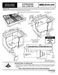
Use the following chart for correct Natural gas orifice spud for<br />
each burner. Refer to the gas information plate on the right-hand<br />
side of the bottom oven frame for proper sizing of Natural orifice<br />
spuds for each burner location.<br />
Natural Gas Orifice Spud Chart<br />
Location Burner Rating Color Number<br />
Right Front 16,000 BTU Clear 190N<br />
Right Rear 5,000 BTU Green 107N<br />
Left Front 15,000 BTU Center: Clear<br />
Outer: Clear<br />
Left Rear 9,200 BTU Clear 142N<br />
Center: 80N<br />
Outer: 165N<br />
6. Replace the LP gas orifice spud with correct Natural gas<br />
orifice spud. See the “Natural Gas Orifice Spud Chart.”<br />
7. Replace burner base and hand tighten the screws.<br />
8. Replace burner cap.<br />
9. Repeat steps 1 through 8 for the remaining burners.<br />
10. Place LP gas orifice spuds (and LP choke on models with a<br />
dual burner) in plastic parts bag for future use and keep with<br />
package containing literature.<br />
11. Replace burner grates.<br />
12. Reinstall oven door. See the “Oven Door” section of the Use<br />
and Care Guide.<br />
13. Plug in range or reconnect power.<br />
14. Complete installation. See “Make Gas Connection” and<br />
“Electronic Ignition System” sections.<br />
Checking for proper cooktop burner flame is very important.<br />
The small inner cone should have a very distinct blue flame<br />
¼" to ½" long. The outer cone is not as distinct as the inner<br />
cone. Natural gas flames do not have yellow tips.<br />
IMPORTANT: You may have to adjust the “LO” setting for<br />
each cooktop burner.<br />
27