installation instructions electric downdraft slide-in ranges ... - Jenn-Air
installation instructions electric downdraft slide-in ranges ... - Jenn-Air
installation instructions electric downdraft slide-in ranges ... - Jenn-Air

You also want an ePaper? Increase the reach of your titles
YUMPU automatically turns print PDFs into web optimized ePapers that Google loves.
INSTALLATION INSTRUCTIONS<br />
ELECTRIC DOWNDRAFT SLIDE-IN RANGES<br />
INSTRUCTIONS D’INSTALLATION<br />
DES CUISINIÈRES ÉLECTRIQUES À ÉVACUATION<br />
DESCENDANTE ENCASTRABLES<br />
RANGE SAFETY .............................................................................2<br />
INSTALLATION REQUIREMENTS ................................................3<br />
Tools and Parts ............................................................................3<br />
Location Requirements................................................................3<br />
Vent<strong>in</strong>g Requirements..................................................................5<br />
Vent<strong>in</strong>g Methods ..........................................................................5<br />
Calculat<strong>in</strong>g Vent System Length..................................................6<br />
Electrical Requirements - U.S.A. Only.........................................7<br />
Electrical Requirements - Canada Only.......................................8<br />
Countertop Preparation ...............................................................8<br />
INSTALLATION INSTRUCTIONS ..................................................9<br />
Unpack Range..............................................................................9<br />
Adjust Level<strong>in</strong>g Legs ....................................................................9<br />
Install Anti-Tip Bracket.................................................................9<br />
Install Downdraft System...........................................................10<br />
Electrical Connection - U.S.A. Only...........................................14<br />
Connect Range to Downdraft System.......................................20<br />
Verify Anti-Tip Is Installed and Engaged....................................21<br />
Complete Installation .................................................................22<br />
Mov<strong>in</strong>g the Range ......................................................................22<br />
Table of Contents/Table des matières<br />
SÉCURITÉ DE LA CUISINIÈRE ...................................................24<br />
EXIGENCES D’INSTALLATION...................................................25<br />
Outils et pièces...........................................................................25<br />
Exigences d’emplacement.........................................................25<br />
Exigences concernant l’évacuation ...........................................27<br />
Méthodes d’évacuation..............................................................28<br />
Calcul de la longueur effective du circuit<br />
d’évacuation ...............................................................................29<br />
Spécifications électriques – Canada seulement........................30<br />
Préparation du plan de travail ....................................................30<br />
INSTRUCTIONS D’INSTALLATION.............................................31<br />
Déballage de la cuis<strong>in</strong>ière ..........................................................31<br />
Réglage des pieds de nivellement .............................................31<br />
Installation de la bride antibasculement ....................................32<br />
Installation du circuit d’évacuation par le bas ...........................32<br />
Raccordement de la cuis<strong>in</strong>ière au circuit<br />
d’évacuation par le bas..............................................................36<br />
Vérifier que la bride anti-basculement est bien<br />
<strong>in</strong>stallée et engagée....................................................................38<br />
Achever l’<strong><strong>in</strong>stallation</strong> ..................................................................38<br />
Déplacement de la cuis<strong>in</strong>ière .....................................................39<br />
IMPORTANT:<br />
Save for local <strong>electric</strong>al <strong>in</strong>spector's use.<br />
IMPORTANT :<br />
À conserver pour consultation par l'<strong>in</strong>specteur local des <strong><strong>in</strong>stallation</strong>s électriques.<br />
W10430955A
RANGE SAFETY<br />
Your safety and the safety of others are very important.<br />
We have provided many important safety messages <strong>in</strong> this manual and on your appliance. Always read and obey all safety<br />
messages.<br />
This is the safety alert symbol.<br />
This symbol alerts you to potential hazards that can kill or hurt you and others.<br />
All safety messages will follow the safety alert symbol and either the word “DANGER” or “WARNING.”<br />
These words mean:<br />
DANGER<br />
You can be killed or seriously <strong>in</strong>jured if you don't immediately<br />
follow <strong><strong>in</strong>structions</strong>.<br />
WARNING<br />
You can be killed or seriously <strong>in</strong>jured if you don't follow<br />
<strong><strong>in</strong>structions</strong>.<br />
All safety messages will tell you what the potential hazard is, tell you how to reduce the chance of <strong>in</strong>jury, and tell you what can<br />
happen if the <strong><strong>in</strong>structions</strong> are not followed.<br />
WARNING<br />
Tip Over Hazard<br />
A child or adult can tip the range and be killed.<br />
Install anti-tip bracket to floor or wall per <strong><strong>in</strong>stallation</strong> <strong><strong>in</strong>structions</strong>.<br />
Slide range back so rear range foot is engaged <strong>in</strong> the slot of the anti-tip bracket.<br />
Re-engage anti-tip bracket if range is moved.<br />
Do not operate range without anti-tip bracket <strong>in</strong>stalled and engaged.<br />
Failure to follow these <strong><strong>in</strong>structions</strong> can result <strong>in</strong> death or serious burns to children and adults.<br />
Range Foot<br />
Anti-Tip<br />
Bracket<br />
To verify the anti-tip bracket is <strong>in</strong>stalled and engaged:<br />
• Slide range forward.<br />
• Look for the anti-tip bracket securely attached to floor or wall.<br />
• Slide range back so rear range foot is under anti-tip bracket.<br />
• See <strong><strong>in</strong>stallation</strong> <strong><strong>in</strong>structions</strong> for details.<br />
2
Tools and Parts<br />
Gather the required tools and parts before start<strong>in</strong>g <strong><strong>in</strong>stallation</strong>.<br />
Read and follow the <strong><strong>in</strong>structions</strong> provided with any tools listed<br />
here.<br />
Tools needed<br />
■<br />
■<br />
■<br />
■<br />
■<br />
■<br />
Parts supplied<br />
Check that all parts are <strong>in</strong>cluded.<br />
■ 3 - #10-32 hex nuts (attached to term<strong>in</strong>al block)<br />
■<br />
■<br />
■<br />
■<br />
■<br />
■<br />
■<br />
■<br />
■<br />
Tape measure<br />
Level<br />
Phillips screwdriver<br />
Flat-blade screwdriver<br />
Saber or keyhole saw<br />
Marker or pencil<br />
3 - Term<strong>in</strong>al lugs<br />
2 or 3 - Oven racks (depend<strong>in</strong>g on your model)<br />
Blower motor<br />
2 - vent clamps<br />
Flexible vent<br />
Flow tester card<br />
Blower location template<br />
4 - #8 x ¾" screws (for mount<strong>in</strong>g blower motor bracket)<br />
2 - #12 x 1⁵⁄₈" screws (for mount<strong>in</strong>g anti-tip bracket)<br />
■<br />
■<br />
■<br />
■<br />
■<br />
■<br />
■ Anti-tip bracket (taped to package conta<strong>in</strong><strong>in</strong>g literature <strong>in</strong><br />
oven cavity)<br />
Anti-tip bracket must be securely mounted to back wall or<br />
floor. Thickness of floor may require longer screws to anchor<br />
bracket to subfloor. Longer screws are available from your<br />
local hardware store.<br />
Parts needed<br />
■ One of the follow<strong>in</strong>g <strong>Jenn</strong>-<strong>Air</strong> wall caps:<br />
<strong>Jenn</strong>-<strong>Air</strong> ® 5" (12.7 cm) Round Surface Wall Cap Damper.<br />
Order Part Number A405.<br />
<strong>Jenn</strong>-<strong>Air</strong> ® 6" (15.2 cm) Round Surface Wall Cap Damper.<br />
Order Part Number A406.<br />
<strong>Jenn</strong>-<strong>Air</strong> ® 3¼" x 10" (8.3 x 25.4 cm) Surface Wall Cap<br />
Damper. Order Part Number A403.<br />
To order, see the “Assistance or Service” section of the Use<br />
and Care Guide.<br />
■ Metal duct<strong>in</strong>g<br />
■ Vent clamps<br />
■ Concrete anchors (for concrete floor mount<strong>in</strong>g)<br />
■ 2 - 2" x 4" x 8¾" (5.0 x 10.2 x 22.2 cm) wood spacers (for left<br />
or right side vent<strong>in</strong>g)<br />
INSTALLATION REQUIREMENTS<br />
Wrench or pliers<br />
⁵⁄₁₆" nut driver<br />
¼" nut driver<br />
Drill<br />
¹⁄₈" (3.2 mm) drill bit<br />
³⁄₁₆" (4.8 mm) carbide-tipped<br />
masonry drill bit (for concrete/<br />
ceramic floors)<br />
If us<strong>in</strong>g a power supply cord:<br />
■ A UL listed power supply cord kit marked for use with <strong>ranges</strong>.<br />
The cord should be rated at 250 volts m<strong>in</strong>imum, 40 amps or<br />
50 amps that is marked for use with nom<strong>in</strong>al 1³⁄₈" (3.5 cm)<br />
diameter connection open<strong>in</strong>g and must end <strong>in</strong> r<strong>in</strong>g term<strong>in</strong>als<br />
or open-end spade term<strong>in</strong>als with upturned ends.<br />
■ A UL listed stra<strong>in</strong> relief.<br />
Check local codes. Check exist<strong>in</strong>g <strong>electric</strong>al supply. See<br />
“Electrical Requirements” section.<br />
It is recommended that all <strong>electric</strong>al connections be made by a<br />
licensed, qualified <strong>electric</strong>al <strong>in</strong>staller.<br />
Location Requirements<br />
IMPORTANT: Observe all govern<strong>in</strong>g codes and ord<strong>in</strong>ances.<br />
■<br />
■<br />
■<br />
■<br />
It is the <strong>in</strong>staller’s responsibility to comply with <strong><strong>in</strong>stallation</strong><br />
clearances specified on the model/serial rat<strong>in</strong>g plate. The<br />
model/serial rat<strong>in</strong>g plate is located on the right-hand side of<br />
the oven frame beh<strong>in</strong>d the storage drawer panel.<br />
The range should be located for convenient use <strong>in</strong> the<br />
kitchen.<br />
To elim<strong>in</strong>ate the risk of burns or fire by reach<strong>in</strong>g over heated<br />
surface units, cab<strong>in</strong>et storage space located above the<br />
surface units should be avoided. If cab<strong>in</strong>et storage is to be<br />
provided, the risk can be reduced by <strong>in</strong>stall<strong>in</strong>g a range hood<br />
that projects horizontally a m<strong>in</strong>imum of 5" (12.7 cm) beyond<br />
the bottom of the cab<strong>in</strong>ets.<br />
Cab<strong>in</strong>et open<strong>in</strong>g dimensions that are shown must be used.<br />
Given dimensions are m<strong>in</strong>imum clearances.<br />
■ The floor anti-tip bracket must be <strong>in</strong>stalled. To <strong>in</strong>stall the antitip<br />
bracket shipped with the range, see “Install Anti-Tip<br />
Bracket” section.<br />
■ Grounded <strong>electric</strong>al supply is required. See “Electrical<br />
Requirements” section.<br />
IMPORTANT: To avoid damage to your cab<strong>in</strong>ets, check with your<br />
builder or cab<strong>in</strong>et supplier to make sure that the materials used<br />
will not discolor, delam<strong>in</strong>ate or susta<strong>in</strong> other damage. This oven<br />
has been designed <strong>in</strong> accordance with the requirements of UL<br />
and CSA International and complies with the maximum allowable<br />
wood cab<strong>in</strong>et temperatures of 194°F (90°C).<br />
Mobile Home - Additional Installation Requirements<br />
The <strong><strong>in</strong>stallation</strong> of this range must conform to the Manufactured<br />
Home Construction and Safety Standard, Title 24 CFR, Part 3280<br />
(formerly the Federal Standard for Mobile Home Construction<br />
and Safety, Title 24, HUD Part 280). When such standard is not<br />
applicable, the Standard for Manufactured Home Installations,<br />
ANSI A225.1/NFPA 501A or with local codes.<br />
Mobile home <strong><strong>in</strong>stallation</strong>s require:<br />
■ When this range is <strong>in</strong>stalled <strong>in</strong> a mobile home, it must be<br />
secured to the floor dur<strong>in</strong>g transit. Any method of secur<strong>in</strong>g<br />
the range is adequate as long as it conforms to the standards<br />
listed above.<br />
■ Four-wire power supply cord or cable must be used <strong>in</strong> a<br />
mobile home <strong><strong>in</strong>stallation</strong>. The appliance wir<strong>in</strong>g will need to be<br />
revised. See “Electrical Connection” section.<br />
3
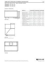
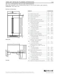
Product Dimensions<br />
Cab<strong>in</strong>et Dimensions<br />
A<br />
Cab<strong>in</strong>et open<strong>in</strong>g dimensions shown are for 25" (64.0 cm)<br />
countertop depth, 24" (61.0 cm) base cab<strong>in</strong>et depth and<br />
36" (91.4 cm) countertop height.<br />
B<br />
A<br />
C<br />
F<br />
H<br />
D<br />
B*<br />
E**<br />
E<br />
I<br />
I<br />
F<br />
D<br />
C<br />
G<br />
A. 30³⁄₄" (78.1 cm)<br />
B. 35³⁄₄" (90.8 cm) height to underside<br />
of cooktop edge with level<strong>in</strong>g legs<br />
screwed all the way <strong>in</strong>*<br />
C. Model/serial number plate (located<br />
on the right-hand side of the<br />
bottom oven frame)<br />
D. 29⁷⁄₈" (75.9 cm)<br />
E. 29¹⁄₁₆" (73.8 cm) from<br />
handle to standoff at back<br />
of range**<br />
F. 23½" (59.7 cm)<br />
countertop notch to rear<br />
of cooktop<br />
*Range can be raised approximately 1" (2.5 cm) by adjust<strong>in</strong>g<br />
the level<strong>in</strong>g legs.<br />
**When <strong>in</strong>stalled <strong>in</strong> a 24" (61 cm) base cab<strong>in</strong>et with 25" (63.5 cm)<br />
countertop; front of oven door protrudes 2¹⁄₂" (6.4 cm) beyond<br />
24" (61.0 cm) base cab<strong>in</strong>et.<br />
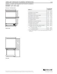
A. 13" (33.0 cm) upper cab<strong>in</strong>et<br />
depth<br />
B. 30" (76.2 cm) m<strong>in</strong>. open<strong>in</strong>g<br />
width<br />
C. For m<strong>in</strong>imum clearance to the<br />
top of the cooktop,<br />
see NOTE*.<br />
D. 23¹⁄₄" (59.1 cm) open<strong>in</strong>g<br />
depth<br />
E. 30" (76.2 cm) m<strong>in</strong>. open<strong>in</strong>g<br />
width<br />
F. Junction box - 5.5" (14.0 cm)<br />
m<strong>in</strong>. from either cab<strong>in</strong>et,<br />
10" (25.4 cm) max. from floor<br />
Outlet must be flush.<br />
Noth<strong>in</strong>g located <strong>in</strong> shaded<br />
area can extend more than<br />
2" (5.1 cm) from wall or range<br />
will not <strong>slide</strong> all the way back.<br />
G. Cab<strong>in</strong>et door or h<strong>in</strong>ge should<br />
not extend <strong>in</strong>to cutout.<br />
H. 18" (45.7 cm)<br />
I. 3" (7.6 cm) m<strong>in</strong>. clearance from<br />
both sides of the range to the<br />
side wall or other combustible<br />
material.<br />
NOTE: 24" (61.0 cm) m<strong>in</strong>imum when bottom of wood or metal<br />
cab<strong>in</strong>et is covered by not less than ¹⁄₄" (0.64 cm) flame retardant<br />
millboard covered with not less than No. 28 MSG sheet steel,<br />
0.015" (0.4 mm) sta<strong>in</strong>less steel, 0.024" (0.6 mm) alum<strong>in</strong>um or<br />
0.020" (0.5 mm) copper.<br />
30" (76.2 cm) m<strong>in</strong>imum clearance between the top of the cook<strong>in</strong>g<br />
platform and the bottom of an uncovered wood or metal cab<strong>in</strong>et.<br />
4
Vent<strong>in</strong>g Requirements<br />
IMPORTANT: This range must be exhausted outdoors. See<br />
“Vent<strong>in</strong>g Methods” section.<br />
■ Do not term<strong>in</strong>ate the vent system <strong>in</strong> an attic or other enclosed<br />
area.<br />
■ Use a <strong>Jenn</strong>-<strong>Air</strong> wall cap.<br />
■ Vent system must term<strong>in</strong>ate to the outside.<br />
■ Use only a 6" (15.2 cm) round metal vent or a 3¼ x 10"<br />
(8.3 cm x 25.4 cm) rectangular vent, except as follows:<br />
5" (12.7 cm) round metal vent may be used for vent<strong>in</strong>g<br />
straight out the back of the range and directly through the<br />
wall for vent lengths of 10 ft (3.0 m) or less.<br />
■ Rigid metal vent is recommended. For best performance, do<br />
not use plastic or metal foil vent.<br />
■ Before mak<strong>in</strong>g cutouts, make sure there is proper clearance<br />
with<strong>in</strong> the wall or floor for the exhaust vent.<br />
■ Do not cut a joist or stud unless absolutely necessary. If a<br />
joist or stud must be cut, then a support<strong>in</strong>g frame must be<br />
constructed.<br />
■ The size of the vent should be uniform.<br />
■<br />
■<br />
The vent system must have a damper. If roof or wall cap has a<br />
damper, do not use damper supplied with the range hood.<br />
Use vent clamps to seal all jo<strong>in</strong>ts <strong>in</strong> the vent system.<br />
■ Use caulk<strong>in</strong>g to seal exterior wall or roof open<strong>in</strong>g around the<br />
cap.<br />
■ Determ<strong>in</strong>e which vent<strong>in</strong>g method is best for your application.<br />
For Best Performance:<br />
■ Use 26-gauge m<strong>in</strong>imum galvanized or 25-gauge m<strong>in</strong>imum<br />
alum<strong>in</strong>um metal vent. Poor quality pipe fitt<strong>in</strong>gs can reduce<br />
airflow. Flexible metal vent is not recommended.<br />
NOTE: Local codes may require a heavier gauge material.<br />
■ Metal duct may be reduced to 30-gauge galvanized steel or<br />
26-gauge alum<strong>in</strong>ized steel if allowed by local codes. This<br />
reduction is based on <strong>in</strong>formation <strong>in</strong> the International<br />
Residential Codes Section M1601.1 (2006 edition).<br />
■ Do not <strong>in</strong>stall 2 elbows together.<br />
■ Use no more than three 90° elbows.<br />
■ If an elbow is used, <strong>in</strong>stall it as far away as possible from the<br />
hood’s vent motor exhaust open<strong>in</strong>g.<br />
■ Make sure there is a m<strong>in</strong>imum of 18" (45.7 cm) of straight<br />
vent between the elbows if more than one elbow is used.<br />
■ Elbows too close together can cause excess turbulence that<br />
reduces airflow.<br />
■ Do not use a 5" (12.7 cm) elbow <strong>in</strong> a 6" (15.2 cm) or 3¹⁄₄" x 10"<br />
(8.3 x 25.4 cm) system.<br />
■ Do not reduce to a 5" (12.7 cm) system after us<strong>in</strong>g a<br />
6" (15.2 cm) or 3¹⁄₄" x 10" (8.3 x 25.4 cm) fitt<strong>in</strong>gs.<br />
■<br />
■<br />
■<br />
■<br />
Avoid form<strong>in</strong>g handmade crimps. Handmade crimps may<br />
restrict airflow.<br />
Use a <strong>Jenn</strong>-<strong>Air</strong> vent cap for proper performance. If an<br />
alternate wall or roof cap is used, be certa<strong>in</strong> the cap size is<br />
not reduced and that it has a backdraft damper.<br />
Use vent clamps to seal all jo<strong>in</strong>ts <strong>in</strong> the vent system.<br />
Use caulk<strong>in</strong>g to seal exterior wall or roof open<strong>in</strong>g around the<br />
cap.<br />
The length of vent system and number of elbows should be kept<br />
to a m<strong>in</strong>imum to provide efficient performance.<br />
The maximum equivalent length of the vent system is<br />
60 ft (18.3 m). For altitudes above 4,500 ft (1272 m), reduce<br />
recommended vent run by 20% for best performance.<br />
Cold Weather Installations<br />
An additional backdraft damper should be <strong>in</strong>stalled to m<strong>in</strong>imize<br />
backward cold air flow and a thermal break <strong>in</strong>stalled to m<strong>in</strong>imize<br />
conduction of outside temperatures as part of the vent system.<br />
The damper should be on the cold air side of the thermal break.<br />
Makeup <strong>Air</strong><br />
Local build<strong>in</strong>g codes may require the use of makeup air systems<br />
when us<strong>in</strong>g ventilation systems greater than specified CFM of air<br />
movement. The specified CFM varies from locale to locale.<br />
Consult your HVAC professional for specific requirements <strong>in</strong> your<br />
area.<br />
Vent<strong>in</strong>g Methods<br />
Common vent<strong>in</strong>g methods are shown for a <strong>downdraft</strong> range. The<br />
<strong>downdraft</strong> range may be vented through the wall or floor.<br />
Wall Vent<strong>in</strong>g<br />
Floor Vent<strong>in</strong>g<br />
Vent<strong>in</strong>g Between Floor Joists<br />
A<br />
A<br />
B<br />
A. Wall cap<br />
B. 6" (15.2 cm) round roof vent<strong>in</strong>g<br />
B<br />
A. Wall cap<br />
B. 6" (15.2 cm) round roof vent<strong>in</strong>g<br />
5
Left or Right Side Vent<strong>in</strong>g<br />
Vent<strong>in</strong>g Beh<strong>in</strong>d Cab<strong>in</strong>et Kickplate<br />
Concrete Slab Installations - Exhaust Through Wall<br />
A<br />
A. Wall cap<br />
B. 6" (15.2 cm) round roof vent<strong>in</strong>g<br />
B<br />
D<br />
B<br />
A<br />
Calculat<strong>in</strong>g Vent System Length<br />
IMPORTANT: This range is rated at 60 ft (18.3 m) of straight duct.<br />
Low range is up to 30 ft (9.1 m); high range is 31 ft (9.4 m) to<br />
60 ft (18.3 m).<br />
If equivalent duct length exceeds 30 ft (18.3 m), the blower must<br />
be converted to high range.<br />
■ Do not convert to high range for shorter lengths. This will<br />
cause excessive noise, conditioned air loss and affect the<br />
flame pattern on gas <strong>ranges</strong>.<br />
■ To convert blower for high range <strong><strong>in</strong>stallation</strong>s, see the<br />
“Install Downdraft System” section.<br />
To calculate the length of the system you need, add the<br />
equivalent feet (meters) for each vent piece used <strong>in</strong> the system.<br />
Vent Piece<br />
45° elbow 2.5 ft<br />
(0.8 m)<br />
6" (15.2 cm) Round<br />
L<br />
C<br />
E<br />
90° elbow 5.0 ft<br />
(1.5 m)<br />
K<br />
F<br />
G<br />
J<br />
I<br />
H<br />
A. Wall cap<br />
B. 6" (15.2 cm) round metal vent<br />
C. 16" (40.6 cm) maximum<br />
D. 6" (15.2 cm) round PVC sewer pipe<br />
E. Concrete slab<br />
F. 6" (15.2 cm) round PVC sewer pipe<br />
G. 6" (15.2 cm) round 90° PVC sewer pipe elbow<br />
H. Tightly pack gravel or sand completely around pipe.<br />
I. 30 ft (9.1 m) max.<br />
J. 6" (15.2 cm) round 90° PVC sewer pipe elbow<br />
K. 6" (15.2 cm) round PVC coupl<strong>in</strong>g<br />
L. 12" (30.5 cm) m<strong>in</strong>imum<br />
Concrete Slab Installations -<br />
Exhaust Through W<strong>in</strong>dow Well<br />
IMPORTANT: W<strong>in</strong>dow well <strong><strong>in</strong>stallation</strong> for <strong>electric</strong> models only.<br />
A<br />
K<br />
B<br />
J<br />
I<br />
C<br />
H<br />
D<br />
A. Wall cap<br />
B. 12" (30.5 cm) m<strong>in</strong>imum<br />
C. Concrete slab<br />
D. 6" (15.2 cm) round PVC sewer pipe<br />
E. 6" (15.2 cm) round PVC sewer pipe<br />
F. 6" (15.2 cm) round 90° PVC sewer pipe elbow<br />
G. Tightly pack gravel or sand completely around pipe.<br />
H. 42 ft (12.8 m) max.<br />
I. 6" (15.2 cm) round PVC coupl<strong>in</strong>g<br />
J. 6" (15.2 cm) m<strong>in</strong>imum<br />
K. W<strong>in</strong>dow well<br />
E<br />
F<br />
G<br />
6" (15.2 cm)<br />
wall cap<br />
3¹⁄₄" x 10" (8.3 cm x 25.4 cm)<br />
to 6" (15.2 cm) transition<br />
6" (15.2 cm) to 3¹⁄₄" x 10"<br />
(8.3 cm x 25.4 cm) transition<br />
3¹⁄₄" x 10" (8.3 cm x 25.4 cm)<br />
to 6" (15.2 cm) 90° elbow<br />
transition<br />
6" (15.2 cm) to 3¹⁄₄" x 10"<br />
(8.3 cm x 25.4 cm) 90° elbow<br />
transition<br />
3¹⁄₄" x 10" (8.3 cm x 25.4 cm)<br />
90° elbow<br />
3¹⁄₄" x 10" (8.3 cm x 25.4 cm)<br />
flat elbow<br />
3¹⁄₄" x 10" (8.3 cm x 25.4 cm)<br />
wall cap<br />
0.0 ft<br />
(0.0 m)<br />
4.5 ft<br />
(1.4 m)<br />
1 ft<br />
(0.3 m)<br />
5.0 ft<br />
(1.5 m)<br />
5.0 ft<br />
(1.5 m)<br />
5.0 ft<br />
(1.5 m)<br />
12.0 ft<br />
(3.7 m)<br />
0.0 ft<br />
(0.0 m)<br />
6
Example vent system<br />
90˚ elbow<br />
6 ft (1.8 m)<br />
wall cap<br />
Range Rat<strong>in</strong>g*<br />
120/240 Volts 120/208 Volts Amps<br />
Specified Rat<strong>in</strong>g of<br />
Power Supply Cord Kit<br />
and Circuit Protection<br />
8.8 - 16.5 KW<br />
16.6 - 22.5 KW<br />
7.8 - 12.5 KW<br />
12.6 - 18.5 KW<br />
40 or 50**<br />
50<br />
2 ft<br />
(0.6 m)<br />
Maximum length = 60 ft (18.3 m)<br />
1- 90° elbow = 5 ft (1.5 m)<br />
8 ft (2.4 m) straight = 8 ft (2.4 m)<br />
1 - wall cap = 0 ft (0 m)<br />
System length = 13 ft (3.9 m)<br />
NOTE: For external vent<strong>in</strong>g, flexible vent is not recommended.<br />
Flexible vent creates back pressure and air turbulence that<br />
greatly reduce performance.<br />
Electrical Requirements - U.S.A. Only<br />
If codes permit and a separate ground wire is used, it is<br />
recommended that a qualified <strong>electric</strong>al <strong>in</strong>staller determ<strong>in</strong>e that<br />
the ground path and wire gauge are <strong>in</strong> accordance with local<br />
codes.<br />
Do not use an extension cord.<br />
Be sure that the <strong>electric</strong>al connection and wire size are adequate<br />
and <strong>in</strong> conformance with the National Electrical Code, ANSI/<br />
NFPA 70-latest edition and all local codes and ord<strong>in</strong>ances.<br />
A copy of the above code standards can be obta<strong>in</strong>ed from:<br />
National Fire Protection Association<br />
1 Batterymarch Park<br />
Qu<strong>in</strong>cy, MA 02169-7471<br />
WARNING: Improper connection of the equipment-ground<strong>in</strong>g<br />
conductor can result <strong>in</strong> a risk of <strong>electric</strong> shock. Check with a<br />
qualified <strong>electric</strong>ian or service technician if you are <strong>in</strong> doubt as to<br />
whether the appliance is properly grounded. Do not modify the<br />
power supply cord plug. If it will not fit the outlet, have a proper<br />
outlet <strong>in</strong>stalled by a qualified <strong>electric</strong>ian.<br />
Electrical Connection<br />
To properly <strong>in</strong>stall your range, you must determ<strong>in</strong>e the type of<br />
<strong>electric</strong>al connection you will be us<strong>in</strong>g and follow the <strong><strong>in</strong>structions</strong><br />
provided for it here.<br />
■ Range must be connected to the proper <strong>electric</strong>al voltage<br />
and frequency as specified on the model/serial number rat<strong>in</strong>g<br />
plate. The model/serial number rat<strong>in</strong>g plate is located beh<strong>in</strong>d<br />
the control panel or on the oven frame beh<strong>in</strong>d the storage<br />
drawer panel. Refer to the figures <strong>in</strong> the “Product<br />
Dimensions” section of the “Location Requirements” section.<br />
■ This range is manufactured with the neutral term<strong>in</strong>al<br />
connected to the cab<strong>in</strong>et. Use a 3-wire, UL listed, 40- or<br />
50-amp power supply cord (pigtail) (see follow<strong>in</strong>g Range<br />
Rat<strong>in</strong>g chart). If local codes do not permit ground through the<br />
neutral, use a 4-wire power supply cord rated at 250 volts,<br />
40 or 50 amps and <strong>in</strong>vestigated for use with <strong>ranges</strong>.<br />
*The NEC calculated load is less than the total connected load<br />
listed on the model/serial rat<strong>in</strong>g plate.<br />
**If connect<strong>in</strong>g to a 50-amp circuit, use a 50-amp rated cord with<br />
kit. For 50-amp rated cord kits, use kits that specify use with a<br />
nom<strong>in</strong>al 1³⁄₈" (34.9 mm) diameter connection open<strong>in</strong>g.<br />
■ A circuit breaker is recommended.<br />
■<br />
■<br />
■<br />
■<br />
■<br />
The range can be connected directly to the circuit breaker<br />
box (or fused disconnect) through flexible or nonmetallic<br />
sheathed, copper or alum<strong>in</strong>um cable. See “Electrical<br />
Connection.”<br />
Allow 2 to 3 ft (61.0 cm to 91.4 cm) of slack <strong>in</strong> the l<strong>in</strong>e so that<br />
the range can be moved if servic<strong>in</strong>g is ever necessary.<br />
A UL listed conduit connector must be provided at each end<br />
of the power supply cable (at the range and at the junction<br />
box).<br />
Wire sizes and connections must conform with the rat<strong>in</strong>g of<br />
the range.<br />
The wir<strong>in</strong>g diagram is located on the back of the access<br />
panel <strong>in</strong> a plastic bag.<br />
If connect<strong>in</strong>g to a 4-wire system:<br />
This range is manufactured with the ground connected to the<br />
neutral by a l<strong>in</strong>k. The ground must be revised so the green<br />
ground wire of the 4-wire power supply cord is connected to the<br />
cab<strong>in</strong>et. See “Electrical Connection.”<br />
Ground<strong>in</strong>g through the neutral conductor is prohibited for new<br />
branch-circuit <strong><strong>in</strong>stallation</strong>s (1996 NEC); mobile homes; and<br />
recreational vehicles, or an area where local codes prohibit<br />
ground<strong>in</strong>g through the neutral conductor.<br />
When a 4-wire receptacle of NEMA Type 14-50R is used, a<br />
match<strong>in</strong>g UL listed, 4-wire, 250-volt, 40- or 50-amp, range power<br />
supply cord (pigtail) must be used. This cord conta<strong>in</strong>s 4 copper<br />
conductors with r<strong>in</strong>g term<strong>in</strong>als or open-end spade term<strong>in</strong>als with<br />
upturned ends, term<strong>in</strong>at<strong>in</strong>g <strong>in</strong> a NEMA Type 14-50P plug on the<br />
supply end.<br />
The fourth (ground<strong>in</strong>g) conductor must be identified by a green or<br />
green/yellow cover and the neutral conductor by a white cover.<br />
Cord should be Type SRD or SRDT with a UL listed stra<strong>in</strong> relief<br />
and be at least 4 ft (1.22 m) long.<br />
4-wire receptacle (14-50R)<br />
The m<strong>in</strong>imum conductor sized for the copper 4-wire power<br />
cord are:<br />
40-amp circuit<br />
2 No.-8 conductors<br />
1 No.-10 white neutral<br />
1 No.-8 green ground<strong>in</strong>g<br />
7
If connect<strong>in</strong>g to a 3-wire system:<br />
Local codes may permit the use of a UL listed, 3-wire, 250-volt,<br />
40- or 50-amp range power supply cord (pigtail). This cord<br />
conta<strong>in</strong>s 3 copper conductors with r<strong>in</strong>g term<strong>in</strong>als or open-end<br />
spade term<strong>in</strong>als with upturned ends, term<strong>in</strong>at<strong>in</strong>g <strong>in</strong> a NEMA Type<br />
10-50P plug on the supply end. Connectors on the appliance end<br />
must be provided at the po<strong>in</strong>t the power supply cord enters the<br />
appliance. This uses a 3-wire receptacle of NEMA Type 10-50R.<br />
■<br />
■<br />
A time-delay fuse or circuit breaker is recommended.<br />
This range is equipped with a CSA International Certified<br />
Power Cord <strong>in</strong>tended to be plugged <strong>in</strong>to a standard 14-50R<br />
wall receptacle. Be sure the wall receptacle is with<strong>in</strong> reach of<br />
range’s f<strong>in</strong>al location.<br />
■<br />
Do not use an extension cord.<br />
3-wire receptacle (10-50R)<br />
Electrical Requirements - Canada Only<br />
WARNING<br />
Countertop Preparation<br />
(for Slide-<strong>in</strong> Ranges Only)<br />
The cooktop sides of the <strong>slide</strong>-<strong>in</strong> range fit over the cutout edge of<br />
your countertop.<br />
If you have a square f<strong>in</strong>ish (flat) countertop and the open<strong>in</strong>g width<br />
is 30" (76.2 cm), no countertop preparation is required.<br />
Formed front-edged countertops must have molded edge<br />
shaved flat ³⁄₈" (1.0 cm) from each front corner of open<strong>in</strong>g.<br />
Tile countertops may need trim cut back ³⁄₈" (1.0 cm) from each<br />
front corner and/or rounded edge flattened.<br />
Electrical Shock Hazard<br />
Electrically ground range.<br />
Failure to do so can result <strong>in</strong> death, fire, or<br />
<strong>electric</strong>al shock.<br />
If codes permit and a separate ground wire is used, it is<br />
recommended that a qualified <strong>electric</strong>al <strong>in</strong>staller determ<strong>in</strong>e that<br />
the ground path is adequate and wire gauge are <strong>in</strong> accordance<br />
with local codes.<br />
Be sure that the <strong>electric</strong>al connection and wire size are adequate<br />
and <strong>in</strong> conformance with CSA Standard C22.1, Canadian<br />
Electrical Code, Part 1 - latest edition, and all local codes and<br />
ord<strong>in</strong>ances.<br />
A copy of the above code standards can be obta<strong>in</strong>ed from:<br />
Canadian Standards Association<br />
178 Rexdale Blvd.<br />
Toronto, ON M9W 1R3 CANADA<br />
■ Check with a qualified <strong>electric</strong>al <strong>in</strong>staller if you are not sure<br />
the range is properly grounded.<br />
30"<br />
(76.2 cm)<br />
30 ¾"<br />
(78.1 cm)<br />
³⁄₈"<br />
(1.0 cm)<br />
If countertop open<strong>in</strong>g width is greater than 30" (76.2 cm), adjust<br />
the ³⁄₈" (1.0 cm) dimension.<br />
Countertop must be level. Place level on countertop, first side to<br />
side, then front to back. If countertop is not level, range will not<br />
be level. Range must be level for satisfactory bak<strong>in</strong>g conditions.<br />
Range Rat<strong>in</strong>g*<br />
120/240 Volts 120/208 Volts Amps<br />
8.8 - 16.5 KW<br />
16.6 - 22.5 KW<br />
7.8 - 12.5 KW<br />
12.6 - 18.5 KW<br />
Specified Rat<strong>in</strong>g of<br />
Power Supply Cord Kit<br />
and Circuit Protection<br />
40 or 50<br />
50<br />
*The NEC calculated load is less than the total connected load<br />
listed on the model/serial rat<strong>in</strong>g plate.<br />
8
INSTALLATION INSTRUCTIONS<br />
Unpack Range<br />
WARNING<br />
Excessive Weight Hazard<br />
Use two or more people to move and <strong>in</strong>stall range.<br />
Failure to do so can result <strong>in</strong> back or other <strong>in</strong>jury.<br />
Install Anti-Tip Bracket<br />
WARNING<br />
1. Remove shipp<strong>in</strong>g materials, tape and film from the range.<br />
Keep cardboard bottom under range.<br />
2. Remove oven racks and parts package from <strong>in</strong>side oven.<br />
3. To remove cardboard bottom, place range on its back, take<br />
4 cardboard corners from the carton. Stack one cardboard<br />
corner on top of another. Repeat with the other 2 corners.<br />
Place them lengthwise on the floor beh<strong>in</strong>d the range to<br />
support the range when it is laid on its back.<br />
4. Us<strong>in</strong>g 2 or more people, firmly grasp the range and gently lay<br />
it on its back on the cardboard corners.<br />
5. Pull cardboard bottom firmly to remove.<br />
6. Use an adjustable wrench to loosen the level<strong>in</strong>g legs.<br />
7. Place cardboard or hardboard <strong>in</strong> front of range. Us<strong>in</strong>g 2 or<br />
more people, stand range back up onto cardboard or<br />
hardboard.<br />
Adjust Level<strong>in</strong>g Legs<br />
1. If range height adjustment is necessary, use a wrench or<br />
pliers to loosen the 4 level<strong>in</strong>g legs.<br />
This may be done with the range on its back or with the range<br />
supported on 2 legs after the range has been placed back to<br />
a stand<strong>in</strong>g position.<br />
NOTE: To place range back up <strong>in</strong>to a stand<strong>in</strong>g position, put a<br />
sheet of cardboard or hardboard <strong>in</strong> front of range. Us<strong>in</strong>g 2 or<br />
more people, stand range back up onto the cardboard or<br />
hardboard.<br />
2. Adjust the level<strong>in</strong>g legs to the correct height. Level<strong>in</strong>g legs<br />
can be loosened to add up to a maximum of 1" (2.5 cm). A<br />
m<strong>in</strong>imum of ³⁄₁₆" (5 mm) is needed to engage the anti-tip<br />
bracket.<br />
NOTE: If height adjustment is made when range is stand<strong>in</strong>g,<br />
tilt the range back to adjust the front legs, then tilt forward to<br />
adjust the rear legs.<br />
3. When the range is at the correct height, check that there is<br />
adequate clearance under the range for the anti-tip bracket.<br />
Before slid<strong>in</strong>g range <strong>in</strong>to its f<strong>in</strong>al location, check that the antitip<br />
bracket will <strong>slide</strong> under the range and onto the rear<br />
level<strong>in</strong>g leg prior to anti-tip bracket <strong><strong>in</strong>stallation</strong>.<br />
Tip Over Hazard<br />
A child or adult can tip the range and be killed.<br />
Install anti-tip bracket to floor or wall per <strong><strong>in</strong>stallation</strong><br />
<strong><strong>in</strong>structions</strong>.<br />
Slide range back so rear range foot is engaged <strong>in</strong> the<br />
slot of the anti-tip bracket.<br />
Re-engage anti-tip bracket if range is moved.<br />
Do not operate range without anti-tip bracket <strong>in</strong>stalled<br />
and engaged.<br />
Failure to follow these <strong><strong>in</strong>structions</strong> can result <strong>in</strong> death<br />
or serious burns to children and adults.<br />
1. Remove the anti-tip bracket that is taped to the package<br />
conta<strong>in</strong><strong>in</strong>g literature.<br />
2. Determ<strong>in</strong>e which mount<strong>in</strong>g method to use: floor or wall.<br />
If you have a stone or masonry floor you can use the wall<br />
mount<strong>in</strong>g method.<br />
3. Determ<strong>in</strong>e and mark centerl<strong>in</strong>e of the cutout space. The<br />
mount<strong>in</strong>g bracket can be <strong>in</strong>stalled on either the left side or<br />
right side of the cutout. Position mount<strong>in</strong>g bracket <strong>in</strong> cutout<br />
so that right (or left) edge of the bracket is 14¹⁄₄" (36.2 cm)<br />
from centerl<strong>in</strong>e, as shown.<br />
A<br />
B<br />
A. Centerl<strong>in</strong>e<br />
B. 14¹⁄₄" (36.2 cm)<br />
9
4. Drill two ¹⁄₈" (3.0 mm) holes that correspond to the bracket<br />
holes of the determ<strong>in</strong>ed mount<strong>in</strong>g method. See below.<br />
Floor Mount<strong>in</strong>g<br />
A<br />
B<br />
Wall Mount<strong>in</strong>g<br />
Rear Wall Vent<strong>in</strong>g<br />
1. Mark the wall at the center of the cab<strong>in</strong>et open<strong>in</strong>g.<br />
A<br />
B<br />
A. #12 x 1⁵⁄₈" screws<br />
B. Anti-tip bracket<br />
A. #12 x 1⁵⁄₈" screws<br />
B. Anti-tip bracket<br />
5. Us<strong>in</strong>g the Phillips screwdriver, mount anti-tip bracket to the<br />
wall or floor with the two #12 x 1⁵⁄₈" screws provided.<br />
Install Downdraft System<br />
Determ<strong>in</strong>e Equivalent Length of Vent System<br />
This range is equipped with a dual range blower. It is shipped<br />
from the factory for Low Range <strong><strong>in</strong>stallation</strong>s. If vent system<br />
equivalent length exceeds 30 ft (9.1 m), the <strong>downdraft</strong> blower<br />
motor must be converted to High Range for best performance.<br />
See “Calculat<strong>in</strong>g Vent System Length.”<br />
To Convert:<br />
Gently remove the spr<strong>in</strong>g loaded Restricter R<strong>in</strong>g from the blower<br />
<strong>in</strong>let by press<strong>in</strong>g one of the 3 spr<strong>in</strong>gs.<br />
2. Check for obstructions before mark<strong>in</strong>g the vent hole location.<br />
Mark a horizontal l<strong>in</strong>e 8³⁄₁₆" (20.8 cm) from the floor. Mark a<br />
vertical l<strong>in</strong>e up to a maximum of 2¼" (7.9 cm) from the right<br />
side of the cab<strong>in</strong>et centerl<strong>in</strong>e.<br />
A<br />
B<br />
A. Maximum 2¼" (7.9 cm) from<br />
the right of center<br />
B. 8³⁄₁₆" (20.8 cm) from floor<br />
3. Draw and cut a 6¼" (15.8 cm) diameter hole.<br />
A<br />
B<br />
A<br />
A. Restricter r<strong>in</strong>g<br />
B. Spr<strong>in</strong>g<br />
Determ<strong>in</strong>e which vent<strong>in</strong>g method to use: floor, rear wall, or left or<br />
right side vent<strong>in</strong>g. Go to the section for your type of vent<strong>in</strong>g.<br />
Avoid sever<strong>in</strong>g <strong>electric</strong>al wir<strong>in</strong>g when cutt<strong>in</strong>g <strong>in</strong>to floor or wall.<br />
A. 6¼" (15.8 cm)<br />
10
4. Position blower motor <strong>in</strong> cab<strong>in</strong>et open<strong>in</strong>g. Connect vent<br />
system to blower motor outlet us<strong>in</strong>g a vent clamp.<br />
A<br />
Top View<br />
B<br />
C<br />
E<br />
D<br />
3. Determ<strong>in</strong>e the correct position for the vent hole, depend<strong>in</strong>g<br />
on obstructions (joists) <strong>in</strong> the floor.<br />
The hole can be cut anywhere with<strong>in</strong> the boundaries of either<br />
hatched area.<br />
Option 1: If you are us<strong>in</strong>g the back hatched area (bigger one),<br />
the blower <strong>in</strong>let must face the left side as shown on the<br />
template<br />
Option 2: If you are us<strong>in</strong>g the front hatched area (smaller one),<br />
the blower <strong>in</strong>let must face the back.<br />
Top View<br />
Option 1 Option 2<br />
B<br />
A. 18¾" (47.6 cm) maximum from back<br />
wall forward <strong>in</strong>to cab<strong>in</strong>et open<strong>in</strong>g<br />
B. Inlet<br />
C. Vent system<br />
D. Vent clamp<br />
E. Wall vent<br />
5. Mount blower motor to the floor with 4 - #8 x ¾" hex head<br />
screws provided.<br />
Top View<br />
A<br />
A<br />
B<br />
A. Inlet from range<br />
B. Exhaust outlet<br />
NOTE: If the template is misplaced, the follow<strong>in</strong>g<br />
measurements can be used to determ<strong>in</strong>e the vent hole<br />
location.<br />
Top View<br />
B<br />
C<br />
D<br />
6. Go to the “Electrical Connection” section.<br />
Floor Vent<strong>in</strong>g<br />
1. Mark the floor at the center of the cab<strong>in</strong>et open<strong>in</strong>g.<br />
A<br />
E<br />
I<br />
H<br />
F<br />
G<br />
A. 9" (22.8 cm)<br />
B. 3¹⁄₈" (7.9 cm)<br />
C. 8³⁄₈" (21.3 cm)<br />
D. 6³⁄₈" (16.2 cm)<br />
E. 2¼" (5.7 cm)<br />
F. 12½" (31.7 cm)<br />
G. 18¾" (47.6 cm)<br />
H. 1½" (3.8 cm)<br />
I. 3½" (8.9 cm)<br />
2. Position template on floor by match<strong>in</strong>g the centerl<strong>in</strong>e of the<br />
template to the centerl<strong>in</strong>e drawn on the floor and place<br />
template 2¼" (5.7 cm) from the back wall.<br />
11
4. Draw and cut a 6¼" (15.8 cm) diameter hole (option 1 shown).<br />
Left or Right Side Vent<strong>in</strong>g<br />
1. Mark cab<strong>in</strong>et side for either a left or right side vent hole<br />
location.<br />
A<br />
B<br />
A<br />
B<br />
A. Option 1<br />
B. Option 2<br />
5. Position blower motor <strong>in</strong> cab<strong>in</strong>et open<strong>in</strong>g and mount blower<br />
motor to the floor.<br />
Top View<br />
Option 1 Option 2<br />
A. 31³⁄₁₆" (79.2 cm) to top of cab<strong>in</strong>et<br />
B. 18" (45.7 cm) from back wall<br />
2. Mark and cut a 5½" (13.9 cm) diameter hole <strong>in</strong> the desired<br />
cab<strong>in</strong>et side.<br />
B<br />
A<br />
A<br />
A<br />
B<br />
A. 5½" (13.9 cm) diameter hole<br />
A. Inlet from range<br />
B. Exhaust outlet<br />
3. Mark and cut a 14" x 11" (35.6 x 27.9 cm) open<strong>in</strong>g <strong>in</strong> the floor<br />
of the same cab<strong>in</strong>et as the vent hole open<strong>in</strong>g.<br />
Top View<br />
6. Connect vent system to blower motor outlet (option 1 shown)<br />
with 4 - #8 x ¾" hex head screws provided.<br />
A<br />
A<br />
B<br />
B<br />
C<br />
D<br />
A. Inlet<br />
B. Vent clamp<br />
C. Floor<br />
D. Vent system<br />
A. 11" (27.9 cm) from front of cab<strong>in</strong>et<br />
B. 14" (35.6 cm) from left side of cab<strong>in</strong>et<br />
7. Go to the “Electrical Connection” section.<br />
12
4. Remove 4 locknuts on the motor side of the blower and<br />
remove the bracket.<br />
View from Motor Side of Blower<br />
8. Position 2 wood spacers and mount them to the floor.<br />
Top View<br />
A<br />
B<br />
C<br />
A<br />
D D<br />
A. Electrical connector<br />
5. Lift and rotate the motor 180° to reposition the <strong>electric</strong>al<br />
connection.<br />
A. Electrical connector<br />
6. Rotate bracket 180° and secure with 4 locknuts.<br />
A<br />
A. 2" x 4" (5.0 x 10.2 cm) wood spacers<br />
B. 2⁷⁄₉" (7.3 cm) from back wall to edge of wood spacer<br />
C. 8¾" (22.2 cm)<br />
D. 2⁵⁄₁₆" (5.8 cm) centerl<strong>in</strong>e of open<strong>in</strong>g to wood spacer<br />
9. Mount blower motor to wood spacers us<strong>in</strong>g 4 - #8 x ¾" hex<br />
head screws provided.<br />
NOTE: Vent system will be connected after range has been<br />
moved <strong>in</strong>to it’s f<strong>in</strong>al location. “See Connect Range to<br />
Downdraft System” section.<br />
B<br />
Top View<br />
C<br />
A<br />
7. Remove the bracket from the other side of the blower motor,<br />
rotate 180° and secure with 4 locknuts.<br />
A. Wood spacers<br />
B. Mount<strong>in</strong>g bracket<br />
C. Blower<br />
10. Go to the “Electrical Connection” section.<br />
13
Power Supply Cord<br />
Electrical Connection - U.S.A. Only<br />
Direct Wire<br />
WARNING<br />
WARNING<br />
Electrical Shock Hazard<br />
Disconnect power before servic<strong>in</strong>g.<br />
Use a new 40 amp power supply cord.<br />
Plug <strong>in</strong>to a grounded outlet.<br />
Failure to follow these <strong><strong>in</strong>structions</strong> can result <strong>in</strong> death,<br />
fire, or <strong>electric</strong>al shock.<br />
Electrical Shock Hazard<br />
Disconnect power before servic<strong>in</strong>g.<br />
Use 8 gauge copper or 6 gauge alum<strong>in</strong>um wire.<br />
Electrically ground range.<br />
Failure to follow these <strong><strong>in</strong>structions</strong> can result <strong>in</strong> death,<br />
fire, or <strong>electric</strong>al shock.<br />
1. Disconnect power.<br />
2. Use Phillips screwdriver to remove the term<strong>in</strong>al block cover<br />
screw located on the back of the range. Pull cover down and<br />
toward you to remove cover.<br />
Style 1: Power supply cord stra<strong>in</strong> relief<br />
■<br />
Assemble a UL listed stra<strong>in</strong> relief <strong>in</strong> the open<strong>in</strong>g.<br />
A<br />
3. Remove plastic tag hold<strong>in</strong>g three 10-32 hex nuts from the<br />
middle post of the term<strong>in</strong>al block.<br />
A. UL listed stra<strong>in</strong> relief<br />
■<br />
■<br />
Feed the power supply cord through the open<strong>in</strong>g <strong>in</strong> the<br />
cord/conduit plate on bottom of range. Allow enough<br />
slack to easily attach the wir<strong>in</strong>g to the term<strong>in</strong>al block.<br />
Tighten stra<strong>in</strong> relief screw aga<strong>in</strong>st the power supply cord.<br />
4. Add stra<strong>in</strong> relief.<br />
14
REMOVE TAG! USE<br />
NUTS WITH POWER CORD<br />
QUITE LA ETIQUETA<br />
USE LAS TUERCAS<br />
PARA CONECTAR EL<br />
CORDÓN ELÉCTRICO<br />
REMOVE TAG! USE<br />
NUTS WITH POWER CORD<br />
QUITE LA ETIQUETA<br />
USE LAS TUERCAS<br />
PARA CONECTAR EL<br />
CORDÓN ELÉCTRICO<br />
Style 2: Direct wire stra<strong>in</strong> relief<br />
■<br />
Use Phillips screwdriver to remove screws from panel on<br />
back of range.<br />
■<br />
Position cord/conduit plate as shown <strong>in</strong> the follow<strong>in</strong>g<br />
illustration.<br />
■<br />
Replace cord/conduit plate and <strong>in</strong>sert screws.<br />
■<br />
Lift range back panel up and off.<br />
■<br />
Assemble a UL listed conduit connector <strong>in</strong> the open<strong>in</strong>g.<br />
■<br />
Use Phillips screwdriver to remove screws and <strong>slide</strong><br />
cord/conduit plate down and out.<br />
A<br />
B<br />
A. Removable reta<strong>in</strong><strong>in</strong>g nut<br />
B. Stra<strong>in</strong> relief<br />
■<br />
■<br />
Feed the flexible conduit through the stra<strong>in</strong> relief, allow<strong>in</strong>g<br />
enough slack to easily attach wir<strong>in</strong>g to the term<strong>in</strong>al block.<br />
Tighten stra<strong>in</strong> relief screw aga<strong>in</strong>st the flexible conduit.<br />
5. Replace back panel and screws on rear of range.<br />
6. Complete <strong><strong>in</strong>stallation</strong> follow<strong>in</strong>g <strong><strong>in</strong>structions</strong> for your type of<br />
<strong>electric</strong>al connection:<br />
4-wire (recommended)<br />
3-wire (if 4-wire is not available)<br />
15
Electrical Connection Options<br />
If your home has:<br />
4-wire receptacle<br />
(NEMA type 14-50R)<br />
And you will be<br />
connect<strong>in</strong>g to:<br />
A UL listed,<br />
250-volt<br />
m<strong>in</strong>imum,<br />
40-amp, range<br />
power supply<br />
cord<br />
Go to Section:<br />
4-wire connection:<br />
Power supply cord<br />
3. Feed the power supply cord through the open<strong>in</strong>g <strong>in</strong> the cord/<br />
conduit plate on bottom of range. Allow enough slack to<br />
easily attach the wir<strong>in</strong>g to the term<strong>in</strong>al block.<br />
A<br />
4-wire direct<br />
5"<br />
(12.7 cm)<br />
A fused<br />
disconnect or<br />
circuit breaker<br />
box<br />
4-wire connection:<br />
Direct wire<br />
B<br />
3-wire receptacle<br />
(NEMA type 10-50R)<br />
A UL listed,<br />
250-volt<br />
m<strong>in</strong>imum,<br />
40-amp, range<br />
power supply<br />
cord<br />
3-wire connection:<br />
Power supply cord<br />
C<br />
D<br />
3-wire direct<br />
1"<br />
(2.5 cm)<br />
3"<br />
(7.6 cm)<br />
A fused<br />
disconnect or<br />
circuit breaker<br />
box<br />
4-wire connection: Power Supply Cord<br />
3-wire connection:<br />
Direct wire<br />
A. Term<strong>in</strong>al block<br />
B. Ground-l<strong>in</strong>k screw<br />
C. Cord/conduit plate<br />
D. Power supply cord wires<br />
4. Use Phillips screwdriver to connect the green ground wire<br />
from the power supply cord to the range with the ground-l<strong>in</strong>k<br />
screw. The ground wire must be attached first.<br />
5. Use ³⁄₈" nut driver to connect the neutral (white) wire to the<br />
center term<strong>in</strong>al block post with one of the 10–32 hex nuts.<br />
Use this method for:<br />
■ New branch-circuit <strong><strong>in</strong>stallation</strong>s (1996 NEC)<br />
■<br />
■<br />
■<br />
Mobile homes<br />
Recreational vehicles<br />
In an area where local codes prohibit ground<strong>in</strong>g through the<br />
neutral<br />
A<br />
B<br />
F<br />
1. Part of metal ground strap must be cut out and removed.<br />
C<br />
E<br />
A. Metal ground strap<br />
B. Discard<br />
C. Ground-l<strong>in</strong>k screw<br />
2. Use Phillips screwdriver to remove the ground-l<strong>in</strong>k screw<br />
from the back of the range. Save the ground-l<strong>in</strong>k screw and<br />
the end of the ground-l<strong>in</strong>k under the screw.<br />
A<br />
B<br />
C<br />
A. 10–32 hex nut<br />
B. Ground-l<strong>in</strong>k screw<br />
C. L<strong>in</strong>e 1 (black)<br />
D<br />
D. Green ground wire<br />
E. Neutral (center) wire<br />
F. L<strong>in</strong>e 2 (red)<br />
6. Connect l<strong>in</strong>e 1 (black) and l<strong>in</strong>e 2 (red) wires to the outer<br />
term<strong>in</strong>al block posts with 10-32 hex nuts.<br />
7. Securely tighten hex nuts.<br />
NOTE: For power supply cord replacement, only use a power<br />
cord rated at 250 volts m<strong>in</strong>imum, 40 amps or 50 amps that is<br />
marked for use with nom<strong>in</strong>al 1³⁄₈" (3.5 cm) diameter<br />
connection open<strong>in</strong>g, with r<strong>in</strong>g term<strong>in</strong>als and marked for use<br />
with <strong>ranges</strong>.<br />
8. Replace term<strong>in</strong>al block access cover.<br />
16
3-wire connection: Power Supply Cord<br />
Use this method only if local codes permit connect<strong>in</strong>g chassis<br />
ground conductor to neutral wire of power supply cord.<br />
1. Feed the power supply cord through the open<strong>in</strong>g <strong>in</strong> the cord/<br />
conduit plate on bottom of range. Allow enough slack to<br />
easily attach the wir<strong>in</strong>g to the term<strong>in</strong>al block.<br />
Direct Wire Installation: Copper or Alum<strong>in</strong>um Wire<br />
This range may be connected directly to the fuse disconnect or<br />
circuit breaker box. Depend<strong>in</strong>g on your <strong>electric</strong>al supply, make<br />
the required 3-wire or 4-wire connection.<br />
1. Strip outer cover<strong>in</strong>g back 3" (7.6 cm) to expose wires. Strip<br />
the <strong>in</strong>sulation back 1" (2.5 cm) from the end of each wire.<br />
1"<br />
(2.5 cm)<br />
A<br />
3"<br />
(7.6 cm)<br />
B<br />
2. Allow enough slack <strong>in</strong> the wire to easily attach the wir<strong>in</strong>g<br />
term<strong>in</strong>al block.<br />
3. Complete <strong>electric</strong>al connection accord<strong>in</strong>g to your type of<br />
<strong>electric</strong>al supply (4-wire or 3-wire connection).<br />
4-wire Connection: Direct Wire<br />
C<br />
A. Term<strong>in</strong>al block<br />
B. Ground-l<strong>in</strong>k screw<br />
C. Cord/conduit plate<br />
D. Power supply cord wires<br />
2. Use ³⁄₈" nut driver to connect the neutral (white) wire to the<br />
center term<strong>in</strong>al block post with one of the 10–32 hex nuts.<br />
D<br />
Use this method for:<br />
■ New branch-circuit <strong><strong>in</strong>stallation</strong>s (1996 NEC)<br />
■ Mobile homes<br />
■ Recreational vehicles<br />
■ In an area where local codes prohibit ground<strong>in</strong>g through the<br />
neutral<br />
1. Part of metal ground strap must be cut out and removed.<br />
A<br />
E<br />
A<br />
B<br />
C<br />
B<br />
C<br />
A. 10–32 hex nut<br />
B. L<strong>in</strong>e 1 (black)<br />
C. Ground-l<strong>in</strong>k screw<br />
D<br />
D. Neutral (white) wire<br />
E. L<strong>in</strong>e 2 (red)<br />
A. Metal ground strap<br />
B. Discard<br />
C. Ground-l<strong>in</strong>k screw<br />
2. Use Phillips screwdriver to remove the ground-l<strong>in</strong>k screw<br />
from the back of the range. Save the ground-l<strong>in</strong>k screw and<br />
the end of the ground-l<strong>in</strong>k under the screw.<br />
3. Connect l<strong>in</strong>e 1 (black) and l<strong>in</strong>e 2 (red) wires to the outer<br />
term<strong>in</strong>al block posts with 10-32 hex nuts.<br />
4. Securely tighten hex nuts.<br />
NOTE: For power supply cord replacement, only use a power<br />
cord rated at 250 volts m<strong>in</strong>imum, 40 amps or 50 amps that is<br />
marked for use with nom<strong>in</strong>al 1³⁄₈" (3.5 cm) diameter<br />
connection open<strong>in</strong>g, with r<strong>in</strong>g term<strong>in</strong>als and marked for use<br />
with <strong>ranges</strong>.<br />
5. Replace term<strong>in</strong>al block access cover.<br />
17
3. Pull the conduit through the stra<strong>in</strong> relief on cord/conduit plate<br />
on bottom of range. Allow enough slack to easily attach<br />
wir<strong>in</strong>g to the term<strong>in</strong>al block.<br />
6. Use ³⁄₈" nut driver to connect the neutral (white) wire to the<br />
center term<strong>in</strong>al block post with one of the 10–32 hex nuts.<br />
A<br />
A<br />
G<br />
B<br />
G<br />
F<br />
A. Term<strong>in</strong>al block<br />
B. Ground-l<strong>in</strong>k screw<br />
C. Cord/conduit plate<br />
D. L<strong>in</strong>e 2 (red) wire<br />
E<br />
E. Neutral (white) wire<br />
F. L<strong>in</strong>e 1 (black) wire<br />
G. Bare (green) ground wire<br />
4. Attach term<strong>in</strong>al lugs to l<strong>in</strong>e 1 (black), neutral (white), and l<strong>in</strong>e 2<br />
(red) wires. Loosen (do not remove) the setscrew on the front<br />
of the term<strong>in</strong>al lug and <strong>in</strong>sert exposed wire end through<br />
bottom of term<strong>in</strong>al lugs. Securely tighten set screw to torque<br />
as shown <strong>in</strong> the follow<strong>in</strong>g Bare Wire Torque Specifications<br />
chart.<br />
A<br />
D<br />
B<br />
C<br />
C<br />
A. 10–32 hex nut<br />
B. L<strong>in</strong>e 1 (black)<br />
C. Bare (green) ground wire<br />
D. Ground-l<strong>in</strong>k screw<br />
7. Connect l<strong>in</strong>e 1 (black) and l<strong>in</strong>e 2 (red) wires to the outer<br />
term<strong>in</strong>al block posts with 10-32 hex nuts.<br />
8. Securely tighten hex nuts.<br />
9. Replace term<strong>in</strong>al block access cover.<br />
3-wire connection: Direct Wire<br />
Use this method only if local codes permit connect<strong>in</strong>g ground<br />
conductor to neutral supply wire.<br />
1. Pull the conduit through the hole and conduit plate on bottom<br />
of range. Allow enough slack to easily attach the wir<strong>in</strong>g to the<br />
term<strong>in</strong>al block.<br />
D<br />
E<br />
F<br />
E. Neutral (white) wire<br />
F. L<strong>in</strong>e 2 (red)<br />
G. Term<strong>in</strong>al lug<br />
A<br />
B<br />
C D E<br />
B<br />
A. Term<strong>in</strong>al lug<br />
B. Setscrew<br />
C. L<strong>in</strong>e 1 (black) wire<br />
D. Neutral (white) wire<br />
E. L<strong>in</strong>e 2 (red) wire<br />
Bare Wire Torque Specifications<br />
Attach<strong>in</strong>g term<strong>in</strong>al lugs to the term<strong>in</strong>al block - 20 lbs-<strong>in</strong>. (2.3 N-m)<br />
Wire Awg<br />
Torque<br />
8 gauge copper 25 lbs-<strong>in</strong>. (2.8 N-m)<br />
6 gauge alum<strong>in</strong>um 35 lbs-<strong>in</strong>. (4.0 N-m)<br />
5. Use Phillips screwdriver to connect the bare (green) ground<br />
wire to the range with the ground-l<strong>in</strong>k screw. The ground wire<br />
must be attached first and must not contact any other<br />
term<strong>in</strong>al.<br />
F<br />
A. Term<strong>in</strong>al block<br />
B. Ground-l<strong>in</strong>k screw<br />
C. Cord/conduit plate<br />
E<br />
D<br />
C<br />
D. L<strong>in</strong>e 2 (red) wire<br />
E. Bare (green) ground wire<br />
F. L<strong>in</strong>e 1 (black) wire<br />
18
2. Attach term<strong>in</strong>al lugs to l<strong>in</strong>e 1 (black), bare (green) ground, and<br />
l<strong>in</strong>e 2 (red) wires. Loosen (do not remove) the set screw on the<br />
front of the term<strong>in</strong>al lug and <strong>in</strong>sert exposed wire end through<br />
bottom of term<strong>in</strong>al lugs. Securely tighten setscrew to torque<br />
as shown <strong>in</strong> the follow<strong>in</strong>g Bare Wire Torque Specifications<br />
chart.<br />
A<br />
Bare Wire Torque Specifications<br />
Attach<strong>in</strong>g term<strong>in</strong>al lugs to the term<strong>in</strong>al block - 20 lbs-<strong>in</strong>. (2.3 N-m)<br />
Wire Awg<br />
Torque<br />
8 gauge copper 25 lbs-<strong>in</strong>. (2.8 N-m)<br />
6 gauge alum<strong>in</strong>um 35 lbs-<strong>in</strong>. (4.0 N-m)<br />
3. Use ³⁄₈" nut driver to connect the bare (green) ground wire to<br />
the center term<strong>in</strong>al block post with one of the 10–32 hex nuts.<br />
B<br />
A<br />
F<br />
C D E<br />
E<br />
B<br />
A. Term<strong>in</strong>al lug<br />
B. Setscrew<br />
C. L<strong>in</strong>e 1 (black) wire<br />
D. Bare (green) ground<br />
wire<br />
E. L<strong>in</strong>e 2 (red) wire<br />
C<br />
D<br />
A. 10–32 hex nut<br />
B. L<strong>in</strong>e 1 (black)<br />
C. Ground-l<strong>in</strong>k screw<br />
D. Bare (green) ground wire<br />
E. L<strong>in</strong>e 2 (red)<br />
F. Term<strong>in</strong>al lug<br />
4. Connect l<strong>in</strong>e 1 (black) and l<strong>in</strong>e 2 (red) wires to the outer<br />
term<strong>in</strong>al block posts with 10-32 hex nuts.<br />
5. Securely tighten hex nuts.<br />
6. Replace term<strong>in</strong>al block access cover.<br />
19
1. Attach flexible vent (provided) to the blower motor <strong>in</strong>let us<strong>in</strong>g<br />
a vent clamp.<br />
Connect Range to Downdraft System<br />
7. Remove cardboard or hardboard from under the range. Us<strong>in</strong>g<br />
2 or more people, gently move range <strong>in</strong>to its f<strong>in</strong>al location.<br />
1<br />
1<br />
2<br />
B<br />
A<br />
A. Inlet flexible vent<br />
B. Vent clamp<br />
2. Check countertop height to allow range top to clear<br />
countertop. Adjust<strong>in</strong>g level<strong>in</strong>g legs if necessary.<br />
3. Remove access panel by grasp<strong>in</strong>g both sides, pull<strong>in</strong>g<br />
upward, and lift<strong>in</strong>g out.<br />
4. Move range close to cab<strong>in</strong>et open<strong>in</strong>g.<br />
5. Plug range <strong>in</strong>to grounded outlet (if us<strong>in</strong>g a power supply<br />
cord).<br />
6. Plug range <strong>electric</strong>al connector <strong>in</strong>to the <strong>downdraft</strong> blower<br />
motor.<br />
8. Check that the anti-tip bracket is <strong>in</strong>stalled and that <strong>electric</strong>al<br />
cords are not k<strong>in</strong>ked. Use a flashlight to look underneath the<br />
bottom of the range.<br />
■ Look for the anti-tip bracket securely attached to floor or<br />
wall.<br />
■ Slide range back so rear range foot is under anti-tip<br />
bracket.<br />
A<br />
9. Level the range.<br />
a.) Place rack <strong>in</strong> oven.<br />
b.) Place level on rack and check levelness of the range, first<br />
side to side; then front to back.<br />
B<br />
A. Power supply cord (on some <strong><strong>in</strong>stallation</strong>s)<br />
B. Range <strong>electric</strong>al connector to blower motor<br />
c.) If range is not level, pull range forward until rear level<strong>in</strong>g<br />
leg is removed from the anti-tip bracket.<br />
d.) Use a wrench or pliers to adjust level<strong>in</strong>g legs up or down<br />
until range is level.<br />
e.) Push range back <strong>in</strong>to position.<br />
f.) Check that rear level<strong>in</strong>g leg is engaged <strong>in</strong> anti-tip bracket.<br />
NOTE: Range must be level for satisfactory bak<strong>in</strong>g performance.<br />
20
10. Depend<strong>in</strong>g on your <strong><strong>in</strong>stallation</strong>, connect the flexible vent from<br />
the blower motor <strong>in</strong>let to the range us<strong>in</strong>g a vent clamp.<br />
Wall Vent<strong>in</strong>g<br />
Top View<br />
Side Vent<strong>in</strong>g (left side vent<strong>in</strong>g shown)<br />
Connect flexible vent duct to range and connect vent system<br />
to blower motor outlet.<br />
Top View<br />
B<br />
A<br />
E<br />
BLOWER<br />
C<br />
Floor Vent<strong>in</strong>g<br />
A<br />
A. Range<br />
B. Wall vent<strong>in</strong>g outlet<br />
C. Vent clamp<br />
Top View<br />
B<br />
D<br />
C<br />
A. Flexible vent duct to range<br />
B. Vent clamp<br />
C. Range<br />
D. Vent system<br />
E. Side vent<strong>in</strong>g outlet<br />
Verify Anti-Tip Is Installed and Engaged<br />
1. Verify the anti-tip bracket is <strong>in</strong>stalled and engaged.<br />
■ Use a flashlight to look underneath the bottom of the<br />
range.<br />
■ Visually check that the rear foot is <strong>in</strong>serted <strong>in</strong>to the slot of<br />
the anti-tip bracket.<br />
2. Replace access panel.<br />
el.<br />
B<br />
C<br />
A<br />
A. Range<br />
B. Floor vent<strong>in</strong>g outlet<br />
C. Vent clamp<br />
21
Complete Installation<br />
1. Insert <strong>downdraft</strong> vent filter and place vent cover over<br />
open<strong>in</strong>g.<br />
B<br />
If you need Assistance or Service:<br />
Please reference the “Assistance or Service” section of the Use<br />
and Care Guide or contact the dealer from whom you purchased<br />
your range.<br />
Mov<strong>in</strong>g the Range<br />
WARNING<br />
A<br />
Tip Over Hazard<br />
A child or adult can tip the range and be killed.<br />
A. Filter<br />
B. Grate<br />
2. Reconnect power.<br />
3. Check that all parts are now <strong>in</strong>stalled. If there is an extra part,<br />
go back through the steps to see which step was skipped.<br />
4. Check that you have all of your tools.<br />
5. Dispose of/recycle all packag<strong>in</strong>g materials.<br />
6. Check that the range is level. See “Level Range.”<br />
7. Use a mild solution of liquid household cleaner and warm<br />
water to remove waxy residue caused by shipp<strong>in</strong>g material.<br />
Dry thoroughly with a soft cloth. For more <strong>in</strong>formation, read<br />
the “Range Care” section of the Use and Care Guide.<br />
8. Read “Range Use” <strong>in</strong> the range Use and Care Guide.<br />
9. Turn on surface burners and oven. See the Use and Care<br />
Guide for specific <strong>in</strong>struction on range operation.<br />
If range does not operate, check the follow<strong>in</strong>g:<br />
■ Household fuse is <strong>in</strong>tact and tight; or circuit breaker has not<br />
tripped.<br />
■ Range is plugged <strong>in</strong>to a grounded outlet.<br />
■ Electrical supply is connected.<br />
■ See “Troubleshoot<strong>in</strong>g” <strong>in</strong> the Use and Care Guide.<br />
When the range has been on for 5 m<strong>in</strong>utes, check for heat. If<br />
range is cold, turn off the range and contact a qualified<br />
technician.<br />
10. Use the Flow Tester Card provided with your range to check<br />
the air flow (see card for step by step <strong><strong>in</strong>structions</strong>).<br />
Install anti-tip bracket to floor or wall per <strong><strong>in</strong>stallation</strong><br />
<strong><strong>in</strong>structions</strong>.<br />
Slide range back so rear range foot is engaged <strong>in</strong> the<br />
slot of the anti-tip bracket.<br />
Re-engage anti-tip bracket if range is moved.<br />
Do not operate range without anti-tip bracket <strong>in</strong>stalled<br />
and engaged.<br />
Failure to follow these <strong><strong>in</strong>structions</strong> can result <strong>in</strong> death<br />
or serious burns to children and adults.<br />
When mov<strong>in</strong>g range, <strong>slide</strong> range onto cardboard or hardboard to<br />
avoid damag<strong>in</strong>g the floor cover<strong>in</strong>g.<br />
If remov<strong>in</strong>g the range is necessary for clean<strong>in</strong>g or ma<strong>in</strong>tenance:<br />
For power supply cord-connected <strong>ranges</strong>:<br />
1. Disconnect range from <strong>downdraft</strong> vent system.<br />
2. Slide range forward.<br />
3. Unplug the power supply cord.<br />
4. Complete clean<strong>in</strong>g or ma<strong>in</strong>tenance.<br />
5. Plug power supply cord <strong>in</strong>to a grounded outlet.<br />
6. To check that anti-tip bracket is <strong>in</strong>stalled, remove access<br />
panel and use a flashlight to look underneath the bottom of<br />
the range:<br />
■ Look for the anti-tip bracket securely attached to floor or<br />
wall.<br />
■ Slide range back so rear range foot is under anti-tip<br />
bracket.<br />
7. Check that range is level.<br />
8. Reconnect range to <strong>downdraft</strong> vent system.<br />
If there is not sufficient air flow, review the “Vent<strong>in</strong>g<br />
Requirements” and “Vent<strong>in</strong>g Methods” sections.<br />
22
For direct-wired <strong>ranges</strong>:<br />
WARNING<br />
4. Complete clean<strong>in</strong>g or ma<strong>in</strong>tenance.<br />
5. To check that anti-tip bracket is <strong>in</strong>stalled, remove access<br />
panel and use a flashlight and look underneath the bottom of<br />
the range:<br />
■ Look for the anti-tip bracket securely attached to floor or<br />
wall.<br />
■ Slide range back so rear range foot is under anti-tip<br />
bracket.<br />
Electrical Shock Hazard<br />
Disconnect power before servic<strong>in</strong>g.<br />
Replace all parts and panels before operat<strong>in</strong>g.<br />
Failure to do so can result <strong>in</strong> death or <strong>electric</strong>al shock.<br />
1. Disconnect power.<br />
2. Disconnect range from <strong>downdraft</strong> vent system.<br />
3. Slide range forward.<br />
6. Check that range is level.<br />
7. Reconnect range to <strong>downdraft</strong> vent system.<br />
8. Reconnect power.<br />
23
SÉCURITÉ DE LA CUISINIÈRE<br />
Votre sécurité et celle des autres est très importante.<br />
Nous donnons de nombreux messages de sécurité importants dans ce manuel et sur votre appareil ménager. Assurez-vous de<br />
toujours lire tous les messages de sécurité et de vous y conformer.<br />
Voici le symbole d’alerte de sécurité.<br />
Ce symbole d’alerte de sécurité vous signale les dangers potentiels de décès et de blessures graves à vous<br />
et à d’autres.<br />
Tous les messages de sécurité suivront le symbole d’alerte de sécurité et le mot “DANGER” ou<br />
“AVERTISSEMENT”. Ces mots signifient :<br />
DANGER<br />
AVERTISSEMENT<br />
Risque possible de décès ou de blessure grave si vous ne<br />
suivez pas immédiatement les <strong><strong>in</strong>structions</strong>.<br />
Risque possible de décès ou de blessure grave si vous<br />
ne suivez pas les <strong><strong>in</strong>structions</strong>.<br />
Tous les messages de sécurité vous diront quel est le danger potentiel et vous disent comment réduire le risque de blessure et<br />
ce qui peut se produire en cas de non-respect des <strong><strong>in</strong>structions</strong>.<br />
AVERTISSEMENT<br />
Risque de basculement<br />
Un enfant ou une personne adulte peut faire basculer la cuis<strong>in</strong>ière, ce qui peut causer un<br />
décès.<br />
Fixer la bride antibasculement au plancher ou au mur, conformément aux <strong><strong>in</strong>structions</strong><br />
d'<strong><strong>in</strong>stallation</strong>.<br />
Faire glisser de nouveau la cuis<strong>in</strong>ière de façon à ce que le pied arrière de la cuis<strong>in</strong>ière se<br />
trouve dans la fente de la bride antibasculement.<br />
Réengager la bride antibasculement si la cuis<strong>in</strong>ière a été déplacée.<br />
Ne pas faire fonctionner la cuis<strong>in</strong>ière si la bride antibasculement n'est pas <strong>in</strong>stallée et engagée.<br />
Le non-respect de ces <strong><strong>in</strong>structions</strong> peut causer un décès ou des brûlures graves aux enfants et<br />
aux adultes.<br />
Pied de la cuis<strong>in</strong>ière<br />
Bride<br />
antibasculement<br />
Pour vérifier que la bride antibasculement est bien <strong>in</strong>stallée et engagée :<br />
• Faire glisser la cuis<strong>in</strong>ière vers l'avant.<br />
• Vérifier que la bride antibasculement est bien fixée au plancher ou au mur.<br />
• Faire de nouveau glisser la cuis<strong>in</strong>ière vers l'arrière de sorte que le pied de la cuis<strong>in</strong>ière<br />
se trouve sous la bride antibasculement.<br />
• Voir les <strong><strong>in</strong>structions</strong> d'<strong><strong>in</strong>stallation</strong> pour plus de détails.<br />
24
Outils et pièces<br />
Rassembler les outils et composants nécessaires avant<br />
d’entreprendre l’<strong><strong>in</strong>stallation</strong>. Lire et observer les <strong><strong>in</strong>structions</strong><br />
fournies avec chacun des outils de la liste ci-dessous.<br />
Outils nécessaires<br />
■<br />
■<br />
■<br />
■<br />
■<br />
■<br />
Pièces fournies<br />
Vérifier que toutes les pièces sont présentes.<br />
■ 3 écrous hexagonaux de #10-32 (vissés au boîtier de<br />
connexion)<br />
■ 3 attaches de bornes<br />
■ 2 ou 3 grilles de four (en fonction du modèle)<br />
■ Moteur du ventilateur<br />
■ 2 brides pour conduit<br />
■ Conduit flexible<br />
■ Fiche de test du débit<br />
■ Gabarit pour l’emplacement du ventilateur<br />
■ 4 vis #8 x ¾" (pour le montage de la bride du ventilateur)<br />
■<br />
Mètre-ruban<br />
Niveau<br />
Tournevis Phillips<br />
Tournevis à lame plate<br />
Scie sauteuse ou scie à<br />
guichet<br />
Marqueur ou crayon<br />
■<br />
■<br />
2 vis #12 x 1⁵⁄₈" (pour le montage de la bride antibasculement)<br />
■ Bride antibasculement (fixée par du ruban adhésif à la<br />
pochette contenant la documentation dans la cavité du four)<br />
La bride antibasculement doit être bien fixée à la cloison<br />
arrière ou au plancher. La profondeur du plancher peut<br />
nécessiter des vis plus longues pour l’ancrage de la bride<br />
dans le sous-plancher. Des vis plus longues sont disponibles<br />
auprès de votre qu<strong>in</strong>caillerie locale.<br />
Pièces nécessaires<br />
■ L’une des bouches de décharge murales <strong>Jenn</strong>-<strong>Air</strong> suivantes :<br />
Clapet de décharge en surface rond <strong>Jenn</strong>-<strong>Air</strong> ® 5" (12.7 cm).<br />
Référence de commande A405.<br />
Clapet de décharge en surface rond <strong>Jenn</strong>-<strong>Air</strong> ® 6" (15,2 cm).<br />
Référence de commande A406.<br />
Clapet de décharge en surface <strong>Jenn</strong>-<strong>Air</strong> ® 3¼" x 10" (8,3 x<br />
25,4 cm). Référence de commande A403.<br />
Pour commander, voir la section “Assistance ou service” du<br />
Guide d’utilisation et d’entretien.<br />
■ Conduit métallique<br />
■ Colliers pour conduit<br />
■ Chevilles à béton (pour montage sur sol en béton)<br />
■ 2 cales en bois 2" x 4" x 8¾" (5 x 10,2 x 22,2 cm) (pour<br />
évacuation par la gauche ou par la droite)<br />
EXIGENCES D’INSTALLATION<br />
Clé ou p<strong>in</strong>ce<br />
Tourne-écrou de ⁵⁄₁₆"<br />
■ Tourne-écrou de ¼"<br />
■<br />
■<br />
■<br />
Perceuse<br />
Foret de ¹⁄₈" (3,2 mm)<br />
Foret à maçonnerie à po<strong>in</strong>te<br />
carburée de ³⁄₁₆" (4,8 mm)<br />
(pour planchers en béton/<br />
céramique)<br />
En cas d’utilisation d’un cordon d’alimentation électrique :<br />
■ Cordon d’alimentation (homologation UL) conçu pour<br />
l’utilisation avec une cuis<strong>in</strong>ière. Pour service 250 volts<br />
m<strong>in</strong>imum, 40 A ou 50 A, compatible avec une ouverture de<br />
diamètre nom<strong>in</strong>al 1³⁄₈" (3,5 cm) pour le raccordement, et avec<br />
cosses rondes ou en fourche à po<strong>in</strong>tes relevées à l’extrémité<br />
de chaque conducteur.<br />
■ Un serre-câble (homologation UL).<br />
Consulter les codes locaux. Vérifier l’alimentation électrique<br />
existante. Voir la section “Spécifications électriques”.<br />
Il est recommandé de faire réaliser tous les raccordements<br />
électriques par un électricien qualifié agréé.<br />
Exigences d’emplacement<br />
IMPORTANT : Observer les dispositions de tous les codes et<br />
règlements en vigueur.<br />
■ C’est à l’<strong>in</strong>stallateur qu’<strong>in</strong>combe la responsabilité de<br />
respecter les distances de séparation exigées, spécifiées sur<br />
la plaque signalétique de l’appareil. La plaque signalétique<br />
est située sur le côté droit du châssis du four, derrière le<br />
panneau du tiroir de remisage.<br />
■ La cuis<strong>in</strong>ière doit être <strong>in</strong>stallée à un endroit pratique dans la<br />
cuis<strong>in</strong>e.<br />
■ Af<strong>in</strong> de supprimer le risque de brûlures ou d’<strong>in</strong>cendie lié au<br />
fait de se pencher au-dessus des plaques de cuisson<br />
chaudes, les meubles de rangement au-dessus des plaques<br />
doivent être évités. Si des placards de rangement sont<br />
envisagés, le risque peut être réduit par l’<strong><strong>in</strong>stallation</strong> d’une<br />
hotte de cuis<strong>in</strong>e dépassant le bas des placards d’au mo<strong>in</strong>s 5"<br />
(12,7 cm) horizontalement.<br />
■ Respecter les dimensions <strong>in</strong>diquées pour les ouvertures à<br />
découper dans les placards. Ces dimensions constituent les<br />
valeurs m<strong>in</strong>imales des dégagements.<br />
■ La bride antibasculement de plancher doit être <strong>in</strong>stallée. Pour<br />
l’<strong><strong>in</strong>stallation</strong> de la bride antibasculement fournie avec la<br />
cuis<strong>in</strong>ière, voir la section “Installation de la bride<br />
antibasculement”.<br />
■ Une source d’électricité avec liaison à la terre est nécessaire.<br />
Voir la section “Spécifications électriques”.<br />
IMPORTANT : Af<strong>in</strong> d’éviter d’endommager les placards,<br />
consulter le constructeur de la maison ou le fabricant des<br />
placards pour déterm<strong>in</strong>er si les matériaux utilisés peuvent subir<br />
un changement de couleur, une déstratification ou d’autres<br />
dommages. Ce four a été conçu conformément aux exigences<br />
des normes UL et CSA International et respecte les températures<br />
maximales permises de 194°F (90°C) pour les placards en bois.<br />
Résidence mobile – Spécifications additionnelles à<br />
respecter lors de l’<strong><strong>in</strong>stallation</strong><br />
L’<strong><strong>in</strong>stallation</strong> de cette cuis<strong>in</strong>ière doit être conforme aux<br />
dispositions de la norme Manufactured Home Construction and<br />
Safety Standard, Title 24 CFR, Part 3280 (anciennement Federal<br />
Standard for Mobile Home Construction and Safety, Title 24,<br />
HUD Part 280). Lorsque cette norme n’est pas applicable,<br />
l’<strong><strong>in</strong>stallation</strong> doit satisfaire aux critères de la norme Standard for<br />
Manufactured Home Installations, ANSI A225.1/NFPA 501A ou<br />
aux dispositions des codes locaux.<br />
25
Autres critères à respecter pour une <strong><strong>in</strong>stallation</strong> en résidence<br />
mobile :<br />
■ Dans le cas de l’<strong><strong>in</strong>stallation</strong> de cette cuis<strong>in</strong>ière dans une<br />
résidence mobile, la cuis<strong>in</strong>ière doit être fixée au plancher<br />
durant tout déplacement du véhicule. Toute méthode de<br />
fixation de la cuis<strong>in</strong>ière est adéquate dans la mesure où elle<br />
satisfait aux critères des normes mentionnées ci-dessus.<br />
■ Pour une <strong><strong>in</strong>stallation</strong> en résidence mobile, un câble ou cordon<br />
d’alimentation à quatre fils doit être utilisé. Le câblage de<br />
l’appareil devra être révisé. Voir la section “Raccordement<br />
électrique”.<br />
Dimensions du placard<br />
Les dimensions de l’espace entre les placards correspondent à<br />
une <strong><strong>in</strong>stallation</strong> entre des placards de 24" (61,0 cm) de<br />
profondeur, avec plan de travail de 25" (64 cm) de profondeur et<br />
de 36" (91,4 cm) de hauteur.<br />
B<br />
A<br />
C<br />
Dimensions du produit<br />
H<br />
D<br />
A<br />
E<br />
I<br />
I<br />
F<br />
F<br />
G<br />
B*<br />
E**<br />
D<br />
A. 30³⁄₄" (78,1 cm)<br />
B. Hauteur jusqu’à la partie<br />
<strong>in</strong>férieure du bord de la<br />
table de cuisson avec les<br />
pieds de nivellement<br />
complètement rétractés :<br />
35³⁄₄" (90,8 cm)*<br />
C. Plaque signalétique (située<br />
en bas à droite du châssis<br />
du four)<br />
D. 29⁷⁄₈" (75,9 cm)<br />
E. 29¹⁄₁₆" (73,8 cm) de la<br />
poignée au support à<br />
l’arrière de la cuis<strong>in</strong>ière**<br />
F. 23½" (59,7 cm) du co<strong>in</strong> du<br />
plan de travail à l’arrière<br />
de la table de cuisson<br />
*La cuis<strong>in</strong>ière peut être surélevée d’environ 1" (2,5 cm) en<br />
ajustant les pieds de nivellement.<br />
**Dans le cas d’une <strong><strong>in</strong>stallation</strong> entre des placards de<br />
24" (61 cm) avec plan de travail de 25" (63,5 cm), l’avant<br />
de la porte du four dépassera les placards <strong>in</strong>férieurs de<br />
24" (61 cm) d'une distance de 2¹⁄₂" (6,4 cm).<br />
C<br />
A. Profondeur des placards<br />
supérieurs : 13" (33 cm)<br />
B. Largeur de l’ouverture<br />
30" (76,2 cm) m<strong>in</strong>.<br />
C. Pour le dégagement vertical<br />
m<strong>in</strong>imal de la table de<br />
cuisson, voir la REMARQUE*.<br />
D. Profondeur d'ouverture de<br />
23¹⁄₄" (59,1 cm)<br />
E. Largeur de l’ouverture<br />
30" (76,2 cm) m<strong>in</strong>.<br />
F. Boîtier de connexion :<br />
5,5" (14 cm) m<strong>in</strong>. de l’un des<br />
deux placards, 10" (25,4 cm)<br />
max. du plancher. La prise<br />
doit être de type encastré.<br />
Aucun élément situé dans la<br />
zone ombrée ne doit<br />
dépasser de plus de<br />
2" (5,1 cm) du mur, s<strong>in</strong>on il<br />
sera impossible de glisser la<br />
cuis<strong>in</strong>ière jusqu’au fond.<br />
G. La porte ou charnière du<br />
placard ne doit pas dépasser<br />
à l’<strong>in</strong>térieur de l’ouverture.<br />
H. 18" (45,7 cm)<br />
I. Dégagement de 3" (7,6 cm)<br />
m<strong>in</strong>. entre les deux côtés de<br />
la cuis<strong>in</strong>ière et les parois<br />
latérales ou d’autres<br />
matériaux combustibles.<br />
REMARQUE : Distance de séparation m<strong>in</strong>imale de 24" (61 cm)<br />
lorsque le fond d’un placard de bois ou de métal est protégé par<br />
une planche ignifugée d’au mo<strong>in</strong>s ¹⁄₄" (0,64 cm) recouverte d’une<br />
feuille métallique d’épaisseur égale ou supérieure à : acier calibre<br />
28 MSG, acier <strong>in</strong>oxydable 0,015" (0,4 mm), alum<strong>in</strong>ium<br />
0,024" (0,6 mm), ou cuivre 0,020" (0,5 mm).<br />
Distance de séparation m<strong>in</strong>imale de 30" (76,2 cm) ou plus entre le<br />
dessus de la table de cuisson et le fond d’un placard de bois ou<br />
de métal non protégé.<br />
26
IMPORTANT : Cette cuis<strong>in</strong>ière doit être ventilée vers l’extérieur.<br />
Voir la section “Méthodes d’évacuation”.<br />
■ Ne pas term<strong>in</strong>er le circuit d’évacuation dans un grenier ou<br />
dans un autre espace fermé.<br />
■ Utiliser une bouche de décharge murale <strong>Jenn</strong>-<strong>Air</strong>.<br />
■<br />
Le circuit doit évacuer l’air à l’extérieur.<br />
■ Utiliser uniquement un conduit métallique rond de<br />
6" (15,2 cm) ou un conduit rectangulaire de 3¼ x 10"<br />
(8,3 cm x 25,4 cm), sauf dans les cas suivants :<br />
Un conduit métallique rond de 5" (12,7 cm) peut être utilisé<br />
pour une évacuation directement depuis l’arrière de la<br />
cuis<strong>in</strong>ière à travers le mur sur une longueur de 10 pi (3,0 m)<br />
au maximum.<br />
■ Un conduit en métal rigide est recommandé. Pour des<br />
performances optimales, ne pas utiliser de conduit de<br />
plastique ou d’alum<strong>in</strong>ium.<br />
■ Avant d’effectuer des découpes, s’assurer que l’espace est<br />
suffisant sur le mur ou le plancher pour le conduit<br />
d’évacuation.<br />
■ On ne doit couper un poteau de colombage ou une solive<br />
que si c’est absolument nécessaire. Dans ce cas, on devra<br />
construire une structure de support appropriée.<br />
■ La taille du conduit doit être uniforme.<br />
■ Le circuit d’évacuation doit comporter un clapet anti-retour.<br />
Si la bouche de décharge murale ou par le toit comporte un<br />
clapet, ne pas utiliser le clapet fourni avec la hotte de<br />
cuis<strong>in</strong>ière.<br />
■ Pour assurer l’étanchéité de toutes les jonctions du circuit<br />
d’évacuation, utiliser des brides pour conduit.<br />
■ À l’aide d’un produit de calfeutrage, assurer l’étanchéité<br />
autour de la bouche de décharge à l’extérieur (à travers le<br />
mur ou le toit).<br />
■ Déterm<strong>in</strong>er la méthode d’évacuation la plus appropriée.<br />
Pour obtenir des performances optimales :<br />
■ Utiliser un conduit métallique en acier galvanisé de calibre<br />
26 m<strong>in</strong>imum ou en alum<strong>in</strong>ium de calibre 25 m<strong>in</strong>imum. Des<br />
raccords de tube de qualité médiocre peuvent réduire la<br />
circulation d’air. On déconseille l’emploi d’un conduit en<br />
métal flexible.<br />
REMARQUE : Les codes locaux peuvent imposer un<br />
matériau d’épaisseur supérieure.<br />
■ Les conduits métalliques peuvent être réduits à de l’acier<br />
galvanisé de calibre 30 ou de l’acier alum<strong>in</strong>isé de calibre 26 si<br />
les codes locaux l’autorisent. Cette réduction repose sur les<br />
<strong>in</strong>formations du document International Residential Codes<br />
Section M1601.1 (édition 2006).<br />
Exigences concernant l’évacuation<br />
■ Ne pas <strong>in</strong>staller 2 coudes successifs.<br />
■ Ne pas utiliser plus de trois coudes à 90°.<br />
■ Si un coude est utilisé, on doit le placer le plus lo<strong>in</strong> possible<br />
de l’ouverture de décharge du ventilateur de la hotte.<br />
■<br />
■<br />
■<br />
■<br />
■<br />
■<br />
■<br />
Veiller à <strong>in</strong>corporer une section de conduit rectiligne d’au<br />
mo<strong>in</strong>s 18" (45,7 cm) entre deux raccords coudés adjacents.<br />
Des coudes trop rapprochés peuvent occasionner une<br />
turbulence excessive qui réduit la circulation de l’air.<br />
Ne pas utiliser de coude de 5" (12,7 cm) dans un circuit de<br />
6" (15,2 cm) ou 3¹⁄₄" x 10" (8,3 x 25,4 cm)<br />
Ne pas effectuer de réduction en un circuit de 5" (12,7 cm)<br />
après avoir utilisé des raccords de 6" (15,2 cm) ou 3¼" x 10"<br />
(8,3 x 25,4 cm).<br />
Éviter les assemblages par sertissage à la ma<strong>in</strong>. Les<br />
sertissages à la ma<strong>in</strong> peuvent réduire la circulation d’air.<br />
Utiliser une bouche de décharge <strong>Jenn</strong>-<strong>Air</strong>. Si une autre<br />
bouche de décharge de toit ou murale est utilisée, s’assurer<br />
que ses dimensions ne sont pas plus petites et qu’elle est<br />
équipée d’un clapet anti-retour.<br />
Pour assurer l’étanchéité de toutes les jonctions du circuit<br />
d’évacuation, utiliser des brides pour conduit.<br />
■ À l’aide d’un produit de calfeutrage, assurer l’étanchéité<br />
autour de la bouche de décharge à l’extérieur (à travers le<br />
mur ou le toit).<br />
La longueur du système d’évacuation et le nombre de coudes<br />
doit être réduit au m<strong>in</strong>imum pour une performance optimale.<br />
La longueur équivalente maximale du circuit d’évacuation est de<br />
60 pi (18,3 m). À une altitude supérieure à 4500 pi (1272 m),<br />
réduire la longueur de 20 % pour une meilleure performance.<br />
Installations dans les régions au climat froid<br />
On devrait <strong>in</strong>staller un clapet anti-retour additionnel pour<br />
m<strong>in</strong>imiser le reflux d’air froid et <strong>in</strong>staller une barrière thermique<br />
pour m<strong>in</strong>imiser la conduction des températures extérieures par<br />
l’<strong>in</strong>termédiaire du conduit d’évacuation. Le clapet anti-retour être<br />
placé du côté air froid de la barrière thermique.<br />
<strong>Air</strong> d’appo<strong>in</strong>t<br />
Les codes locaux en bâtiment peuvent imposer l’emploi d’un<br />
circuit de renouvellement de l’air/<strong>in</strong>troduction d’air d’appo<strong>in</strong>t, lors<br />
de l’utilisation d’un circuit d’aspiration de débit supérieur à une<br />
valeur spécifiée en pieds cubes par m<strong>in</strong>ute. Le débit spécifié en<br />
pieds cubes par m<strong>in</strong>ute varie d’une juridiction à l’autre. Consulter<br />
un professionnel des <strong><strong>in</strong>stallation</strong>s de chauffage ventilation/<br />
climatisation au sujet des exigences spécifiques applicables<br />
dans la juridiction locale.<br />
27
Les méthodes communes d’évacuation sont illustrées pour une<br />
cuis<strong>in</strong>ière à aspiration par le bas. L’évacuation de la cuis<strong>in</strong>ière à<br />
aspiration par le bas peut se faire par le mur ou le plancher.<br />
Méthodes d’évacuation<br />
Installations sur dalle de béton - Évacuation par le mur<br />
B<br />
Évacuation par le mur<br />
A<br />
D<br />
L<br />
C<br />
E<br />
K<br />
J<br />
I<br />
F<br />
G<br />
H<br />
A. Bouche de décharge murale<br />
B. Conduit de dia. 6" (15,2 cm) –<br />
sortie à travers le toit<br />
Évacuation par le plancher<br />
Évacuation entre solives de plancher<br />
B<br />
A<br />
A. Bouche de décharge murale<br />
B. Conduit métallique rond de dia. 6" (15,2 cm)<br />
C. 16" (40,6 cm) maximum<br />
D. Conduit PVC dia. 6" (15,2 cm) (pour égout)<br />
E. Dalle de béton<br />
F. Conduit PVC dia. 6" (15,2 cm) (pour égout)<br />
G. Raccord coudé 90° PVC dia. 6" (15,2 cm) (pour égout)<br />
H. Gravier ou sable compacté tout autour du tuyau<br />
I. 30 pi (9,1 m) max.<br />
J. Raccord coudé 90° PVC dia. 6" (15,2 cm) (pour égout)<br />
K. Raccord PVC dia. 6" (15,2 cm)<br />
L. 12" (30,5 cm) m<strong>in</strong>imum<br />
Installations sur dalle de béton<br />
- Évacuation par un puits de fenêtre<br />
IMPORTANT : Installation à travers un puits de fenêtre pour<br />
modèles électriques uniquement.<br />
A<br />
B<br />
C<br />
D<br />
A<br />
E<br />
B<br />
A. Bouche de décharge murale<br />
B. Conduit de dia. 6" (15,2 cm) – sortie à travers le toit<br />
K<br />
J<br />
I<br />
H<br />
F<br />
G<br />
Évacuation par la gauche ou par la droite<br />
Évacuation derrière les garde-pieds des placards<br />
A. Bouche de décharge murale<br />
B. Conduit de dia. 6" (15,2 cm) – sortie à travers le toit<br />
B<br />
A<br />
A. Bouche de décharge murale<br />
B. 12" (30,5 cm) m<strong>in</strong>imum<br />
C. Dalle de béton<br />
D. Conduit PVC dia. 6" (15,2 cm) (pour égout)<br />
E. Conduit PVC dia. 6" (15,2 cm) (pour égout)<br />
F. Raccord coudé 90° PVC dia. 6" (15,2 cm) (pour égout)<br />
G. Gravier ou sable compacté tout autour du tuyau<br />
H. 42 pi (12,8 m) max.<br />
I. Raccord PVC dia. 6" (15,2 cm)<br />
J. 6" (15,2 cm) m<strong>in</strong>imum<br />
K. Puits de fenêtre<br />
28
Calcul de la longueur effective du circuit d’évacuation<br />
IMPORTANT : Cette cuis<strong>in</strong>ière accepte jusqu’à 60 pi (18,3 m)<br />
de conduit droit. Le mode à faible aspiration admet jusqu’à<br />
30 pi (9,1 m); le mode à forte aspiration admet de 31 pi (9,4 m) à<br />
60 pi (18,3 m).<br />
Si la longueur équivalente de conduit dépasse 30 pi (18,3 m), le<br />
ventilateur doit être converti au mode à forte aspiration.<br />
■ Ne pas convertir au mode à forte aspiration pour les<br />
longueurs plus courtes. Il en résulterait un bruit excessif,<br />
une perte d’air conditionné et une déformation des<br />
flammes sur les cuis<strong>in</strong>ières à gaz.<br />
■ Pour convertir le ventilateur dans le cas d’une <strong><strong>in</strong>stallation</strong><br />
dans le mode à forte aspiration, voir la section<br />
“Installation du circuit d’évacuation par le bas”.<br />
Pour calculer la longueur effective du circuit d’évacuation<br />
nécessaire, additionner les longueurs équivalentes (en pieds ou<br />
mètres) de tous les composants utilisés dans le système.<br />
Composant Conduit de diamètre de 6"<br />
(15,2 cm)<br />
Coude à 45°<br />
2,5 pi<br />
(0,8 m)<br />
Raccord coudé à 90° de<br />
6" (15,2 cm) vers 3¹⁄₄" x 10"<br />
(8,3 cm x 25,4 cm)<br />
5 pi<br />
(1,5 m)<br />
Coude à 90° de 3¹⁄₄" x<br />
10" (8,3 cm x 25,4 cm) 5 pi<br />
(1,5 m)<br />
Coude plat de 3¹⁄₄" x<br />
10" (8,3 cm x 25,4 cm) 12 pi<br />
(3,7 m)<br />
Bouche de décharge murale de<br />
3¹⁄₄" x 10" (8,3 cm x 25,4 cm)<br />
0 pi<br />
(0 m)<br />
Coude à 90°<br />
5 pi<br />
(1,5 m)<br />
Exemple de circuit d’évacuation<br />
bouche de décharge murale<br />
coude à 90˚<br />
6 pi (1,8 m)<br />
Bouche de décharge murale<br />
de 6" (15,2 cm)<br />
0 pi<br />
(0 m)<br />
2 pi<br />
(0,6 m)<br />
Raccord de 3¹⁄₄" x 10" (8,3 cm<br />
x 25,4 cm) vers 6" (15,2 cm)<br />
Raccord de 6" (15,2 cm) vers<br />
3¹⁄₄" x 10" (8,3 cm x 25,4 cm)<br />
Raccord coudé à 90°de 3¹⁄₄" x<br />
10" (8,3 cm x 25,4 cm) vers<br />
6" (15,2 cm)<br />
4,5 pi<br />
(1,4 m)<br />
1 pi<br />
(0,3 m)<br />
5 pi<br />
(1,5 m)<br />
Longueur maximum = 60 pi (18,3 m)<br />
1 coude à 90° = 5 pi (1,5 m)<br />
Section droite de 8 pi = 8 pi (2,4 m)<br />
(2,4 m)<br />
1 bouche de décharge = 0 pi (0 m)<br />
murale<br />
Longueur totale = 13 pi (3,9 m)<br />
REMARQUE : On déconseille l’emploi d’un conduit flexible pour<br />
une évacuation vers l’extérieur. Un conduit flexible peut causer<br />
une contre-pression et des turbulences d’air, qui réduisent<br />
considérablement la performance.<br />
29
Spécifications électriques – Canada seulement<br />
AVERTISSEMENT<br />
Risque de choc électrique<br />
Relier la cuis<strong>in</strong>ière à la terre.<br />
Le non-respect de cette <strong>in</strong>struction peut causer<br />
un décès, un <strong>in</strong>cendie ou un choc électrique.<br />
Préparation du plan de travail<br />
(cuis<strong>in</strong>ières encastrées uniquement)<br />
Les flancs de la cuis<strong>in</strong>ière encastrable s'ajustent par-dessus le<br />
bord de la découpe du plan de travail.<br />
Si le plan de travail est plat aux arêtes carrées et la largeur de<br />
l'ouverture est de 30" (76,2 cm), aucune préparation du plan de<br />
travail n'est nécessaire.<br />
Dans le cas d'un plan de travail à bords avant bombés, on devra<br />
us<strong>in</strong>er une surface plane dans le bord moulé de ³⁄₈" (1,0 cm) à<br />
chaque co<strong>in</strong> avant de l'ouverture.<br />
Dans le cas d'un plan de travail de carrelage, il peut être<br />
nécessaire de réduire le revêtement de ³⁄₈" (1 cm) à chaque co<strong>in</strong><br />
avant et/ou d'aplanir le bord avant arrondi.<br />
Si l’on utilise un conducteur dist<strong>in</strong>ct de liaison à la terre lorsque<br />
les codes le permettent, il est recommandé qu’un électricien<br />
qualifié vérifie que la liaison à la terre est adéquate et la section<br />
des fils conforme aux codes locaux.<br />
Vérifier que le raccordement à la source d’électricité et le calibre<br />
des conducteurs sont conformes aux prescriptions de la plus<br />
récente édition de la norme CSA C22.1, partie 1 – Code canadien<br />
de l’électricité, et de tout code ou règlement local en vigueur.<br />
Pour obtenir un exemplaire des normes des codes ci-dessus,<br />
contacter :<br />
Canadian Standards Association<br />
178 Rexdale Blvd.<br />
Toronto, ON M9W 1R3 CANADA<br />
■ En cas de doute quant à la qualité de la liaison à la terre de la<br />
cuis<strong>in</strong>ière, consulter un électricien qualifié.<br />
Puissance nom<strong>in</strong>ale de la<br />
cuis<strong>in</strong>ière*<br />
Intensité nom<strong>in</strong>ale<br />
spécifiée du cordon<br />
d'alimentation et de la<br />
protection du circuit<br />
30"<br />
(76,2 cm)<br />
30 ¾"<br />
(78,1 cm)<br />
³⁄₈"<br />
(1,0 cm)<br />
Si la largeur de l'ouverture du plan de travail est supérieure à<br />
30" (76,2 cm), ajuster la dimension ³⁄₈" (1,0 cm).<br />
Le plan de travail doit être d’aplomb. Placer un niveau sur le plan<br />
de travail, d'abord transversalement, puis dans la profondeur. Si<br />
le plan de travail n’est pas d'aplomb, la cuis<strong>in</strong>ière ne le sera pas.<br />
La cuis<strong>in</strong>ière doit être d'aplomb pour pouvoir obtenir des<br />
résultats de cuisson satisfaisants.<br />
120/240 volts 120/208 volts Ampère<br />
8,8 - 16,5 kW<br />
16,6 - 22,5 KW<br />
7,8 - 12,5 kW<br />
12,6 - 18,5 KW<br />
40 ou 50<br />
50<br />
■<br />
■<br />
*La charge NEC calculée est <strong>in</strong>férieure à la charge totale<br />
connectée <strong>in</strong>diquée sur la plaque signalétique.<br />
On recommande d’utiliser un fusible ou un disjoncteur<br />
temporisé.<br />
Cette cuis<strong>in</strong>ière est équipée d’un cordon électrique<br />
homologué par la CSA International à brancher dans une<br />
prise murale standard 14-50R. Veiller à ce que la prise murale<br />
se trouve à proximité de l’emplacement déf<strong>in</strong>itif de la<br />
cuis<strong>in</strong>ière.<br />
■<br />
Ne pas utiliser de câble de rallonge.<br />
30
INSTRUCTIONS D’INSTALLATION<br />
Déballage de la cuis<strong>in</strong>ière<br />
AVERTISSEMENT<br />
Risque du poids excessif<br />
Utiliser deux ou plus de personnes pour déplacer et<br />
<strong>in</strong>staller la cuis<strong>in</strong>ière.<br />
Le non-respect de cette <strong>in</strong>struction peut causer<br />
une blessure au dos ou d'autre blessure.<br />
1. Ôter les matériaux d’emballage, le ruban adhésif et la<br />
pellicule protectrice de la cuis<strong>in</strong>ière. Garder la base de carton<br />
sous la cuis<strong>in</strong>ière.<br />
2. Retirer les grilles de four et le sachet de pièces de l’<strong>in</strong>térieur<br />
du four.<br />
3. Pour retirer la base en carton, placer la cuis<strong>in</strong>ière sur sa partie<br />
postérieure, prendre les 4 co<strong>in</strong>s de protection du carton<br />
d’emballage. Empiler l’un des co<strong>in</strong>s sur un autre. Répéter<br />
avec les 2 autres co<strong>in</strong>s. Les disposer sur le plancher dans le<br />
sens de la longueur derrière la cuis<strong>in</strong>ière, à titre de support de<br />
la cuis<strong>in</strong>ière lorsque celle-ci est placée sur sa partie<br />
postérieure.<br />
4. À 2 personnes ou plus, saisir fermement la cuis<strong>in</strong>ière et la<br />
déposer délicatement sur sa partie postérieure, sur les co<strong>in</strong>s<br />
de protection du carton.<br />
5. Tirer fermement sur la partie <strong>in</strong>férieure du carton pour le<br />
retirer.<br />
6. Utiliser une clé à molette pour desserrer les pieds de<br />
nivellement.<br />
7. Placer le carton ou le panneau de fibres dur devant la<br />
cuis<strong>in</strong>ière. À l’aide d’au mo<strong>in</strong>s 2 personnes, relever la<br />
cuis<strong>in</strong>ière et la placer sur le carton ou le panneau de fibres<br />
dur.<br />
Réglage des pieds de nivellement<br />
1. Si un ajustement de la hauteur de la cuis<strong>in</strong>ière est nécessaire,<br />
utiliser une clé ou une p<strong>in</strong>ce pour desserrer les 4 pieds de<br />
nivellement.<br />
Cette opération doit être effectuée alors que la cuis<strong>in</strong>ière<br />
repose sur sa partie postérieure ou qu’elle est supportée par<br />
2 pieds après avoir été replacée en position verticale.<br />
REMARQUE : Pour placer à nouveau la cuis<strong>in</strong>ière en position<br />
verticale, placer un carton ou un panneau de fibres dur<br />
devant la cuis<strong>in</strong>ière. À l'aide d'au mo<strong>in</strong>s 2 personnes,<br />
redresser la cuis<strong>in</strong>ière et la placer sur le carton ou le panneau<br />
de fibres dur.<br />
2. Ajuster les pieds de nivellement à la hauteur nécessaire. Les<br />
pieds de nivellement peuvent être desserrés pour ajouter une<br />
hauteur maximale de 1" (2,5 cm). Une longueur m<strong>in</strong>imale de<br />
³⁄₁₆" (5 mm) est nécessaire pour engager la bride<br />
antibasculement.<br />
REMARQUE : Si un ajustement de la hauteur est effectué<br />
alors que la cuis<strong>in</strong>ière est debout, <strong>in</strong>cl<strong>in</strong>er la cuis<strong>in</strong>ière vers<br />
l’arrière pour ajuster les pieds avant, puis <strong>in</strong>cl<strong>in</strong>er la cuis<strong>in</strong>ière<br />
vers l’avant pour ajuster les pieds arrière.<br />
3. Lorsque la cuis<strong>in</strong>ière est à la hauteur souhaitée, vérifier que<br />
l’espace sous la cuis<strong>in</strong>ière est suffisant pour loger la bride<br />
antibasculement. Avant de faire glisser la cuis<strong>in</strong>ière à son<br />
emplacement f<strong>in</strong>al, vérifier qu’il sera possible de faire glisser<br />
la bride antibasculement sous la cuis<strong>in</strong>ière et sur le pied de<br />
nivellement arrière avant l’<strong><strong>in</strong>stallation</strong> de la bride<br />
antibasculement.<br />
31
Installation de la bride antibasculement<br />
AVERTISSEMENT<br />
4. Percer deux trous de ¹⁄₈" (3,0 mm) qui correspondent aux<br />
trous de la bride selon la méthode de montage déterm<strong>in</strong>ée.<br />
Voir ci-dessous.<br />
Montage au plancher<br />
A<br />
B<br />
Montage mural<br />
A<br />
B<br />
Risque de basculement<br />
Un enfant ou une personne adulte peut faire basculer la<br />
cuis<strong>in</strong>ière, ce qui peut causer un décès.<br />
Fixer la bride antibasculement au plancher ou au mur,<br />
conformément aux <strong><strong>in</strong>structions</strong> d'<strong><strong>in</strong>stallation</strong>.<br />
Faire glisser de nouveau la cuis<strong>in</strong>ière de façon à ce que<br />
le pied arrière de la cuis<strong>in</strong>ière se trouve dans la fente<br />
de la bride antibasculement.<br />
Réengager la bride antibasculement si la cuis<strong>in</strong>ière a<br />
été déplacée.<br />
Ne pas faire fonctionner la cuis<strong>in</strong>ière si la bride<br />
antibasculement n'est pas <strong>in</strong>stallée et engagée.<br />
Le non-respect de ces <strong><strong>in</strong>structions</strong> peut causer un<br />
décès ou des brûlures graves aux enfants et aux<br />
adultes.<br />
1. Ôter la bride antibasculement fixée par du ruban adhésif à la<br />
pochette contenant la documentation.<br />
2. Déterm<strong>in</strong>er la méthode de montage à utiliser : au plancher ou<br />
au mur.<br />
Pour un plancher en pierre ou en briquetage, on peut utiliser<br />
la méthode de montage au mur.<br />
3. Déterm<strong>in</strong>er et marquer l’axe central de l’espace à découper.<br />
On peut <strong>in</strong>staller la bride de montage du côté gauche ou droit<br />
de la découpe. Positionner la bride de montage dans la zone<br />
découpée de façon à ce que le bord droit (ou gauche) de la<br />
bride se trouve à 14¹⁄₄" (36,2 cm) de l’axe central, tel<br />
qu’illustré.<br />
A. Vis nº12 x 1⁵⁄₈"<br />
B. Bride antibasculement<br />
A. Vis nº12 x 1⁵⁄₈"<br />
B. Bride antibasculement<br />
5. À l’aide d’un tournevis Phillips, monter la bride<br />
antibasculement sur le mur ou sur le plancher avec les deux<br />
vis nº12 x 1⁵⁄₈" fournies.<br />
Installation du circuit d’évacuation par le<br />
bas<br />
Déterm<strong>in</strong>er la longueur équivalente du circuit<br />
d’évacuation<br />
Cette cuis<strong>in</strong>ière est équipée d’un ventilateur à deux débits. Sa<br />
configuration d’us<strong>in</strong>e concerne les <strong><strong>in</strong>stallation</strong>s à faible<br />
aspiration. Si la longueur équivalente du système d’évacuation<br />
par le bas dépasse 30 pieds (9,1 m), le ventilateur d’aspiration<br />
doit être converti au mode à forte aspiration pour une meilleure<br />
performance. Voir “Calcul de la longueur effective du circuit<br />
d’évacuation”.<br />
Pour effectuer la conversion :<br />
Retirer doucement l’anneau de réduction à ressort de l’entrée du<br />
ventilateur en appuyant sur l’un des trois ressorts.<br />
A<br />
B<br />
B<br />
A. Axe central<br />
B. 14¹⁄₄" (36,2 cm)<br />
A<br />
A. Anneau de restriction<br />
B. Ressort<br />
Déterm<strong>in</strong>er la méthode d’évacuation à utiliser : par le plancher, le<br />
mur arrière, le côté droit ou le côté gauche. Consulter la section<br />
se rapportant à votre type d’évacuation.<br />
Éviter de couper du câblage électrique en effectuant les<br />
découpes dans le sol ou le mur.<br />
32
Évacuation par le mur arrière<br />
1. Tracer sur le mur l’axe central de l’ouverture entre les<br />
placards.<br />
4. Placer le ventilateur dans l’ouverture entre les placards.<br />
Raccorder le circuit d'évacuation à la sortie du ventilateur à<br />
l’aide d’une bride pour conduit.<br />
Vue de dessus<br />
E<br />
A<br />
B<br />
C<br />
D<br />
2. Vérifier l’absence d’obstruction avant de tracer<br />
l’emplacement du trou d’évacuation. Tracer une ligne<br />
horizontale à 8³⁄₁₆" (20,8 cm) du sol. Tracer une ligne verticale<br />
à droite de l’axe central entre placards, distante de<br />
2¼" (7,9 cm) au maximum de l’axe central.<br />
A<br />
A. 18¾" (47,6 cm) maximum entre l’ouverture<br />
entre les placards et le mur arrière<br />
B. Entrée<br />
C. Circuit d’évacuation<br />
D. Bride pour conduit<br />
E. Évacuation murale<br />
5. Fixer le ventilateur au sol avec les 4 vis #8 x ¾" à tête<br />
hexagonale fournies.<br />
Vue de dessus<br />
B<br />
A. 2¼" (7,9 cm) maximum à droite<br />
de l’axe central<br />
B. 8³⁄₁₆" (20,8 cm) du sol<br />
3. Tracer et découper un trou de 6¼" (15,8 cm) de diamètre.<br />
A<br />
6. Passer à la section “Raccordement électrique".<br />
Évacuation par le plancher<br />
1. Tracer au sol l’axe central de l’ouverture entre les placards.<br />
A. 6¼" (15,8 cm)<br />
2. Placer le gabarit sur le sol à 2¼" (5,7 cm) du mur arrière en<br />
faisant correspondre son axe central avec l’axe central tracé<br />
au sol.<br />
33
3. Déterm<strong>in</strong>er la position correcte du trou d’évacuation en<br />
fonction des obstructions (solives) dans le plancher.<br />
Le trou peut être découpé partout dans les limites de l’une<br />
des zones hachurées.<br />
Option 1 : En cas d’utilisation de la zone hachurée arrière (la<br />
plus grande), l’entrée du ventilateur doit faire face au côté<br />
gauche, comme illustré sur le gabarit.<br />
Option 2 : En cas d’utilisation de la zone hachurée avant (la<br />
plus petite), l’entrée du ventilateur doit faire face au mur<br />
arrière.<br />
Vue de dessus<br />
Option 1 Option 2<br />
4. Tracer et découper un trou de 6¼" (15,8 cm) de diamètre<br />
(option 1 illustrée).<br />
A<br />
B<br />
B<br />
A. Option 1<br />
B. Option 2<br />
A<br />
A<br />
5. Placer le ventilateur dans l’ouverture entre les placards et le<br />
fixer au sol.<br />
Vue de dessus<br />
Option 1 Option 2<br />
B<br />
B<br />
A. Entrée depuis la cuis<strong>in</strong>ière<br />
B. Sortie d’évacuation<br />
A<br />
REMARQUE : Si le gabarit est égaré, les mesures suivantes<br />
peuvent servir à déterm<strong>in</strong>er l’emplacement du trou<br />
d’évacuation.<br />
A<br />
Vue de dessus<br />
B<br />
B<br />
C<br />
D<br />
A. Entrée depuis la<br />
cuis<strong>in</strong>ière<br />
B. Sortie d’évacuation<br />
A<br />
E<br />
I<br />
H<br />
F<br />
G<br />
6. Raccorder le circuit d’évacuation à la sortie du ventilateur<br />
(option 1 illustrée) avec les 4 vis #8 x ¾" à tête hexagonale<br />
fournies.<br />
A. 9" (22,8 cm)<br />
B. 3¹⁄₈" (7,9 cm)<br />
C. 8³⁄₈" (21,3 cm)<br />
D. 6³⁄₈" (16,2 cm)<br />
E. 2¼" (5,7 cm)<br />
F. 12½" (31,7 cm)<br />
G. 18¾" (47,6 cm)<br />
H. 1½" (3,8 cm)<br />
I. 3½" (8,9 cm)<br />
C<br />
A<br />
B<br />
D<br />
A. Entrée<br />
B. Bride pour conduit<br />
C. Plancher<br />
D. Circuit d’évacuation<br />
7. Passer à la section “Raccordement électrique”.<br />
34
Évacuation par la gauche ou par la droite<br />
1. Repérer sur le côté du placard l’emplacement du trou<br />
d’évacuation à droite ou à gauche.<br />
4. Dévisser les quatre écrous de blocage du côté moteur du<br />
ventilateur et retirer le support.<br />
Vue du ventilateur coté moteur<br />
A<br />
A<br />
B<br />
A.Connecteur électrique<br />
A. 31³⁄₁₆" (79,2 cm) jusqu’en haut du placard<br />
B. 18" (45,7 cm) depuis le mur arrière<br />
5. Soulever le moteur et le faire pivoter de 180° pour replacer la<br />
connexion électrique.<br />
2. Tracer et découper un trou de 5½" (13,9 cm) de diamètre sur<br />
le placard du côté souhaité.<br />
A<br />
A<br />
A. Connecteur électrique<br />
6. Faire pivoter le support de 180° et le fixer avec les 4 écrous<br />
de blocage.<br />
A. Trou de 5½" (13.9 cm) de diamètre<br />
3. Tracer et découper une ouverture de 14" x 11" (35.6 x<br />
27.9 cm) dans le plancher du placard portant la découpe du<br />
trou d’évacuation.<br />
Vue de dessus<br />
7. Dévisser le support de l’autre côté du ventilateur, le faire<br />
pivoter de 180° et le fixer avec les 4 écrous de blocage.<br />
A<br />
B<br />
A. 11" (27,9 cm) à partir de l’avant du placard<br />
B. 14" (35,6 cm) à partir du côté gauche du placard<br />
35
8. Placer 2 cales en bois et les fixer au sol.<br />
Vue de dessus<br />
B<br />
C<br />
Raccordement de la cuis<strong>in</strong>ière au circuit<br />
d’évacuation par le bas<br />
1. Raccorder le conduit flexible (fourni) à l’entrée du ventilateur<br />
à l’aide d’une bride pour conduit.<br />
A<br />
D D<br />
1<br />
1<br />
2<br />
A. Cales de 2" x 4" (5 x 10,2 cm) en bois<br />
B. 2⁷⁄₉" (7,3 cm) entre l’arrière du mur et le bord de la<br />
cale en bois<br />
C. 8¾" (22,2 cm)<br />
D. 2⁵⁄₁₆" (5,8 cm) entre l’axe central de l’ouverture et la<br />
cale en bois<br />
9. Fixer le ventilateur aux cales en bois avec les 4 vis #8 x ¾" à<br />
tête hexagonale fournies.<br />
REMARQUE : Le circuit d’évacuation sera raccordé une fois<br />
la cuis<strong>in</strong>ière à son emplacement f<strong>in</strong>al. Voir la section<br />
“Raccordement la cuis<strong>in</strong>ière au circuit d’évacuation par le<br />
bas”.<br />
Vue de dessus<br />
B<br />
B<br />
2. Vérifier la hauteur du plan de travail pour s’assurer que la<br />
cuis<strong>in</strong>ière passe dessous. Régler les pieds de nivellement le<br />
cas échéant.<br />
3. Déposer le panneau d’accès en le tirant vers le haut des deux<br />
ma<strong>in</strong>s de chaque côté et en le soulevant pour l'extraire.<br />
4. Déplacer la cuis<strong>in</strong>ière près de l’ouverture d’encastrement.<br />
5. Brancher la cuis<strong>in</strong>ière à une prise reliée à la terre (en cas<br />
d’utilisation d’un cordon d’alimentation).<br />
6. Brancher le connecteur électrique de la cuis<strong>in</strong>ière au<br />
ventilateur d’évacuation par le bas.<br />
A<br />
A. Conduit flexible d’entrée<br />
B. Bride pour conduit<br />
C<br />
A<br />
A<br />
A. Cales en bois<br />
B. Support de montage<br />
C. Ventilateur<br />
10. Passer à la section “Raccordement électrique”.<br />
B<br />
A. Cordon d’alimentation (sur certa<strong>in</strong>es <strong><strong>in</strong>stallation</strong>s)<br />
B. Connecteur électrique de la cuis<strong>in</strong>ière au ventilateur<br />
36
7. Retirer le carton ou le panneau de fibre dur de sous la<br />
cuis<strong>in</strong>ière. À deux personnes ou plus, déplacer doucement la<br />
cuis<strong>in</strong>ière à son emplacement f<strong>in</strong>al.<br />
10. Selon votre <strong><strong>in</strong>stallation</strong>, raccorder le conduit flexible d’entrée<br />
du ventilateur à la cuis<strong>in</strong>ière au moyen d’une bride pour<br />
conduit.<br />
Évacuation par le mur<br />
Vue de dessus<br />
B<br />
8. Vérifier que la bride antibasculement est <strong>in</strong>stallée et que les<br />
câbles électriques ne sont pas p<strong>in</strong>cés. Au moyen d’une<br />
torche électrique, <strong>in</strong>specter le dessous de la cuis<strong>in</strong>ière.<br />
■ Vérifier que la bride antibasculement est bien fixée au<br />
plancher ou au mur.<br />
■ Faire glisser de nouveau la cuis<strong>in</strong>ière de façon à ce que le<br />
pied arrière de la cuis<strong>in</strong>ière se trouve sous la bride<br />
antibasculement.<br />
C<br />
A<br />
A. Cuis<strong>in</strong>ière<br />
B. Sortie d’évacuation murale<br />
C. Bride pour conduit<br />
Évacuation par le plancher<br />
Vue de dessus<br />
B<br />
9. Régler l’aplomb de la cuis<strong>in</strong>ière.<br />
a.) Placer la grille dans le four.<br />
b.) Placer un niveau sur la grille et contrôler l’aplomb de la<br />
cuis<strong>in</strong>ière, d’abord transversalement, puis dans le sens<br />
avant/arrière.<br />
A<br />
C<br />
c.) Si la cuis<strong>in</strong>ière n’est pas d’aplomb, la tirer de nouveau<br />
pour que le pied de nivellement arrière se dégage de la<br />
bride antibasculement.<br />
d.) Utiliser une p<strong>in</strong>ce multiprise pour régler les pieds de<br />
nivellement vers le haut ou vers le bas jusqu’à ce que la<br />
cuis<strong>in</strong>ière soit d’aplomb.<br />
e.) Repousser la cuis<strong>in</strong>ière pour la remettre en place.<br />
f.) Vérifier que le pied de nivellement arrière est engagé dans<br />
la bride antibasculement.<br />
REMARQUE : La cuis<strong>in</strong>ière doit être d’aplomb pour que les<br />
résultats de cuisson au four soient satisfaisants.<br />
A. Cuis<strong>in</strong>ière<br />
B. Sortie d’évacuation par le plancher<br />
C. Bride pour conduit<br />
37
Évacuation latérale (évacuation par la gauche illustrée)<br />
Raccorder le conduit d’évacuation flexible à la cuis<strong>in</strong>ière et le<br />
circuit d’évacuation à la sortie du ventilateur.<br />
Vue de dessus<br />
Achever l’<strong><strong>in</strong>stallation</strong><br />
1. Insérer le filtre d’évacuation par le bas et placer la plaque de<br />
décharge par-dessus l’ouverture.<br />
A<br />
B<br />
E<br />
A<br />
BLOWER<br />
D<br />
A. Conduit flexible vers la<br />
cuis<strong>in</strong>ière<br />
B. Bride pour conduit<br />
C. Cuis<strong>in</strong>ière<br />
D. Circuit d’évacuation<br />
E. Sortie d’évacuation<br />
latérale<br />
Vérifier que la bride anti-basculement est<br />
bien <strong>in</strong>stallée et engagée<br />
1. Vérifier que la bride anti-basculement est bien <strong>in</strong>stallée et<br />
engagée.<br />
■ Au moyen d’une torche électrique, <strong>in</strong>specter le dessous<br />
de la cuis<strong>in</strong>ière.<br />
■ Inspecter la cuis<strong>in</strong>ière pour vérifier que le pied arrière de<br />
la cuis<strong>in</strong>ière se trouve dans la fente de la bride<br />
antibasculement.<br />
2. Replacer le panneau d’accès.<br />
el.<br />
C<br />
B<br />
2. Reconnecter la source de courant électrique.<br />
3. Vérifier que toutes les pièces sont ma<strong>in</strong>tenant <strong>in</strong>stallées. S’il<br />
reste une pièce, passer en revue les différentes étapes pour<br />
découvrir laquelle aurait été oubliée.<br />
4. Vérifier la présence de tous les outils.<br />
5. Élim<strong>in</strong>er/recycler les matériaux d’emballage.<br />
6. Vérifier que la cuis<strong>in</strong>ière est d’aplomb. Voir “Réglage de<br />
l’aplomb de la cuis<strong>in</strong>ière”.<br />
7. Utiliser une solution d’eau tiède et de nettoyant ménager<br />
doux pour élim<strong>in</strong>er tout résidu de cire laissé par les matériaux<br />
d’emballage. Sécher parfaitement avec un l<strong>in</strong>ge doux. Pour<br />
plus d’<strong>in</strong>formations, lire la section “Entretien de la cuis<strong>in</strong>ière”<br />
dans le Guide d’utilisation et d’entretien.<br />
8. Lire la section “Utilisation de la cuis<strong>in</strong>ière” dans le Guide<br />
d’utilisation et d’entretien.<br />
9. Mettre en marche les brûleurs de surface et le four. Pour des<br />
<strong><strong>in</strong>structions</strong> spécifiques concernant l’utilisation de la<br />
cuis<strong>in</strong>ière, consulter le Guide d’utilisation et d’entretien.<br />
Si la cuis<strong>in</strong>ière ne fonctionne pas, contrôler ce qui suit :<br />
■ Les fusibles du domicile sont <strong>in</strong>tacts et serrés ; le disjoncteur<br />
n’est pas déclenché.<br />
■ La cuis<strong>in</strong>ière est branchée sur une prise reliée à la terre.<br />
■<br />
■<br />
A. Filtre<br />
B. Grille<br />
La prise de courant est correctement alimentée.<br />
Consulter la section “Dépannage” dans le Guide d’utilisation<br />
et d’entretien.<br />
Après 5 m<strong>in</strong>utes de fonctionnement de la cuis<strong>in</strong>ière, vérifier la<br />
chaleur. Si la cuis<strong>in</strong>ière est froide, l’éte<strong>in</strong>dre et contacter un<br />
technicien qualifié.<br />
38
10. Utiliser la fiche de test du débit fournie avec votre cuis<strong>in</strong>ière<br />
pour contrôler la circulation d’air (voir la fiche pour obtenir<br />
des <strong><strong>in</strong>structions</strong> étape par étape).<br />
6. Retirer le panneau d’accès et <strong>in</strong>specter à l’aide d’une lampe<br />
de poche le dessous de la cuis<strong>in</strong>ière pour vérifier que la bride<br />
antibasculement est bien <strong>in</strong>stallée.<br />
■ Vérifier que la bride antibasculement est bien fixée au<br />
plancher ou au mur.<br />
■ Faire glisser de nouveau la cuis<strong>in</strong>ière de façon à ce que le<br />
pied arrière de la cuis<strong>in</strong>ière se trouve sous la bride<br />
antibasculement.<br />
Si la circulation d’air est <strong>in</strong>suffisante, consulter les sections<br />
“Exigences concernant l’évacuation” et “Méthodes<br />
d’évacuation”.<br />
Si vous avez beso<strong>in</strong> d’assistance ou de service :<br />
Consulter la section “Assistance ou service” du Guide<br />
d’utilisation et d’entretien ou contacter le marchand chez qui<br />
vous avez acheté votre cuis<strong>in</strong>ière.<br />
Déplacement de la cuis<strong>in</strong>ière<br />
AVERTISSEMENT<br />
7. Vérifier que la cuis<strong>in</strong>ière est d’aplomb.<br />
8. Reconnecter la cuis<strong>in</strong>ière au circuit d’évacuation par le bas.<br />
Pour les cuis<strong>in</strong>ières avec câblage direct :<br />
AVERTISSEMENT<br />
Risque de choc électrique<br />
Risque de basculement<br />
Un enfant ou une personne adulte peut faire basculer la<br />
cuis<strong>in</strong>ière, ce qui peut causer un décès.<br />
Fixer la bride antibasculement au plancher ou au mur,<br />
conformément aux <strong><strong>in</strong>structions</strong> d'<strong><strong>in</strong>stallation</strong>.<br />
Faire glisser de nouveau la cuis<strong>in</strong>ière de façon à ce que<br />
le pied arrière de la cuis<strong>in</strong>ière se trouve dans la fente<br />
de la bride antibasculement.<br />
Réengager la bride antibasculement si la cuis<strong>in</strong>ière a<br />
été déplacée.<br />
Ne pas faire fonctionner la cuis<strong>in</strong>ière si la bride<br />
antibasculement n'est pas <strong>in</strong>stallée et engagée.<br />
Le non-respect de ces <strong><strong>in</strong>structions</strong> peut causer un<br />
décès ou des brûlures graves aux enfants et aux<br />
adultes.<br />
Lorsqu’on déplace la cuis<strong>in</strong>ière, la faire glisser sur une planche<br />
de carton ou en matériau dur pour éviter d’endommager le<br />
revêtement du sol.<br />
Si le déplacement de la cuis<strong>in</strong>ière est nécessaire pour le<br />
nettoyage ou l’entretien :<br />
Cuis<strong>in</strong>ières alimentées par cordon d’alimentation :<br />
1. Déconnecter la cuis<strong>in</strong>ière du circuit d’évacuation par le bas.<br />
2. Faire glisser la cuis<strong>in</strong>ière vers l’avant.<br />
3. Débrancher le cordon d’alimentation électrique.<br />
4. Effectuer le nettoyage ou l’entretien.<br />
5. Brancher le cordon d’alimentation électrique dans une prise<br />
de courant reliée à la terre.<br />
Déconnecter la source de courant électrique avant<br />
l'entretien.<br />
Replacer pièces et panneaux avant de faire la remise<br />
en marche.<br />
Le non-respect de ces <strong><strong>in</strong>structions</strong> peut causer<br />
un décès ou un choc électrique.<br />
1. Déconnecter la source de courant électrique.<br />
2. Déconnecter la cuis<strong>in</strong>ière du circuit d’évacuation par le bas.<br />
3. Faire glisser la cuis<strong>in</strong>ière vers l’avant.<br />
4. Effectuer le nettoyage ou l’entretien.<br />
5. Retirer le panneau d’accès et <strong>in</strong>specter à l’aide d’une lampe<br />
de poche le dessous de la cuis<strong>in</strong>ière pour vérifier que la bride<br />
antibasculement est bien <strong>in</strong>stallée.<br />
■ Vérifier que la bride antibasculement est bien fixée au<br />
plancher ou au mur.<br />
■ Faire glisser de nouveau la cuis<strong>in</strong>ière de façon à ce que le<br />
pied arrière de la cuis<strong>in</strong>ière se trouve sous la bride<br />
antibasculement.<br />
6. Vérifier que la cuis<strong>in</strong>ière est d’aplomb.<br />
7. Reconnecter la cuis<strong>in</strong>ière au circuit d’évacuation par le bas.<br />
8. Reconnecter la source de courant électrique.<br />
39
W10430955A<br />
© 2011.<br />
All rights reserved.<br />
Tous droits réservés.<br />
®Registered Trademark/Trademark of <strong>Jenn</strong>-<strong>Air</strong>, U.S.A. Used under license by Maytag Limited <strong>in</strong> Canada.<br />
®Marque déposée/Marque de commerce de <strong>Jenn</strong>-<strong>Air</strong>, U.S.A. Emploi sous licence par Maytag Limited au Canada.<br />
12/11<br />
Pr<strong>in</strong>ted <strong>in</strong> U.S.A.<br />
Imprimé aux É.-U.