MILORD 424 ENV_MILORD 824 ENV_I0828_Rev0.pdf - Faac
MILORD 424 ENV_MILORD 824 ENV_I0828_Rev0.pdf - Faac
MILORD 424 ENV_MILORD 824 ENV_I0828_Rev0.pdf - Faac

You also want an ePaper? Increase the reach of your titles
YUMPU automatically turns print PDFs into web optimized ePapers that Google loves.
<strong>MILORD</strong> <strong>424</strong> <strong>ENV</strong><br />
<strong>MILORD</strong> <strong>824</strong> <strong>ENV</strong><br />
GUIda per l’installatore - Guide for the installer<br />
Guide pour l’installateur - Guía para el instalador<br />
Leitfaden für den Installateur - Gids voor de installateur
1.<br />
2.<br />
3.<br />
4.<br />
5.<br />
6.<br />
7.<br />
8.<br />
9.<br />
ITALIANO<br />
AVVERTENZE PER L’INSTALLATORE<br />
OBBLIGHI GENERALI PER LA SICUREZZA<br />
ATTENZIONE! È importante per la sicurezza delle persone seguire attentamente tutta<br />
l’istruzione. Una errata installazione o un errato uso del prodotto può portare a<br />
gravi danni alle persone.<br />
Leggere attentamente le istruzioni prima di iniziare l’installazione del prodotto.<br />
I materiali dell’imballaggio (plastica, polistirolo, ecc.) non devono essere lasciati alla<br />
portata dei bambini in quanto potenziali fonti di pericolo.<br />
Conservare le istruzioni per riferimenti futuri.<br />
Questo prodotto è stato progettato e costruito esclusivamente per l’utilizzo indicato in<br />
questa documentazione. Qualsiasi altro utilizzo non espressamente indicato potrebbe<br />
pregiudicare l’integrità del prodotto e/o rappresentare fonte di pericolo.<br />
GENIUS declina qualsiasi responsabilità derivata dall’uso improprio o diverso da quello<br />
per cui l’automatismo è destinato.<br />
Non installare l’apparecchio in atmosfera esplosiva: la presenza di gas o fumi infiammabili<br />
costituisce un grave pericolo per la sicurezza.<br />
Gli elementi costruttivi meccanici devono essere in accordo con quanto stabilito dalle<br />
Norme EN 12604 e EN 12605.<br />
Per i Paesi extra-CEE, oltre ai riferimenti normativi nazionali, per ottenere un livello di<br />
sicurezza adeguato, devono essere seguite le Norme sopra riportate.<br />
GENIUS non è responsabile dell’inosservanza della Buona Tecnica nella costruzione<br />
delle chiusure da motorizzare, nonché delle deformazioni che dovessero intervenire<br />
nell’utilizzo.<br />
10. L’installazione deve essere effettuata nell’osservanza delle Norme EN 12453 e EN 12445.<br />
Il livello di sicurezza dell’automazione deve essere C+D.<br />
11. Prima di effettuare qualsiasi intervento sull’impianto, togliere l’alimentazione elettrica<br />
e scollegare le batterie.<br />
12. Prevedere sulla rete di alimentazione dell’automazione un interruttore onnipolare con<br />
distanza d’apertura dei contatti uguale o superiore a 3 mm. È consigliabile l’uso di un<br />
magnetotermico da 6A con interruzione onnipolare.<br />
13. Verificare che a monte dell’impianto vi sia un interruttore differenziale con soglia da<br />
0,03 A.<br />
14. Verificare che l’impianto di terra sia realizzato a regola d’arte e collegarvi le parti<br />
metalliche della chiusura.<br />
15. L’automazione dispone di una sicurezza intrinseca antischiacciamento costituita da un<br />
controllo di coppia. E’ comunque necessario verificarne la sogli di intervento secondo<br />
quanto previsto dalle Norme indicate al punto 10.<br />
16. I dispositivi di sicurezza (norma EN 12978) permettono di proteggere eventuali aree<br />
di pericolo da Rischi meccanici di movimento, come ad Es. schiacciamento, convogliamento,<br />
cesoiamento.<br />
17. Per ogni impianto è consigliato l’utilizzo di almeno una segnalazione luminosa nonché<br />
di un cartello di segnalazione fissato adeguatamente sulla struttura dell’infisso, oltre ai<br />
dispositivi citati al punto “16”.<br />
18. GENIUS declina ogni responsabilità ai fini della sicurezza e del buon funzionamento<br />
dell’automazione, in caso vengano utilizzati componenti dell’impianto non di produzione<br />
GENIUS.<br />
19. Per la manutenzione utilizzare esclusivamente parti originali GENIUS.<br />
20. Non eseguire alcuna modifica sui componenti facenti parte del sistema d’automazione.<br />
21. L’installatore deve fornire tutte le informazioni relative al funzionamento manuale del<br />
sistema in caso di emergenza e consegnare all’Utente utilizzatore dell’impianto il libretto<br />
d’avvertenze allegato al prodotto.<br />
22. Non permettere ai bambini o persone di sostare nelle vicinanze del prodotto durante<br />
il funzionamento.<br />
23. L’applicazione non può essere utilizzata da bambini, da persone con ridotte capacità<br />
fisiche, mentali, sensoriali o da persone prive di esperienza o del necessario<br />
addestramento.<br />
24. Tenere fuori dalla portata dei bambini radiocomandi o qualsiasi altro datore di impulso,<br />
per evitare che l’automazione possa essere azionata involontariamente.<br />
25. Il transito tra le ante deve avvenire solo a cancello completamente aperto.<br />
26. L’utente utilizzatore deve astenersi da qualsiasi tentativo di riparazione o d’intervento<br />
e deve rivolgersi solo ed esclusivamente a personale qualificato GENIUS o centri<br />
d’assistenza GENIUS.<br />
27. Tutto quello che non è previsto espressamente in queste istruzioni non è permesso.<br />
1.<br />
2.<br />
3.<br />
4.<br />
5.<br />
6.<br />
7.<br />
8.<br />
9.<br />
ENGLISH<br />
IMPORTANT NOTICE FOR THE INSTALLER<br />
GENERAL SAFETY REGULATIONS<br />
ATTENTION! To ensure the safety of people, it is important that you read all the following<br />
instructions. Incorrect installation or incorrect use of the product could<br />
cause serious harm to people.<br />
Carefully read the instructions before beginning to install the product.<br />
Do not leave packing materials (plastic, polystyrene, etc.) within reach of children<br />
as such materials are potential sources of danger.<br />
Store these instructions for future reference.<br />
This product was designed and built strictly for the use indicated in this documentation.<br />
Any other use, not expressly indicated here, could compromise the good condition/<br />
operation of the product and/or be a source of danger.<br />
GENIUS declines all liability caused by improper use or use other than that for which<br />
the automated system was intended.<br />
Do not install the equipment in an explosive atmosphere: the presence of inflammable<br />
gas or fumes is a serious danger to safety.<br />
The mechanical parts must conform to the provisions of Standards EN 12604 and EN<br />
12605.<br />
For non-EU countries, to obtain an adequate level of safety, the Standards mentioned<br />
above must be observed, in addition to national legal regulations.<br />
GENIUS is not responsible for failure to observe Good Technique in the construction<br />
of the closing elements to be motorised, or for any deformation that may occur<br />
during use.<br />
10. The installation must conform to Standards EN 12453 and EN 12445. The safety level of<br />
the automated system must be C+D.<br />
11. Before attempting any job on the system, cut out electrical power and disconnect<br />
the batteries.<br />
12. The mains power supply of the automated system must be fitted with an all-pole switch<br />
with contact opening distance of 3mm or greater. Use of a 6A thermal breaker with<br />
all-pole circuit break is recommended.<br />
13. Make sure that a differential switch with threshold of 0.03 A is fitted upstream of the<br />
system.<br />
14. Make sure that the earthing system is perfectly constructed, and connect metal parts<br />
of the means of the closure to it.<br />
15. The automated system is supplied with an intrinsic anti-crushing safety device consisting<br />
of a torque control. Nevertheless, its tripping threshold must be checked as specified<br />
in the Standards indicated at point 10.<br />
16. The safety devices (EN 12978 standard) protect any danger areas against mechanical<br />
movement Risks, such as crushing, dragging, and shearing.<br />
17. Use of at least one indicator-light is recommended for every system, as well as a<br />
warning sign adequately secured to the frame structure, in addition to the devices<br />
mentioned at point “16”.<br />
18. GENIUS declines all liability as concerns safety and efficient operation of the automated<br />
system, if system components not produced by GENIUS are used.<br />
19. For maintenance, strictly use original parts by GENIUS.<br />
20. Do not in any way modify the components of the automated system.<br />
21. The installer shall supply all information concerning manual operation of the system<br />
in case of an emergency, and shall hand over to the user the warnings handbook<br />
supplied with the product.<br />
22. Do not allow children or adults to stay near the product while it is operating.<br />
23. The application cannot be used by children, by people with reduced physical, mental,<br />
sensorial capacity, or by people without experience or the necessary training.<br />
24. Keep remote controls or other pulse generators away from children, to prevent the<br />
automated system from being activated involuntarily.<br />
25. Transit through the leaves is allowed only when the gate is fully open.<br />
26. The User must not in any way attempt to repair or to take direct action and must solely<br />
contact qualified GENIUS personnel or GENIUS service centres.<br />
27. Anything not expressly specified in these instructions is not permitted.<br />
1.<br />
2.<br />
3.<br />
4.<br />
5.<br />
6.<br />
7.<br />
8.<br />
9.<br />
FRANÇAIS<br />
CONSIGNES POUR L’INSTALLATEUR<br />
RÈGLES DE SÉCURITÉ<br />
ATTENTION! Il est important, pour la sécurité des personnes, de suivre à la lettre<br />
toutes les instructions. Une installation erronée ou un usage erroné du produit<br />
peut entraîner de graves conséquences pour les personnes.<br />
Lire attentivement les instructions avant d’installer le produit.<br />
Les matériaux d’emballage (matière plastique, polystyrène, etc.) ne doivent pas être<br />
laissés à la portée des enfants car ils constituent des sources potentielles de danger.<br />
Conserver les instructions pour les références futures.<br />
Ce produit a été conçu et construit exclusivement pour l’usage indiqué dans cette<br />
documentation. Toute autre utilisation non expressément indiquée pourrait compromettre<br />
l’intégrité du produit et/ou représenter une source de danger.<br />
GENIUS décline toute responsabilité qui dériverait d’usage impropre ou différent de<br />
celui auquel l’automatisme est destiné.<br />
Ne pas installer l’appareil dans une atmosphère explosive: la présence de gaz ou de<br />
fumées inflammables constitue un grave danger pour la sécurité.<br />
Les composants mécaniques doivent répondre aux prescriptions des Normes EN<br />
12604 et EN 12605.<br />
Pour les Pays extra-CEE, l’obtention d’un niveau de sécurité approprié exige non<br />
seulement le respect des normes nationales, mais également le respect des Normes<br />
susmentionnées.<br />
GENIUS n’est pas responsable du non-respect de la Bonne Technique dans la construction<br />
des fermetures à motoriser, ni des déformations qui pourraient intervenir lors<br />
de l’utilisation.<br />
10. L’installation doit être effectuée conformément aux Normes EN 12453 et EN 12445. Le<br />
niveau de sécurité de l’automatisme doit être C+D.<br />
11. Couper l’alimentation électrique et déconnecter la batterie avant toute intervention<br />
sur l’installation.<br />
12. Prévoir, sur le secteur d’alimentation de l’automatisme, un interrupteur omnipolaire avec<br />
une distance d’ouverture des contacts égale ou supérieure à 3 mm. On recommande<br />
d’utiliser un magnétothermique de 6A avec interruption omnipolaire.<br />
13. Vérifier qu’il y ait, en amont de l’installation, un interrupteur différentiel avec un seuil<br />
de 0,03 A.<br />
14. Vérifier que la mise à terre est réalisée selon les règles de l’art et y connecter les pièces<br />
métalliques de la fermeture.<br />
15. L’automatisme dispose d’une sécurité intrinsèque anti-écrasement, formée d’un contrôle<br />
du couple. Il est toutefois nécessaire d’en vérifier le seuil d’intervention suivant les<br />
prescriptions des Normes indiquées au point 10.<br />
16. Les dispositifs de sécurité (norme EN 12978) permettent de protéger des zones éventuellement<br />
dangereuses contre les Risques mécaniques du mouvement, comme<br />
l’écrasement, l’acheminement, le cisaillement.<br />
17. On recommande que toute installation soit doté au moins d’une signalisation lumineuse,<br />
d’un panneau de signalisation fixé, de manière appropriée, sur la structure de<br />
la fermeture, ainsi que des dispositifs cités au point “16”.<br />
18. GENIUS décline toute responsabilité quant à la sécurité et au bon fonctionnement<br />
de l’automatisme si les composants utilisés dans l’installation n’appartiennent pas à<br />
la production GENIUS.<br />
19. Utiliser exclusivement, pour l’entretien, des pièces GENIUS originales.<br />
20. Ne jamais modifier les composants faisant partie du système d’automatisme.<br />
21. L’installateur doit fournir toutes les informations relatives au fonctionnement manuel du<br />
système en cas d’urgence et remettre à l’Usager qui utilise l’installation les “Instructions<br />
pour l’Usager” fournies avec le produit.<br />
22. Interdire aux enfants ou aux tiers de stationner près du produit durant le fonctionnement.<br />
23. Ne pas permettre aux enfants, aux personennes ayant des capacités physiques,<br />
mentales et sensorielles limitées ou dépourvues de l’expérience ou de la formation<br />
nécessaires d’utiliser l’application en question.<br />
24. Eloigner de la portée des enfants les radiocommandes ou tout autre générateur d’impulsions,<br />
pour éviter tout actionnement involontaire de l’automatisme.<br />
25. Le transit entre les vantaux ne doit avoir lieu que lorsque le portail est complètement<br />
ouvert.<br />
26. L’utilisateur doit s’abstenir de toute tentative de réparation ou d’intervention et doit<br />
s’adresser uniquement et exclusivement au personnel qualifié GENIUS ou aux centres<br />
d’assistance GENIUS.<br />
27. Tout ce qui n’est pas prévu expressément dans ces instructions est interdit.<br />
1.<br />
2.<br />
3.<br />
4.<br />
ESPAÑOL<br />
ADVERTENCIAS PARA EL INSTALADOR<br />
REGLAS GENERALES PARA LA SEGURIDAD<br />
ATENCION! Es sumamente importante para la seguridad de las personas seguir<br />
atentamente las presentes instrucciones. Una instalación incorrecta o un uso<br />
impropio del producto puede causar graves daños a las personas.<br />
Lean detenidamente las instrucciones antes de instalar el producto.<br />
Los materiales del embalaje (plástico, poliestireno, etc.) no deben dejarse al alcance<br />
de los niños, ya que constituyen fuentes potenciales de peligro.<br />
Guarden las instrucciones para futuras consultas.<br />
Este producto ha sido proyectado y fabricado exclusivamente para la utilización
<strong>MILORD</strong> <strong>424</strong> <strong>ENV</strong> - <strong>MILORD</strong> <strong>824</strong> <strong>ENV</strong><br />
Pagina <br />
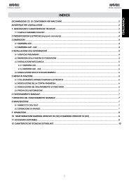
INDICE<br />
Guida per l’installatore<br />
1. DESCRIZIONE E CARATTERISTICHE TECNICHE pag.2<br />
2. PREDISPOSIZIONI ELETTRICHE pag.2<br />
3. INSTALLAZIONE DELL’AUTOMAZIONE pag.2<br />
3.1. VERIFICHE PRELIMINARI pag.2<br />
3.2. INSTALLAZIONE DELL’OPERATORE pag.2<br />
3.3. MONTAGGIO DELLA CREMAGLIERA pag.2<br />
3.4. POSIZIONAMENTO DEI MAGNETI DI FINECORSA pag.3<br />
4. COLLEGAMENTI ELETTRICI pag.3<br />
5. MESSA IN FUNZIONE pag.3<br />
6. PROVA DELL’AUTOMAZIONE pag.3<br />
7. FUNZIONAMENTO MANUALE pag.3<br />
8. APPLICAZIONI PARTICOLARI pag.3<br />
9. MANUTENZIONE pag.3<br />
10. RIPARAZIONE pag.3<br />
11. KIT BATTERIE (Optional) pag.3<br />
ITALIANO<br />
DICHIARAZIONE CE DI CONFORMITÁ PER MACCHINE<br />
(DIRETTIVA 98/37/CE)<br />
Fabbricante:<br />
Indirizzo:<br />
Dichiara che:<br />
GENIUS S.p.A.<br />
Via Padre Elzi, 32 - 24050 - Grassobbio- Bergamo - ITALIA<br />
L’operatore mod. <strong>MILORD</strong> <strong>424</strong> <strong>ENV</strong> - <strong>MILORD</strong> <strong>824</strong> <strong>ENV</strong><br />
• è costruito per essere incorporato in una macchina o per essere assemblato con altri macchinari per costituire una macchina ai<br />
sensi della Direttiva 98/37/CE;<br />
• è conforme ai requisiti essenziali di sicurezza delle seguenti altre direttive CEE:<br />
• 2006/95/CE direttiva Bassa Tensione.<br />
• 2004/108/CE direttiva Compatibilità elettromagnetica.<br />
• Inoltre dichiara che non è consentito mettere in servizio il macchinario fino a che la macchina in cui sarà incorporato o di cui diverrà<br />
componente sia stata identificata e ne sia stata dichiarata la conformità alle condizioni della Direttiva 89/392/CEE e successive<br />
modifiche trasposta nella legislazione nazionale dal DPR n°459 del 24 Luglio 1996.<br />
Grassobbio, 15 Settembre 2009<br />
L’Amministratore Delegato<br />
D. Gianantoni<br />
Note per la lettura dell’istruzione<br />
Leggere completamente questo manuale di installazione prima di iniziare l’installazione del prodotto.<br />
Il simbolo evidenzia note importanti per la sicurezza delle persone e l’integrità dell’automazione.<br />
Il simbolo richiama l’attenzione su note riguardanti le caratteristiche od il funzionamento del prodotto.
Pagina <br />
<strong>MILORD</strong> <strong>424</strong> <strong>ENV</strong> - <strong>MILORD</strong> <strong>824</strong> <strong>ENV</strong><br />
Guida per l’installatore<br />
ITALIANO<br />
Vi ringraziamo per aver scelto un nostro prodotto. GENIUS è certa<br />
che da esso otterrete tutte le prestazioni necessarie al Vostro<br />
impiego. Tutti i nostri prodotti sono frutto di una pluriennale esperienza<br />
nel campo degli automatismi, rafforzata dal fatto di essere<br />
parte del gruppo leader mondiale del settore.<br />
Nel centro del manuale è stato realizzato un opuscolo<br />
staccabile con tutte le immagini per l’installazione.<br />
L’automazione <strong>MILORD</strong> <strong>ENV</strong> per cancelli scorrevoli residenziali<br />
è un operatore elettromeccanico che trasmette il movimento<br />
all’anta tramite un pignone accoppiato opportunamente ad<br />
una cremagliera fissata sul cancello.<br />
Il sistema irreversibile garantisce il blocco meccanico quando il<br />
motore non è in funzione e quindi non occorre installare alcuna<br />
serratura. Un comodo sblocco rende manovrabile il cancello in<br />
caso di black-out o disservizio.<br />
Grazie al continuo controllo del motore da parte della centrale<br />
di comando (encoder virtuale) l’automazione è in grado controllare<br />
costantemente la posizione del cancello, arrestandone il<br />
movimento nel caso si riscontrino ostacoli.<br />
Tutte le caratteristiche ed i comportamenti specificati nel<br />
presente manuale si riferiscono ad installazioni omogenee,<br />
tutte le componenti dell’automazione di produzione<br />
GENIUS.<br />
1. DESCRIZIONE E CARATTERISTICHE TECNICHE<br />
Con riferimento alla figura 1:<br />
Pos<br />
a<br />
b<br />
c<br />
d<br />
e<br />
f<br />
g<br />
h<br />
i<br />
Motoriduttore<br />
Carter di copertura<br />
Centrale di comando<br />
Pignone<br />
Piastra di fondazione<br />
Sensore magnetico<br />
Comando di sblocco<br />
Kit batterie (Optional)<br />
Carter copertura motore<br />
Caratteristiche tecniche operatori<br />
Alimentazione<br />
Modello<br />
Alimentazione motore<br />
Descrizione<br />
Milord <strong>424</strong><br />
<strong>ENV</strong><br />
Milord <strong>824</strong><br />
<strong>ENV</strong><br />
230/115 V~ 50/60Hz<br />
24 Vdc<br />
Potenza assorbita 60 W 80 W<br />
Pignone<br />
Z16 M4<br />
Coppia max. 13.5 Nm 24 Nm<br />
Coppia nominale 9 Nm 16 Nm<br />
Spinta max. 40 daN 65 daN<br />
Cicli consecutivi<br />
Frequenza d’utilizzo a 20°C<br />
30 cicli a<br />
Residenziale<br />
Cicli giornalieri consigliati 80 cicli 150 cicli<br />
Temperatura ambiente<br />
-20°C +55°C<br />
Peso operatore 10.5 Kg 11 Kg<br />
Grado di protezione<br />
IP44<br />
Peso max. cancello 400 Kg 800 Kg<br />
Velocità cancello<br />
Lunghezza max.cancello<br />
Dimensioni operatore<br />
12 m/min<br />
10 m<br />
240 x 290 x 270 mm<br />
a<br />
Il numero di cicli consecutivi è calcolato su cancelli di lunghezza<br />
massima pari a 5 metri.<br />
Tutte le caratteristiche tecniche riportate in tabella sono<br />
garantite solo abbinando al motoriduttore l’elettronica di<br />
comando GENIUS.<br />
Con riferimento alla figura 2:<br />
2. PREDISPOSIZIONI ELETTRICHE<br />
Pos Descrizione N°/sez. cavi<br />
a Alimentazione elettrica 3x1.5 mm 2<br />
b Fotocellula TX 2x0.5 mm 2<br />
c Fotocellula RX 4x0.5 mm 2<br />
d Selettore a chiave 3 / 2x0.5 mm 2<br />
e Lampeggiante 2x1.5 mm 2<br />
f Antenna esterna Cavo coassiale in dotazione<br />
Per la messa in opera dei cavi elettrici utilizzare adeguati<br />
tubi rigidi e/o flessibili.<br />
Separare sempre i cavi di collegamento degli accessori a<br />
bassa tensione da quelli di alimentazione 230/115V~. Per<br />
evitare qualsiasi interferenza utilizzare guaine separate<br />
3. INSTALLAZIONE DELL’AUTOMAZIONE<br />
3.1. VERIFICHE PRELIMINARI<br />
Per un corretto funzionamento dell’automazione la struttura del<br />
cancello esistente, o da realizzare, deve presentare i seguenti<br />
requisiti:<br />
• Il peso e le dimensioni del cancello deve corrispondere a quanto<br />
indicato nella tabella delle caratteristiche tecniche;<br />
• Verificare che vi sia un efficace presa di terra per il collegamento<br />
dell’operatore;<br />
• Gli elementi costruttivi meccanici devono essere in accordo con<br />
quanto stabilito dalla Norme EN12604 e EN12605;<br />
• Superficie dell’anta liscia (priva di sporgenze);<br />
• Movimento regolare ed uniforme dell’anta, privo di attriti durante<br />
tutta la corsa;<br />
• Assenza di oscillazioni laterali dell’anta;<br />
• Ottimo stato dei sistemi di scorrimento inferiore e superiore.<br />
L’utilizzo di una guida a terra a gola arrotondata è preferibile<br />
per ottenere degli attriti di scorrimento ridotti.<br />
• Presenza di solo due ruote di scorrimento<br />
• Presenza degli arresti meccanici di sicurezza per evitare pericoli<br />
di deragliamento del cancello; tali arresti devono essere fissati<br />
saldamente al suolo o sulla guida a terra circa 40 mm oltre la<br />
posizione di finecorsa.<br />
• Assenza di serrature meccaniche di chiusura.<br />
1.<br />
2.<br />
3.<br />
4.<br />
5.<br />
6.<br />
7.<br />
8.<br />
9.<br />
Si raccomanda di effettuare gli eventuali interventi fabbrili<br />
prima d’installare l’automazione.<br />
Lo stato della struttura influenza direttamente l’affidabilità e<br />
la sicurezza dell’automazione.<br />
3.2. INSTALLAZIONE DELL’OPERATORE<br />
Assemblare la piastra di fondazione come da Fig. 3.<br />
Eseguire uno scavo per la piastra di fondazione come da fig.<br />
4. La piastra di fondazione deve essere posizionata come da<br />
fig. 5 (chiusura destra) o fig. 6 (chiusura sinistra) per garantire<br />
il corretto ingranamento tra il pignone e la cremagliera.<br />
Mettere in opera i tubi flessibili necessari per il passaggio<br />
dei cavi di collegamento tra il motoriduttore, gli accessori e<br />
l’alimentazione elettrica. I tubi flessibili devono uscire circa 3<br />
cm dal foro presente sulla piastra.<br />
Murare perfettamente in piano la piastra.<br />
Attendere che il cemento abbia fatto presa nello scavo.<br />
Predisporre i cavi elettrici per il collegamento con gli accessori<br />
e l’alimentazione elettrica (paragrafo 2). Per effettuare<br />
agevolmente i collegamenti elettrici sull’apparecchiatura<br />
elettronica fare fuoriuscire i cavi elettrici di circa 20 cm dal<br />
foro della piastra di fondazione.<br />
Fissare l’operatore sulla piastra di fondazione utilizzando le<br />
viti e rondelle in dotazione come da fig. 7. Il posizionamento<br />
dell’operatore è indicato nella fig. 8. Durante tale operazione<br />
fare passare i cavi elettrici attraverso l’apposito foro presente<br />
sulla base del corpo del motoriduttore.<br />
Fare passare i cavi elettrici di collegamento attraverso l’apposito<br />
foro presente sulla base del supporto dell’apparecchiatura<br />
utilizzando il passacavo in dotazione.<br />
Eseguire i collegamenti elettrici all’apparecchiatura elettroni-
<strong>MILORD</strong> <strong>424</strong> <strong>ENV</strong> - <strong>MILORD</strong> <strong>824</strong> <strong>ENV</strong><br />
Pagina <br />
Guida per l’installatore<br />
1.<br />
2.<br />
3.<br />
4.<br />
5.<br />
6.<br />
7.<br />
ca di comando come da istruzioni dell’apparecchiatura<br />
1) Collegare il cavo di terra dell’impianto.<br />
2) L’operatore viene fornito per un’installazione che prevede,<br />
vista dall’interno, la chiusura del cancello a destra<br />
dell’operatore (fig. 5). Nel caso di chiusura a sinistra è<br />
necessario invertire i fili d’alimentazione del motore, vedi<br />
istruzioni apparecchiatura elettronica.<br />
3.3. MONTAGGIO DELLA CREMAGLIERA<br />
Predisporre la cremagliera (fornibile a richiesta), con le viti TE<br />
M8 x 25 e i distanziali a saldare in dotazione, come da Fig. 9.<br />
Per evitare di saldare sul cancello sono disponibili dei distanziali<br />
passanti zincati con viti di fissaggio TE M8 x 50.<br />
È consigliabile serrare le viti di fissaggio della cremagliera<br />
nella parte superiore dell’asola. Tale posizione consente<br />
di alzare la cremagliera quando nel tempo, il cancello<br />
tenderà ad abbassarsi.<br />
Sbloccare l’operatore (vedi paragrafo 7).<br />
Portare manualmente l’anta in posizione d’apertura.<br />
Appoggiare sul pignone il primo elemento di cremagliera in<br />
corrispondenza del primo distanziale (fig. 10).<br />
Fissare l’elemento di cremagliera all’anta con un morsetto<br />
(fig. 10).<br />
Fare scorrere manualmente l’anta verso la chiusura fino ad<br />
arrivare in corrispondenza del terzo distanziale della cremagliera,<br />
e fissarlo con un punto di saldatura.<br />
Saldare definitivamente i tre distanziali sul cancello. Per fissare<br />
correttamente gli altri elementi di cremagliera necessari per<br />
arrivare in posizione di chiusura agire come segue:<br />
a–<br />
b–<br />
Accostare un altro elemento di cremagliera all’ultimo fissato<br />
utilizzando un pezzo di cremagliera per mettere in fase la<br />
dentatura dei due elementi (fig. 11).<br />
Fare scorrere manualmente l’anta verso la chiusura fino ad<br />
arrivare in corrispondenza del pignone con il terzo distanziale<br />
dell’elemento da fissare (fig. 11).<br />
Verificare che, guardando il motore dall’alto, tutti gli elementi<br />
di cremagliera lavorino sul centro dei denti del pignone.<br />
In caso contrario adattare la posizione del motoriduttore.<br />
c– Saldare i tre distanziali dell’elemento (fig. 11).<br />
d–<br />
e–<br />
a) Non saldare assolutamente gli elementi di cremagliera<br />
nè ai distanziali, nè tra di loro.<br />
b) Non utilizzare assolutamente grasso o altri prodotti lubrificanti<br />
tra pignone e cremagliera.<br />
Per ottenere il corretto gioco tra il pignone e la cremagliera<br />
abbassare il motoriduttore di 1,5 mm agendo sui dadi di<br />
supporto della piastra di fondazione. Al termine di tale<br />
regolazione serrare opportunamente i dadi di fissaggio<br />
dell’operatore.<br />
Nel caso di cancello di nuova costruzione verificare tale<br />
gioco (fig.12) dopo alcuni mesi dall’installazione.<br />
Verificare manualmente che il cancello sia libero di aprirsi<br />
completamente e che il movimento dell’anta sia regolare<br />
e privo di attriti.<br />
3.4. POSIZIONAMENTO DEI MAGNETI DI FINECORSA<br />
L’operatore è dotato di un finecorsa magnetico, che comanda<br />
l’arresto del moto del cancello nel momento in cui il magnete,<br />
fissato nella parte superiore della cremagliera, attiva il sensore. I<br />
magneti forniti con l’operatore sono appositamente polarizzati<br />
ed azionano solo un contatto del sensore, il contatto di chiusura<br />
o quello di apertura. Il magnete che aziona il contatto di cancello<br />
aperto riporta raffigurato un lucchetto aperto, viceversa il magnete<br />
che attiva il contatto di cancello chiuso riporta il simbolo<br />
di lucchetto chiuso.<br />
Per il corretto funzionamento della centrale il magnete con il<br />
lucchetto aperto deve essere posizionato in prossimità del bordo<br />
d’apertura del cancello, viceversa il magnete che raffigura il<br />
lucchetto chiuso si deve trovare in corrispondenza del bordo di<br />
chiusura del cancello, vedi figure 13 e 14.<br />
Per posizionare correttamente i due magneti di finecorsa agire<br />
come di seguito:<br />
1. Assemblare i due magneti come indicato in figura 13.<br />
2.<br />
3.<br />
4.<br />
5.<br />
6.<br />
7.<br />
8.<br />
Predisporre l’operatore per il funzionamento manuale, vedi<br />
paragrafo 7, ed alimentare il sistema.<br />
Portare manualmente il cancello in posizione d’apertura<br />
lasciando circa 40 mm dall’arresto meccanico di apertura.<br />
Far scorrere sulla cremagliera il magnete con il lucchetto<br />
aperto nella direzione di apertura, vedi figura 15. Appena<br />
il led relativo al finecorsa di apertura presente sulla scheda<br />
si spegne far avanzare il magnete di altri 10 mm e fissarlo<br />
provvisoriamente con le apposite viti.<br />
Ripetere le operazioni dal punto 3 per il magnete di chiusura.<br />
Ribloccare il sistema (vedi paragrafo7).<br />
Prima di inviare un’impulso assicurarsi che il cancello non si<br />
possa muovere manualmente.<br />
Comandare un ciclo completo per verificare il corretto funzionamento<br />
dei finecorsa.<br />
- Per evitare danneggiamenti dell’operatore e/o interruzioni<br />
del funzionamento dell’automazione è necessario lasciare<br />
circa 40 mm dagli arresti meccanici di sicurezza.<br />
- Controllare che a fine manovra, sia di apertura che di chiusura,<br />
il rispettivo contatto rimanga attivato (led spento).<br />
Apportare le opportune modifiche alla posizione dei magneti<br />
e fissarli definitivamente.<br />
4. COLLEGAMENTI ELETTRICI<br />
Collegare il cavo di massa a terra della linea di alimentazione alla<br />
vite di fissaggio del supporto scheda, come indicato in fig. 16.<br />
1.<br />
2.<br />
3.<br />
5. MESSA IN FUNZIONE<br />
Programmare l’apparecchiatura elettronica secondo le<br />
proprie esigenze come da istruzioni relative.<br />
Alimentare il sistema e verificare lo stato dei leds come<br />
dalla tabella riportata nelle istruzioni dell’apparecchiatura<br />
elettronica.<br />
Dopo aver eseguito la prova dell’automazione (paragrafo.<br />
6), fissare il carter di protezione sull’operatore utilizzando le<br />
viti in dotazione come da fig. 17.<br />
6. PROVA DELL’AUTOMAZIONE<br />
Procedere alla verifica funzionale dell’automazione e di tutti gli<br />
accessori ad essa collegati.<br />
Consegnare al Cliente la pagina “Guida per l’Utente” e illustrare<br />
il corretto funzionamento e utilizzo dell’automazione.<br />
7. FUNZIONAMENTO MANUALE<br />
Nel caso sia necessario azionare manualmente il cancello a<br />
causa di mancanza di corrente o disservizio dell’automazione, è<br />
necessario agire sul dispositivo di sblocco come segue:<br />
• Togliere alimentazione al sistema.<br />
• Utilizzando una moneta ruotare in senso orario la serratura sino<br />
al suo arresto (Fig. 18 rif. a).<br />
• Tirare la leva come indicato in fig. 18 rif. b.<br />
• Muovere manualmente il cancello.<br />
Per ripristinare il normale funzionamento agire come di seguito:<br />
• Togliere alimentazione al sistema.<br />
• Posizionare il cancello circa a metà della corsa di apertura<br />
• Riportare in posizione la leva di sblocco;<br />
• Utilizzando una moneta ruotare in senso antiorario la serratura<br />
sino al suo arresto;<br />
• Dare alimentazione al sistema.<br />
Al ripristino della tensione di alimentazione comandare un<br />
ciclo di apertura completo.<br />
Prima di inviare un’impulso assicurarsi che il cancello non si<br />
possa muovere manualmente.<br />
8. APPLICAZIONI PARTICOLARI<br />
Sono ESPRESSAMENTE VIETATE applicazioni diverse da quelle descritte<br />
nel presente manuale<br />
ITALIANO
Pagina <br />
<strong>MILORD</strong> <strong>424</strong> <strong>ENV</strong> - <strong>MILORD</strong> <strong>824</strong> <strong>ENV</strong><br />
Guida per l’installatore<br />
ITALIANO<br />
9. MANUTENZIONE<br />
Al fine d’assicurare nel tempo un corretto funzionamento ed un<br />
costante livello di sicurezza è opportuno eseguire, con cadenza<br />
semestrale, un controllo generale dell’impianto. Nel fascicolo<br />
“Guida per l’utente” è stato predisposto un modulo per la registrazione<br />
degli interventi.<br />
10. RIPARAZIONE<br />
L’utente utilizzatore deve astenersi da qualsiasi tentativo di riparazione<br />
o d’intervento e deve rivolgersi solo ed esclusivamente a<br />
personale qualificato GENIUS o centri d’assistenza GENIUS.<br />
11. KIT BATTERIE (Optional)<br />
Il kit batterie tampone permette di sopperire ad eventuali mancanze<br />
dell’alimentazione elettrica.<br />
Per il posizionamento del kit batterie a bordo del motoriduttore<br />
fare riferimento alle seguenti istruzioni:<br />
1.<br />
2.<br />
Rimuovere il carter di copertura del motore, Fig. 19 rif. a.<br />
Posizionare il kit batterie nellapposito alloggiamento, Fig. 19<br />
rif. b.<br />
Riposizionare il carter di copertura del motore, Fig. 19 rif. c.<br />
3.<br />
Per il collegamento del kit batterie fare riferimento alle istruzioni<br />
della centrale di comando.<br />
Le batterie entrano in funzione quando viene a mancare la<br />
tensione di rete. Il funzionamento dell’automazione con<br />
il kit batterie è da considerarsi come una situazione di<br />
emergenza.<br />
Il numero di cicli eseguibili con l’automazione alimentata<br />
tramite le batterie è influenzato direttamente dallo stato<br />
delle batterie, dal tempo trascorso dalla mancanza dell’alimentazione<br />
di rete, dalla struttura del cancello ecc..
<strong>MILORD</strong> <strong>424</strong> <strong>ENV</strong> - <strong>MILORD</strong> <strong>824</strong> <strong>ENV</strong><br />
Pagina <br />
Guida per l’installatore<br />
ITALIANO
Page <br />
<strong>MILORD</strong> <strong>424</strong> <strong>ENV</strong> - <strong>MILORD</strong> <strong>824</strong> <strong>ENV</strong><br />
Guide for the installer<br />
INDEX<br />
ENGLISH<br />
1. DESCRIPTION AND TECHNICAL SPECIFICATIONS page.7<br />
2. ELECTRICAL SET-UP page.7<br />
3. INSTALLING THE AUTOMATED SYSTEM page.7<br />
3.1. PRELIMINARY CHECKS page.7<br />
3.2. INSTALLING THE OPERATOR page.7<br />
3.3. INSTALLING THE RACK page.7<br />
3.4. POSITIONING THE STROKE-LIMIT MAGNETS page.8<br />
4. ELECTRICAL CONNECTIONS page.8<br />
5. START-UP page.8<br />
6. AUTOMATED SYSTEM TEST page.8<br />
7. MANUAL MODE OPERATION page.8<br />
8. SPECIAL APPLICATIONS page.8<br />
9. MAINTENANCE page.8<br />
10. REPAIRS page.8<br />
11. BATTERY KIT (Optional) page.8<br />
CE DECLARATION OF CONFORMITY FOR MACHINES<br />
(DIRECTIVE 98/37/EC)<br />
Manufacturer:<br />
Address:<br />
Declares that:<br />
GENIUS S.p.A.<br />
Via Padre Elzi, 32 - 24050 - Grassobbio- Bergamo - ITALY<br />
Operator mod. <strong>MILORD</strong> <strong>424</strong> <strong>ENV</strong> - <strong>MILORD</strong> <strong>824</strong> <strong>ENV</strong><br />
• is built to be integrated into a machine or to be assembled with other machinery to create a machine under the provisions of<br />
Directive 98/37/EC;<br />
• conforms to the essential safety requirements of the following EEC directives:<br />
• 2006/95/EC Low Voltage directive.<br />
• 2004/108/EC Electromagnetic Compatibility directive.<br />
• and also declares that it is prohibited to put into service the machinery until the machine in which it will be integrated or of which it<br />
will become a component has been identified and declared as conforming to the conditions of Directive 89/392/EEC and subsequent<br />
modifications assimilated in Italian National legislation under Presidential decree No.459 of 24 July 1996.<br />
Grassobbio, September 15, 2009<br />
Managing Director<br />
D. Gianantoni<br />
The symbol<br />
Notes on reading the instruction<br />
Read this installation manual to the full before you begin installing the product.<br />
indicates notes that are important for the safety of persons and for the good condition of the automated system.<br />
The symbol draws your attention to the notes on the characteristics and operation of the product.
<strong>MILORD</strong> <strong>424</strong> <strong>ENV</strong> - <strong>MILORD</strong> <strong>824</strong> <strong>ENV</strong><br />
Page <br />
Guide for the installer<br />
Thank you for choosing our product. GENIUS is sure that it will give<br />
you all the performances you are looking for. All our products<br />
are the result of a long experience in the field of the automated<br />
systems, reinforced by the fact of being part of the world leading<br />
group of this sector.<br />
In the middle of the handbook you will find a detachable<br />
brochure with the images for the installation.<br />
The <strong>MILORD</strong> <strong>ENV</strong> automated system for residential sliding gates<br />
is an electro-mechanical operator which transmits motion to the<br />
leaf through a pinion gear suitably coupled to a rack fitted on<br />
the gate.<br />
The non-reversing system ensures mechanical locking when the<br />
motor is not operating and, therefore, installing a lock is unnecessary.<br />
A handy release facility makes it possible to move the gate<br />
in the event of a power cut or fault.<br />
Thanks to the on-going motor check performed by the control<br />
unit (virtual encoder), the automated system is able to check the<br />
gate position continuously and to stop its movement in the event<br />
of obstacles detection.<br />
All characteristics and behaviours indicated in this manual<br />
refer to homogeneous installations, every component of<br />
the automated system is produced by GENIUS.<br />
1. DESCRIPTION AND TECHNICAL SPECIFICATIONS<br />
With reference to Figure 1<br />
Pos<br />
a<br />
b<br />
c<br />
d<br />
e<br />
f<br />
g<br />
h<br />
i<br />
Gearmotor<br />
Protective housing<br />
Control unit<br />
Pinion<br />
Foundation plate<br />
Magnetic sensor<br />
Release device<br />
Battery Kit (Optional)<br />
Motor housing<br />
Description<br />
Technical specifications of operators<br />
Power supply<br />
Model<br />
Motor Power supply<br />
Mlord <strong>424</strong><br />
<strong>ENV</strong><br />
Milord <strong>824</strong><br />
<strong>ENV</strong><br />
230/115 V~ 50/60Hz<br />
24 Vdc<br />
Absorbed power 60 W 80 W<br />
Pinion<br />
Z16 M4<br />
Max torque 13.5 Nm 24 Nm<br />
Nominal torque 9 Nm 16 Nm<br />
Max thrust 40 daN 65 daN<br />
Consecutive cycles<br />
Use frequency a 20°C<br />
30 cycles a<br />
Residential use<br />
Recommended daily cycles 80 cycles 150 cycles<br />
Operating ambient temperature<br />
-20°C +55°C<br />
Operator weight 10.5 Kg 11 Kg<br />
Protection class<br />
IP44<br />
Max gate weight 400 Kg 800 Kg<br />
Gate speed<br />
Max gate length<br />
Dimensions<br />
12 m/min<br />
10 m<br />
240 x 290 x 270 mm<br />
a<br />
Consecutive number of cycles on gates with max. length of 5<br />
metres.<br />
All technical specifications indicated in the table are only<br />
guaranteed if GENIUS control board is coupled to the<br />
gearmotor.<br />
With reference to Figure 2<br />
2. ELECTRICAL SET-UP<br />
Pos Description N°/sectn. of cables<br />
a Operator 3x1.5 mm 2<br />
b Photocells TX 2x0.5 mm 2<br />
c Photocells RX 4x0.5 mm 2<br />
d Key push-button 3 / 2x0.5 mm 2<br />
e Flashing lamp 2x1.5 mm 2<br />
f<br />
External antenna<br />
Coaxial cable supplied as<br />
standard<br />
To lay cables, use adequate rigid and/or flexible tubes.<br />
Always separate connection cables of low voltage accessories<br />
from those operating at 230/115V~. To prevent any<br />
interference whatever, use separate sheaths.<br />
3. INSTALLING THE AUTOMATED SYSTEM<br />
3.1. PRELIMINARY CHECKS<br />
To ensure a correctly operating automated system, the structure<br />
of the existing gate or gate to be built must satisfy the following<br />
requirements:<br />
• The weight and dimensions of the gate must comply with the<br />
indications given in the table of the technical specifications;<br />
• Check if an efficient earth socket is available for connecting<br />
the operator;<br />
• The mechanical construction elements must comply with the<br />
provisions of the EN12604 and EN12605 Standards;<br />
• Smooth leaf surface (without any projections);<br />
• Smooth, uniform gate movement, without any friction during<br />
the entire travel;<br />
• No sideward leaf swings;<br />
• Top and bottom sliding systems must be in excellent condition.<br />
It is preferable to use a ground-level guide with rounded groove<br />
to obtain reduced sliding friction.<br />
• Only two sliding wheels are present<br />
• Mechanical safety stops required to prevent the danger of gate<br />
derailment; these stops must be firmly secured to the ground or<br />
to the ground-level guide at about 40 mm beyond the travel<br />
limit position.<br />
• No mechanical closing locks.<br />
1.<br />
2.<br />
3.<br />
4.<br />
5.<br />
6.<br />
7.<br />
8.<br />
9.<br />
We advise you to carry out the metalwork jobs before<br />
installing the automated system.<br />
The condition of the structure directly influences the reliability<br />
and safety of the automated system.<br />
3.2. INSTALLING THE OPERATOR<br />
Assemble the foundation plate as in Fig.3.<br />
Dig a cavity for the foundation plate as shown in Fig. 4. The<br />
foundation plate must be located as shown in Fig. 5 (right<br />
closing) or Fig.6 (left closing) to ensure correct meshing<br />
between rack and pinion.<br />
Lay the flexible pipes for routing the connection cables<br />
between gearmotor, accessories and electrical power supply.<br />
The flexible pipes must protrude by about 3 cm from the<br />
hole on the plate.<br />
Wall in the plate perfectly levelled.<br />
Wait for the cement to set in the cavity.<br />
Lay the electrical cables for connection to the accessories<br />
and the electrical power supply (paragraph 2). To facilitate<br />
making the electrical connections on the control unit, make<br />
the electric cables protrude by about 20 cm from the hole<br />
on the foundation plate.<br />
Secure the operator on the foundation plate, using the supplied<br />
screws and washers as shown in Fig. 7. The operator’s<br />
position is shown in Fig. 8. When positioning the operator,<br />
route the electrical cables through the hole on the base of<br />
the gearmotor body.<br />
Route the connecting electrical cables through the hole<br />
on the base of the unit’s support, using the supplied cable<br />
gripper.<br />
Make the electrical connections to the electronic control unit<br />
ENGLISH
Page <br />
<strong>MILORD</strong> <strong>424</strong> <strong>ENV</strong> - <strong>MILORD</strong> <strong>824</strong> <strong>ENV</strong><br />
Guide for the installer<br />
ENGLISH<br />
1.<br />
2.<br />
3.<br />
4.<br />
5.<br />
6.<br />
7.<br />
according to the instructions for the unit.<br />
1) Connect the earth cable of the system.<br />
2) The operator is supplied for installation with the gate<br />
closing on the right of the operator (looking from the inside)<br />
(fig. 5). In the event of a left-closing gate, you need<br />
to reverse the power wires of the motor, see control board<br />
instructions.<br />
3.3. INSTALLING THE RACK<br />
Prepare the rack (supplied on request), with the supplied Hexhead<br />
M8 x 25 screws, and spacers to be welded, as shown<br />
in Fig. 9. To avoid having to weld on the gate, galvanised<br />
through-spacers and Hex-head M8 x 50 securing screws are<br />
available.<br />
We advise you to tighten the securing screws of the rack on<br />
the top end of the slot. This position will enable you to raise<br />
the rack when the gate tends to lower through time.<br />
Release the operator (see paragraph 7).<br />
Manually move the leaf to its open position.<br />
Lay the first element of the rack on the pinion, on the first<br />
spacer (fig. 10).<br />
Secure the rack element to the leaf with a clamp (fig. 10).<br />
Manually slide the leaf toward the closing point until you<br />
reach the rack’s third spacer, and fix it with a weld spot.<br />
Definitively weld the three spacers on the gate. Procedure<br />
for correctly fixing the other rack elements required to reach<br />
the closing position:<br />
a–<br />
b–<br />
Bring near another rack element to the last fixed element,<br />
using a piece of rack to synchronise the teeth with the two<br />
elements (fig. 11).<br />
Manually slide the leaf toward the closing point until you<br />
reach the pinion with the third spacer of the element to<br />
be secured (fig. 11).<br />
Looking at the motor from above, check if all elements of the<br />
rack are working in the centre of the pinion teeth. If this is<br />
not the case, you need to adapt the gearmotor position.<br />
c– Weld the element’s three spacers (fig. 10).<br />
d–<br />
e–<br />
a) Do not, on any account, weld the rack elements either to<br />
the spacers or to each other.<br />
b) Do not, on any account, use grease or other lubricants<br />
between rack and pinion.<br />
To obtain correct play between rack and pinion, lower the<br />
gearmotor by 1.5 mm, using the nuts supporting the foundation<br />
plate. When you have finished adjusting, correctly<br />
tighten the operator securing nuts.<br />
If the gate was recently built, check this play (fig.12) a few<br />
months after installation.<br />
Manually check if the gate is free to open completely and if<br />
leaf movement is good and friction- free<br />
3.4. POSITIONING THE STROKE-LIMIT MAGNETS<br />
The operator has a magnetic limit-switch, which commands gate<br />
motion to stop when the magnet, which is secured to the upper<br />
part of the rack, activates the sensor. The magnets supplied with<br />
the operator are specifically polarised and activate only one of<br />
the sensor’s contacts: the closing or opening contact. The magnet<br />
activating the open gate contact bears an open padlock<br />
symbol, and, vice versa, the magnet activating the closed gate<br />
contact bears the closed padlock symbol.<br />
For the correct operation of the control unit, the magnet with<br />
open padlock must be positioned near the gate opening edge,<br />
vice versa the magnet with closed padlock must be positioned<br />
near the gate closing edge, see figures 13 and 14.<br />
Procedure for a correct positioning of the two stroke-limit magnets:<br />
1.<br />
2.<br />
3.<br />
4.<br />
Assemble the two magnets as shown in figure 13 or 14.<br />
Set the operator to manual mode operation - see paragraph<br />
7 - and power up the system.<br />
Manually take the gate to opening position, leaving about<br />
40 mm from the opening mechanical stop.<br />
Allow the magnet, with the padlock open, to slide on the<br />
rack in opening direction - see figure 15. As soon as the LED<br />
5.<br />
6.<br />
7.<br />
8.<br />
on the board, referring to the opening limit-switch, goes OFF,<br />
take the magnet forward by another 10 mm and fasten it<br />
provisionally with the appropriate screws.<br />
Repeat the operations from point 3 for the closing magnet.<br />
Re-lock the system (see paragraph 7).<br />
Before sending a pulse, make sure that the gate cannot be<br />
moved manually.<br />
Command a complete gate cycle to check if the limitswitches<br />
are operating correctly<br />
- To avoid damaging the operator and/or interrupting operation<br />
of the automated system, leave a distance of about<br />
40 mm from the safety mechanical stops.<br />
- Make sure that at the end of both the opening and closing<br />
manoeuvre, the relevant contact stays active (LED OFF).<br />
Change the position of the magnets as necessary and secure<br />
them definitively.<br />
4. ELECTRICAL CONNECTIONS<br />
Connect the grounding cable of the power line to the screw<br />
securing the board support, as shown in fig. 16.<br />
1.<br />
2.<br />
3.<br />
5. START-UP<br />
Program the control unit according to your needs, as per<br />
relevant instructions.<br />
Power up the system and check the condition of the LEDs<br />
according to the table in the control unit instructions.<br />
When you have run the automated system test (par.6), secure<br />
the protective housing on the operator, using the supplied<br />
screws as shown in fig. 17.<br />
6. AUTOMATED SYSTEM TEST<br />
Check operating efficiency of the automated system and all<br />
accessories connected to it.<br />
Hand the customer the “User’s Guide” page and explain how<br />
the automated system operates correctly and how it should be<br />
used.<br />
7. MANUAL MODE OPERATION<br />
If the gate has to be moved manually due to a power cut or fault<br />
of the automated system, use the release device as follows:<br />
• Cut power to the system.<br />
• Using a coin, turn the lock clockwise until it stops (Fig. 18 ref.<br />
a).<br />
• Pull the lever as shown in fig. 18 ref. b.<br />
• Move the gate by hand.<br />
Procedure for restoring normal operation:<br />
• Cut power to the system.<br />
• Position the gate at about halfway of opening travel.<br />
• Take the release lever back into its position;<br />
• Using a coin, turn the lock anti-clockwise until it stops;<br />
• Restore power to the system.<br />
when power is restored, command another complete<br />
opening cycle.<br />
Before sending a pulse, make sure that the gate cannot be<br />
moved manually.<br />
8. SPECIAL APPLICATIONS<br />
Applications other than those in this manual are EXPRESSLY<br />
PROHIBITED.<br />
9. MAINTENANCE<br />
To ensure correct long-term operation and a constant level of safety,<br />
we advise you to generally check the system every 6 months.<br />
In the “User’s Guide” booklet, there is a form for recording jobs.<br />
10. REPAIRS<br />
The User must not in any way attempt to repair or to take direct<br />
action and must solely contact qualified GENIUS personnel or<br />
GENIUS service centres.
<strong>MILORD</strong> <strong>424</strong> <strong>ENV</strong> - <strong>MILORD</strong> <strong>824</strong> <strong>ENV</strong><br />
Page <br />
Guide for the installer<br />
11. BATTERY KIT (Optional)<br />
The buffer battery kit enables the operation in the event of a<br />
mains power cut.<br />
To position the battery kit on the gearmotor, please refer to the<br />
following instructions:<br />
1.<br />
2.<br />
Remove the motor housing, Fig. 19 ref. a.<br />
Place the battery kit in its seat, Fig. 19 ref. b<br />
Re-position the motor housing, Fig. 19 ref. c<br />
3.<br />
To connect the battery kit, please refer to the instructions of the<br />
control unit.<br />
The batteries starts operating whenever a mains power cut is<br />
detected. The operation of the battery powered automated<br />
system is to be considered as an emergency situation.<br />
The number of cycles possible with the automated system<br />
battery powered depends directly on the battery status,<br />
on the time elapsing since mains power was cut, on the<br />
gate structure, etc<br />
ENGLISH
Page 10<br />
<strong>MILORD</strong> <strong>424</strong> <strong>ENV</strong> - <strong>MILORD</strong> <strong>824</strong> <strong>ENV</strong><br />
Guide pour l’installateur<br />
INDEX<br />
1. DESCRIPTION ET CARACTÉRISTIQUES TECHNIQUES page.11<br />
2. DISPOSITIONS ÉLECTRIQUES page.11<br />
3. INSTALLATION DE L’AUTOMATISME page.11<br />
3.1. VÉRIFICATIONS PRÉLIMINAIRES page.11<br />
3.2. INSTALLATION DE L’OPÉRATEUR page.11<br />
3.3. MONTAGE DE LA CRÉMAILLÈRE page.12<br />
3.4. POSITIONNEMENT DES AIMANTS DE FIN DE COURSE page.12<br />
4. CONNEXIONS ÉLECTRIQUES page.12<br />
5. MISE EN FONCTION page.12<br />
6. ESSAI DE L’AUTOMATISME page.12<br />
7. FONCTIONNEMENT MANUEL page.12<br />
8. APPLICATIONS SPÉCIALES page.12<br />
9. ENTRETIEN page.12<br />
10. RÉPARATION page.13<br />
11. KIT BATTERIES (Option) page.13<br />
FRANÇAIS<br />
DÉCLARATION CE DE CONFORMITÉ POUR MACHINES<br />
(DIRECTIVE 98/37/CE)<br />
Fabricant:<br />
Adresse:<br />
Déclare que:<br />
GENIUS S.p.A.<br />
Via Padre Elzi, 32 - 24050 - Grassobbio- Bergamo - ITALIE<br />
L’opérateur mod. <strong>MILORD</strong> <strong>424</strong> <strong>ENV</strong> - <strong>MILORD</strong> <strong>824</strong> <strong>ENV</strong><br />
• est construit pour être incorporé dans une machine ou pour être assemblé à d’autres appareillages, afin de constituer une machine<br />
conforme aux termes de la Directive 98/37/CE;<br />
• est conforme aux exigences essentielles de sécurité des directives CEE suivantes:<br />
• 2006/95/CE directive Basse Tension.<br />
• 2004/108/CE directive Compatibilité Électromagnétique.<br />
• On déclare en outre que la mise en service de l’outillage est interdite tant que la machine à laquelle il sera incorporé ou dont il<br />
deviendra un composant n’a pas été identifiée et déclarée conforme aux conditions de la Directive 89/392/CEE et modifications<br />
successives transposée dans la législation nationale par le DPR n°459 du 24 juillet 1996..<br />
Grassobbio, Septembre 15, 2009<br />
L’Administrateur Délégué<br />
D. Gianantoni<br />
Remarques pour la lecture de l’instruction<br />
Lire ce manuel d’installation dans son ensemble avant de commencer l’installation du produit.<br />
Le symbole souligne des remarques importantes pour la sécurité des personnes et le parfait état de l’automatisme.<br />
Le symbole attire l’attention sur des remarques concernant les caractéristiques ou le fonctionnement du produit.
<strong>MILORD</strong> <strong>424</strong> <strong>ENV</strong> - <strong>MILORD</strong> <strong>824</strong> <strong>ENV</strong><br />
Page 11<br />
Guide pour l’installateur<br />
Nous vous remercions d’avoir choisi un de nos produits. GENIUS<br />
est certaine qu’il vous permettra d’obtenir toutes les performances<br />
nécessaires pour votre usage. Tous nos produits sont le fruit<br />
d’une longue expérience dans le domaine des automatismes,<br />
renforcée par le fait que la société appartient au groupe leader<br />
mondial du secteur.<br />
Au milieu du manuel, vous trouverez un dossier détachable<br />
contenant toutes les images pour l’installation.<br />
L’automatisme <strong>MILORD</strong> <strong>ENV</strong> pour portails coulissants domestiques<br />
est un opérateur électromécanique qui transmet le mouvement<br />
au vantail par l’intermédiaire d’un pignon opportunément accouplé<br />
à une crémaillère fixée au portail.<br />
Le système irréversible garantit le blocage mécanique quand le<br />
moteur n’est pas en fonction; il n’est donc pas nécessaire d’installer<br />
de serrure. Un dispositif pratique de déverrouillage permet<br />
de manœuvrer le portail en cas de coupure de courant ou de<br />
dysfonctionnement.<br />
Grâce au contrôle continu du moteur de la part de la centrale<br />
de commande (encodeur virtuel), l’automatisme est en mesure<br />
de contrôler constamment la position du portail, en en arrêtant<br />
le mouvement en cas d’obstacles.<br />
Toutes les caractéristiques et les comportements spécifiés<br />
dans le présent manuel se réfèrent à des installations homogènes,<br />
tous les composants de l’automatisme produit<br />
par GENIUS.<br />
1. DESCRIPTION ET CARACTÉRISTIQUES<br />
TECHNIQUES<br />
Se référant à la figure 1<br />
Pos<br />
a<br />
b<br />
c<br />
d<br />
e<br />
f<br />
g<br />
h<br />
i<br />
Motoréducteur<br />
Carter de protection<br />
Centrale de commande<br />
Pignon<br />
Plaque de fondation<br />
Capteur magnétique<br />
Dispositif de déverrouillage<br />
Kit batteries (Option)<br />
Description<br />
Carter de protection moteur<br />
Caractéristiques techniques des opérateurs<br />
Modèle<br />
Milord <strong>424</strong> Milord <strong>824</strong><br />
<strong>ENV</strong> <strong>ENV</strong><br />
Alimentation<br />
230/115 V~ 50/60Hz<br />
Alimentation moteur<br />
24 Vdc<br />
Puissance absorbée 60 W 80 W<br />
Pignon<br />
Z16 M4<br />
Couple maxi 13.5 Nm 24 Nm<br />
Couple nominale 9 Nm 16 Nm<br />
Poussée maxi 40 daN 65 daN<br />
Cycles consécutifs<br />
30 cycles a<br />
Fréquence d’utilisation à 20°C<br />
Domestique<br />
Cycles journaliers préconisés 80 cycles 150 cycles<br />
Température de fonctionnement<br />
-20°C +55°C<br />
Poids opérateur 10.5 Kg 11 Kg<br />
Degré de protection<br />
IP44<br />
Poids maxi portail 400 Kg 800 Kg<br />
Vitesse portail<br />
12 m/min<br />
Longueur maxi portail<br />
10 m<br />
Dimensions<br />
240 x 290 x 270 mm<br />
a<br />
Nombre de cycles consécutifs sur des portails d’une longueur<br />
maximum de 5 mètres.<br />
L’ensemble des caractéristiques figurant dans le tableau<br />
ne sont garanties qu’en présence de l’électronique de<br />
commande GENIUS sur le motoréducteur<br />
Se référant à la figure 2<br />
2. DISPOSITIONS ÉLECTRIQUES<br />
Pos Description N°/sect. câbles<br />
a Motoréducteur 3x1.5 mm 2<br />
b Photocellule TX 2x0.5 mm 2<br />
c Photocelluls RX 4x0.5 mm 2<br />
d Bouton-poussoir à clé 3 / 2x0.5 mm 2<br />
e Lampe clignotante 2x1.5 mm 2<br />
f Antenne externe Câble coaxial fourni<br />
Utiliser des tubes rigides et/ou flexibles pour la pose des<br />
câbles électriques.<br />
Toujours séparer les câbles de connexion des accessoires<br />
à basse tension des câbles d’alimentation à 230/115V~.<br />
Utiliser des gaines séparées pour éviter toute interférence<br />
3. INSTALLATION DE L’AUTOMATISME<br />
3.1. VÉRIFICATIONS PRÉLIMINAIRES<br />
Pour un fonctionnement correct de l’automatisme, la structure<br />
du portail existant, ou à réaliser, doit présenter les conditions<br />
requises suivantes:<br />
• Le poids et les dimensions du portail doivent correspondre aux<br />
indications du tableau des caractéristiques techniques;<br />
• Vérifier la présence d’une prise de terre efficace pour le raccordement<br />
de l’opérateur;<br />
• Les éléments mécaniques de construction doivent être conformes<br />
aux Normes EN12604 et EN12605;<br />
• La surface du vantail doit être lisse (sans pièces saillantes);<br />
• Le mouvement du vantail doit être régulier et uniforme, sans<br />
frottements durant toute la course;<br />
• Absence d’oscillations latérales du vantail;<br />
• Excellent état des systèmes de coulissement inférieur et supérieur.<br />
Il est préférable de poser au sol un rail de guidage à gorge arrondie<br />
pour obtenir des frottements de coulissement réduits.<br />
• Présence de deux roues de coulissement seulement;<br />
• Présence d’arrêts mécaniques de sécurité pour éviter tout danger<br />
de déraillement du portail; ces arrêts doivent être solidement<br />
fixés au sol ou sur le rail de guidage au sol environ 40 mm au-delà<br />
de la position de fin de course.<br />
• Absence de serrures mécaniques de fermeture.<br />
1.<br />
2.<br />
3.<br />
4.<br />
5.<br />
6.<br />
7.<br />
8.<br />
On recommande de réaliser les ouvrages de forge avant<br />
d’installer l’automatisme.<br />
L’état de la structure influence directement la fiabilité et la<br />
sécurité de l’automatisme.<br />
3.2. INSTALLATION DE L’OPÉRATEUR<br />
Assembler la plaque de fondation d’après la Fig.3.<br />
Réaliser un creusage pour la plaque de fondation d’après<br />
la fig. 4. Positionner la plaque de fondation d’après la fig.<br />
5 (fermeture à droite) ou la fig. 6 (fermeture à gauche)<br />
pour garantir un engrenage correct entre le pignon et la<br />
crémaillère.<br />
Poser les tuyaux flexibles nécessaires pour le passage des<br />
câbles de connexion entre le motoréducteur, les accessoires<br />
et l’alimentation électrique. Les tuyaux flexibles doivent sortir<br />
d’environ 3 cm par le trou de la plaque.<br />
Sceller la plaque parfaitement à plat.<br />
Attendre que le béton ait fait prise dans le creusage.<br />
Disposer les câbles électriques pour la connexion aux accessoires<br />
et l’alimentation électrique (paragraphe 2). Pour<br />
réaliser facilement les connexions électriques sur l’armoire<br />
électronique, faire sortir les câbles électriques d’environ 20<br />
cm par le trou de la plaque de fondation.<br />
Fixer l’opérateur sur la plaque de fondation avec les vis et<br />
les rondelles fournies d’après la fig. 7. Le positionnement de<br />
l’opérateur est illustré dans la fig. 8. Durant cette opération,<br />
faire passer les câbles électriques à travers le trou spécifique<br />
présent sur la base du corps du motoréducteur.<br />
Faire passer les câbles électriques de connexion à travers le<br />
trou de la base du support de l’armoire au moyen du serrecâble<br />
fourni.<br />
FRANÇAIS
Page 12<br />
<strong>MILORD</strong> <strong>424</strong> <strong>ENV</strong> - <strong>MILORD</strong> <strong>824</strong> <strong>ENV</strong><br />
Guide pour l’installateur<br />
FRANÇAIS<br />
9.<br />
1.<br />
2.<br />
3.<br />
4.<br />
5.<br />
6.<br />
7.<br />
Réaliser les connexions électriques à l’armoire électronique<br />
de manœuvre en suivant les instructions de l’armoire.<br />
1) Connecter le câble de terre de l’installation.<br />
2) L’opérateur est fourni pour une installation qui prévoit,<br />
vue de l’intérieur, la fermeture du portail à droite de l’opérateur<br />
(fig. 5). En cas de fermeture à gauche, inverser les fils<br />
d’alimentation du moteur et du capteur magnétique, voir<br />
les instructions de l’armoire électronique.<br />
3.3. MONTAGE DE LA CRÉMAILLÈRE<br />
Disposer la crémaillère (fournie sur demande), avec les vis TE<br />
M8 x 25 et les entretoises à souder fournies, d’après la fig.9.<br />
Pour éviter de souder sur le portail, on fournit des entretoises<br />
passantes galvanisées avec des vis de fixation TE M8 x 50.<br />
On conseille de serrer les vis de fixation de la crémaillère<br />
dans la partie supérieure de la rainure. Cette position permet<br />
de soulever la crémaillère si le portail s’abaisse avec<br />
le temps.<br />
Déverrouiller l’opérateur (voir paragraphe 7).<br />
Amener manuellement le vantail en position d’ouverture.<br />
Poser sur le pignon le premier élément de la crémaillère au<br />
niveau de la première entretoise (fig. 10).<br />
Fixer l’élément de la crémaillère au vantail avec un étau<br />
(fig. 10).<br />
Faire coulisser manuellement le vantail vers la fermeture jusqu’à<br />
ce qu’on atteigne le niveau de la troisième entretoise<br />
de la crémaillère, et la fixer par un point de soudure.<br />
Souder définitivement les trois entretoises sur le portail. Pour<br />
fixer correctement les autres éléments de la crémaillère nécessaires<br />
pour arriver en position de fermeture, agir comme<br />
suit:<br />
a–<br />
b–<br />
Placer un autre élément de la crémaillère à côté du dernier<br />
élément fixé en utilisant un morceau de crémaillère pour<br />
mettre en phase la denture des deux éléments (fig. 11).<br />
Faire coulisser manuellement le vantail vers la fermeture<br />
jusqu’au niveau du pignon avec la troisième entretoise de<br />
l’élément à fixer (fig. 11).<br />
Vérifier qu’en regardant le moteur d’en haut, tous les éléments<br />
de la crémaillère travaillent sur le centre des dents<br />
du pignon. Dans le cas contraire, adapter la position du<br />
motoréducteur.<br />
c– Souder les trois entretoises de l’élément (fig. 11).<br />
d–<br />
e–<br />
a) Ne jamais souder les éléments de la crémaillère ni aux<br />
entretoises, ni les uns aux autres.<br />
b) Ne jamais utiliser de graisse ou d’autres produits lubrifiants<br />
entre le pignon et la crémaillère.<br />
Pour obtenir un jeu correct entre le pignon et la crémaillère,<br />
abaisser le motoréducteur de 1,5 mm en agissant sur les<br />
écrous de support de la plaque de fondation. Au terme<br />
de ce réglage, serrer opportunément les écrous de fixation<br />
de l’opérateur.<br />
Si le portail est de construction récente, vérifier ce jeu (fig.12)<br />
quelques mois après l’installation.<br />
Vérifier manuellement que le portail est libre de s’ouvrir complètement<br />
et que le mouvement du vantail est régulier et<br />
sans frottements.<br />
3.4. POSITIONNEMENT DES AIMANTS DE FIN DE COURSE<br />
L’opérateur est muni d’un fin de course magnétique qui commande<br />
l’arrêt du mouvement du portail au moment où l’aimant, fixé<br />
dans la partie supérieure de la crémaillère, active le capteur. Les<br />
aimants fournis avec l’opérateur sont spécialement polarisés et<br />
actionnent uniquement un contact du capteur, le contact de<br />
fermeture ou le contact d’ouverture. Sur l’aimant qui actionne le<br />
contact de portail ouvert est reproduit un cadenas ouvert, vice<br />
versa sur l’aimant qui active le contact de portail fermé est reproduit<br />
le symbole d’un cadenas fermé. Pour un fonctionnement<br />
correct de la centrale, l’aimant avec le cadenas ouvert doit être<br />
positionné à proximité du bord d’ouverture du portail ; vice versa,<br />
l’aimant avec le cadenas fermé doit être positionné au niveau<br />
du bord de fermeture du portail ; voir figures 13 et 14.<br />
Pour positionner correctement les deux aimants de fin de course,<br />
agir comme suit:<br />
1. Assembler les deux aimants d’après la figure 13 ou 14.<br />
2. Disposer l’opérateur pour le fonctionnement manuel, voir<br />
paragraphe 7, et mettre le système sous tension.<br />
3. Amener manuellement le portail en position d’ouverture<br />
en laissant environ 40 mm à partir de l’arrêt mécanique<br />
d’ouverture.<br />
4. Faire coulisser sur la crémaillère l’aimant avec le cadenas<br />
ouvert dans la direction d’ouverture, voir figure 15. Dès que la<br />
LED relative au fin de course d’ouverture présent sur la platine<br />
s’éteint, faire avancer l’aimant de 10 mm supplémentaires<br />
et le fixer provisoirement avec les vis spécifiques.<br />
5. Répéter les opérations à partir du point 3 pour l’aimant de<br />
fermeture.<br />
6. Bloquer de nouveau le système (voir paragraphe 7).<br />
7.<br />
8.<br />
Avant d’envoyer une impulsion, s’assurer que le portail ne<br />
puisse pas être actionné manuellement.<br />
Commander un cycle complet pour vérifier le fonctionnement<br />
des fins de course.<br />
- Pour éviter d’endommager l’opérateur et/ou d’interrompre<br />
le fonctionnement de l’automatisme, laisser une distance<br />
d’environ 40 mm des arrêts mécaniques de sécurité.<br />
- Contrôler qu’en fin de manœuvre, d’ouverture ou de fermeture,<br />
le contact respectif reste activé (LED éteinte).<br />
Modifier de façon opportune la position des aimants et les<br />
fixer définitivement.<br />
4. CONNEXIONS ÉLECTRIQUES<br />
Connecter le câble de masse à la terre de la ligne d’alimentation<br />
à la vis de fixation du support de la carte, d’après les indications<br />
de la fig. 16.<br />
1.<br />
2.<br />
3.<br />
5. MISE EN FONCTION<br />
Programmer l’armoire électronique suivant les exigences<br />
propres en suivant les instructions correspondantes.<br />
Mettre le système sous tension et vérifier l’état des LEDs<br />
d’après le tableau figurant dans les instructions de l’armoire<br />
électronique.<br />
Après avoir testé l’automatisme (paragraphe 6), fixer le<br />
carter de protection sur l’opérateur avec les vis fournies<br />
d’après la fig.17.<br />
6. ESSAI DE L’AUTOMATISME<br />
Procéder au contrôle fonctionnel de l’automatisme et de tous<br />
les accessoires connectés.<br />
Remettre au Client la page “Instructions pour l’Utilisateur” et illustrer<br />
le fonctionnement ainsi que l’utilisation de l’automatisme.<br />
7. FONCTIONNEMENT MANUEL<br />
S’il est nécessaire d’actionner manuellement le portail en raison<br />
d’une coupure de courant ou d’un dysfonctionnement de l’automatisme,<br />
agir sur le dispositif de déverrouillage comme suit:<br />
• Mettre le système hors tension.<br />
• Avec une pièce de monnaie, tourner la serrure en sens horaire<br />
jusqu’à son arrêt (Fig. 18 réf. a).<br />
• Tirer le levier d’après la fig. 18 réf. b.<br />
• Actionner le portail manuellement.<br />
Pour rétablir le fonctionnement normal, agir comme suit:<br />
• Mettre le système hors tension.<br />
• Positionner le portail environ à la moitié de la course d’ouverture.<br />
• Remettre le levier de déverrouillage dans sa position d’origine;<br />
• Avec une pièce de monnaie, tourner la serrure en sens antihoraire<br />
jusqu’à son arrêt;<br />
• Mettre le système sous tension.<br />
Au retour du courant, commander un cycle d’ouverture<br />
complet.<br />
Avant d’envoyer une impulsion, s’assurer que le portail ne<br />
peut pas être actionné manuellement.
<strong>MILORD</strong> <strong>424</strong> <strong>ENV</strong> - <strong>MILORD</strong> <strong>824</strong> <strong>ENV</strong><br />
Page 13<br />
Guide pour l’installateur<br />
8. APPLICATIONS SPÉCIALES<br />
Toute application différente de celles qui sont décrites dans ce<br />
manuel, sont FORMELLEMENT INTERDITES.<br />
9. ENTRETIEN<br />
Pour assurer un fonctionnement correct et un niveau de sécurité<br />
constant, exécuter, tous les six mois, un contrôle général de l’installation.<br />
Avec les “Instructions pour l’utilisateur”, on fournit un<br />
formulaire pour l’enregistrement des interventions.<br />
10. RÉPARATION<br />
L’utilisateur doit s’abstenir de toute tentative de réparation ou<br />
d’intervention et doit s’adresser uniquement et exclusivement au<br />
personnel qualifié GENIUS ou aux centres d’assistance GENIUS.<br />
11. KIT BATTERIES (Option)<br />
Le kit des batteries tampon permet de remédier aux éventuelles<br />
coupures de courant.<br />
Pour le positionnement correct du kit des batteries sur le motoréducteur,<br />
se référer aux instructions suivantes :<br />
1.<br />
2.<br />
Démonter le carter de protection du moteur, Fig. 19 réf. a.<br />
Positionner le kit des batteries dans son logement, Fig. 19<br />
réf. b.<br />
Replacer le carter de protection du moteur, Fig. 19 réf. c.<br />
3.<br />
Per il collegamento del kit batterie fare riferimento alle istruzioni<br />
della centrale di comando.<br />
Les batteries entrent en fonction en cas de coupure de courant.<br />
Le fonctionnement de l’automatisme avec le kit batteries<br />
est à considérer comme une situation d’urgence.<br />
Le nombre de cycles exécutables lorsque l’automatisme<br />
est alimenté par des batteries est influencé directement par<br />
l’état des batteries, par le temps qui s’est écoulé depuis la<br />
coupure de courant, par la structure du portail, etc..<br />
FRANÇAIS
Página 14<br />
<strong>MILORD</strong> <strong>424</strong> <strong>ENV</strong> - <strong>MILORD</strong> <strong>824</strong> <strong>ENV</strong><br />
Guía para el instalador<br />
ÍNDICE<br />
1. DESCRIPCIÓN Y CARACTERÍSTICAS TÉCNICAS pág.15<br />
2. PREDISPOSIZIONI ELETTRICHE pág.15<br />
3. INSTALACIÓN DE LA AUTOMACIÓN pág.15<br />
3.1. COMPROBACIONES PREVIAS pág.15<br />
3.2. INSTALACIÓN DEL OPERADOR pág.15<br />
3.3. MONTAJE DE LA CREMALLERA pág.16<br />
3.4. COLOCACIÓN DE LOS IMANES DE FINAL DE CARRERA pág.16<br />
4. CONEXIONES ELÉCTRICAS pág.16<br />
5. PUESTA EN FUNCIONAMIENTO pág.16<br />
6. PRUEBA DE LA AUTOMACIÓN pág.16<br />
7. FUNCIONAMIENTO MANUAL pág.16<br />
8. APPLICAZIONI PARTICOLARI pág.16<br />
9. MANTENIMIENTO pág.17<br />
10. REPARACIÓN pág.17<br />
11. KIT BATERÍAS (Opcional) pág.17<br />
ESPAÑOL<br />
DECLARACIÓN CE DE CONFORMIDAD PARA MÁQUINAS<br />
(DIRECTIVA 98/37/CE)<br />
Fabricante: GENIUS S.p.A.<br />
Dirección: Via Padre Elzi, 32 - 24050 - Grassobbio- Bergamo - ITALIA<br />
Declara que:<br />
El operador mod. <strong>MILORD</strong> <strong>424</strong> <strong>ENV</strong> - <strong>MILORD</strong> <strong>824</strong> <strong>ENV</strong><br />
• ha sido fabricado para ser incorporado en una máquina o para ser ensamblado con otras maquinarias para constituir una máquina<br />
de conformidad con la Directiva 98/37/CE;<br />
• cumple con los requisitos esenciales de seguridad de las siguientes directivas CEE:<br />
• 2006/95/CE directiva de Baja Tensión.<br />
• 2004/108/CE directiva de Compatibilidad Electromagnética.<br />
• Asimismo declara que no está permitido poner en funcionamiento la maquinaria hasta que la máquina en la que deberá incorporarse<br />
o de la cual será un componente haya sido identificada y se haya declarado su conformidad con las condiciones de la<br />
Directiva 89/392/CEE y sucesivas modificaciones incorporada a la legislación nacional por el DPR n° 459 del 24 de julio de 1996.<br />
Grassobbio, Septiembre 15, 2009<br />
El Administrador Delegado<br />
D. Gianantoni<br />
Notas para la lectura de las instrucciones<br />
Leer completamente este manual antes de empezar la instalación del producto.<br />
El símbolo destaca notas importantes para la seguridad de las personas y la integridad de la automación.<br />
El símbolo evidencia notas sobre las características o el funcionamiento del producto.
<strong>MILORD</strong> <strong>424</strong> <strong>ENV</strong> - <strong>MILORD</strong> <strong>824</strong> <strong>ENV</strong><br />
Pag. <br />
Immagini - Images - Images - Imágenes - Bilder - Afbeeldingen<br />
Fig. 01<br />
Fig. 02
Pag. <br />
<strong>MILORD</strong> <strong>424</strong> <strong>ENV</strong> - <strong>MILORD</strong> <strong>824</strong> <strong>ENV</strong><br />
Immagini - Images - Images - Imágenes - Bilder - Afbeeldingen<br />
Fig. 03 Fig. 04<br />
Fig. 05 Fig. 06<br />
Fig. 07 Fig. 08<br />
Fig. 09 Fig. 10
<strong>MILORD</strong> <strong>424</strong> <strong>ENV</strong><br />
<strong>MILORD</strong> <strong>824</strong> <strong>ENV</strong><br />
Istruzioni per l’uso - Instructions for use<br />
Instructions pour l’usager - Instrucciones para el uso<br />
Gebrauchsanleitung - Gids voor de gebruiker
Pagina <br />
<strong>MILORD</strong> <strong>424</strong> <strong>ENV</strong> - <strong>MILORD</strong> <strong>824</strong> <strong>ENV</strong><br />
Istruzioni per l’uso<br />
ITALIANO<br />
Leggere attentamente le istruzioni prima di utilizzare il prodotto<br />
e conservarle per eventuali necessità future<br />
NORME GENERALI DI SICUREZZA<br />
L’automazione <strong>MILORD</strong> <strong>ENV</strong>, se correttamente installata ed utilizzata,<br />
garantisce un elevato grado di sicurezza. Alcune semplici<br />
norme di comportamento possono evitare inoltre inconvenienti<br />
accidentali:<br />
• Non sostare e non permettere a bambini, persone o cose di<br />
sostare nelle vicinanze dell’automazione, sopprattutto durante<br />
il funzionamento.<br />
• Tenere fuori dalla portata dei bambini, radiocomandi o qualsiasi<br />
altro datore d’impulso che possa azionare involontariamente<br />
l’automazione.<br />
• Non permettere ai bambini di giocare con l’automazione.<br />
• Non contrastare volontariamente il movimento del cancello.<br />
• Evitare che rami o arbusti possano interferire col movimento<br />
del cancello.<br />
• Mantenere efficienti e ben visibili i sistemi di segnalazione luminosa.<br />
• Non tentare di azionare manualmente il cancello se non dopo<br />
averlo sbloccato.<br />
• In caso di malfunzionamenti, sbloccare il cancello per consentire<br />
l’accesso ed attendere l’intervento tecnico di personale<br />
qualificato.<br />
• Una volta predisposto il funzionamento manuale, prima di<br />
ripristinare il funzionamento normale, togliere alimentazione<br />
elettrica all’impianto.<br />
• Non eseguire alcuna modifica sui componenti facenti parte il<br />
sistema d’automazione.<br />
• Astenersi da qualsiasi tentativo di riparazione o d’intervento<br />
diretto e rivolgersi solo a personale qualificato.<br />
• Far verificare almeno semestralmente l’efficienza dell’automazione,<br />
dei dispositivi di sicurezza e del collegamento di terra da<br />
personale qualificato.<br />
DESCRIZIONE<br />
L’automazione <strong>MILORD</strong> <strong>ENV</strong> è ideale per il controllo di aree di<br />
accesso veicolare in ambito residenziale.<br />
<strong>MILORD</strong> <strong>ENV</strong> per cancelli scorrevoli è un operatore elettromeccanico<br />
che trasmette il movimento all’anta tramite un pignone<br />
a cremagliera.<br />
Per il comportamento del cancello scorrevole nelle diverse logiche<br />
di funzionamento, fare riferimento al Tecnico d’installazione.<br />
Nelle automazioni sono presenti dispositivi di sicurezza (fotocellule)<br />
che impediscono la richiusura del cancello quando un ostacolo<br />
si trova nella zona da loro protetta.<br />
Il sistema garantisce il blocco meccanico quando il motore non<br />
è in funzione e quindi non occorre installare alcuna serratura.<br />
Un comodo sblocco manuale rende manovrabile il cancello in<br />
caso di black-out o disservizio.<br />
Grazie al continuo controllo del motore da parte della centrale<br />
di comando (encoder virtuale) l’automazione è in grado controllare<br />
costantemente la posizione del cancello, arrestandone il<br />
movimento nel caso si riscontrino ostacoli.<br />
L’apparecchiatura elettronica è incorporata nel motoriduttore.<br />
La segnalazione luminosa indica il movimento in atto del cancello.<br />
FUNZIONAMENTO MANUALE<br />
Nel caso sia necessario azionare manualmente il cancello a<br />
causa di mancanza di corrente o disservizio dell’automazione, è<br />
necessario agire sul dispositivo di sblocco come segue:<br />
1.<br />
2.<br />
3.<br />
4.<br />
Togliere alimentazione al sistema.<br />
Utilizzando una moneta ruotare in senso orario la serratura<br />
sino al suo arresto (Fig. 1 rif. a).<br />
Tirare la leva come indicato in fig. 1 rif. b.<br />
Muovere manualmente il cancello.<br />
1.<br />
2.<br />
3.<br />
4.<br />
5.<br />
Fig. 1<br />
RIPRISTINO DEL FUNZIONAMENTO NORMALE.<br />
Togliere alimentazione al sistema.<br />
Posizionare il cancello circa a metà della corsa di apertura<br />
Riportare in posizione la leva di sblocco;<br />
Utilizzando una moneta ruotare in senso antiorario la serratura<br />
sino al suo arresto;<br />
Dare alimentazione al sistema.<br />
Al ripristino della tensione di alimentazione comandare un<br />
ciclo di apertura completo.<br />
Prima di inviare un’impulso assicurarsi che il cancello non si<br />
possa muovere manualmente.
<strong>MILORD</strong> <strong>424</strong> <strong>ENV</strong> - <strong>MILORD</strong> <strong>824</strong> <strong>ENV</strong><br />
Page <br />
Instructions for use<br />
Read the instructions carefully before using the product and<br />
store them for future use<br />
GENERAL SAFETY REGULATIONS<br />
If correctly installed and used, the <strong>MILORD</strong> <strong>ENV</strong> automated system<br />
will ensure a high degree of safety. Some simple rules on behaviour<br />
can prevent accidental trouble:<br />
• Do not stand near the automated system, and do not allow<br />
children, persons or things to do so, especially when it is operating.<br />
• Keep radio-controls, or any other pulse generators that could<br />
involuntarily activate the automated system, well away from<br />
children.<br />
• Do not allow children to play with the automated system.<br />
• Do not willingly obstruct gate movement.<br />
• Prevent any branches or shrubs from interfering with gate movement.<br />
• Keep the indicator-lights efficient and easy to see.<br />
• Do not attempt to activate the gate by hand unless you have<br />
released it.<br />
• In the event of malfunctions, release the gate to allow access<br />
and wait for qualified technical personnel to do the necessary<br />
work.<br />
• When you have set manual operation mode, cut power to the<br />
system before restoring normal operation.<br />
• Do not in any way modify the components of the automated<br />
system.<br />
• Do not attempt any kind of repair of direct action whatever and<br />
contact qualified personnel only.<br />
• At least every six months: arrange a check by qualified personnel<br />
of the automated system, safety devices and earth<br />
connection.<br />
DESCRIPTION<br />
The <strong>MILORD</strong> <strong>ENV</strong> automated system is ideal for controlling vehicle<br />
access areas in residential ambients.<br />
<strong>MILORD</strong> <strong>ENV</strong> for sliding gates is an electro-mechanical operator<br />
which transmits motion to the leaf via a rack and pinion.<br />
For details on sliding gate behaviour in different function logics,<br />
consult the installation Technician.<br />
Automated systems include safety devices (photocells) that<br />
prevent the gate from closing when there is an obstacle in the<br />
area they protect.<br />
The system ensures mechanical locking when the motor is not<br />
operating and, therefore, installing a lock is unnecessary.<br />
A handy manual release facility makes it possible to move the<br />
gate in the event of a power cut or fault.<br />
Thanks to the on-going motor check performed by the control<br />
unit (virtual encoder), the automated system is able to check the<br />
gate position continuously and to stop its movement in the event<br />
of obstacles detection.<br />
The control unit is built into the gearmotor.<br />
The warning-light indicates that the gate is currently moving.<br />
MANUAL MODE OPERATION<br />
If the gate has to be moved manually due to a power cut or fault<br />
of the automated system, use the release device as follows:<br />
• Cut power to the system.<br />
• Using a coin, turn the lock clockwise until it stops (Fig. 1 ref. a).<br />
• Pull the lever as shown in fig. 1 ref. b.<br />
• Move the gate by hand.<br />
RESTORING NORMAL OPERATING MODE<br />
Procedure for restoring normal operation:<br />
• Cut power to the system.<br />
• Position the gate at about halfway of opening travel.<br />
• Take the release lever back into its position;<br />
• Using a coin, turn the lock anti-clockwise until it stops;<br />
• Restore power to the system.<br />
Fig. 1<br />
when power is restored, command another complete<br />
opening cycle.<br />
Before sending a pulse, make sure that the gate cannot be<br />
moved manually.<br />
ENGLISH
Page <br />
<strong>MILORD</strong> <strong>424</strong> <strong>ENV</strong> - <strong>MILORD</strong> <strong>824</strong> <strong>ENV</strong><br />
Instructions pour l’usager<br />
Lire attentivement les instructions avant d’utiliser le produit et<br />
les conserver pour toute nécessité future.<br />
FRANÇAIS<br />
RÈGLES GÉNÉRALES DE SÉCURITÉ<br />
S’il est correctement installé et utilisé, l’automatisme <strong>MILORD</strong> <strong>ENV</strong><br />
garantit un haut niveau de sécurité. Par ailleurs, quelques règles<br />
simples de comportement peuvent éviter bien des accidents:<br />
• Ne pas stationner et interdire aux enfants, aux personnes et aux<br />
choses de stationner près de l’automatisme et en particulier<br />
durant le fonctionnement.<br />
• Éloigner de la portée des enfants les radiocommandes ou tout<br />
autre dispositif générateur d’impulsion, pour éviter que l’automatisme<br />
soit actionné involontairement.<br />
• Interdire aux enfants de jouer avec l’automatisme.<br />
• Ne pas contraster volontairement le mouvement du portail.<br />
• Éviter que des branches ou des arbustes entravent le mouvement<br />
du portail.<br />
• Faire en sorte que les systèmes de signalisation lumineuse soient<br />
toujours efficaces et bien visibles.<br />
• N’actionner manuellement le portail qu’après l’avoir débloqué.<br />
• En cas de dysfonctionnement, débloquer le portail pour permettre<br />
l’accès et attendre l’intervention technique du personnel<br />
qualifié.<br />
• Lorsque le fonctionnement manuel a été prédisposé, couper<br />
le courant sur l’installation avant de rétablir le fonctionnement<br />
normal.<br />
• N’effectuer aucune modification sur les composants qui font<br />
partie du système d’automation.<br />
• Éviter toute tentative de réparation ou d’intervention directe et<br />
s’adresser uniquement à du personnel qualifié.<br />
• Faire vérifier, au moins tous les six mois, l’efficacité de l’automatisme,<br />
des dispositifs de sécurité et de la mise à la terre par du<br />
personnel qualifié.<br />
DESCRIPTION<br />
L’automatisme <strong>MILORD</strong> <strong>ENV</strong> est l’idéal pour le contrôle des zones<br />
d’accès de véhicules dans un cadre domestique.<br />
<strong>MILORD</strong> <strong>ENV</strong> pour portails coulissants est un opérateur électromécanique<br />
qui transmet le mouvement au vantail par l’intermédiaire<br />
d’un pignon à crémaillère.<br />
Pour le comportement détaillé du portail coulissant dans les différentes<br />
logiques de fonctionnement, s’adresser à l’Installateur.<br />
Les automatismes disposent de dispositifs de sécurité (photocellules)<br />
qui empêchent la refermeture du portail quand un obstacle<br />
se trouve dans la zone qu’ils protègent.<br />
Le système garantit le blocage mécanique quand le moteur<br />
n’est pas en fonction; il n’est donc pas nécessaire d’installer de<br />
serrure.<br />
Un dispositif pratique de déverrouillage permet de manœuvrer<br />
le portail en cas de coupure de courant ou de dysfonctionnement.<br />
Grâce au contrôle continu du moteur de la part de la centrale<br />
de commande (encodeur virtuel), l’automatisme est en mesure<br />
de contrôler constamment la position du portail, en en arrêtant<br />
le mouvement en cas d’obstacles.<br />
L’armoire électronique est incorporée au motoréducteur.<br />
La signalisation lumineuse indique que le portail est en mouvement.<br />
FONCTIONNEMENT MANUEL<br />
S’il est nécessaire d’actionner manuellement le portail en raison<br />
d’une coupure de courant ou d’un dysfonctionnement de l’automatisme,<br />
agir sur le dispositif de déverrouillage comme suit:<br />
• Mettre le système hors tension.<br />
• Avec une pièce de monnaie, tourner la serrure en sens horaire<br />
jusqu’à son arrêt (Fig. 1 réf. a).<br />
• Tirer le levier d’après la fig. 1 réf. b.<br />
• Actionner le portail manuellement.<br />
Fig. 1<br />
RÉTABLISSEMENT DU FONCTIONNEMENT NORMAL.<br />
Pour rétablir le fonctionnement normal, agir comme suit:<br />
• Mettre le système hors tension.<br />
• Positionner le portail environ à la moitié de la course d’ouverture.<br />
• Remettre le levier de déverrouillage dans sa position d’origine;<br />
• Avec une pièce de monnaie, tourner la serrure en sens antihoraire<br />
jusqu’à son arrêt;<br />
• Mettre le système sous tension.<br />
Au retour du courant, commander un cycle d’ouverture<br />
complet.<br />
Avant d’envoyer une impulsion, s’assurer que le portail ne<br />
peut pas être actionné manuellement.
<strong>MILORD</strong> <strong>424</strong> <strong>ENV</strong> - <strong>MILORD</strong> <strong>824</strong> <strong>ENV</strong><br />
Página <br />
Instrucciones para el uso<br />
Lea detenidamente las instrucciones antes de utilizar el producto<br />
y consérvelas para posibles usos futuros.<br />
NORMAS GENERALES DE SEGURIDAD<br />
La automación <strong>MILORD</strong> <strong>ENV</strong>, si se instala y utiliza correctamente,<br />
garantiza un elevado grado de seguridad. Algunas simples<br />
normas de comportamiento pueden evitar inconvenientes o<br />
accidentes:<br />
• No se detenga y no permita que niños, personas u objetos estén<br />
detenidos cerca de la automación, evitándolo todavía más<br />
durante el funcionamiento.<br />
• Mantenga fuera del alcance de los niños radiomandos o cualquier<br />
otro generador de impulsos para evitar que la automación<br />
pueda accionarse involuntariamente.<br />
• No permita que los niños jueguen con la automación.<br />
• No obstaculice voluntariamente el movimiento de la cancela.<br />
• Evite que ramas o arbustos interfieran con el movimiento de<br />
la cancela.<br />
• Mantenga en buen estado y bien visibles los sistemas de señalización<br />
luminosa.<br />
• No intente accionar manualmente la cancela si no está desbloqueada.<br />
• En caso de mal funcionamiento, desbloquee la cancela para<br />
permitir el acceso y espere a que personal técnico cualificado<br />
intervenga para solucionar el problema.<br />
• Una vez preparado el funcionamiento manual, quite la alimentación<br />
eléctrica al equipo antes de reanudar el funcionamiento<br />
normal.<br />
• No efectúe ninguna modificación en los componentes que<br />
formen parte del sistema de automación.<br />
• Absténgase de intentar reparar o de intervenir directamente,<br />
diríjase exclusivamente a personal cualificado.<br />
• Haga verificar por lo menos semestralmente el funcionamiento<br />
de la automación, de los dispositivos de seguridad y la conexión<br />
a tierra por personal cualificado.<br />
DESCRIPCIÓN<br />
La automación <strong>MILORD</strong> <strong>ENV</strong> es ideal para el control de áreas de<br />
acceso de vehículos en ámbito residencial.<br />
<strong>MILORD</strong> <strong>ENV</strong> para cancelas correderas es un operador<br />
electromecánico que transmite el movimiento a la hoja por<br />
medio de un piñón de cremallera.<br />
Para conocer en detalle el comportamiento de la cancela corredera<br />
en las diferentes lógicas de funcionamiento, consulte al<br />
Técnico instalador.<br />
Las automaciones están equipadas con dispositivos de seguridad<br />
(fotocélulas) que impiden el cierre de la cancela cuando<br />
un obstáculo se encuentra en la zona protegida por dichos<br />
dispositivos.<br />
El sistema garantiza el bloqueo mecánico cuando el motor<br />
no está en funcionamiento, por lo que no es necesario instalar<br />
cerradura alguna.<br />
Un cómodo sistema de desbloqueo manual permite maniobrar<br />
la cancela en caso de falta de alimentación eléctrica o de<br />
avería.<br />
Gracias al continuo control del motor por parte de la central de<br />
mando (encoder virtual), el automatismo puede controlar constantemente<br />
la posición de la cancela y detener el movimiento<br />
si se detecta algún obstáculo.<br />
El equipo electrónico está incorporado en el motorreductor.<br />
La señalización luminosa indica el movimiento en acto de la<br />
cancela.<br />
FUNCIONAMIENTO MANUAL<br />
Si fuera necesario mover la cancela manualmente, por ejemplo<br />
por un corte de corriente o un fallo de la automación, es necesario<br />
manipular el dispositivo de desbloqueo del siguiente modo:<br />
• Quite la alimentación al sistema.<br />
• Utilizando una moneda gire en sentido horario la cerradura<br />
hasta su tope (Fig. 1 ref. a).<br />
• Tire la palanca como se indica en la fig. 1 ref. b.<br />
• Mueva manualmente la cancela.<br />
RESTABLECIMIENTO DEL FUNCIONAMIENTO<br />
NORMAL<br />
Fig. 1<br />
Para restablecer el funcionamiento normal proceda del siguiente<br />
modo:<br />
• Quite la alimentación al sistema.<br />
• Coloque la cancela aproximadamente a la mitad de la carrera<br />
de apertura.<br />
• Coloque en posición la palanca de desbloqueo;<br />
• Utilizando una moneda gire en sentido antihorario la cerradura<br />
hasta su tope;<br />
• Dé alimentación al sistema.<br />
Cuando se restablece la tensión de alimentación mande<br />
un ciclo de apertura completo.<br />
Antes de enviar un impulso asegúrese de que la cancela no<br />
se pueda mover manualmente.<br />
ESPAÑOL
Page <br />
<strong>MILORD</strong> <strong>424</strong> <strong>ENV</strong> - <strong>MILORD</strong> <strong>824</strong> <strong>ENV</strong><br />
Gebrauchsanleitung<br />
Vor der Verwendung des Produkts sind die Anweisungen<br />
aufmerksam zu lesen und dann für den eventuellen zukünftigen<br />
Bedarf aufzubewahren.<br />
DEUTSCH<br />
ALLGEMEINE SICHERHEITSVORSCHRIFTEN<br />
Bei korrekter Installation und sachgemäßer Anwendung gewährleistet<br />
die Automation <strong>MILORD</strong> <strong>ENV</strong> ein hohes Sicherheitsniveau.<br />
Einige einfache Verhaltensregeln können außerdem ungewollte<br />
Störungen vermeiden:<br />
• Kinder, Personen oder Dinge dürfen sich niemals in der Nähe der<br />
Automation aufhalten, dies ist vor allem während des Betriebs<br />
zu vermeiden.<br />
• Funksteuerungen oder andere Impulsgeber sind außerhalb der<br />
Reichweite von Kindern aufzubewahren, damit eine ungewollte<br />
Betätigung der Automation vermieden wird.<br />
• Kinder dürfen nicht mit der Automation spielen.<br />
• Die Bewegung des Tors darf nicht absichtlich behindert werden.<br />
• Vermeiden, dass Zweige oder Büsche die Bewegung des Tors<br />
beeinträchtigen.<br />
• Darauf achten, dass die Leuchtsignalsysteme stets funktionstüchtig<br />
und gut sichtbar sind.<br />
• Das Tor darf nur dann mit der Hand betätigt werden, wenn es<br />
entriegelt wurde.<br />
• Bei Betriebsstörungen das Tor entriegeln, um den Zugang zu<br />
ermöglichen und technische Fachkräfte benachrichtigen.<br />
• Wenn der Handbetrieb eingestellt ist, muss vor der Wiederherstellung<br />
des Normalbetriebs die Stromzufuhr zur Anlage unterbrochen<br />
werden.<br />
• Keine Änderungen an den Bauteilen des Automationssystems<br />
vornehmen.<br />
• Keine Reparaturen oder direkten Arbeiten selbst ausführen und<br />
sich nur an Fachkräfte wenden.<br />
• Im Abstand von mindestens 6 Monaten die Funktionstüchtigkeit<br />
der Automation, der Sicherheitsvorrichtungen und der Erdung<br />
von Fachkräften prüfen lassen.<br />
BESCHREIBUNG<br />
Die Automation <strong>MILORD</strong> <strong>ENV</strong> ist ideal für die Durchfahrtskontrolle<br />
in Wohnbereichen.<br />
Das Gerät <strong>MILORD</strong> <strong>ENV</strong> für Schiebetore ist ein elektromechanischer<br />
Antrieb, der die Bewegung über ein Ritzel mit Zahnstange auf<br />
den Flügel überträgt.<br />
Für die detaillierte Betriebsweise des Schiebetors mit den verschiedenen<br />
Steuerungslogiken, wenden Sie sich an den mit der<br />
Installation beauftragten Techniker.<br />
Die Automationen enthalten Sicherheitsvorrichtungen (Fotozellen),<br />
die das erneute Schließen des Tors verhindern, wenn sich ein<br />
Hindernis in dem jeweiligen geschützten Bereich befindet.<br />
Das System gewährleistet die mechanische Verriegelung, wenn<br />
der Motor nicht läuft, daher muss kein Schloss eingebaut werden.<br />
Durch eine praktische Entriegelung kann das Tor auch bei Stromausfall<br />
oder Betriebsstörungen betätigt werden.<br />
Dank der von der Steuereinheit durchgeführten ständigen Motorüberwachung<br />
(Virtual Encoder) ist die Automation in der Lage,<br />
die Position des Tors ständig zu überwachen und die Bewegung<br />
sofort zu stoppen, wenn Hindernisse erfasst werden.<br />
Das elektronische Steuergerät ist im Getriebemotor eingebaut.<br />
Das Leuchtsignal signalisiert die laufende Bewegung des Tors.<br />
HANDBETRIEB<br />
Sollte es aufgrund von Stromausfall oder Betriebsstörungen der<br />
Automation erforderlich sein, das Tor mit der Hand zu betätigen,<br />
sind folgende Maßnahmen an der Entriegelungsvorrichtung<br />
vorzunehmen:<br />
• Die Stromzufuhr zum System unterbrechen.<br />
• Das Schloss mit Hilfe einer Münze im Uhrzeigersinn bis zum Anschlag<br />
drehen (Abb. 1, Bez. a).<br />
• Den Hebel laut Angaben in Abb. 1 Bez. b ziehen..<br />
• Das Tor mit der Hand bewegen.<br />
Abb. 1<br />
WIEDERHERSTELLUNG DES NORMALBETRIEBS.<br />
Zur Wiederherstellung des Normalbetriebs sind die nachfolgenden<br />
Schritte auszuführen:<br />
• Die Stromzufuhr zum System unterbrechen.<br />
• Das Tor auf etwa die Hälfte des Öffnungslaufs fahren.<br />
• Den Entriegelungshebel in die Ausgangsposition stellen;<br />
• Das Schloss mit Hilfe einer Münze gegen den Uhrzeigersinn bis<br />
zum Anschlag drehen;<br />
• Das System erneut mit Strom versorgen.<br />
Bei der Wiederherstellung der Versorgungsspannung einen<br />
vollständigen Öffnungszyklus fahren.<br />
Vor dem Senden eines Impulses sicherstellen, dass das Tor<br />
nicht mit der Hand bewegt werden kann.
<strong>MILORD</strong> <strong>424</strong> <strong>ENV</strong> - <strong>MILORD</strong> <strong>824</strong> <strong>ENV</strong><br />
Page <br />
Gids voor de gebruiker<br />
Lees de instructies aandachtig door alvorens het product<br />
te gebruiken, en bewaar ze voor eventuele toekomstige<br />
raadpleging.<br />
VEILIGHEIDSNORMEN<br />
Het automatische systeem <strong>MILORD</strong> <strong>ENV</strong> garandeert, als het op<br />
correcte wijze is geïnstalleerd en gebruikt, een hoge mate van<br />
veiligheid. Daarnaast kunnen een aantal simpele gedragsregels<br />
accidentele ongemakken voorkomen:<br />
• Blijf niet in de buurt van het automatische systeem staan, en sta<br />
niet toe dat kinderen, personen of voorwerpen er in de buurt<br />
staan, vooral als hij in werking is.<br />
• Houd de radio-afstandsbediening en alle andere impulsgevers<br />
buiten het bereik van kinderen, om te voorkomen dat het automatische<br />
systeem per ongeluk kan worden bediend.<br />
• Sta niet toe dat kinderen met het automatische systeem spelen.<br />
• Houd niet opzettelijk de beweging van de vleugels tegen.<br />
• Zorg dat takken of struiken de beweging van de vleugels niet<br />
kunnen hinderen.<br />
• Zorg dat de lichtsignalen altijd goed werken en goed zichtbaar<br />
zijn.<br />
• Probeer de poort niet met de hand te bewegen als hij niet eerst<br />
ontgrendeld is.<br />
• In geval van storing moet de poort worden ontgrendeld om<br />
toegang mogelijk te maken, en wacht op de technische assistentie<br />
van een gekwalificeerd technicus.<br />
• Als de handbediende werking is ingesteld, moet de elektrische<br />
voeding naar de installatie worden uitgeschakeld alvorens de<br />
normale werking te hervatten.<br />
• Voer geen wijzigingen uit op onderdelen die deel uitmaken van<br />
het automatische systeem.<br />
• Doe geen pogingen tot reparaties of directe ingrepen, en wend<br />
u uitsluitend tot gekwalificeerd personeel.<br />
• Laat de werking van het automatische systeem, de veiligheidsvoorzieningen<br />
en de aarding minstens eenmaal per half jaar<br />
controleren door gekwalificeerd personeel.<br />
BESCHRIJVING<br />
Het automatische systeem <strong>MILORD</strong> <strong>ENV</strong> is ideaal om de toegang<br />
van voertuigen in wooncomplexen te controleren.<br />
<strong>MILORD</strong> <strong>ENV</strong> voor schuifpoorten is een elektromechanische aandrijving<br />
die de beweging van de vleugel overbrengt door middel<br />
van een rondsel met een tandheugel.<br />
Raadpleeg een Installatietechnicus voor het gedetailleerde gedrag<br />
van de schuifpoort met de verschillende bedrijfslogica’s.<br />
Automatische systemen hebben veiligheidsvoorzieningen (fotocellen)<br />
die verhinderen dat de poort weer sluit wanneer er zich<br />
een obstakel in het door hen beveiligde gebied bevindt.<br />
Het systeem garandeert de mechanische blokkering wanneer de<br />
motor niet in werking is, en daarom is het niet noodzakelijk een<br />
vergrendeling te installeren.<br />
Een handig handbediend ontgrendelingsmechanisme zorgt<br />
ervoor dat het hek kan worden bewogen in geval van een blackout<br />
of een storing.<br />
Doordat de motor continu door de besturingseenheid (virtuele<br />
encoder) wordt gecontroleerd, is het automatische systeem<br />
in staat constant de positie van de poort te controleren, en de<br />
beweging ervan stil te zetten als er obstakels zijn.<br />
De elektronische apparatuur is ingebouwd in de motorreductor.<br />
Het lichtsignaal geeft aan dat de poort in beweging is.<br />
HANDBEDIENDE WERKING<br />
Als de poort met de hand moet worden bediend omdat de<br />
stroom is uitgevallen of omdat het automatische systeem niet<br />
goed werkt, dient het ontgrendelingmechanisme te worden<br />
gebruikt, en wel als volgt:<br />
• Schakel de voeding naar het systeem uit.<br />
• Draai met behulp van een muntstuk de vergrendeling met de<br />
wijzers van de klok mee tot deze blokkeert (Fig. 1 ref. a).<br />
• Trek aan de hendel zoals aangeduid in fig. 1 ref. b.<br />
• Beweeg de poort met de hand.<br />
HERVATTING NORMALE WERKING<br />
Fig. 1<br />
Handel als volgt om de normale werking te herstellen:<br />
• Schakel de voeding naar het systeem uit.<br />
• Zet de poort ongeveer half open.<br />
• Zet de ontgrendelingshendel weer in de normale stand;<br />
• Draai met behulp van een muntstuk de vergrendeling tegen de<br />
wijzers van de klok in tot deze blokkeert;<br />
• Schakel de voeding naar het systeem in.<br />
Geef wanneer de voedingsspanning wordt ingeschakeld<br />
een commando voor een volledige openingscyclus.<br />
Vergewis u ervan, alvorens een impuls te geven, dat de poort<br />
niet met de hand kan worden bewogen..<br />
NEDERLANDS
Registro di manutenzione - Maintenance register - Registre d’enttretien<br />
Registro de mantenimeinto - Wartungsprogramm - Onderhoudregister<br />
REGISTRO DI MANUTENZIONE / MAINTENANCE REGISTER / REGISTRE D’ENTTRETIEN / REGI-<br />
STRO DE MANTENIMIENTO / WARTUNGSPROGRAMM / ONDERHOUDREGISTER<br />
Dati impianto / System data / données de l’installation / Datos equipo / Daten der Anlage / Gegevens<br />
installatie<br />
Installatore / Installer / Installateur / Installador / Monteur / installateur<br />
Cliente / Customer / Client / Cliente / Kunde / Klant<br />
Tipo impianto / Type of system / Type d’installation / Tipo de equipo /<br />
Art der Anlage / Type installatie<br />
Matricola / Serial No. / N° de série / N° de serie / Seriennummer / Seriennummer<br />
Data installazione / Installation date / Date d’installation / Fecha de<br />
installatión / Installationsdatum / datum installatie<br />
Attivazione / Start-up / Activation / Activación / Inbetriebnahme /<br />
Activering<br />
Configurazione impianto / System configuration / Confijguration de l’installation / Configuración del equipo<br />
/ Konfiguration der Anlage / Configuratie installatie<br />
COMPONENTE / PART / COMPOSANT / COMPONENTE<br />
/ BAUTEIL / ONDEREEL<br />
Operatore / Operator / Opérateur / Operador / Antrieb<br />
/ Aandrijving<br />
Dispositivo di sicurezza 1 / Safety device 1 / dispositif<br />
de sécurité 1 / Dispositivo de seguridad 1 / Scherheltsvorrichtung<br />
1 / Velligheldsvoorziening 1<br />
Dispositivo di sicurezza 2 / Safety device 2 / dispositif<br />
de sécurité 2 / Dispositivo de seguridad 2 / Scherheltsvorrichtung<br />
1 / Velligheldsvoorziening 2<br />
Coppia di fotocellule 1 / Pair of photocells 1 / Paire de<br />
photocellules 1 / Par de fotocélulas 1 / Fotozellenpaar<br />
1 / Paar fotocellen 1<br />
Coppia di fotocellule 2 / Pair of photocells 2 / Paire de<br />
photocellules 2 / Par de fotocélulas 2 / Fotozellenpaar<br />
2 / Paar fotocellen 2<br />
Dispositivo di comando 1 / Control device 1 / Dispositif<br />
de commande 1 / Dispositivi de mando 1 / Schaltvorrichtung<br />
1 / Bedieningsvoorziening 1<br />
Dispositivo di comando 2 / Control device 2 / Dispositif<br />
de commande 2 / Dispositivi de mando 2 / Schaltvorrichtung<br />
2 / Bedieningsvoorziening 2<br />
Radiocomando / Radio control / Radiocommande /<br />
Radiomando / Funksteuerung / Afstandsbediening<br />
MODELLO / MODEL / MODÈLE / MODE-<br />
LO / MEDELL / MODEL<br />
MATRICOLA / SERIAL NUMBER / N° DE<br />
SERIE / N° DE SERIE / SERIENNUMMER /<br />
SERIENUMMER<br />
Lampeggiante / Flashing lamp / Lampe clignotante /<br />
Destellador / Blinkleuchte / Signaallamp<br />
Indicazione dei rischi residui e dell’uso improprio prevedibile / Indication of residual risks and of foreseeable improper use / Indication<br />
des risques résiduels et de l’usage impropre prévisible / Indicación de los riesgos residuos y del uso impropio previsible /<br />
Angabe der Restrisiken und der voraussehbaren unsachgemäßen Anwendung / Aanduiding van de restrisico’s en van voorzienbaar<br />
oneigenlijk gebruik
Registro di manutenzione - Maintenance register - Registre d’enttretien<br />
Registro de mantenimeinto - Wartungsprogramm - Onderhoudregister<br />
Nr<br />
1<br />
2<br />
3<br />
4<br />
5<br />
6<br />
7<br />
8<br />
9<br />
10<br />
Data / Date<br />
/ Date /<br />
Fecha /<br />
Datum /<br />
Datum<br />
Descrizione intervento / Job description / Description de<br />
l’intervention / Descripción de la intervención / Beschreibung<br />
der Arbeiten / Beschrijving ingreep<br />
Firme / Signatures / Signatures / Firma / Unterschrift /<br />
Handtekeningen<br />
Tecnico / Technicia<br />
Technicien / Técnico<br />
Techniker / Technicus<br />
Cliente / Customer<br />
Client / Cliente<br />
Kunde / Klant<br />
Tecnico / Technicia<br />
Technicien / Técnico<br />
Techniker / Technicus<br />
Cliente / Customer<br />
Client / Cliente<br />
Kunde / Klant<br />
Tecnico / Technicia<br />
Technicien / Técnico<br />
Techniker / Technicus<br />
Cliente / Customer<br />
Client / Cliente<br />
Kunde / Klant<br />
Tecnico / Technicia<br />
Technicien / Técnico<br />
Techniker / Technicus<br />
Cliente / Customer<br />
Client / Cliente<br />
Kunde / Klant<br />
Tecnico / Technicia<br />
Technicien / Técnico<br />
Techniker / Technicus<br />
Cliente / Customer<br />
Client / Cliente<br />
Kunde / Klant<br />
Tecnico / Technicia<br />
Technicien / Técnico<br />
Techniker / Technicus<br />
Cliente / Customer<br />
Client / Cliente<br />
Kunde / Klant<br />
Tecnico / Technicia<br />
Technicien / Técnico<br />
Techniker / Technicus<br />
Cliente / Customer<br />
Client / Cliente<br />
Kunde / Klant<br />
Tecnico / Technicia<br />
Technicien / Técnico<br />
Techniker / Technicus<br />
Cliente / Customer<br />
Client / Cliente<br />
Kunde / Klant<br />
Tecnico / Technicia<br />
Technicien / Técnico<br />
Techniker / Technicus<br />
Cliente / Customer<br />
Client / Cliente<br />
Kunde / Klant<br />
Tecnico / Technicia<br />
Technicien / Técnico<br />
Techniker / Technicus<br />
Cliente / Customer<br />
Client / Cliente<br />
Kunde / Klant
Page 10<br />
<strong>MILORD</strong> <strong>424</strong> <strong>ENV</strong> - <strong>MILORD</strong> <strong>824</strong> <strong>ENV</strong><br />
NOTE - NOTES - NOTE - NOTAS - ANMERKUNG - OPMERKINGEN
<strong>MILORD</strong> <strong>424</strong> <strong>ENV</strong> - <strong>MILORD</strong> <strong>824</strong> <strong>ENV</strong> Page 11<br />
NOTE - NOTES - NOTE - NOTAS - ANMERKUNG - OPMERKINGEN
Le descrizioni e le illustrazioni del presente manuale non sono impegnative. GENIUS si riserva il diritto, lasciando inalterate le caratteristiche<br />
essenziali dell’apparecchiatura, di apportare in qualunque momento e senza impegnarsi ad aggiornare la presente pubblicazione,<br />
le modifiche che essa ritiene convenienti per miglioramenti tecnici o per qualsiasi altra esigenza di carattere costruttivo<br />
o commerciale.<br />
The descriptions and illustrations contained in the present manual are not binding. GENIUS reserves the right, whils leaving the main<br />
features of the equipments unaltered, to undertake any modifications to holds necessary for either technical or commercial reasons,<br />
at any time and without revising the present publication.<br />
Les descriptions et les illustrations du présent manuel sont fournies à titre indicatif. GENIUS se réserve le droit d’apporter à tout moment<br />
les modifications qu’elle jugera utiles sur ce produit tout en conservant les caractéristiques essentielles, sans devoir pour autant mettre<br />
à jour cette publication .<br />
Las descripciones y las ilustraciones de este manual no comportan compromiso alguno. GENIUS se reserva el derecho, dejando<br />
inmutadas las características esenciales de los aparatos, de aportar, en cualquier momento y sin comprometerse a poner al día la<br />
presente publicación, todas las modificaciones que considere oportunas para el perfeccionamiento técnico o para cualquier otro<br />
tipo de exigencia de carácter constructivo o comercial.<br />
Die Beschreibungen und Abbildungen in vorliegendem Handbuch sind unverbindlich. GENIUS behält sich das Recht vor, ohne die<br />
wesentlichen Eigenschaften dieses Gerätes zu verändern und ohne Verbindlichkeiten in Bezung auf die Neufassung der vorliegenden<br />
Anleitungen, technisch bzw, konstruktiv / kommerziell bedingte Verbesserungen vorzunehmen.<br />
De beschrijvingen in deze handleiding zijn niet bindend. GENIUS behoudt zich het recht voor op elk willekeurig moment de veranderingen<br />
aan te brengen die het bedrijf nuttig acht met het oog op technische verbeteringen of alle mogelijke andere productie- of<br />
commerciële eisen, waarbij de fundamentele eigenschappen van het apparaat gehandhaafd blijven, zonder zich daardoor te<br />
verplichten deze publicatie bij te werken.<br />
Timbro rivenditore: / Distributor’s stamp: / Timbre de l’agent: / Sello del revendedor: / Fachhändlerstempel: / Stempel dealer:<br />
Via Padre Elzi, 32<br />
24050 - Grassobbio<br />
BERGAMO-ITALY<br />
tel. 0039.035.<strong>424</strong>2511<br />
fax. 0039.035.<strong>424</strong>2600<br />
info@geniusg.com<br />
www.geniusg.com<br />
00058<strong>I0828</strong> Rev.0
<strong>MILORD</strong> <strong>424</strong> <strong>ENV</strong> - <strong>MILORD</strong> <strong>824</strong> <strong>ENV</strong><br />
Pag. <br />
Immagini - Images - Images - Imágenes - Bilder - Afbeeldingen<br />
Fig. 11 Fig. 12<br />
Fig. 13<br />
Fig. 14
Pag. <br />
<strong>MILORD</strong> <strong>424</strong> <strong>ENV</strong> - <strong>MILORD</strong> <strong>824</strong> <strong>ENV</strong><br />
Immagini - Images - Images - Imágenes - Bilder - Afbeeldingen<br />
Fig. 15 Fig. 16<br />
Fig. 17<br />
Fig. 18<br />
Fig. 19
<strong>MILORD</strong> <strong>424</strong> <strong>ENV</strong> - <strong>MILORD</strong> <strong>824</strong> <strong>ENV</strong><br />
Página 15<br />
Guía para el instalador<br />
Les agradecemos que hayan elegido un producto GENIUS. GE-<br />
NIUS tiene la certeza de que nuestro producto le brindará todas<br />
las prestaciones que necesita. Todos nuestros productos son fruto<br />
de una amplia experiencia en el campo de los automatismos,<br />
experiencia que se ha visto reforzada al formar parte del grupo<br />
líder mundial del sector.<br />
En el centro del manual se ha incluido un opúsculo separable<br />
con todas las imágenes para la instalación.<br />
La automación <strong>MILORD</strong> <strong>ENV</strong> para cancelas correderas residenciales<br />
es un operador electromecánico que transmite el movimiento<br />
a la hoja por medio de un piñón adecuadamente acoplado a<br />
una cremallera fijada en la cancela.<br />
El sistema irreversible garantiza el bloqueo mecánico cuando<br />
el motor no está en funcionamiento, por lo que no es necesario<br />
instalar cerradura alguna. Un cómodo sistema de desbloqueo<br />
permite maniobrar la cancela en caso de falta de alimentación<br />
eléctrica o de avería.<br />
Gracias al continuo control del motor por parte de la central de<br />
mando (encoder virtual), el automatismo puede controlar constantemente<br />
la posición de la cancela y detener el movimiento<br />
si se detecta algún obstáculo.<br />
Todas las características y los comportamientos especificados<br />
en el presente manual se refieren a instalaciones<br />
homogéneas, todos los componentes del automatismo<br />
están producidos por GENIUS.<br />
1. DESCRIPCIÓN Y CARACTERÍSTICAS TÉCNICAS<br />
Con referencia a la figura 1<br />
Pos<br />
a<br />
b<br />
c<br />
d<br />
e<br />
f<br />
g<br />
h<br />
i<br />
Motorreductor<br />
Cárter<br />
Central de mando<br />
Piñón<br />
Placa de cimentación<br />
Sensor magnético<br />
Dispositivo de desbloqueo<br />
Kit baterías (Opcional)<br />
Cárter del motor<br />
Descripción<br />
Características técnicas de los operadores<br />
Modelo<br />
Milord <strong>424</strong> Milord <strong>824</strong><br />
<strong>ENV</strong> <strong>ENV</strong><br />
Alimentación<br />
230/115 V~ 50/60Hz<br />
Alimentación motor<br />
24 Vdc<br />
Potencia absorbida 60 W 80 W<br />
Piñón<br />
Z16 M4<br />
Par máx. 13.5 Nm 24 Nm<br />
Par nominal 9 Nm 16 Nm<br />
Empuje máx. 40 daN 65 daN<br />
Ciclos consecutivos<br />
30 ciclos a<br />
Frecuencia de utilización a 20°C<br />
Residencial<br />
Ciclos diarios aconsejados 80 ciclos 150 ciclos<br />
Temperatura ambiente de funcionamiento<br />
-20°C +55°C<br />
Peso operador 10.5 Kg 11 Kg<br />
Grado de protección<br />
IP44<br />
Peso máximo de la cancela 400 Kg 800 Kg<br />
Velocidad de la cancela<br />
12 m/min<br />
Longitud máxima de la cancela<br />
10 m<br />
Dimensiones<br />
240 x 290 x 270 mm<br />
a<br />
Número de ciclos consecutivos en cancelas de longitud máxima<br />
de 5 metros.<br />
Todas las características técnicas indicadas en la tabla sólo<br />
se garantizan asociando al motorreductor la electrónica<br />
de mando GENIUS.<br />
Con referencia a la figura 2<br />
2. PREDISPOSIZIONI ELETTRICHE<br />
Pos Descripción N°/sec. cables<br />
a Motorreductor 3x1.5 mm 2<br />
b Fotocélula TX 2x0.5 mm 2<br />
c Fotocélula RX 4x0.5 mm 2<br />
d Pulsador de llave 3 / 2x0.5 mm 2<br />
e Destellador 2x1.5 mm 2<br />
f Antena externa Cable coaxial suministrado en dotación<br />
Para tender los cables eléctricos, utilice tubos rígidos y/o<br />
flexibles adecuados.<br />
No deje que los cables de conexión de los accesorios<br />
a baja tensión se toquen con los de la alimentación de<br />
230/115V~. Para evitar cualquier interferencia utilice vainas<br />
separadas.<br />
3. INSTALACIÓN DE LA AUTOMACIÓN<br />
3.1. COMPROBACIONES PREVIAS<br />
Para que la automación funcione correctamente, la estructura<br />
de la cancela existente, o que ha de realizarse, tiene que presentar<br />
las siguientes características:<br />
• El peso y las dimensiones de la cancela deben corresponder<br />
con lo indicado en la tabla de las características técnicas;<br />
• Compruebe que haya una eficaz toma de tierra para la conexión<br />
del operador;<br />
• Los elementos mecánicos de construcción deben ser conformes<br />
a lo establecido en las Normativas EN 12604 y EN 12605;<br />
• Superficie de la hoja lisa (sin resaltes);<br />
• Movimiento regular y uniforme de la hoja, sin rozamientos durante<br />
toda la carrera;<br />
• Falta de oscilaciones laterales de la hoja;<br />
• Excelente estado de los sistemas de deslizamiento inferior y<br />
superior. Es aconsejable usar una guía de tierra de garganta<br />
redondeada a fin de reducir los roces en el deslizamiento.<br />
• Presencia de sólo dos ruedas de deslizamiento;<br />
• Presencia de los bloqueos mecánicos de seguridad para evitar<br />
peligros de descarrilamiento de la cancela; dichos bloqueos<br />
deben fijarse fuertemente al suelo o a la guía de tierra, a unos<br />
40 mm más allá de la posición de final de carrera.<br />
• Falta de cerraduras mecánicas de cierre.<br />
1.<br />
2.<br />
3.<br />
4.<br />
5.<br />
6.<br />
7.<br />
Se aconseja efectuar las posibles intervenciones fabriles<br />
antes de instalar la automación.<br />
El estado de la estructura influye directamente en la fiabilidad<br />
y seguridad de la automación.<br />
3.2. INSTALACIÓN DEL OPERADOR<br />
Ensamble la placa de cimentación tal y como se indica en<br />
la Fig.3.<br />
Realice una excavación para colocar la placa de cimentación<br />
como se indica en la fig. 4. La placa de cimentación<br />
debe colocarse como se muestra en la fig. 5 (cierre derecho)<br />
o fig. 6 (cierre izquierdo) para garantizar el correcto engranaje<br />
entre el piñón y la cremallera.<br />
Coloque los tubos flexibles necesarios para el paso de los<br />
cables de conexión entre el motorreductor, los accesorios y<br />
la alimentación eléctrica. Los tubos flexibles deben salir unos<br />
3 cm por el orificio presente en la placa.<br />
Cimente la placa de modo perfectamente horizontal.<br />
Espere a que el cemento haya fraguado en la excavación.<br />
Coloque los cables eléctricos para la conexión con los<br />
accesorios y la alimentación eléctrica (párrafo 2). Para<br />
efectuar fácilmente las conexiones eléctricas en el equipo<br />
electrónico, los cables eléctricos deben salir unos 20 cm por<br />
el orificio de la placa de cimentación.<br />
Fije el operador sobre la placa de cimentación utilizando los<br />
tornillos y las arandelas suministradas en dotación, tal y como<br />
se indica en la figura 7. El posicionamiento del operador está<br />
indicado en la figura. 8. Durante dicha operación, pase los<br />
cables eléctricos a través del correspondiente orificio pre-<br />
ESPAÑOL
Página 16<br />
<strong>MILORD</strong> <strong>424</strong> <strong>ENV</strong> - <strong>MILORD</strong> <strong>824</strong> <strong>ENV</strong><br />
Guía para el instalador<br />
ESPAÑOL<br />
8.<br />
9.<br />
sente en la base del cuerpo del motorreductor.<br />
Pase los cables eléctricos de conexión a través del correspondiente<br />
orificio presente en la base del soporte del equipo,<br />
utilizando el sujeta-cables suministrado en dotación.<br />
Realice las conexiones eléctricas al equipo electrónico de<br />
mando siguiendo las instrucciones del equipo.<br />
1) Conecte el cable de tierra del equipo.<br />
2) El operador se entrega preparado para una instalación<br />
que prevé, vista desde el interior, el cierre de la cancela<br />
a la derecha del operador (fig. 5). En caso de cierre a la<br />
izquierda hay que invertir los hilos de alimentación del motor<br />
y del sensor magnético, a tal fin véanse las instrucciones<br />
del equipo electrónico.<br />
Las cotas indicadas en las figuras están expresadas en mm.<br />
1.<br />
2.<br />
3.<br />
4.<br />
5.<br />
6.<br />
7.<br />
3.3. MONTAJE DE LA CREMALLERA<br />
Coloque la cremallera (que se suministra bajo pedido),<br />
con los tornillos CH M8 x 25 y los distanciadores para soldar<br />
suministrados en dotación, como se indica en la fig.9. Para<br />
evitar soldar en la cancela, están disponibles distanciadores<br />
pasantes galvanizados con tornillos de fijación CH M8 x 50.<br />
Es aconsejable apretar los tornillos de fijación de la cremallera<br />
en la parte superior de la ranura. Dicha posición<br />
permite subir la cremallera cuando, con el paso del tiempo,<br />
la cancela tienda a bajarse.<br />
Desbloquee el operador (véase párrafo 7).<br />
Coloque manualmente la hoja en posición de apertura.<br />
Apoye sobre el piñón el primer elemento de cremallera en<br />
coincidencia con el primer distanciador (fig. 10).<br />
Fije el elemento de cremallera a la hoja con una grapa<br />
(fig. 10).<br />
Deslice manualmente la hoja hacia el cierre, hasta llegar al<br />
tercer distanciador de la cremallera, y fíjelo con un punto<br />
de soldadura.<br />
Suelde definitivamente los tres distanciadores en la cancela.<br />
Para fijar correctamente los restantes elementos de cremallera,<br />
necesarios para llegar a la posición de cierre, proceda<br />
del siguiente modo:<br />
a–<br />
b–<br />
Acerque otro elemento de cremallera al último fijado, utilizando<br />
un trozo de cremallera para poner en fase el dentado<br />
de los dos elementos (fig. 11).<br />
Deslice manualmente la hoja hacia el cierre, hasta llegar al<br />
piñón con el tercer distanciador del elemento que se ha<br />
de fijar (fig. 11).<br />
Compruebe que, mirando el motor desde arriba, todos los<br />
elementos de cremallera trabajen en el centro de los<br />
dientes del piñón. De no ser así, adapte la posición del<br />
motorreductor.<br />
c– Suelde los tres distanciadores del elemento (fig. 11).<br />
d–<br />
e–<br />
a) No suelde absolutamente los elementos de cremallera,<br />
ni a los distanciadores ni entre sí.<br />
b) No utilice por ningún motivo grasa u otros productos lubricantes<br />
entre el piñón y la cremallera.<br />
Para obtener el juego correcto entre el piñón y la cremallera,<br />
baje el motorreductor 1,5 mm por medio de las tuercas<br />
de soporte de la placa de cimentación. Una vez finalizada<br />
dicha regulación, apriete adecuadamente las tuercas de<br />
fijación del operador.<br />
Si la cancela fuera nueva, compruebe dicho juego (fig.12)<br />
transcurridos algunos meses de la instalación.<br />
Compruebe manualmente que la cancela pueda abrirse<br />
completamente y que el movimiento de la hoja sea regular<br />
y sin rozamientos.<br />
3.4. COLOCACIÓN DE LOS IMANES DE FINAL DE<br />
CARRERA<br />
El operador está provisto de un final de carrera magnético que<br />
manda la parada del movimiento de la cancela cuando el<br />
imán, fijado en la parte superior de la cremallera, activa el sensor.<br />
Los imanes suministrados con el operador están expresamente<br />
polarizados y sólo accionan un contacto del sensor, el contacto<br />
de cierre o el de apertura. El imán que acciona el contacto de<br />
cancela abierta lleva el símbolo de un candado abierto, mientras<br />
que el imán que activa el contacto de cancela cerrada lleva<br />
el símbolo de un candado cerrado. Para el correcto funcionamiento<br />
de la central el imán con la figura de un candado abierto<br />
debe colocarse cerca del borde de apertura de la cancela y<br />
viceversa, el imán con el candado cerrado debe colocarse en<br />
correspondencia con el borde de cierre de la cancela (véanse<br />
las figuras 13 y 14).<br />
Para colocar correctamente los dos imanes de final de carrera<br />
proceda del siguiente modo:<br />
1. Ensamble los dos imanes como se indica en la figura 13 y<br />
14.<br />
2. Coloque el operador para el funcionamiento manual (véase<br />
el párrafo 7), y alimente el sistema.<br />
3. Coloque manualmente la cancela en posición de apertura,<br />
dejando unos 40 mm del bloqueo mecánico de apertura.<br />
4. Deslice sobre la cremallera el imán con el candado abierto<br />
en la dirección de apertura, véase la figura 15. Tan pronto<br />
como el diodo correspondiente al final de carrera de apertura<br />
presente en la tarjeta se apague, haga avanzar el imán<br />
otros 10 mm y fíjelo provisionalmente con los tornillos.<br />
5. Repita la operación desde el punto 3 para el imán de<br />
cierre.<br />
6. Bloquee de nuevo el sistema (véase párrafo 7).<br />
7.<br />
8.<br />
Antes de enviar un impulso asegúrese de que la cancela no<br />
se pueda mover manualmente.<br />
Mande un ciclo completo para comprobar que los finales<br />
de carrera funcionan correctamente.<br />
- Para evitar que se dañe el operador y/o interrupciones del<br />
funcionamiento de la automación, es necesario dejar unos<br />
40 mm de los bloqueos mecánicos de seguridad.<br />
- Compruebe que al final de la maniobra, tanto de apertura<br />
como de cierre, el respectivo contacto permanezca activado<br />
(diodo apagado).<br />
Realice las debidas modificaciones a la posición de los imanes<br />
y fíjelos definitivamente.<br />
4. CONEXIONES ELÉCTRICAS<br />
Conectar el cable de tierra de la línea de alimentación al tornillo<br />
de fijación del soporte de la tarjeta, tal y como se indica en la<br />
fig. 16.<br />
1.<br />
2.<br />
3.<br />
5. PUESTA EN FUNCIONAMIENTO<br />
Programe el equipo electrónico en función de sus exigencias<br />
y siguiendo las correspondientes instrucciones.<br />
Alimente el sistema y compruebe el estado de los diodos,<br />
siguiendo los datos de la tabla presente en las instrucciones<br />
del equipo electrónico.<br />
Una vez realizada la prueba de la automación (párrafo. 6),<br />
fije el cárter de protección en el operador utilizando los tornillos<br />
suministrados en dotación, como se indica en la fig. 17.<br />
6. PRUEBA DE LA AUTOMACIÓN<br />
Compruebe que tanto la automación como todos los accesorios<br />
a la misma conectados funcionen correctamente.<br />
Entregue al cliente la página “Guía para el Usuario” y explíquele<br />
detenidamente el correcto funcionamiento y utilización de la<br />
automación.<br />
7. FUNCIONAMIENTO MANUAL<br />
Si fuera necesario mover la cancela manualmente, por ejemplo<br />
por un corte de corriente o un fallo de la automación, es necesario<br />
manipular el dispositivo de desbloqueo del siguiente modo:<br />
• Quite la alimentación al sistema.<br />
• Utilizando una moneda gire en sentido horario la cerradura<br />
hasta su tope (Fig. 18 ref. a).<br />
• Tire la palanca como se indica en la fig. 18 ref. b.<br />
• Mueva manualmente la cancela.<br />
Para restablecer el funcionamiento normal proceda del siguiente<br />
modo:<br />
• Quite la alimentación al sistema.<br />
• Coloque la cancela aproximadamente a la mitad de la carrera<br />
de apertura.<br />
• Coloque en posición la palanca de desbloqueo;
<strong>MILORD</strong> <strong>424</strong> <strong>ENV</strong> - <strong>MILORD</strong> <strong>824</strong> <strong>ENV</strong><br />
Página 17<br />
Guía para el instalador<br />
• Utilizando una moneda gire en sentido antihorario la cerradura<br />
hasta su tope;<br />
• Dé alimentación al sistema.<br />
Cuando se restablece la tensión de alimentación mande<br />
un ciclo de apertura completo.<br />
Antes de enviar un impulso asegúrese de que la cancela no<br />
se pueda mover manualmente.<br />
8. APPLICAZIONI PARTICOLARI<br />
Toute application différente de celles qui sont décrites dans ce<br />
manuel, sont FORMELLEMENT INTERDITES.<br />
9. MANTENIMIENTO<br />
Para asegurar un correcto funcionamiento a lo largo del tiempo<br />
y un constante nivel de seguridad es conveniente realizar, con<br />
periodicidad semestral, un control general del equipo. En el fascículo<br />
“Guía para el Usuario” se ha preparado un módulo para<br />
anotar las intervenciones.<br />
10. REPARACIÓN<br />
L’utilisateur doit s’abstenir de toute tentative de réparation ou<br />
d’intervention et doit s’adresser uniquement et exclusivement au<br />
personnel qualifié GENIUS ou aux centres d’assistance GENIUS.<br />
11. KIT BATERÍAS (Opcional)<br />
El kit de baterías tampón permite subsanar una posible falta de<br />
alimentación eléctrica.<br />
Para colocar el kit de baterías en el motorreductor aténgase a<br />
las siguientes instrucciones:<br />
1.<br />
2.<br />
Retire el cárter del motor, Fig. 19 ref. a.<br />
Coloque el kit de baterías en su alojamiento, Fig. 19 ref. b.<br />
Coloque de nuevo el cárter del motor, Fig. 19 ref. c.<br />
3.<br />
Per il collegamento del kit batterie fare riferimento alle istruzioni<br />
della centrale di comando.<br />
Las baterías entran en funcionamiento cuando falta la tensión<br />
de red. El funcionamiento del automatismo por medio del<br />
kit baterías debe considerarse una situación de emergencia.<br />
El número de ciclos que pueden realizarse con el automatismo<br />
alimentado con baterías depende del nivel de<br />
carga de las baterías, del tiempo transcurrido desde la<br />
interrupción de la corriente, de la estructura de la cancela,<br />
etc...<br />
ESPAÑOL
Page 18<br />
<strong>MILORD</strong> <strong>424</strong> <strong>ENV</strong> - <strong>MILORD</strong> <strong>824</strong> <strong>ENV</strong><br />
Leitfaden für den Installateur<br />
INHALT<br />
1. BESCHREIBUNG UND TECHNISCHE DATEN Seite.19<br />
2. ELEKTRISCHE EINRICHTUNGEN Seite.19<br />
3. MONTAGE DER AUTOMATION Seite.19<br />
3.1. VORABPRÜFUNGEN Seite.19<br />
3.2. MONTAGE DES ANTRIEBS Seite.19<br />
3.3. EINBAU DER ZAHNSTANGE Seite.20<br />
3.4. POSITIONIERUNG DER ENDSCHALTERMAGNETEN Seite.20<br />
4. ELEKTRISCHE ANSCHLÜSSE Seite.20<br />
5. INBETRIEBNAHME Seite.20<br />
6. PRÜFUNG DER AUTOMATION Seite.20<br />
7. HANDBETRIEB Seite.20<br />
8. SONDERANWENDUNGEN Seite.21<br />
9. WARTUNG Seite.21<br />
10. REPARATUR Seite.21<br />
11. BATTERIENSATZ (optional) Seite.21<br />
CE-KONFORMITÄTSERKLÄRUNG FÜR MASCHINEN<br />
(RICHTLINIE 98/37/EG)<br />
Hersteller:<br />
Adresse:<br />
Erklärt, dass:<br />
GENIUS S.p.A.<br />
Via Padre Elzi, 32 - 24050 - Grassobbio- Bergamo – ITALIEN<br />
Der Antrieb <strong>MILORD</strong> <strong>424</strong> <strong>ENV</strong> - <strong>MILORD</strong> <strong>824</strong> <strong>ENV</strong><br />
DEUTSCH<br />
• hergestellt wurde, um in eine Maschine eingebaut oder mit anderen Maschinen zu einer Maschine zusammengebaut zu werden,<br />
gemäß der Richtlinien 98/37/EG;<br />
• den wesentlichen Sicherheitsanforderungen der folgenden EWG-Richtlinien entspricht:<br />
• 2006/95/EG Niederspannungsrichtlinie.<br />
• 2004/108/EG Richtlinie zur elektromagnetischen Verträglichkeit.<br />
und erklärt außerdem, dass die Inbetriebnahme solange untersagt ist, bis die Maschine, in welche diese Maschine eingebaut wird<br />
oder von der sie ein Bestandteil ist, bestimmt wurde und deren Übereinstimmung mit den Voraussetzungen der Richtlinie 89/392/EWG<br />
und nachträgliche Änderungen, umgesetzt von der nationalen Gesetzgebung durch das Dekret des Präsidenten der Republik Nr.<br />
459 vom 24. Juli 1996, erklärt ist.<br />
Grassobbio, September 15, 2009<br />
Geschäftsführer<br />
D. Gianantoni<br />
Hinweise zu den Anleitungen<br />
Vor der Installation des Produkts sind die Installationsanweisungen vollständig zu lesen.<br />
Mit dem Symbol sind wichtige Anmerkungen für die Sicherheit der Personen und den störungsfreien Betrieb der Automation<br />
gekennzeichnet.<br />
Mit dem Symbol wird auf Anmerkungen zu den Eigenschaften oder dem Betrieb des Produkts verwiesen.
<strong>MILORD</strong> <strong>424</strong> <strong>ENV</strong> - <strong>MILORD</strong> <strong>824</strong> <strong>ENV</strong><br />
Page 19<br />
Leitfaden für den Installateur<br />
Wir danken Ihnen für den Kauf unseres Produkts. GENIUS ist sicher,<br />
dass dieses Produkt Ihnen alle für Ihren Einsatz erforderlichen Leistungen<br />
zur Verfügung stellt. Unsere Produkte sind das Ergebnis<br />
unserer mehrjährigen Erfahrung im Bereich Automationssysteme,<br />
die dadurch verstärkt wird, dass wir zum weltweit führenden Konzern<br />
in dieser Branche gehören.<br />
In der Mitte dieses Handbuchs finden Sie ein Heft, das Sie<br />
herausnehmen können und das alle Bilder für die Montage<br />
enthält.<br />
Die Automation <strong>MILORD</strong> <strong>ENV</strong> für Schiebetore für Wohnhäuser ist<br />
ein elektromechanischer Antrieb, der die Bewegung über ein entsprechend<br />
mit einer am Tor befestigten Zahnstange gekoppeltes<br />
Ritzel auf den Flügel überträgt.<br />
Das irreversible System gewährleistet die mechanische Verriegelung,<br />
wenn der Motor nicht läuft, daher muss kein Schloss eingebaut<br />
werden. Durch eine praktische Entriegelung kann das Tor<br />
auch bei Stromausfall oder Betriebsstörungen betätigt werden.<br />
Dank der von der Steuereinheit durchgeführten ständigen Motorüberwachung<br />
(Virtual Encoder) ist die Automation in der Lage,<br />
die Position des Tors ständig zu überwachen und die Bewegung<br />
sofort zu stoppen, wenn Hindernisse erfasst werden.<br />
Die in diesem Handbuch angegebenen Merkmale und Verhalten<br />
beziehen sich auf homogene Installationen, alle<br />
Bauteile der Automation sind von GENIUS gefertigt.<br />
1. BESCHREIBUNG UND TECHNISCHE DATEN<br />
Mit Bezug auf Abbildung 1<br />
Pos<br />
a<br />
b<br />
c<br />
d<br />
e<br />
f<br />
g<br />
h<br />
i<br />
Getriebemotor<br />
Schutzabdeckung<br />
Steuergerät<br />
Ritzel<br />
Gründungsplatte<br />
Magnetsensor<br />
Entriegelungsvorrichtung<br />
Batteriesatz (optional)<br />
Motorgehäuse<br />
Technische Daten der Antriebe<br />
Versorgung<br />
Modell<br />
Speisung de Motor<br />
Beschreibung<br />
Milord <strong>424</strong><br />
<strong>ENV</strong><br />
Milord <strong>824</strong><br />
<strong>ENV</strong><br />
230/115 V~ 50/60Hz<br />
24 Vdc<br />
Leistungsaufnahme 60 W 80 W<br />
Ritzel<br />
Z16 M4<br />
Maximales Drehmoment 13.5 Nm 24 Nm<br />
Nenndrehmoment 9 Nm 16 Nm<br />
Maximale Schubkraft 40 daN 65 daN<br />
Aufeinanderfolgende Zyklen<br />
Einsatzhäufigkeit am 20°C<br />
30 Zyklen a<br />
Wohnbereiche<br />
Empfohlene Anzahl Zyklen pro Tag 80 Zyklen 150 Zyklen<br />
Temperatur am Aufstellungsort<br />
-20°C +55°C<br />
Gewicht des Antriebs 10.5 Kg 11 Kg<br />
Schutzart<br />
IP44<br />
Höchstgewicht Tor 400 Kg 800 Kg<br />
Geschwindigkeit des Tors<br />
Max. Länge Tor<br />
Abmessungen<br />
12 m/min<br />
10 m<br />
240 x 290 x 270 mm<br />
a<br />
Anzahl aufeinanderfolgende Zyklen mit Toren mit einer max.<br />
Länge von 5 m<br />
Die in der Tabelle angegebenen technischen Daten werden<br />
nur gewährleistet, wenn die Steuerelektronik der Firma<br />
GENIUS am Getriebemotor angeschlossen ist.<br />
Mit Bezug auf Abbildung 2<br />
2. ELEKTRISCHE EINRICHTUNGEN<br />
Pos Beschreibung Nr. /Kabelquerschn.<br />
a Getriebemotor 3x1.5 mm 2<br />
b Fotozellen TX 2x0.5 mm 2<br />
c Fotozellen RX 4x0.5 mm 2<br />
d Schlüsselschalter 3 / 2x0.5 mm 2<br />
e Blinkleuchte 2x1.5 mm 2<br />
f<br />
Externe Antenne<br />
koaxiales Kabel (im Lieferumfang enthalten)<br />
Für die Verlegung der Kabel entsprechende Rohre und/oder<br />
Schläuche verwenden.<br />
Die Anschlusskabel der Zubehörteile mit Niederspannung<br />
sind stets von den Versorgungskabeln mit 230 V~ zu trennen.<br />
Um elektrische Störungen zu vermeiden, getrennte<br />
Ummantelungen verwenden<br />
3. MONTAGE DER AUTOMATION<br />
3.1. VORABPRÜFUNGEN<br />
Für den störungsfreien Betrieb der Automation muss die Struktur des<br />
bereits bestehenden oder noch zu realisierenden Tors folgende<br />
Voraussetzungen erfüllen:<br />
• Gewicht und Abmessungen des Tors müssen den Angaben in<br />
der Tabelle der technischen Daten entsprechen;<br />
• Sicherstellen, dass eine wirkungsvolle Erdung für den Anschluss<br />
des Antriebs besteht;<br />
• Die mechanischen Bauelemente müssen den Vorschriften der<br />
Normen EN12604 und EN12605 entsprechen;<br />
• Glatte Oberfläche des Flügels (ohne Vorsprünge);<br />
• Störungsfreie und gleichmäßige Bewegung des Flügels ohne<br />
Reibungen während des gesamten Laufs;<br />
• Keine seitlichen Schwankungen des Torflügels;<br />
• Einwandfreier Zustand der unteren und oberen Gleitsysteme. Für<br />
geringe Reibungen beim Gleiten sollte eine Bodenführung mit<br />
abgerundeter Rille eingesetzt werden.<br />
• Nur zwei Gleiträder;<br />
• Mechanische Sicherheitsanschläge, damit das Tor nicht aus<br />
seiner Führung springt; diese Anschläge müssen fest am Boden<br />
oder an der Bodenführung etwa 40 mm jenseits der Position des<br />
Endanschlags befestigt sein.<br />
• Keine mechanischen Schlösser.<br />
1.<br />
2.<br />
3.<br />
4.<br />
5.<br />
6.<br />
7.<br />
Eventuelle Schlosserarbeiten sollten vor der Montage der<br />
Automation vorgenommen werden.<br />
Der Zustand der Struktur nimmt direkten Einfluss auf die Zuverlässigkeit<br />
und die Sicherheit der Automation.<br />
3.2. MONTAGE DES ANTRIEBS<br />
Die Grundplatte laut Abb. 3 montieren.<br />
Einen Aushub für die Grundplatte vornehmen, siehe Abb. 4.<br />
Die Gründungsplatte ist laut Angaben in Abb. 5 (Schließen<br />
rechts) oder Abb. 6 (Schließen links) zu positionieren, um das<br />
ordnungsgemäße Eingreifen zwischen Ritzel und Zahnstange<br />
zu gewährleisten.<br />
Die für den Durchzug der Verbindungskabel zwischen Getriebemotor,<br />
Zubehör und Stromversorgung erforderlichen<br />
Schläuche verlegen. Die Schläuche müssen etwa 3 cm aus<br />
der Öffnung auf der Platte heraustreten.<br />
Die Platte perfekt nivelliert einmauern.<br />
Abwarten, bis der Beton im Aushub abgebunden hat.<br />
Die Stromkabel für die Verbindung mit dem Zubehör und der<br />
Stromversorgung (Abschnitt 2) verlegen. Für die problemlose<br />
Ausführung der elektrischen Anschlüsse am elektronischen<br />
Steuergerät müssen die Stromkabel etwa 20 cm aus der<br />
Öffnung auf der Grundplatte heraustreten.<br />
Den Antrieb mit Hilfe der im Lieferumfang enthaltenen Schrauben<br />
und Unterlegscheiben an der Grundplatte befestigen,<br />
siehe Abb. 7. Die Positionierung des Antriebs ist in Abb. 8<br />
angegeben. Während dieses Vorgangs die Stromkabel durch<br />
die entsprechende Öffnung an der Unterseite des Körpers<br />
des Getriebemotors durchziehen.<br />
DEUTSCH
Page 20<br />
<strong>MILORD</strong> <strong>424</strong> <strong>ENV</strong> - <strong>MILORD</strong> <strong>824</strong> <strong>ENV</strong><br />
Leitfaden für den Installateur<br />
DEUTSCH<br />
8.<br />
9.<br />
Die elektrischen Anschlusskabel durch die entsprechende<br />
Öffnung an der Unterseite des Halters des Steuergeräts<br />
durchziehen und die im Lieferumfang enthaltene Kabelverschraubung<br />
verwenden.<br />
Die elektrischen Anschlüsse am elektronischen Steuergerät<br />
laut Betriebsanleitung des Steuergeräts vornehmen.<br />
1) Das Kabel für die Erdung der Anlage anschließen.<br />
2) Der Antrieb wird für eine Montage geliefert, bei der – von<br />
der Innenseite aus gesehen – das Tor rechts vom Antrieb<br />
geschlossen wird (Abb. 5). Wenn das Tor links geschlossen<br />
wird, die Stromkabel des Motors und des Magnetsensors<br />
vertauschen. Siehe dazu die Anweisungen für das elektronische<br />
Steuergerät.<br />
Die Maße in den Abbildungen sind in mm angegeben.<br />
1.<br />
2.<br />
3.<br />
4.<br />
5.<br />
6.<br />
7.<br />
3.3. EINBAU DER ZAHNSTANGE<br />
Die Zahnstange (auf Anfrage lieferbar) mit den Sechskantschrauben<br />
M8 x 25 und den zu verschweißenden mitgelieferten<br />
Distanzstücken laut Abb. 9 einrichten. Um die Verschweißung<br />
am Tor zu vermeiden, sind verzinkte Passstücke<br />
mit Sechskantbefestigungsschrauben M8 x 50 erhältlich.<br />
Die Befestigungsschrauben der Zahnstange sollten an der<br />
oberen Seite des Langlochs festgezogen werden. Durch<br />
diese Position kann die Zahnstange bei tendenziellem<br />
Absinken des Tors im Laufe der Zeit angehoben werden.<br />
Den Antrieb entriegeln (siehe Abschnitt 7).<br />
Den Flügel mit der Hand in die Öffnungsposition schieben.<br />
Das erste Element der Zahnstange am ersten Distanzstück<br />
auf dem Ritzel auflegen (Abb. 10).<br />
Das Element der Zahnstange mit einer Klemme am Flügel<br />
befestigen (Abb. 10).<br />
Den Flügel mit der Hand in Richtung der Schließposition<br />
schieben, bis das dritte Distanzstück der Zahnstange erreicht<br />
ist und mit einem Schweißpunkt befestigen.<br />
Die drei Distanzstücke endgültig am Tor anschweißen. Für die<br />
korrekte Befestigung der anderen Elemente der Zahnstange,<br />
die erforderlich sind, um die Schließposition zu erreichen, sind<br />
die nachfolgenden Schritte auszuführen:<br />
a–<br />
b–<br />
c–<br />
d–<br />
e–<br />
Ein weiteres Element der Zahnstange an das zuletzt befestigte<br />
Element ansetzen und dabei ein Stück der Zahnstange<br />
verwenden, um die Zahnung der beiden Elemente abzurichten<br />
(Abb. 11).<br />
Den Flügel mit der Hand in Richtung der Schließposition<br />
schieben, bis das Ritzel mit dem dritten Distanzstück des zu<br />
befestigenden Elements erreicht ist (Abb. 11).<br />
Sicherstellen, dass alle Elemente der Zahnstange in der<br />
Mitte der Zähne des Ritzels arbeiten (Motor von oben<br />
betrachtet). Anderenfalls die Position des Getriebemotors<br />
angleichen.<br />
Die drei Distanzstücke des Elements anschweißen (Abb.<br />
11).<br />
a) Die Elemente der Zahnstange auf keinen Fall weder an die<br />
Distanzstücke noch untereinander verschweißen.<br />
b) Keinesfalls Fett oder andere Schmierstoffe zwischen Ritzel<br />
und Zahnstange verwenden<br />
Für ein korrektes Spiel zwischen Ritzel und Zahnstange den<br />
Getriebemotor mit Hilfe der Muttern zur Halterung der Gründungsplatte<br />
um 1,5 mm absenken. Nach dieser Einstellung<br />
die Muttern zur Befestigung des Antriebs entsprechend<br />
festziehen.<br />
Bei neuen Toren ist dieses Spiel (Abb. 12) einige Monate nach<br />
der Montage zu überprüfen.<br />
Mit der Hand sicherstellen, dass sich das Tor ungehindert<br />
vollständig öffnen kann und dass die Bewegung des Flügels<br />
störungsfrei und reibungslos erfolgt<br />
3.4. POSITIONIERUNG DER ENDSCHALTERMAGNETEN<br />
Der Antrieb ist mit einem Magnet-Endschalter ausgerüstet, der<br />
den Stillstand der Bewegung des Tors verursacht, wenn der am<br />
oberen Teil der Zahnstange befestigte Magnet den Sensor erregt.<br />
Die im Lieferumfang des Antriebs enthaltenen Magnete sind<br />
entsprechend polarisiert und erregen lediglich einen Kontakt des<br />
Sensors, den Schließ- oder den Öffnungskontakt. Der Magnet, der<br />
den Kontakt für die Toröffnung erregt, weist die Abbildung eines<br />
offenen Schlosses auf, der Magnet, der den Kontakt für das Torschließen<br />
erregt, zeigt das Symbol eines geschlossenen Schlosses.<br />
Für den einwandfreien Betrieb der Steuereinheit muss der Magnet<br />
mit dem offenen Vorhängeschloss in der Nähe der Öffnungskante<br />
des Tors positioniert werden. Der Magnet mit dem geschlossenen<br />
Vorhängeschloss muss sich dagegen an der Schließkante des Tors<br />
befinden (siehe nachfolgende Abb. 13 und 14).<br />
Für die korrekte Positionierung der beiden Endschaltermagnete<br />
sind die nachfolgenden Schritte auszuführen:<br />
1. Die beiden Magnete laut Angaben in der Abbildung 13 und<br />
14 zusammenbauen.<br />
2. Den Antrieb für den Handbetrieb, siehe Abschnitt 7, einrichten<br />
und das System mit Strom versorgen.<br />
3. Das Tor mit der Hand in die Öffnungsposition schieben und<br />
einen Freiraum von etwa 40 mm vom mechanischen Öffnungsanschlag<br />
lassen.<br />
4. Den Magneten mit offenem Schloss in Öffnungsrichtung auf<br />
der Zahnstange verschieben, siehe Abb. 15. Sobald sich die<br />
LED für den Endschalter beim Öffnen auf der Karte abschaltet,<br />
den Magneten weitere 10 mm vorschieben und provisorisch<br />
mit den entsprechenden Schrauben befestigen.<br />
5. Die Schritte ab Punkt 3 für den Schließmagneten wiederholen.<br />
6. Das System wieder verriegeln (siehe Abschnitt 7).<br />
7.<br />
8.<br />
Vor dem Senden eines Impulses sicherstellen, dass das Tor<br />
nicht mit der Hand bewegt werden kann.<br />
Einen kompletten Zyklus des Tors fahren, um die Funktionstüchtigkeit<br />
der Endschalter zu überprüfen<br />
- Um Beschädigungen des Antriebs und/oder Unterbrechungen<br />
des Betriebs der Automation zu vermeiden, muss ein<br />
Freiraum von etwa 40 mm von den mechanischen Sicherheitsanschlägen<br />
gelassen werden.<br />
- Sicherstellen, dass der entsprechende Kontakt am Ende des<br />
Vorgangs sowohl beim Öffnen als auch beim Schließen<br />
erregt bleibt (LED abgeschaltet).<br />
Die entsprechenden Änderungen an der Position der Magnete<br />
vornehmen und diese endgültig befestigen.<br />
4. ELEKTRISCHE ANSCHLÜSSE<br />
Das Erdungskabel der Stromleitung muss an die Befestigungsschraube<br />
der Kartenhalterung angeschlossen werden, wie in<br />
Abb. 16 angegeben.<br />
1.<br />
2.<br />
3.<br />
5. INBETRIEBNAHME<br />
Das elektronische Steuergerät gemäß den jeweiligen Bedürfnissen<br />
laut entsprechenden Anweisungen programmieren.<br />
Das System mit Strom versorgen und den Zustand der LED<br />
laut Tabelle in der Betriebsanleitung des elektronischen<br />
Steuergeräts überprüfen.<br />
Nach der Prüfung der Automation (Abschn. 6) das Schutzgehäuse<br />
mit Hilfe der mitgelieferten Schrauben am Antrieb<br />
befestigen, siehe Abb. 17.<br />
6. PRÜFUNG DER AUTOMATION<br />
Die Funktionsprüfung der Automation und aller angeschlossenen<br />
Zubehörteile vornehmen.<br />
Dem Kunden die Seite „Führer für den Benutzer“ übergeben und<br />
den ordnungsgemäßen Betrieb und die sachgemäße Anwendung<br />
der Automation erläutern.<br />
7. HANDBETRIEB<br />
Sollte es aufgrund von Stromausfall oder Betriebsstörungen der<br />
Automation erforderlich sein, das Tor mit der Hand zu betätigen,<br />
sind folgende Maßnahmen an der Entriegelungsvorrichtung<br />
vorzunehmen:<br />
• Die Stromzufuhr zum System unterbrechen.<br />
• Das Schloss mit Hilfe einer Münze im Uhrzeigersinn bis zum Anschlag<br />
drehen (Abb. 18, Bez. a).<br />
• Den Hebel laut Angaben in Abb. 18 Bez. b ziehen..<br />
• Das Tor mit der Hand bewegen.<br />
Zur Wiederherstellung des Normalbetriebs sind die nachfolgenden<br />
Schritte auszuführen:
<strong>MILORD</strong> <strong>424</strong> <strong>ENV</strong> - <strong>MILORD</strong> <strong>824</strong> <strong>ENV</strong><br />
Page 21<br />
Leitfaden für den Installateur<br />
• Die Stromzufuhr zum System unterbrechen.<br />
• Das Tor auf etwa die Hälfte des Öffnungslaufs fahren.<br />
• Den Entriegelungshebel in die Ausgangsposition stellen;<br />
• Das Schloss mit Hilfe einer Münze gegen den Uhrzeigersinn bis<br />
zum Anschlag drehen;<br />
• Das System erneut mit Strom versorgen.<br />
Bei der Wiederherstellung der Versorgungsspannung einen<br />
vollständigen Öffnungszyklus fahren.<br />
Vor dem Senden eines Impulses sicherstellen, dass das Tor<br />
nicht mit der Hand bewegt werden kann.<br />
8. SONDERANWENDUNGEN<br />
AUSDRÜCKLICH VERBOTEN sind Anwendungen, die nicht in diesen<br />
Anweisungen beschrieben sind.<br />
9. WARTUNG<br />
Zur Gewährleistung eines dauerhaft reibungslosen Betriebs und<br />
eines konstanten Sicherheitsniveaus sollte im Abstand von jeweils<br />
6 Monaten eine allgemeine Kontrolle der Anlage vorgenommen<br />
werden. Im Heft „Führer für den Benutzer“ ist ein Vordruck für die<br />
Aufzeichnung der Wartungsarbeiten enthalten.<br />
10. REPARATUR<br />
Der Benutzer darf direkt keine Versuche für Reparaturen oder<br />
Arbeiten vornehmen und hat sich ausschließlich an qualifiziertes<br />
Fachpersonal GENIUS oder an Kundendienstzentren GENIUS zu<br />
wenden.<br />
11. BATTERIENSATZ (optional)<br />
Der Pufferbatteriesatz ermöglicht die Betätigung der Automation<br />
bei Ausfall der Stromversorgung.<br />
Um den Batteriesatz auf dem Getriebemotor zu positionieren ist<br />
auf die folgenden Anweisungen Bezug zu nehmen:<br />
1.<br />
2.<br />
Das Motorgehäuse entfernen, Abb. 19 Bez. a.<br />
Den Batteriesatz in seinen Aufnahme positionieren, Abb. 19<br />
Bez. b.<br />
Das Motorgehäuse erneut legen, Abb. 19 Bez. c.<br />
3.<br />
Für den Anschluss des Batteriesatzes wird auf die entsprechenden<br />
Anweisungen der Steuereinheit verwiesen.<br />
Die Batterien treten in Funktion, wenn die Netzspannung<br />
ausfällt. Der Betrieb der Automation mit Batteriesatz gilt als<br />
Notsituation.<br />
Die Anzahl der möglichen Betätigungen bei Batteriespeisung<br />
wird vom Ladezustand der Batterien, von der Zeit seit<br />
dem Stromausfall, dem Aufbau des Tors usw. beeinflusst..<br />
DEUTSCH
Page 22<br />
<strong>MILORD</strong> <strong>424</strong> <strong>ENV</strong> - <strong>MILORD</strong> <strong>824</strong> <strong>ENV</strong><br />
Gids voor de installateur<br />
INHOUDSOPGAVE<br />
1. BESCHRIJVING EN TECHNISCHE EIGENSCHAPPEN pag.23<br />
2. ELEKTRISCHE AANSLUITMOGELIJKHEDEN pag.23<br />
3. INSTALLATIE VAN HET AUTOMATISCHE SYSTEEM pag.23<br />
3.1. CONTROLES VOORAF pag.23<br />
3.2. INSTALLAZIONE DELL’OPERATORE pag.23<br />
3.3. MONTAGE VAN DE TANDHEUGEL pag.24<br />
3.4. PLAATSEN VAN MAGNETEN EINDSCHAKELAARS pag.24<br />
4. ELEKTRICITEITSAANSLUITINGEN pag.24<br />
5. INBEDRIJFSTELLING pag.24<br />
6. TEST VAN HET AUTOMATISCHE SYSTEEM pag.24<br />
7. HANDBEDIENDE WERKING pag.24<br />
8. BIJZONDERE TOEPASSINGEN pag.25<br />
9. ONDERHOUD pag.25<br />
10. REPARATIE pag.25<br />
11. KIT BATTERIE (Optional) pag.25<br />
CE VERKLARING VAN OVEREENSTEMMING VOOR MACHINES<br />
(RICHTLIJN 98/37/EG)<br />
Fabrikant:<br />
Adres:<br />
Verklaart dat:<br />
GENIUS S.p.A.<br />
Via Padre Elzi, 32 - 24050 - Grassobbio- Bergamo - ITALIE<br />
De aandrijving mod. <strong>MILORD</strong> <strong>424</strong> <strong>ENV</strong> - <strong>MILORD</strong> <strong>824</strong> <strong>ENV</strong><br />
• is gebouwd voor opname in een machine of voor assemblage met andere machines, met het doel een machine te vormen in de<br />
zin van de Richtlijn 98/37/EG;<br />
• in overeenstemming is met de fundamentele veiligheidseisen van de volgende EEG-richtlijnen:<br />
• 2006/95/EG Laagspanningsrichtijn.<br />
• 2004/108/EG richtlijn Elektromagnetische Compatibiliteit.<br />
NEDERLANDS<br />
• En verklaart daarnaast dat het niet is toegestaan het apparaat in bedrijf te stellen tot de machine waarin het wordt ingebouwd of<br />
waar het een onderdeel van zal worden, is geïdentificeerd, en conform de vereisten van Richtlijn 89/392/EEG en daaropvolgende<br />
wijzigingen, zoals overgenomen in de nationale wetgeving bij presidentieel besluit DPR n. 459 van 24 juli 1996, is verklaard.<br />
Grassobbio, September 15, 2009<br />
De Algemeen Directeur<br />
D. Gianantoni<br />
Opmerkingen voor het lezen van de instructies<br />
Lees deze installatiehandleiding aandachtig door alvorens te beginnen met de installatie van het product.<br />
Het symbool is een aanduiding voor belangrijke opmerkingen voor de veiligheid van personen en om het automatische systeem in goede staat<br />
te houden.<br />
Het symbool vestigt de aandacht op opmerkingen over de eigenschappen of de werking van het product.
<strong>MILORD</strong> <strong>424</strong> <strong>ENV</strong> - <strong>MILORD</strong> <strong>824</strong> <strong>ENV</strong><br />
Page 23<br />
Gids voor de installateur<br />
Wij danken u dat u ons product hebt gekozen. Genius weet zeker<br />
dat het product u alle prestaties zal leveren die u nodig heeft. Al<br />
onze producten zijn het resultaat van jarenlange ervaringen op<br />
het gebied van automatische systemen, en bovendien maken wij<br />
deel uit van de groep die marktleider op wereldniveau is.<br />
Het middendeel van dit boekje kan eruit worden gehaald,<br />
het bevat alle afbeeldingen voor de installatie.<br />
Het automatische systeem <strong>MILORD</strong> <strong>ENV</strong> voor residentiële schuifpoorten<br />
is een elektrisch-mechanische aandrijving die de beweging<br />
op de vleugel overbrengt via een rondsel in combinatie met<br />
een tandheugel die op de poort is bevestigd.<br />
Het onomkeerbare systeem garandeert de mechanische blokkering<br />
wanneer de motor niet in werking is, en daarom is het<br />
niet noodzakelijk een vergrendeling te installeren. Een handig<br />
ontgrendelingsmechanisme zorgt ervoor dat het hek kan worden<br />
bewogen in geval van een black-out of een storing.<br />
Doordat de motor continu door de besturingseenheid (virtuele<br />
encoder) wordt gecontroleerd, is het automatische systeem<br />
in staat constant de positie van de poort te controleren, en de<br />
beweging ervan stil te zetten als er obstakels zijn.<br />
Alle eigenschappen en gedragingen die in deze handleiding<br />
aangegeven worden, hebben betrekking op homogene<br />
installaties, alle onderdelen van het automatische systeem<br />
zijn door GENIUS vervaardigd.<br />
1. BESCHRIJVING EN TECHNISCHE<br />
EIGENSCHAPPEN<br />
Met verwijzing naar figuur 1<br />
Pos<br />
a<br />
b<br />
c<br />
d<br />
e<br />
f<br />
g<br />
h<br />
i<br />
Motorreductor<br />
Bedekkingskap<br />
Bedieningscentrale<br />
Rondsel<br />
Basisplaat<br />
Magneetsensor<br />
Beschrijving<br />
Ontgrendelingsmechanisme<br />
Batterijen-kit (Optioneel)<br />
Behuizing motor<br />
Technische eigenschappen aandrijvingen<br />
Model<br />
Milord 324 Milord <strong>824</strong><br />
<strong>ENV</strong> <strong>ENV</strong><br />
Voeding<br />
230/115 V~ 50/60Hz<br />
Voeding motor<br />
24 Vdc<br />
Opgenomen vermogen 60 W 80 W<br />
Rondsel<br />
Z16 M4<br />
Max. koppel 13.5 Nm 24 Nm<br />
Koppel 9 Nm 16 Nm<br />
Max. duwkracht 40 daN 65 daN<br />
Opeenvolgende cycli<br />
30 cycli a<br />
Gebruiksfrequentie een 20°C<br />
Residentieel<br />
Aanbevolen cycli per dag 80 cycli 150 cycli<br />
Omgevingstemperatuur<br />
-20°C +55°C<br />
Gewicht aandrijving 10.5 Kg 11 Kg<br />
Beschermingsgraad<br />
IP44<br />
Max. gewicht poort 400 Kg 800 Kg<br />
Snelheid poort<br />
12 m/min<br />
Max. lengte poort<br />
10 m<br />
Afmetingen<br />
240 x 290 x 270 mm<br />
a<br />
Aantal opeenvolgende cycli bij poorten met een maximale<br />
lengte van 5 meter.<br />
Alle in de tabel weergegeven technische eigenschappen<br />
worden alleen gegarandeerd wanneer de motorreductor<br />
in combinatie met de besturingselektronica GENIUS wordt<br />
gebruikt.<br />
2. ELEKTRISCHE AANSLUITMOGELIJKHEDEN<br />
Met verwijzing naar figuur 2<br />
Pos Beschrijving N°/diam. kabels<br />
a Motorreductor 3x1.5 mm 2<br />
b Fotocellen TX 2x0.5 mm 2<br />
c Fotocellen RX 4x0.5 mm 2<br />
d Sleutelschakelaar 3 / 2x0.5 mm 2<br />
e Lichtsignaal 2x1.5 mm 2<br />
f Externe antenne Bijgeleverde coaxkabel<br />
Gebruik harde en/of flexibele buizen bij het aanleggen<br />
van de elektriciteitskabels.<br />
Houd de laagspanningskabels voor de aansluiting van de<br />
accessoires altijd gescheiden van die van die voedingskabels<br />
met 230 V~. Gebruik verschillende beschermingsmantels<br />
om iedere interferentie te vermijden<br />
3. INSTALLATIE VAN HET AUTOMATISCHE SYSTEEM<br />
3.1. CONTROLES VOORAF<br />
Voor een goede werking van het automatische systeem moet de<br />
structuur van de bestaande of de te installeren poort de volgende<br />
eigenschappen hebben:<br />
• Het gewicht en de afmetingen van de poort moeten overeenkomen<br />
met hetgeen is aangegeven in de tabel met de<br />
technische eigenschappen;<br />
• Controleer of er een goede aarding is voor de elektriciteitsaansluiting<br />
van de aandrijving;<br />
• De mechanische elementen van de constructie moeten in overeenstemming<br />
zijn met de normen EN12604 en EN12605;<br />
• Glad oppervlak van de vleugel (geen uitstekende delen);<br />
• Geleidelijke en gelijkmatige beweging van de vleugels, zonder<br />
haperingen, gedurende heel de manoeuvre;<br />
• Vleugel slingert niet in de zijrichting;<br />
• De schuifsystemen boven en onder verkeren in uitstekende staat.<br />
Het gebruik van een rail op de grond met een afgeronde sleuf<br />
heeft de voorkeur voor minder wrijving bij het schuiven.<br />
• Slechts twee wieltjes aanwezig;<br />
• Mechanische eindaanslagen ter beveiliging om te voorkomen<br />
dat de poort uit de rails loopt; deze aanslagen moeten goed<br />
op de grond of op de onderste rail, op ongeveer 40 mm achter<br />
de eindschakelaar, worden bevestigd.<br />
• Geen mechanische vergrendelingen.<br />
1.<br />
2.<br />
3.<br />
4.<br />
5.<br />
6.<br />
7.<br />
Het wordt aangeraden eventueel smeedwerk te laten verrichten<br />
alvorens het automatische systeem te installeren.<br />
De toestand van de structuur houdt rechtstreeks verband met<br />
de betrouwbaarheid en de veiligheid van het automatische<br />
systeem.<br />
3.2. INSTALLAZIONE DELL’OPERATORE<br />
Assembeer de basisplaat zoals in Fig. 3.<br />
Graaf een gat voor de basisplaat zoals aangeduid in fig. 4.<br />
De basisplaat moet worden geplaatst zoals aangeduid in fig.<br />
5 (sluiting rechts) of fig. 6 (sluiting links) om ervoor te zorgen<br />
dat het rondsel en de tandheugel goed in elkaar grijpen.<br />
Zet de flexibele leidingen waar de verbindingskabels tussen<br />
de motorreductor, de accessoires en de elektrische voeding<br />
door moeten lopen, op hun plaats. De flexibele leidingen<br />
moeten ongeveer 3 cm uit het gat in de plaat steken.<br />
Metsel de plaat perfect waterpas vast.<br />
Wacht tot het cement in het gat is gehard.<br />
Maak de elektriciteitskabels voor de aansluiting van accessoires<br />
en de elektrische voeding gereed (paragraaf 2). Zorg<br />
dat, om de elektriciteitsaansluitingen op de elektronische<br />
apparatuur te vereenvoudigen, de elektriciteitskabels ongeveer<br />
20 cm uit het gat in de basisplaat steken.<br />
Bevestig de aandrijving op de basisplaat met behulp van de<br />
bijgeleverde schroeven en rondsels zoals aangegeven in fig<br />
7. In fig. 8 is aangegeven hoe de aandrijving moet worden<br />
geplaatst. Haal tijdens deze handeling de elektriciteitskabels<br />
door het speciale gat aan de onderkant van de behuizing<br />
van de motorreductor.<br />
NEDERLANDS
Page 24<br />
<strong>MILORD</strong> <strong>424</strong> <strong>ENV</strong> - <strong>MILORD</strong> <strong>824</strong> <strong>ENV</strong><br />
Gids voor de installateur<br />
NEDERLANDS<br />
8.<br />
9.<br />
1.<br />
2.<br />
3.<br />
4.<br />
5.<br />
6.<br />
7.<br />
Haal de kabels voor de elektriciteitsaansluitingen door het<br />
speciale gat in de basis van de apparatuur, en gebruik<br />
daarbij de bijgeleverde kabelklem.<br />
Sluit de elektriciteitkabels aan op de elektronische bedieningsapparatuur<br />
overeenkomstig de instructies van de<br />
apparatuur.<br />
1) Sluit de aardingskabel van de installatie aan.<br />
2) De aandrijving wordt geleverd voor een installatie die,<br />
van binnenuit gezien, de poort sluit naar de rechterkant<br />
van de aandrijving (fig. 5) In geval van een links sluitende<br />
poort moeten de voedingskabels van de motor en van de<br />
magnetische sensor worden omgedraaid, zie instructies<br />
elektronische apparatuur.<br />
3.3. MONTAGE VAN DE TANDHEUGEL<br />
Maak de tandheugel gereed (leverbaar op verzoek), met<br />
de bijgeleverde schroeven TE M8 x 25 en vast te lassen<br />
afstandsstukken, zoals in fig.9. Om te voorkomen dat de<br />
afstandsstukken op de poort worden gelast zijn er holle<br />
afstandsstukken verkrijgbaar met bevestigingsschroeven TE<br />
M8 x 50.<br />
Het is raadzaam de bevestigingsschroeven van de tandheugel<br />
vast te zetten in de bovenkant van het gat. Vanuit<br />
positie kan de tandheugel naar boven worden verplaatst<br />
wanneer in de loop der tijd de poort neigt te zakken.<br />
Ontgrendel de aandrijving (zie paragraaf 7).<br />
Zet de vleugel met de hand helemaal open.<br />
Zet het eerste element van de tandheugel op het rondsel ter<br />
hoogte van het eerste afstandsstuk (fig. 10).<br />
Bevestig het element van de tandheugel met een klem op<br />
de vleugel (fig 10).<br />
Schuif de vleugel met de hand verder dicht tot hij bij het<br />
derde afstandsstuk van de tandheugel komt, en zet hem<br />
vast met een laspunt.<br />
Soldeer de drie afstandsstukken definitief op de poort. Om<br />
de andere elementen van de tandheugel die nodig zijn om<br />
de poort helemaal te sluiten op correcte wijze te bevestigen,<br />
moet als volgt worden gehandeld:<br />
a–<br />
b–<br />
Zet een ander element van de tandheugel naast het laatste<br />
bevestigde element, en gebruik daarbij een stuk van de<br />
tandheugel om de tanden van de twee elementen op<br />
elkaar af te stemmen (fig. 11).<br />
Schuif de vleugel langzaam met de hand verder dicht tot hij<br />
met het derde afstandsstuk van het te bevestigen element<br />
bij het rondsel komt (fig. 11).<br />
Controleer of, als u van boven naar de motor kijkt, alle elementen<br />
van de tandheugel midden op de tanden van het<br />
rondsel komen. Als dat niet het geval is, pas dan de positie<br />
van de motorreductor aan.<br />
c– Las de drie afstandsstukken van het element vast (fig. 11).<br />
d–<br />
e–<br />
a) De elementen van de tandheugel mogen absoluut niet op<br />
de afstandsstukken, noch aan elkaar worden vastgelast.<br />
b) Gebruik absoluut geen vet of andere smeermiddelen<br />
tussen het rondsel en de tandheugel.<br />
Voor een correcte speling tussen het rondsel en de tandheugel<br />
moet de motorreductor 1,5 mm lager worden gezet door<br />
aan de steunmoeren van de basisplaat te draaien. Zet, na<br />
het afstellen, de bevestigingsmoeren van de aandrijving<br />
altijd goed vast.<br />
Bij een nieuw te installeren poort moet deze speling (fig 12)<br />
een aantal maanden na installatie worden gecontroleerd.<br />
Controleer met de hand of de poort vrij helemaal kan<br />
worden geopend, en of de vleugel gelijkmatig en zonder<br />
haperingen beweegt<br />
3.4. PLAATSEN VAN MAGNETEN EINDSCHAKELAARS<br />
De aandrijving is uitgerust met een magnetische eindschakelaar,<br />
die de motor van de poort het commando geeft te stoppen op<br />
het moment waarop de magneet, die in het bovenste deel van<br />
de tandheugel is bevestigd, de sensor activeert. De bij de aandrijving<br />
geleverde magneten hebben een specifieke polariteit,<br />
en schakelen slechts één contact van de sensor in, het contact<br />
voor het sluiten of die voor het openen. Op de magneet die het<br />
contact voor het openen van de poort inschakelt is een open slot<br />
afgebeeld, en omgekeerd, op de magneet die het contact voor<br />
het sluiten van de poort activeert staat het symbool van een gesloten<br />
slot. VVoor de correcte werking van de besturingseenheid<br />
moet de magneet met het open slotje vlakbij de openingsrand<br />
van de poort worden gezet, en andersom, de magneet met het<br />
gesloten slotje moet vlakbij de sluitingsrand van de poort staan,<br />
zie de figuren 13 en 14.<br />
Handel als volgt om de twee magneten van de eindschakelaar<br />
op correcte wijze te op hun plaats te zetten:<br />
1. Assembleer de twee magneten zoals aangegeven in figuur<br />
13 en 14.<br />
2. Zet de aandrijving op handmatige bediening, zie paragraaf<br />
7, en schakel de voeding naar het systeem in.<br />
3. Open de poort met de hand tot ongeveer 40 mm van de<br />
mechanische eindaanslag voor het openen.<br />
4. Schuif de magneet met het open slot over de tandheugel<br />
in de openingsrichting, zie figuur 15. Schuif, zodra de led van<br />
de eindschakelaar voor het openen op de kaart dooft, de<br />
magneet nog 10 mm verder en zet hem voorlopig vast met<br />
de speciale schroeven.<br />
5. Herhaal de handelingen vanaf punt 3 met de magneet voor<br />
het sluiten.<br />
6. Vergrendel opnieuw het systeem (zie paragraaf 7).<br />
7.<br />
8.<br />
Vergewis u ervan, alvorens een impuls te geven, dat de poort<br />
niet met de hand kan worden bewogen.<br />
Geef het commando voor een complete cyclus om te controleren<br />
of de eindschakelaars goed werken.<br />
- Om te voorkomen dat de aandrijving beschadigd raakt en/<br />
of de werking van het automatische systeem wordt onderbroken,<br />
moet ongeveer 40 mm afstand worden gehouden<br />
van de mechanische eindaanslagen ter beveiliging.<br />
- Controleer aan het einde van de manoeuvre, zowel die voor<br />
opening als die voor sluiting, of het bijbehorende contact<br />
actief blijft (led uit).<br />
Wijzig de positie van de magneten en zet ze definitief vast.<br />
4. ELEKTRICITEITSAANSLUITINGEN<br />
Sluit de aardingsdraad van de voedingslijn aan op de bevestigingsschroeven<br />
van de houder van de kaart, zoals aangeduid<br />
in fig. 16.<br />
1.<br />
2.<br />
3.<br />
5. INBEDRIJFSTELLING<br />
Programmeer de elektronische apparatuur naar eigen wensen<br />
volgens de bijbehorende gebruiksaanwijzing.<br />
Schakel de voeding naar het systeem in, en controleer de<br />
toestand van de leds zoals in de tabel in de gebruiksaanwijzing<br />
van de elektronische apparatuur.<br />
Zet, na het automatische systeem te hebben getest (par. 6),<br />
de beschermingskap op de aandrijving met behulp van de<br />
bijgeleverde schroeven zoals aangeduid in fig. 17.<br />
6. TEST VAN HET AUTOMATISCHE SYSTEEM<br />
Controleer vervolgens of het automatische systeem en alle daarop<br />
aangesloten accessoires goed werken.<br />
Geef de klant de pagina “Gebruikersgids” en toon hoe het<br />
automatische systeem moet werken en hoe hij moet worden<br />
gebruikt.<br />
7. HANDBEDIENDE WERKING<br />
Als de poort met de hand moet worden bediend omdat de<br />
stroom is uitgevallen of omdat het automatische systeem niet<br />
goed werkt, dient het ontgrendelingmechanisme te worden<br />
gebruikt, en wel als volgt:<br />
• Schakel de voeding naar het systeem uit.<br />
• Draai met behulp van een muntstuk de vergrendeling met de<br />
wijzers van de klok mee tot deze blokkeert (Fig. 18 ref. a).<br />
• Trek aan de hendel zoals aangeduid in fig. 18 ref. b.<br />
• Beweeg de poort met de hand.<br />
Handel als volgt om de normale werking te herstellen:<br />
• Schakel de voeding naar het systeem uit.<br />
• Zet de poort ongeveer half open.
<strong>MILORD</strong> <strong>424</strong> <strong>ENV</strong> - <strong>MILORD</strong> <strong>824</strong> <strong>ENV</strong><br />
Page 25<br />
Gids voor de installateur<br />
• Zet de ontgrendelingshendel weer in de normale stand;<br />
• Draai met behulp van een muntstuk de vergrendeling tegen de<br />
wijzers van de klok in tot deze blokkeert;<br />
• Schakel de voeding naar het systeem in.<br />
Geef wanneer de voedingsspanning wordt ingeschakeld<br />
een commando voor een volledige openingscyclus.<br />
Vergewis u ervan, alvorens een impuls te geven, dat de poort<br />
niet met de hand kan worden bewogen.<br />
8. BIJZONDERE TOEPASSINGEN<br />
Andere toepassingen dan die in deze handleiding zijn beschreven<br />
zijn UITDRUKKELIJK VERBODEN.<br />
9. ONDERHOUD<br />
Om een goede werking op de lange termijn en een constant<br />
veiligheidsniveau te garanderen is het beter om ieder half jaar<br />
een algemene controle op de installatie uit te voeren. In het<br />
boekje “Gebruikersgids” is een formulier voorgedrukt om ingrepen<br />
te registeren.<br />
10. REPARATIE<br />
De gebruiker mag zelf geen pogingen ondernemen tot reparaties<br />
of andere directe ingrepen, en dient zich uitsluitend te wenden<br />
tot gekwalificeerd en geautoriseerd GENIUS-personeel of een<br />
erkend GENIUS-servicecentrum.<br />
11. KIT BATTERIE (Optional)<br />
Met de bufferbatterijen-kit kan het automatische systeem blijven<br />
werken als de stroom uitvalt.<br />
Volg voor de plaatsing van de batterijen-kit aan boord van de<br />
motorreductor de volgende instructies:<br />
1.<br />
2.<br />
3.<br />
Verwijder de behuizing van de motor, Fig. 19 ref. a.<br />
Plaats de batterijen-kit in de hiervoor bestemde behuizing,<br />
Fig. 19 ref. b.<br />
Zet de behuizing van de motor weer op zijn plaats, Fig. 19<br />
ref. c.<br />
Voor de aansluiting van de batterijen-kit, zie de instructies van de<br />
bedieningscentrale.<br />
De batterijen treden in werking wanneer de netspanning<br />
wegvalt. De werking van het automatisch systeem met de<br />
batterijen-kit moet als een noodsituatie worden beschouwd.<br />
Het aantal cycli dat met het automatisch systeem op batterijen<br />
kan worden uitgevoerd wordt rechtstreeks beïnvloed<br />
door de staat van de batterijen, de tijd die is verstreken<br />
nadat de netvoeding is uitgevallen, de structuur van de<br />
poort enz...<br />
NEDERLANDS
Page 26<br />
<strong>MILORD</strong> <strong>424</strong> <strong>ENV</strong> - <strong>MILORD</strong> <strong>824</strong> <strong>ENV</strong><br />
NOTE - NOTES - NOTE - NOTAS - ANMERKUNG - OPMERKINGEN
<strong>MILORD</strong> <strong>424</strong> <strong>ENV</strong> - <strong>MILORD</strong> <strong>824</strong> <strong>ENV</strong> Page 27<br />
NOTE - NOTES - NOTE - NOTAS - ANMERKUNG - OPMERKINGEN
Page 28<br />
<strong>MILORD</strong> <strong>424</strong> <strong>ENV</strong> - <strong>MILORD</strong> <strong>824</strong> <strong>ENV</strong><br />
NOTE - NOTES - NOTE - NOTAS - ANMERKUNG - OPMERKINGEN
indicada en el presente manual. Cualquier uso diverso del previsto podría perjudicar<br />
el funcionamiento del producto y/o representar fuente de peligro.<br />
5. GENIUS declina cualquier responsabilidad derivada de un uso impropio o diverso<br />
del previsto.<br />
6. No instalen el aparato en atmósfera explosiva: la presencia de gas o humos inflamables<br />
constituye un grave peligro para la seguridad.<br />
7. Los elementos constructivos mecánicos deben estar de acuerdo con lo establecido<br />
en las Normas EN 12604 y EN 12605.<br />
8. Para los países no pertenecientes a la CEE, además de las referencias normativas<br />
nacionales, para obtener un nivel de seguridad adecuado, deben seguirse las<br />
Normas arriba indicadas.<br />
9. GENIUS no es responsable del incumplimiento de las buenas técnicas de fabricación<br />
de los cierres que se han de motorizar, así como de las deformaciones que pudieran<br />
intervenir en la utilización.<br />
10. La instalación debe ser realizada de conformidad con las Normas EN 12453 y EN<br />
12445. El nivel de seguridad de la automación debe ser C+D.<br />
11. Quiten la alimentación eléctrica y desconecten las baterías antes de efectuar<br />
cualquier intervención en la instalación.<br />
12. Coloquen en la red de alimentación de la automación un interruptor omnipolar con<br />
distancia de apertura de los contactos igual o superior a 3 mm. Se aconseja usar un<br />
magnetotérmico de 6A con interrupción omnipolar.<br />
13. Comprueben que la instalación disponga línea arriba de un interruptor diferencial<br />
con umbral de 0,03 A.<br />
14. Verifiquen que la instalación de tierra esté correctamente realizada y conecten las<br />
partes metálicas del cierre.<br />
15. La automación dispone de un dispositivo de seguridad antiaplastamiento constituido<br />
por un control de par. No obstante, es necesario comprobar el umbral de intervención<br />
según lo previsto en las Normas indicadas en el punto 10.<br />
16. Los dispositivos de seguridad (norma EN 12978) permiten proteger posibles áreas<br />
de peligro de Riesgos mecánicos de movimiento, como por ej. aplastamiento,<br />
arrastre, corte.<br />
17. Para cada equipo se aconseja usar por lo menos una señalización luminosa así<br />
como un cartel de señalización adecuadamente fijado a la estructura del bastidor,<br />
además de los dispositivos indicados en el “16”.<br />
18. GENIUS declina toda responsabilidad relativa a la seguridad y al buen funcionamiento<br />
de la automación si se utilizan componentes de la instalación que no sean<br />
de producción GENIUS.<br />
19. Para el mantenimiento utilicen exclusivamente piezas originales GENIUS<br />
20. No efectúen ninguna modificación en los componentes que forman parte del<br />
sistema de automación.<br />
21. El instalador debe proporcionar todas las informaciones relativas al funcionamiento<br />
del sistema en caso de emergencia y entregar al usuario del equipo el manual de<br />
advertencias que se adjunta al producto.<br />
22. No permitan que niños o personas se detengan en proximidad del producto durante<br />
su funcionamiento.<br />
23. La aplicación no puede ser utilizada por niños, personas con reducida capacidad<br />
física, mental, sensorial o personas sin experiencia o la necesaria formación.<br />
24. Mantengan lejos del alcance los niños los telemandos o cualquier otro emisor de<br />
impulso, para evitar que la automación pueda ser accionada involuntariamente.<br />
25. Sólo puede transitarse entre las hojas si la cancela está completamente abierta.<br />
26. El usuario debe abstenerse de intentar reparar o de intervenir directamente, y debe<br />
dirigirse exclusivamente a personal cualificado GENIUS o a centros de asistencia<br />
GENIUS.<br />
27. Todo lo que no esté previsto expresamente en las presentes instrucciones debe<br />
entenderse como no permitido<br />
DEUTSCH<br />
HINWEISE FÜR DEN INSTALLATIONSTECHNIKER<br />
ALLGEMEINE SICHERHEITSVORSCHRIFTEN<br />
ACHTUNG! Um die Sicherheit von Personen zu gewährleisten, sollte die Anleitung aufmerksam<br />
befolgt werden. Eine falsche Installation oder ein fehlerhafter Betrieb<br />
des Produktes können zu schwerwiegenden Personenschäden führen.<br />
1. Bevor mit der Installation des Produktes begonnen wird, sollten die Anleitungen<br />
aufmerksam gelesen werden.<br />
2. Das Verpackungsmaterial (Kunststoff, Styropor, usw.) sollte nicht in Reichweite von<br />
Kindern aufbewahrt werden, da es eine potentielle Gefahrenquelle darstellt.<br />
3. Die Anleitung sollte aufbewahrt werden, um auch in Zukunft Bezug auf sie nehmen<br />
zu können.<br />
4. Dieses Produkt wurde ausschließlich für den in diesen Unterlagen angegebenen Gebrauch<br />
entwickelt und hergestellt. Jeder andere Gebrauch, der nicht ausdrücklich<br />
angegeben ist, könnte die Unversehrtheit des Produktes beeinträchtigen und/oder<br />
eine Gefahrenquelle darstellen.<br />
5. Die Firma GENIUS lehnt jede Haftung für Schäden, die durch unsachgemäßen oder<br />
nicht bestimmungsgemäßen Gebrauch der Automatik verursacht werden, ab.<br />
6. Das Gerät sollte nicht in explosionsgefährdeten Umgebungen installiert werden: das<br />
Vorhandensein von entflammbaren Gasen oder Rauch stellt ein schwerwiegendes<br />
Sicherheitsrisiko dar.<br />
7. Die mechanischen Bauelemente müssen den Anforderungen der Normen EN 12604<br />
und EN 12605 entsprechen.<br />
8. Für Länder, die nicht der Europäischen Union angehören, sind für die Gewährleistung<br />
eines entsprechenden Sicherheitsniveaus neben den nationalen gesetzlichen Bezugsvorschriften<br />
die oben aufgeführten Normen zu beachten.<br />
9. Die Firma GENIUS übernimmt keine Haftung im Falle von nicht fachgerechten Ausführungen<br />
bei der Herstellung der anzutreibenden Schließvorrichtungen sowie bei<br />
Deformationen, die eventuell beim Betrieb entstehen.<br />
10. Die Installation muß unter Beachtung der Normen EN 12453 und EN 12445 erfolgen.<br />
Die Sicherheitsstufe der Automatik sollte C+D sein.<br />
11. Vor der Ausführung jeglicher Eingriffe auf der Anlage sind die elektrische Versorgung<br />
und die Batterie abzunehmen.<br />
12. Auf dem Versorgungsnetz der Automatik ist ein omnipolarer Schalter mit Öffnungsabstand<br />
der Kontakte von über oder gleich 3 mm einzubauen. Darüber hinaus<br />
wird der Einsatz eines Magnetschutzschalters mit 6A mit omnipolarer Abschaltung<br />
empfohlen.<br />
13. Es sollte überprüft werden, ob vor der Anlage ein Differentialschalter mit einer Auslöseschwelle<br />
von 0,03 A zwischengeschaltet ist.<br />
14. Es sollte überprüft werden, ob die Erdungsanlage fachgerecht augeführt wurde. Die<br />
Metallteile der Schließung sollten an diese Anlage angeschlossen werden.<br />
15. Die Automation verfügt über eine eingebaute Sicherheitsvorrichtung für den Quetschschutz,<br />
die aus einer Drehmomentkontrolle besteht. Es ist in jedem Falle erforderlich,<br />
deren Eingriffsschwelle gemäß der Vorgaben der unter Punkt 10 angegebenen<br />
Vorschriften zu überprüfen.<br />
16. Die Sicherheitsvorrichtungen (Norm EN 12978) ermöglichen den Schutz eventueller<br />
Gefahrenbereiche vor mechanischen Bewegungsrisiken, wie zum Beispiel Quetschungen,<br />
Mitschleifen oder Schnittverletzungen.<br />
17. Für jede Anlage wird der Einsatz von mindestens einem Leuchtsignal empfohlen<br />
sowie eines Hinweisschildes, das über eine entsprechende Befestigung mit dem<br />
Aufbau des Tors verbunden wird. Darüber hinaus sind die unter Punkt “16” erwähnten<br />
Vorrichtungen einzusetzen.<br />
18. Die Firma GENIUS lehnt jede Haftung hinsichtlich der Sicherheit und des störungsfreien<br />
Betriebs der Automatik ab, soweit Komponenten auf der Anlage eingesetzt werden,<br />
die nicht im Hause GENIUS hergestellt urden.<br />
19. Bei der Instandhaltung sollten ausschließlich Originalteile der Firma GENIUS verwendet<br />
werden.<br />
20. Auf den Komponenten, die Teil des Automationssystems sind, sollten keine Veränderungen<br />
vorgenommen werden.<br />
21. Der Installateur sollte alle Informationen hinsichtlich des manuellen Betriebs des<br />
Systems in Notfällen liefern und dem Betreiber der Anlage das Anleitungsbuch, das<br />
dem Produkt beigelegt ist, übergeben.<br />
22. Weder Kinder noch Erwachsene sollten sich während des Betriebs in der unmittelbaren<br />
Nähe der Automation aufhalten.<br />
23. Die Anwendung darf nicht von Kindern, von Personen mit verminderter körperlicher,<br />
geistiger, sensorieller Fähigkeit oder Personen ohne Erfahrungen oder der erforderlichen<br />
Ausbildung verwendet werden.<br />
24. Die Funksteuerungen und alle anderen Impulsgeber sollten außerhalb der Reichweite<br />
von Kindern aufbewahrt werden, um ein versehentliches Aktivieren der Automation<br />
zu vermeiden.<br />
25. Der Durchgang oder die Durchfahrt zwischen den Flügeln darf lediglich bei vollständig<br />
geöffnetem Tor erfolgen.<br />
26. Der Benutzer darf direkt keine Versuche für Reparaturen oder Arbeiten vornehmen<br />
und hat sich ausschließlich an qualifiziertes Fachpersonal GENIUS oder an Kundendienstzentren<br />
GENIUS zu wenden.<br />
27. Alle Vorgehensweisen, die nicht ausdrücklich in der vorliegenden Anleitung vorgesehen<br />
sind, sind nicht zulässig<br />
NEDERLANDS<br />
WAARSCHUWINGEN VOOR DE INSTALLATEUR<br />
ALGEMENE VEILIGHEIDSVOORSCHRIFTEN<br />
LET OP! Het is belangrijk voor de veiligheid dat deze hele instructie zorgvuldig wordt<br />
opgevolgd. Een onjuiste installatie of foutief gebruik van het product kunnen<br />
ernstig persoonlijk letsel veroorzaken.<br />
1. Lees de instructies aandachtig door alvorens te beginnen met de installatie van<br />
het product.<br />
2. De verpakkingsmaterialen (plastic, polystyreen, enz.) mogen niet binnen het bereik<br />
van kinderen worden gelaten, want zij vormen een mogelijke bron van gevaar.<br />
3. Bewaar de instructies voor raadpleging in de toekomst.<br />
4. Dit product is uitsluitend ontworpen en gebouwd voor het doel dat in deze documentatie<br />
wordt aangegeven. Elk ander gebruik, dat niet uitdrukkelijk wordt vermeld, zou<br />
het product kunnen beschadigen en/of een bron van gevaar kunnen vormen.<br />
5. GENIUS aanvaardt geen enkele aansprakelijkheid voor schade die ontstaat uit<br />
oneigenlijk gebruik of ander gebruik dan waarvoor het automatische systeem is<br />
bedoeld.<br />
6. Installeer het apparaat niet in een explosiegevaarlijke omgeving: de aanwezigheid<br />
van ontvlambare gassen of dampen vormt een ernstig gevaar voor de veiligheid.<br />
7. De mechanische bouwelementen moeten in overeenstemming zijn met de bepalingen<br />
van de normen EN 12604 en EN 12605.<br />
8. Voor niet-EEG landen moeten, om een goed veiligheidsniveau te bereiken, behalve de<br />
nationale voorschriften ook de bovenstaande normen in acht worden genomen.<br />
9. GENIUS is niet aansprakelijk als de regels der goede techniek niet in acht genomen<br />
zijn bij de bouw van het sluitwerk dat gemotoriseerd moet worden, noch voor vervormingen<br />
die zouden kunnen ontstaan bij het gebruik.<br />
10. De installatie dient te geschieden in overeenstemming met de normen EN 12453 en<br />
EN 12445. Het veiligheidsniveau van het automatische systeem moet C+D zijn.<br />
11. Alvorens ingrepen te gaan verrichten op de installatie moet de elektrische voeding<br />
worden weggenomen en moeten de batterijen worden afgekoppeld.<br />
12. Zorg op het voedingsnet van het automatische systeem voor een meerpolige<br />
schakelaar met een opening tussen de contacten van 3 mm of meer. Het wordt<br />
geadviseerd een magnetothermische schakelaar van 6A te gebruiken met meerpolige<br />
onderbreking.<br />
13. Controleer of er bovenstrooms van de installatie een differentieelschakelaar is geplaatst<br />
met een limiet van 0,03 A.<br />
14. Controleer of de aardingsinstallatie vakkundig is aangelegd en sluit er de metalen<br />
delen van het sluitsysteem op aan.<br />
15. Het automatische systeem beschikt over een intrinsieke beveiliging tegen inklemming,<br />
bestaande uit een controle van het koppel. De inschakellimiet hiervan dient<br />
echter te worden gecontroleerd volgens de bepalingen van de normen die worden<br />
vermeld onder punt 10.<br />
16. De veiligheidsvoorzieningen (norm EN 12978) maken het mogelijk eventuele gevaarlijke<br />
gebieden te beschermen tegen Mechanische gevaren door beweging, zoals<br />
bijvoorbeeld inklemming, meesleuren of amputatie.<br />
17. Het wordt voor elke installatie geadviseerd minstens één lichtsignaal te gebruiken<br />
alsook een waarschuwingsbord dat goed op de constructie van het hang- en sluitwerk<br />
dient te worden bevestigd, afgezien nog van de voorzieningen die genoemd<br />
zijn onder punt “16”.<br />
18. GENIUS aanvaardt geen enkele aansprakelijkheid voor wat betreft de veiligheid en de<br />
goede werking van het automatische systeem, als er in de installatie gebruik gemaakt<br />
wordt van componenten die niet door GENIUS zijn geproduceerd.<br />
19. Gebruik voor het onderhoud uitsluitend originele GENIUS-onderdelen.<br />
20. Verricht geen wijzigingen op componenten die deel uitmaken van het automatische<br />
systeem.<br />
21. De installateur dient alle informatie te verstrekken over de handbediening van het<br />
systeem in noodgevallen, en moet de gebruiker van de installatie het bij het product<br />
geleverde boekje met aanwijzingen overhandigen.<br />
22. De toepassing mag niet worden gebruikt door kinderen, personen met lichamelijke,<br />
geestelijke en sensoriele beperkingen, of door personen zonder ervaring of de benodigde<br />
training.<br />
23. Sta het niet toe dat kinderen of volwassenen zich ophouden in de buurt van het<br />
product terwijl dit in werking is.<br />
24. Houd radio-afstandsbedieningen of alle andere impulsgevers buiten het bereik van<br />
kinderen, om te voorkomen dat het automatische systeem onopzettelijk kan worden<br />
aangedreven.<br />
25. Ga alleen tussen de vleugels door als het hek helemaal geopend is.<br />
26. De gebruiker mag zelf geen pogingen ondernemen tot reparaties of andere directe<br />
ingrepen, en dient zich uitsluitend te wenden tot gekwalificeerd en geautoriseerd<br />
GENIUS-personeel of een erkend GENIUS-servicecentrum.<br />
27. Alles wat niet uitdrukkelijk in deze instructies wordt aangegeven, is niet toegestaan
Le descrizioni e le illustrazioni del presente manuale non sono impegnative. GENIUS si riserva il diritto, lasciando inalterate le caratteristiche<br />
essenziali dell’apparecchiatura, di apportare in qualunque momento e senza impegnarsi ad aggiornare la presente pubblicazione,<br />
le modifiche che essa ritiene convenienti per miglioramenti tecnici o per qualsiasi altra esigenza di carattere costruttivo<br />
o commerciale.<br />
The descriptions and illustrations contained in the present manual are not binding. GENIUS reserves the right, whils leaving the main<br />
features of the equipments unaltered, to undertake any modifications to holds necessary for either technical or commercial reasons,<br />
at any time and without revising the present publication.<br />
Les descriptions et les illustrations du présent manuel sont fournies à titre indicatif. GENIUS se réserve le droit d’apporter à tout moment<br />
les modifications qu’elle jugera utiles sur ce produit tout en conservant les caractéristiques essentielles, sans devoir pour autant<br />
mettre à jour cette publication .<br />
Las descripciones y las ilustraciones de este manual no comportan compromiso alguno. GENIUS se reserva el derecho, dejando<br />
inmutadas las características esenciales de los aparatos, de aportar, en cualquier momento y sin comprometerse a poner al día la<br />
presente publicación, todas las modificaciones que considere oportunas para el perfeccionamiento técnico o para cualquier otro<br />
tipo de exigencia de carácter constructivo o comercial.<br />
Die Beschreibungen und Abbildungen in vorliegendem Handbuch sind unverbindlich. GENIUS behält sich das Recht vor, ohne die<br />
wesentlichen Eigenschaften dieses Gerätes zu verändern und ohne Verbindlichkeiten in Bezung auf die Neufassung der vorliegenden<br />
Anleitungen, technisch bzw, konstruktiv / kommerziell bedingte Verbesserungen vorzunehmen.<br />
De beschrijvingen in deze handleiding zijn niet bindend. GENIUS behoudt zich het recht voor op elk willekeurig moment de veranderingen<br />
aan te brengen die het bedrijf nuttig acht met het oog op technische verbeteringen of alle mogelijke andere productie- of<br />
commerciële eisen, waarbij de fundamentele eigenschappen van het apparaat gehandhaafd blijven, zonder zich daardoor te<br />
verplichten deze publicatie bij te werken.<br />
Timbro rivenditore: / Distributor’s stamp: / Timbre de l’agent: / Sello del revendedor: / Fachhändlerstempel: / Stempel dealer:<br />
Via Padre Elzi, 32<br />
24050 - Grassobbio<br />
BERGAMO-ITALY<br />
tel. 0039.035.<strong>424</strong>2511<br />
fax. 0039.035.<strong>424</strong>2600<br />
info@geniusg.com<br />
www.geniusg.com<br />
00058<strong>I0828</strong> Rev.0