VZS251 VZS251NI - HEB Hydraulik - Elementebau GmbH
VZS251 VZS251NI - HEB Hydraulik - Elementebau GmbH
VZS251 VZS251NI - HEB Hydraulik - Elementebau GmbH

You also want an ePaper? Increase the reach of your titles
YUMPU automatically turns print PDFs into web optimized ePapers that Google loves.
<strong>VZS251</strong>-11-2010<br />
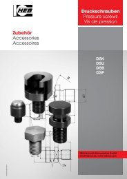
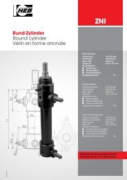
Verriegelungs-Zylinder<br />
Locking cylinder<br />
Vérin de verrouillage<br />
<strong>VZS251</strong><br />
<strong>VZS251</strong>NI<br />
Verriegelungs-Zylinder<br />
Nenndruck: 250 bar<br />
Prüfdruck: 350 bar<br />
Max. Hub: 3000 mm<br />
Kolben Ø: 32 bis 125 mm<br />
Einsatzgebiet:<br />
• Formenbau<br />
• Werkzeugbau<br />
• Vorrichtungsbau<br />
Endlagenabfrage: als <strong>VZS251</strong>NI<br />
Locking cylinder<br />
Nominal pressure: 250 bar<br />
Test pressure: 350 bar<br />
Max. stroke: 3000 mm<br />
Piston Ø: 32 to 125 mm<br />
Application area:<br />
• Mould-making<br />
• Tool manufacturing<br />
• Fixture<br />
Sensing of end position: as <strong>VZS251</strong>NI<br />
Vérin de verrouillage<br />
Pression nominale: 250 bar<br />
Pression de contrôle: 350 bar<br />
Max. Course: 3000 mm<br />
Piston Ø: 32 à 125 mm<br />
Domain d’utilisation:<br />
• Construction de moulages<br />
• Construction d’outillage<br />
• Construction de fixations<br />
Détection de fin de course: en <strong>VZS251</strong>NI<br />
<strong>HEB</strong> <strong>Hydraulik</strong>-<strong>Elementebau</strong> <strong>GmbH</strong><br />
info@heb-zyl.de, www.heb-zyl.com
Allgemeine Beschreibung<br />
und Hinweise<br />
• Das Prinzip des <strong>HEB</strong> Verriegelungszylinders<br />
entspricht einer formschlüssigen,<br />
mechanischen Verriegelung der ausgefahrenen<br />
Kolbenstange in der Hubendstellung<br />
(Hubtolleranz nach DIN ISO<br />
2768) durch spezielle Verriegelungs- und<br />
Sicherungselemente, so dass ein theoretisch<br />
starres Verbindungselement entsteht.<br />
Bewegte Einzelteile, Fertigungstoleranzen<br />
und die Elastizität von<br />
Kolbenstange und Verriegelungszange<br />
bewirken naturgemäß ein elastisches<br />
Federn des Verriegelungszylinders unter<br />
Last. Die Größenordnung dieser Federwirkung<br />
ist aus dem Diagramm auf Seite<br />
4 zu ersehen. Mit Hilfe der Kontermutter<br />
können Zylinderanschlag und externer<br />
Anschlag aufeinander abgestimmt werden.<br />
• Funktion: Automatische, federbetätigte<br />
Verriegelung.<br />
• Bauweise: runde Grundbauform,<br />
Schraubkonstruktion – Anschluß am<br />
Zylinderboden radial, in Flucht zum stangenseitigen<br />
Anschluß. Lieferbar in der<br />
Funktionsart doppeltwirkend, Dämpfung<br />
auf der Bodenseite (hinten) möglich.<br />
• Serienmäßig elektronische Verriegelungsüberwachung,Näherungsinitiatoren<br />
mit Winkelstecker.<br />
• Serienmäßig mit Entlüftungsschrauben<br />
für Schlauchanschluß.<br />
• Kolben-Ø 32 mm – 125 mm.<br />
• Hübe nach Kundenwunsch von 9 mm –<br />
3000 mm, Hubtoleranz nach DIN ISO<br />
2768. Für maximale Hublängen bitte die<br />
zulässige Knickbelastung der Kolbenstangen<br />
beachten.<br />
• Zulässige Kolbengeschwindigkeit in<br />
Verriegelungsrichtung 0,1m/sec. Höhere<br />
Kolbengeschwindigkeiten sind bei<br />
genauer Kenntnis der Betriebsbedingungen<br />
und Betriebsverhältnisse möglich.<br />
Bitte anfragen.<br />
• Die eingebauten Dichtungen sind für<br />
Hydroflüssigkeiten der Typen H, HL, HLP<br />
nach DIN 51524 / 51525, und den Temperaturbereich<br />
von -20˚C bis +90˚C geeignet.<br />
Bei höheren Temperaturen und<br />
anderen Druckmedien können entsprechende<br />
Dichtungswerkstoffe eingesetzt<br />
werden.<br />
• Betriebsdruck – Nenndruck 250 bar,<br />
Prüfdruck statisch 340 bar.<br />
• Kolbenstangenlauffläche gehärtet und<br />
hartverchromt, geschliffen und poliert,<br />
serienmäßige Ausrüstung mit Staubabstreifer.<br />
• Kolbendichtung aus PTFE.<br />
• Stangendichtung aus PU sowie PTFE.<br />
2<br />
General description<br />
and instructions<br />
• The operating principle of the <strong>HEB</strong><br />
locking cylinders consits of positive<br />
mechanical locking of the extended piston<br />
rod at the full limit of its stroke (stroke tolerance<br />
in accordance with DIN ISO 2768) by<br />
means of special locking and securing elements.<br />
This yields a theoretically rigid<br />
connecting element. Narurally, the individual<br />
moving parts, manufacturing tolerances<br />
and elasticity of the cylinder rod and<br />
locking mechanism cause the loaded cylinder<br />
to have a certain amount of elastic resilience<br />
under load.<br />
The magnitude of this resilience can be<br />
determined using the diagram shown on<br />
Page 4. The rod-end locknut can be used<br />
to align the cylinder stop position to the<br />
external stop position.<br />
• Operation: automatic, spring-actuated<br />
locking.<br />
• Construction: basic form cylindrical,<br />
threaded construction; radial connection to<br />
cylinder base, alligned with connection in<br />
piston-rod end cap. Available with doubleacting<br />
operation, optionally with cushioning<br />
at the base end (rear).<br />
• Electronic lock monitoring and proximity<br />
sensors with angle plugs fitted as standard.<br />
• Bleeder screws for hose connection fitted<br />
as standard.<br />
• Piston diameter 32 mm to 125 mm.<br />
• Stroke 9 mm to 3000 mm per customer<br />
requirement; stroke tolerance per DIN ISO<br />
2768. Please note the permissible buckling<br />
load of the piston rod for maximum stroke<br />
length.<br />
• Permissible piston speed in the locking<br />
direction: 0,1 m/s. Higher piston speeds<br />
are possible if the exact operating conditions<br />
and relationships are known. Please<br />
enquire.<br />
• The seals incorporated in the cylinder<br />
are suitable for use with type H, HL, and<br />
HLP hydraulic fluids in accordance with<br />
DIN 51524 / 51525, within the temperature<br />
range -20°C to +90°C. For temperatures<br />
above this range and other types of<br />
hydraulic fluids, suitable seal materials can<br />
be used.<br />
• Operating pressure (rated pressure) 250<br />
bar; test pressure (static) 340 bar.<br />
• Piston rod bearing surfaces are hardened<br />
and hard-chrome-plated, ground and<br />
polished. A dust wiper is fitted as standard.<br />
• Piston seal PTFE.<br />
• Rod seal PU or PTFE.<br />
Description et informations<br />
générales<br />
• Le principe du vérin hydraulique <strong>HEB</strong><br />
correspond à une verrouillage mécanique,<br />
claboté de la tige de vérin sortie dans la<br />
position finale de la course (tolérance de<br />
course selon la norme DIN ISO 2768) grâce<br />
à des élements particuliers de verrouillage et<br />
de sécurité de manière à obtenir un élément<br />
de liaison rigide sur le plan théorique. Les<br />
différentes pièces déplacées, les tolérances<br />
de fabrication et l’élasticité de la tige du vérin<br />
et de la pince de verrouillage entraînent<br />
naturellemnt un retour élastique du vérin de<br />
verrouillage lorsqu’il est en charge.<br />
L’ordre de grandeur de cet effet élastique<br />
est visible dans le diagramme à la page 4.<br />
A l’aide du contre-écrou, la butée du vérin<br />
et la butée externe peuvent être ajustées<br />
l’une à l’autre.<br />
• Fonctionnement: verrouillage automátique,<br />
commandé par ressorts.<br />
• Mode de construction: forme de construction<br />
de base circulaire, construction<br />
par assemblage par vis, raccord radial sur<br />
le fond du vérin, aligné sur le raccord côté<br />
tige, disponible avec le type de fonctionnement<br />
à effet double, amortissement<br />
possible sur le côté du fond (à l’arrière).<br />
• Surveillance électronique du verrouillage<br />
équipée en série, détecteurs de proximité<br />
avec fiches coudées.<br />
• Équipée en série des vis de purge pour<br />
le raccord tuyau.<br />
• Vérin 32 mm – 125 mm.<br />
• Courses en fonction des souhaits du client,<br />
de 9 mm à 3000 mm, tolérance de<br />
course selon la norme DIN ISO 2768. Pour<br />
la longueur de course maximum, respecter<br />
en plus la contrainte de flambage admissible<br />
de la tige du vérin.<br />
• Vitesse admissible du vérin en direction<br />
du verrouillage: 0,1 m/sec. Des vitesses<br />
supérieures du vérin sont possibles avec<br />
une connaissance précise des conditions<br />
d’exploitation et des rapports d’exploitation.<br />
Contacter la société.<br />
• Les joints intégrés sont prévus pour des<br />
liquides hydrauliques des types H, HL,<br />
HLP selon la norme DIN 51524 / 51525 et<br />
une plage de température de -20°C à<br />
+90°C. En cas de températures plus élevées<br />
et d’utilisation d’autres fluides sous<br />
pression, des matériaux d’étanchéité adéquats<br />
peuvent être utilisés.<br />
• Pression de service – pression nominale<br />
250 bars, pression de contrôle 340 bars<br />
statiques.<br />
• Surface de contact de la tige du vérin<br />
trempée et chromée dur, meulée et polie,<br />
équipement de série avec un racloir de<br />
poussières.<br />
• Joint du vérin en PTFE.<br />
• Joint de la tige en PU et PTFE.<br />
<strong>HEB</strong> <strong>Hydraulik</strong>-<strong>Elementebau</strong> <strong>GmbH</strong> / Tel. (0761) 1 30 99-0, Fax (0761) 13 50 66<br />
<strong>VZS251</strong>
<strong>VZS251</strong><br />
Sonderausstattungen<br />
• NI – Ausführung mit Näherungsinitiatoren<br />
für berührungslose Überwachung<br />
der Kolbenendlage.<br />
• S0 – Ausführung ohne elektronische<br />
Verriegelungsüberwachung.<br />
• S5 – Hochhitzebeständige Dichtungen<br />
für Hydroflüssigkeiten der Typen H, HL,<br />
HLP – Din 51524 / 51525 und Temperaturenab<br />
+100°C bis +200°C.<br />
• S10 – Näherungsinitiatoren mit Geradestecker.<br />
Funktionsbeschreibung Functional description Description du fonctionnement<br />
<strong>VZS251</strong>NI<br />
(NI = Sonderausstattung)<br />
• Grundstellung: Zylinder eingefahren,<br />
Schalter S1 (nur bei NI) = Signal.<br />
• Verriegelungsstellung: Anschluss A1<br />
wird druckbeaufschlagt, Zylinder fährt<br />
aus und wird verriegelt, Schalter S2 und<br />
S3 = Signal.<br />
• Über eine Reihenschaltung von S2 und<br />
S3 wird die exakte Verriegelung überwacht.<br />
• Zurück in Grundstellung: Anschluss A2<br />
wird druckbeaufschlagt, Zylinder wird<br />
entriegelt und fährt in Grundstellung,<br />
Schalter S2 und S3 = Nullsignal, Schalter<br />
S1 (nur bei NI) = Signal.<br />
Achtung: Wird nach Erreichen der Grundstellung<br />
der Anschluss A2 drucklos<br />
geschaltet, wird der Schalter S3 konstruktiv<br />
bedingt auf Signal gesetzt. Dies ist bei<br />
einer Reihenschaltung von S2 und S3<br />
ohne Auswirkungen auf die Steuerung.<br />
• Verriegelungszylinder müssen unbedingt<br />
auf der Verriegelungsseite auf den<br />
internen Anschlag im Zylinder gefahren<br />
werden, um exakt verriegeln zu können.<br />
• Beim Verriegelungsvorgang darf am<br />
Anschluss A2 kein Druck anstehen.<br />
<strong>VZS251</strong>NI<br />
Special equipments<br />
• NI – Version with proximity switches for<br />
non-contact monitoring of piston endposition.<br />
• S0 – Version without electronic lock monitor.<br />
• S5 – High heat-resistant seals for<br />
hydraulic fluids type H, HL, HLP – German<br />
Standard DIN 51524 / 51525 and for temperatures<br />
from +100˚C up to +200˚C.<br />
• S10 – Proximity sensors with straight<br />
plug.<br />
<strong>VZS251</strong>NI<br />
(NI = special equipment)<br />
• Initial position: Cylinder retracted, switch<br />
S1 (only with NI) = signal.<br />
• Locking position: Connection A1 is acted<br />
on by pressure, cylinder extends and locks,<br />
switch S2 and S3 = signal.<br />
• The precise locking operation is monitored<br />
via a series connection of S2 and S3.<br />
• Back to initial position: Connection A2 is<br />
acted on by pressure, cylinder is released<br />
and returns to its initial position, switch S2<br />
and S3 = zero signal, switch S1 (only with NI)<br />
= signal.<br />
Caution: If connection A2 is without pressure<br />
when the initial position is reached, the<br />
constructional design causes switch S3 to<br />
be set to signal. With a series connection of<br />
S2 and S3 this has no effect on the control.<br />
• On the locking side it is essential that<br />
locking cylinders are run to the internal<br />
contact side of the cylinder in order to enable<br />
correct locking.<br />
• During the locking process connection A2<br />
must not be under pressure.<br />
Equipements spéciaux<br />
• NI – Version avec initiateurs de proximité<br />
pour surveillance sans contact de la<br />
fin de course de piston.<br />
• S0 – Version sans surveillance électronique<br />
du verrouillage.<br />
• S5 – Garnitures résistantes aux températures<br />
très élevées pour liquides type H,<br />
HL, HLP – DIN 51524 / 51525 et des<br />
températures de +100˚C jusqu`à +200˚C.<br />
• S10 – détecteur de proximitéavec<br />
connecteur droit.<br />
<strong>VZS251</strong>NI<br />
(NI = équipement spécial)<br />
• Position de base : cylindre rentré, commutateur<br />
S1 (uniquement sur NI) = signal.<br />
• Position de verrouillage : Le raccord A1<br />
est pressurisé, le cylindre sort et est verrouillé,<br />
commutateur S2 et S3 = signal.<br />
• Le verrouillage correct est surveillé par un<br />
couplage en série de S2 et S3.<br />
• Retour à la position de base : Le raccord<br />
A2 est pressurisé, le cylindre est déverrouillé<br />
et se place en position de base, commutateur<br />
S2 et S3 = signal zéro, commutateur<br />
S1 (uniquement sur NI) = signal.<br />
Attention : Si après arrivée en position de<br />
base, le raccord A2 est commuté sans pression,<br />
le commutateur S3 sera placé sur signal<br />
en fonction de sa construction. Ceci n'a<br />
aucun effet sur la commande dans le cas<br />
d'un couplage en série de S2 et S3.<br />
• Les cylindres de verrouillage doivent<br />
impérativement être entrés dans le cylindre<br />
sur le côté verrouillage sur l'arrêt interne<br />
pour pouvoir se verrouiller correctement.<br />
• Durant le processus de verrouillage, il ne<br />
doit y avoir aucune pression au raccord A2.<br />
e-mail: info@heb-zyl.de / homepage: http://www.heb-zyl.com 3
Funktionsart Mode of operation Mode de fonctionnement<br />
Sinnbild • Symbol DIN-ISO 1219/1 Bezeichnung • Order specification • Référence de commande Beschreibung • Description<br />
doppeltwirkend<br />
206 double acting<br />
à double effet<br />
Technische Daten • Technical data • Caractéristiques techniques<br />
Kolben-Ø mm<br />
Piston-Ø mm<br />
Piston-Ø mm<br />
Kolbenstangen-Ø mm<br />
Piston-rod Ø mm<br />
Tige de piston Ø mm<br />
Kolbenfläche stoßend cm2 Piston face pushing cm2 Surface de piston poussante cm2 100 bar 150 bar 200 bar 250 bar 100 bar 150 bar 200 bar 250 bar VZS<br />
32 18 8,04 804 1200 1600 2010 5,49 540 820 1090 1220 3000 9<br />
40 22 12,76 1250 1880 2510 3140 8,76 870 1310 1750 2190 4500 10<br />
50 28 19,63 1960 2940 3920 4900 13,47 1340 2020 2690 3360 7000 14<br />
63 36 31,16 3110 4670 6230 7790 20,99 2090 3140 4190 5240 10000 17<br />
80 45 50,24 5020 7530 10040 12560 34,36 3430 5150 6870 8590 18000 17<br />
100 56 78,50 7850 11780 15700 19620 53,90 5390 8080 10780 13470 25000 22<br />
125 70 122,70 12270 18400 24540 30670 84,23 8420 12630 16840 21050 40000 29<br />
• Kraft-Weg Diagramm<br />
• Technical table<br />
• Tableau technique<br />
Kolbenkraft stoßend – daN<br />
Piston force pushing – daN<br />
Force de piston poussante – daN<br />
Elastischer Weg der Kolbenstange in<br />
Abhängigkeit der Verriegelungskraft<br />
und des Kolben-Ø des Zylinders.<br />
(Richtwerte)<br />
Elastic travel dependent from the<br />
locking force and from the piston-Ø of<br />
the cylinder. (Standard values)<br />
Chemin élastique de la tige de piston en<br />
dépendance de la force de verrouillage<br />
et du diamètre du piston du cylindre.<br />
(Valeurs indicatives)<br />
Verriegelungskraft (kN) •<br />
Locking force (kN) • Force de verrouillage (kN)<br />
Kolbenfläche ziehend cm2 Piston face drawing cm2 Surface de piston tirante cm2 Kolbenkraft ziehend – daN<br />
Piston force drawing – daN<br />
Force de piston tirante – daN<br />
Elast. Weg (mm) •<br />
Elastic travel (mm) • Chemin élastique (mm)<br />
4 <strong>HEB</strong> <strong>Hydraulik</strong>-<strong>Elementebau</strong> <strong>GmbH</strong> / Tel. (0761) 1 30 99-0, Fax (0761) 13 50 66<br />
<strong>VZS251</strong><br />
Verriegelungskraft (daN)<br />
Locking force (daN)<br />
Force de verrouillage (daN)<br />
Mindesthub<br />
Stroke min.<br />
course min.
<strong>VZS251</strong><br />
Technische Daten zu den induktiven Näherungsschaltern S1, S2 und S3<br />
Technical data for the inductive proximity sensors S1, S2 and S3<br />
Caracteristiques techniques pour les détecteurs de proximité inductif S1, S2 et S3<br />
S3<br />
PNP-Schließer / plusschaltend<br />
PNP-Normally-open / positive sensing<br />
PNP contact à fermeture / commutation positive<br />
Nennschaltabstand S N Nominal sensing distance S N Portée nominale S N 1,5 mm<br />
Arbeitsabstand S a Operating zone S a Portée de travail S a 0 ... 1,2 mm<br />
Spannungsabfall (Ie) voltage drop (Ie) chute de tension (Ie) ≤ 2 V<br />
Betriebsspannung U B Supply voltage U B Tension d’emploi U B 10 ... 30 VDC<br />
Restwelligkeit Ripple Ondulation résiduelle ≤ 15%<br />
Strombelastbarkeit Ie Load current Ie Courant admissible Ie 200 mA<br />
Schaltfrequenz f max. Switching frequency max. Fréquence max. de commutation 1000 Hz<br />
kurzschlußfest Short circuit protected Protection contre les courtscircuits ja / yes / oui<br />
Gehäusewerkstoff Housing material Matérial du boîter N° 1.4104<br />
Umgebungstemperatur Ambient operation temperature Temperature d’emploi -25°C ... +70°C<br />
Steckverbinder (s. u.) Plug connection (see below) Connecteur (voir ci-dessous) S4 / S10<br />
Hochdruckfest bis High pressure rated to 500 bar Résistant aux pression de jusq’à<br />
500 bar an aktiver Fläche. of the active surface. 500 bar au droit de la face sensible.<br />
Schutzart IP 68 Protection class IP 68 of the Degré de protectionIP 68 au droit<br />
an aktiver Fläche. active surface. de la face sensible.<br />
Bestellbezeichnung Order specification Référence de commande BES-S-01<br />
Lieferbare Steckverbindungen • Available plug connections • Connecteurs livrables<br />
Winkelsteckverbinder „S4“<br />
Angular plug “S4“<br />
Connecteur coudé “S4“<br />
–<br />
Last / burden / charge<br />
+<br />
blau (–) / blue (–) / bleu (–)<br />
Bestellbezeichnung für Ersatzbeschaffung BKS - S4<br />
Order specification for replacement order BKS - S10<br />
Référence de commande pour le remplacement des dètecteurs compacts électroniques<br />
schwarz = Schaltkontakt<br />
black = Switch contact<br />
noir = contact de commutation<br />
braun (+) / brown (+) / brun (+)<br />
Nennschaltabstand SN Nominal sensing distance SN Portée nominale SN 2 mm<br />
Arbeitsabstand Sa Operating zone Sa Portée de travail Sa 0 ... 1,6 mm<br />
Spannungsabfall (Ie) voltage drop (Ie) chute de tension (Ie) ≤ 2,5V<br />
Betriebsspannung UB Supply voltage UB Tension d’emploi UB 12 ... 30 VDC<br />
Restwelligkeit Ripple Ondulation résiduelle ≤ 15%<br />
Strombelastbarkeit Ie Load current Ie Courant admissible Ie 200 mA<br />
Schaltfrequenz f max. Switching frequency max. Fréquence max. de commutation 1200 Hz<br />
kurzschlußfest Short circuit protected Protection contre les courtscircuits ja / yes / oui<br />
Gehäusewerkstoff Housing material Matérial du boîter N° 1.4104<br />
Umgebungstemperatur Ambient operation temperature Temperature d’emploi -25°C ... +70°C<br />
Steckverbinder (s. u.) Plug connection (see below) Connecteur (voir ci-dessous) S4 / S10<br />
Bestellbezeichnung Order specification Référence de commande BES-S-02<br />
S1+ S2<br />
PNP-Schließer / plusschaltend<br />
PNP-Normally-open / positive sensing<br />
PNP contact à fermeture / commutation positive<br />
–<br />
Last / burden / charge<br />
+<br />
blau (–) / blue (–) / bleu (–)<br />
schwarz = Schaltkontakt<br />
black = Switch contact<br />
noir = contact de commutation<br />
braun (+) / brown (+) / brun (+)<br />
Geradesteckverbinder „S10“<br />
Straight plug “S10“<br />
Connecteur droit “S10“<br />
e-mail: info@heb-zyl.de / homepage: http://www.heb-zyl.com 5
Befestigungsarten Fixation systems Modes de fixation<br />
Stangenseitige Verriegelung<br />
Rod-side locking<br />
Verrouillage côté tige<br />
6<br />
Sintermetallfilter<br />
sintered metal filter<br />
filtre en métal fritté<br />
VZS<br />
Option VZS-NI<br />
Option VZS-NI<br />
Ident.Nr.<br />
Ident.No.<br />
Ident.No.<br />
101<br />
102<br />
Beschreibung<br />
Description<br />
Description<br />
• Gewindebefestigung<br />
• Thread fixation<br />
• Fixation par filet<br />
<strong>HEB</strong> <strong>Hydraulik</strong>-<strong>Elementebau</strong> <strong>GmbH</strong> / Tel. (0761) 1 30 99-0, Fax (0761) 13 50 66<br />
• Gewindebohrungen<br />
stirnseitig<br />
• Thread borings frontal<br />
• Alésages de filet sur la face<br />
<strong>VZS251</strong>
<strong>VZS251</strong><br />
Befestigungsarten Fixation systems Modes de fixation<br />
Stangenseitige Verriegelung<br />
Rod-side locking<br />
Verrouillage côté tige<br />
VZS<br />
Option VZS-NI<br />
Option VZS-NI<br />
Option VZS-NI<br />
Ident.Nr.<br />
Ident.No.<br />
Ident.No.<br />
Beschreibung<br />
Description<br />
Description<br />
• Flansch vorn<br />
• Flange in front<br />
• Bride au front<br />
• Flansch hinten<br />
• Flange in the rear<br />
• Bride au dos<br />
e-mail: info@heb-zyl.de / homepage: http://www.heb-zyl.com 7<br />
103<br />
105<br />
111<br />
• Schwenkauge mit<br />
Gelenklager<br />
• Pivot lug with spherical bearing<br />
• Oeillet pivotant avec<br />
palier à rotule
Baumaße Construction measures Mesures de construction<br />
piston-ø mm<br />
d1-ø 40 50 65 83 100 125 150<br />
d2-ø 18 22 28 36 45 56 70<br />
d2G M16x1,5 M20x1,5 M27x1,5 M35x1,5 M42x1,5 M52x1,5 M65x1,5<br />
d3-ø 52 65 80 100 125 150 180<br />
d3G M62x1,5 M75x1,5 M85x1,5 M110x2 M130x2 M150x2 M200x2<br />
d5-ø 14 14 18 18 22 22 26<br />
d6-ø 11 14 14 18 18 22 22<br />
d7-ø 25 30 40 50 60 70 90<br />
d9 M6 M8 M8 M10 M12 M16 M20<br />
d10-øf7 50 50 68 86 95 118 150<br />
d11-ø 60 71 82 104 120 148 190<br />
d12-ø 70 82 95 120 140 170 220<br />
d19-ø 60 70 85 110 125 156 200<br />
L0 + Hub 194 202 237 277 308 394 482<br />
L01 + stroke 194 202 237 283 313 399 486<br />
L02 + course 229 241 289 345 391 494 597<br />
L2 164 170 203 245 273,5 353 435<br />
L3 58 72 98 126 152 175 210<br />
L4 40 50 70 90 110 130 160<br />
L5 12 16 16 20 25 32 40<br />
L6 16 20 25 35 40 48 60<br />
L7 3 3 4 4 5 5 6<br />
L9 20 25 34 42 50 65 80<br />
L10 53 51 64 71 75 85 91<br />
L11 118 125 139 183 196,5 278 327<br />
L12 50 50 60 60 65 75 90<br />
L13 35 42 52 62 78 95 115<br />
L14 12,5 12,5 15,5 17,5 20 22,5 24<br />
L16 25 25 30 35 40 45 48<br />
L17 50 50 60 66 70 80 95<br />
L19 15 13 17 18 19 20 20<br />
L20 131 135 161 198 223,5 294 360<br />
L21 32,5 38,5 46 58 62 86 105<br />
L22 18 18 18 18 20 22 22<br />
L23 32 39 46 52 62 75 93<br />
L25 103 107 113 117 129 138 15<br />
b3 62 70 80 96 115 130 160<br />
b4 90 100 110 130 150 170 200<br />
b5 70 80 96 115 130 160 210<br />
b6 100 110 130 150 170 200 270<br />
b8 16 18 22 28 36 40 50<br />
b9 20 22 28 35 44 49 60<br />
R 30 35 42,5 55 62,5 78 100<br />
A G3/8 G3/8 G1/2 G1/2 G1/2 G1/2 G3/4<br />
SW 24 30 41 55 65 80 95<br />
<strong>VZS251</strong> Kolben-ø mm 32 40 50 63 80 100 125<br />
e-mail: info@heb-zyl.de / homepage: http://www.heb-zyl.com 8
Ersatzteile Spare parts Pièces détachées<br />
9<br />
POS. Stück • piece • pièce Ersatzteile • Spare parts • Pièces détachées<br />
01 1 Abstreifer • Wiper • Racloir<br />
02 1 Stangendichtung • Rod seal • Garniture de la tige<br />
03 1 Stangendichtung • Rod seal • Garniture de la tige<br />
04 1 Kolbendichtung • Piston seal • Garniture du piston<br />
05 1 Kolbendichtung • Piston seal • Garniture du piston<br />
06 1 Stangenführungsring • Rod guide ring • Bagues de guidage de la tige<br />
07 2 Kolbenführungsring • Piston guide ring • Bagues de guidage du piston<br />
08 1 Kolbenführungsring • Piston guide ring • Bagues de guidage du piston<br />
09 2 O-Ring • O-ring • Joint torique<br />
15 1 Führungskopf • Guide end cap • Tête de guidage<br />
16 1 Anschlagmutter • Rod end nut • Ecrou de butée<br />
17 1 Zuhaltekolben • Holding piston • Vérin de verrouillage<br />
18 1 Kolben • Piston • Verrouillage<br />
19 1 Einsatz-Verriegelung • Lock insert • Insert<br />
20 1 Verschraubung • Gland • Raccord à vis<br />
21 1 Kolbenstange • Piston rod • Tige du piston<br />
22 1 Anschlagscheibe • Stop washer • Rondelle de butée<br />
23 1 Zylinderrohr • Cylinder tube • Tube cylindrique<br />
27 1 Boden • Base • Fond<br />
30 2 Entlüftungsschraube • Bleeder screw • Vis de purge<br />
31 1 NI-Adapter • NI-adapter • Adapteur NI<br />
34 1 Sicherungsring DIN 472 • Retaining ring DIN 472 • Bague de sécutité, DIN 472<br />
35 1 Gewindestift DIN 914 • Grub screw DIN 914 • Tige filetée, DIN 914<br />
38 1 Druckfeder • Compression spring • Ressort de pression<br />
40 2 Schalter BES-S-01 • Switch BES-S-01 • Commutateur, BES-S-01<br />
41 1 Schalter BES-S-02 • Switch BES-S-02 • Commutateur, BES-S-02<br />
42 1 Sintermetallfilter • Sintered metal filter • Filtre en métal fritté<br />
<strong>HEB</strong> <strong>Hydraulik</strong>-<strong>Elementebau</strong> <strong>GmbH</strong> / Tel. (0761) 1 30 99-0, Fax (0761) 13 50 66<br />
<strong>VZS251</strong>
Verriegelungs-Zylinder / Locking cylinder / Vérin de verrouillage<br />
Typenschlüssel Code Clé des types<br />
Anhand der lieferbaren Befestigungsund<br />
Funktionsarten kann der gewünschte<br />
Zylindertyp gemäß folgendem<br />
Schlüssel festgelegt werden:<br />
By means of the deliverable fixation<br />
systems and modes of operation the desired<br />
cylinder type can be fixed according<br />
to the following code:<br />
<strong>VZS251</strong><br />
<strong>VZS251</strong>NI<br />
Au moyen des modes de fixation et<br />
de fonctionnement livrables le type de<br />
cylindre désiré selon la clé suivante:<br />
Bezeichnung • Order specification • Référence de commande VZS 251 NI S0 101 63 36 200 206 S10<br />
Zylindertyp und Betriebsdruck<br />
Cylinder type and Operating pressure<br />
Type de cylindre et Pression de fonctionnement<br />
mit Näherungsinitiatoren zur Überwachung der Kolbenendlage<br />
with proximity sensors for the control of the stroke end<br />
avec détecteurs de proximité pour le contrôle de la fin de course<br />
Ohne elektronische Verriegelungsüberwachung •<br />
Without electronic locking control • Sans contrôle de verrouillage électronique<br />
Befestigungsart • Fixation system • Mode de fixation<br />
Kolben Ø mm • Piston Ø mm • Ø piston mm<br />
Kolbenstangen Ø mm • Piston-rod Ø mm • Ø Tige de piston mm<br />
Hub • Stroke • Course<br />
Funktionsart • Mode of operation • Mode de fonctionnement<br />
Sonderausstattung • Special equipment • Equipement spéciale<br />
Bestellbeispiel Example of order Exemple de commande<br />
<strong>VZS251</strong> - NI - S0 - 101 - 63 / 36 / 200 - 206 / S10<br />
<strong>HEB</strong>-Verriegelungszylinder<br />
für Betriebsdruck bis 250 bar, ausgerüstet<br />
mit Näherungsinitiatoren zur berührungslosen<br />
Überwachung der Kolbenendlage, ohne<br />
elektronische Verriegelungsüberwachung.<br />
101 = Gewindebefestigung.<br />
Kolben-Ø 63 mm, Kolbenstangen-Ø 36 mm,<br />
Hub 200 mm.<br />
206 = doppeltwirkend.<br />
S10 = Sonderausstattung –<br />
mit Geradestecker<br />
10<br />
Änderungen vorbehalten.<br />
Subject to change without notice.<br />
Modification resérvée.<br />
<strong>HEB</strong> locking cylinder<br />
for operating pressure up to 250 bar, fitted<br />
with two proximity sensors for the<br />
control of the stroke end, without electronic<br />
locking control .<br />
101 = Thread fixation.<br />
Piston Ø 63 mm, Piston-rod Ø 36 mm,<br />
Stroke 200 mm.<br />
206 = double-acting<br />
S10 = special equipment –<br />
with straight plug<br />
<strong>HEB</strong> vérin de verrouillage pour pression de<br />
fonctionnement jusqu’- à 250 bar, équipé<br />
de détecteur de proximité pour le contrôle<br />
de la fin de course, sans contrôle de verrouillage<br />
électronique.<br />
101 = Fixation par filet.<br />
Ø Piston 63 mm, Ø Tige de piston 36 mm,<br />
Course 200 mm.<br />
206 = à double effet.<br />
S10 = équipement spécial -<br />
avec connecteur droit.<br />
Sämtliche Zylinder unserer Fertigung sind mit genauer Typenbezeichnung bzw. Ident.Nr. und der Kom.Nr., die zusätzlich eingeschlagen<br />
wird, gekennzeichnet. Eine absolut einwandfreie Identifizierung bei Ersatzteilbeschaffung und Ersatzteilbezug ist hierdurch gewährleistet.<br />
All cylinders of our production are provided with the exact order specification respectively the number of identification and the commission<br />
number which is additionally stamped on the cylinder. By this an absolutely perfect identification in case of order and purchase of spare<br />
parts is guaranteed.<br />
Tous les cylindres de notre production sont marqués avec la référence de commande exacte ou bien le numéro d’identification et le numéro<br />
de commission qui est estampé additionnellement. Une identification absolument correcte pour l’acquisition des éléments de rechange est<br />
garantie par cela.<br />
Achtung – Typenbezeichnung bzw. Ident.Nr. sowie Kom.Nr. bei Ersatzbeschaffung und<br />
Ersatzteilbezug unbedingt angeben.<br />
Attention – In case of order and purchase of spare parts it is absolutely necessary to indicate<br />
the order specification or the number of identification as well as the commission number.<br />
Attention – En cas d’acquisition des éléments de rechange indiquer absolument la référence<br />
de commande ou bien le numéro d’identification ainsi que le numéro de commission.<br />
<strong>HEB</strong> <strong>Hydraulik</strong>-<strong>Elementebau</strong> <strong>GmbH</strong> / Tel. (0761) 1 30 99-0, Fax (0761) 13 50 66<br />
<strong>VZS251</strong>