Gas Springs - PMCCatalogue
Gas Springs - PMCCatalogue
Gas Springs - PMCCatalogue

You also want an ePaper? Increase the reach of your titles
YUMPU automatically turns print PDFs into web optimized ePapers that Google loves.
GAS SPRINGS<br />
MOLLE A GAS<br />
RESSORTS A GAZ<br />
AISI 316 L and ALUMINIUM<br />
cat. 2006/MG
PRESSMAIR srl<br />
INDUSTRIAL PNEUMATIC COMPONENTS<br />
APPARECCHIATURE PNEUMATICHE INDUSTRIALI<br />
44045 Renazzo di Cento (Ferrara) ITALY - Via Pasquino, 29/a<br />
PH. ++39.051.900122 - Fax ++39.051.909635<br />
www.pressmair.com e-mail: pressmair@tiscali.it
GAS SPRINGS<br />
MANUFACTURER’S DECLARATION<br />
DICHIARAZIONE DEL FABBRICANTE<br />
DECLARATION DU FABRICANT<br />
The Undersigned PRESSMAIR SRL, Via Pasquino 29/A, 44045 Renazzo di Cento, Ferrara,<br />
Italy, declares under its own responsability that ALL PRODUCTS AND COMPONENTS<br />
illustrated in this Catalogue and therein described, are intended to be incorporated into<br />
a machinery subject to the application of the 89/392/CEE Directive and subsequent<br />
amendments apply.<br />
Commissioning of the component or system shall be forbidden until the machinery, into<br />
the component is to be incorporated, is declared to comply with the EEC directive.<br />
Ing. Rodolfo Musci<br />
Managing Director<br />
La Sottoscritta PRESSMAIR SRL, Via Pasquino 29/A, 44045 Renazzo di Cento, Ferrara, Italia,<br />
dichiara sotto la propria responsabilità che TUTTI I PRODOTTI E I COMPONENTI illustrati<br />
sul presente catalogo ed in esso descritti, sono destinati ad essere incorporati in macchine<br />
a cui si applica la Direttiva 89/392/CEE e suoi successivi emendamenti.<br />
La messa in funzione del componente o del sistema è vietata prima che la macchina<br />
in cui verrà incorporato venga dichiarata conforme alle disposizioni della direttiva.<br />
Ing. Rodolfo Musci<br />
Amministratore Delegato<br />
La Soussignée PRESSMAIR SRL, Via Pasquino 29/A, 44045 Renazzo di Cento, Ferrara, Italie,<br />
déclare sous sa propre responsabilité que TOUS LES PRODUITS ET LES COMPOSANTS<br />
compris et illustrés dans ce Catalogue, sont destinés á être incorporés dans une machine á<br />
laquelle s’applique la Directive 89/392/CEE et ses amendements successifs.<br />
La mise en fonction du composant ou système est interdite tant que la machine dans<br />
laquelle le composant ou système doit être incorporé n’aura pas été déclarée conforme à la<br />
directive.<br />
Ing. Rodolfo Musci<br />
Administrateur<br />
N.B.: The company reserves the right to make modifications - N.B.: Con riserva di modifiche - N.B.: Sous réserve de modification<br />
1
GAS SPRINGS<br />
GAS SPRINGS<br />
FOREWORD<br />
HOW IT WORKS<br />
A gas spring is essentially composed by a pipe case perfectly dry sealed, pressurized; inside the pipe case, a rod can move<br />
alternatively; a “pseudo-piston” is fixed to the rod; its function is only to avoid the exit of the rod from the pipe case, when<br />
it is pushed by the pressured gas. The gas spring’s working force can be calculated as the result of the gas pressure on the<br />
sole rod section. The gas spring rod always performs the total theoretical stroke, unless stopped before by a mechanical<br />
block.<br />
WHERE TO USE IT<br />
<strong>Gas</strong> springs can have many industrial utilizations: generally they act as a balance force for lifting doors, hatchways or doors;<br />
but they can be used as tension devices or shock absorbers.<br />
TYPICAL USE<br />
Apparatus’ doors - Boats hatchbacks - Apparatus protections - Rooflights - Heavy weight cover lift<br />
MOLLE A GAS<br />
INTRODUZIONE<br />
COME FUNZIONANO<br />
La molla a gas è costituita sostanzialmente da un involucro a perfetta tenuta, pressurizzato, all’interno del quale può scorrere con<br />
moto alternato uno stelo; sullo stelo è fissato un fermo (pseudo-pistone) che ha il solo scopo di impedire la fuoriuscita dello stelo<br />
stesso dall’involucro, quando questo è sottoposto alla spinta del gas pressurizzato. La forza resa dalla molla a gas è quella risultante<br />
dalla spinta della pressione di precarico sulla sola sezione dello stelo. La molla a gas esegue sempre la corsa teorica totale,<br />
se non incontra riscontri meccanici che la fermano prima.<br />
DOVE IMPIEGARE LE MOLLE A GAS<br />
Le molle a gas hanno diversi impieghi di tipo industriale: generalmente sono usate per bilanciare le forze di azionamento di sportelli<br />
a sollevamento, boccaporti e/o porte; esse possono essere anche usate come dispositivi di tensionamento o come ammortizzatori.<br />
IMPIEGHI PRINCIPALI<br />
Portelloni di protezione - Portelli imbarcazioni - Lucernari - Sollevamento di pesanti coperchi.<br />
RESSORTS A’ GAZ<br />
INTRODUCTION<br />
COMMENT ILS TRAVAILLENT<br />
Le ressort à gaz est essentiellement constitué par un tuyeau avec étenchéité parfaite, pressurisé, dans lequel est installée une tige<br />
qui peut bouger avec un mouvement alternatif; sur la tige est installé un arrêt (pséudo-piston) qui a le seul but de ne pas permettre<br />
la sortie de la tige du tuyeau, quand elle est poussée par la pression du gaz pressurisé. La force utile du ressort à gaz est le<br />
résultat de la pression chargée dans le tuyeau sur la surface de la section de la tige. Si la tige du ressort à gaz ne rencontre pas<br />
des arrêts mécaniques, elle fait toujours la course théorique complète.<br />
OU ON UTILISE LES RESSORTS A’ GAZ.<br />
Les ressorts à gaz ont plusieurs utilisations industrielles: en général ils sont employés pour balancer les forces nécessaires pour<br />
mouvoir les portières en ouverture, les écoutilles et/ou les portes; ils peuvent être imployés aussi comme dispositifs de tension et<br />
comme amortisateurs.<br />
UTILISATIONS PRINCIPALES<br />
Portelones de protection - Sabord d’acces sur les bateaux - Lucarnes - Mouvement des lourds couvercles.<br />
2<br />
N.B.: The company reserves the right to make changes - N.B.: Con riserva di modifiche - N.B.: Sous réserve de modification
GAS SPRINGS<br />
HOW TO CALCULATE GAS SPRINGS<br />
FOREWORD<br />
Due to its design, the gas spring can only PUSH along the rod axis (which can only push to exit and can not pull to enter,<br />
unless installed with a special cinematic mechanism); the available force is practically constant for the whole length of<br />
the stroke. So the gas spring can be used to balance a force (e.g. a weight force) acting along the rod axis; as shown in the<br />
following pictures, it is possible to understand that according to the difference between the involved forces and the difference<br />
between the distances of the application point of each force to the rotation fulcrum, it is possible to reach different<br />
equilibrium situations; the result is an easy displacement of a heavy object, when it rotates around a fixed rotation point.<br />
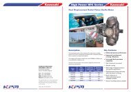
It is important to remember that the useful component of the total gas spring force is strictly related to the setting angle<br />
formed by the gas spring axis and the application line of the force to be contrasted; looking at the force/angles diagram,<br />
you can find for example:<br />
• Angle of 15°, the useful component is 96% of the total gas spring force (that is if gas spring has 250 N [about 25 Kg] of total<br />
force, the useful component is 250 N x 0.96= 240N [about 24 Kg])<br />
• Angle of 45°, the useful component is 71% , that is 240N x 0.71= 177.5 N (about 17,70 Kg)<br />
• Angle of 75°, the useful component is only 26% , that is 240N x 0.26= 65 N (about 6,5 Kg)<br />
It is easy to understand that the smaller is the angle, the bigger is the useful component of the force at the start of<br />
the operation. The suggested setting angle is around 30°.<br />
A small angle avoids also another problem: if it is necessary to install a strong gas spring due to a large initial setting angle,<br />
when the rotation is performed and the gas spring has a smaller setting angle, its useful component can be too strong to<br />
allow the reverse movement.<br />
GAS SPRING POWER CALCULATION<br />
Referring to fig. 2, the balance is reached when<br />
P x a = U x b<br />
Where the values are:<br />
P = Total value (denominated in Kg OR in N [Newton]) of the force to be contrasted, appliance point being the center of gravity.<br />
a = lever arm (denominated in meters) of the force to be contrasted (distance between the center of gravity and the rotation<br />
center)<br />
U = Useful component of the gas spring total force (as per “P” denominated in Kg OR in N) deduced from fig. 2, in connection<br />
with the gas spring setting angle.<br />
b = lever arm (as per “a” denominated in meters) of the useful component of the gas spring total force (distance between<br />
the center of application of the gas spring force and the rotation center).<br />
When the value of both equation’s part is equal, this is the balance point; all other conditions will show the supremacy either<br />
of the gas spring or of the force to be contrasted; the designer will operate a choice.<br />
PLEASE NOTE:<br />
The gas spring’s force value indicated in the following pages is related to the extended position rod.<br />
When the rod is positioned internally in the gas spring, the internal pressure rises and gas spring’s force is higher. The<br />
ratio between the forces (F1=Force with Rod Internally positioned; F2 = Force with Rod Externally positioned) is as follows:<br />
<strong>Gas</strong> spring Force value<br />
MG19 F1 = F2 x 1.3<br />
MG25 F1 = F2 x 1.5<br />
MG30 F1 = F2 x 1.5<br />
MG40 F1 = F2 x 1.5<br />
N.B.: The company reserves the right to make changes - N.B.: Con riserva di modifiche - N.B.: Sous réserve de modification<br />
3
GAS SPRINGS<br />
IL DIMENSIONAMENTO DELLE MOLLE A GAS<br />
PREMESSA.<br />
La molla a gas, per la sua concezione costruttiva, ha la caratteristica di esercitare una spinta lungo l’asse dello stelo (il quale spinge<br />
solo per uscire e non può essere utilizzato per tirare per entrare se non opportunamente istallato con un cinematismo meccanico);<br />
la forza esercitata si mantiene praticamente costante durante tutto lo sviluppo della corsa dello stelo.<br />
Perciò la molla a gas può essere impiegata per contrastare una forza (ad esempio un peso) che agisca nel senso dell’asse dello<br />
stelo; facendo riferimento ai disegni allegati, si ricava che a seconda della differenza delle due forze in gioco e delle distanze dei<br />
punti di fulcro, si possono ottenere varie situazioni di equilibrio e quindi c’è la possibilità di facilitare la movimentazione di oggetti<br />
pesanti che devono ad esempio ruotare attorno ad un centro di rotazione fisso.<br />
Occorre ricordare inoltre che il valore utile della componente della forza della molla a gas, dipende in maniera fondamentale<br />
dall’angolo che la molla a gas stessa forma rispetto all’asse di applicazione della forza da contrastare.<br />
In riferimento al diagramma delle forze e degli angoli allegato, si può notare che<br />
• se l’angolo formato è ad esempio di 15°, la componente utile è del 96% della forza totale della molla (es.: Molla a gas da 250 N<br />
(circa25 Kg), la forza utile residua è 250x0.96=240 N (circa 24 Kg)<br />
• se l’inclinazione è di 45° la forza residua è il 71% cioè 250N x 0,71 = 177.5 N (circa 17,5 KG)<br />
• se l’inclinazione è di 75°, la forza residua è solamente il 26% :250 N x.0,26 = 65 N (circa 6,5 Kg)<br />
Quanto sopra indica che un corretto posizionamento della molla a gas deve prevedere un angolo di applicazione rispetto all’asse<br />
della forza da contrastare non superiore ai 30°, al fine di evitare di incorrere nel problema di non riuscire a riportare l’oggetto nella<br />
sua posizione iniziale, a causa della elevata forza che la molla svilupperà se raggiungesse un angolo di applicazione più favorevole.<br />
CALCOLO DELLA POTENZA DELLA MOLLA A GAS<br />
L’equilibrio è governato dalla legge della leva di primo grado, che dice:<br />
P x a = U x b<br />
In cui si deve intendere:<br />
P = Valore totale (espresso in kg o N[Newton]) della forza da contrastare applicato nel baricentro del corpo.<br />
a = braccio di leva (espresso in metri) della forza da contrastare (distanza tra il baricentro e il punto di rotazione)<br />
U = Componente Utile della forza (espresso come P in kg o N) della molla a gas (calcolata dal diagramma in funzione dell’angolo<br />
di applicazione della molla a gas).<br />
b = braccio di leva (espresso come a in metri) della Componente Utile della forza della molla a gas (distanza del punto di applicazione<br />
della forza della molla a gas dal centro di rotazione).<br />
Quando il valore ricavato dalle due parti della equazione, è identico, siamo nel punto di equilibrio.<br />
In ogni altra situazione si avrà una prevalenza più o meno grande del peso da contrastare o della forza della molla a gas, che il progettista<br />
dovrà governare a sua scelta.<br />
NOTA<br />
Il valore della forza della molla a gas indicata nelle pagine seguenti, è relativa alla posizione della molla con stelo esteso. Quando<br />
lo stelo è rientrato, il valore della pressione interna, e quindi della forza della molla, aumenta.<br />
Il rapporto tra le due diverse forze (F1= forza della molla a gas con stelo rientrato; F2= forza della molla a gas con stelo esteso) è<br />
il seguente:<br />
Molla a gas Valore della forza<br />
MG19 F1 = F2 x 1.3<br />
MG25 F1 = F2 x 1.5<br />
MG30 F1 = F2 x 1.5<br />
MG40 F1 = F2 x 1.5<br />
4<br />
N.B.: The company reserves the right to make changes - N.B.: Con riserva di modifiche - N.B.: Sous réserve de modification
GAS SPRINGS<br />
CALCUL DES RESSORTS A’ GAZ<br />
PRÉFACE<br />
Les ressorts à gaz sont cunçus pour exercer une poussée suivante l’axe de la tige (ils peuvent seulement pousser pour sortir et<br />
ils ne peuvent pas être utilisés pour tirer à rentrer si non avec l’installation d’ un cinématisme mécanique); telle force est pratiquement<br />
constante pendant toute la course de la tige.<br />
Pourtant les ressorts à gaz peuvent être employés pour s’opposer à une force (pour exemple un poids) qui agit en opposition,<br />
suivant l’axe de la tige; par réference aux plans, on comprend facilement que, selon la difference entre les deux forces en<br />
considération et la différence entre les deux bras de levier, on peut obténir plusieures situations d’équilibre, et on peut pourtan pour<br />
exemple faciliter le mouvement d’objets lourds qui doit tourner autour d’un point de rotation fixe.<br />
Il faut rappeller que la valeur utile de la composante de la force du ressort à gaz, est déterminée par l’angle que le ressort à gaz<br />
lui même fait par rapport à l’axe d’application de la force à opposer.<br />
Par réference à la fig. 1 (diagram des forces et des angles), on voit que:<br />
• si l’angle est pour exemple de 15°, la composante utile est le 96 % de la force totale du ressort à gaz (exemple: si la force du ressort<br />
est 250 N [à peut près 25 Kg], la composante utile dans ce cas est 250N x 0,96= 240 N [à peut près 24 Kg])<br />
• si l’angle est de 45°, la composante utile est le 71 % de la force totale, c’est à dire 250 N x 0,71= 177,5 N (à peut près 17.5 Kg).<br />
• si l’angle est de 75°, la composante utile est seulement le 26 % de la force totale, c’est à dire 250 N x 0,26= 65N (à peut près<br />
6,5 Kg).<br />
On peut facilement comprendre pourtant que l’angle conseillé pour un correcte montage du ressort à gas est autour du 30°, par<br />
rapport à l’axe d’application de la force opposée; une telle application évite aussi une autres problème: s’il est nécessaire installer<br />
une ressort à gas trés puissante à cause de l’angle de montage trés grand, aprés la rotation, le ressort à gaz sera positionné avec<br />
un angle bien plus favorable, et pourtant sa composante utile sera bien plus forte, ainsi de impêcher le mouvement contraire.<br />
CALCULE DE LA FORCE DU RESSORT A’ GAZ<br />
Par réference à la fig. 2, le point d’équilibre est vérifié par la suivante équation:<br />
P x a = U x b<br />
Où les valeurs sont:<br />
P = Valeur total (indiquée en Kg ou bien en N [Newton]) de la force à vaincre, considerée comme appliquée au centre de<br />
gravité<br />
a = Bras de levier (indiqué en mètres) de la force a vaincre (distance entre le centre de gravité et centre de rotation)<br />
U = Composante utile de la force totale du ressort à gaz (comme « P » indiquée en Kg ou bien en N [Newton]) deduite da la fig.<br />
2, en tenant en considerations l’angle d’application du ressort à gaz.<br />
b = Bras de levier (comme « a » indiqué en mètres) de la composante utile de la force totale du resort à gas (distance entre le point<br />
de application de la force du ressort à gas et centre de rotation)<br />
Quand la valeur des deux terms de l’équation est égal, on est sur le point d’équilibre; toutes les autre conditions donnent une<br />
condition de mouvement; l’ingénieur du projet doit choisir les paramètres correctes.<br />
NOTE<br />
La valeur de la force du ressort à gaz indiquée sur les pages suivantes, est la valeur à tige étendue; quand la tige est rentrée la<br />
pression interne, et pourtant la force, augmente.<br />
Le rapport entre les deux différentes forces (F1= force du ressort à tige ètendue; F2= force du ressort à tige rentrée) est le suivant:<br />
Ressort à gaz Valeur de la force<br />
MG19 F1 = F2 x 1.3<br />
MG25 F1 = F2 x 1.5<br />
MG30 F1 = F2 x 1.5<br />
MG40 F1 = F2 x 1.5<br />
N.B.: The company reserves the right to make changes - N.B.: Con riserva di modifiche - N.B.: Sous réserve de modification<br />
5
GAS SPRINGS<br />
AISI 316L<br />
GAS SPRINGS TECHNICAL FEATURES<br />
<strong>Gas</strong> springs are totally built using AISI 316 L Stainless Steel.<br />
Rod is made with AISI 316 L Chrome plated.<br />
Repair kits are available for all gas springs types : if necessary it is possible to change all seals.<br />
By a special tool, it is possible to perform the pressure refill of the gas spring, or to set up the internal pressure,<br />
having so the possibility of tuning the usable force.<br />
Dimensions, strokes and forces are indicated in the following pages.<br />
LE CARATTERISTICHE DELLE MOLLE A GAS<br />
Le molle a gas sono realizzate interamente in acciaio inossidabile AISI 316 L.<br />
Lo stelo è in AISI 316 L cromato.<br />
Esse sono concepite in modo da poter essere totalmente revisionate e ricondizionate in caso di necessità.<br />
Ogni molla è dotata di una speciale valvola per mezzo della quale è possibile, attraverso una opportuna attrezzatura, modificare la pressione interna<br />
alla molla, e perciò regolare la forza ottenuta sullo stelo.<br />
Le dimensioni, le corse e le forze sono illustrate nelle pagine che seguono.<br />
LES CARACTÉRISTIQUES TECHNIQUE DES RESSORTS A’ GAZ<br />
Les ressorts à gaz sont totalement réalisés en aciér inoxidable AISI 316 L.<br />
La tige est en AISI 316 L, chromée.<br />
Si nécessaire, on peut faire l’entretien complet des joints des ressorts à gaz.<br />
Avec un outillage particulier, il est possible régler la pression interne, et pourtant régler la force de la tige.<br />
Les dimensions, les courses et les forces sont indiquées dans le pages suivantes.<br />
HOW TO CHOOSE A GAS SPRING<br />
1-IN CASE OF REPLACEMENT OF AN EXISTING GAS SPRING<br />
• Check the gas spring external diameter.<br />
• Check the gas spring stroke (minimum and maximum rod extension)<br />
• Check type of rod end connection<br />
• Check the force you need<br />
• Choose the right gas spring from our standard range as illustrated in this catalogue<br />
• If you do not find the right item in this catalogue, please contact us for a “special execution gas spring”:<br />
WE CAN SOLVE YOUR PROBLEM.<br />
2-IN CASE OF NEW APPLICATION<br />
• Follow the indication you find in page 2 to calculate the spring force you need.<br />
• Calculate the stroke you need, following your application necessities.<br />
• Choose the right gas spring from our standard range<br />
• If you do not find the right item in this catalogue, please contact us for a “special execution gas spring”:<br />
WE CAN SOLVE YOUR PROBLEM.<br />
COME SCEGLIERE LE MOLLE A GAS<br />
1-IN CASO DI SOSTITUZIONE DI UNA MOLLA ESISTENTE<br />
• Misurare il diametro esterno della molla a gas.<br />
• Misurare la corsa dello stelo della molla a gas (differenza tra la lunghezza tutto fuori e tutto dentro)<br />
• Controllare il tipo di occhiello dello stelo occorrente.<br />
• Verificare la forza necessaria.<br />
• Scegliere la molla corretta nella nostra gamma di produzione, come illustrata in questo catalogo.<br />
• Se non trovate la molla a gas corretta, vi preghiamo di contattarci per la costruzione di una “molla a gas speciale”:<br />
NOI POSSIAMO RISOLVERE IL VOSTRO PROBLEMA<br />
2-IN CASO DI UNA NUOVA APPLICAZIONE<br />
• Seguire le indicazioni di pag. 3 per calcolare la forza necessaria<br />
• Calcolare la corsa necessaria, in base alle necessità della vostra applicazione.<br />
• Scegliere la molla corretta nella nostra gamma di produzione, come illustrata in questo catalogo.<br />
• Se non trovate la molla a gas corretta, vi preghiamo di contattarci per la costruzione di una “molla a gas speciale”:<br />
NOI POSSIAMO RISOLVERE IL VOSTRO PROBLEMA<br />
CHOISIR LE RESSORT A’ GAZ<br />
1-SUBSTITUTION D’UN RESSORT A’GAZ EXISTANT<br />
• Mesurer le diamètre du ressort à gaz à substituer,<br />
• Mesurer la course de la tige du ressort à gaz (différence entre la longueur avec la tige toute étendue et toute rentrée)<br />
• Vérifier le type de fixation nécessaire sur la tige<br />
• Vérifier la force nécessaire<br />
• Choisissez le ressort à gaz parmi la gamme de production illustrée dans ce catalogue.<br />
• Si vous ne trouvez pas le ressort correct, prière de nous contacter pour la construction d’un «ressort à gaz special»:<br />
NOUS POUVONS RÉSOUDRE VOTRE PROBLÈME<br />
2-NOUVELLE APPLICATION<br />
• Suivre les indications de page 4 pour le calcule da la force nécessaire.<br />
• Calculer la course nécessaire, en fonction des nécessitées de votre application.<br />
• Choisissez le ressort à gaz parmi la gamme de production illustrée dans ce catalogue.<br />
• Si vous ne trouvez pas le ressort correct, prière de nous contacter pour la construction d’un «ressort à gaz special»:<br />
NOUS POUVONS RÉSOUDRE VOTRE PROBLÈME<br />
6<br />
N.B.: The company reserves the right to make changes - N.B.: Con riserva di modifiche - N.B.: Sous réserve de modification
ALUMINIUM<br />
GAS SPRINGS<br />
GAS SPRINGS TECHNICAL FEATURES<br />
<strong>Gas</strong> springs are built using AISI 316 L Stainless Steel and Aluminium.<br />
Rod is made with AISI 316 L Chrome plated; Body is made with Aluminium.<br />
Repair kits are available for all gas springs types: if necessary it is possible to change all seals.<br />
By a special tool, it is possible to perform the pressure refill of the gas spring, or to set up the internal pressure,<br />
having so the possibility of tuning the usable force.<br />
Dimensions, strokes and forces are indicated in the following pages.<br />
LE CARATTERISTICHE DELLE MOLLE A GAS<br />
Le molle a gas sono realizzate in acciaio inossidabile AISI 316 L e Alluminio.<br />
Lo stelo è in AISI 316 L cromato; il corpo è di Alluminio anodizzato.<br />
Esse sono concepite in modo da poter essere totalmente revisionate e ricondizionate in caso di necessità.<br />
Ogni molla è dotata di una speciale valvola per mezzo della quale è possibile, attraverso una opportuna attrezzatura, modificare la pressione interna<br />
alla molla, e perciò regolare la forza ottenuta sullo stelo.<br />
Le dimensioni, le corse e le forze sono illustrate nelle pagine che seguono.<br />
LES CARACTÉRISTIQUES TECHNIQUE DES RESSORTS A’ GAZ<br />
Les ressorts à gaz sont réalisés en aciér inoxidable AISI 316 L, et Aluminium.<br />
La tige est en AISI 316 L, chromée; le corp est de Aluminium.<br />
Si nécessaire, on peut faire l’entretien complet des joints des ressorts à gaz.<br />
Avec un outillage particulier, il est possible régler la pression interne, et pourtant régler la force de la tige.<br />
Les dimensions, les courses et les forces sont indiquées dans le pages suivantes.<br />
HOW TO CHOOSE A GAS SPRING<br />
1-IN CASE OF REPLACEMENT OF AN EXISTING GAS SPRING<br />
• Check the gas spring external diameter.<br />
• Check the gas spring stroke (minimum and maximum rod extension)<br />
• Check type of rod end connection<br />
• Check the force you need<br />
• Choose the right gas spring from our standard range as illustrated in this catalogue<br />
• If you do not find the right item in this catalogue, please contact us for a “special execution gas spring”:<br />
WE CAN SOLVE YOUR PROBLEM.<br />
2-IN CASE OF NEW APPLICATION<br />
• Follow the indication you find in page 2 to calculate the spring force you need.<br />
• Calculate the stroke you need, following your application necessities.<br />
• Choose the right gas spring from our standard range<br />
• If you do not find the right item in this catalogue, please contact us for a “special execution gas spring”:<br />
WE CAN SOLVE YOUR PROBLEM.<br />
COME SCEGLIERE LE MOLLE A GAS<br />
1-IN CASO DI SOSTITUZIONE DI UNA MOLLA ESISTENTE<br />
• Misurare il diametro esterno della molla a gas.<br />
• Misurare la corsa dello stelo della molla a gas (differenza tra la lunghezza tutto fuori e tutto dentro)<br />
• Controllare il tipo di occhiello dello stelo occorrente.<br />
• Verificare la forza necessaria.<br />
• Scegliere la molla corretta nella nostra gamma di produzione, come illustrata in questo catalogo.<br />
• Se non trovate la molla a gas corretta, vi preghiamo di contattarci per la costruzione di una “molla a gas speciale”:<br />
NOI POSSIAMO RISOLVERE IL VOSTRO PROBLEMA<br />
2-IN CASO DI UNA NUOVA APPLICAZIONE<br />
• Seguire le indicazioni di pag. 3 per calcolare la forza necessaria<br />
• Calcolare la corsa necessaria, in base alle necessità della vostra applicazione.<br />
• Scegliere la molla corretta nella nostra gamma di produzione, come illustrata in questo catalogo.<br />
• Se non trovate la molla a gas corretta, vi preghiamo di contattarci per la costruzione di una “molla a gas speciale”:<br />
NOI POSSIAMO RISOLVERE IL VOSTRO PROBLEMA<br />
CHOISIR LE RESSORT A’ GAZ<br />
1-SUBSTITUTION D’UN RESSORT A’GAZ EXISTANT<br />
• Mesurer le diamètre du ressort à gaz à substituer,<br />
• Mesurer la course de la tige du ressort à gaz (différence entre la longueur avec la tige toute étendue et toute rentrée)<br />
• Vérifier le type de fixation nécessaire sur la tige<br />
• Vérifier la force nécessaire<br />
• Choisissez le ressort à gaz parmi la gamme de production illustrée dans ce catalogue.<br />
• Si vous ne trouvez pas le ressort correct, prière de nous contacter pour la construction d’un «ressort à gaz special»:<br />
NOUS POUVONS RÉSOUDRE VOTRE PROBLÈME<br />
2-NOUVELLE APPLICATION<br />
• Suivre les indications de page 4 pour le calcule da la force nécessaire.<br />
• Calculer la course nécessaire, en fonction des nécessitées de votre application.<br />
• Choisissez le ressort à gaz parmi la gamme de production illustrée dans ce catalogue.<br />
• Si vous ne trouvez pas le ressort correct, prière de nous contacter pour la construction d’un «ressort à gaz special»:<br />
NOUS POUVONS RÉSOUDRE VOTRE PROBLÈME<br />
N.B.: The company reserves the right to make changes - N.B.: Con riserva di modifiche - N.B.: Sous réserve de modification<br />
7
GAS SPRINGS<br />
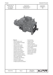
Fig. 1<br />
Fig. 2<br />
USEFUL FORCE<br />
FORZA UTILE<br />
FORCE UTILE<br />
TOTAL FORCE<br />
FORZA TOTALE<br />
FORCE TOTALE<br />
Rotation center<br />
Centro di rotazione<br />
Centre de rotation<br />
Weight Center - Baricentro - Barycentre<br />
TOTAL WEIGH<br />
PESO TOTALE<br />
POIDS TOTALE<br />
ANGLE°<br />
ANGOLO°<br />
GAS SPRING<br />
MOLLA A GAS<br />
RESSORT A’ GAZ<br />
TOTAL WEIGH x a = USEFUL FORCE x b<br />
PESO TOTALE x a = FORZA UTILE x b<br />
POIDS TOTALE x a = FORCE UTILE x b<br />
8<br />
N.B.: The company reserves the right to make changes - N.B.: Con riserva di modifiche - N.B.: Sous réserve de modification
GAS SPRINGS<br />
AISI 316 L
GAS SPRINGS<br />
AISI 316L<br />
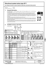
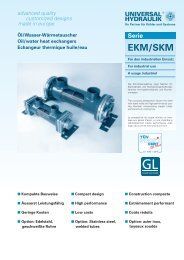
Bore 19 mm <strong>Gas</strong> <strong>Springs</strong><br />
Molle a <strong>Gas</strong> da 19 mm<br />
Ressort à Gaz diam. 19 mm<br />
23,0<br />
EXTENSION<br />
ESTENSIONE<br />
EXTENSION<br />
ø 12,0<br />
6,0<br />
ø 8,0<br />
ø 8,0<br />
STROKE<br />
CORSA<br />
COURSE<br />
TOTAL LENGTH<br />
LUNGHEZZA TOTALE<br />
LONGUEUR TOTALE<br />
ø 19,0 ø 19,0<br />
ø12,0<br />
ø 6,0<br />
ø 8,0<br />
16,0<br />
ø12,0<br />
5,0<br />
STROKE<br />
CORSA<br />
COURSE<br />
TOTAL LENGTH<br />
LUNGHEZZA TOTALE<br />
LONGUEUR TOTALE<br />
8,0<br />
5,0<br />
Standard Strokes<br />
Forces<br />
Corse Standard<br />
Forze<br />
Courses Standard<br />
Forces<br />
Stroke Total Length Extension from to<br />
Corsa Lung. Totale Estension da a<br />
Course Long. Totale Extension de à<br />
mm mm mm N N<br />
60 231 193 500 800<br />
80 271 233 500 800<br />
100 311 273 500 800<br />
120 351 313 500 800<br />
140 391 353 500 800<br />
160 431 393 100 800<br />
180 471 433 100 800<br />
200 511 473 100 800<br />
220 551 513 100 800<br />
250 611 573 100 800<br />
10<br />
N.B.: The company reserves the right to make changes - N.B.: Con riserva di modifiche - N.B.: Sous réserve de modification
AISI 316L<br />
GAS SPRINGS<br />
AISI L GAS SPRINGS EXT. BORE 19 mm<br />
MOLLE A GAS IN AISI 316L DIAM. EST. 19 mm<br />
RESSORTS’ A’ GAZ EN AISI 316L DIAM. EXT. 19 mm<br />
STROKE<br />
CORSA<br />
COURSE<br />
mm<br />
TOTAL LENGHT<br />
LUNG. TOTALE<br />
LONG. TOTAL<br />
mm<br />
FORCE<br />
FORZA<br />
FORCE<br />
N<br />
CODE<br />
CODICE<br />
CODE<br />
STROKE<br />
CORSA<br />
COURSE<br />
mm<br />
TOTAL LENGHT<br />
LUNG TOTALE<br />
LONG. TOTAL<br />
mm<br />
FORCE<br />
FORZA<br />
FORCE<br />
N<br />
CODICE<br />
CODICE<br />
CODE<br />
60 231 500 MG19060500 200 511 100 MG19200100<br />
231 600 MG19060600 511 150 MG19200150<br />
231 700 MG19060700 511 200 MG19200200<br />
231 800 MG19060800 511 250 MG19200250<br />
80 271 500 MG19080500 511 300 MG19200300<br />
271 600 MG19080600 511 350 MG19200350<br />
271 700 MG19080700 511 400 MG19200400<br />
271 800 MG19080800 511 500 MG19200500<br />
100 311 500 MG19100500 511 600 MG19200600<br />
311 600 MG19100600 511 700 MG19200700<br />
311 700 MG19100700 511 800 MG19200800<br />
311 800 MG19100800 220 551 100 MG19220100<br />
120 351 500 MG19120500 551 150 MG19220150<br />
351 600 MG19120600 551 200 MG19220200<br />
351 700 MG19120700 551 250 MG19220250<br />
351 800 MG19120800 551 300 MG19220300<br />
140 391 500 MG19140500 551 350 MG19220350<br />
391 600 MG19140600 551 400 MG19220400<br />
391 700 MG19140700 551 500 MG19220500<br />
391 800 MG19140800 551 600 MG19220600<br />
160 431 100 MG19160100 551 700 MG19220700<br />
431 150 MG19160150 551 800 MG19220800<br />
431 200 MG19160200 250 611 100 MG19250100<br />
431 250 MG19160250 611 150 MG19250150<br />
431 300 MG19160300 611 200 MG19250200<br />
431 350 MG19160350 611 250 MG19250250<br />
431 400 MG19160400 611 300 MG19250300<br />
431 450 MG19160450 611 350 MG19250350<br />
431 500 MG19160500 611 400 MG19250400<br />
431 550 MG19160550 611 500 MG19250500<br />
431 600 MG19160600 611 600 MG19250600<br />
431 650 MG19160650 611 700 MG19250700<br />
431 700 MG19160700 611 800 MG19250800<br />
431 750 MG19160750<br />
431 800 MG19160800<br />
180 471 100 MG19180100<br />
471 150 MG19180150<br />
471 200 MG19180200<br />
471 250 MG19180250<br />
471 300 MG19180300<br />
471 350 MG19180350<br />
471 400 MG19180400<br />
471 500 MG19180500<br />
471 600 MG19180600<br />
471 700 MG19180700<br />
471 800 MG19180800<br />
N.B.: The company reserves the right to make changes - N.B.: Con riserva di modifiche - N.B.: Sous réserve de modification<br />
11
GAS SPRINGS<br />
AISI 316L<br />
Bore 25 mm <strong>Gas</strong> <strong>Springs</strong><br />
Molle a <strong>Gas</strong> da 25 mm<br />
Ressort à Gaz diam. 25 mm<br />
35,0<br />
EXTENSION<br />
ESTENSIONE<br />
EXTENSION<br />
ø 18,0<br />
9,0<br />
ø 10,0<br />
ø 12,0<br />
STROKE<br />
CORSA<br />
COURSE<br />
TOTAL LENGTH<br />
LUNGHEZZA TOTALE<br />
LONGUEUR TOTALE<br />
ø 25,0 ø 25,0<br />
ø 18,0<br />
ø 9,0<br />
ø 10,0<br />
23,0<br />
ø18,0<br />
10,0<br />
STROKE<br />
CORSA<br />
COURSE<br />
TOTAL LENGTH<br />
LUNGHEZZA TOTALE<br />
LONGUEUR TOTALE<br />
9,0<br />
10,0<br />
Standard Strokes<br />
Forces<br />
Corse Standard<br />
Forze<br />
Courses Standard<br />
Forces<br />
Stroke Total Length Extension from to<br />
Corsa Lung. Totale Estension da a<br />
Course Long. Totale Extension de à<br />
mm mm mm N N<br />
100 351 290 500 1000<br />
120 391 330 500 1000<br />
140 431 370 500 1000<br />
160 471 410 250 1000<br />
180 511 450 250 1000<br />
200 551 490 250 1000<br />
220 591 530 250 1000<br />
250 651 590 250 1000<br />
280 711 650 250 1000<br />
300 751 690 250 1000<br />
12<br />
N.B.: The company reserves the right to make changes - N.B.: Con riserva di modifiche - N.B.: Sous réserve de modification
AISI 316L<br />
GAS SPRINGS<br />
AISI L GAS SPRINGS EXT. BORE 25 mm<br />
MOLLE A GAS IN AISI 316L DIAM. EST. 25mm<br />
RESSORTS’ A’ GAZ EN AISI 316L DIAM. EXT. 25 mm<br />
STROKE<br />
CORSA<br />
COURSE<br />
mm<br />
TOTAL LENGHT<br />
LUNG. TOTALE<br />
LONG. TOTAL<br />
mm<br />
FORCE<br />
FORZA<br />
FORCE<br />
N<br />
CODE<br />
CODICE<br />
CODE<br />
STROKE<br />
CORSA<br />
COURSE<br />
mm<br />
TOTAL LENGHT<br />
LUNG TOTALE<br />
LONG. TOTAL<br />
mm<br />
FORCE<br />
FORZA<br />
FORCE<br />
N<br />
CODICE<br />
CODICE<br />
CODE<br />
100 351 500 MG251000500 180 511 500 MG251800500<br />
351 600 MG251000600 511 600 MG251800600<br />
351 700 MG251000700 511 700 MG251800700<br />
351 800 MG251000800 511 800 MG251800800<br />
351 900 MG251000900 511 900 MG251800900<br />
351 1000 MG251001000 511 1000 MG251801000<br />
351 1100 MG251001100 511<br />
351 1200 MG251001200 511<br />
120 391 500 MG251200500 200 551 500 MG252000500<br />
391 600 MG251200600 551 600 MG252000600<br />
391 700 MG251200700 551 700 MG252000700<br />
391 800 MG251200800 551 800 MG252000800<br />
391 900 MG251200900 551 900 MG252000900<br />
391 1000 MG251201000 551 1000 MG252001000<br />
391 1100 MG251201100<br />
391 1200 MG251201200<br />
140 431 500 MG251400500 220 591 500 MG252200500<br />
431 600 MG251400600 591 600 MG252200600<br />
431 700 MG251400700 591 700 MG252200700<br />
431 800 MG251400800 591 800 MG252200800<br />
431 900 MG251400900 591 900 MG252200900<br />
431 1000 MG251401000 591 1000 MG252201000<br />
160 471 500 MG251600500 250 651 500 MG252500500<br />
471 600 MG251600600 651 600 MG252500600<br />
471 700 MG251600700 651 700 MG252500700<br />
471 800 MG251600800 651 800 MG252500800<br />
471 900 MG251600900 651 900 MG252500900<br />
471 1000 MG251601000 651 1000 MG252501000<br />
N.B.: The company reserves the right to make changes - N.B.: Con riserva di modifiche - N.B.: Sous réserve de modification<br />
13
GAS SPRINGS<br />
AISI 316L<br />
Bore 30 mm <strong>Gas</strong> <strong>Springs</strong><br />
Molle a <strong>Gas</strong> da 30 mm<br />
Ressort à Gaz diam. 30 mm<br />
35,0<br />
EXTENSION<br />
ESTENSIONE<br />
EXTENSION<br />
ø 18,0<br />
9,0<br />
ø 10,0<br />
ø 14,0<br />
STROKE<br />
CORSA<br />
COURSE<br />
TOTAL LENGTH<br />
LUNGHEZZA TOTALE<br />
LONGUEUR TOTALE<br />
ø 30,0 ø 30,0<br />
ø18,0<br />
23,0<br />
ø 9,0<br />
ø 10,0<br />
ø18,0<br />
10,0<br />
STROKE<br />
CORSA<br />
COURSE<br />
TOTAL LENGTH<br />
LUNGHEZZA TOTALE<br />
LONGUEUR TOTALE<br />
9,0<br />
10,0<br />
Standard Strokes<br />
Forces<br />
Corse Standard<br />
Forze<br />
Courses Standard<br />
Forces<br />
Stroke Total Length Extension from to<br />
Corsa Lung. Totale Estension da a<br />
Course Long. Totale Extension de à<br />
mm mm mm N N<br />
100 357 299 1000 2000<br />
120 397 339 1000 2000<br />
140 437 379 1000 2000<br />
160 477 419 1000 2000<br />
180 517 459 1000 2000<br />
200 557 499 1000 2000<br />
220 597 539 1000 2000<br />
250 657 599 1000 2000<br />
14<br />
N.B.: The company reserves the right to make changes - N.B.: Con riserva di modifiche - N.B.: Sous réserve de modification
AISI 316L<br />
GAS SPRINGS<br />
AISI L GAS SPRINGS EXT. BORE 30 mm<br />
MOLLE A GAS IN AISI 316L DIAM. EST. 30 mm<br />
RESSORTS’ A’ GAZ EN AISI 316L DIAM. EXT. 30 mm<br />
STROKE<br />
CORSA<br />
COURSE<br />
mm<br />
TOTAL LENGHT<br />
LUNG. TOTALE<br />
LONG. TOTAL<br />
mm<br />
FORCE<br />
FORZA<br />
FORCE<br />
N<br />
CODE<br />
CODICE<br />
CODE<br />
STROKE<br />
CORSA<br />
COURSE<br />
mm<br />
TOTAL LENGHT<br />
LUNG TOTALE<br />
LONG. TOTAL<br />
mm<br />
FORCE<br />
FORZA<br />
FORCE<br />
N<br />
CODICE<br />
CODICE<br />
CODE<br />
100 357 1000 MG301001000 180 517 1000 MG301801000<br />
357 1200 MG301001200 517 1200 MG301801200<br />
357 1400 MG301001400 517 1400 MG301801400<br />
357 1600 MG301001600 517 1600 MG301801600<br />
357 1800 MG301001800 517 1800 MG301801800<br />
357 2000 MG301002000 517 2000 MG301802000<br />
120 397 1000 MG301201000 200 557 1000 MG302001000<br />
391 1200 MG301201200 557 1200 MG302001200<br />
391 1400 MG301201400 557 1400 MG302001400<br />
391 1600 MG301201600 557 1600 MG302001600<br />
391 1800 MG301201800 557 1800 MG302001800<br />
391 2000 MG301202000 557 2000 MG302002000<br />
140 437 1000 MG301401000 220 597 1000 MG302201000<br />
437 1200 MG301401200 597 1200 MG302201200<br />
437 1400 MG301401400 597 1400 MG302201400<br />
437 1600 MG301401600 597 1600 MG302201600<br />
437 1800 MG301401800 597 1800 MG302201800<br />
437 2000 MG301402000 597 2000 MG302202000<br />
160 477 1000 MG301601000 250 657 1000 MG302501000<br />
477 1200 MG301601200 657 1200 MG302501200<br />
477 1400 MG301601400 657 1400 MG302501400<br />
477 1600 MG301601600 657 1600 MG302501600<br />
477 1800 MG301601800 657 1800 MG302501800<br />
477 2000 MG301602000 657 2000 MG302502000<br />
N.B.: The company reserves the right to make changes - N.B.: Con riserva di modifiche - N.B.: Sous réserve de modification<br />
15
GAS SPRINGS<br />
AISI 316L<br />
Bore 40 mm <strong>Gas</strong> <strong>Springs</strong><br />
Molle a <strong>Gas</strong> da 40 mm<br />
Ressort à Gaz diam. 40 mm<br />
EXTENSION<br />
ESTENSIONE<br />
EXTENSION<br />
STROKE<br />
CORSA<br />
COURSE<br />
TOTAL LENGTH<br />
LUNGHEZZA TOTALE<br />
LONGUEUR TOTALE<br />
STROKE<br />
CORSA<br />
COURSE<br />
TOTAL LENGTH<br />
LUNGHEZZA TOTALE<br />
LONGUEUR TOTALE<br />
Standard Strokes<br />
Forces<br />
Corse Standard<br />
Forze<br />
Courses Standard<br />
Forces<br />
Stroke Total Length Extension from to<br />
Corsa Lung. Totale Estension da a<br />
Course Long. Totale Extension de à<br />
mm mm mm N N<br />
100 374 309 1000 2000<br />
140 454 389 1000 2000<br />
180 534 469 1000 2000<br />
200 574 509 1000 2000<br />
250 674 609 1000 2000<br />
300 774 709 1000 2000<br />
400 974 909 1000 2000<br />
500 1174 1109 1000 2000<br />
16<br />
N.B.: The company reserves the right to make changes - N.B.: Con riserva di modifiche - N.B.: Sous réserve de modification
AISI 316L<br />
GAS SPRINGS<br />
AISI L GAS SPRINGS EXT. BORE 40 mm<br />
MOLLE A GAS IN AISI 316L DIAM. EST. 40mm<br />
RESSORTS’ A’ GAZ EN AISI 316L DIAM. EXT. 40mm<br />
STROKE<br />
CORSA<br />
COURSE<br />
mm<br />
TOTAL LENGHT<br />
LUNG. TOTALE<br />
LONG. TOTAL<br />
mm<br />
FORCE<br />
FORZA<br />
FORCE<br />
N<br />
CODE<br />
CODICE<br />
CODE<br />
STROKE<br />
CORSA<br />
COURSE<br />
mm<br />
TOTAL LENGHT<br />
LUNG TOTALE<br />
LONG. TOTAL<br />
mm<br />
FORCE<br />
FORZA<br />
FORCE<br />
N<br />
CODICE<br />
CODICE<br />
CODE<br />
100 374 1000 MG401001000 250 674 1000 MG402501000<br />
374 1400 MG401001400 674 1400 MG402501400<br />
374 1800 MG401001800 674 1800 MG402501800<br />
374 2200 MG401002200 674 2200 MG402502200<br />
374 2500 MG401002500 674 2500 MG402502500<br />
374 3000 MG401003000 674 3000 MG402503000<br />
140 454 1000 MG401401000 300 774 1000 MG403001000<br />
454 1400 MG401401400 774 1400 MG403001400<br />
454 1800 MG401401800 774 1800 MG403001800<br />
454 2200 MG401402200 774 2200 MG403002200<br />
454 2500 MG401402500 774 2500 MG403002500<br />
454 3000 MG401403000 774 3000 MG403003000<br />
180 534 1000 MG401801000 400 974 1000 MG404001000<br />
534 1400 MG401801400 974 1400 MG404001400<br />
534 1800 MG401801800 974 1800 MG404001800<br />
534 2200 MG401802200 974 2200 MG404002200<br />
534 2500 MG401802500 974 2500 MG404002500<br />
534 3000 MG401803000 974 3000 MG404003000<br />
200 574 1000 MG402001000 500 1174 1000 MG405001000<br />
574 1400 MG402001400 1174 1400 MG405001400<br />
574 1800 MG402001800 1174 1800 MG405001800<br />
574 2200 MG402002200 1174 2200 MG405002200<br />
574 2500 MG402002500 1174 2500 MG405002500<br />
574 3000 MG402003000 1174 3000 MG405003000<br />
N.B.: The company reserves the right to make changes - N.B.: Con riserva di modifiche - N.B.: Sous réserve de modification<br />
17
GAS SPRINGS<br />
AISI 316L<br />
<strong>Gas</strong> <strong>Springs</strong> - General Dimensions<br />
Molle a <strong>Gas</strong> - Dimensionamento Generale<br />
Ressort à Gaz - Dimensions Générales<br />
F<br />
EXTENSION (see specific data-sheet)<br />
ESTENSIONE (vedere foglio specifico)<br />
EXTENSION (voir doc. spécifique)<br />
D<br />
ø A<br />
D<br />
ø B<br />
ø E<br />
ø C<br />
ø E<br />
STROKE<br />
CORSA<br />
COURSE<br />
TOTAL LENGTH (see specific data-sheet)<br />
LUNGHEZZA TOTALE (vedere foglio specifico)<br />
LONGUEUR TOTALE (voir doc. spécifique)<br />
G<br />
ø C<br />
ø A<br />
ø C<br />
H<br />
STROKE<br />
CORSA<br />
COURSE<br />
TOTAL LENGTH (see specific data-sheet)<br />
LUNGHEZZA TOTALE (vedere foglio specifico)<br />
LONGUEUR TOTALE (voir doc. spécifique)<br />
D<br />
H<br />
A B C D E F G H<br />
19 8,0 12,0 6,0 8,0 23,0 16,0 5,0<br />
25 12,0 18,0 9,0 10,0 35,0 23,0 10,0<br />
30 14,0 18,0 9,0 10,0 35,0 23,0 10,0<br />
40 20,0 20,0 10,0 10,0 42,0 23,0 14,0<br />
18<br />
N.B.: The company reserves the right to make changes - N.B.: Con riserva di modifiche - N.B.: Sous réserve de modification
GAS SPRINGS<br />
ALUMINIUM
GAS SPRINGS<br />
ALUMINIUM<br />
Bore 19 mm Aluminium <strong>Gas</strong> <strong>Springs</strong><br />
Molle a <strong>Gas</strong> da 19 mm in Alluminio<br />
Ressort à Gaz diam. 19 mm en Aluminium<br />
23.0<br />
EXTENSION<br />
ESTENSIONE<br />
EXTENSION<br />
6.0<br />
Ø8.0<br />
Ø19.0<br />
6.0<br />
Ø12.0<br />
Ø12.0<br />
Ø8.0<br />
STROKE<br />
CORSA<br />
COURSE<br />
TOTAL LENGTH<br />
LUNGHEZZA TOTALE<br />
LONGUEUR TOTALE<br />
Ø8.0<br />
16.0<br />
AISI 316 L<br />
ACCIAIO INOX<br />
ALLUMINIUM<br />
ALLUMINIO<br />
Ø19.0<br />
5.0<br />
Ø12.0<br />
STROKE<br />
CORSA<br />
COURSE<br />
TOTAL LENGTH<br />
LUNGHEZZA TOTALE<br />
LONGUEUR TOTALE<br />
8.0<br />
5.0<br />
Standard Strokes<br />
Forces<br />
Corse Standard<br />
Forze<br />
Courses Standard<br />
Forces<br />
Stroke Total Length Extension from to<br />
Corsa Lung. Totale Estension da a<br />
Course Long. Totale Extension de à<br />
mm mm mm N N<br />
60 231 193 500 800<br />
80 271 233 500 800<br />
100 311 273 500 800<br />
120 351 313 500 800<br />
140 391 353 500 800<br />
160 431 393 100 800<br />
180 471 433 100 800<br />
200 511 473 100 800<br />
220 551 513 100 800<br />
250 611 573 100 800<br />
20<br />
N.B.: The company reserves the right to make changes - N.B.: Con riserva di modifiche - N.B.: Sous réserve de modification
ALUMINIUM<br />
GAS SPRINGS<br />
ALUMINIUM GAS SPRINGS EXT. BORE 19 mm<br />
MOLLE A GAS IN ALLUMINIO DIAM. EST. 19 mm<br />
RESSORTS’ A’ GAZ EN ALUMINIUM DIAM. EXT. 19 mm<br />
STROKE<br />
CORSA<br />
COURSE<br />
mm<br />
TOTAL LENGHT<br />
LUNG. TOTALE<br />
LONG. TOTAL<br />
mm<br />
FORCE<br />
FORZA<br />
FORCE<br />
N<br />
CODE<br />
CODICE<br />
CODE<br />
STROKE<br />
CORSA<br />
COURSE<br />
mm<br />
TOTAL LENGHT<br />
LUNG TOTALE<br />
LONG. TOTAL<br />
mm<br />
FORCE<br />
FORZA<br />
FORCE<br />
N<br />
CODICE<br />
CODICE<br />
CODE<br />
60 231 500 MGA19060500 200 511 100 MGA19200100<br />
231 600 MGA19060600 511 150 MGA19200150<br />
231 700 MGA19060700 511 200 MGA19200200<br />
231 800 MGA19060800 511 250 MGA19200250<br />
80 271 500 MGA19080500 511 300 MGA19200300<br />
271 600 MGA19080600 511 350 MGA19200350<br />
271 700 MGA19080700 511 400 MGA19200400<br />
271 800 MGA19080800 511 500 MGA19200500<br />
100 311 500 MGA19100500 511 600 MGA19200600<br />
311 600 MGA19100600 511 700 MGA19200700<br />
311 700 MGA19100700 511 800 MGA19200800<br />
311 800 MGA19100800 220 551 100 MGA19220100<br />
120 351 500 MGA19120500 551 150 MGA19220150<br />
351 600 MGA19120600 551 200 MGA19220200<br />
351 700 MGA19120700 551 250 MGA19220250<br />
351 800 MGA19120800 551 300 MGA19220300<br />
140 391 500 MGA19140500 551 350 MGA19220350<br />
391 600 MGA19140600 551 400 MGA19220400<br />
391 700 MGA19140700 551 500 MGA19220500<br />
391 800 MGA19140800 551 600 MGA19220600<br />
160 431 100 MGA19160100 551 700 MGA19220700<br />
431 150 MGA19160150 551 800 MGA19220800<br />
431 200 MGA19160200 250 611 100 MGA19250100<br />
431 250 MGA19160250 611 150 MGA19250150<br />
431 300 MGA19160300 611 200 MGA19250200<br />
431 350 MGA19160350 611 250 MGA19250250<br />
431 400 MGA19160400 611 300 MGA19250300<br />
431 450 MGA19160450 611 350 MGA19250350<br />
431 500 MGA19160500 611 400 MGA19250400<br />
431 550 MGA19160550 611 500 MGA19250500<br />
431 600 MGA19160600 611 600 MGA19250600<br />
431 650 MGA19160650 611 700 MGA19250700<br />
431 700 MGA19160700 611 800 MGA19250800<br />
431 750 MGA19160750<br />
431 800 MGA19160800<br />
180 471 100 MGA19180100<br />
471 150 MGA19180150<br />
471 200 MGA19180200<br />
471 250 MGA19180250<br />
471 300 MGA19180300<br />
471 350 MGA19180350<br />
471 400 MGA19180400<br />
471 500 MGA19180500<br />
471 600 MGA19180600<br />
471 700 MGA19180700<br />
471 800 MGA19180800<br />
N.B.: The company reserves the right to make changes - N.B.: Con riserva di modifiche - N.B.: Sous réserve de modification 21
GAS SPRINGS<br />
ALUMINIUM<br />
Bore 25 mm Aluminium <strong>Gas</strong> <strong>Springs</strong><br />
Molle a <strong>Gas</strong> da 25 mm in Alluminio<br />
Ressort à Gaz diam. 25 mm en Aluminium<br />
35.0<br />
EXTENSION<br />
ESTENSIONE<br />
EXTENSION<br />
9.0<br />
Ø12.0<br />
Ø25.0<br />
9.0<br />
Ø18.0<br />
Ø10.0<br />
STROKE<br />
CORSA<br />
COURSE<br />
TOTAL LENGTH<br />
LUNGHEZZA TOTALE<br />
LONGUEUR TOTALE<br />
Ø10.0<br />
23.0<br />
Ø18.0<br />
AISI 316 L<br />
ACCIAIO INOX<br />
ALLUMINIUM<br />
ALLUMINIO<br />
Ø25.0<br />
10.0<br />
Ø18.0<br />
STROKE<br />
CORSA<br />
COURSE<br />
TOTAL LENGTH<br />
LUNGHEZZA TOTALE<br />
LONGUEUR TOTALE<br />
9.0<br />
10.0<br />
Standard Strokes<br />
Forces<br />
Corse Standard<br />
Forze<br />
Courses Standard<br />
Forces<br />
Stroke Total Length Extension from to<br />
Corsa Lung. Totale Estension da a<br />
Course Long. Totale Extension de à<br />
mm mm mm N N<br />
100 351 290 500 1000<br />
120 391 330 500 1000<br />
140 431 370 500 1000<br />
160 471 410 250 1000<br />
180 511 450 250 1000<br />
200 551 490 250 1000<br />
220 591 530 250 1000<br />
250 651 590 250 1000<br />
280 711 650 250 1000<br />
300 751 690 250 1000<br />
22<br />
N.B.: The company reserves the right to make changes - N.B.: Con riserva di modifiche - N.B.: Sous réserve de modification
ALUMINIUM<br />
GAS SPRINGS<br />
ALUMINIUM GAS SPRINGS EXT. BORE 25 mm<br />
MOLLE A GAS IN ALLUMINIO DIAM. EST. 25mm<br />
RESSORTS’ A’ GAZ EN ALUMINIUM DIAM. EXT. 25 mm<br />
STROKE<br />
CORSA<br />
COURSE<br />
mm<br />
TOTAL LENGHT<br />
LUNG. TOTALE<br />
LONG. TOTAL<br />
mm<br />
FORCE<br />
FORZA<br />
FORCE<br />
N<br />
CODE<br />
CODICE<br />
CODE<br />
STROKE<br />
CORSA<br />
COURSE<br />
mm<br />
TOTAL LENGHT<br />
LUNG TOTALE<br />
LONG. TOTAL<br />
mm<br />
FORCE<br />
FORZA<br />
FORCE<br />
N<br />
CODICE<br />
CODICE<br />
CODE<br />
100 351 500 MGA251000500 180 511 500 MGA251800500<br />
351 600 MGA251000600 511 600 MGA251800600<br />
351 700 MGA251000700 511 700 MGA251800700<br />
351 800 MGA251000800 511 800 MGA251800800<br />
351 900 MGA251000900 511 900 MGA251800900<br />
351 1000 MGA251001000 511 1000 MGA251801000<br />
351 1100 MGA251001100 511<br />
351 1200 MGA251001200 511<br />
120 391 500 MGA251200500 200 551 500 MGA252000500<br />
391 600 MGA251200600 551 600 MGA252000600<br />
391 700 MGA251200700 551 700 MGA252000700<br />
391 800 MGA251200800 551 800 MGA252000800<br />
391 900 MGA251200900 551 900 MGA252000900<br />
391 1000 MGA251201000 551 1000 MGA252001000<br />
391 1100 MGA251201100<br />
391 1200 MGA251201200<br />
140 431 500 MGA251400500 220 591 500 MGA252200500<br />
431 600 MGA251400600 591 600 MGA252200600<br />
431 700 MGA251400700 591 700 MGA252200700<br />
431 800 MGA251400800 591 800 MGA252200800<br />
431 900 MGA251400900 591 900 MGA252200900<br />
431 1000 MGA251401000 591 1000 MGA252201000<br />
160 471 500 MGA251600500 250 651 500 MGA252500500<br />
471 600 MGA251600600 651 600 MGA252500600<br />
471 700 MGA251600700 651 700 MGA252500700<br />
471 800 MGA251600800 651 800 MGA252500800<br />
471 900 MGA251600900 651 900 MGA252500900<br />
471 1000 MGA251601000 651 1000 MGA252501000<br />
N.B.: The company reserves the right to make changes - N.B.: Con riserva di modifiche - N.B.: Sous réserve de modification 23
GAS SPRINGS<br />
ALUMINIUM<br />
<strong>Gas</strong> <strong>Springs</strong> - General Dimensions<br />
Molle a <strong>Gas</strong> - Dimensionamento Generale<br />
Ressort à Gaz - Dimensions Générales<br />
F<br />
EXTENSION (see specific data-sheet)<br />
ESTENSIONE (vedere foglio specifico)<br />
EXTENSION (voir doc. spécifique)<br />
D<br />
ø A<br />
D<br />
ø B<br />
ø E<br />
ø C<br />
ø E<br />
STROKE<br />
CORSA<br />
COURSE<br />
TOTAL LENGTH (see specific data-sheet)<br />
LUNGHEZZA TOTALE (vedere foglio specifico)<br />
LONGUEUR TOTALE (voir doc. spécifique)<br />
G<br />
ø C<br />
ø A<br />
ø C<br />
H<br />
STROKE<br />
CORSA<br />
COURSE<br />
TOTAL LENGTH (see specific data-sheet)<br />
LUNGHEZZA TOTALE (vedere foglio specifico)<br />
LONGUEUR TOTALE (voir doc. spécifique)<br />
D<br />
H<br />
A B C D E F G H<br />
19 8,0 12,0 6,0 8,0 23,0 16,0 5,0<br />
25 12,0 18,0 9,0 10,0 35,0 23,0 10,0<br />
24<br />
N.B.: The company reserves the right to make changes - N.B.: Con riserva di modifiche - N.B.: Sous réserve de modification
GAS SPRINGS<br />
FIXATION DEVICES IN AISI 316 L FISSAGGI IN AISI 316 L FIXATIONS EN AISI 316 L<br />
26<br />
5<br />
42<br />
26<br />
11<br />
42<br />
Ø8<br />
21 5<br />
12.5<br />
12.5<br />
7 28 7<br />
7<br />
22<br />
19<br />
Ø6<br />
CODE<br />
LP/04476 =<br />
U Type for MG 19 Not Oscillating Heads<br />
Tipo ad U per MG 19 Teste Non Oscillanti<br />
Type à U pour MG 19 Tetes pas Rotulées<br />
Ø8<br />
CODE<br />
LP/04476.01 =<br />
U Type for MG 19 Oscillating Heads<br />
Tipo ad U per MG 19 Teste Oscillanti<br />
Type à U pour MG 19 Tetes Rotulées<br />
Ø6<br />
56<br />
11 17 17 11<br />
2.5<br />
27.5<br />
15<br />
11<br />
17<br />
56<br />
17<br />
11<br />
2.5<br />
15<br />
33.5<br />
30<br />
30<br />
Ø14<br />
Ø6<br />
5<br />
CODE<br />
LP/04475 =<br />
Flat Type for MG 19 Not Oscillating Heads<br />
Tipo Piano per MG 19 Teste Non Oscillanti<br />
Type Plat pour MG 19 Tetes pas Rotulées<br />
CODE<br />
LP/04475.01 =<br />
Flat Type for MG 19 Oscillating Heads<br />
Tipo Piano per MG 19 Teste Oscillanti<br />
Type Plat pour MG 19 Tetes Rotulées<br />
45<br />
2.5<br />
25<br />
45<br />
6<br />
25<br />
5<br />
Ø8<br />
N.2 FORI Ø5.5<br />
12<br />
13<br />
53<br />
12.5<br />
26.5<br />
26.5<br />
N.2 FORI Ø5.5<br />
13<br />
56<br />
12.5<br />
7.5<br />
30<br />
7.5<br />
7.5 30<br />
7.5<br />
CODE<br />
LP/04482 =<br />
L Type for MG 19 Not Oscillating Heads<br />
Tipo ad L per MG 19 Teste Non Oscillanti<br />
Type a L pour MG 19 Tetes Pas Rotulées<br />
CODE<br />
LP/04482.01 =<br />
L Type for MG 19 Oscillating Heads<br />
Tipo ad L per MG 19 Teste Oscillanti<br />
Type à L pour MG 19 Tetes Rotulées<br />
N.B.: The company reserves the right to make changes - N.B.: Con riserva di modifiche - N.B.: Sous réserve de modification 25
GAS SPRINGS<br />
FIXATION DEVICES IN AISI 316 L FISSAGGI IN AISI 316 L FIXATIONS EN AISI 316 L<br />
Ø10<br />
10<br />
37<br />
25<br />
14<br />
10<br />
30.5<br />
15<br />
32.5<br />
66.5<br />
Ø10<br />
80<br />
80<br />
15<br />
30.5<br />
32.5<br />
10<br />
20 20 20<br />
10<br />
10 14 32<br />
14<br />
10<br />
CODE<br />
LP/04381 =<br />
L Type for MG 25/30/40 Hall Version<br />
Tipo ad L per MG 25/30/40 Tutte le Versioni<br />
Type à L pour MG 25/30/40 Toutes les Versions<br />
CODE<br />
LP/04382 =<br />
U Large Type for MG 25/30/40 Hall Versions<br />
Tipo ad U Grande per MG 25/30/40 Tutte le Versioni<br />
Type à U Large pour MG 25/30/40 Toutes les Versions<br />
37<br />
25<br />
18<br />
12.5<br />
34.5<br />
80<br />
Ø10<br />
15<br />
32.5<br />
15<br />
Ø8<br />
Ø15<br />
Ø8<br />
Ø5.2<br />
30.5<br />
30.5<br />
80<br />
5.5<br />
63<br />
10 20 20 20 10<br />
32.5<br />
10 14 32 14 10<br />
CODE<br />
LP/04397 =<br />
L Type for MG 19 Oscillating Heads<br />
Tipo ad L per MG 19 Teste Oscillanti<br />
Type à L pour MG 19 Tetes Rotulées<br />
CODE U Large Type for MG 19 Not Oscillating Heads<br />
LP/04398 = Tipo ad U Grande per MG 19 Teste Non Oscillanti<br />
Type à U Large pour MG 19 Tetes pas Rotulées<br />
37<br />
25<br />
18<br />
80<br />
15<br />
Ø10<br />
Ø14<br />
Ø6<br />
30.5<br />
30.5<br />
Ø11,2<br />
8.5<br />
80<br />
63<br />
10 20 20 20 10<br />
32.5<br />
15<br />
Ø6,0<br />
32.5<br />
10<br />
14<br />
32<br />
14<br />
10<br />
CODE<br />
LP/04397.01 =<br />
L Type for MG 19 Oscillating Heads<br />
Tipo ad L per MG 19 Teste Oscillanti<br />
Type à L pour MG 19 Tetes Rotulées<br />
CODE<br />
LP/04398.01 =<br />
U Large Type for MG 19 Oscillating Heads<br />
Tipo ad U Grande per MG 19 Teste Oscillanti<br />
Type à U Large pour MG 19 Tetes Rotulées<br />
26<br />
N.B.: The company reserves the right to make changes - N.B.: Con riserva di modifiche - N.B.: Sous réserve de modification
GAS SPRINGS<br />
14<br />
12<br />
5<br />
+0.10<br />
M6<br />
0<br />
6<br />
6 8 15<br />
Ø12<br />
5<br />
Ø8<br />
+0.10<br />
0<br />
4 8 8<br />
M10<br />
4<br />
Ø8<br />
Ø12<br />
2<br />
29<br />
9<br />
31<br />
19<br />
9 12 23<br />
10<br />
Ø18<br />
10<br />
+0.10<br />
0<br />
FIXATION DEVICES IN AISI 316 L FISSAGGI IN AISI 316 L FIXATIONS EN AISI 316 L<br />
CODE<br />
05746 =<br />
<strong>Gas</strong> Spring Ø19 Male Rod Eye<br />
Molle a <strong>Gas</strong> Ø19 Forcella Maschio Stelo<br />
Ressort à Gaz Ø19 Chape de Tige Male<br />
CODE<br />
05746 =<br />
<strong>Gas</strong> Spring Ø19 Male End Eye<br />
Molle a <strong>Gas</strong> Ø19 Forcella Maschio Post.<br />
Ressort à Gaz Ø19 Chape Arrière Male<br />
4 9<br />
0<br />
Ø10 +0.10<br />
M10<br />
M14x1,5<br />
4<br />
23<br />
Ø10<br />
Ø18<br />
44<br />
20<br />
52<br />
CODE<br />
05750 =<br />
<strong>Gas</strong> Spring Ø25/30/40 Male Rod Eye<br />
Molle a <strong>Gas</strong> Ø25/30/40 Forcella Maschio Stelo<br />
Ressort à Gaz Ø25/30/40 Chape de Tige Male<br />
CODE<br />
05749 =<br />
<strong>Gas</strong> Spring Ø25/30/40 Male End Eye<br />
Molle a <strong>Gas</strong> Ø25/30/40 Forcella Maschio Post.<br />
Ressort à Gaz Ø25/30/40 Chape Arrière Male<br />
N.B.: The company reserves the right to make changes - N.B.: Con riserva di modifiche - N.B.: Sous réserve de modification 27
GAS SPRINGS<br />
AISI 316 L Spinning Heads<br />
Teste a snodo in AISI 316 L<br />
Chapes Rotulèes en AISI 316 L<br />
B<br />
ØD1<br />
B<br />
ØD1<br />
M<br />
M<br />
a∞<br />
E<br />
GL<br />
F<br />
L<br />
Ø0<br />
ØA<br />
ØD2<br />
a∞<br />
GL<br />
F<br />
L<br />
Ø0<br />
ØA<br />
ØD2<br />
G<br />
SW<br />
K<br />
G<br />
<strong>Gas</strong> Spring Bore 19: Code 50572<br />
<strong>Gas</strong> Spring Bore 25/30/40: Code 51313<br />
<strong>Gas</strong> Spring Bore 19:<br />
<strong>Gas</strong> Spring Bore 25/30/40:<br />
Code LP/04302<br />
Code LP/04314<br />
a° ØA B D1 D2 E F G GL K ØO<br />
ø19 13° 12,70 9 20 6 5,0 30 M 6 x 1 12 13 8,9<br />
ø25 13° 19,05 14 28 10 6,5 43 M 10 x 1,5 20 19 12,9<br />
ø30 13° 19,05 14 28 10 6,5 43 M 10 x 1,5 20 19 12,9<br />
ø40 13° 19,05 14 28 10 6,5 43 M 10 x 1,5 20 19 12,9<br />
Accessories for <strong>Gas</strong> <strong>Springs</strong> All Type<br />
Accessori per tutti i tipi di Molle a <strong>Gas</strong><br />
Accessoires pour tous types de Ressort à Gaz<br />
Code<br />
Special valve for charge and set-up of <strong>Gas</strong> Spring<br />
Valvola speciale per la ricarica e la regolazione delle molle a <strong>Gas</strong><br />
Valve special pour recharge et mise à point des Resorts à Gaz<br />
LP/04306<br />
Pressure Regulator I.P 200 Bar - O.P. 100 Bar<br />
Regolatore di pressione P.I. 200 Bar - P.U. 100 Bar<br />
Régulateur de Pression P.I. 200 Bar - P.S.100 Bar<br />
51685<br />
Connecting Flexible Pipe<br />
Tubo Flessibile di Collegamento<br />
Tube Flexible de connection<br />
51526<br />
28<br />
N.B.: The company reserves the right to make changes - N.B.: Con riserva di modifiche - N.B.: Sous réserve de modification
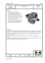
GAS SPRINGS<br />
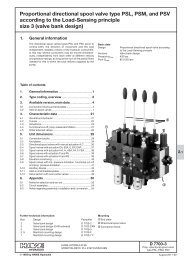
Diagramma Forze/Pressioni<br />
N<br />
Pressione di Carica<br />
3200<br />
10 20 30 40 50 60 70 80 90 100 110 120 130 140 150 160 170 180 190 200 Bar<br />
3100<br />
3000<br />
2900<br />
2800<br />
2700<br />
2600<br />
2500<br />
2400<br />
2300<br />
2200<br />
2100<br />
2000<br />
1900<br />
1800<br />
1700<br />
1600<br />
1500<br />
1400<br />
1300<br />
1200<br />
1100<br />
1000<br />
900<br />
800<br />
700<br />
600<br />
500<br />
400<br />
300<br />
200<br />
100<br />
10 20 30 40 50 60 70 80 90 100 110 120 130 140 150 160 170 180 190 200 Bar<br />
Diam 19<br />
Diam 25<br />
Diam 30<br />
Diam 40<br />
1 Bar = 5 N<br />
1 Bar = 11,3 N<br />
1 Bar = 15,4 N<br />
1 Bar = 31,4 N<br />
N.B.: The company reserves the right to make changes - N.B.: Con riserva di modifiche - N.B.: Sous réserve de modification<br />
29
PRESSMAIR srl<br />
INDUSTRIAL PNEUMATIC COMPONENTS<br />
APPARECCHIATURE PNEUMATICHE INDUSTRIALI<br />
44045 Renazzo di Cento (Ferrara) ITALY - Via Pasquino, 29/a<br />
PH. ++39.051.900122 - Fax ++39.051.909635<br />
www.pressmair.com e-mail: pressmair@tiscali.it