Sicherheitshinweise - lamtec
Sicherheitshinweise - lamtec
Sicherheitshinweise - lamtec

Create successful ePaper yourself
Turn your PDF publications into a flip-book with our unique Google optimized e-Paper software.
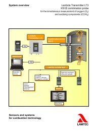
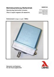
Elektrischer Anschluss Electrical Connection Raccordement électrique<br />
Adjusting of an AC Engine Regulation with 4 - 20 mA<br />
Input/Output Signal AB076<br />
The motor is pre-adjusted at works The following adjustment<br />
instructions have observed ONLY when exchanging the print<br />
board. The respective equipment of the drive is to be considered.:<br />
1. Connect the board to mains, terminal 8 masse, terminal 9 phase and<br />
terminal 10 protective conductor.<br />
2. Apply to terminals 12 and 13 (control input) 4 mA<br />
3. Move the motor to end position 0°, until the mechanic limit switch<br />
is operated. ATTENTION: there is voltage!! at connection terminals<br />
as well as on the reserve side of the board !<br />
4. Turn the shaft of the potentiometer slowly until both signal lamps<br />
are switched off.<br />
5. Fit the gear of the potentiometer to gear of the motor shaft.<br />
6. Apply 20 mA to control input = terminals 12 and 13.<br />
7. Move the motor to end position 90° until the mechanic limit switch<br />
is operated.<br />
8. Turn potentiometer PT 2 (next to transformer) until no signal lamps<br />
is on any more.<br />
9. Then apply 4 mA control voltage and let the motor go to LOW end<br />
position. In this position both signal lamps have to be off. Otherwise<br />
balance adjustment by potentiometer PT 5.<br />
10. Connect a measuring instrument to terminals 11 and 13 (output). In<br />
end position LOW 0° the measure instrument has to show 4 mA.<br />
Otherwise balance adjustment by potentiometer PT 11<br />
11. Move motor to end position HIGH 90° the measuring instrument<br />
has to show 20 mA. Otherwise balance adjustment by potentiometer<br />
PT 9.<br />
Kap. 4