Z140 - HEB Hydraulik - Elementebau GmbH
Z140 - HEB Hydraulik - Elementebau GmbH
Z140 - HEB Hydraulik - Elementebau GmbH

Create successful ePaper yourself
Turn your PDF publications into a flip-book with our unique Google optimized e-Paper software.
<strong>Z140</strong>-10-2011<br />
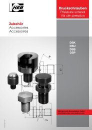
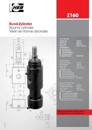
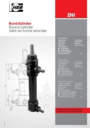
Rund-Zylinder<br />
Round cylinder<br />
Vérin en forme arrondie<br />
<strong>Z140</strong><br />
Rund-Zylinder<br />
Nenndruck: 140 bar<br />
Prüfdruck: 200 bar<br />
Max. Hub: 3000 mm<br />
Kolben Ø: 16 bis 100 mm<br />
Einsatzgebiet:<br />
• Formenbau<br />
• Werkzeugbau<br />
• Vorrichtungsbau<br />
Endlagenabfrage: als ZNI140<br />
Round cylinder<br />
Nominal pressure: 140 bar<br />
Test pressure: 200 bar<br />
Max. stroke: 3000 mm<br />
Piston Ø: 16 to 100 mm<br />
Application area:<br />
• Mould-making<br />
• Tool manufacturing<br />
• Fixture<br />
Sensing of end position: as ZNI140<br />
Vérin en forme arrondie<br />
Pression nominale: 140 bar<br />
Pression de contrôle: 200 bar<br />
Max. Course: 3000 mm<br />
Piston Ø: 16 à 100 mm<br />
Domain d’utilisation:<br />
• Construction de moulages<br />
• Construction d’outillage<br />
• Construction de fixations<br />
Détection de fin de course: en ZNI140<br />
<strong>HEB</strong> <strong>Hydraulik</strong>-<strong>Elementebau</strong> <strong>GmbH</strong><br />
info@heb-zyl.de, www.heb-zyl.com
Allgemeine Beschreibung<br />
und Hinweise<br />
•<br />
•<br />
•<br />
•<br />
•<br />
•<br />
•<br />
•<br />
•<br />
•<br />
•<br />
• Kolbenstangendichtung – PU-Nutring.<br />
•<br />
Bauweise – runde Grundbauform,<br />
bewährte Schraubkonstruktion.<br />
Befestigungs- und Funktionsarten entsprechend<br />
den Übersichten Seite 8 + 9.<br />
Entlüftungsschrauben für Schlauchanschluss.<br />
Endlagendämpfung – mit progressivem<br />
Übergang in die Dämpfungsphase – ab<br />
20 mm Kolben-Ø lieferbar.<br />
Regelbare Dämpfung ab 25 mm Kolben-<br />
Ø. Siehe Hinweis Seite 5.<br />
Hübe nach Kundenwunsch von 0,1 – 3000<br />
mm. Hubtoleranz nach DIN/ISO 2768m.<br />
Für max. Hublängen bitte die zulässige<br />
Knickbelastung der Kolbenstangen beachten.<br />
Hubbegrenzung durch Kopf und Boden,<br />
bei Kolbengeschwindigkeiten über<br />
0,1 m/sec. ist mechanische Hubbegrenzung<br />
oder Endlagendämpfung zu empfehlen.<br />
(Siehe Hinweis Seite 5).<br />
Kolbengeschwindigkeit 12 - 18 m/min –<br />
bedingt durch die konstruktiven Gegebenheiten<br />
– bitte Anschlussquerschnitte<br />
beachten. Höhere Kolbengeschwindigkeiten<br />
sind bei genauer Kenntnis der<br />
Betriebsbedingungen und Betriebsverhältnisse<br />
möglich. Bitte konsultieren Sie<br />
uns.<br />
Die eingebauten Dichtungen sind für Hydroflüssigkeiten<br />
der Typen H, HL, HLP<br />
nach DIN 51524/51525, und den Temperaturbereich<br />
von -20 °C bis +90 °C geeignet.<br />
Bei höheren Temperaturen und anderen<br />
Druckmedien können entsprechende<br />
Dichtungswerkstoffe eingesetzt<br />
werden. (Absprache erforderlich).<br />
Betriebsdruck – Nenndruck 140 bar,<br />
Prüfdruck statisch 200 bar.<br />
Kolben-Ø 16 bis 100 mm nach<br />
DIN/ISO 3320.<br />
Kolbenstangenlauffläche hartverchromt,<br />
geschliffen und poliert, Durchmesser<br />
nach DIN/ISO 3320.<br />
Kolbendichtung – PTFE-Dichtsatz.<br />
(Alternative S35 – siehe Sonderausstattungen).<br />
General description<br />
and instructions<br />
Cylindrical basic form, threaded construction.<br />
For type of mounting and mode of operation,<br />
see overview on page 8 + 9.<br />
Bleed screws for hose connections.<br />
Stroke- end damping with progressive<br />
transition to the damping phase, available<br />
for piston diameters above 20 mm.<br />
Adjustable damping above 25 mm piston<br />
diameter. See information on page 5.<br />
Stroke as required from 0,1 mm - 3000 mm.<br />
Stroke tolerances to DIN/ISO 2768m.<br />
Please always consider the maximum permissible<br />
buckling load.<br />
Stroke is limited by cylinder end-caps. For<br />
piston speeds above 0.1 m/s, mechanical<br />
stroke limitation, or stroke-end damping<br />
are recommended.<br />
(See information on page 5).<br />
Piston speed 12 -18 m/min determined by<br />
design factors, please note cross-section<br />
of connections. Higher piston speeds may<br />
be possible depending on operating loads<br />
and conditions, please consult us.<br />
The seals installed are suitable for hydraulic<br />
fluid types H, HL, and HLP to DIN 51524<br />
/ 51525, and temperatures between -20°C<br />
and +90°C. For higher temperatures and<br />
other fluids, suitable seals can be fitted,<br />
please consult us.<br />
Working pressure / nominal pressure: 140<br />
bar. Static test pressure: 200 bar.<br />
Piston Ø 16 to 100 mm to DIN/ISO 3320.<br />
Piston rod surface hard-chromium plated,<br />
ground and polished, diameter to DIN/ISO<br />
3320.<br />
Piston rod seal PU ring in groove.<br />
Piston rod seal PTFE seal set<br />
(alternative: S35 see special equipment).<br />
Description et informations<br />
générales<br />
Forme arrondie, construction vissée.<br />
Modes de fixation et modes de fonctionnement<br />
voir tableaux page 8 + 9.<br />
Vis de purge d’air pour raccord tuyau.<br />
Amortissement en fin de course - passage<br />
progressif à la phase d’amortissement -<br />
livrable avec des pistons Ø à 20 mm et plus.<br />
Amortissement réglable avec des pistons Ø<br />
25 mm et plus - voir informations page 5.<br />
Course réglable, à la demande du client, de<br />
0,1 à 3000 mm. Tolérances de course conformes<br />
à la norme DIN/ISO 2768m. Pour les<br />
courses maximales, tenir compte de la charge<br />
de flambage admissible de la tige du piston.<br />
Limitation de course par tête et fond; pour<br />
des vitesses de piston supérieures à 0,1 m<br />
m/s., il est recommandé d’utiliser une limitation<br />
de course mécanique, ou un amortissement<br />
en fin de course (voir informations<br />
page 5).<br />
Vitesse du piston 12 - 18 m/min - du fait des<br />
caractéristiques de construction, tenir<br />
compte des sections transversales des raccords.<br />
Possibilité de vitesses plus élevées en<br />
fonction des conditions et des taux d’exploitation.<br />
Veuillez nous consulter.<br />
Les joints sont conçus pour des fluides hydrauliques<br />
des types H, HL, HLP, conformément<br />
aux normes DIN 51524/51525, et pour<br />
des températures de -20°C à +90°C. Possibilité<br />
de monter d’autres joints adaptés des<br />
températures plus élevées et d’autres fluides<br />
hydrauliques (accord nécessaire).<br />
Pression de service - pression nominale 140<br />
bar, pression d’épreuve statique 200 bar.<br />
Ø - piston 16 à 100 mm conformément à la<br />
norme DIN/ISO 3320.<br />
Surface d’usure de la tige de piston chromée<br />
dur, meulée et polie, diamètre conforme à la<br />
norme DIN/ISO 3320.<br />
Joint d’étanchéité de la tige du piston -<br />
bague rainurée en polyuréthanne.<br />
Joint d’étanchéité du piston en téflon<br />
(alternative: S35 - voir équipements<br />
optionnels).<br />
Bitte beachten Sie den Sonderprospekt für Zylinder mit eingebauten Näherungsinitiatoren.<br />
Please see seperate brochure for cylinders with integral proximity switches.<br />
Veuillez tenir compte du prospectus spécial sur les vérins avec détecteurs de proximité.<br />
2 <strong>HEB</strong> <strong>Hydraulik</strong>-<strong>Elementebau</strong> <strong>GmbH</strong> / Tel. (0761) 13 0 99-0, Fax (0761) 13 50 66<br />
<strong>Z140</strong>
<strong>Z140</strong><br />
Sonderausstattungen Special equipments Equipements optionnels<br />
• Schwächere Kolbenstangen (Stangen - Ø + L3, L4, d2G des nächst kleineren Zylinders).<br />
Bitte Maßblätter anfordern.<br />
Smaller piston rod diameter (rod dia. + L3, L4 and d2G of the next smaller cylinder).<br />
Please ask for a dimension sheet.<br />
Tiges de piston plus minces (tige + L3, L4, d2G du vérin de la taille d’au-dessous).<br />
Demander la fiche technique.<br />
• Stärkere Kolbenstangen (Stangen - Ø + L3, L4, d2G, d3G des nächst größeren Zylinders).<br />
Bitte Maßblätter anfordern.<br />
Larger piston rod diameter (rod dia. + L3, L4, d2G and d3G of the next larger cylinder). Please ask for a dimension sheet.<br />
Tiges de piston plus épaisses ( tige + L3, L4, d2G, d3G du vérin de la taille d’au-dessous).<br />
Demander la fiche technique.<br />
• Korrosionsbeständige Ausführung durch allseitige chem. Behandlung.<br />
Corrosion-resistant version chemically-treated all over.<br />
Modèle résistant à la corrosion par traitement chimique complet.<br />
• Hochhitzebeständige Dichtungen für Hydroflüssigkeiten der Typen<br />
H, HL, HLP - DIN 51524/51525 und Temperaturen ab +100°C bis +200°C.<br />
Heat-resistant seals for hydraulic fluid types H, HL, and HLP to DIN 51524/51525,<br />
and temperatures from +100°C to +200°C.<br />
Joints d’étanchéité hautement thermostables pour fluides hydrauliques des types H, HL, HLP - DIN 51524/51525<br />
et des températures de +100°C à +200°C.<br />
• Anschluß am Zylinderboden seitlich, fluchtend mit stangenseitigem Anschluß.<br />
(Versatz max.± 5°). (Siehe Seite 20)<br />
Connection in cylinder base cap aligned with connection in rod cap<br />
(max. misalignment 5°). (See information on page 20)<br />
Raccord latéral au fond du vérin, aligné sur le raccord côté tige décalage<br />
( 5° au max.). (Voir informations page 20)<br />
• Vom Standard abweichende Leitungsanschlüsse.<br />
Non-standard connections.<br />
Raccords tuyaux autres que raccords standards.<br />
• Kolbenstangenlauffläche gehärtet und hartverchromt.<br />
Piston rod surface hardened and hard-chromium plated.<br />
Surface d’usure de la tige du piston trempée et chromée dur.<br />
• Kolbenstangen aus V2A, Werkstoff 1.4301, hartverchromt.<br />
Piston rod stainless stell, mat. no. 1.4301, hard-chromium plated.<br />
Tiges du piston en acier inoxydable, matériau numeró 1.4301, chromée dur.<br />
• Kolbenstangengewinde d2G, L3 + L4 passend für Gelenkköpfe (unbedingt Typ bekanntgeben).<br />
Piston rod threads d2G, L3 and L4 for rod ends S 19 (It is essential that you give the type).<br />
Filetage tige de piston d2G, L3 + L4 pour rotule (indiquer le type).<br />
• Flansch vorn, mit Zentrierbund nach Blatt Z 100 / <strong>Z140</strong> - ZE. (Siehe Seite 19).<br />
Flange at front with locating diameter to Data Sheet Z 100 / <strong>Z140</strong> - ZE. (See information on page 19).<br />
Bride à l’avant avec collet de centrage conformément à la fiche Z 100 / <strong>Z140</strong> - ZE. (Voir informations page 19).<br />
• Kolben statisch dicht (Lasthaltefunktion).<br />
Piston leak-tight when static (load support function).<br />
Piston avec effet hermétique (arrêt en charge).<br />
• Korrosionsbeständige Ausführung in V2A, Werkstoff 1.4301.<br />
Corrosion-resistant version in stainless steel, mat. no. 1.4301.<br />
Modèle rèsistant à la corrosion en acier inoxydable, matériau numeró 1.4301<br />
Weitere Möglichkeiten der Sonderausstattungen sind:<br />
Kolbenstangenenden nach Kundenwunsch, Dichtungen für spezielle Druckmedien und spezielle Betriebsbedingungen, Ausrüstung für<br />
höhere Kolbengeschwindigkeiten (über 12 - 18 m/min.), Tandemzylinder, Mehrstellungszylinder, Plungerzylinder, Zylinder mit Einrichtung<br />
für berührungslose Signalabgabe, Zylinder mit Kühlmantel, sowie sämtliche Sonderanfertigungen nach Kundenwunsch.<br />
The following special features are also possible:<br />
Piston rod ends to customer-specification, seals for special hydraulic fluids and operating conditions, equipment for higher piston speeds<br />
(higher than 12-18 m/min), tandem cylinders, multi-position cylinders, plunger cylinders, cylinders with non-contact signalling devices,<br />
cylinders with cooling jackets, and any other special features requested by our customers.<br />
Autres équipements optionnels:<br />
Bouts de la tige de piston selon désir du client, joints d’étanchéité pour d’autres fluides hydrauliques et d’autres taux d’exploitation, équipements<br />
pour des vitesses de piston plus élevées (supérieures à 12-18 m/min), vérins en version tandem, vérins multipositions, vérins plongeur,<br />
vérins avec détection de position sans contact, vérins avec enveloppe de refroidissement, ainsi que toutes les autres fabrications spéciales demandées<br />
par le client.<br />
e-mail: info@heb-zyl.de / homepage: http://www.heb-zyl.com<br />
S1<br />
S2<br />
S3<br />
S5<br />
S8<br />
S9<br />
S13<br />
S14<br />
S19<br />
S23<br />
S35<br />
S41<br />
3
Technische Daten Technical Data Caractéristiques techniques<br />
Kolben - Ø mm •<br />
Piston - Ø mm • Piston - Ø mm<br />
Kolbenstangen - Ø mm •<br />
Piston rod - Ø mm • Tige de piston - Ø mm<br />
Kolbenfläche stoßend - cm2 • Piston area (extending) - cm2 • surface de piston poussante - cm2 2,01 3,14 4,91 8,04 12,56 19,63 31,16 50,24 78,50<br />
Kolbenfläche ziehend cm2 • Piston area (retracting) - cm2 • surface de piston tirante - cm2 1,51 2,36 3,78 6,03 9,42 14,72 23,12 37,68 58,88<br />
Kolbenkraft stoßend - daN • Piston force - extending - daN • Force de piston poussante - daN<br />
20 bar<br />
25 bar<br />
40 bar<br />
63 bar<br />
80 bar<br />
100 bar<br />
120 bar<br />
140 bar<br />
Kolbenkraft ziehend - daN • Piston force - retracting - daN • Force de piston tirante - daN<br />
20 bar<br />
25 bar<br />
40 bar<br />
63 bar<br />
80 bar<br />
100 bar<br />
120 bar<br />
140 bar<br />
Max. Hublängen - mm - wegen Knickbelastung der Kolbenstangen - Sicherheit 5-Fach, Belastungsfall II nach EULER - für die Befestigungsarten<br />
Ident.Nr.: 100, 101, 102, 103, 104, 105, 106, 107, 112, 113.<br />
Max.stroke lengths (mm), due to buckling of piston rod - factor of safety = 5, case II EULER loading (2 hinged joints) -<br />
for mounting codes 100, 101, 102, 103, 104, 105, 106, 107, 112, 113.<br />
Courses maximales - mm à cause de la charge de flambage des tiges du piston - niveau de sécurité 5 - cas d’EULER II - pour les modes de<br />
fixation - no d’ident. 100, 101, 102, 103, 104, 105, 106, 107, 112, 113.<br />
25 bar<br />
32 bar<br />
40 bar<br />
50 bar<br />
63 bar<br />
80 bar<br />
100 bar<br />
120 bar<br />
140 bar<br />
Max. Hublängen - mm - wegen Knickbelastung der Kolbenstangen - Sicherheit 3-Fach, Belastungsfall II nach EULER - für die Befestigungsarten<br />
Ident.Nr.: 108, 109, 110, 111.<br />
Max.stroke lengths (mm), due to buckling of piston rod - factor of safety = 3, case II EULER loading (2 hinged joints) -<br />
for mounting codes 108, 109, 110, 111.<br />
Courses maximales - mm à cause de la charge de flambage des tiges du piston - niveau de sécurité 3 - cas d’EULER II - pour les modes de<br />
fixation - no d’ident. 108, 109, 110, 111.<br />
25 bar<br />
32 bar<br />
40 bar<br />
50 bar<br />
63 bar<br />
80 bar<br />
100 bar<br />
120 bar<br />
140 bar<br />
Kolben - Ø mm •<br />
Piston - Ø mm • Piston - Ø mm<br />
16 20 25 32 40 50 63 80 100<br />
8 10 12 16 20 25 32 40 50<br />
40 62 98 160 251 392 623 1000 1570<br />
50 78 122 201 314 490 779 1250 1960<br />
80 125 196 321 502 785 1240 2000 3140<br />
126 197 309 506 791 1230 1960 3160 4940<br />
160 251 392 643 1000 1570 2490 4010 6280<br />
201 314 491 804 1250 1960 3110 5020 7850<br />
241 376 589 965 1500 2355 3730 6020 9420<br />
280 440 687 1125 1750 2750 4360 7030 10990<br />
30 47 75 120 188 294 462 753 1170<br />
37 59 94 150 235 368 578 942 1470<br />
60 94 151 241 376 588 924 1500 2350<br />
95 148 238 397 593 927 1450 2370 3700<br />
120 188 302 482 753 1170 1840 3010 4710<br />
151 236 378 603 942 1470 2310 3760 5880<br />
181 283 450 720 1130 1760 2770 4520 7060<br />
211 330 530 840 1310 2060 3230 5270 8240<br />
410 510 590 820 1020 1280 1670 2050 2570<br />
360 450 520 730 910 1130 1470 1820 2270<br />
320 410 460 650 810 1010 1320 1620 2030<br />
290 360 420 580 730 910 1180 1450 1820<br />
260 320 370 520 650 810 1050 1290 1620<br />
230 280 330 460 570 720 930 1150 1440<br />
200 250 300 410 510 640 830 1030 1280<br />
180 225 270 370 460 560 750 950 1150<br />
160 200 240 320 400 530 700 860 1050<br />
215 270 320 455 570 730 970 1190 1510<br />
185 230 270 395 500 630 840 1040 1315<br />
155 210 235 345 435 550 740 915 1160<br />
140 175 210 300 380 490 650 805 1020<br />
120 150 175 260 330 420 570 700 890<br />
100 120 150 220 280 365 490 610 775<br />
80 105 130 190 240 310 425 530 670<br />
65 90 110 170 215 290 380 480 590<br />
55 75 95 150 190 265 345 435 550<br />
16 20 25 32 40 50 63 80 100<br />
4 <strong>HEB</strong> <strong>Hydraulik</strong>-<strong>Elementebau</strong> <strong>GmbH</strong> / Tel. (0761) 13 0 99-0, Fax (0761) 13 50 66<br />
<strong>Z140</strong>
<strong>Z140</strong><br />
Technische Daten Technical Data Caractéristiques techniques<br />
• Berechnung der Endlagendämpfung • Calculation of stroke-end damping<br />
• Calcul de l’amortissement de fin de course<br />
• Endlagendämpfungen in <strong>Hydraulik</strong>zylindern bremsen die bewegte Masse ab, d.h. die kinetische Energie wird im Zylinder in Wärmeenergie<br />
umgewandelt. Sie verhindert frühzeitigen Verschleiß bzw. Druckstöße im System. Endlagendämpfungen werden im allgemeinen<br />
bei Kolbengeschwindigkeiten >0,1m/s berücksichtigt. Hierbei dürfen alle wirkenden Energien das max. Arbeitsvermögen des<br />
Zylinders nicht überschreiten.<br />
• Stroke-end damping in hydraulic cylinders serves to brake the moving mass, i.e. the kinetic energy in the cylinder is converted into heat. It prevents<br />
premature wear and pressure shocks in a system. Stroke-end damping is generally considered for piston speeds >0,1m/s. The total energy<br />
that is to be dissipated must not exceed the maximum work-capacity of the cylinder.<br />
• Les amortisseurs de fin de course des vérins hydrauliques permettent de freiner la masse en mouvement, c’est-à-dire de transformer l’énergie<br />
cinétique en énergie thermique dans le vérin. Ce qui permet d’éviter une usure prématurée ou des coups de bélier dans le système. Les amortisseurs<br />
de fin de course interviennent en général pour des vitesses de piston >0,1m/s. Dans ces cas, il est nécessaire que toutes les énergies agissantes<br />
ne dépassent pas la puissance maximale du vérin.<br />
In horizontaler Lage des Zylinders gilt:<br />
For a horizontal cylinder the following formula applies:<br />
Si le vérin est en position horizontale, l’inégalité suivante doit être respectée:<br />
= × ≤ = × ×<br />
Bei vertikaler Anordnung des Zylinders muß die Gewichtskraft (äußere Last, Kolben, Kolbenstange) zusätzlich berücksichtigt werden<br />
(+ bei Abwärtsbewegung, – bei Aufwärtsbewegung):<br />
For a vertical cylinder, the gravitational load (external load + weights of piston and piston rod) must also be taken into account ( + for downward<br />
movements, – for upward movements):<br />
Si le vérin est en position horizontale, il est de plus nécessaire de tenir compte du poids (charge extérieure, piston, tige de piston), (+ pour les<br />
déplacements descendants, – pour les déplacements ascendants):<br />
= × ± × × ≤ = × ×<br />
Sollte diese Bedingung nicht erfüllt sein, so muß der Dämpfungsweg verlängert, der Systemdruck verringert oder ein größerer<br />
Kolben - Ø gewählt werden.<br />
If the energy that must be absorbed is too large, the damping stroke must be increased, the system pressure reduced, or a larger piston<br />
diameter selected.<br />
Si cette condition n’est pas remplie, il faut augmenter la course d’amortissement, réduire la pression du système ou utiliser un piston de diamètre<br />
supérieur.<br />
Berechnung des Dämpfungsdruckes (incl. Anteil der hydraulischen Antriebskraft):<br />
Calculation of damping pressure (including the part due the hydraulic driving force):<br />
Calcul de la pression d’amortissement ( y compris fraction de la force motrice hydraulique):<br />
=<br />
×<br />
⎛<br />
+ ⎜ ×<br />
⎝<br />
⎞<br />
⎟<br />
⎠<br />
E = kinetische Energie (Nm) / kinetic energy (Nm) / énergie cinétique<br />
m = Masse (kg) / mass (kg) / masse (kg)<br />
V = Hubgeschwindigkeit (m/s) / piston speed (m/s) / vitesse de course (m/s)<br />
W = Arbeitsvermögen (Nm) / work-capacity (Nm) / puissance (Nm)<br />
AD = wirksame Dämpfungsfläche (cm2 ) / area of damping piston (cm2 ) / surface efficace d’amortissement (cm2 )<br />
A1 = wirksame Kolbenfläche (cm2 ) / effective piston area (cm2 ) / surface efficace du piston (cm2 )<br />
pD = mittlerer Dämpfungsdruck (N/cm2 ) / average damping pressure (N/cm2 ) / pression d’amortissement moyenne (N/cm2 )<br />
p = Systemdruck (N/cm2 ) / system pressure (N/cm2 ) / pression du système (N/cm2 )<br />
s = Dämpfungsweg (m) / damping stroke (m) / course d’amortissement (m)<br />
g = Erdbeschleunigung (m/s 2 ) / acceleration due to gravity (m/s 2 ) / accélération de la pesanteur (m/s 2 )<br />
Kolben - Ø mm / Piston - Ø mm / Piston - Ø mm<br />
wirksame Dämpfungsfläche (cm 2 )<br />
area of damping piston (cm 2 )<br />
surface efficace d’amortissement (cm 2 )<br />
Dämpfungsweg (m)<br />
damping stroke (m)<br />
course d’amortissement (m)<br />
20 25 32 40 50 63 80 100<br />
2.0 3.4 5.5 8.8 13.5 22.1 34.4 54.8<br />
0.004 0.010 0.015 0.015 0.015 0.020 0.024 0.025<br />
e-mail: info@heb-zyl.de / homepage: http://www.heb-zyl.com 5
Funktionsarten Modes of operation Modes de fonctionnement<br />
Funktionsschema<br />
Operation scheme<br />
Schéma fonctionnel<br />
Sinnbild nach DIN 1219/1<br />
Symbol according to DIN 1219/1<br />
Symbole selon DIN 1219/1<br />
Ident.Nr.<br />
Ident.No.<br />
Ident.No.<br />
Beschreibung<br />
Description<br />
Description<br />
Doppeltwirkend, Endlagendämpfung<br />
beidseitig.<br />
Double-acting,<br />
end-damping at both ends.<br />
à effet double,<br />
amortissement des deux côtés.<br />
Doppeltwirkend,<br />
Endlagendämpfung vorn.<br />
Double-acting, end-damping at rod end.<br />
à effet double, amortissement à l’avant.<br />
6 <strong>HEB</strong> <strong>Hydraulik</strong>-<strong>Elementebau</strong> <strong>GmbH</strong> / Tel. (0761) 13 0 99-0, Fax (0761) 13 50 66<br />
<strong>Z140</strong><br />
200<br />
201<br />
206<br />
207<br />
209<br />
211<br />
Einfachwirkend, stoßend arbeitend,<br />
Rücklauf durch äußere Kraft.<br />
Single-acting, extending,<br />
return force external.<br />
à effet simple, poussant, retour par<br />
force extérieur.<br />
Einfachwirkend, ziehend arbeitend,<br />
Rücklauf durch äußere Kraft.<br />
Single-acting, retracting,<br />
return force external.<br />
à effet simple, tirant, retour par<br />
force extérieur.<br />
Doppeltwirkend, auf beiden Seiten<br />
das gleiche Medium.<br />
Double-acting, same medium<br />
on both sides.<br />
à effet double, même medium des deux<br />
côtés.<br />
Doppeltwirkend für zwei<br />
verschiedene Medien.<br />
Double-acting, two different media.<br />
à effet double, pour deux médias<br />
differents.
<strong>Z140</strong><br />
Funktionsarten Modes of operation Modes de fonctionnement<br />
★ Lage der Dämpfung, bezogen auf die Befestigungsart, bitte angeben.<br />
Indicate the position of the damping concerning the fixation system.<br />
Indiquer la position de l’amortissement concernant la mode de fixation.<br />
213<br />
214<br />
216<br />
218<br />
Funktionsschema<br />
Operation scheme<br />
Schéma fonctionnel<br />
Sinnbild nach DIN 1219/1<br />
Symbol according to DIN 1219/1<br />
Symbole selon DIN 1219/1<br />
Ident.Nr.<br />
Ident.No.<br />
Ident.No.<br />
Beschreibung<br />
Description<br />
Description<br />
Doppeltwirkend,<br />
Endlagendämpfung hinten.<br />
Double-acting, end-damping at base.<br />
à effet double, amortissement à l’arrière.<br />
Doppeltwirkend, durchgehende<br />
Kolbenstange.<br />
Double-acting, double-ended pistonrod.<br />
à effet double,tige de piston<br />
traversante.<br />
Doppeltwirkend, durchgehende<br />
Kolbenstange, Endlagendämpfung<br />
beidseitig.<br />
Double-acting, double-ended pistonrod,<br />
end-damping at both ends.<br />
à effet double,tige de piston traversante,<br />
amortissement des deux côtés.<br />
★ Doppeltwirkend, durchgehende<br />
Kolbenstange, Endlagendämpfung<br />
einseitig.<br />
Double-acting, double-ended pistonrod,<br />
end-damping at one end.<br />
à effet double,tige de piston traversante,<br />
amortissement d’un seul côté.<br />
e-mail: info@heb-zyl.de / homepage: http://www.heb-zyl.com 7
Befestigungsarten Fixation systems Modes de fixation<br />
Ident.Nr.<br />
Ident.No.<br />
Ident.No.<br />
Beschreibung<br />
Description<br />
Description<br />
8 <strong>HEB</strong> <strong>Hydraulik</strong>-<strong>Elementebau</strong> <strong>GmbH</strong> / Tel. (0761) 13 0 99-0, Fax (0761) 13 50 66<br />
<strong>Z140</strong><br />
100<br />
101<br />
102<br />
103<br />
104<br />
105<br />
106<br />
107<br />
• Klemmbefestigung.<br />
• Clamp mounting.<br />
• Fixation par serrage.<br />
• Gewindebefestigung.<br />
• Screw mounting (female thread in base).<br />
• Fixation par filet.<br />
• Gewindebohrungen stirnseitig.<br />
• Threaded holes in face at rod end.<br />
• Alésages de filet sur la face.<br />
• Flansch vorn.<br />
• Front flange.<br />
• Bride à l’avant.<br />
• Flansch Mitte.<br />
• Centre flange.<br />
• Bride au milieu.<br />
• Flansch hinten.<br />
• Base flange.<br />
• Bride au dos.<br />
• 1 Haltefuß.<br />
• Foot-mounting.<br />
• Patte de fixation.<br />
• Zwei Haltefüße, hinterer Fuß verschiebbar.<br />
• Two fixation feet. Rear fixation can be varried.<br />
• Deux pattes de fixation, patte arrière mobile.
<strong>Z140</strong><br />
Befestigungsarten Fixation systems Modes de fixation<br />
Ident.Nr.<br />
Ident.No.<br />
Ident.No.<br />
109<br />
111<br />
112<br />
113<br />
Beschreibung<br />
Description<br />
Description<br />
• Schwenkzapfen Mitte, Lage variabel.<br />
• Trunnion mounting in centre,<br />
position can be varried.<br />
• Tourillon pivotant au millieu, position variable.<br />
• Schwenkauge mit Gelenklager.<br />
• Spherical pivot bearing.<br />
• Oeillet pivotant avec palier à rotule.<br />
e-mail: info@heb-zyl.de / homepage: http://www.heb-zyl.com<br />
• Gleichlaufzylinder, einseitiges Gewinde.<br />
• Synchronous cylinder, male thread one end.<br />
• Cylindre avec surfaces du piston identiques, filet d’un côté.<br />
• Gleichlaufzylinder, beidseitiges Gewinde.<br />
• Synchronous cylinder, male thread both ends.<br />
• Cylindre avec surfaces du piston identiques, filet des<br />
deux côtés.<br />
Achtung!<br />
Verschiedene Befestigungsarten lassen sich untereinander kombinieren. z.B.:<br />
- Klemmbefestigung + 2 Haltefüße auf Rohr verschiebbar (100/207), - Flansch hinten + Flansch vorn (105/103),<br />
- Gleichlaufzylinder ohne Gewinde (100/112), - Gleichlaufzylinder mit Schwenkzapfen Mitte/ vorn (109/112 bzw.110/112),<br />
- Schwenkauge + Gewindebohrungen stirnseitig (111/102), usw.<br />
Da alle Kombinationspaarungen jedoch leider nicht aufgeführt werden können, sollten Sie evtl. die einzelnen Möglichkeiten<br />
mit uns besprechen.<br />
Attention!<br />
Some types of mounting can be combined, e.g.<br />
- clamp mounting + 2 movable feet on tube (100/207), - rear flange and front flange (105/103),<br />
- synchronised cylinder without thread (100/112), - synchronised cylinder with mid-mounted/front trunnions (109/112 or 110/112),<br />
- clevis and mounting threads (111/101) etc.<br />
While not all of the combinations that are technically possible could be listed, it might be recommended to contact us regarding the<br />
various possibilities.<br />
Attention!<br />
On peut combiner différents modes de fixation. Exemple:<br />
- fixation par serrage + pattes de fixation sur tube, mobiles (100/207), -bride au dos + bride à l’avant (105/103),<br />
- cylindres avec surfaces du piston identiques sans filet (100/112),<br />
- cylindres avec surfaces du piston identiques avec tourillon pivotant au millieu / à l’avant (109/112 ou 110/112),<br />
- oeillet pivotant avec fixation par fillet (111/101) etc.<br />
Nous ne pouvons donner ici la liste complète de toutes le combinaisons de fixation possibles. Veuillez consulter à ce sujet.<br />
9
Befestigungsarten Fixation systems Modes de fixation<br />
10<br />
<strong>HEB</strong> <strong>Hydraulik</strong>-<strong>Elementebau</strong> <strong>GmbH</strong> / Tel. (0761) 1 30 99-0, Fax (0761) 13 50 66<br />
100<br />
101<br />
Ident.Nr.<br />
Ident.No.<br />
Ident.No.<br />
100<br />
101<br />
ab Kolben- Ø 63 bei den<br />
Funktionsarten 208, 209, 212, 213.<br />
from piston Ø 63 for operating modes<br />
208, 209, 212 and 213.<br />
pour des pistons Ø 63 et plus dans les<br />
modes de fonctionnement 208, 209,<br />
212 et 213.<br />
Ident.Nr.<br />
Ident.No.<br />
Ident.No.<br />
102<br />
ab Kolben- Ø 63 bei den<br />
Funktionsarten 208, 209, 212, 213.<br />
from piston Ø 63 for operating modes<br />
208, 209, 212 and 213.<br />
pour des pistons Ø 63 et plus dans les<br />
modes de fonctionnement 208, 209,<br />
212 et 213.<br />
<strong>Z140</strong>
<strong>Z140</strong><br />
Befestigungsarten Fixation systems Modes de fixation<br />
d1 - Ø 22 25 30 38 48 60 75 95 120<br />
d1k - Ø (f7) 21 24 29 37 47 58 73 93 118<br />
d2 - Ø 8 10 12 16 20 25 32 40 50<br />
d3 - Ø 29 32 36 47 58 72 85 105 130<br />
d3G M20x1,5 G1/2 G3/4 G1 G11/4 G11/2 G2 G21/2 Kolben - Ø mm / Piston - Ø mm<br />
16 20 25 32 40 50 63 80 100<br />
G3<br />
d5 M3 M4 M4 M5 M6 M8 M8 M10 M12<br />
d8 - Ø x Länge, Ø x length, Ø x longueur - 9,5x5 11,5x6 15,5x8 19x9 24x13 31x13 39x15 48x17<br />
d9 - Ø (f7) 15 18 22 25 33 42 48 60 72<br />
d10 - Ø 23 26 30 38 45 58 65 84 102<br />
L1 (+Hub) bei den Funktionsarten • L1 (+stroke) for operating modes • L1 (+course) pour les modes de fonctionnement:<br />
200, 201, 206, 207 62 66 78 85 93 106 126 143 176<br />
209 - 98 118 131 146 161 160 183 222<br />
211 - 82 98 108 119 133 143 163 199<br />
213 - 82 98 108 119 133 143 163 199<br />
L2 40 51 52 53 62 70 82 96 125<br />
B1: (Standard) d2G M6 M8 M10 M14 M16 M20x1,5 M24x2 M30x2 M42x3<br />
L3 30 35 41 50 63 65 75 90 110<br />
L4 25 26 30 35 45 45 55 65 85<br />
M1: (Option) a4 5 9 11 15 18 20 20 25 25<br />
a5 12 15 18 20 25 30 40 60 70<br />
a6 M5 M6 M8 M10 M12 M16 M20x1,5 M30x2 M36x2<br />
Die festgelegten Maße zu Kolbenstangenende B1 und M1 können jederzeit nach Kundenwunsch geändert werden. Unter der Zusatzbezeichnung<br />
B1.1 bei Angabe der Maßeinheiten L3, L4, d2G oder unter der Bezeichnung M1.1 bei Angabe der Maßeinheiten a4, a5, a6.<br />
The dimensions B1 and M1 to the end of piston rod can be changed at any time on request. Use the additional code B1.1 and give the dimensions<br />
L3, L4 and d2G, or the additional code M1.1 and give a4, a5 and a6.<br />
Les dimensions jusqu’à la fin de la tige du piston B1 et M1 sont modifiables à tout moment, à la demande du client, indiquer B1.1 pour les<br />
dimensions L3, L4 et d2G, ou M1.1 pour les dimensions a4, a5, a6.<br />
L5 6 10 10 10 14 16 18 20 25<br />
L6 8 9 9 11 14 16 20 25 35<br />
L11 23 25 27 28 35,5 40 48 55 75<br />
L12 24 30 35 35 32 40 50 62 70<br />
L15 / L16 mit angedrehtem Paßbund d1K nur auf Kundenwunsch bei Angabe der Maße L15 + L16. / Location diameter d1K only on request.<br />
The dimensions L15 and L16 must be supplied. / Avec collet d’ajustage d1K uniquement à la demande du client, en indiquant les dimensions<br />
L15 + L16.<br />
Mindesthub bei Funktion 200, 201, 206, 207.<br />
Minimum stroke for operating modes 200, 201, 206, 207. Course minimale pour modes de fonctionnements 200, 201, 206, 207.<br />
3 16 10 4 2 5 7 16 20<br />
Bei Hüben ≤ Mindesthub muß die eingesetzte Mindesthublänge - nicht die tatsächliche Hublänge - dem L1- Grundmaß zugerechnet<br />
werden. • For strokes ≤ minimum stroke, the minimum stroke (not the actual stroke) must be added to the basic length (L1) • Pour les<br />
courses ≤ à la course minimale, la course minimale utilisée (et non pas la longueur réelle) doit être rajoutée à la dimension L1.<br />
L12 24 30 35 35 32 40 50 62 70<br />
Mindesthub bei Funktion 200, 201, 206, 207.<br />
Minimum stroke for operating modes 200, 201, 206, 207. Course minimale pour modes de fonctionnements 200, 201, 206, 207.<br />
3 16 10 4 2 5 7 16 20<br />
Bei Hüben ≤ Mindesthub muß die eingesetzte Mindesthublänge - nicht die tatsächliche Hublänge - dem L1- Grundmaß zugerechnet<br />
werden. • For strokes ≤ minimum stroke, the minimum stroke (not the actual stroke) must be added to the basic length (L1) • Pour les<br />
courses ≤ à la course minimale, la course minimale utilisée (et non pas la longueur réelle) doit être rajoutée à la dimension L1.<br />
L14 - - - - - - 17 21 22<br />
L19 23 28 28 28 35,5 41 48 55 75<br />
L33 - - 27 28 35,5 39 46 54 76<br />
L34 - - 10 10 7,5 9 14 20 21<br />
L35 6,5 6 10 10 7,5 9 17 19 22<br />
Dämpfungslänge / Length of damping /<br />
Longueur de l’amortissement - 4 10 15 15 15 20 24 25<br />
A (Anschluss / Connection / Raccord tuyau). G1/8 G1/8 G1/8 G1/4 G3/8 G3/8 G3/8 G1/2 G1/2<br />
E (Entlüftung / Air bleed / Purge d’air). 15 15 15 15 15 15 15 15 15<br />
D (Dämpfung / Damping / Amortissement ). - - 13 13 13 16 24 24 22<br />
SW 7 8 10 14 17 22 27 36 41<br />
Kolben - Ø mm / Piston - Ø mm<br />
100 /101 – 102<br />
16 20 25 32 40 50 63 80 100<br />
e-mail: info@heb-zyl.de / homepage: http://www.heb-zyl.de<br />
11
Befestigungsarten Fixation systems Modes de fixation<br />
12<br />
103<br />
104<br />
<strong>HEB</strong> <strong>Hydraulik</strong>-<strong>Elementebau</strong> <strong>GmbH</strong> / Tel. (0761) 1 30 99-0, Fax (0761) 13 50 66<br />
Ident.Nr.<br />
Ident.No.<br />
Ident.No.<br />
103<br />
104<br />
ab Kolben- Ø 63 bei den<br />
Funktionsarten 208, 209, 212, 213.<br />
from piston Ø 63 for operating modes<br />
208, 209, 212 and 213.<br />
pour des pistons Ø 63 et plus dans les<br />
modes de fonctionnement 208, 209,<br />
212 et 213.<br />
Ident.Nr.<br />
Ident.No.<br />
Ident.No.<br />
105<br />
<strong>Z140</strong>
<strong>Z140</strong><br />
Befestigungsarten Fixation systems Modes de fixation<br />
Kolben - Ø mm / Piston - Ø mm<br />
d1 - Ø 22 25 30 38 48 60 75 95 120<br />
d2 - Ø 8 10 12 16 20 25 32 40 50<br />
d3 - Ø 29 32 36 47 58 72 85 105 130<br />
d5 6.6 6.6 6.6 9 11 14 14 18 18<br />
d8 - Ø x Länge, Ø x length, Ø x longueur - 9,5x5 11,5x6 15,5x8 19x9 24x13 31x13 39x15 48x17<br />
L1 (+Hub) bei den Funktionsarten • L1 (+stroke) for operating modes • L1 (+course) pour les modes de fonctionnement:<br />
200, 201, 206, 207 62 66 78 85 93 106 126 143 176<br />
209 - 98 118 131 146 161 160 183 222<br />
211 - 82 98 108 119 133 143 163 199<br />
213 - 82 98 108 119 133 143 163 199<br />
L1 (+Hub) bei den Funktionsarten • L1 (+stroke) for operating modes • L1 (+course) pour les modes de fonctionnement:<br />
200, 201, 206, 207 67 74 81 87 103 111 131 141 176<br />
209 - 106 121 133 156 166 165 181 222<br />
211 - 90 101 110 129 138 148 161 199<br />
213 - 90 101 110 129 138 148 161 199<br />
L2 40 51 52 53 62 70 82 96 125<br />
B1: (Standard) d2G M6 M8 M10 M14 M16 M20x1,5 M24x2 M30x2 M42x3<br />
L3 30 35 41 50 63 65 75 90 110<br />
L4 25 26 30 35 45 45 55 65 85<br />
M1: (Option) a4 5 9 11 15 18 20 20 25 25<br />
a5 12 15 18 20 25 30 40 60 70<br />
a6 M5 M6 M8 M10 M12 M16 M20x1,5 M30x2 M36x2<br />
Die festgelegten Maße zu Kolbenstangenende B1 und M1 können jederzeit nach Kundenwunsch geändert werden. Unter der Zusatzbezeichnung<br />
B1.1 bei Angabe der Maßeinheiten L3, L4, d2G oder unter der Bezeichnung M1.1 bei Angabe der Maßeinheiten a4, a5, a6.<br />
The dimensions B1 and M1 to the end of piston rod can be changed at any time on request. Use the additional code B1.1 and give the dimensions<br />
L3, L4 and d2G, or the additional code M1.1 and give a4, a5 and a6.<br />
Les dimensions jusqu’à la fin de la tige du piston B1 et M1 sont modifiables à tout moment, à la demande du client, indiquer B1.1 pour les<br />
dimensions L3, L4 et d2G, ou M1.1 pour les dimensions a4, a5, a6.<br />
L6 8 9 9 11 14 16 20 25 35<br />
L11 23 25 27 28 35,5 40 48 55 75<br />
L12 24 30 35 35 32 40 50 62 70<br />
L14 - - - - - - 17 21 22<br />
Mindesthub bei Funktion 200, 201, 206, 207.<br />
Minimum stroke for operating modes 200, 201, 206, 207. Course minimale pour modes de fonctionnements 200, 201, 206, 207.<br />
FV /103 3 16 10 4 2 5 7 16 20<br />
FM /104 11 25 19 15 16 21 27 41 55<br />
Bei Hüben ≤ Mindesthub muß die eingesetzte Mindesthublänge - nicht die tatsächliche Hublänge - dem L1- Grundmaß zugerechnet<br />
werden. • For strokes ≤ minimum stroke, the minimum stroke (not the actual stroke) must be added to the basic length (L1) • Pour les<br />
courses ≤ à la course minimale, la course minimale utilisée (et non pas la longueur réelle) doit être rajoutée à la dimension L1.<br />
L34 - - 10 10 7,5 9 14 20 21<br />
L35 6,5 6 10 10 7,5 9 17 19 22<br />
L12 29 38 38 37 42 45 55 60 70<br />
L14 8 8 8 10 12,5 12,5 12,5 15 15<br />
Mindesthub bei Funktion 200, 201, 206, 207.<br />
Minimum stroke for operating modes 200, 201, 206, 207. Course minimale pour modes de fonctionnements 200, 201, 206, 207.<br />
FH /105 3 16 10 4 2 5 7 16 20<br />
Bei Hüben ≤ Mindesthub muß die eingesetzte Mindesthublänge - nicht die tatsächliche Hublänge - dem L1- Grundmaß zugerechnet<br />
werden. • For strokes ≤ minimum stroke, the minimum stroke (not the actual stroke) must be added to the basic length (L1) • Pour les<br />
courses ≤ à la course minimale, la course minimale utilisée (et non pas la longueur réelle) doit être rajoutée à la dimension L1.<br />
L34 - - 8 10 12,5 12,5 12,5 15 15<br />
L35 6,5 6 10 10 12,5 12,5 12,5 15 15<br />
L33 - - 27 28 35,5 39 46 54 76<br />
b3 28 36 36 48 62 70 80 96 115<br />
b4 40 48 50 65 90 100 110 128+2 148+2<br />
S3 16 16 16 20 25 25 25 30 30<br />
Dämpfungslänge / Length of damping /<br />
Longueur de l’amortissement - 4 10 15 15 15 20 24 25<br />
A (Anschluss / Connection / Raccord tuyau). G1/8 G1/8 G1/8 G1/4 G3/8 G3/8 G3/8 G1/2 G1/2<br />
E (Entlüftung / Air bleed / Purge d’air). 15 15 15 15 15 15 15 15 15<br />
D (Dämpfung / Damping / Amortissement). - - 13 13 13 16 24 24 22<br />
SW 7 8 10 14 17 22 27 36 41<br />
Kolben - Ø mm / Piston - Ø mm<br />
103 / 104 – 105<br />
16 20 25 32 40 50 63 80 100<br />
16 20 25 32 40 50 63 80 100<br />
e-mail: info@heb-zyl.de / homepage: http://www.heb-zyl.de<br />
13
Befestigungsarten Fixation systems Modes de fixation<br />
Senkung DIN EN ISO 4762<br />
Counterbored for socket cap<br />
screw DIN EN ISO 4762<br />
noyure DIN EN ISO 4762<br />
14<br />
ab Kolben- Ø 63 bei den<br />
Funktionsarten 208, 209, 212, 213.<br />
from piston Ø 63 for operating<br />
modes 208, 209, 212 and 213.<br />
pour des pistons Ø 63 et plus dans<br />
les modes de fonctionnement 208,<br />
209, 212 et 213.<br />
verschiebbar /<br />
movable /<br />
déplaçable<br />
<strong>HEB</strong> <strong>Hydraulik</strong>-<strong>Elementebau</strong> <strong>GmbH</strong> / Tel. (0761) 1 30 99-0, Fax (0761) 13 50 66<br />
Ident.Nr.<br />
Ident.No.<br />
Ident.No.<br />
106<br />
107<br />
Ident.Nr.<br />
Ident.No.<br />
Ident.No.<br />
109<br />
ab Kolben- Ø 63 bei den<br />
Funktionsarten 208, 209, 212, 213.<br />
from piston Ø 63 for operating modes<br />
208, 209, 212 and 213.<br />
pour des pistons Ø 63 et plus dans les<br />
modes de fonctionnement 208, 209,<br />
212 et 213.<br />
<strong>Z140</strong>
<strong>Z140</strong><br />
Befestigungsarten Fixation systems Modes de fixation<br />
Kolben - Ø mm / Piston - Ø mm<br />
16 20 25 32 40 50 63 80 100<br />
d1 - Ø 22 25 30 38 48 60 75 95 120<br />
d2 - Ø 8 10 12 16 20 25 32 40 50<br />
d3 - Ø 29 32 36 47 58 72 85 105 130<br />
d4 - Ø 5,5 6,6 9 11 14 18 18 22 22<br />
d6 - Ø (f7) 8 10 14 16 20 25 30 40 50<br />
d8 - Ø x Länge, Ø x length, Ø x longueur - 9,5x5 11,5x6 15,5x8 19x9 24x13 31x13 39x15 48x17<br />
L1 (+Hub) bei den Funktionsarten • L1 (+stroke) for operating modes • L1 (+course) pour les modes de fonctionnement:<br />
200, 201, 206, 207 62 66 78 85 93 106 126 143 176<br />
209 - 98 118 131 146 161 160 183 222<br />
211 - 82 98 108 119 133 143 163 199<br />
213 - 82 98 108 119 133 143 163 199<br />
L1 (+Hub) bei den Funktionsarten • L1 (+stroke) for operating modes • L1 (+course) pour les modes de fonctionnement:<br />
200, 201, 206, 207 62 66 78 85 93 106 126 143 176<br />
209 - 98 118 131 146 161 160 183 222<br />
211 - 82 98 108 119 133 143 163 199<br />
213 - 82 98 108 119 133 143 163 199<br />
L2 40 51 52 53 62 70 82 96 125<br />
B1: (Standard) d2G M6 M8 M10 M14 M16 M20x1,5 M24x2 M30x2 M42x3<br />
L3 30 35 41 50 63 65 75 90 110<br />
L4 25 26 30 35 45 45 55 65 85<br />
M1: (Option) a4 5 9 11 15 18 20 20 25 25<br />
a5 12 15 18 20 25 30 40 60 70<br />
a6 M5 M6 M8 M10 M12 M16 M20x1,5 M30x2 M36x2<br />
Die festgelegten Maße zu Kolbenstangenende B1 und M1 können jederzeit nach Kundenwunsch geändert werden. Unter der Zusatzbezeichnung<br />
B1.1 bei Angabe der Maßeinheiten L3, L4, d2G oder unter der Bezeichnung M1.1 bei Angabe der Maßeinheiten a4, a5, a6. • The dimensions B1<br />
and M1 to the end of piston rod can be changed at any time on request. Use the additional code B1.1 and give the dimensions L3, L4 and d2G,<br />
or the additional code M1.1 and give a4, a5 and a6. • Les dimensions jusqu’à la fin de la tige du piston B1 et M1 sont modifiables à tout moment,<br />
à la demande du client, indiquer B1.1 pour les dimensions L3, L4 et d2G, ou M1.1 pour les dimensions a4, a5, a6.<br />
L5 10 10 15 20 20 25 25 30 30<br />
L6 8 9 9 11 14 16 20 25 35<br />
L8 • nach Kundenwunsch, bei Auftragserteilung bitte gewünschtes Maß angeben. • On request, please state the dimension required in<br />
your order. • Sur demande du client - à la commande, indiquer la dimension souhaitée<br />
L9 18 20 22 24 30 35 45 50 65<br />
L10 - 2mm 18 20 18 16 20 25 35 35 35<br />
L11 23 25 27 28 35,5 40 48 55 75<br />
L12 24 30 35 35 32 40 50 62 70<br />
Mindesthub bei Funktion 200, 201, 206, 207<br />
Minimum stroke for operating modes 200, 201, 206, 207. Course minimale pour modes de fonctionnements 200, 201, 206, 207.<br />
HF /106 3 16 10 4 2 5 7 16 20<br />
HF2 /107 13 26 25 24 22 30 32 46 50<br />
Bei Hüben ≤ Mindesthub muß die eingesetzte Mindesthublänge - nicht die tatsächliche Hublänge - dem L1- Grundmaß zugerechnet<br />
werden. • For strokes ≤ minimum stroke, the minimum stroke (not the actual stroke) must be added to the basic length (L1) • Pour les<br />
courses ≤ à la course minimale, la course minimale utilisée (et non pas la longueur réelle) doit être rajoutée à la dimension L1.<br />
L34 - - 10 10 7,5 9 14 20 21<br />
L12 24 30 35 35 32 40 50 62 70<br />
Mindesthub bei Funktion 200, 201, 206, 207<br />
Minimum stroke for operating modes 200, 201, 206, 207. Course minimale pour modes de fonctionnements 200, 201, 206, 207.<br />
SZ 109 19 36 38 36 42 55 67 96 120<br />
Bei Hüben ≤ Mindesthub muß die eingesetzte Mindesthublänge - nicht die tatsächliche Hublänge - dem L1- Grundmaß zugerechnet<br />
werden. • For strokes ≤ minimum stroke, the minimum stroke (not the actual stroke) must be added to the basic length (L1) • Pour les<br />
courses ≤ à la course minimale, la course minimale utilisée (et non pas la longueur réelle) doit être rajoutée à la dimension L1.<br />
L34 - - 10 10 7,5 9 14 18 21<br />
L14 - - - - - - 17 21 22<br />
L19 23 28 28 28 35,5 41 48 55 75<br />
L33 - - 27 28 35,5 39 46 54 76<br />
L35 6,5 6 10 10 7,5 9 17 19 22<br />
b1 40 40 45 60 80 90 110 130 165<br />
b2 53 55 62 80 110 130 140 170 215<br />
b4 31 39 47 54 67 79 99 119 144<br />
b6 8,5 11,5 15 16,5 22,5 27,5 32,5 42,5 50<br />
h1 20 22 25 32 40 50 65 80 100<br />
h2 36 40 45 58 70 87 110 137 165<br />
h3 31 34 37 45 58 68 93 109 144<br />
S1 11 12 14 18 22 28 34 40 45<br />
S4 16 20 28 30 40 50 60 80 100<br />
Dämpfungslänge / Length of damping /<br />
Longueur de l’amortissement - 4 10 15 15 15 20 24 25<br />
A (Anschluss / Connection / Raccord tuyau) G1/8 G1/8 G1/8 G1/4 G3/8 G3/8 G3/8 G1/2 G1/2<br />
E (Entlüftung / Air bleed / Purge d’air) 15 15 15 15 15 15 15 15 15<br />
D (Dämpfung / Damping / Amortissement) - - 13 13 13 16 24 24 22<br />
SW 7 8 10 14 17 22 27 36 41<br />
106 / 107 – 109<br />
e-mail: info@heb-zyl.de / homepage: http://www.heb-zyl.de<br />
15
Befestigungsarten Fixation systems Modes de fixation<br />
16<br />
Zusätzliches Gewinde d3G bei der<br />
Befestigungsart G/G- Ident.Nr. 113.<br />
Additional thread d3G for mounting<br />
G/G-113.<br />
filet supplémentaire d3G pour mode<br />
de fixation G/G-113.<br />
<strong>HEB</strong> <strong>Hydraulik</strong>-<strong>Elementebau</strong> <strong>GmbH</strong> / Tel. (0761) 1 30 99-0, Fax (0761) 13 50 66<br />
Ident.Nr.<br />
Ident.No.<br />
Ident.No.<br />
111<br />
Ident.Nr.<br />
Ident.No.<br />
Ident.No.<br />
112<br />
113<br />
<strong>Z140</strong>
<strong>Z140</strong><br />
Befestigungsarten Fixation systems Modes de fixation<br />
d1 - Ø 22 25 30 38 48 60 75 95 120<br />
d2 - Ø 8 10 12 16 20 25 32 40 50<br />
d3 - Ø 29 32 36 47 58 72 85 105 130<br />
d3G M20x1,5 G1/2 G3/4 G1 G11/4 G11/2 G2 G21/2 Kolben - Ø mm / Piston - Ø mm<br />
16 20 25 32 40 50 63 80 100<br />
G3<br />
d7 - Ø 8 10 12 15 20 25 25 40 50<br />
d8 - Ø x Länge, Ø x length, Ø x longueur - 9,5x5 11,5x6 15,5x8 19x9 24x13 31x13 39x15 48x17<br />
L1 (+Hub) bei den Funktionsarten • L1 (+stroke) for operating modes • L1 (+course) pour les modes de fonctionnement:<br />
200, 201, 206, 207 82 94 101 112 135 149 176 196 244<br />
209 - 126 141 158 188 204 210 236 290<br />
211 - 110 121 135 161 176 193 216 267<br />
213 - 110 121 135 161 176 193 216 267<br />
L1 (+Hub) bei den Funktionsarten • L1 (+stroke) for operating modes • L1 (+course) pour les modes de fonctionnement:<br />
214 78 87 95 103 123 136 158 177 231<br />
216 - 119 135 149 176 191 192 217 277<br />
218 ★ - 103 115 126 149 163 175 197 254<br />
★ Lage der Dämpfung, bezogen auf die Befestigungsart, angeben. / Please give position of damping in relation to type of mounting.<br />
/ Indiquer la position de l’amortissement par rapport au mode de fixation.<br />
L2 40 51 52 53 62 70 82 96 125<br />
B1: (Standard) d2G M6 M8 M10 M14 M16 M20x1,5 M24x2 M30x2 M42x3<br />
L3 30 35 41 50 63 65 75 90 110<br />
L4 25 26 30 35 45 45 55 65 85<br />
M1: (Option) a4 5 9 11 15 18 20 20 25 25<br />
a5 12 15 18 20 25 30 40 60 70<br />
a6 M5 M6 M8 M10 M12 M16 M20x1,5 M30x2 M36x2<br />
Die festgelegten Maße zu Kolbenstangenende B1/B2 und M1/M2 können jederzeit nach Kundenwunsch geändert werden. Unter der<br />
Zusatzbezeichnung B1.1/B2.1 bei Angabe der Maßeinheiten L3, L4, d2G oder unter der Bezeichnung M1.1/M2.1 bei Angabe der<br />
Maßeinheiten a4, a5, a6. Paßscheibensätze zum Ausrichten der Leitungsanschlüsse „A“ auf Wunsch lieferbar.<br />
The dimensions B1/B2 and M1/M2 to the end of piston rod can be changed at any time on request. Use the additional code B1.1/B2.1 and give the dimensions<br />
L3, L4 and d2G, or the additional code M1.1/M2.1 and give a4, a5 and a6. Set of shim washers for aligning connection „A“ available on request.<br />
Les dimensions jusqu’à la fin de la tige du piston B1/B2 et M1/M2 sont modifiables à tout moment, à la demande du client, indiquer B1.1/B2.1 pour les dimensions<br />
L3, L4 et d2G, ou M1.1/M2.1 pour les dimensions a4, a5, a6. Jeu de rondelles pour l’ajustage des raccords tuyaux „A“ livrables sur demande.<br />
L6 8 9 9 11 14 16 20 25 35<br />
L11 23 25 27 28 35,5 40 48 55 75<br />
L12 29 38 38 37 42 45 55 60 70<br />
Mindesthub bei Funktion 200, 201, 206, 207.<br />
Minimum stroke for operating modes 200, 201, 206, 207. Course minimale pour modes de fonctionnements 200, 201, 206, 207.<br />
3 16 10 4 2 5 7 16 20<br />
Bei Hüben ≤ Mindesthub muß die eingesetzte Mindesthublänge - nicht die tatsächliche Hublänge - dem L1- Grundmaß zugerechnet<br />
werden. • For strokes ≤ minimum stroke, the minimum stroke (not the actual stroke) must be added to the basic length (L1) • Pour les<br />
courses ≤ à la course minimale, la course minimale utilisée (et non pas la longueur réelle) doit être rajoutée à la dimension L1.<br />
Mindesthub bei Funktion 214.<br />
Minimum stroke for operating modes 214. Course minimale pour modes de fonctionnements 214.<br />
3 16 10 4 2 5 7 16 20<br />
Bei Hüben ≤ Mindesthub muß die eingesetzte Mindesthublänge - nicht die tatsächliche Hublänge - dem L1- Grundmaß zugerechnet<br />
werden. • For strokes ≤ minimum stroke, the minimum stroke (not the actual stroke) must be added to the basic length (L1) • Pour les<br />
courses ≤ à la course minimale, la course minimale utilisée (et non pas la longueur réelle) doit être rajoutée à la dimension L1.<br />
L13 15 20 20 25 32 38 45 55 68<br />
L14 AE 9 10 10 10 12,5 12,5 22 19 22<br />
L19 E 23 28 28 28 35,5 41 48 55 75<br />
L33 - - 27 28 35,5 39 46 54 76<br />
L34 - - 10 10 12,5 12,5 19 18 21<br />
b8 6 6 7 9 12 16 16 22 28<br />
b9 8 9 10 12 16 20 20 28 35<br />
R2 14 16 18 23,5 29 36 42,5 52,5 65<br />
w1- Grad 15 12 10 8 9 7 7 7 6<br />
Dämpfungslänge / Length of damping /<br />
Longueur de l’amortissement - 4 10 15 15 15 20 24 25<br />
A (Anschluss / Connection / Raccord tuyau) G1/8 G1/8 G1/8 G1/4 G3/8 G3/8 G3/8 G1/2 G1/2<br />
E (Entlüftung / Air bleed / Purge d’air) 15 15 15 15 15 15 15 15 15<br />
D (Dämpfung / Damping / Amortissement) - - 13 13 13 16 24 24 22<br />
SW 7 8 10 14 17 22 27 36 41<br />
• Die Befestigungsart 112/113 ist kombinierbar mit den Befestigungselementen 103, 104, 106, 107, 109.<br />
Bestellbeispiel: <strong>Z140</strong>-112/103-50/25/100-214, einseitige Gewindebefestigung mit aufgeschraubtem Flansch.<br />
• This type of mounting 112/113 can be combined with mounting elements 103, 104, 106, 107, 109.<br />
<strong>Z140</strong>-112/103-50/25/100-214, male thread one end, front flange.<br />
• Ce mode de fixation 112/113 peut être combiné avec les éléments de fixation 103, 104, 106, 107, 109.<br />
<strong>Z140</strong>-112/103-50/25/100-214, fixation par filet d’un côtée et bride vissée.<br />
111 – 112 / 113<br />
e-mail: info@heb-zyl.de / homepage: http://www.heb-zyl.de<br />
17
Sonderausstattung S8 Special equipment S8 Equipment spécial S8<br />
Anschluß am Zylinderboden radial,<br />
fluchtend mit stangenseitigem Anschluß,<br />
Versatz ± 5°, bei den Befestigungsarten<br />
100, 101, 102,<br />
103, 104, 106, 107, 109, 110.<br />
Kolben - Ø mm<br />
Piston - Ø mm • Piston - Ø mm<br />
Mehrlänge bei sämtlichen Funktionsarten<br />
Additional length for all modes of operation<br />
Surlongueures pour l’ensemble des modes<br />
de fonctionnement<br />
L1 + 8 8 3 5 10 5 – – –<br />
L12 32 38 38 40 42 45 50 62 70<br />
L14 10 10 10 13 15 15 17 21 22<br />
d3 29 32 36 47 58 72 85 105 130<br />
Bestellbeispiel : Z 140 - 101 - 20 / 10 / 50 - 206 / S8<br />
Example of order code: Z 140 - 101 - 20 / 10 / 50 - 206 / S8<br />
Exemple de commande: Z 140 - 101 - 20 / 10 / 50 - 206 / S8<br />
Änderungen vorbehalten <strong>HEB</strong> reserves the right to make changes Sous réserve de modifications<br />
18<br />
For mountings 100, 101, 102, 103, 104,<br />
106, 107, 109 and 110, the connection<br />
thread in the cylinder base is radially<br />
aligned (tolerance ± 5°) with the thread<br />
in the piston rod end of the cylinder.<br />
Raccordement de l’élément inférieur<br />
du vérin: radial, en alignement avec le<br />
raccord côté tige, déport ± 5°, pour<br />
les types de fixation 100, 101, 102,<br />
103, 104, 106, 107, 109, 110.<br />
16 20 25 32 40 50 63 80 100<br />
<strong>HEB</strong> <strong>Hydraulik</strong>-<strong>Elementebau</strong> <strong>GmbH</strong> / Tel. (0761) 13 0 99-0, Fax (0761) 13 50 66<br />
<strong>Z140</strong>
Sonderausstattung S23 Special equipment S23 Equipment spécial S23<br />
Flansch vorn mit Zentrierbund Flange in front with centering<br />
collars<br />
Änderungen vorbehalten <strong>HEB</strong> reserves the right to make changes Sous réserve de modifications<br />
<strong>Z140</strong><br />
Kolben - Ø mm<br />
Piston - Ø mm • Piston - Ø mm<br />
Bride au front avec collet de<br />
contrage<br />
16 20 25 32 40 50 63 80 100<br />
d9 f7 28 32 36 46 58 72 85 105 130<br />
L20 2 2 2 2 2 2 3 3 3<br />
e-mail: info@heb-zyl.de / homepage: http://www.heb-zyl.com 19
Rund-Zylinder / Round cylinder / Vérin en forme arrondie <strong>Z140</strong><br />
Typenschlüssel Code Clé des types<br />
Anhand der lieferbaren Befestigungsund<br />
Funktionsarten kann der gewünschte<br />
Zylindertyp gemäß folgendem<br />
Schlüssel festgelegt werden:<br />
Zylindertyp und Betriebsdruck<br />
Cylinder type and operating pressure<br />
Type de vérin et pression de fonctionnement<br />
Befestigungsart • Fixation system • Pression de fonctionnement<br />
Kolben Ø mm • Piston Ø mm • Ø piston mm<br />
Kolbenstangen Ø mm • Piston-rod Ø mm • Ø Tige de piston mm<br />
Hub • Stroke • Course<br />
Funktionsart • Mode of operation • Mode de fonctionnement<br />
By means of the deliverable fixation<br />
systems and modes of operation the desired<br />
cylinder type can be fixed according to<br />
the following code:<br />
Kolbenstangenende Standard • Piston-rod end standard • Fin de la tige de piston standard<br />
Sonderausstattungen • Special equipments • Equipements spéciaux<br />
Au moyen des modes de fixation et<br />
de fonctionnement livrables le type de<br />
cylindre désiré selon la clé suivante:<br />
Bestellbeispiel Example of order Exemple de commande<br />
<strong>Z140</strong> - 100 - 100 / 50 / 150 - 206 / B1 / S5<br />
<strong>HEB</strong>-<strong>Hydraulik</strong>zylinder bis 140 bar Betriebsdruck<br />
100 = Klemmbefestigung<br />
Kolben - Ø 100 mm,<br />
Kolbenstangen - Ø 50 mm,<br />
Hub 150 mm.<br />
206 = doppeltwirkend,<br />
B1 = Kolbenstangenende mit<br />
Außengewinde<br />
S5 = Hochhitzebeständige Dichtungen<br />
für Hydroflüssigkeiten der Typen H,<br />
HL, HLP- Din 51524 / 51525 und Temperaturen<br />
ab +100°C bis +200°C. (Sonderausstattung).<br />
20<br />
Änderungen vorbehalten.<br />
Subject to change without notice.<br />
Modification resérvée.<br />
<strong>HEB</strong> hydraulic cylinder up to 140 bar<br />
operating pressure<br />
100 = Clamp mounting<br />
Piston Ø 100 mm,<br />
Piston-rod Ø 50 mm,<br />
Stroke 150 mm.<br />
206 = double-acting,<br />
B1 = Piston-rod end with external<br />
thread<br />
S5 = High heat-resistant seals for<br />
hydraulic fluids type H, HL, HLP - German<br />
Standard DIN 51524/51525 and for<br />
temperatures from +100˚C up to +200˚C.<br />
(Special equipment).<br />
Z 140 100 100 50 150 206 B1 S5<br />
<strong>HEB</strong> vérin hydraulique jusqu’à 140 bar<br />
pression<br />
100 = Fixation par par serrage<br />
Ø Piston 100 mm,<br />
Ø Tige de piston 50 mm,<br />
Course 150 mm.<br />
206 = à double effet,<br />
B1 = Fin de la tige de piston avec filet<br />
extérieur<br />
S5 = Garnitures résistantes aux<br />
températures très élevées pour liquides<br />
type H, HL, HLP - DIN 51524/51525 et des<br />
températures de +100˚C jusqu`à +200˚C.<br />
(Equipements spéciaux).<br />
Sämtliche Zylinder unserer Fertigung sind mit genauer Typenbezeichnung bzw. Ident.-Nr. und der Kom.-Nr., die zusätzlich eingraviert<br />
wird, gekennzeichnet. Eine absolut einwandfreie Identifizierung bei Ersatzteilbeschaffung und Ersatzteilbezug ist hierdurch<br />
gewährleistet.<br />
All cylinders of our production are provided with the exact order specification respectively the number of identification and the commission number<br />
which is additionally stamped on the cylinder. By this an absolutely perfect identification in case of order and purchase of spare parts is<br />
guaranteed.<br />
Tous les cylindres de notre production sont marqués avec la référence de commande exacte ou bien le numéro d’identification et le numéro de<br />
commission qui est estampé additionnellement. Une identification absolument correcte pour l’acquisition des éléments de rechange est garantie<br />
par cela.<br />
Achtung - Typenbezeichnung bzw. Ident.Nr. sowie Kom.Nr. bei Ersatzbeschaffung und<br />
Ersatzteilbezug unbedingt angeben.<br />
Attention - In case of order and purchase of spare parts it is absolutely necessary to indicate<br />
the order specification or the number of identification as well as the commission number.<br />
Attention - En cas d’acquisition des éléments de rechange indiquer absolutement la référence<br />
de commande ou bien le numéro d’identification ainsi que le numéro de commission.<br />
<strong>HEB</strong> <strong>Hydraulik</strong>-<strong>Elementebau</strong> <strong>GmbH</strong> / Tel. (0761) 13 0 99-0, Fax (0761) 13 50 66<br />
<strong>Z140</strong>