rph15000 ce.qxp - Ramsey Winch
rph15000 ce.qxp - Ramsey Winch
rph15000 ce.qxp - Ramsey Winch

You also want an ePaper? Increase the reach of your titles
YUMPU automatically turns print PDFs into web optimized ePapers that Google loves.
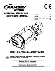
WINCH MOUNTING<br />
ESSENTIAL MOUNTING INSTRUCTIONS TO MAINTAIN ALIGNMENT OF PLANETARY WINCH COMPONENTS:<br />
It is most important that this winch be mounted<br />
CABLE DRUM<br />
securely so that the three major sections (the motor<br />
end, the cable drum, and the gear housing end) are<br />
properly aligned. Ex<strong>ce</strong>ssive bushing wear and difficulty<br />
in freespooling are usually symptoms of misalignment.<br />
In the as-installed condition, if the winch is midmounted,<br />
then at least one tie-plate must be attached<br />
to the mounting feet at the bottom of the winch to<br />
maintain alignment. If the winch is foot mounted then<br />
at least one tie-plate must remain mounted at midpoint<br />
of winch to maintain alignment. It is always preferred<br />
to used BOTH tie-plates in the final installed configuration.<br />
Angle Mounting Kit, P/N 251173 is recommended for<br />
maximum ease in mounting the winch. The angle kit<br />
will allow the winch to be mounted in upright or midmount<br />
applications and will meet the criteria of serving<br />
as a solid and true mounting surfa<strong>ce</strong>.<br />
When mounting the winch with other than the recommended<br />
MOTOR END<br />
FOOT MOUNT<br />
MID MOUNT<br />
GEAR HOUSING END<br />
TIEPLATE AT SIDE LOCATION<br />
TIEPLATE AT FOOT (BASE) LOCATION<br />
<strong>Ramsey</strong> Angle Kit, the mounting hole patterns described in the Dimensional drawings on pages 11-12 should be used. The mount-<br />
ing surfa<strong>ce</strong> must be flat within .015 inch and sufficiently stiff to resist flexing. If a steel plate is used for foot mounting, it should be .750 inch<br />
thick. For this mounting application eight (8) 5/8-11NC x 1-1/2” long grade 5 capscrews with lockwashers will be needed to mount winch.<br />
Capscrews should be tightened to 173 ft-lb (235 Nm) torque.<br />
NOTE: If angles or a steel plate are used in mounting winch, tie-plates provided with winch are to be attached to the remaining mounting<br />
pads, whether they be side or foot.<br />
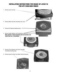
CABLE INSTALLATION<br />
1. Unwind cable by rolling it out along the ground<br />
to prevent kinking. Securely wrap end of cable,<br />
opposite hook, with plastic or similar tape to<br />
prevent fraying.<br />
2. Pla<strong>ce</strong> taped end of cable into hole in cable drum<br />
as shown below. Use the 3/8-16NC x 1/2” long<br />
hex socket drive setscrew (part of drum assembly<br />
item 234171) to secure cable to drum.<br />
3. Carefully run winch in the "reel-in" direction.<br />
Keeping tension on end of cable, spool all the<br />
cable onto the cable drum, taking care to form<br />
neatly wrapped layers.<br />
After installing cable, check freespool operation.<br />
Disengage clutch and pull on cable at a walking<br />
speed. If cable “birdnests”, loosen jam nut (item<br />
#22) and turn nylon setscrew (item #19) clockwise<br />
to increase drag on drum. If cable pull is<br />
ex<strong>ce</strong>ssive, loosen nylon setscrew by turning counterclockwise.<br />
Tighten jam nut when proper setting is<br />
obtained.<br />
CAUTION: OVER-TIGHTENING OF JAM NUT MAY STRIP NYLON SETSCREW.<br />
22<br />
19<br />
4