noz DIN24554 11/2010 - HEB Hydraulik - Elementebau GmbH
noz DIN24554 11/2010 - HEB Hydraulik - Elementebau GmbH
noz DIN24554 11/2010 - HEB Hydraulik - Elementebau GmbH

You also want an ePaper? Increase the reach of your titles
YUMPU automatically turns print PDFs into web optimized ePapers that Google loves.
<strong>DIN24554</strong>-7-2012<br />
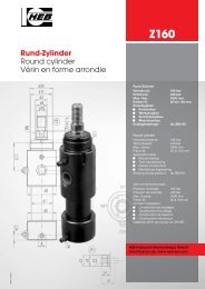
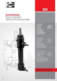
Norm-Zylinder<br />
DIN standard cylinder<br />
Vérin normalisé<br />
<strong>DIN24554</strong><br />
Norm-Zylinder<br />
Nenndruck: 160 bar<br />
Prüfdruck: 240 bar<br />
Max. Hub: 3000 mm<br />
Kolben Ø: 25 bis 200 mm<br />
Einsatzgebiet:<br />
• Formenbau<br />
• Werkzeugbau<br />
• Vorrichtungsbau<br />
Endlagenabfrage: Nein<br />
DIN standard cylinder<br />
Nominal pressure: 160 bar<br />
Test pressure: 240 bar<br />
Max. stroke: 3000 mm<br />
Piston Ø: 25 to 200 mm<br />
Application area:<br />
• Mould-making<br />
• Tool manufacturing<br />
• Fixture<br />
Sensing of end position: No<br />
Vérin normalisé<br />
Pression nominale: 160 bar<br />
Pression de contrôle: 240 bar<br />
Max. Course: 3000 mm<br />
Piston Ø: 25 à 200 mm<br />
Domain d’utilisation:<br />
• Construction de moulages<br />
• Construction d’outillage<br />
• Construction de fixations<br />
Détection de fin de course: Non<br />
<strong>HEB</strong> <strong>Hydraulik</strong>-<strong>Elementebau</strong> <strong>GmbH</strong><br />
info@heb-zyl.de, www.heb-zyl.com
•<br />
•<br />
•<br />
•<br />
•<br />
•<br />
•<br />
Allgemeine Beschreibung<br />
und Hinweise<br />
Bauweise:<br />
Rundzylinder in bewährter Schraubkonstruktion<br />
(mit quadratischem Zylinderboden<br />
und -kopf) nach <strong>DIN24554</strong><br />
Kolbenstangenlauffläche hartverchromt,<br />
geschliffen und poliert<br />
Kolben-Ø und Kolbenstangen-Ø nach<br />
DIN/ISO 3320<br />
Hübe (Hubtoleranz DIN/ISO 2768m):<br />
nach Kundenwunsch 0,1mm bis<br />
3000mm<br />
Bei großen Hublängen ist die maximal<br />
zulässige Knickbelastung zu beachten<br />
(siehe Knickbelastungsdiagramm)<br />
Kolbengeschwindigkeit:<br />
Für höhere Geschwindigkeiten ist eine<br />
Änderung der Anschlussgrößen<br />
und eine Endlagendämpfung oder externe<br />
Hubbegrenzung notwendig<br />
(Bitte konsultieren Sie uns)<br />
Die Endlagendämpfung mit progressivem<br />
Übergang in die Dämpfungsphase<br />
ist grundsätzlich ab Durchmesser<br />
25mm regelbar lieferbar<br />
2<br />
General description and informations<br />
Construction:<br />
Roundcylinder in proven screwed cylinder<br />
design (with a square cylinder base<br />
and head) according to <strong>DIN24554</strong><br />
Piston-rods hard-chrome plated, ground<br />
and polished<br />
Piston-Ø and Piston-rod-Ø according<br />
to DINS/ISO 3320<br />
Strokes (Stroke tolerance according to<br />
DIN/ISO 2768m): according to the wishes<br />
of the customers 0,1mm to<br />
3000mm<br />
With large strokes consider the maximum<br />
permissible buckling load (see<br />
buckling load diagram)<br />
Piston speed:<br />
For higher speeds is a change of dimensions<br />
of connections and a strokeend<br />
damping or external stroke limitation<br />
are required (please contact us)<br />
The stroke-end damping with progressive<br />
transition to damping phase available<br />
for piston diameters above 25mm<br />
adjustable<br />
Description générale et des<br />
informations<br />
Construction:<br />
Vérin en forme arrondie dans éprouvée<br />
modéle de cylindre vissé (avec un base et<br />
un culasse carrée) selon <strong>DIN24554</strong><br />
Tiges de piston chromées durement,<br />
meulées es polies<br />
Ø piston et Ø tiges de piston selon<br />
DIN/ISO 3320<br />
Course (Tolérance de course conformes<br />
à la norme DIN/ISO 2768m): Course<br />
réglable, à la demande du client 0,1mm<br />
à 3000mm<br />
Avec de grandes courses considérer le<br />
maximum de charge de flambement admissible<br />
est observée (voir flambement<br />
diagramme de charge)<br />
Vitesse du piston:<br />
Pour des vitesses supérieures est un<br />
changement de dimensions de connexions<br />
et un amortissement de fin de course<br />
ou externe limitation de course sont<br />
nécessaires (s'il vous plaît contacteznous)<br />
L'amortissement en fin de course - passage<br />
progressif à la phase d'amortissement<br />
- livrable avec des pistons à 25mm<br />
et plus réglable<br />
<strong>HEB</strong> <strong>Hydraulik</strong>-<strong>Elementebau</strong> <strong>GmbH</strong> / Tel. (0761) 13099-0, Fax (0761) 13 50 66<br />
<strong>DIN24554</strong>
<strong>DIN24554</strong><br />
• Die Kolbenstangendichtung besteht<br />
standardmäßig aus einem PU-Nutring<br />
(weitere Dichtungsvarianten auf<br />
Anfrage)<br />
•<br />
•<br />
•<br />
•<br />
Allgemeine Beschreibung<br />
und Hinweise<br />
Dichtung:<br />
Die Kolbendichtung besteht standardmäßig<br />
aus PTFE und ist besonders<br />
reibungsarm, alternativ für statische<br />
Dichtheit gibt es eine spezielle<br />
Dichtung (S35)<br />
Die Standarddichtungen sind für Hydroflüssigkeiten<br />
der Typen H, HL, HLP<br />
nach DIN 51524 / 51525 und den Temperaturbereich<br />
von -20°C bis +90°C<br />
geeignet<br />
Beim Betrieb mit anderen Druckflüssigkeiten<br />
oder höheren Temperaturen<br />
sind andere Dichtungswerkstoffe erforderlich<br />
(bitte beachten Sie unsere<br />
Sonderaussattungen oder kontaktieren<br />
Sie uns)<br />
Grundsätzlich erhältlich sind veränderte<br />
Bauformen, Zylinder mit Kühlung<br />
sowie Sonderanfertigungen<br />
nach Kundenwunsch - bitte kontaktieren<br />
Sie uns<br />
General description and informations<br />
Seal:<br />
The piston rod seal typically consists of<br />
a PU-ring in groove (other seals on request)<br />
The piston seal typically consists of PT-<br />
FE and is extremely low friction, as an<br />
alternative for static sealing there is a<br />
special seal (S35)<br />
The standard seals are suitable to hydraulic<br />
fluids of the type H, HL, HLP according<br />
to DIN51524/51525 and to temperatures<br />
from -20°C to +90°C<br />
For operation with other fluids or higher<br />
temperatures, other sealing materials<br />
are required (please note our special<br />
equipment or contact us)<br />
Generally available are altered designs,<br />
cylinder with cooling as well as custom<br />
made cylinders - please contact us<br />
Description générale et des<br />
informations<br />
Joint:<br />
Le joint de tige se compose généralement<br />
d'un PU-anneau (autres joints sur<br />
demande)<br />
Le joint de piston se compose généralement<br />
de PTFE et de frottement extrêmement<br />
faible, comme une alternative<br />
pour étanchéité statique est un sceau<br />
spécial (S35)<br />
Les joints standard sont concus pour de<br />
fluides hydrauliques des types H, HL,<br />
HLP conformément aux normes<br />
DIN51524/51525 et pour des températures<br />
de -20°C à +90°C<br />
Pour le fonctionnement avec d'autres<br />
fluids hydrauliques ou des températures<br />
plus élevées, autres matériaux<br />
d'étanchéité sont requis (s'il vous plaît<br />
noter que notre équipement spécial ou<br />
contactez-nous)<br />
Généralement disponibles sont modifiées<br />
conçoit, cylindre à refroidissement<br />
ainsi que les bouteilles fabriquées sur<br />
mesure - s'il vous plaît contactez-nous<br />
<strong>HEB</strong> <strong>Hydraulik</strong>-<strong>Elementebau</strong> <strong>GmbH</strong> / Tel. (0761) 13099-0, Fax (0761) 13 50 66 3
Technische Daten Technical data Caractéristiques techniques<br />
Kolben - Ø mm 25 32 40 50 63 80 100 125 160<br />
Piston - Ø mm • Piston - Ø mm<br />
Kolbenstangen - Ø 1 mm 12 14 18 22 28 36 45 56 70<br />
Piston rod - Ø mm • Tige de piston - Ø mm<br />
Kolbenstangen - Ø 2 mm 18 22 28 36 45 56 70 90 <strong>11</strong>0<br />
Piston rod - Ø mm • Tige de piston - Ø mm<br />
Kolbenfläche stoßend - cm 2 • Piston area extending - cm 2 • Surface de piston poussante - cm 2<br />
4,9 8,0 12,6 19,6 31,2 50,2 78,5 122,6 201,0<br />
Kolbenfläche 1 ziehend - cm 2 • Piston area retracting - cm 2 • Surface de piston tirante - cm 2<br />
3,7 6,4 10,0 15,8 25,0 40,01 62,6 98 162,5<br />
Kolbenfläche 2 ziehend - cm 2 • Piston area retracting - cm 2 • Surface de piston tirante - cm 2<br />
2,4 4,2 6,5 9,4 15,3 25,6 40 59 106,0<br />
Kolbenkraft stoßend - daN • Piston force extending - daN • Force de piston poussante - daN<br />
80 bar 392 640 1000 1570 2490 4010 6280 9800 16080<br />
100 bar 490 800 1260 1960 3120 5020 7850 12260 <strong>2010</strong>0<br />
120 bar 588 960 1510 2350 3740 6020 9420 14710 24120<br />
140 bar 686 <strong>11</strong>20 1760 2740 4360 7020 10990 17160 28140<br />
160 bar 784 1280 <strong>2010</strong> 3130 4990 8030 12560 19610 32160<br />
Kolbenkraft 1 ziehend - daN • Piston force retracting - daN • Force de piston tirante - daN<br />
80 bar 296 512 800 1264 2000 3200 5008 7840 13000<br />
100 bar 370 640 1000 1580 2500 4000 6260 9800 16250<br />
120 bar 444 768 1200 1896 3000 4800 7512 <strong>11</strong>760 19500<br />
140 bar 518 896 1400 2212 3500 5600 8764 13720 22750<br />
160 bar 592 1024 1600 2528 4000 6400 10016 15680 26000<br />
Kolbenkraft 2 ziehend - daN • Piston force retracting - daN • Force de piston tirante - daN<br />
80 bar 192 336 520 752 1224 2048 3200 4720 8480<br />
100 bar 240 420 650 940 1530 2560 4000 5900 10600<br />
120 bar 288 504 780 <strong>11</strong>28 1836 3072 4800 7080 12720<br />
140 bar 336 588 910 1316 2142 3584 5600 8260 14840<br />
160 bar 384 672 1040 1504 2448 4096 6400 9440 16960<br />
Dämpfungsweg <strong>11</strong> 15 16 18 18 20 22 26 30<br />
Damping path • Course d’amortissement<br />
Kolben - Ø mm 25 32 40 50 63 80 100 125 160<br />
Piston - Ø mm • Piston - Ø mm<br />
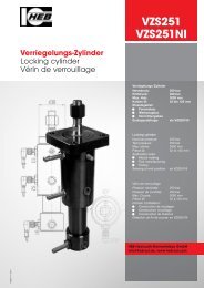
Sonderausstattungen Special equipments Équipements optionnels<br />
• Hochhitzebeständige Dichtungen für Hydroflüssigkeiten der Typen H, HL, HLP – DIN 51524/51525<br />
und Temperaturen ab +100°C bis +200°C<br />
High heat-resistant seals for hydraulic fluids type H, HL, HLP – German Standard DIN 51524/51525<br />
and for temperatures from +100°C up to +200°C<br />
Garnitures réstistantes aux températures très élevées pour liquides type H, HL, HLP – DIN 51524/51525<br />
et des températures de +100°C jusqu’ à +200°C<br />
• Beidseitige Entlüftungsschrauben für Schlauchanschluß<br />
On both sides bleeder screws for flexible tube connection<br />
Sur le deux côtés vis de purge d’air pour raccord de tuyau<br />
• Kolbenstangenlauffläche gehärtet und hartverchromt<br />
Piston-rod hardened and hard-chrome plated<br />
Tige de piston trempée et chromée durement<br />
• Kolbenstange aus V2A, Werkstoff 1.4301, hartverchromt<br />
Piston-rod stainless steal, mat. no. 1.4301, hard-chrome plated<br />
Tige du piston en acier inoxydable, matériau numeró 1.4301, chromée durement<br />
• Kolbenstangengewinde d2G, L3 + L4 passend für Gelenkköpfe (unbedingt Typ bekanntgeben)<br />
Piston-rod thread d2G, L3 and L4 for rod ends S 19 (it is essential that you give the type)<br />
Filetage tige de piston d2G, L3 + L4 pour rotule (indiquer le type)<br />
• Kolben statisch dicht<br />
Piston with static sealing effect<br />
Piston avec effet hermétique<br />
• Spezialdichtungen entsprechend den Einsatzbedingungen nach Kundenwunsch.<br />
Special seals corresponding to the conditions of use according to the specification of the customers.<br />
Garnitures spéciales conformes aux conditiones d’application selon la spécification du client.<br />
4 <strong>HEB</strong> <strong>Hydraulik</strong>-<strong>Elementebau</strong> <strong>GmbH</strong> / Tel. (0761) 13099-0, Fax (0761) 13 50 66<br />
<strong>DIN24554</strong><br />
S5<br />
S7<br />
S13<br />
S14<br />
S19<br />
S35
<strong>DIN24554</strong><br />
Funktionsarten Modes of operation Modes de fonctionnement<br />
200<br />
201<br />
206<br />
209<br />
2<strong>11</strong><br />
213<br />
214<br />
216<br />
218<br />
Sinnbild nach DIN/ISO 1219/1 • Symbol according to DIN/ISO 1219/1 •<br />
Symbole selon DIN/ISO 1219/1<br />
Bezeichnung • Order specification • Référence de commande<br />
Beschreibung Description<br />
einfachwirkend,<br />
stoßend arbeitend,<br />
Rücklauf durch äußere Kraft<br />
einfachwirkend,<br />
ziehend arbeitend,<br />
Rücklauf durch äußere Kraft<br />
doppeltwirkend,<br />
auf beiden Seiten<br />
das gleiche Medium<br />
doppeltwirkend,<br />
Endlagendämpfung beidseitig,<br />
regelbar ab Kolben Ø 25<br />
doppeltwirkend,<br />
Endlagendämpfung vorn,<br />
regelbar ab Kolben Ø 25<br />
doppeltwirkend,<br />
Endlagendämpfung hinten,<br />
regelbar ab Kolben Ø 25<br />
doppeltwirkend,<br />
durchgehende Kolbenstange<br />
doppeltwirkend,<br />
durchgehende Kolbenstange,<br />
Endlagendämpfung beidseitig,<br />
regelbar ab Kolben Ø 25<br />
★★★ doppeltwirkend,<br />
durchgehende Kolbenstange,<br />
Endlagendämpfung einseitig,<br />
regelbar ab Kolben Ø 25<br />
★★★ Lage der Dämpfung, bezogen auf die Befestigungsart, bitte angeben<br />
Indicate the position of the damping concerning the fixation system<br />
Indiquer la position de l’amortissement concernant la mode de fixation<br />
simple-acting,<br />
pushing action,<br />
return by external force<br />
simple acting,<br />
drawing action,<br />
return by external force<br />
souble-acting,<br />
on both sides<br />
the same medium<br />
double-acting,<br />
cushioning on both sides,<br />
adjustable above piston Ø 25<br />
double-acting,<br />
cushioning in front,<br />
adjustable above piston Ø 25<br />
double-acting,<br />
cushioning in the rear,<br />
adjustable above piston Ø 25<br />
double-acting,<br />
continous piston-rod<br />
double-acting,<br />
continous piston-rod,<br />
cushioning on both sides,<br />
adjustable above piston Ø 25<br />
★★★ double-acting,<br />
continous piston-rod,<br />
cushioning on one side,<br />
adjustable above piston Ø 25<br />
Description<br />
à simple effet,<br />
poussant,<br />
retour par force extérieur<br />
à simple effet,<br />
tirant,<br />
retour par force extérieur<br />
à double effet,<br />
sur les deux côtés<br />
le même milieu<br />
à double effet,<br />
amortissement des deux côtés,<br />
adjustable à Ø piston 25 et plus<br />
à double effet,<br />
amortissement au front,<br />
adjustable à Ø piston 25 et plus<br />
à double effet,<br />
amortissement au dos,<br />
adjustable à Ø piston 25 et plus<br />
à double effet,<br />
tige de piston continuante<br />
à double effet,<br />
tige de piston continuante,<br />
amortissement des deux côtés,<br />
adjustable à Ø piston 25 et plus<br />
★★★ à double effet,<br />
tige de piston continuante,<br />
amortissement d’un côté,<br />
adjustable à Ø piston 25 et plus<br />
e-mail: info@heb-zyl.de / homepage: http://www.heb-zyl.com 5
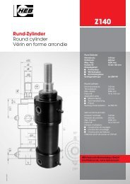
Übersicht der lieferbaren Summary of the deliverable Apercu sur les modes de<br />
Bauformen construction forms construction livrables<br />
6<br />
Bezeichnung<br />
Order specification<br />
Référence de commande<br />
ME 5<br />
Seite / page 7/9<br />
ME 6<br />
Seite / page 7/9<br />
MT 4<br />
Seite / page 7/9<br />
MP 5<br />
Seite / page 8/9<br />
MS 2<br />
Seite / page 8/9<br />
Beschreibung<br />
Description<br />
Description<br />
• Rechteckiger Flansch am Zylinderkopf<br />
• Rectangular flange at the cylinder head<br />
• Bride rectangulaire à la tête du cylindre<br />
• Rechteckiger Flansch am Zylinderboden<br />
• Rectangular flange at the cylinder base<br />
• Bride rectangulaire au fond du cylindre<br />
• Schwenkzapfen variabel<br />
• Tilting adapter variable<br />
• Tourillon variable<br />
• Gelenklager am Zylinderboden<br />
• Joint bearing at the cylinder base<br />
• Appui articulé au fond du cylindre<br />
• Seitliche Fußbefestigung<br />
• Lateral base mount<br />
• Fixation latérale du pied<br />
e-mail: info@heb-zyl.de / homepage: http://www.heb-zyl.com<br />
<strong>DIN24554</strong>
<strong>DIN24554</strong><br />
Bauform Construction form Mode de construction<br />
Bezeichnung<br />
Order specification<br />
Référence de commande<br />
ME 5<br />
ME 5 DK<br />
ME 6<br />
MT 4<br />
MT 4 DK<br />
<strong>HEB</strong> <strong>Hydraulik</strong>-<strong>Elementebau</strong> <strong>GmbH</strong> / Tel. (0761) 1 30 99-0, Fax (0761) 13 50 66 7
Bauform Construction form Mode de construction<br />
Mögliche Lage der Leitungsanschlüsse und Dämpfungsdrosseln<br />
Position of the connections and of the damping throttles<br />
Position des raccords et de l’inductance de l’amortissement<br />
8<br />
Kolben- Ø mm<br />
Piston- Ø mm<br />
Piston- Ø mm<br />
25 Kopf - head - tête<br />
Boden - bottom - fond<br />
32 Kopf - head - tête<br />
Boden - bottom - fond<br />
40 Kopf - head - tête<br />
50 Boden - bottom - fond<br />
63 Kopf - head - tête<br />
80<br />
100<br />
Boden - bottom - fond<br />
125 Kopf - head - tête<br />
160 Boden - bottom - fond<br />
1 2 3 4 1 2 3 4 1 2 3 4 1 2 3 4 1 2 3 4 1 2 3 4<br />
1 2 3 4 1 2 3 4 1 2 3 4 1 2 3 4 1 2 3 4 1 2 3 4<br />
MP 5<br />
1 2 3 4 1 2 3 4<br />
1 2 3 4 1 2 3 4<br />
1 2 3 4 1 2 3 4 1 2 3 4 1 2 3 4 1 2 3 4 1 2 3 4 1 2 4 1 2 4 1 2 3 4 1 2 3 4<br />
1 2 3 4 1 2 3 4 1 2 3 4 1 2 3 4 1 2 3 4 1 2 3 4 1 2 4 1 2 4 1 2 3 4 1 2 3 4<br />
e-mail: info@heb-zyl.de / homepage: http://www.heb-zyl.com<br />
Bezeichnung<br />
Order specification<br />
Référence de commande<br />
MS 2<br />
MS 2 DK<br />
ME 5 / ME 5 DK ME 6 MP 5 MS 2 / MS 2 DK MT 4 / MT 4 DK<br />
Drossel Anschluss Drossel Anschluss Drossel Anschluss Drossel Anschluss Drossel Anschluss<br />
Throttle Connection Throttle Connection Throttle Connection Throttle Connection Throttle Connection<br />
Inductance Raccord Inductance Raccord Inductance Raccord Inductance Raccord Inductance Raccord<br />
3 1<br />
2 3 4 1<br />
2 3 4 1<br />
2 4 1<br />
2 3 4 1<br />
1 2 3 4 1 2 3 4 1 2 3 4 1 2 3 4 1 2 3 4 1 2 3 4 2 4 1<br />
1 2 3 4 1 2 3 4<br />
3 1<br />
2 3 4 1<br />
2 3 4 1<br />
2 4 1<br />
2 3 4 1<br />
1 2 3 4 1 2 3 4 1 2 3 4 1 2 3 4 1 2 3 4 1 2 3 4 2 4 1<br />
1 2 3 4 1 2 3 4<br />
1 3 1 3 1 2 3 4 1 2 3 4 1 2 3 4 1 2 3 4 2 4 1<br />
1 2 3 4 1 2 3 4<br />
1 2 3 4 1 2 3 4 1 2 3 4 1 2 3 4 1 2 3 4 1 2 3 4 2 4 1<br />
1 2 3 4 1 2 3 4<br />
• Standardlage der Dämpfungsdrosseln Zylinderseite 3 bzw. 2 siehe dunkle Markierung<br />
• Standard position of the damping throttles cylinder side 3 or 2 see the dark marking<br />
• Position standard de l’inductance d’amortissement côté du cylindre 3 ou bien 2 voir le marquage foncé<br />
• Standardlage der Leitungsanschlüsse Zylinderseite 1 siehe helle Markierung<br />
• Standard position of the branch circuit connections cylinder side 1 see the bright marking<br />
• Position standard des raccords de conduction côté du cylindre 1 voir le marquage de couleur claire<br />
2 4 1<br />
2 4 1<br />
<strong>DIN24554</strong>
<strong>DIN24554</strong><br />
Bauform Construction form Mode de construction<br />
Kolben - Ø • piston Ø • piston Ø 25 32 40 50 63 80 100 125 160<br />
Stangen - Ø MM • rod Ø • Ø tige 12 18 14 22 18 28 22 36 28 45 36 56 45 70 56 90 70 <strong>11</strong>0<br />
d8-Ø x Länge • Ø x lenght<br />
Ø x longueur<br />
Ø<strong>11</strong>,5<br />
x5<br />
Ø17,5<br />
x5<br />
Ø13,5<br />
x7<br />
Ø21<br />
x7<br />
Ø17<br />
x6<br />
Ø27<br />
x6<br />
RD - Ø (f8) 38 38 42 42 62 62 74 74 75 88 82 105 92 125 105 150 125 170<br />
B - Ø 24 30 26 34 30 42 34 50 42 60 50 72 60 88 72 108 88 133<br />
VE 16 22 22 25 29 29 32 32 32<br />
DR - Ø 35 40 50 65 83 100 125 150 190<br />
BD 16 20 25 35 40 50 60 80 100<br />
CX 12 16 20 25 30 40 50 60 80<br />
Grenzabmaße<br />
tolerance of measurement 0-0,008 0-0,008 0-0,012 0-0,012 0-0,012 0-0,012 0-0,012 0-0,015 0-0,015<br />
tolérance de mesures<br />
E 40 45 63 75 90 <strong>11</strong>5 130 165 205<br />
EP 8 <strong>11</strong> 13 17 19 23 30 38 47<br />
EX 10 14 16 20 22 28 35 44 55<br />
Grenzabmaße<br />
tolerance of measurement 0-0,12 0-0,12 0-0,12 0-0,12 0-0,12 0-0,12 0-0,12 0-0,15 0-0,15<br />
tolérance de mesures<br />
F 10 10 10 16 16 20 22 22 25<br />
FB - Ø 5,5 6,5 <strong>11</strong> 14 14 18 18 22 26<br />
GF 25 25 38 38 38 45 45 58 58<br />
GK 56 59 71 70 75 89 79 99 <strong>11</strong>3<br />
GB 42 45 62 62 69 83 73 98 <strong>11</strong>3<br />
GH 25 25 30 35 42 45 60 60 75<br />
H 45 50 - - - - - - -<br />
J 25 25 38 38 38 45 45 58 58<br />
LH h10 19 22 31 37 44 57 63 82 101<br />
LT 16 20 25 31 38 48 58 72 92<br />
MS 20 22,5 29 33 40 50 62 80 100<br />
PJ (+ Hub + stroke + course) 53 56 73 74 80 93 101 <strong>11</strong>7 130<br />
PK (+ Hub + stroke + course) 53 57 73 74 80 93 102 <strong>11</strong>8 130<br />
R 27 33 41 52 65 83 97 126 155<br />
SB - Ø 6,6 9 <strong>11</strong> 14 18 18 26 26 33<br />
SK (+ Hub + stroke + course) 87 87 107 100 92 <strong>11</strong>1 108 132 130<br />
SS (+ Hub + stroke + course) 73 73 98 92 86 105 102 131 130<br />
ST 8,5 12,5 12,5 19 26 26 32 32 38<br />
TD - Ø (f8) 12 16 20 25 32 40 50 63 80<br />
TM 48 55 76 89 100 127 140 178 215<br />
TO 51 58 87 105 <strong>11</strong>7 149 162 208 253<br />
TS 54 63 83 102 124 149 172 210 260<br />
UM 68 79 108 129 150 191 220 278 341<br />
UO 65 70 <strong>11</strong>0 130 145 180 200 250 300<br />
US 72 84 103 127 161 186 216 254 318<br />
UW 55 70 90 100 120 150 170 210 250<br />
Y 50 60 62 67 71 77 82 86 86<br />
XO (+ Hub + stroke + course) 130 148 178 190 206 238 261 304 337<br />
XS 33 45 45 54 65 68 79 79 86<br />
XV nach Kundenwunsch, bei Auftragserteilung bitte gewünschtes Maß angeben<br />
On request, please state the dimension required in your order • Sur demande du client, á la commande indiquer la dimension souhaitée.<br />
XV min. (+ Hub + stroke + course) 89 104 <strong>11</strong>9 129 143 165 166 196 220<br />
XV max. (+ Hub + stroke + course) 64 73 78 79 79 82 100 94 82<br />
Mindesthub bei Bauform • Minimum stroke for construction form • Course minimale pour le mode de construction<br />
MT4 25 31 41 50 64 83 66 102 138<br />
ME5, ME6, MP5, MS2 13 14 18 17 28 37 <strong>11</strong> 27 44<br />
Z min. 3° 3° 3° 3° 3° 3° 3° 3° 3°<br />
Zj + Hub • stroke • course <strong>11</strong>4 128 153 159 168 190 203 232 245<br />
ZK + Hub • stroke • course 128 142 163 167 174 196 209 233 245<br />
B1: (Standard) KK M10x1,25 M12x1,25 M14x1,5 M16x1,5 M20x1,5 M27x2 M33x2 M42x2 M48x2<br />
A 14 16 18 22 28 36 45 56 63<br />
MF 25 35 35 41 48 51 57 57 57<br />
SW 10 15 12 19 15 24 19 30 24 36 30 46 36 60 46 75 60 90<br />
EE (Anschluß • connection • raccord) G1/4 G1/4 G3/8 G1/2 G1/2 G3/4 G3/4 G1 G1<br />
<strong>HEB</strong> <strong>Hydraulik</strong>-<strong>Elementebau</strong> <strong>GmbH</strong> / Tel. (0761) 1 30 99-0, Fax (0761) 13 50 66<br />
Ø21<br />
x8<br />
Ø35<br />
x9<br />
Ø27<br />
x13<br />
Ø44<br />
x13<br />
Ø35<br />
x12<br />
Ø55<br />
x18<br />
Ø43<br />
x12<br />
Ø69<br />
x20<br />
Ø55<br />
x18<br />
Ø88<br />
x18<br />
Ø69<br />
x20<br />
Ø109<br />
x20<br />
9
Norm-Zylinder / DIN standard cylinder / Vérin normalisé <strong>DIN24554</strong><br />
Typenschlüssel Code Clé des types<br />
Anhand der lieferbaren Befestigungsund<br />
Funktionsarten kann der gewünschte<br />
Zylindertyp gemäß folgendem<br />
Schlüssel festgelegt werden:<br />
By means of the deliverable fixation<br />
systems and modes of operation the desired<br />
cylinder type can be fixed according<br />
to the following code:<br />
Zylindertyp • Cylinder type • Type de cylindre<br />
Bauform • Construction form • Mode de construction<br />
Kolben Ø mm • Piston Ø mm • Ø piston mm<br />
Kolbenstangen Ø mm • Piston-rod Ø mm • Ø Tige de piston mm<br />
Hub • Stroke • Course<br />
Funktionsart • Mode of operation • Mode de fonctionnement<br />
Kolbenstangenende • Piston-rod end • Fin de la tige de piston<br />
Sonderausstattungen • Special equipments • Equipements spéciaux<br />
Lage der Dämpfungsdrossel, kolbenseitig<br />
Position of the damping throttle, piston-side • Position de l'inductance d'amortissement, côté piston<br />
Lage der Dämpfungsdrossel, stangenseitig<br />
Position of the damping throttle, rod-side • Position de l'inductance d'amortissement, côté tige<br />
Lage des Anschlußes, kolbenseitig • Position of the connection, piston-side • Position de raccord, côté piston<br />
Lage des Anschlußes, stangenseitig • Position of the connection, rod-side • Position de raccord, côté tige<br />
Au moyen des modes de fixation et<br />
de fonctionnement livrables le type de<br />
cylindre désiré selon la clé suivante:<br />
Bestellbeispiel Example of order Exemple de commande<br />
<strong>DIN24554</strong> - ME5 - 50 / 22 / 100,00 - 209 / B1 / S5 / 3 / 3 / 1 / 1<br />
<strong>HEB</strong>-Normzylinder<br />
für Betriebsdruck bis 160 bar nach DIN 24554<br />
ME5 = rechteckiger Flansch am Zylinderkopf<br />
Kolben Ø 50 mm, Kolbenstangen Ø 22 mm,<br />
Hub 100,00 mm<br />
209 = doppeltwirkend,<br />
Endlagendämpfung beidseitig<br />
B1 = Kolbenstangenende<br />
mit Außengewinde<br />
S5 = hochhitzebeständige Dichtungen<br />
für Hydroflüssigkeiten der Typen H, Hl, HLPDIN<br />
51524 / 51525 und Temperaturen ab +100°C bis<br />
+200°C<br />
3 = Lage der Dämpfungsdrossel,<br />
kolbenseitig<br />
3 = Lage der Dämpfungsdrossel,<br />
stangenseitig<br />
1 = Lage des Anschlußes,<br />
kolbenseitig<br />
1 = Lage des Anschlußes,<br />
stangenseitig<br />
Sämtliche Zylinder unserer Fertigung sind mit genauer Typenbezeichnung bzw. Ident.-Nr. und der Kom.-Nr., die zusätzlich eingraviert wird, gekennzeichnet.<br />
Eine absolut einwandfreie Identifizierung bei Ersatzteilbeschaffung und Ersatzteilbezug ist hierdurch gewährleistet.<br />
All cylinders of our production are provided with the exact order specification respectively the number of identification and the commission number which<br />
is additionally stamped on the cylinder. By this an absolutely perfect identification in case of order and purchase of spare parts is guaranteed.<br />
Tous les cylindres de notre production sont marqués avec la référence de commande exacte ou bien le numéro d’identification et le numéro de commission<br />
qui est estampé additionnellement. Une identification absolument correcte pour l’acquisition des éléments de rechange est garantie par cela.<br />
10<br />
Änderungen vorbehalten.<br />
Subject to change without notice.<br />
Modification resérvée.<br />
<strong>DIN24554</strong> ME5 50 22 100,00 209 B1 S5 3 3 1 1<br />
<strong>HEB</strong> DIN standard cylinder<br />
for operating pressure up to 160 bar according<br />
to DIN 24554<br />
ME5 = rectangular flange at the<br />
cylinder head<br />
piston Ø 50 mm, piston-rod Ø 22 mm,<br />
stroke 100,00 mm<br />
209 = double-acting,<br />
cushioning on both sides.<br />
B1 = piston-rod end with external<br />
thread<br />
S5 = high heat-resistant seals for<br />
hydraulic fluids type H, HL, HLP - German<br />
Standard DIN 51524/51525 and for<br />
températures from +100°C up to +200°C<br />
3 = position of the damping throttle,<br />
piston-side<br />
3 = position of the damping throttle,<br />
rod-side<br />
1 = position of the connection,<br />
piston-side<br />
1 = position of the connection, rod-side<br />
<strong>HEB</strong> vérin normalisé<br />
pour pression fonctionnement jusqu’à<br />
160 bar selon DIN 24554<br />
ME5 = bride rectangulaire à la tête<br />
du cylindre<br />
Ø piston 50 mm, Ø tige de piston 22 mm,<br />
course 100,00 mm<br />
209 = à double effet,<br />
amortissement des deux côtés<br />
B1 = fin de la tige de piston<br />
avec filet extérieur<br />
S5 = garnitures résistantes aux<br />
températures très élevées pour liquides type<br />
H, HL, HLP - DIN 51524/51525 et des<br />
températures de +100°C jusqu`à 200°C<br />
3 = position de l'inductance<br />
d'amortissement, côté piston<br />
3 = position de l'inductance<br />
d'amortissement, côté tige<br />
1 = position de raccord, côté piston<br />
1 = position de raccord, côté tige<br />
Achtung - Typenbezeichnung bzw. Ident.Nr. sowie Kom.Nr. bei Ersatzbeschaffung und<br />
Ersatzteilbezug unbedingt angeben.<br />
Attention - In case of order and purchase of spare parts it is absolutely necessary to indicate<br />
the order specification or the number of identification as well as the commission number.<br />
Attention - En cas d’acquisition des éléments de rechange indiquer absolutement la référence<br />
de commande ou bien le numéro d’identification ainsi que le numéro de commission.<br />
<strong>HEB</strong> <strong>Hydraulik</strong>-<strong>Elementebau</strong> <strong>GmbH</strong> / Tel. (0761) 1 30 99-0, Fax (0761) 13 50 66<br />
<strong>DIN24554</strong>