MSAT 102-122-142-162-182-202-242
MSAT 102-122-142-162-182-202-242 MSAT 102-122-142-162-182-202-242
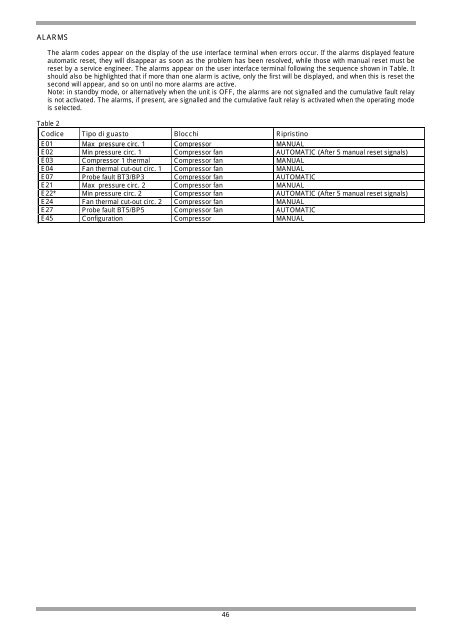
ALARMS The alarm codes appear on the display of the use interface terminal when errors occur. If the alarms displayed feature automatic reset, they will disappear as soon as the problem has been resolved, while those with manual reset must be reset by a service engineer. The alarms appear on the user interface terminal following the sequence shown in Table. It should also be highlighted that if more than one alarm is active, only the first will be displayed, and when this is reset the second will appear, and so on until no more alarms are active. Note: in standby mode, or alternatively when the unit is OFF, the alarms are not signalled and the cumulative fault relay is not activated. The alarms, if present, are signalled and the cumulative fault relay is activated when the operating mode is selected. Table 2 Codice Tipo di guasto Blocchi Ripristino E01 Max pressure circ. 1 Compressor MANUAL E02 Min pressure circ. 1 Compressor fan AUTOMATIC (After 5 manual reset signals) E03 Compressor 1 thermal Compressor fan MANUAL E04 Fan thermal cut-out circ. 1 Compressor fan MANUAL E07 Probe fault BT3/BP3 Compressor fan AUTOMATIC E21 Max pressure circ. 2 Compressor fan MANUAL E22* Min pressure circ. 2 Compressor fan AUTOMATIC (After 5 manual reset signals) E24 Fan thermal cut-out circ. 2 Compressor fan MANUAL E27 Probe fault BT5/BP5 Compressor fan AUTOMATIC E45 Configuration Compressor MANUAL 46
TROUBLESHOOTING The following provides indications on some possible anomalies and their corresponding solutions. The resulting operations are the full responsibility of the person performing them. An authorised technician possessing the legal requisites for each operation must be contacted to reset the operation of the unit. The activation of a safety device indicates an operating anomaly: before resetting the device, check and eliminate the causes of the anomaly. The following are possible problems and their corresponding causes and solutions. WARNING THE OPERATIONS SHOWN HERE ARE THE FULL RESPONSIBILITY OF THE PERSON PERFORMING THEM; AN AUTHORISED TECHNICIAN POSSESSING THE LEGAL REQUISITES FOR EACH OPERATION MUST BE CONTACTED TO RESET THE CORRESPONDING FUNCTION. All faults and anomalous operating conditions are handled by the main control module. When an anomalous condition or fault arises, the module, as well as placing the unit in safety mode, can display the event remotely. 47
- Page 1: MSAT 102-122-142-162-182-202-242 UN
- Page 4 and 5: GENERALE AVVERTENZE GENERALI Il pre
- Page 6 and 7: POSIZIONAMENTO Le unità sono proge
- Page 8 and 9: RICEVIMENTO CONTROLLO AL RICEVIMENT
- Page 10 and 11: COLLEGAMENTI ELETTRICI IMPORTANTE A
- Page 12 and 13: MESSA IN FUNZIONE TUTTE LE APPARECC
- Page 14 and 15: REGOLAZIONE MODALITA' DI FUNZIONAME
- Page 16 and 17: PANNELLO DEL MODULO DI CONTROLLO PR
- Page 18 and 19: ALLARMI I codici di allarme compaio
- Page 20 and 21: BLOCCO ALTA PRESSIONE BLOCCO ALTA P
- Page 22 and 23: INTERVENTO SICUREZZA COMPRESSORE IN
- Page 24 and 25: MANUTENZIONE ORDINARIA IMPORTANTE P
- Page 26 and 27: CONTROLLO PERDITE - Controllare acc
- Page 28 and 29: RISCHI GENERICI Zona considerata Ri
- Page 30 and 31: 11 Informazioni tossicologiche 12 I
- Page 32 and 33: GENERAL GENERAL WARNINGS The conten
- Page 34 and 35: POSITIONING The units are designed
- Page 36 and 37: RECEPTION INSPECTION UPON RECEIPT T
- Page 38 and 39: ELECTRICAL CONNECTIONS IMPORTANT MA
- Page 40 and 41: START-UP ALL THE EQUIPMENT MUST BE
- Page 42 and 43: CONTROL OPERATION OF THE MAIN MODUL
- Page 44 and 45: MAIN CONTROL MODULE PANEL LED 1 com
- Page 48 and 49: HIGH PRESSURE SHUTDOWN HIGH PRESSUR
- Page 50 and 51: COMPRESSOR CUT-OUT COMPRESSOR CUT-O
- Page 52 and 53: ROUTINE MAINTENANCE IMPORTANT MAKE
- Page 54 and 55: CHECKING FOR LEAKS - Carefully chec
- Page 56 and 57: GENERAL RISKS Particular area Dange
- Page 58 and 59: 12 Ecological information Forane 32
- Page 60 and 61: ALLGEMEINES ALLGEMEINE HINWEISE Das
- Page 62 and 63: GERÄTEAUFSTELLUNG Die Geräte sind
- Page 64 and 65: ÜBERNAHME EINGANGSKONTROLLE Die Ge
- Page 66 and 67: ELEKTRISCHE ANSCHLÜSSE ACHTUNG ALL
- Page 68 and 69: INBETRIEBNAHME SÄMTLICHE GERÄTE S
- Page 70 and 71: REGULIERUNG BETRIEBSEIGENSCHAFTEN D
- Page 72 and 73: KONTROLLMODULTASTATUR LED 1 Verdich
- Page 74 and 75: ALARME Auf dem Display des Bediener
- Page 76 and 77: HD-STÖRABSCHALTUNG HD- STÖRABSCHA
- Page 78 and 79: AUSLÖSUNG VERDICHTERSICHERHEIT AUS
- Page 80 and 81: REGELMÄSSIGE WARTUNG WICHTIG VOR S
- Page 82 and 83: LECKKONTROLLE - Die Ventile der Ver
- Page 84 and 85: ALLGEMEINE GEFAHREN Betrachteter Be
- Page 86 and 87: 12 Umweltbezüglich e Hinweise 13 B
- Page 88 and 89: GÉNÉRAL AVERTISSEMENTS GÉNÉRAUX
- Page 90 and 91: POSITIONNEMENT Les groupes sont con
- Page 92 and 93: RÉCEPTION CONTRÔLE À LA RÉCEPTI
- Page 94 and 95: RACCORDEMENTS ÉLECTRIQUES IMPORTAN
ALARMS<br />
The alarm codes appear on the display of the use interface terminal when errors occur. If the alarms displayed feature<br />
automatic reset, they will disappear as soon as the problem has been resolved, while those with manual reset must be<br />
reset by a service engineer. The alarms appear on the user interface terminal following the sequence shown in Table. It<br />
should also be highlighted that if more than one alarm is active, only the first will be displayed, and when this is reset the<br />
second will appear, and so on until no more alarms are active.<br />
Note: in standby mode, or alternatively when the unit is OFF, the alarms are not signalled and the cumulative fault relay<br />
is not activated. The alarms, if present, are signalled and the cumulative fault relay is activated when the operating mode<br />
is selected.<br />
Table 2<br />
Codice Tipo di guasto Blocchi Ripristino<br />
E01 Max pressure circ. 1 Compressor MANUAL<br />
E02 Min pressure circ. 1 Compressor fan AUTOMATIC (After 5 manual reset signals)<br />
E03 Compressor 1 thermal Compressor fan MANUAL<br />
E04 Fan thermal cut-out circ. 1 Compressor fan MANUAL<br />
E07 Probe fault BT3/BP3 Compressor fan AUTOMATIC<br />
E21 Max pressure circ. 2 Compressor fan MANUAL<br />
E22* Min pressure circ. 2 Compressor fan AUTOMATIC (After 5 manual reset signals)<br />
E24 Fan thermal cut-out circ. 2 Compressor fan MANUAL<br />
E27 Probe fault BT5/BP5 Compressor fan AUTOMATIC<br />
E45 Configuration Compressor MANUAL<br />
46


