falcon automated system - Faac
falcon automated system - Faac
falcon automated system - Faac

Create successful ePaper yourself
Turn your PDF publications into a flip-book with our unique Google optimized e-Paper software.
Do likewise for the other magnet.<br />
Take the gate to about halfway of its travel and relock the <strong>system</strong> (see<br />
paragraph 9).<br />
8. MANUAL OPERATION<br />
The manual release is a device that makes it possible to disconnect<br />
the operator from the gate, thus enabling manual movement.<br />
Before using the release device, cut power to the <strong>system</strong>, with the<br />
differential switch upstream of the gearmotor.<br />
THE RELEASE DEVICE MUST NOT BE CONSIDERED AN EMERGENCY STOP<br />
If the gate has to be moved manually due to a power cut or fault of the<br />
<strong>automated</strong> <strong>system</strong>, use the release device as follows:<br />
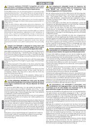
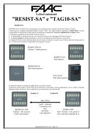
1. Fit the supplied key in the lock, Fig. 21 Ref. , and turn it clockwise as<br />
shown in Fig. 21 Ref. .<br />
2. Turn the release <strong>system</strong> clockwise by about 180°, as shown in Fig. 21 Ref. .<br />
3. Open and close the gate manually.<br />
ENGLISH<br />
Fig. 18<br />
Before sending a pulse, make sure that the gate cannot be moved<br />
manually.<br />
Command a complete gate cycle to check if the travel-limit device is<br />
tripping correctly.<br />
To avoid damaging the operator and/or interrupting operation of<br />
the <strong>automated</strong> <strong>system</strong>, leave a distance of least 40 mm from the<br />
travel limit mechanical stops.<br />
Make sure that at the end of both the opening and closing manoeuvre,<br />
the relevant travel-limit LED stays active (LED OFF).<br />
Make the appropriate modifications to the positions of the travel-limit<br />
magnets.<br />
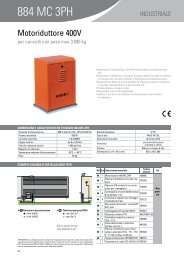
9. RESTORING NORMAL OPERATION MODE<br />
Fig. 21<br />
7. AUTOMATED SYSTEM TEST<br />
Fit the lateral protective devices and re-position the motor cover, securing<br />
it with the appropriate screws (Fig. 19).<br />
To prevent an involuntary pulse from activating the gate during the<br />
manoeuvre, cut power to the <strong>system</strong> before re-locking the operator.<br />
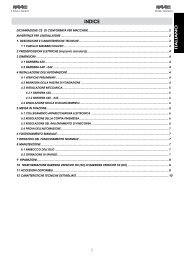
1. Turn the release <strong>system</strong> anti-clockwise by about 180°, as shown in Fig.<br />
22 ref. .<br />
2. Turn the key anti-clockwise, Fig. 22 ref. , and remove it from the lock, as<br />
shown in Fig. 22 ref. .<br />
3. Move the gate until it meshes to release.<br />
Before powering up the <strong>system</strong> again, make sure that the gate cannot<br />
be moved manually.<br />
Fig. 22<br />
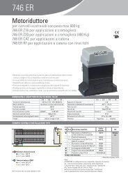
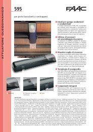
Apply the danger sticker on the top of<br />
the cover (Fig. 20).<br />
Check operating efficiency of the<br />
<strong>automated</strong> <strong>system</strong> and all accessories<br />
connected to it.<br />
Hand the “Use Instructions” to the Customer,<br />
explain correct operation and<br />
use of the gearmotor, and indicate the<br />
potentially dangerous areas of the <strong>automated</strong><br />
<strong>system</strong>.<br />
Fig. 19<br />
Fig. 20<br />
There are no special applications.<br />
10. SPECIAL APPLICATIONS<br />
Anything not expressly specified in these instructions is expressly<br />
prohibited<br />
11. MAINTENANCE<br />
To ensure correct long-term operation and a constant level of safety, we<br />
advise you to generally control the <strong>system</strong> every 6 months. In the “Use Instructions”<br />
booklet, there is a form for recording maintenance jobs.<br />
The enclosed maintenance form is purely a guideline; it cannot be ruled<br />
out that to guarantee a correctly operating <strong>automated</strong> <strong>system</strong> and<br />
a constant level of safety, maintenance operations not described<br />
in this form may be necessary.<br />
12. REPAIRS<br />
The User must not in any way attempt to repair or to take direct action and<br />
must solely contact qualified GENIUS personnel or GENIUS service centres.<br />
13. ACCESSORIES<br />
For accessories, see the GENIUS catalogue.<br />
10