falcon automated system - Faac
falcon automated system - Faac
falcon automated system - Faac

You also want an ePaper? Increase the reach of your titles
YUMPU automatically turns print PDFs into web optimized ePapers that Google loves.
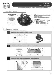
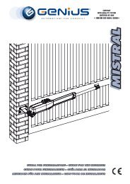
5.4.2. STEEL RACK TO BE SCREWED (FIG. 12)<br />
Manually move the leaf to its opening<br />
position.<br />
Rest the first section of rack on the pinion,<br />
positioning the spacer between the<br />
rack and the edge of the gate. Using<br />
a spirit level, check if the rack is horizontal<br />
and mark the perforation point with a felttipped<br />
pen.<br />
Drill with a 6.5 mm diameter bit, and thread<br />
with an M8 male element. Screw the bolt.<br />
Fig. 12<br />
Manually move the gate, checking if the<br />
rack is resting on the pinion and repeat the operations in point .<br />
Fit another rack element next to the previous one, using a piece of rack, as<br />
shown in Fig. 14 ref. , to synchronise the teeth of the two elements.<br />
Move the gate by hand and perform the securing operations as for<br />
the first element, carrying on like this until you have covered the gate<br />
completely.<br />
Do not allow any superfluous sections of rack to project from the<br />
gate.<br />
6. START-UP<br />
6.1. CONNECTION OF CONTROL BOARD<br />
Before attempting any work on the board (connections, programming,<br />
maintenance), always turn off power.<br />
Observe points 10, 11, 12, 13 and 14 of the GENERAL SAFETY RULES.<br />
Follow the instructions in Fig. 3, route the cables in the raceways and make<br />
the electrical connections to the selected accessories.<br />
Always separate power cables from control and safety cables (push-button,<br />
receiver, photocells, etc.). To prevent any electric noise whatever, use<br />
separate sheaths.<br />
6.1.1. EARTHING<br />
Connect the earthing cable as shown in Fig. 16.<br />
6.1.2. CONTROL UNIT<br />
In the “C” version gearmotors, the electronic control unit is secured to an<br />
adjustable support with a transparent cover.<br />
The board programming push-buttons are located on the cover - this enables<br />
you to program the board without having to remove the cover.<br />
To connect the control unit correctly, follow the specific instructions.<br />
ENGLISH<br />
Fig. 13<br />
6.2. POSITIONING THE TRAVEL-LIMIT ELEMENTS<br />
Fig. 16<br />
To correctly position the travel-limit magnets, the control unit must<br />
first be installed and correctly connected to all the command and<br />
safety accessories.<br />
The operator has a magnetic limit switch, which commands gate motion<br />
to stop when the magnet, which is secured to the upper part of the rack,<br />
activates the sensor. The magnets supplied with the operator are specifically<br />
polarised and activate only one of the sensor’s contacts: the closing or<br />
opening contact. The magnet activating the open gate contact bears an<br />
open padlock symbol, and, vice versa, the magnet activating the closed<br />
gate contact bears the closed padlock symbol (see Fig. 17).<br />
Procedure for correct positioning of the two travel-limit magnets:<br />
Notes on installing the rack<br />
• Make sure that, during gate travel,<br />
all the rack elements do not come<br />
out of the pinion.<br />
• Do not, on any account, weld the<br />
rack elements either to the spacers<br />
or to each other.<br />
• After you have finished installing the<br />
rack, to ensure correct meshing<br />
with the pinion, we advise you to<br />
lower the position of the gearmotor<br />
by about 1.5 mm (Fig.15).<br />
• Manually check if the gate correctly<br />
reaches the travel-limit mechanical<br />
stops and if there is any friction<br />
during travel.<br />
• Do not use grease or other lubricants<br />
between rack and pinion.<br />
Fig. 14<br />
To ensure the operator functions correctly, the magnet showing an<br />
open padlock must be positioned on the left of the operator, looking<br />
at the <strong>automated</strong> <strong>system</strong> from the inside. Vice versa, the magnet<br />
showing a closed padlock must be positioned on the right of the<br />
operator.<br />
Assemble the two magnets as shown in Fig. 17.<br />
Set the operator to manual mode operation - as per paragraph 8 - and<br />
power up the <strong>system</strong>.<br />
Fig. 15<br />
Fig. 17<br />
Manually take the gate to opening position, leaving 4 cm from the travel<br />
limit mechanical stop.<br />
Slide the magnet nearest to the operator on the rack, in the direction of<br />
the motor - see figure 18. As soon as the LED on the board, referring to<br />
the travel limit stop, goes OFF, take the magnet forward by another 10<br />
mm and fasten it with the appropriate screws (Fig. 18 ref. ).<br />
9