falcon automated system - Faac
falcon automated system - Faac
falcon automated system - Faac

Create successful ePaper yourself
Turn your PDF publications into a flip-book with our unique Google optimized e-Paper software.
ENGLISH<br />
5. INSTALLING THE AUTOMATED SYSTEM<br />
5.1. PRELIMINARY CHECKS<br />
To ensure safety and an efficiently operating automatic <strong>system</strong>, make sure<br />
the following conditions are observed:<br />
• The structure of the door must be suitable to be <strong>automated</strong>. Specifically,<br />
the wheel diameter must be in relation to the weight of the gate to be<br />
<strong>automated</strong>; an upper guide must be present; travel-limit mechanical<br />
stops must be fitted to prevent the gate derailing.<br />
• The soil must permit sufficient stability for the foundation plinth.<br />
• There must be no pipes or electrical cables in the plinth excavation<br />
area.<br />
• If the gearmotor is exposed to passing vehicles, install, if possible, adequate<br />
means of protection against accidental impact.<br />
• Check if an efficient earth socket is available for connecting the gearmotor.<br />
• Make sure that there is sufficient space around the operator to enable all<br />
the installation jobs and subsequent maintenance work to be smoothly<br />
carried out.<br />
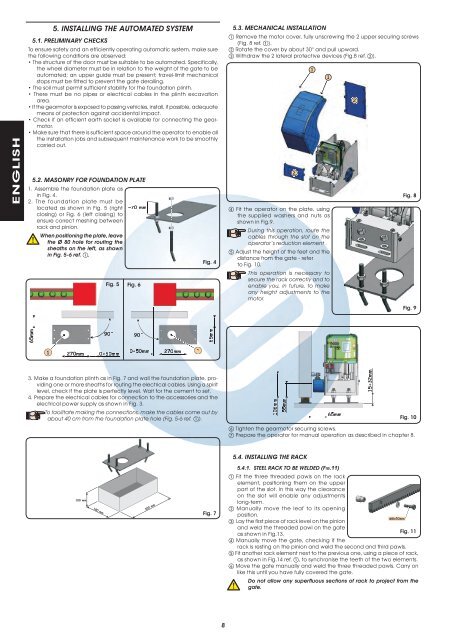
5.2. MASONRY FOR FOUNDATION PLATE<br />
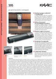
1. Assemble the foundation plate as<br />
in Fig. 4.<br />
2. The foundation plate must be<br />
located as shown in Fig. 5 (right<br />
closing) or Fig. 6 (left closing) to<br />
ensure correct meshing between<br />
rack and pinion.<br />
When positioning the plate, leave<br />
the Ø 80 hole for routing the<br />
sheaths on the left, as shown<br />
in Fig. 5-6 ref. .<br />
Fig. 5 Fig. 6<br />
Fig. 4<br />
5.3. MECHANICAL INSTALLATION<br />
Remove the motor cover, fully unscrewing the 2 upper securing screws<br />
(Fig. 8 ref. ).<br />
Rotate the cover by about 30° and pull upward.<br />
Withdraw the 2 lateral protective devices (Fig.8 ref. ).<br />
Fit the operator on the plate, using<br />
the supplied washers and nuts as<br />
shown in Fig.9.<br />
During this operation, route the<br />
cables through the slot on the<br />
operator’s reduction element .<br />
Adjust the height of the feet and the<br />
distance from the gate - refer<br />
to Fig. 10.<br />
This operation is necessary to<br />
secure the rack correctly and to<br />
enable you, in future, to make<br />
any height adjustments to the<br />
motor.<br />
Fig. 8<br />
Fig. 9<br />
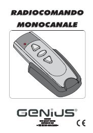
3. Make a foundation plinth as in Fig. 7 and wall the foundation plate, providing<br />
one or more sheaths for routing the electrical cables. Using a spirit<br />
level, check if the plate is perfectly level. Wait for the cement to set.<br />
4. Prepare the electrical cables for connection to the accessories and the<br />
electrical power supply as shown in Fig. 3.<br />
To facilitate making the connections, make the cables come out by<br />
about 40 cm from the foundation plate hole (Fig. 5-6 ref. ).<br />
Fig. 10<br />
Tighten the gearmotor securing screws.<br />
Prepare the operator for manual operation as described in chapter 8.<br />
Fig. 7<br />
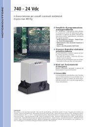
5.4. INSTALLING THE RACK<br />
5.4.1. STEEL RACK TO BE WELDED (FIG.11)<br />
Fit the three threaded pawls on the rack<br />
element, positioning them on the upper<br />
part of the slot. In this way the clearance<br />
on the slot will enable any adjustments<br />
long-term.<br />
Manually move the leaf to its opening<br />
position.<br />
Lay the first piece of rack level on the pinion<br />
and weld the threaded pawl on the gate<br />
as shown in Fig.13.<br />
Fig. 11<br />
Manually move the gate, checking if the<br />
rack is resting on the pinion and weld the second and third pawls.<br />
Fit another rack element next to the previous one, using a piece of rack,<br />
as shown in Fig.14 ref. , to synchronise the teeth of the two elements.<br />
Move the gate manually and weld the three threaded pawls. Carry on<br />
like this until you have fully covered the gate.<br />
Do not allow any superfluous sections of rack to project from the<br />
gate.<br />
8