MENDRISIO - Artemide
MENDRISIO - Artemide
MENDRISIO - Artemide

Create successful ePaper yourself
Turn your PDF publications into a flip-book with our unique Google optimized e-Paper software.
E<br />
G<br />
B<br />
C<br />
D<br />
F<br />
fig. 3<br />
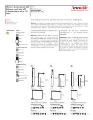
" 3 Eliminare gli inserti di cartone che si trovano nei punti indicati dalle frecce. Negli<br />
stessi punti, all’estremità del gruppo ottico, vi sono delle astine metalliche G che si incastrano<br />
sotto le viti F fissate sulle testate. Sganciarle come descritto in figura. Sollevare il<br />
gruppo ottico ed appoggiarlo leggermente inclinato sopra l’apparecchio. Infilare la testata<br />
B sul supporto C. Inserire il supporto C nel foro posto sul lato dell’apparecchio e bloccarlo<br />
con il dado D. ATTENZIONE: il gambo del supporto C è sagomato per impedire la rotazione<br />
dello stesso e dovrà essere fissato in modo che il foro E sia rivolto verso l’alto. Ripetere la<br />
stessa operazione anche dall’altro lato dell’apparecchio. Riposizionare il gruppo riflettore<br />
all’interno del corpo lampada e rimontare le due astine G.<br />
" 3 Eliminer les éléments en carton, situés dans les points indiqués par les flèches.<br />
Dans ces points, à l’extrémité du groupe optique, se trouvent des tiges métalliques G qui<br />
s’emboîtent au- -dessous des vis F, fixées sur les têtes. Décrocher les tiges comme l’indique<br />
la figure. Lever le groupe optique et l’appuyer légèrement incliné sur l’appareil. Introduire<br />
la tête B dans le support C. Introduire le support C dans le trou qui se trouve sur le côté de<br />
l’appareil et le bloquer au moyen de l’écrou D. ATTENTION: la tige du support C est façonnéedemanièreàempêcherlarotationdecelle--cietdoitêtrefixéedefaçonqueletrouE<br />
se trouve orienté du côté haut. Répeter cette opération même de l’autre côté de l’appareil.<br />
Replacer le groupe réflecteur a l’intérieur du corps de la lampe. Remonter les deux tiges G.<br />
" 3 Remove the cardboard protections shown by the arrows. In the same points at<br />
the end of the optical unit, there are a few metal rods G that lock up under the screws F that<br />
are set on the heads. Remove them as shown in the picture. Lift up the optic unit and lean<br />
against the device in slightly tilting position. Pass the head through the support C. Insert the<br />
support C into the hole on the side of the device and fasten it with the nut D. WARNING: the<br />
shank of the support C is shaped in such a way as to prevent it from rotating and it has to<br />
be fastened in such a way that the hole E is turned upwards. Repeat the same operation also<br />
on the other side of the device. Position the reflector unit inside the lamp again. Install again<br />
the two rods G.<br />
" 3 Die sich in den von den Pfeilen angegebenen Punkten befindenden Einsatzstücke<br />
aus Pappe entfernen. In denselben Punkten, am Ende der optischen Gruppe,<br />
gibt es metallische Stäbe G, die sich unter den Schrauben F einklemmen, die auf den<br />
Köpfen befestigt sind. Sie abhaken, wie im Bild beschrieben. Die optische Einheit aufheben<br />
und sie leicht gegen die Vorrichtung neigen lassen. Den Kopf durch den Halter C durchgehen<br />
lassen. Den Halter C ins Loch an der Seite der Vorrichtung einstecken und ihn mit der<br />
Mutter D befestigen. ACHTUNG: die Schaft vom Halter C ist so gemacht, daß sie nicht umdrehen<br />
kann und sie muß so befestigt werden, daß das Loch E nach oben schaut. Die selbe<br />
Operation auch an der anderen Seite der Vorrichtung wiederholen. Den Reflektor in die<br />
Lampe wieder einstecken. Die beiden Stäbe G wieder einbauen.<br />
" 3 Eliminar los insertos de cartón que se encuentra en los puntos indicados por las<br />
flechas. En estos mismos puntos, a la extremidad del grupo óptico, se presentan pequeñas<br />
pértigas metálicas G che se embarbillan bajo los tornillos F sobre las cabezas. Desengancharlas<br />
como viene explicado en la figura. Levantar el grupo óptico y apoyarlo un poco inclinado<br />
sobre el aparato. Introducir el cabezal B en el soporte C. Introducir el soporte C en<br />
el orificio que se encuentra en el lado del aparato y bloquearlo con la tuerca D. ATENCION:<br />
el vástago del soporte C es moldeado para contrastar la rotación de ello y se debe fijar de<br />
forma que el orificio E se encuentre hacia lo alto. Repetir la misma operación también en<br />
el otro lado del aparato. Volve a colocar el grupo reflector al interior del cuerpo lámpara.<br />
Volver a montar las dos pequeñas pértigas.<br />
A<br />
A<br />
B<br />
fig. 4<br />
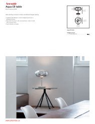
" 4 Inserire le lampadine. Rimontare la parte superiore dell’apparecchio<br />
ripetendo al contrario i punti 2- -1 del presente foglio istruzioni, fino ad arrivare a<br />
rimontare le due viti A che fissano la testata B.Sesidesideracollegaredueopiù<br />
moduli ”<strong>MENDRISIO</strong>”, utilizzare l’apposito supporto fissato con i suoi dadi in<br />
dotazione.<br />
" 4 Introduire les douilles. Remonter la partie supérieure de l’appareil en effectuant<br />
les opérations des points 2 et 1 des instructions, au contraire, jusqu’à remonter<br />
les deux vis A qui fixent la tête B.<br />
" 4 Insert the bulbs. Assemble the upper part of the device repeating the operation<br />
in the opposite sequence from point 2 to 1 of this instruction leaflet, till you<br />
insert the two screws fastening the head B.<br />
" 4 Die Glühlampen einstecken. Die obere Seite der Vorrichtung montieren,<br />
und dazu die Punkten von 2 bis 1 in dieser Anweisungsseite folgen, bis die zwei<br />
Schrauben eingesteckt sind und Kopf B befestigt ist.<br />
" 4 Introducir las bombillas. Volver a montar la parte superior del aparato<br />
efectuando las operaciones de los puntos 2 y 1 de las instrucciones, al contrario,<br />
hasta volver a montar los dos tornillos A que fijan el cabezal B.<br />
H<br />
M<br />
D<br />
O<br />
P<br />
fig. 5<br />
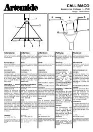
" 5 SOSPENSIONE CON ALIMENTAZIONE. Separare il fondello H dal rosone<br />
M. Fissare il fondello H al soffitto mediante le due asole poste sullo stesso. Eseguire i<br />
collegamenti elettrici all’apposito morsetto. Agganciare il cavetto di sostegno D con il<br />
fermacavo metallico O al gancio P. Allentare le due viti del fermacavo O eregolarel’altezza<br />
dell’apparecchio. Rimontare il rosone M con una leggera pressione. Il cavo elettrico<br />
dovrà essere infilato nell’asola indicata dalla freccia. Il modulo mendrisio dovtà<br />
essere quindi appeso con questa asola di entrata cavi in corrispondenza del rosone di<br />
alimentazione.<br />
" 5 SOSPENSIONE (LAMPE A SUSPENSION) AVEC ALIMENTATION. Séparer<br />
la plaque de fixation H de la rosace M.FixerlaplaqueH au plafond au moyen des<br />
oeillets qui se trouvent sur elle. Effectuer les connexions électriques à la borne. AccrocherlecâbledesoutienD<br />
au moyen dupresse- -câble métallique O aucrochet P. Dévisser<br />
les deux vis du presse- -câble O et régler la hauteur de l’appareil. Remonter la rosace M<br />
avec une légère pression.<br />
" 5 SUSPENSION WITH POWER SUPPLY. Divide the bottom H from the rosette<br />
M. Tighten the bottom H against the ceiling through its two slots. Make all electrical connectionsof<br />
the corresponding terminal.Hook the support cable D witha metallic cable- -<br />
fastener O to the hook P. Loose the two screws of the cable- -fastener O and regulate the<br />
height of the device. Assemble the rosette M again with a slight pressure.<br />
" 5 AUFHÄNGUNG MIT STROMZUFUHR. Die Bodenscheibe H von der Deckenrosette<br />
M trennen. Die Bodenscheibe H gegen die Decke durch die zwei Löcher befestigen.Alle<br />
elektrische Anschlüsse durchführen.Das Haltekabel D mit der metallischen Kabelbefestigung<br />
O am Haken P blockieren. Die zwei Schrauben von der Kabelbefestigung<br />
O ausdrehen und die Höhe der Vorrichtung einstellen. Die Deckenrosette M mit<br />
einem leichten Druck wieder montieren.<br />
" 5 SOSPENSIONE (LAMPARA DE SUSPENSION) CON ALIMENTACION.<br />
Separar la placa de fijación H del rosetón M. Fijar la placa H al techo mediante los dos<br />
ojales que se encuentran en ella. Efectuar las conexiones eléctricas al borne. Enganchar<br />
elcabledesosténD con el prensa- -cables metálico O al gancho P. Aflojar los dos tornillos<br />
del prensa- -cables O y ajustar la altura del aparato.Volver a montar el rosetón M con<br />
una ligera presión.