MENDRISIO - Artemide
MENDRISIO - Artemide
MENDRISIO - Artemide

You also want an ePaper? Increase the reach of your titles
YUMPU automatically turns print PDFs into web optimized ePapers that Google loves.
Istruzioni di montaggio<br />
Instructions de montage<br />
Assembly instructions<br />
Montageanleitung<br />
Instrucciones para el montaje<br />
<strong>MENDRISIO</strong><br />
Apparecchio in classe I - - IP 20<br />
Design: Mario Botta - - Dante Solcá<br />
Avvertenze:<br />
Prima di ogni operazione sull’apparecchio<br />
disinserire la tensione di<br />
rete.<br />
Attenzione:<br />
Usare esclusivamente le lampadine<br />
del tipo e potenza indicate nei<br />
dati di targa.<br />
La sicurezza elettrica dell’apparecchio<br />
è garantita con l’uso appropriato<br />
delle seguenti istruzioni. Pertanto<br />
è necessario conservarle.<br />
Per garantire la massima protezione<br />
dell’apparecchio,<br />
<strong>MENDRISIO</strong> éricopertodaunfilm<br />
protettivo che deve essere rimosso<br />
dopo l’installazione.<br />
All’interno dell’apparecchio e tra le<br />
fessure superiori del corpo lampada<br />
vi sono degli inserti in cartone<br />
che devono essere rimossi<br />
durante l’installazione.<br />
Avis:<br />
Déconnecter la tension deréseau<br />
avant toute opération sur l’appareil.<br />
Attention:<br />
Employer exsclusivement les<br />
ampoules du type et de la puissance<br />
indiqués sur la plaque de<br />
l’appareil.<br />
La sécurité de l’appareil n’est<br />
garantie que si les instructions suivantes<br />
sont convenablement suivies.<br />
Il est donc nécessaire de les<br />
conserver.<br />
Pour assurer une protection optimale<br />
de l’appareil <strong>MENDRISIO</strong>,ce<br />
dernier est recouvert d’un film de<br />
protection qui ne doit être enlevé<br />
qu’après son installation. A l’intérieur<br />
de l’appareil et dans les fentes<br />
supérieures du corps de la lampe se<br />
trouvent des éléments en carton qui<br />
doivent être enlevés lors de l’installation<br />
de l’appareil.<br />
Note:<br />
Prior to any work on the fixture<br />
always switch off the mains.<br />
Attention:<br />
Only use bulbs of the type and wattage<br />
indicated on the rating plate.<br />
This equipment is guaranteed only<br />
when used as indicated in the following<br />
instructions. Therefore they<br />
should be kept for future reference.<br />
In order to ensure the best protection<br />
of the appliance, <strong>MENDRISIO</strong><br />
is covered with a light- - protective<br />
film which must be removed after<br />
installation. Inside the appliance<br />
and in the upper slots of the main<br />
partoftheappliancetherearesome<br />
cardboard protections which must<br />
be removed during installation.<br />
Vorsicht:<br />
Von jeidem Eingriff am dem Gerät<br />
die Netzspanung unterbrechen.<br />
Achtung:<br />
Ausschließlich Lampen verwenden,<br />
die dem auf dem auf dem Geräteschild<br />
angegebenen Typ und Wert<br />
entsprechen.<br />
Die Sicherheit der Leuchte wird nur<br />
bei sachgerechtem Gebrauch<br />
gemäß folgenden Anweisungen<br />
gewährleistet. Bitte bewahren Sie<br />
diese sorgfälting auf.<br />
Um den höchsten Schutz des<br />
Geräts zu garantieren, ist MENDRI-<br />
SIO von einem hell Schutzfilm bedeckt,<br />
der nach der Installation entfernt<br />
werden soll. Im Innern des<br />
Geräts und zwischen den oberen<br />
Schlitzen des Lampenkörpers gibt<br />
es Einsatzstücke aus Pappe, die<br />
während der Installation entfernt<br />
werden sollen.<br />
Advertencia:<br />
Desconectar la tensiónde red antes<br />
de cualquier operación sobre el<br />
aparato.<br />
Atención:<br />
Utilizar exclusivamente las bombillas<br />
del tipo y potencia indicados en<br />
la placa del aparado.<br />
La seguridad del aparato está<br />
garantizada solo con el uso apropriado<br />
de las instrucciones. Por lo<br />
tanto es necesario conservarlas.<br />
Para garantizar la máxima protección<br />
del aparato, <strong>MENDRISIO</strong><br />
viene revestido con un film protectivoquedebeserremovidodespués<br />
de la instalación. Al interno del aparato<br />
y entre las tres ranuras superiores<br />
del cuerpo de la lámpara se<br />
presentan insertos de cartón que<br />
deben ser removidos durante la<br />
instalación.<br />
Lampadine:<br />
2x28W T5 (G5)<br />
2x35W T5 (G5)<br />
Ampoules:<br />
2x28W T5 (G5)<br />
2x35W T5 (G5)<br />
Bulbs:<br />
2x28W T5 (G5)<br />
2x35W T5 (G5)<br />
Glühlampen:<br />
2x28W T5 (G5)<br />
2x35W T5 (G5)<br />
Bombillas:<br />
2x28W T5 (G5)<br />
2x35W T5 (G5)<br />
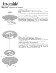
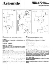
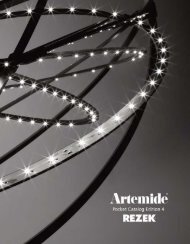
fig. 1<br />
A<br />
B<br />
A<br />
" 1 SvitareleduevitiA , utilizzando la chiave in dotazione, e rimuovere la<br />
testata B. Per poter eseguire questa operazione utilizzare se necessario un cacciavite<br />
o la stessa chiave a brugola spingendo nel punto indicato dalla freccia.<br />
ATTENZIONE: eseguire questa operazione ad entrambe le estremità<br />
dell’apparecchio.<br />
" 1 Dévisser les deux vis A, en utilisant la clé fournie, et ôter la tête B.Pour<br />
effectuer cette opération utiliser, si nécessaire, un tournevis ou la même clé hexagonale<br />
en poussant vers le point indiqué par la flèche. ATTENTION: exécuter<br />
cette opération sur les deux extrémités de l’appareil.<br />
" 1 Unscrew the two screws A with the key supplied and remove the head<br />
B . To carry out this operation you need to use, if necessary, a screwdriver or the<br />
same socket head key pushing into the point indicated by the arrow. ATTEN-<br />
TION: This operation must be performed on both ends of the device.<br />
" 1 Die zwei Schrauben A mit den mitgelieferten Schlüsseln ausdrehen<br />
und den Kopf B entfernen. Um diese Operation durchzuführen, brauchen Sie,<br />
wenn notwendig, einen Schraubenzieher oder den selben Sechskantenschlüssel,<br />
und in den mit dem Pfeil angegebenen Punkt einzuschieben.<br />
VORSICHT: Führen Sie diese Operation a beiden Enden des Geräts aus.<br />
" 1 Destornillar los dos tornillos A, utilizando la llave que se suministra,<br />
y quitar el cabezal B. Para efectuar esta operación utilizar, si necesario, un destornillador<br />
o la misma llave hexagonal empujando en el punto indicado por la<br />
flecha. ATENCION: ejecutar esta operación en ambas las extremidades del<br />
aparato.<br />
fig. 2 " 2 Sollevare verso l’alto la parte superiore dell’apparecchio. Appoggiarla<br />
a fianco del corpo illuminante.<br />
" 2 Lever en haut la partie superieure de l’appareil. L’appuyer à côté du<br />
corps éclairant.<br />
" 2 Lift up the upper part of the cover. Lean it against the lamp body.<br />
" 2 Die obere Seite vom Deckel aufheben. Den Kopf gegen den<br />
Lichtkörper anlehnen.<br />
" 2 Levantar hacia lo alto la parte superior del aparato. Apoyarla al lado<br />
del cuerpo iluminante.
E<br />
G<br />
B<br />
C<br />
D<br />
F<br />
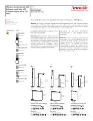
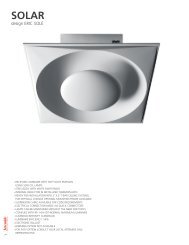
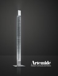
fig. 3<br />
" 3 Eliminare gli inserti di cartone che si trovano nei punti indicati dalle frecce. Negli<br />
stessi punti, all’estremità del gruppo ottico, vi sono delle astine metalliche G che si incastrano<br />
sotto le viti F fissate sulle testate. Sganciarle come descritto in figura. Sollevare il<br />
gruppo ottico ed appoggiarlo leggermente inclinato sopra l’apparecchio. Infilare la testata<br />
B sul supporto C. Inserire il supporto C nel foro posto sul lato dell’apparecchio e bloccarlo<br />
con il dado D. ATTENZIONE: il gambo del supporto C è sagomato per impedire la rotazione<br />
dello stesso e dovrà essere fissato in modo che il foro E sia rivolto verso l’alto. Ripetere la<br />
stessa operazione anche dall’altro lato dell’apparecchio. Riposizionare il gruppo riflettore<br />
all’interno del corpo lampada e rimontare le due astine G.<br />
" 3 Eliminer les éléments en carton, situés dans les points indiqués par les flèches.<br />
Dans ces points, à l’extrémité du groupe optique, se trouvent des tiges métalliques G qui<br />
s’emboîtent au- -dessous des vis F, fixées sur les têtes. Décrocher les tiges comme l’indique<br />
la figure. Lever le groupe optique et l’appuyer légèrement incliné sur l’appareil. Introduire<br />
la tête B dans le support C. Introduire le support C dans le trou qui se trouve sur le côté de<br />
l’appareil et le bloquer au moyen de l’écrou D. ATTENTION: la tige du support C est façonnéedemanièreàempêcherlarotationdecelle--cietdoitêtrefixéedefaçonqueletrouE<br />
se trouve orienté du côté haut. Répeter cette opération même de l’autre côté de l’appareil.<br />
Replacer le groupe réflecteur a l’intérieur du corps de la lampe. Remonter les deux tiges G.<br />
" 3 Remove the cardboard protections shown by the arrows. In the same points at<br />
the end of the optical unit, there are a few metal rods G that lock up under the screws F that<br />
are set on the heads. Remove them as shown in the picture. Lift up the optic unit and lean<br />
against the device in slightly tilting position. Pass the head through the support C. Insert the<br />
support C into the hole on the side of the device and fasten it with the nut D. WARNING: the<br />
shank of the support C is shaped in such a way as to prevent it from rotating and it has to<br />
be fastened in such a way that the hole E is turned upwards. Repeat the same operation also<br />
on the other side of the device. Position the reflector unit inside the lamp again. Install again<br />
the two rods G.<br />
" 3 Die sich in den von den Pfeilen angegebenen Punkten befindenden Einsatzstücke<br />
aus Pappe entfernen. In denselben Punkten, am Ende der optischen Gruppe,<br />
gibt es metallische Stäbe G, die sich unter den Schrauben F einklemmen, die auf den<br />
Köpfen befestigt sind. Sie abhaken, wie im Bild beschrieben. Die optische Einheit aufheben<br />
und sie leicht gegen die Vorrichtung neigen lassen. Den Kopf durch den Halter C durchgehen<br />
lassen. Den Halter C ins Loch an der Seite der Vorrichtung einstecken und ihn mit der<br />
Mutter D befestigen. ACHTUNG: die Schaft vom Halter C ist so gemacht, daß sie nicht umdrehen<br />
kann und sie muß so befestigt werden, daß das Loch E nach oben schaut. Die selbe<br />
Operation auch an der anderen Seite der Vorrichtung wiederholen. Den Reflektor in die<br />
Lampe wieder einstecken. Die beiden Stäbe G wieder einbauen.<br />
" 3 Eliminar los insertos de cartón que se encuentra en los puntos indicados por las<br />
flechas. En estos mismos puntos, a la extremidad del grupo óptico, se presentan pequeñas<br />
pértigas metálicas G che se embarbillan bajo los tornillos F sobre las cabezas. Desengancharlas<br />
como viene explicado en la figura. Levantar el grupo óptico y apoyarlo un poco inclinado<br />
sobre el aparato. Introducir el cabezal B en el soporte C. Introducir el soporte C en<br />
el orificio que se encuentra en el lado del aparato y bloquearlo con la tuerca D. ATENCION:<br />
el vástago del soporte C es moldeado para contrastar la rotación de ello y se debe fijar de<br />
forma que el orificio E se encuentre hacia lo alto. Repetir la misma operación también en<br />
el otro lado del aparato. Volve a colocar el grupo reflector al interior del cuerpo lámpara.<br />
Volver a montar las dos pequeñas pértigas.<br />
A<br />
A<br />
B<br />
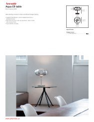
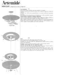
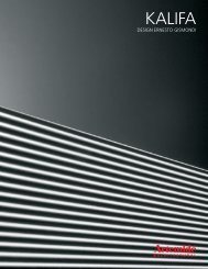
fig. 4<br />
" 4 Inserire le lampadine. Rimontare la parte superiore dell’apparecchio<br />
ripetendo al contrario i punti 2- -1 del presente foglio istruzioni, fino ad arrivare a<br />
rimontare le due viti A che fissano la testata B.Sesidesideracollegaredueopiù<br />
moduli ”<strong>MENDRISIO</strong>”, utilizzare l’apposito supporto fissato con i suoi dadi in<br />
dotazione.<br />
" 4 Introduire les douilles. Remonter la partie supérieure de l’appareil en effectuant<br />
les opérations des points 2 et 1 des instructions, au contraire, jusqu’à remonter<br />
les deux vis A qui fixent la tête B.<br />
" 4 Insert the bulbs. Assemble the upper part of the device repeating the operation<br />
in the opposite sequence from point 2 to 1 of this instruction leaflet, till you<br />
insert the two screws fastening the head B.<br />
" 4 Die Glühlampen einstecken. Die obere Seite der Vorrichtung montieren,<br />
und dazu die Punkten von 2 bis 1 in dieser Anweisungsseite folgen, bis die zwei<br />
Schrauben eingesteckt sind und Kopf B befestigt ist.<br />
" 4 Introducir las bombillas. Volver a montar la parte superior del aparato<br />
efectuando las operaciones de los puntos 2 y 1 de las instrucciones, al contrario,<br />
hasta volver a montar los dos tornillos A que fijan el cabezal B.<br />
H<br />
M<br />
D<br />
O<br />
P<br />
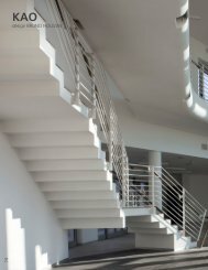
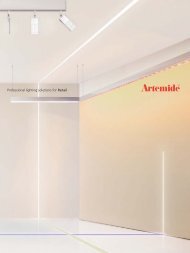
fig. 5<br />
" 5 SOSPENSIONE CON ALIMENTAZIONE. Separare il fondello H dal rosone<br />
M. Fissare il fondello H al soffitto mediante le due asole poste sullo stesso. Eseguire i<br />
collegamenti elettrici all’apposito morsetto. Agganciare il cavetto di sostegno D con il<br />
fermacavo metallico O al gancio P. Allentare le due viti del fermacavo O eregolarel’altezza<br />
dell’apparecchio. Rimontare il rosone M con una leggera pressione. Il cavo elettrico<br />
dovrà essere infilato nell’asola indicata dalla freccia. Il modulo mendrisio dovtà<br />
essere quindi appeso con questa asola di entrata cavi in corrispondenza del rosone di<br />
alimentazione.<br />
" 5 SOSPENSIONE (LAMPE A SUSPENSION) AVEC ALIMENTATION. Séparer<br />
la plaque de fixation H de la rosace M.FixerlaplaqueH au plafond au moyen des<br />
oeillets qui se trouvent sur elle. Effectuer les connexions électriques à la borne. AccrocherlecâbledesoutienD<br />
au moyen dupresse- -câble métallique O aucrochet P. Dévisser<br />
les deux vis du presse- -câble O et régler la hauteur de l’appareil. Remonter la rosace M<br />
avec une légère pression.<br />
" 5 SUSPENSION WITH POWER SUPPLY. Divide the bottom H from the rosette<br />
M. Tighten the bottom H against the ceiling through its two slots. Make all electrical connectionsof<br />
the corresponding terminal.Hook the support cable D witha metallic cable- -<br />
fastener O to the hook P. Loose the two screws of the cable- -fastener O and regulate the<br />
height of the device. Assemble the rosette M again with a slight pressure.<br />
" 5 AUFHÄNGUNG MIT STROMZUFUHR. Die Bodenscheibe H von der Deckenrosette<br />
M trennen. Die Bodenscheibe H gegen die Decke durch die zwei Löcher befestigen.Alle<br />
elektrische Anschlüsse durchführen.Das Haltekabel D mit der metallischen Kabelbefestigung<br />
O am Haken P blockieren. Die zwei Schrauben von der Kabelbefestigung<br />
O ausdrehen und die Höhe der Vorrichtung einstellen. Die Deckenrosette M mit<br />
einem leichten Druck wieder montieren.<br />
" 5 SOSPENSIONE (LAMPARA DE SUSPENSION) CON ALIMENTACION.<br />
Separar la placa de fijación H del rosetón M. Fijar la placa H al techo mediante los dos<br />
ojales que se encuentran en ella. Efectuar las conexiones eléctricas al borne. Enganchar<br />
elcabledesosténD con el prensa- -cables metálico O al gancho P. Aflojar los dos tornillos<br />
del prensa- -cables O y ajustar la altura del aparato.Volver a montar el rosetón M con<br />
una ligera presión.
V<br />
D<br />
R<br />
Q<br />
S<br />
fig. 6<br />
R<br />
T<br />
" 6 SOSPENSIONE SENZA ALIMENTAZIONE. Fissare con un tassello ad<br />
espansione il particolare Q al soffitto. Far passare il cavetto di sostegno D nel particolare<br />
R ed infilare l’estremità nel foro laterale del particolare Q. Avvitare il particolare R al particolare<br />
Q. Tirare l’estremità del cavetto D fino a che l’apparecchio non sia perfettamente<br />
orizzontale. AVVERTENZA: per poter far scorrere verso il basso il cavetto D si deve spingere<br />
verso l’alto la parte terminale S del particolare R. Montare il cono di copertura T.<br />
È possibile regolare la luce indiretta facendo scorrere il profilo interno mediante l’inserto<br />
in dotazione. Avvitare l’inserto V nella boccola indicata e regolare l’apertura delle asole<br />
agendo nel senso indicato.<br />
" 6 SOSPENSIONE (LAMPE A SUSPENSION) AVEC ALIMENTATION. Fixer<br />
au moyen d’une vis tamponnée la pièce Q au plafond. Faire passer le câble de soutien<br />
D dans la pièce R et introduire l’extrémité dansle troulatéral de la pièce Q. Visser la pièce<br />
R àlapièceQ.Tirer l’extrémité du câble D jusqu’à quand l’appareil soit parfaitement horizontal.<br />
AVERTISSEMENT: pour faire glisser en bas le câble D pousser du côté haut la<br />
partie terminale S de la pièce R. Monter le cône de couverture T. Il est possible de régler<br />
la lumière indirecte, en faisant glisser le profil interne à l’aide de l’élément fourni. Serrer<br />
l’élément V dans la bague indiquée et régler l’ouverture, en agissant dans le sens indiqué.<br />
" 6 SUSPENSION WITHOUT POWER SUPPLY. Fasten detail Q with a screw anchor<br />
on the ceiling. Pass the support cable D through detail R and insert one end into<br />
thesideholeofdetailQ.ScrewdetailR withdetail Q. Pull the end of cable D till the device<br />
is perfectly horizontal. WARNING: in order to have the cable D sliding downwards, push<br />
upwards the terminal part S of detail R. Assemble the covering cone T. Youcanadjust<br />
the indirect light by sliding the internal profile with the supplied accessory. Screw in the<br />
accessory V into the bushing as shown, adjust the opening of the slots by turning it as<br />
shown.<br />
" 6 AUFHÄNGUNG OHNE STROMZUFUHR. Detail Q mit einem Dübel an der<br />
Decke befestigen. Das Haltekabel D durch Detail R durchgehen lassen und ein Ende in<br />
dasSeitenlochvom Detail Q einstecken..Detail R mit Detail Q zusammenschrauben. Ein<br />
Ende vom Kabel D ziehen, bis die Vorrichtung perfekt waagrecht ist. ACHTUNG: um in<br />
der Lage zu sein, das Kabel D nach unten durchgehen lassen, das Ende S vom Detail<br />
R nach oben schieben.Den Kegel T montieren. Es ist möglich, das indirekte Licht einzustellen,<br />
indem man das innere Profil mittels des Einsatzstücks in Ausstattung gleiten läßt.<br />
Das Einsatzstück V in die angegebene Büchse anschrauben, und die Öffnung der Ösen<br />
einstellen, indem man in der angegebenen Richtung wirkt.<br />
" 6 SOSPENSIONE (LAMPARA DE SUSPENSION) SIN ALIMENTACION. Fijar<br />
con una cuña de expansión la pieza Q al techo. Hacer pasar el cable de sostén D en la<br />
pieza R e introducir la extremidad en el orificio lateral de la pieza Q. Atornillar la pieza<br />
R alapiezaQ. Tirar la extremidad del cable D hasta cuando el aparato no se encuentra<br />
en posición perfectamente horizontal. ADVERTENCIA: parahacerdeslizarhacialo<br />
bajo el cable D empujar hacia lo alto la parte terminal S de la pieza R. Montar el cono<br />
de cobertura T. Es posible regular la luz indirecta haciendo deslizar el pérfil interno mediante<br />
el inserto en dotación. Entornillar el inserto V en el casquillo y regular la apertura<br />
de las tuercas en el sentido indicado.<br />
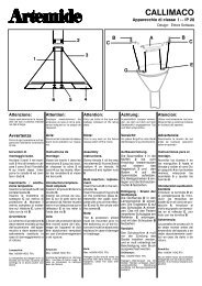
fig. 7a<br />
K<br />
K<br />
fig. 7b<br />
K<br />
K<br />
W<br />
W<br />
K<br />
K<br />
W<br />
W<br />
fig. 7c<br />
fig. 7d
Collegamenti elettrici.<br />
I collegamenti elettrici alle<br />
morsettiere di alimentazione devono<br />
essere cosi’ realizzati:<br />
ELETTRONICO<br />
NON<br />
DIMMERABILE (fig. 7a)<br />
Collegare ad una delle due<br />
morsettiere K ,aipoliN,1e ,la<br />
linea di alimentazione ordinaria.<br />
ELETTRONICO DIMMERABILE<br />
(fig. 7b)<br />
Collegare ad una delle due<br />
morsettiere K ,aipoliN,1e ,la<br />
linea di alimentazione ordinaria.<br />
Collegare ai poli 1 e 2 di una delle due<br />
morsettiere W, i poli + e - - del<br />
dimmer.<br />
EMERGENZA NON DIMMERABILE<br />
(fig. 7b)<br />
Collegare ad una delle due<br />
morsettiere K ,aipoliN,1e ,la<br />
linea di alimentazione ordinaria.<br />
Collegare ai poli N e 3 di una delle<br />
due morsettiere W , la linea non<br />
interrotta per l’alimentazione di<br />
emergenza. Le fasi 1 e 3 sono linee<br />
separate di medesima fase.<br />
EMERGENZA DIMMERABILE (fig.<br />
7b)<br />
Collegare ad una delle due<br />
morsettiere K ,aipoliN,1e ,la<br />
linea di alimentazione ordinaria.<br />
Collegare ai poli N e 3 di una delle<br />
due morsettiere W , la linea non<br />
interrotta per l’alimentazione di<br />
emergenza. Collegare ai poli 1 e 2 di<br />
una delle due morsettiere W, ipoli+<br />
e--deldimmer.Lefasi1e3sono<br />
linee separate di medesima fase.<br />
TUTTELEVERSIONI:<br />
Nel caso si colleghino piu’ moduli<br />
mendrisio occorre collegare tra loro<br />
le morsettiere dei moduli adiacenti ,<br />
come indicato in figura 7c. Devono<br />
essere collegate tra loro le<br />
morsettiere K con Ke,enelcasoci<br />
fossero, le morsettiere W con W.<br />
Il cavo elettrico che proviene dal<br />
soffitto dovrà essere sguainato prima<br />
dell’entrata dell’apposito pressacavo<br />
(fig. 7d).<br />
Connexions électriques.<br />
Les connexions électriques aux<br />
boîtes aux bornes d’alimentation<br />
doivent être réalisées de la façon suivante:<br />
ELECTRONIQUE SANS REGLAGE<br />
D’INTENSITE LUMINEUSE (fig.7a)<br />
Relier la ligne d’alimentation ordinaire<br />
à l’une des deux boîtes aux<br />
bornes K, aux pôles N. 1 et .<br />
ELECTRONIQUE AVEC REGLAGE<br />
D’INTENSITE LUMINEUSE (fig.7b)<br />
Relier la ligne d’alimentation ordinaire<br />
à l’une des deux boîtes aux<br />
bornes K, aux pôles N. 1 et . Relier<br />
ensuite les pôles + et - - du régulateur<br />
d’intensité lumineuse aux pôles 1 et 2<br />
de l’une des deux boîtes aux bornes<br />
W.<br />
URGENCE SANS REGLAGE D’IN-<br />
TENSITE LUMINEUSE (fig.7b)<br />
Relier la ligne d’alimentation ordinaire<br />
à l’une des deux boîtes aux<br />
bornes K, aux pôles N. 1 et . Relier<br />
ensuite la ligne continue pour l’alimentation<br />
d’urgence aux pôles N et 3<br />
de l’une des deux boîtes aux bornes<br />
W. Les phases 1 et 3 représentent des<br />
lignes séparées d’une même phase.<br />
URGENCE AVEC REGLAGE D’IN-<br />
TENSITE LUMINEUSE (fig.7b)<br />
Relier la ligne d’alimentation ordinaire<br />
à l’une des deux boîtes aux<br />
bornes K, aux pôles N. 1 et .<br />
Relier ensuite la ligne continue pour<br />
l’alimentation d’urgence aux pôles N<br />
et 3 de l’une des deux boîtes aux<br />
bornes W. Relier les pôles + et - - du<br />
régulateur d’intensité lumineuse aux<br />
pôles 1 et 2 de l’une des deux boîtes<br />
aux bornes W. Les phases 1 et 3 représentent<br />
des lignes séparées d’une<br />
même phase.<br />
TOUTES LES VERSIONS<br />
En cas de connexion de plusieurs appareils<br />
<strong>MENDRISIO</strong>, connecter réciproquement<br />
les boîtes aux bornes<br />
des modules voisins comme l’indique<br />
la figure 7c. Relier entre elles les<br />
boîtes aux bornes K et, si elles existent,<br />
les boîtes aux bornes W.<br />
Wiring:<br />
The wires must be connected to the<br />
power supply terminal block as follows:<br />
ELECTRONIC, NO DIMMER (fig.<br />
7a)<br />
Connect the normal power supply<br />
line to the terminals N, 1 and of<br />
one of the two terminal blocks K.<br />
ELECTRONIC, WITH DIMMER (fig.<br />
7b)<br />
Connect the normal power supply<br />
line to the terminals N, 1 and of<br />
one of the two terminal blocks K.<br />
Connect to the terminals 1 and 2 of<br />
one of the two terminal blocks W, the<br />
terminals + and - - of the dimmer.<br />
EMERGENCY, NO DIMMER (fig.<br />
7b)<br />
Connect the normal power supply<br />
line to the terminals N, 1 and of<br />
one of the two terminal blocks K.<br />
Connect to the terminals N and 3 of<br />
one of the two blocks W the uninterrupted<br />
line for emergency power<br />
supply. The phases 1 and 3 are separated<br />
lines with the same phase.<br />
ELECTRONIC, WITH DIMMER (fig.<br />
7b)<br />
Connect the normal power supply<br />
line to the terminals N, 1 and of<br />
one of the two terminal blocks K.<br />
Connect to the terminals N and 3 of<br />
one of the two blocks W the uninterrupted<br />
line for emergency power<br />
supply. Connect to the terminals 1<br />
and 2 of one of the two terminal<br />
blocks W the terminals + and - - of<br />
thedimmer.Thephases1and3are<br />
separated lines with the same phase.<br />
ALL VERSIONS<br />
In case several Mendrisio unit are<br />
connected, adjacent units terminal<br />
blocks must be connected as shown<br />
in the picture 7c. The terminal blocks<br />
K must be connected to the terminal<br />
blocks K and the terminal blocks W,<br />
if any, to the terminal blocks W.<br />
Elektrische Verbindungen.<br />
Die elektrischen Verbindungen an den<br />
Versorgungsklemmenbrettern<br />
müssen wie folgt durchgeführt werden:<br />
NICHT MIT DIMMER EINSTELL-<br />
BARES ELEKTRONISCHES GERÄT<br />
(Bild 7a)<br />
An einem der beiden Klemmenbretter<br />
K, an den Polen N, 1 und die allgemeine<br />
Versorgungslinie verbinden.<br />
MIT DIMMER EINSTELLBARES<br />
ELEKTRONISCHES GERÄT (Bild<br />
7b)<br />
An einem der beiden Klemmenbretter<br />
K, an den Polen N, 1 und die allgemeine<br />
Versorgungslinie verbinden. An<br />
den Polen 1 und 2 von einem der beiden<br />
Klemmenbretter W die Pole + und<br />
- - des Dimmers verbinden.<br />
NICHT MIT DIMMER EINSTELL-<br />
BARE NOTFALLVORRICHTUNG<br />
(Bild 7b)<br />
An einem der beiden Klemmenbretter<br />
K, an den Polen N, 1 und die<br />
allgemeine Versorgungslinie verbinden.<br />
An den Polen N und 3 von einem<br />
der beiden Klemmenbretter W die<br />
nicht unterbrochene Linie für die Notfallversorgung<br />
verbinden. Die Phasen<br />
1 und 3 sind getrennte Linien gleicher<br />
Phase.<br />
MIT DIMMER EINSTELLBARE NOT-<br />
FALLVORRICHTUNG (Bild 7b)<br />
An einem der beiden Klemmenbretter<br />
K, an den Polen N, 1 und die<br />
allgemeine Versorgungslinie verbinden.<br />
An den Polen N und 3 von einem<br />
der beiden Klemmenbretter W die<br />
nicht unterbrochene Linie für die Notfallversorgung<br />
verbinden. An den Polen<br />
1 und 2 von einem der beiden<br />
KlemmenbretterWdiePole+und--<br />
des Dimmers verbinden. Die Phasen 1<br />
und 3 sind getrennte Linien gleicher<br />
Phase.<br />
ALLE AUSFÜHRUNGEN<br />
Wenn man mehrere Mendrisio- -Module<br />
verbindet, muß man die Klemmenbretter<br />
der naheliegenden Module miteinander<br />
verbinden, wie im Bild 7c<br />
angegeben. Die Klemmenbretter K mit<br />
K müssen miteinander verbunden<br />
werden, und, wenn sie anwesend<br />
sind, die Klemmenbretter W mit W.<br />
Conexiones eléctricas.<br />
Lasconexioneseléctricasalosterminales<br />
de alimentación deben ser realizados<br />
de la siguiente manera:<br />
ELÉCTRONICO DE INTENSIDAD<br />
NO REGULABLE (Fig. 7a)<br />
Conectar a una de los dos terminales<br />
de alimentación K, a los polos N. 1 y<br />
, la línea de alimentación<br />
ordinaria.<br />
ELÉCTRONICO DE INTENSIDAD<br />
REGULABLE (Fig. 7b)<br />
Conectar a una de los dos terminales<br />
de alimentación K, a los polos N. 1 y<br />
, la línea de alimentación ordinaria.<br />
Conectar a los polos 1 y 2 de una de<br />
los dos terminales W, los polos + y - -<br />
del dimmer (reóstato).<br />
EMERGENCIA DE INTENSIDAD<br />
NO REGULABLE (Fig. 7b)<br />
Conectar a una de los dos terminales<br />
de alimentación K, a los polos N. 1 y<br />
, la línea de alimentación ordinaria.<br />
Conectar a los polos N y 3 de uno de<br />
los dos terminales W, la línea no interrumpida<br />
por la alimentación de emergencia.<br />
Las fases 1 y 3 son líneas separadas<br />
de la misma fase.<br />
EMERGENCIA DE INTENSIDAD<br />
REGULABLE (Fig. 7b)<br />
Conectar a una de los dos terminales<br />
de alimentación K, a los polos N. 1 y<br />
, la línea de alimentación<br />
ordinaria.<br />
Conectar a los polos N y 3 de uno de<br />
los dos terminales W, la línea no interrumpida<br />
por la alimentación de emergencia.<br />
Conectar a los polos 1 y 2 de<br />
unodelodelosdosterminalesW,los<br />
polos + y - - del dimmer (reóstato).<br />
Lasfases1y3sonlíneasseparadas<br />
de la misma fase.<br />
TODAS LAS VERSIONES<br />
En el caso en el que sean conectados<br />
más módulos mendrisio es necesario<br />
conectar entre ellos los terminales de<br />
los módulos adyacentes, como viene<br />
indicado en la figura 7c. Deben ser<br />
conectadas entre ellos los terminales<br />
K con K, y en el caso existan, los terminales<br />
W con W.<br />
Apparecchi predisposti per il funzionamento<br />
in emergenza.<br />
Apparecchio d’emergenza di tipo<br />
combinato ad illuminazione permanente.<br />
Autonomia in emergenza: 1<br />
ora.<br />
- - L’accensione del led verde posto<br />
sull’apparecchio segnala la carica in<br />
corso del gruppo batterie; - - Verificare<br />
periodicamente<br />
( trimestralmente ) la funzionalità e<br />
l’autonomia dell’apparecchio in<br />
emergenza; ciò consente anche il<br />
mantenimento in efficienza del<br />
gruppo batterie; - - Intervallo raccomandato<br />
di sostituzione batterie: 4<br />
anni o 500 cicli di carica / scarica; - -<br />
Lo smaltimento delle batterie dovrà<br />
essere fatto in osservanza alle norme<br />
vigenti applicabili; - - Richiedere per<br />
la sostituzione lo specifico ricambio.<br />
Appareils prédisposés au fonctionnement<br />
en urgence.<br />
Appareil d’urgence de type combiné<br />
à éclairage permanent. Autonomie en<br />
urgence: 1 heure.<br />
- - L’allumage du led vert placé sur<br />
l’appareil signale la charge en cours<br />
du groupe des batteries; - - Vérifier périodiquement<br />
(tous les trois mois) la<br />
fonctionnalité et l’autonomie de l’appareil<br />
en urgence; cela permet même<br />
de garder en bon état de fonctionnement<br />
le groupe des batteries; - - Intervallerecommandépourleremplacement<br />
des des batteries : quatre ans ou<br />
500 cycles de charge/décharge; - -<br />
L’écoulement des batteries doit être<br />
fait dans le respect des normes en<br />
vigueur; - - Pour le remplacement demander<br />
la pièce de rechange spécifique.<br />
Light fixtures for emergency operation<br />
Combined type emergency light fixture<br />
for permanent lighting. Emergency<br />
autonomy: 1 hour.<br />
- - If the green led on the light fixture,<br />
comes ”ON” , this means that the battery<br />
group is being charged; - - Periodically<br />
checks functionality and autonomy<br />
of the emergency light fixture<br />
(every three months); this also keeps<br />
the battery group operational; - - Replace<br />
battery every 4 years or 500<br />
charge/discharge cycles; - - Batteries<br />
must be disposed of in accordance<br />
with regulations in force; - - Always require<br />
specific spare parts for replacement.<br />
Für den Betrieb in Notfall vorbereitete<br />
Geräte<br />
Notfallgerät von kombiniertem Typ<br />
mit dauernder Beleuchtung. Autonomie<br />
in Notfall: 1 Stunde.<br />
- - Das Einschalten des grünen, sich<br />
auf dem Gerät befindenden Leds<br />
signalisiert die laufende Ladung der<br />
Batteriegruppe; - - Die Zweckmäßigkeit<br />
und die Autonomie des Geräts in<br />
Notfall periodisch (jede drei Monate)<br />
überprüfen; das erlaubt auch, dass<br />
die Batteriegruppe wirksam erhalten<br />
wird; - - Empfohlene Zeitspanne für<br />
das Ersetzen der Batterien: 4 Jahre<br />
oder 500 Ladungs- -/Entladungszyklen;<br />
- - Die Entsorgung der Batterien<br />
muss durchgeführt werden, indem<br />
man die anwendbaren geltenden<br />
Normen beachtet; - - Für das Ersetzen<br />
um das entsprechende Ersatzteil bitten.<br />
Aparatos preparados para el funcionamiento<br />
en emergencia<br />
Aparato de emergencia de tipo combinado<br />
de iluminación permanente.<br />
Autonomía en emergencia: 1 hora.<br />
- - El encendido del led verde colocado<br />
en el aparato señala la carga en<br />
cursodelgrupobaterías;--Verificar<br />
periódicamente (cada tres meses) la<br />
funcionalidad y la autonomía del<br />
aparato en emergencia ; eso permite<br />
también mantener eficiente el grupo<br />
baterías; - - Intervalo recomendado<br />
para la substitucìon de la baterìas:<br />
cuatro años o 500 ciclos de carga/<br />
descarga; - - La evacuación de las<br />
baterías se debe hacer observando<br />
lasnormasvigentes;--Pedirelrepuesto<br />
correspondiente en caso de<br />
susbstitución.<br />
cod. Y503000409 Mod. E<br />
F<br />
Il simbolo indica l’idoneitá degli apparecchi al montaggio diretto su superfici normalmente<br />
infiammabili. Gli apparecchi privi del suddetto simbolo sono idonei ad<br />
essere installati esclusivamente su superfici non combustibili.<br />
Le symbole indiqueque lesappareils sont indiqués pour être montésdirectement<br />
sur des surfaces normalement inflammables. Les appareils ne portant pas ce<br />
symbole peuvent être montés exsclusivement sur des surfaces non combustibles.<br />
The symbol indicates the suitabily of fixtures to be mounted directly on normaly<br />
inflammable surfaces. Fixtures without the above symbol are only suitable for<br />
installation on non- -inflammable surfaces.<br />
Das Symbol zeigt an, ob die Geräte dazu geeignet sind, auf normal entflammbaren<br />
Oberflächen angebracht zu werden. Geräte ohne dieses Symbol sind ausschließlich<br />
dazu geeignet, auf nicht entflammbaren Oberflächen angebracht zu<br />
werden.<br />
El símbolo indica que los aparatos son aptos para ser montadosdirectamente<br />
sobre superficies normalmente inflamables. Los aparatos desprovistos de dicho<br />
símbolo pueden ser instalados exsclusivamente sobre superficies no combustibles.<br />
TuttiiprodottiARTEMIDE che rientrano nell’ambito di applicazione della direttiva europea compatibilitá elettromagnetica<br />
E.M.C. 89/336 e successivemodifiche 92/31 e 93/68, e/o delladirettiva europeabassa tensioneB.T. 73/23 e successivamodifica<br />
93/68, soddisfano ai requisiti richiesti e recano la<br />
marcatura ” ”.<br />
Tous les produits ARTEMIDE appartenants au champ d’application de la directive européenne compatibilité électromagnétique<br />
E.M.C. 89/336 et modifications successives 92/31 et 93/68, et/ou de la directive européenne basse tension B.T. 73/23<br />
et modification sucessive 93/68, remplissent les conditions prévues et portent le marquage ” ”.<br />
All ARTEMIDE products falling within the range of application of the European electromagnetic compatibility E.M.C. directive<br />
89/336 and subsequent amendment 92/31 and 93/68, and/or the European low voltage directive B.T. 73/23 and subsequent<br />
amendment 93/68, meet the required specifications and bear ” ” labelling.<br />
Alle Produkte von ARTEMIDE, die unter das Anwendungsgebiet der europäischen Richtlinien der elektromagnetischen Kompatibilität<br />
E.M.C. 89/336 und nachfolgende Änderungen 92/31 und 93/68 und/oder der europäischen Richtlinie der Niederspannung<br />
B.T. 73/23 und nachfolgende Änderung 93/68 fallen, entsprechen den erforderlichen Eigenschaften und tragen<br />
das ” ”- -Kennzeichen.<br />
Todos los productos ARTEMIDE que pertenencen al ámbito de aplicación de la directiva europea sobre compatibilidad electromagnética<br />
E.M.C. 89/336 y modificaciones sucesivas 92/31 y 93/68, y/o de la directiva europea baja tensión B.T. 73/23<br />
i modificación 93/68, cumplen los requisitos correspondientes y llevan el marcado ” ”.<br />
Uffici e stabilimento:<br />
Bureaux et usine:<br />
Factory and office:<br />
Büros und WerK:<br />
Via Bergamo, 18<br />
20010 Pregnana Milanese (Milano) ITALIA<br />
Tel. 02- -93.526.1<br />
Telefax 02- -93.29.03.62<br />
Linea verde: 1678.24035<br />
Sede legale:<br />
Siège social:<br />
Registered office:<br />
Gesetzlicher Sitz:<br />
Corso Monforte, 19<br />
20121 Milano