Series 2000 Workcentre - Triton Tools
Series 2000 Workcentre - Triton Tools
Series 2000 Workcentre - Triton Tools

You also want an ePaper? Increase the reach of your titles
YUMPU automatically turns print PDFs into web optimized ePapers that Google loves.
GB<br />
FITTING THE TRITON 235MM POWER SAW<br />
Fitting the slide chassis<br />
Place the Slide Chassis<br />
(L) in the bearing<br />
channels with the red<br />
plastic catch and red<br />
bearing spacers closest<br />
to the front panel (the<br />
switch box end) and the<br />
flanges upwards. Enter<br />
two bearings in the<br />
channel cutouts. Slide<br />
the chassis towards<br />
the rear panel and the<br />
other bearings will<br />
drop in.<br />
Spray the channels<br />
with lubricating oil for a smooth slide.<br />
Fitting the triton saw<br />
Unplug your saw. Check that the blade is set<br />
at 0° and at full depth of cut.<br />
Fit the Saw Alignment<br />
Cams (o) from below,<br />
holding the bases in<br />
the rectangular slots<br />
while you screw into<br />
them. (They cut their<br />
own thread.) Make sure<br />
the lines moulded on<br />
top of the cams are<br />
both pointing towards<br />
the rear panel. Tighten<br />
the screws until nipped<br />
gently.<br />
Fitting the saw locators and knobs<br />
Fit the saw into the chassis with the alignment<br />
cams locating in the holes in the saw baseplate.<br />
Break or cut the Saw Locators (k) and<br />
Clamping Knobs (l) from their moulding "tree"<br />
and carefully trim off<br />
any remnants with a<br />
sharp knife. Fit the saw<br />
locators in the slots<br />
shown using 4 M6 x<br />
40 screws (m) and M6<br />
Flange nuts (n). The straight edges should be<br />
against the baseplate, but spaced away from it<br />
slightly to allow for final saw adjustment.<br />
(Use a spatula blade or<br />
a piece of cardboard or<br />
metal about 1mm thick<br />
as a spacer.) Firmly<br />
tighten the screws.<br />
Screw the knobs on<br />
(they cut their own thread) until they just<br />
scrape against the top edge of the saw baseplate.<br />
This tension is sufficient to hold the<br />
saw upside-down for<br />
final adjustment, and<br />
still allow the saw to be<br />
shifted sideways slightly<br />
using the alignment<br />
cams.<br />
Check that the saw is securely mounted.<br />
Turn the slide chassis over, re-engaging the<br />
bearings in the channels.<br />
Aligning the saw<br />
Position the chassis halfway between the end<br />
panels. Adjust the fence in close to the blade<br />
and lock it. Make sure<br />
the blade is vertical<br />
by comparing it to the<br />
face of the fence. If<br />
necessary, loosen the<br />
nut holding the Blade<br />
Angle Trimmer, and<br />
adjust the blade angle.<br />
Re-tighten the nut.<br />
Use the saw's spanner<br />
or the Tube Spanner (s)<br />
to rotate the cams until<br />
the front and rear of the<br />
blade are just touching<br />
the fence, when it is at<br />
0mm. When satisfied<br />
with the position tighten<br />
the alignment cam<br />
screws.<br />
Unscrew the front<br />
handle of the saw for<br />
better access to the<br />
front cam. Lower the<br />
blade for access to the<br />
rear one.<br />
Final clamping of saw<br />
Double-check the saw position by now locking<br />
the fence at 0mm, and trying to turn the<br />
blade backwards by<br />
hand. The teeth should<br />
lightly scrape against<br />
the face of the fence. If<br />
not, repeat the above<br />
alignment.<br />
This is a very important step, because it will<br />
ensure that your saw cuts are true, and that<br />
your fence scales are accurate, so take your<br />
time.<br />
When satisfied with the position of the<br />
saw,reposition the saw locators hard up<br />
against the edge of the baseplate, as follows.<br />
Hold each knob against<br />
turning and loosen the<br />
screw about half to<br />
one turn. Push the saw<br />
locator into position,<br />
and firmly tighten the<br />
screw.<br />
Turn the saw right-way<br />
up again and loosen the four knobs a couple<br />
of turns. Check that the saw cannot move<br />
sideways at all, and that all screws are fully<br />
tightened. Do up the knobs again, perhaps<br />
one turn beyond when they first scrape on the<br />
baseplate.<br />
The saw is now set up, and is available at any<br />
time for hand-held use by simply loosening<br />
each knob half a turn<br />
and lifting the saw<br />
straight up. If the<br />
locators are correctly<br />
fitted, the saw will go<br />
back into exactly the<br />
right spot each time.<br />
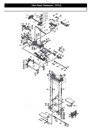
Fitting the side guard<br />
Slide the two sections of the Side Guard (K)<br />
together until they fit between the pivot<br />
brackets on the slide chassis. Loosely fit the<br />
short M5 x 8 screw (i) and a M5 Nyloc nut (h)<br />
to hold them together.<br />
Fit the two longer M5<br />
x 25 screws (j) and<br />
M5 Nyloc nuts through<br />
the pivot brackets and<br />
into the guard flanges.<br />
Tighten until the guard<br />
is firm, but still free to<br />
pivot. Finally, tighten<br />
the screw holding the two halves together.<br />
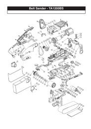
Fitting the trigger strap<br />
Before fitting the Trigger Strap (q) always<br />
ensure that the saw is disconnected<br />
from the power and that the switch on<br />
the <strong>Workcentre</strong> front panel is in the "OFF"<br />
position.<br />
Wrap the Trigger Strap (q) around the handgrip<br />
with the furry side facing outwards. Pass the<br />
strap through the buckle, until the security<br />
loop has passed<br />
through. If your saw<br />
has a safety lock-out<br />
button press it and then<br />
tighten the strap until<br />
the trigger clicks "ON".<br />
GB<br />
6 Fitting The <strong>Triton</strong> Saw<br />
Fitting The <strong>Triton</strong> Saw 7