Operating Manual Bedienungsanleitung Manual ... - CooperSurgical
Operating Manual Bedienungsanleitung Manual ... - CooperSurgical
Operating Manual Bedienungsanleitung Manual ... - CooperSurgical

You also want an ePaper? Increase the reach of your titles
YUMPU automatically turns print PDFs into web optimized ePapers that Google loves.
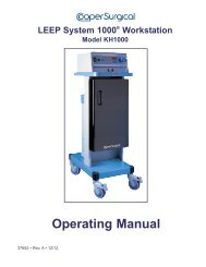
<strong>Operating</strong> <strong>Manual</strong><br />
<strong>Bedienungsanleitung</strong><br />
<strong>Manual</strong> de funcionamiento<br />
Manuel d’utilisation<br />
<strong>Manual</strong>e di funzionamento<br />
34371 • Rev. C • 3/11 0086
English ................................................................................................................................ Page 1<br />
Deutsch / German ............................................................................................................ Seite 21<br />
Español / Spanish ........................................................................................................ Página 42<br />
Français / French ............................................................................................................. Page 63<br />
Italiano / Italian .............................................................................................................. Pagina 84<br />
LEEP System 1000 ®
LEEP System 1000 ®<br />
Table of Contents<br />
Section Content Page<br />
1. Professional Use Guide . . . . . . . . . . . . . . . . . . . . . . . . . . . . . . . . . . . . . . . . . . . . . . . . . . . 2<br />
2. System Features . . . . . . . . . . . . . . . . . . . . . . . . . . . . . . . . . . . . . . . . . . . . . . . . . . . . . . . . 7<br />
3. Specifications . . . . . . . . . . . . . . . . . . . . . . . . . . . . . . . . . . . . . . . . . . . . . . . . . . . . . . . . . . . 9<br />
4. Electrosurgical Precautions . . . . . . . . . . . . . . . . . . . . . . . . . . . . . . . . . . . . . . . . . . . . . . . 11<br />
5. Placement of the Patient Plate or Dispersive Electrode. . . . . . . . . . . . . . . . . . . . . . . . . 13<br />
6. Foot Pedal Switch . . . . . . . . . . . . . . . . . . . . . . . . . . . . . . . . . . . . . . . . . . . . . . . . . . . . . . 13<br />
7. Power Connection, Electrode Connection and Applying Power to Unit . . . . . . . . . . . . 13<br />
8. Operation . . . . . . . . . . . . . . . . . . . . . . . . . . . . . . . . . . . . . . . . . . . . . . . . . . . . . . . . . . . . . 13<br />
9. Safety Circuits . . . . . . . . . . . . . . . . . . . . . . . . . . . . . . . . . . . . . . . . . . . . . . . . . . . . . . . . . 14<br />
10. Practical Suggestions. . . . . . . . . . . . . . . . . . . . . . . . . . . . . . . . . . . . . . . . . . . . . . . . . . . . 14<br />
11. Cleaning . . . . . . . . . . . . . . . . . . . . . . . . . . . . . . . . . . . . . . . . . . . . . . . . . . . . . . . . . . . . . . 14<br />
12. Periodic Safety Checks . . . . . . . . . . . . . . . . . . . . . . . . . . . . . . . . . . . . . . . . . . . . . . . . . . 14<br />
13. Troubleshooting . . . . . . . . . . . . . . . . . . . . . . . . . . . . . . . . . . . . . . . . . . . . . . . . . . . . . . . . 15<br />
14. Liability Statement . . . . . . . . . . . . . . . . . . . . . . . . . . . . . . . . . . . . . . . . . . . . . . . . . . . . . . 16<br />
15. Warranty . . . . . . . . . . . . . . . . . . . . . . . . . . . . . . . . . . . . . . . . . . . . . . . . . . . . . . . . . . . . . . 16<br />
16. Service and Repair. . . . . . . . . . . . . . . . . . . . . . . . . . . . . . . . . . . . . . . . . . . . . . . . . . . . . . 16<br />
17. LEEP System 1000 ® EMC Compliance Information. . . . . . . . . . . . . . . . . . . . . . . . . . . . 17<br />
18. Explanation of Symbols . . . . . . . . . . . . . . . . . . . . . . . . . . . . . . . . . . . . . . . . . . . . . . . . . . 20<br />
Manufactured by:<br />
<strong>CooperSurgical</strong>, Inc.<br />
95 Corporate Drive<br />
Trumbull, CT 06611 USA<br />
<strong>CooperSurgical</strong> Customer Service:<br />
Phone: 203-601-5200<br />
Phone: 800-243-2974<br />
Fax: 800-262-0105<br />
Distributed by:<br />
LEEP System 1000 ®<br />
• <strong>Operating</strong> <strong>Manual</strong> • English<br />
1
Section 1<br />
Professional Use Guide<br />
IMPORTANT<br />
The user of this equipment, LEEP System 1000 ® , should be thoroughly trained in the techniques of<br />
Loop Electrosurgical Excision Procedures. This equipment has been designed for use with LEEP<br />
Electrosurgical Accessories. DO NOT use this equipment for any purpose other than that for which it<br />
has been designed.<br />
This manual contains information about the proper procedures for inspecting and preparing the<br />
equipment before its use, and its care and storage after use.<br />
This manual does not describe how an actual procedure is to be performed, nor is it meant to teach a<br />
beginner the proper technique or any of the medical considerations regarding the use of this equipment.<br />
<strong>CooperSurgical</strong> recommends that prospective user obtain appropriate training before using this<br />
equipment as improper use could be potentially hazardous to the patient and the user.<br />
This device SHOULD NOT be used without proper training.<br />
Training in the use of electrosurgical equipment should include:<br />
1. A review of the published literature regarding the procedure of interest.<br />
2. A review of the Loop Electrosurgical Excision Procedure (LEEP) Syllabus available from<br />
<strong>CooperSurgical</strong>.<br />
3. Attendance at a course or courses offered by physicians experienced with the Loop<br />
Electrosurgical Excision Procedure.<br />
4. Hands-on preceptor training from an experienced practitioner.<br />
Please read this entire manual carefully to become familiar with each of the controls and features before<br />
making any attempt to use the equipment clinically.<br />
Instructions contained in the operating manuals of any equipment to be used in conjunction with this<br />
equipment must be followed to avoid any possible hazard from incompatibility.<br />
Failure to thoroughly understand and follow the instructions given in this manual may result in serious<br />
injury to the patient and/or the operator. Failure to follow the instructions given in this manual may result<br />
in damage to or malfunction of this equipment.<br />
No long-term follow-up studies with this device have been performed as to recurrence rates. The effects<br />
of Loop Electrosurgical Excision Procedure on pregnancy outcome are not known.<br />
SAFETY PRECAUTIONS MUST ALWAYS BE EXERCISED WHEN USING ELECTRICAL EQUIPMENT<br />
TO PREVENT OPERATOR/PATIENT SHOCK, FIRE HAZARD AND EQUIPMENT DAMAGE.<br />
CAUTION: U.S. Federal law restricts this device to sale by or on the order of a physician. This device<br />
SHOULD NOT be used without proper training and preceptorship.<br />
If any questions arise regarding the information contained in this manual, the operation or safety of the<br />
equipment or service, please contact your local distributor.<br />
1.1 Indications<br />
The LEEP procedure is indicated in the diagnosis and treatment of some Cervical Intraepithelial<br />
Neoplasia (CIN) in patients where there is:<br />
• Cytological or colposcopic suspicion of CIN 2 or worse (including micro-invasion)<br />
• Persistent CIN 1 (of more than 12 months duration)<br />
• CIN 1 where the likelihood of follow-up is low or when the patient requests treatment<br />
• A suspicion (cytological or colposcopic) of a glandular intraepithelial abnormality<br />
2 LEEP System 1000 ® • <strong>Operating</strong> <strong>Manual</strong> • English (Continued)
• A disparity between the cytological and colposcopic diagnoses<br />
• External anogenital lesion<br />
• Large vaginal intraepithelial neoplastic (VAIN) lesions<br />
• Cervical conization indications<br />
1.2 Contraindications<br />
The following are typical contraindications for performing the LEEP procedure. It is imperative<br />
that the physician carefully weigh the risks and benefits of treatment versus non-treatment in<br />
contraindicated patients:<br />
• Pregnancy<br />
• Gross invasive carcinoma of the cervix<br />
• A bleeding disorder<br />
• Acute or active inflammation of the cervix, endometrium, fallopian tube, ovary or peritoneum<br />
(cervicitis, endometritis, tubo-ovarian inflammatory disease or pelvic inflammatory disease)<br />
• “Positive” endocervical curettage or a lesion in which the endocervical limit cannot be<br />
visualized colposcopically<br />
• Less than 3 months postpartum<br />
• Equivocal cervical abnormality<br />
1.3 LEEP Procedure and Technique<br />
It is recommended that the patient be provided with a brief description of the procedure and the<br />
equipment that will be used (ACOG, <strong>CooperSurgical</strong>, and other professional organizations and<br />
equipment manufacturers have produced patient information brochures on the LEEP procedure that<br />
address many of the questions and concerns that your patients may have regarding the procedure).<br />
1.4 Safety Precautions<br />
1. This equipment should only be used by a thoroughly trained physician in an adequately<br />
equipped medical facility.<br />
2. Replacement accessories and patient return pads should be kept on hand since defective active<br />
accessory or patient return pads can result in sub-standard performance of this equipment.<br />
3. This equipment should only be connected to a properly grounded receptacle. NEVER use an<br />
adapter that defeats the ground of the built-in three (3) prong plug.<br />
4. Care must be exercised when handling liquids around electrical equipment. DO NOT attempt to<br />
operate this equipment if liquids have spilled on the unit. DO NOT use flammable liquids around<br />
electrical equipment.<br />
5. This equipment should never be used in conjunction with other equipment for which safety<br />
against leakage current has not been established.<br />
6. When this equipment is operated:<br />
a. A Patient Return Pad (dispersive pad) of adequate surface area MUST be properly<br />
attached to the patient or the risk of accidental burns will exist.<br />
b. The Patient Return Pad (dispersive pad) should be placed as close as possible to the<br />
site of use of the active accessory but MUST NEVER be placed so as to allow the<br />
patient’s heart to be in the pathway from the active accessory to the return electrode!<br />
7. The user should thoroughly understand the principles and use of radio frequency (RF) current<br />
before using this equipment. This understanding is essential to avoid the hazard of shocks or<br />
burns to the user and/or the patient.<br />
LEEP System 1000 ®<br />
• <strong>Operating</strong> <strong>Manual</strong> • English (Continued)<br />
3
PROPER<br />
Generator<br />
RF current through<br />
patient to return pad<br />
Active Electrode<br />
Patient<br />
Grounded<br />
Metal Case<br />
Two conductor<br />
patient electrode<br />
continuity monitor<br />
Patient return pad<br />
(Thigh)<br />
Patient may be<br />
grounded<br />
IMPROPER<br />
Generator<br />
Burn occurs at small<br />
grounded contact<br />
RF<br />
EKG<br />
Isolated<br />
ESU<br />
Surgeon touches electrode<br />
to grounded object<br />
RF current flows from ground<br />
through EKG pad, through<br />
patient to return pad<br />
IMPROPER<br />
Generator<br />
RF current flows<br />
from electrode<br />
Burn occurs at small<br />
grounded contact<br />
RF<br />
EKG<br />
Isolated or<br />
grounded ESU<br />
Patient return pad touches<br />
grounded table<br />
RF current returns to patient<br />
return pad via ground path<br />
4 LEEP System 1000 ® • <strong>Operating</strong> <strong>Manual</strong> • English (Continued)
8. The instructions for use described in this manual must be followed; otherwise, compromised<br />
safety, malfunction, injury to the operator and/or patient, or costly damage to the unit may occur.<br />
9. There are no user-serviceable parts within the housing. Repairs to this equipment should only<br />
be performed by authorized <strong>CooperSurgical</strong> service personnel. For service information, please<br />
contact your local distributor (see page 1).<br />
1.5 Electrosurgical Procedures<br />
This section provides only general information about the use of electrosurgical devices. Only the user<br />
can evaluate the clinical factors involved with each patient and determine if the use of this equipment is<br />
indicated. The user must then decide on the specific technique and procedure that will accomplish the<br />
desired clinical effect.<br />
WARNING<br />
Electrosurgical generators are designed to allow the controlled destruction of tissue and<br />
are inherently dangerous if operated improperly.<br />
REPORTED PROBLEMS DUE TO IMPROPER OPERATION DURING ELECTROSURGICAL<br />
PROCEDURES HAVE INCLUDED:<br />
• Inadvertent activation with resultant tissue damage at the wrong site and/or<br />
equipment damage.<br />
• Alternate current pathways resulting in burns where the patient or physician or<br />
assistant is in contact with exposed metal.<br />
• Explosions caused by electrosurgical sparking in a flammable gas mixture (i.e.,<br />
explosive anesthetic gases and the inappropriate use of alcohol and other<br />
flammable liquids).<br />
• Perforation and massive hemorrhage.<br />
• A proper patient return pad pathway is extremely important during any monopolar<br />
electrosurgical procedure. Every effort must be made to ensure that throughout<br />
the electrosurgical procedure, an adequate surface area is provided and remains in<br />
proper contact with the patient to reduce the current density below a level that might<br />
cause inadvertent tissue damage where the patient return pad has been applied.<br />
1.5.1 Setting the Controls<br />
1.5.1.1 Electrosurgical Tissue Effect<br />
Delivery of continuous sinusoid waveform currents through a small electrode at appropriate<br />
power levels can cause rapid heating of the intracellular fluids in the cells in close proximity<br />
to the electrode, turning these fluids to steam. The significant increase in volume<br />
(approximately 5 times) causes cellular structure to rupture, creating the clinical effect of<br />
“CUT”, with little or no hemostatic effect along the margin of the divided tissue. Delivery of<br />
short duration pulses of RF currents through a small electrode at appropriate power levels<br />
can cause heating of intracellular fluids at a more gradual pace. This allows evaporation of<br />
these fluids without rupturing the cellular structure, creating the clinical effect of desiccation,<br />
or “COAG”, without the division of tissue. By varying the pulse to an intermediate duration,<br />
it is possible to get a clinical effect that combines, or “blends”, the clinical characteristics of<br />
CUT and COAG yielding the effect referred to as “BLEND”, where tissue is divided with a<br />
desirable amount of hemostatis along the margins of the divided tissue.<br />
The electrosurgical effect may vary throughout the procedure, requiring the operator to<br />
adjust the relative power setting of the generator.<br />
LEEP System 1000 ®<br />
• <strong>Operating</strong> <strong>Manual</strong> • English (Continued)<br />
5
1.5.1.2 Select the output mode (i.e., “CUT”, “BLEND”, or “COAG”) by pushing the<br />
corresponding buttons.<br />
Output Mode Waveform Description General Effect<br />
CUT Continuous 450 kHz sinusoid Cutting without Hemostatis<br />
with minimal modulation<br />
BLEND Interrupted 450 kHz sinusoid Cutting with minimal<br />
intermediate duty cycle<br />
Hemostatis<br />
COAG Bursts of 450 kHz sinusoid Coagulation without Cutting<br />
short duty cycle<br />
1.5.1.3 Set the level of output power (confirmed on the digital display) by using the output<br />
power selector buttons as desired.<br />
WARNING<br />
The degree and speed of electrosurgical effect is largely dependent on Current Density<br />
at the point of contact of the active electrode. Loop electrosurgical excision procedure<br />
electrodes from other manufacturers may vary in the diameter thickness, size and<br />
configuration of the cutting wire. This may result in SIGNIFICANT changes in the<br />
electrosurgical effect at a given output power level setting. The use of <strong>CooperSurgical</strong><br />
LEEP Electrodes is recommended.<br />
1.5.1.4 If the use of other output modes is anticipated, repeat steps #1 and #2 as desired.<br />
The output power level settings selected for each output mode will be retained as<br />
long as the unit remains ON.<br />
1.5.2 Guidelines for Power Settings<br />
The following guidelines for power settings may vary due to the technique, clinical circumstances,<br />
accessory style, cutting wire diameter, size, configuration and user preference.<br />
Recommended Power Settings (Watts) for the <strong>CooperSurgical</strong> LEEP System 1000 Electrodes<br />
Style<br />
Loop Width (cm)<br />
Ball<br />
Needle<br />
Electrodes<br />
Electrodes<br />
1.0 1.5 2.0 Macro Micro<br />
CUT* — — — — — 14–24<br />
BLEND 22–36 30–40 34–36 — — —<br />
COAG — — — 40–56 + 30–36 —<br />
NOTE<br />
* If the cut mode is desired,<br />
use the recommended<br />
settings for the blend mode.<br />
+ The power setting can be<br />
increased beyond 56 to<br />
coagulate any bleeding<br />
points as required.<br />
The above settings are for reference only and can be varied based on specific situations and the<br />
experience of the operator.<br />
REMEMBER, THIS IS NOT AN ATTEMPT TO TEACH ELECTROSURGICAL TECHNIQUE.<br />
The practitioner who lacks experience should not attempt the procedures described below based<br />
solely on this information; instead, the skills required should be acquired in the time-honored preceptor<br />
manner. Call your local distributor (see page 1) for information on courses that offer instruction on the<br />
proper use of electrosurgical generators and accessories.<br />
NOTE: The best initial effect is accomplished with the cutting wire in only light contact with tissue. Tight<br />
pressure may cause desiccation of the tissue and will delay the start of the cutting effect.<br />
6 LEEP System 1000 ® • <strong>Operating</strong> <strong>Manual</strong> • English (Continued)
IMPORTANT<br />
The initial use of any electrosurgical generator always involves some degree of “trial and<br />
error”. This is true even when only changing from numbered dials to digital display models<br />
within the same manufacturer’s product line. As with any other therapeutic device, it is<br />
very helpful to experiment IN VITRO or on animal sample tissue before using any<br />
electrosurgical generator or methods which are not familiar.<br />
The microprocessor control system of this unit was developed specifically to provide the<br />
best possible performance for loop electrosurgical excision procedures. By exhibiting<br />
patience and following the guidelines offered, the practitioner should easily become<br />
familiar with the performance characteristics of the LEEP System 1000.<br />
1.5.3 Thermal Effects on Tissue Treated with Loop Electrodes<br />
Thermal effects on tissue specimens may include (1) thermal coagulation injury of the cervix, up to<br />
one-third the thickness of normal epithelium of the cervix, (2) fragmentation of squamous epithelium of<br />
the cervix attributable to long exposure periods along the excision site that allows heat to dissipate<br />
laterally, and (3) partial coagulation of the endocervical epithelium because of lateral radiation of heat.<br />
Therefore, the loop electrosurgical excision procedure (LEEP) may produce thermal effects at the<br />
periphery of the excised tissue and may make histopathologic interpretation difficult or impossible<br />
and not allow accurate diagnosis and need for further treatment.<br />
Section 2<br />
System Features<br />
• Microprocessor controlled for increased precision, accuracy, repeatability, and safety.<br />
• Adequate power for all LEEP monopolar electrosurgical procedures.<br />
• Accurate selection of discrete power levels.<br />
• Digital display of output power levels.<br />
• Choice of radio frequency wave forms including CUT, BLEND, and COAG to accommodate<br />
subtle differences in technique and accessory performance.<br />
• Patient plate continuity monitoring with audible alarm.<br />
• Distinct audible tones for CUT/BLEND modes and COAG mode with associated MODE light.<br />
• Fully regulated isolated output power.<br />
• Meets or exceeds IEC 601-2-2, second edition.<br />
• Non-electric pneumatic foot pedal to maximize safety.<br />
• Choice of reusable or disposable patient plate.<br />
• Choice of reusable or disposable handpiece.<br />
• Choice of reusable or disposable electrodes.<br />
• Output power safety audible alarm with automatic power shut off.<br />
• Class 1, type BF, protected for use with defibrillator.<br />
• Membrane switching to maximize cleanliness and ease of use.<br />
LEEP System 1000 ®<br />
• <strong>Operating</strong> <strong>Manual</strong> • English (Continued)<br />
7
5<br />
6<br />
7<br />
10<br />
1 2 8 9 3 4<br />
CONTROLS<br />
1. Main switch<br />
2. Socket for pedal switch<br />
3. Socket for active electrodes<br />
4. Socket for neutral electrode<br />
5. Warning light of neutral electrode<br />
alarm (red)<br />
6. Coagulation light (blue)<br />
7. Pure cut and blend light (yellow)<br />
8. Mode control:<br />
9. Power control<br />
10. Display<br />
Pure Cut<br />
Blend Cut<br />
Coag<br />
Classification I Type BF protected against defibrillator effects<br />
Floating output circuit<br />
10 °C<br />
45 °C<br />
Cautions, consult this manual for safety precautions<br />
Pedal connection<br />
Active handle connection<br />
Patient plate connection<br />
High voltage<br />
Temperature limitation<br />
8 LEEP System 1000 ® • <strong>Operating</strong> <strong>Manual</strong> • English (Continued)
Section 3<br />
Specifications<br />
Meets or exceeds IEC 60601-1, IEC 60601-1-2 and IEC 60601-2-2 specifications.<br />
Product conforms to the Medical Device Directive 93/42/EEC.<br />
ELECTRICAL<br />
INPUT VOLTAGE: 95 - 135 VAC 50/60 Hz 190 - 250 VAC 50 Hz<br />
CURRENT: 2.3 amps max. 2.3 amps max.<br />
LOW FREQUENCY LEAKAGE: Less than 50 micro-amps Less than 50 micro-amps<br />
FUSES: 2.5 amps, 250V, T type 1.6 amps, 250V, T type<br />
POWER CORD:<br />
American Cord Set, Hospital Grade,<br />
NEMA 5-15P/IEC 320 female, 250 cm long<br />
ENVIRONMENTAL CONDITIONS (Usage Shipping and Storage)<br />
Environmental Temperature: Between 10 °C and 45 °C (50 °F and 113 °F)<br />
Relative Humidity: Between 30% and 75%<br />
PHYSICAL<br />
Dimensions:<br />
Weight:<br />
305 mm x 267 mm x 115 mm (12 in. x 15.5 in. x 4.5 in.)<br />
7.250 Kg (16 pounds)<br />
ELECTROSURGICAL OUTPUT<br />
RF Output Frequency: 450 kHz<br />
RF OUTPUT POWER: Volts p-p Max Duty Crest<br />
(open circuit) Cycle Factor<br />
CUT 0-100 watts RMS* 830 --- 1.4<br />
BLEND 0-100 watts RMS* 1200 60% 2.0<br />
COAG 0-80 watts RMS* 3800 10% 5.5<br />
NOTE: *Stable to >800 ohms (calibration at 500 ohms)<br />
RF ISOLATION: Less than 150 milli-amps at 200 ohms<br />
CLASSIFICATION . . . . . . . . . I-Type BF<br />
OUTPUT CIRCUIT . . . . . . . . Floating output. Protected against the effects of the defibrillator.<br />
WORKING MODE . . . . . . . . . Discontinuous maximum duty cycle: 10/30 sec.<br />
COOLING . . . . . . . . . . . . . . . Convection cooling without fan<br />
CONTROL . . . . . . . . . . . . . . Foot pedal operated (pneumatic) with audible signals and mode lights<br />
AUDIBLE SIGNALS AND LIGHTS FOR OPERATION AND ALARM:<br />
MAIN . . . . . . . . . . . . . . . . . . . . . . . . . . . . . Green light<br />
ALARM, PATIENT PLATE CONTINUITY . . Low pitch intermittent audible alarm - red light<br />
ALARM, OUTPUT POWER . . . . . . . . . . . . Higher pitch intermittent audible alarm<br />
CUT AND BLEND MODES . . . . . . . . . . . . Low pitch audible signal - yellow light<br />
COAGULATION MODE . . . . . . . . . . . . . . . High pitch audible signal - blue light<br />
NOTE: Specifications subject to change.<br />
LEEP System 1000 ®<br />
• <strong>Operating</strong> <strong>Manual</strong> • English (Continued)<br />
9
OUTPUT POWER AT 500 OHMS<br />
PURE CUT . . . . . . . . . .100 W RMS (open circuit 830 Vp-p; crest factor 1.43)<br />
Waveform: sinusoidal at 450 kHz<br />
BLEND CUT . . . . . . . . .100 W RMS (open circuit 1200 Vp-p; crest factor 2)<br />
Waveform: sinusoidal at 450 kHz<br />
Duty cycle: 60%<br />
COAGULATION . . . . . .80 W RMS (open circuit 3800 Vp-p; crest factor 5.5)<br />
Waveform: sinusoidal at 450 kHz<br />
Duty cycle: 10%<br />
Output Power Diagrams according to PAR.6.8.3 (IEC 601-2-2)<br />
Tolerance: 20% according to PAR.50.2 (IEC 601-2-2)<br />
Power (500 ohm)<br />
(W)<br />
100<br />
75<br />
50<br />
25<br />
PURE CUT<br />
BLEND CUT<br />
25 50 75 100<br />
Setting<br />
Power (500 ohm)<br />
(W)<br />
80<br />
60<br />
40<br />
20<br />
COAGULATION<br />
20 40 60 80<br />
Setting<br />
10 LEEP System 1000 ® • <strong>Operating</strong> <strong>Manual</strong> • English (Continued)
Power<br />
1 PURE CUT - POWER 100%<br />
2 PURE CUT - POWER 50%<br />
Impedance<br />
(ohm)<br />
Power<br />
1 BLEND CUT - POWER 100%<br />
2 BLEND CUT - POWER 50%<br />
Impedance<br />
(ohm)<br />
Power<br />
1 COAGULATION - POWER 100%<br />
2 COAGULATION - POWER 50%<br />
Impedance<br />
(ohm)<br />
Section 4<br />
Electrosurgical Precautions<br />
The safety and effectiveness of electrosurgery is dependent, to a large degree, upon the skill of the<br />
user/operator. It is important that the user/operator read, understand, and follow the operating<br />
instructions supplied with the <strong>CooperSurgical</strong> LEEP System and thoroughly understand the principles<br />
and use of radio frequency (RF) electrosurgical systems.<br />
WARNING: Electrosurgery uses radio-frequency energy to cut and coagulate tissue. Due to the<br />
sparking and heat associated with electrosurgery do not use with flammable anesthetics, or other<br />
flammable gases, near flammable fluids or objects or with oxidizing agents.<br />
• DO NOT use electrosurgery in the presence of flammable gases, flammable liquids, or<br />
flammable objects in oxygen enriched atmospheres, nitrous oxide (N 2 O) atmosphere or in<br />
the presence of other oxidizing agents.<br />
• Prevent accumulation of oxygen, nitrous oxide (N 2 O), and flammable gases, under surgical<br />
drapes, or within the area where electrosurgery is performed, and it should be avoided in case<br />
of thorax or head operations unless safely aspirated.<br />
• Verify that all oxygen connections are leak-free before and during the use of electrosurgery.<br />
• DO NOT use electrosurgery in the presence of naturally occurring flammable gases which may<br />
accumulate in body cavities such as the bowel.<br />
LEEP System 1000 ®<br />
• <strong>Operating</strong> <strong>Manual</strong> • English (Continued)<br />
11
• DO NOT use electrosurgery in the presence of flammable liquids, such as skin prepping<br />
agents. Avoid pooling of flammable liquids near the electrosurgery site or in human body<br />
cavities such as the umbilicus or vagina.<br />
• DO NOT place the electrosurgery active electrode near or in contact with flammable materials,<br />
such as cotton, wool or gauze. The active electrode is hot from use and can cause fire.<br />
• It is possible that the radio frequency can interfere with the electronic circuitry in the pacemaker.<br />
To reduce the risk locate the patient return electrode as close as possible to the treatment site<br />
and ensure that the current path between the surgical site and the patient return electrode is as<br />
far removed from the heart as possible. For the gynecology procedures locate the patient return<br />
electrode on the patient's upper thigh or under buttocks. Always monitor pacemaker patients<br />
during surgery. In case of doubt ask the pacemaker manufacturer and/or cardiology<br />
department.<br />
• In case of loss of power, turn the system off.<br />
• The possibility exists that the radio frequency can interfere with other medical equipment when<br />
the electrosurgical system is operating. To reduce the interference, physically separate the<br />
device, utilize different electrical outlets that are hospital grounded, do not allow cables to come<br />
in contact with each other, and utilize shielded devices where possible.<br />
• The fixed output power level should be adjusted to the lowest power setting that will<br />
successfully complete the procedure. Refer to the following recommended power settings for<br />
the <strong>CooperSurgical</strong> LEEP System 1000 Electrodes.<br />
Recommended Power Settings (Watts) for the <strong>CooperSurgical</strong> LEEP System 1000 Electrodes<br />
Needle<br />
Style Loop Width (cm) Ball<br />
Electrodes<br />
Electrodes<br />
1.0 1.5 2.0 Macro Micro<br />
CUT* — — — — — 14–24<br />
BLEND 22–36 30–40 34–36 — — —<br />
COAG — — — 40–56 + 30–36 —<br />
The above power settings are for reference only and can be varied based on specific situations and the<br />
experience of the operator.<br />
NOTE: * If the cut mode is desired, use the recommended settings for the blend mode.<br />
+ The power setting can be increased beyond 56 to coagulate any bleeding points<br />
as required.<br />
• Skin to skin contact, for instance between the patient's arm and body, should be avoided by the<br />
placement of an appropriate separating device such as two to three inches of dry gauze. This<br />
will reduce the potential for alternate site burns.<br />
• If monitoring, stimulation, imaging or similar devices are used simultaneously with electrosurgery<br />
the monitoring electrodes must be placed as far as possible from the electrosurgery site and the<br />
patient return electrode. Position the patient return electrode close to the electrosurgery site, for<br />
example, on the thigh when treating the cervix. NOTE: Monitoring needle electrodes are not<br />
recommended.<br />
• The electrical cord of the generator should be connected to a properly grounded receptacle.<br />
Extension cords and/or adapter plugs should not be used.<br />
• The connecting cables to the electrosurgery electrodes should be placed so that they do not<br />
come in contact with the patient, other cables, or cross each other.<br />
• Remove any metal items from the patient: for example, rings, chains, etc.<br />
• Use accessories supplied by <strong>CooperSurgical</strong>; they are specifically designed for the<br />
LEEP System 1000.<br />
• Do not use old or worn accessories.<br />
12 LEEP System 1000 ® • <strong>Operating</strong> <strong>Manual</strong> • English (Continued)
Section 5<br />
Placement of the Patient Plate or Dispersive<br />
Electrode<br />
When using an electrosurgical system, it is very important that all the current delivered to the patient<br />
returns correctly to the unit via the dispersive patient plate only.<br />
Section 6<br />
• The patient must be positioned correctly on the operating table. The patient and operator must<br />
not come in contact with any metal conductive surfaces.<br />
• The patient plate must securely contact a vascular area close to the operating site. For a<br />
gynecology procedure the preferred sites are the patient's thigh (disposable adhesive pads) or<br />
under the patient's buttocks (reusable metal plate). The contact area must be clean, free of<br />
body lotions, shaved, and massaged for good circulation. The contact area of the patient plate<br />
must be maximized and frequently checked for uniform contact during the procedure, especially<br />
if the patient has moved or if liquids have contacted the patient plate. A CONDUCTIVE GEL IS<br />
RECOMMENDED. The patient plate MUST NEVER be placed so as to allow the patient's heart<br />
to be in the pathway from the active electrode.<br />
• Power delivery to the operative site may be decreased appreciably if alternate pathways exist;<br />
for example, through the metal operating table, crossed handpiece/patient plate cables, etc.<br />
Foot Pedal Switch<br />
Connect the foot pedal switch to the socket (2) without activating the pedal, and tighten the threaded<br />
plug. This is an air (pneumatic) operated control. There is no electric current, offering maximum safety.<br />
Section 7<br />
Power Connection, Electrode Connection and<br />
Applying Power to Unit<br />
(Refer to the diagram on page 8)<br />
A. Check that power input corresponds to the technical data on the back of the unit. Plug the<br />
detachable cord into the back of the unit. Plug the power cord into the appropriate grounded wall<br />
outlet, ensuring that the ESU on/off switch is in the “OFF” position.<br />
B. Connect dispersive patient plate to the socket (4).<br />
C. Connect the active electrode handpiece to the socket (3) and tighten electrode of choice in<br />
the handpiece.<br />
D. Turn ON the unit by the power switch (1). The unit automatically performs a SELF TEST that<br />
checks RAM memory, EPROM memory, supply voltage, signal modulation and the following<br />
displays; function selector green lights, digital display, cut and coagulant yellow light, coagulation<br />
blue light, and the audible signal. When the unit passes SELF TEST the display will show current<br />
software revision i.e., r2A, r2B for several seconds then goes blank.<br />
Section 8 Operation<br />
Setting Power (refer to diagram on page 8)<br />
A. Control (8) sets the cut mode power output. The unit automatically powers up to cut mode<br />
when turned ON. The top LED lights on the selector (8) and control (9) sets the power.<br />
B. Control (8) selects blend mode (center LED) and control (9) sets the power.<br />
C. Control (8) selects coagulation mode (bottom LED) and control (9) sets the power.<br />
Power settings are stored when the system is ON and will appear automatically on the display (10)<br />
according to the selection of power mode by the control (8) during the procedure.<br />
Power may be changed at any time during the operation, except when the unit is activated by the<br />
foot pedal.<br />
At the end of the procedure turn the system OFF, and safely store the equipment and accessories.<br />
Power will reset to zero.<br />
LEEP System 1000 ®<br />
• <strong>Operating</strong> <strong>Manual</strong> • English (Continued)<br />
13
Section 9<br />
Safety Circuits<br />
The LEEP 1000 is equipped with two (2) safety circuits. The first one checks the dispersive patient plate<br />
connection. The second one turns off the power in case of an internal failure. When activating the unit<br />
by the foot pedal, a power delivery higher than the one selected will stop power delivery and at the<br />
same time give an audible signal similar to the patient plate alarm, but at a higher frequency.<br />
Section 10<br />
Practical Suggestions<br />
To optimize the performance when using an electrosurgical unit, the active electrode must be kept clean<br />
and use the lowest possible power setting required. Some sparks or superficial carbonization of the<br />
tissue may occur and the delivered power may decrease as a result of the electrical insulation caused<br />
by the tissue charring.<br />
Too high of a power setting results in a shorter surgical procedure, but may cause discharges and/or<br />
superficial carbonization, sparking, arcs, etc.<br />
Section 11<br />
Cleaning<br />
The unit may be cleaned with mild soap solution, but be sure that fluid does not enter the system.<br />
Wipe dry.<br />
Section 12<br />
Periodic Safety Checks<br />
The following safety checks should be performed at least every 24 months by a qualified person who<br />
has adequate training, knowledge, and practical experience to perform these tests.<br />
• Inspect the equipment and accessories for mechanical and functional damage.<br />
• Inspect the relevant safety labels for legibility.<br />
• Inspect the fuse to verify compliance with rated current and breaking characteristics.<br />
• Inspect acoustical and visual alarms/displays.<br />
• Verify that the device functions properly as described in the instructions for use.<br />
• Verify that the device shuts down the applied part circuit if the neutral electrode is disconnected.<br />
• Test the protection earth resistance according to IEC 601-1/1988: Limit 0.2 ohm.<br />
• Check that the output power is within tolerance versus the output control setting at a specified<br />
load resistance.<br />
• Check the power output at full and half setting of the output control over the range of load<br />
resistance as specified in the instructions for use (max. deviation is ± 20%).<br />
• Test the enclosure leakage current according to IEC 601-1/1988: Limit 100µA.<br />
• Test the leakage current according to IEC 601-1/1988: Limit 100µA (BF).<br />
• Test the patient leakage current under single fault condition with main voltage on the applied part<br />
according to IEC 601-1/1988: Limit: 5mA (BF).<br />
The leakage current should never exceed the limit. The data should be recorded in an equipment log. If<br />
the device is not functioning properly or fails any of the above tests, the device has to be repaired.<br />
14 LEEP System 1000 ® • <strong>Operating</strong> <strong>Manual</strong> • English (Continued)
Section 13<br />
Troubleshooting<br />
In the event of a failure during SELF TEST the display will show one of the error codes listed below:<br />
ALARM SIGNALS<br />
PROBLEM AUDIBLE TONE DISPLAY<br />
RAM Memory 1 kHz 100ms ON 250ms OFF “Er0”<br />
(during self-test phase)<br />
EPROM Memory 1 kHz 100ms ON 250ms OFF “Er1”<br />
(during self-test phase)<br />
Signal Modulation 1 kHz 200ms ON 250ms OFF “Er2”<br />
(during self-test phase)<br />
Signal Modulation 1 kHz 40ms ON 60ms OFF “Er2”<br />
(during activation phase)<br />
Supply Voltage 1 kHz 100ms ON 250ms OFF “Er3”<br />
(during self-test phase)<br />
Supply Voltage 1 kHz 40ms ON 60ms OFF “Er3”<br />
(during activation phase)<br />
Power Output 1 kHz 100ms ON 250ms OFF “Er5”<br />
(during activation phase)<br />
Foot Pedal Circuit 1 kHz 100ms ON 250ms OFF “Er6”<br />
(during self-test phase)<br />
Microcontroller Power Supply 1 kHz 100ms ON 250ms OFF “Er7”<br />
Dispersive Electrode 1 kHz 80ms ON 125ms OFF “nP”<br />
& Red Light<br />
A. If upon completion of Self Test the unit display reads Er0, Er1, Er2, Er3, Er5, Er6 or Er7 the unit<br />
must be returned to your local distributor for repair (see page 1).<br />
B. If upon completion of Self Test or if the unit stops functioning and the display reads nP and the<br />
red warning light is on, check the dispersive patient plate to insure that it is properly connected<br />
to the LEEP System 1000.<br />
C. If, following correct set-up of the system, it does not operate, works in an intermittent way, or<br />
stops working after a few seconds (without an audible signal), check for correct connection of<br />
pedal and its condition. The pedal is pneumatic, so even a slight leak can cause a performance<br />
problem.<br />
Proceed as follows:<br />
1. Tighten the threaded plug into the foot pedal socket.<br />
2. Then, push the pedal hard repeatedly to detect possible breaks in the tubing or in<br />
the pedal.<br />
D. If the unit, correctly connected, appears to deliver a lower power output than usual, check:<br />
1. The dispersive patient plate for complete contact (refer to dispersive plate sections).<br />
2. The condition of active electrodes (refer to “Section 10, Practical Suggestions”).<br />
3. The condition of the handpiece (cable continuity, contact of the electrode in the handpiece<br />
and the connector) by moving the cable and the connector and electrode to detect<br />
possible breaks and poor contact in the socket of the system.<br />
E. The LEEP System 1000 has a thermal protection circuit which will shut the unit off when internal<br />
operating temperatures exceed safe limits. Should the unit stop functioning with no alarm signal,<br />
assure that the system has adequate ventilation and that you have not exceeded the<br />
recommended duty cycle of 10/30 seconds. Should the thermal protection circuit be activated<br />
under normal operating conditions the system must be returned to your local distributor (see<br />
page 1) for servicing.<br />
LEEP System 1000 ®<br />
• <strong>Operating</strong> <strong>Manual</strong> • English (Continued)<br />
15
Section 14<br />
Liability Statement<br />
<strong>CooperSurgical</strong> guarantees the safety, reliability and performances of the LEEP System 1000 only if the<br />
installation, recalibrations and repairs are performed by personnel authorized by <strong>CooperSurgical</strong> and if<br />
the unit is used in compliance with given instructions in an area that meets all the applicable IEC<br />
requirements.<br />
Section 15<br />
Warranty<br />
<strong>CooperSurgical</strong>, Inc. warrants that the LEEP System 1000 (the “Product”) will be free from defects in<br />
materials and workmanship for a period of one (1) year from the original date of purchase.<br />
If the product should become inoperable due to a defect in material or workmanship during this one (1)<br />
year warranty period, <strong>CooperSurgical</strong> will, at its option, repair or replace the product. This limited<br />
warranty does not include replacement or service to repair damage resulting from improper installation,<br />
external electrical fault, accident, disaster, use for a purpose other than that for which originally designed<br />
or indicated in this manal, negligence, modification, service or repair by personnel not authorized by<br />
<strong>CooperSurgical</strong> or normal wear and tear and also does not apply to disposable or single or limited use<br />
items or components. The sole and exclusive remedy under this limited warranty shall be repair or<br />
replacement as provided herein.<br />
The foregoing limited warranty states the sole warranty made by <strong>CooperSurgical</strong> with respect to the<br />
product and all parts thereof, and is in lieu of any other warranty by <strong>CooperSurgical</strong> with respect to<br />
product. COOPERSURGICAL NEITHER MAKES NOR GRANTS ANY OTHER WARRANTY, EITHER<br />
EXPRESS OR IMPLIED, WITH RESPECT TO THE PRODUCT, INCLUDING WITHOUT LIMITATION,<br />
WARRANTIES OF MERCHANTABILITY OR FITNESS FOR A PARTICULAR PURPOSE. IN NO EVENT<br />
WILL COOPERSURGICAL BE LIABLE FOR ANY DAMAGES ARISING OUT OF THE LOSS OF USE<br />
OF THE PRODUCT, OR ANY OTHER INCIDENTAL OR CONSEQUENTIAL DAMAGES, WHETHER OR<br />
NOT COOPERSURGICAL HAS ADVANCE KNOWLEDGE OF THE POSSIBILITY OF SAME.<br />
No person, agent, distributor, dealer, or company is authorized to change or modify the terms of this<br />
limited warranty.<br />
Section 16<br />
Service and Repair<br />
No Customer Serviceable Parts<br />
Only <strong>CooperSurgical</strong> Inc. is authorized to service or repair this unit. If repair is attempted outside the<br />
factory, the warranty is considered void. <strong>CooperSurgical</strong> is not responsible for any injury resulting from<br />
repairs made by other individuals or organizations not certified by <strong>CooperSurgical</strong> Inc. If a repair is<br />
needed, equipment must be sanitized before it is returned to the factory and carefully packaged in a<br />
protective carton. All shipments must be pre-paid. COD packages will not be accepted. Return carton to:<br />
<strong>CooperSurgical</strong> Inc.<br />
Attention: Repair Department<br />
95 Corporate Drive • Trumbull, CT 06611 USA<br />
Phone: (203) 601-5200 • (800) 444-8456<br />
Fax: (203) 601-4743<br />
16 LEEP System 1000 ® • <strong>Operating</strong> <strong>Manual</strong> • English (Continued)
Section 17 LEEP System 1000 EMC Compliance<br />
Information<br />
Guidance and Manufacturer’s Declaration - Electromagnetic Immunity<br />
The LEEP System 1000 is intended for use in the electromagnetic environment specified below.<br />
The customer or the end user of the LEEP System 1000 should assure that it is used in such an<br />
environment.<br />
Immunity Test IEC 60601<br />
Test Level<br />
Compliance<br />
Level<br />
Electromagnetic Environmental -<br />
guidance<br />
Electromagnetic<br />
discharge (ESD)<br />
IEC 61000-4-2<br />
± 6 kV contact<br />
± 8 kV air<br />
± 6 kV contact<br />
± 8 kV air<br />
Floors should be wood, concrete or<br />
ceramic tile. If floors are covered with<br />
synthetic material, the relative humidity<br />
should be at least 30%.<br />
Electrical fast<br />
transient/burst<br />
IEC 61000-4-4<br />
± 2 kV for power<br />
supply lines<br />
± 1 kV for<br />
input/output lines<br />
± 2 kV for power<br />
supply lines<br />
± 1 kV for<br />
input/output lines<br />
Mains power quality should be that<br />
of a typical commercial or hospital<br />
environment.<br />
Surge<br />
IEC 61000-4-5<br />
± 1 kV differential<br />
mode<br />
± 2 kV common<br />
mode<br />
± 1 kV differential<br />
mode<br />
± 2 kV common<br />
mode<br />
Mains power quality should be that<br />
of a typical commercial or hospital<br />
environment.<br />
Voltage dips,<br />
short interruptions<br />
and voltage<br />
variations on<br />
power supply<br />
input lines<br />
IEC 61000-4-11<br />
95% dip in U T *)<br />
for 0.5 cycle<br />
40% U T *<br />
(60% dip in U T *)<br />
for 5 cycles<br />
70% U T *<br />
(30% dip in U T *)<br />
for 25 cycles<br />
95% dip in U T *)<br />
for 5 seconds<br />
95% dip in U T *)<br />
for 0.5 cycle<br />
40% U T *<br />
(60% dip in U T *)<br />
for 5 cycles<br />
70% U T *<br />
(30% dip in U T *)<br />
for 25 cycles<br />
95% dip in U T *)<br />
for 5 seconds<br />
Mains power quality should be that<br />
of a typical commercial or hospital<br />
environment. If the user of the LEEP<br />
System 1000 requires continued<br />
operation during power mains<br />
interruptions, it is recommended that<br />
the LEEP System 1000 be powered<br />
from an uninterruptible power supply<br />
or a battery.<br />
Power frequency<br />
(50/60 Hz)<br />
magnetic field<br />
IEC 61000-4-8<br />
3 A/m 3 A/m Power frequency magnetic fields<br />
should be at levels characteristic<br />
of a typical location in a typical<br />
commercial or hospital environment.<br />
NOTE: * U T is the AC mains voltage prior to application of the test level.<br />
LEEP System 1000 ®<br />
• <strong>Operating</strong> <strong>Manual</strong> • English (Continued)<br />
17
Immunity<br />
Test<br />
IEC 60601<br />
Test Level<br />
Compliance<br />
Level<br />
Electromagnetic Environmental – guidance<br />
Portable and mobile RF communications<br />
equipment should be used no closer to any part<br />
of the LEEP System 1000, including cables,<br />
than the recommended separation distance<br />
calculated from the equation applicable to the<br />
frequency of the transmitter.<br />
Recommended separation distance<br />
Conducted RF<br />
IEC 61000-4-6<br />
3 Vrms<br />
150 kHz to 80 MHz<br />
3 V<br />
Radiated RF<br />
IEC 61000-4-3<br />
3 V/m<br />
80 MHz to 2.5 GHz<br />
3 V/m<br />
80 MHz to 800 MHz<br />
800 MHz to 2.5 GHz<br />
where P is the maximum output power rating of<br />
the transmitter in watts (W) according to the<br />
transmitter manufacturer and d is the<br />
recommended separation distance in<br />
meters (m).<br />
Field strengths from fixed RF transmitters, as<br />
determined by an electromagnetic site survey a ,<br />
should be less than the compliance level in<br />
each frequency b .<br />
Interference may occur in the vicinity of<br />
equipment marked with the following symbol:<br />
NOTE 1<br />
NOTE 2<br />
At 80 MHz and 800 MHz, the higher frequency range applies.<br />
These guidelines may not apply in all situations. Electromagnetic propagation is affected by<br />
absorption and reflection from structures, objects and people.<br />
a<br />
b<br />
Field strengths from fixed transmitters, such as base stations for radio (cellular/cordless) telephones<br />
and land mobile radios, amateur radio, AM and FM radio broadcast and TV broadcast cannot be<br />
predicted theoretically with accuracy. To assess the electromagnetic environment due to fixed RF<br />
transmitters, an electromagnetic site survey should be considered. If the measured field strength in<br />
the location in which the LEEP System 1000 is used exceeds the applicable RF compliance level<br />
above, the LEEP System 1000 should be observed to verify normal operation. If abnormal<br />
performance is observed, additional measures may be necessary, such as reorienting or relocating<br />
the LEEP System 1000.<br />
Over the frequency range 150 kHz to 80 MHz, field strengths should be less than 3 V/m.<br />
18 LEEP System 1000 ® • <strong>Operating</strong> <strong>Manual</strong> • English (Continued)
Recommended separation distance between portable and mobile RF communications equipment<br />
and the Model LEEP System 1000.<br />
The LEEP System 1000 is intended for use in an electromagnetic environment in which radiated RF<br />
disturbances are controlled. The customer or the user of the LEEP System 1000 can help prevent<br />
electromagnetic interference by maintaining a minimum distance between portable and mobile RF<br />
communications equipment (transmitters) and the LEEP System 1000 as recommended below,<br />
according to the maximum output power of the communications equipment.<br />
Rated maximum<br />
output power of<br />
transmitter<br />
Watts<br />
Separation distance according<br />
to frequency of transmitter<br />
Meters<br />
150 kHz to 80 MHz 80 MHz to 800 MHz 800 MHz to 2.5 GHz<br />
0.01 0.1167 0.1167 0.2333<br />
0.1 0.3689 0.3689 0.7379<br />
1 1.1667 1.1667 2.3333<br />
10 3.6894 3.6894 7.3789<br />
100 11.667 11.667 23.333<br />
For transmitters rated at a maximum output power not listed above, the recommended separation<br />
distance d in meters (m) can be estimated using the equation applicable to the frequency of the<br />
transmitter, where P is the maximum output rating of the transmitter in watts (W) according to the<br />
transmitter manufacturer.<br />
For the LEEP System 1000<br />
V 1 = 3 Vrms<br />
E 1 = 3 V/m<br />
NOTE 1<br />
NOTE 2<br />
At 80 MHz and 800 MHz, the separation distance for the higher frequency range applies.<br />
These guidelines may not apply in all situations. Electromagnetic propagation is affected by<br />
absorption and reflection from structures, objects and people.<br />
LEEP System 1000 ®<br />
• <strong>Operating</strong> <strong>Manual</strong> • English (Continued)<br />
19
Section 18 Explanation of Symbols<br />
Reorder Number<br />
Serial Number<br />
!<br />
ATTENTION: See instructions for use.<br />
Fragile<br />
Keep Dry<br />
This side up<br />
CAUTION: U.S. Federal law restricts this device to sale by or on the order of a physician.<br />
0086<br />
Product conforms to the Medical Device Directive 93/42/EEC<br />
Authorized Representative in the European Community.<br />
LEEP System 1000 ® is a registered trademark of <strong>CooperSurgical</strong>, Inc.<br />
© 2011 <strong>CooperSurgical</strong>, Inc.<br />
95 Corporate Drive<br />
Trumbull, CT 06611 USA<br />
Phone: (800) 243-2974<br />
Fax: (800) 262-0105<br />
www.coopersurgical.com<br />
International<br />
Phone: (203) 601-9818<br />
Fax: (203) 601-4747<br />
EC REP<br />
Leisegang Feinmechanik GmbH<br />
Leibnizstraße 32<br />
D-10625, Berlin GERMANY<br />
34371 • Rev. C • 3/11<br />
20 LEEP System 1000 ® • <strong>Operating</strong> <strong>Manual</strong> • English (Continued)
<strong>Bedienungsanleitung</strong><br />
34371 • Rev. C • 3/11 0086
LEEP System 1000 ®<br />
Inhaltsverzeichnis<br />
Abschnitt Inhalt Seite<br />
1. <strong>Bedienungsanleitung</strong> . . . . . . . . . . . . . . . . . . . . . . . . . . . . . . . . . . . . . . . . . . . . . . . . . . . . . . . . . . . . 23<br />
2. Merkmale des Systems . . . . . . . . . . . . . . . . . . . . . . . . . . . . . . . . . . . . . . . . . . . . . . . . . . . . . . . . . . 28<br />
3. Technische Daten . . . . . . . . . . . . . . . . . . . . . . . . . . . . . . . . . . . . . . . . . . . . . . . . . . . . . . . . . . . . . . .30<br />
4. Vorsichtsmaßnahmen für die Elektrochirurgie . . . . . . . . . . . . . . . . . . . . . . . . . . . . . . . . . . . . . . . . . 32<br />
5. Anbringung der Patientenplatte oder der Neutralelektrode . . . . . . . . . . . . . . . . . . . . . . . . . . . . . . 34<br />
6. Fußpedalschalter . . . . . . . . . . . . . . . . . . . . . . . . . . . . . . . . . . . . . . . . . . . . . . . . . . . . . . . . . . . . . . . 34<br />
7. Netzanschluss, Elektrodenanschluss und Einschalten der Einheit . . . . . . . . . . . . . . . . . . . . . . . . 34<br />
8. Bedienung . . . . . . . . . . . . . . . . . . . . . . . . . . . . . . . . . . . . . . . . . . . . . . . . . . . . . . . . . . . . . . . . . . . . . 34<br />
9. Sicherheitsvorrichtungen . . . . . . . . . . . . . . . . . . . . . . . . . . . . . . . . . . . . . . . . . . . . . . . . . . . . . . . . . 35<br />
10. Praktische Vorschläge . . . . . . . . . . . . . . . . . . . . . . . . . . . . . . . . . . . . . . . . . . . . . . . . . . . . . . . . . . . 35<br />
11. Reinigung . . . . . . . . . . . . . . . . . . . . . . . . . . . . . . . . . . . . . . . . . . . . . . . . . . . . . . . . . . . . . . . . . . . . . 35<br />
12. Regelmäßige Sicherheitsüberprüfungen . . . . . . . . . . . . . . . . . . . . . . . . . . . . . . . . . . . . . . . . . . . . .35<br />
13. Problembehebung . . . . . . . . . . . . . . . . . . . . . . . . . . . . . . . . . . . . . . . . . . . . . . . . . . . . . . . . . . . . . . 36<br />
14. Haftungserklärung . . . . . . . . . . . . . . . . . . . . . . . . . . . . . . . . . . . . . . . . . . . . . . . . . . . . . . . . . . . . . . 37<br />
15. Garantie . . . . . . . . . . . . . . . . . . . . . . . . . . . . . . . . . . . . . . . . . . . . . . . . . . . . . . . . . . . . . . . . . . . . . . 37<br />
16. Wartung und Reparatur . . . . . . . . . . . . . . . . . . . . . . . . . . . . . . . . . . . . . . . . . . . . . . . . . . . . . . . . . . 37<br />
17. LEEP System 1000 ® EMV-Konformität . . . . . . . . . . . . . . . . . . . . . . . . . . . . . . . . . . . . . . . . . . . . . . 38<br />
18. Symbole . . . . . . . . . . . . . . . . . . . . . . . . . . . . . . . . . . . . . . . . . . . . . . . . . . . . . . . . . . . . . . . . . . . . . .41<br />
Hergestellt von:<br />
<strong>CooperSurgical</strong>, Inc.<br />
95 Corporate Drive<br />
Trumbull, CT 06611 USA<br />
Vertrieb durch:<br />
<strong>CooperSurgical</strong> Kundendienst:<br />
Tel: +1 203-601-5200<br />
Tel: +1 800-243-2974<br />
Fax: +1 800-262-0105<br />
22 LEEP System 1000 ® • <strong>Bedienungsanleitung</strong> • Deutsch / German
Abschnitt 1<br />
<strong>Bedienungsanleitung</strong><br />
WICHTIG<br />
Der Anwender dieses Geräts (LEEP System 1000 ® ) muss in dem Verfahren der elektrochirurgischen<br />
Schlingenexzision (Loop Electrosurgical Excision Procedures, LEEP) sorgfältig ausgebildet sein. Dieses Gerät ist<br />
zur Anwendung mit dem elektrochirurgischen LEEP-Zubehör vorgesehen. Dieses Gerät darf NUR für den<br />
vorgesehenen Zweck verwendet werden.<br />
Dieses Handbuch enthält Informationen über die richtigen Verfahren zur Überprüfung und Vorbereitung des Geräts<br />
vor der Anwendung sowie zur Pflege und Lagerung nach der Anwendung.<br />
In diesem Handbuch wird nicht die Durchführung eines tatsächlichen Verfahrens beschrieben. Auch ist es nicht als<br />
Handbuch zur Schulung der richtigen Technik für Anfänger oder der medizinischen Aspekte bei der Anwendung<br />
dieses Geräts vorgesehen. <strong>CooperSurgical</strong> empfiehlt, dass der prospektive Anwender vor der Anwendung dieses<br />
Geräts entsprechend geschult wird, weil eine unsachgemäße Anwendung eine potenzielle Gefahr für den Patienten<br />
und den Anwender darstellt.<br />
Dieses Gerät DARF NICHT ohne entsprechende Schulung angewendet werden.<br />
Die Schulung für die Anwendung von elektrochirurgischen Geräten muss Folgendes beinhalten:<br />
1. Durchsicht der veröffentlichten Literatur über das jeweilige Verfahren.<br />
2. Durchsicht der bei <strong>CooperSurgical</strong> erhältlichen Schulungsbroschüre über das Verfahren der<br />
elektrochirurgischen Schlingenexzision (Loop Electrosurgical Excision Procedure, LEEP).<br />
3. Teilnahme eines Fortbildungskurses über elektrochirurgische Schlingenexzision, der von Ärzten mit<br />
entprechender Ausbildung angeboten wird.<br />
4. Praktische Schulung durch einen erfahrenen Anwender.<br />
Lesen Sie das gesamte Handbuch vor der klinischen Anwendung des Geräts sorgfältig durch und machen Sie sich<br />
mit allen Bedienelementen und Merkmalen vertraut.<br />
Um mögliche Gefahren durch Inkompatibilität zu vermeiden, müssen die Anweisungen aller <strong>Bedienungsanleitung</strong>en<br />
der Geräte, die zusammen mit diesem Gerät verwendet werden, befolgt werden.<br />
Ein falsches Verständnis oder die Missachtung der Anweisungen in diesem Handbuch kann zu schweren<br />
Verletzungen des Patienten und/oder Bedieners führen. Bei Missachtung der Anweisungen dieses Handbuchs kann<br />
es zur Beschädigung oder Funktionsstörung dieses Geräts kommen.<br />
Es liegen keine Langzeitstudien über die Rezidivraten mit diesem Gerät vor. Die Wirkungen des Verfahrens der<br />
elektrochirurgischen Schlingenexzision auf den Schwangerschaftsverlauf sind unbekannt.<br />
BEI DER ANWENDUNG ELEKTROCHIRURGISCHER GERÄTE MÜSSEN IMMER DIE<br />
SICHERHEITSMASSNAHMEN BEFOLGT WERDEN, UM ELEKTROSCHOCKS BEIM PATIENTEN/BEDIENER,<br />
FEUERGEFAHR UND GERÄTESCHÄDEN ZU VERHINDERN.<br />
VORSICHT: Laut US-amerikanischem Bundesgesetz ist der Verkauf dieses Produkts nur an Ärzte oder im Auftrag<br />
von Ärzten erlaubt. Dieses Gerät DARF NICHT ohne entsprechende Schulung und entsprechende Praxisanleitung<br />
angewendet werden.<br />
Bei allen Fragen bezüglich der Informationen in diesem Handbuch, der Bedienung oder Sicherheit des Geräts oder<br />
der Serviceleistung wenden Sie sich an Ihren Händler vor Ort.<br />
1.1 Indikationen<br />
Das LEEP-Verfahren ist für die Diagnose und Behandlung bestimmter Arten der zervikalen intraepithelialen<br />
Neoplasie (CIN) bei Patientinnen vorgesehen, auf die Folgendes zutrifft:<br />
• Zytologischer oder kolposkopischer Verdacht auf CIN 2 oder schlechter (einschließlich Mikroinvasion)<br />
• Persistierende CIN 1 (Dauer mehr als 12 Monate)<br />
• CIN 1, wo die Wahrscheinlichkeit von Nachuntersuchungen gering ist oder wenn die Patientin eine<br />
Behandlung wünscht<br />
• Verdacht (zytologisch oder kolposkopisch) auf glanduläre intraepitheliale Läsionen<br />
LEEP System 1000 ®<br />
• <strong>Bedienungsanleitung</strong> • Deutsch / German (Fortsetzung)<br />
23
• Abweichung zwischen der zytologischen und kolposkopischen Diagnose<br />
• Externe anogenitale Läsion<br />
• Große vaginale, intraepitheliale neoplastische (VAIN) Läsionen<br />
• Indikationen für zervikale Konisation<br />
1.2 Kontraindikationen<br />
Die folgenden Kontraindikationen sind typisch für die Durchführung des LEEP-Verfahrens. Es ist entscheidend,<br />
dass der Arzt bei Patientinnen mit Kontraindikationen die Risiken und Vorteile der Behandlung gegen eine<br />
Nichtbehandlung abwägt:<br />
• Schwangerschaft<br />
• Großes invasives Zervixkarzinom<br />
• Blutungsstörung<br />
• Akute oder aktive Entzündung der Zervix, des Endometriums, Eileiters, Eierstocks oder Peritoneums<br />
(Zervizitis, Endometritis, Eileiter- und Eierstockentzündung oder entzündliche Beckenerkrankung)<br />
• „Positive“ endozervikale Kürettage oder Läsion, bei der der endozervikale Rand kolposkopisch nicht<br />
dargestellt werden kann.<br />
• Weniger als 3 Monate postpartum<br />
• Verdächtige, abnorme zervikale Veränderung<br />
1.3 LEEP-Verfahren und -Technik<br />
Der Patient sollte eine kurze, schriftliche Beschreibung des angewendeten Verfahrens sowie des angewendeten<br />
Geräts erhalten (ACOG, <strong>CooperSurgical</strong> und andere professionelle Organisationen und Gerätehersteller haben<br />
Patienteninformationsbroschüren über das LEEP-Verfahren erstellt, in denen viele der Fragen und Bedenken<br />
besprochen werden, die Ihre Patienten möglicherweise bezüglich des Verfahrens haben).<br />
1.4 Sicherheitsmaßnahmen<br />
1. Dieses Gerät darf nur von einem gründlich ausgebildeten Arzt in einer entsprechend eingerichteten<br />
medizinischen Einrichtung angewendet werden.<br />
2. Ersatzzubehör und Rückflusselektroden sollten jederzeit verfügbar sein, weil fehlerhaftes aktives Zubehör<br />
und fehlerhafte Rückflusselektroden zu einer minderwertigen Geräteleistungsfähigkeit führen können.<br />
3. Das Gerät darf nur an einen sachgerecht geerdeten Stecker angeschlossen werden. NIEMALS einen<br />
Adapter verwenden, der nicht vorschriftsmäßig geerdet ist.<br />
4. Beim Umgang mit Flüssigkeiten in der Nähe elektrischer Geräte Vorsicht walten lassen.<br />
Das Gerät NICHT bedienen, wenn Flüssigkeit auf der Einheit verschüttet wurde. KEINE entzündlichen<br />
Flüssigkeiten in die Nähe des elektrischen Geräts bringen.<br />
5. Dieses Gerät darf niemals in Verbindung mit Geräten verwendet werden, die keinen Schutz gegen<br />
Leckstrom aufweisen.<br />
6. Bei der Bedienung dieses Geräts muss Folgendes beachtet werden:<br />
a. Eine Rückflusselektrode (Neutralelektrode) mit ausreichend großer Fläche MUSS sorgfältig am<br />
Patienten angebracht werden, da sonst das Risiko von unbeabsichtigten Verbrennungen besteht.<br />
b. Die Rückflusselektrode (Neutralelektrode) muss so nah wie möglich am Anwendungsort des<br />
aktiven Zubehörs angebracht werden, DARF JEDOCH NIEMALS so angebracht werden, dass<br />
sich das Herz des Patienten im Stromkreis zwischen aktivem Zubehör und Rückflusselektrode<br />
befindet!<br />
7. Der Anwender muss vor der Nutzung dieses Geräts die Prinzipien und die Anwendung von<br />
Hochfrequenzgeräten (HF) gründlich verstanden haben. Nur dadurch kann einer Gefahr von elektrischen<br />
Schocks oder Verbrennungen beim Anwender und/oder Patienten vorgebeugt werden.<br />
24 LEEP System 1000 ® • <strong>Bedienungsanleitung</strong> • Deutsch / German (Fortsetzung)
RICHTIG<br />
Generator<br />
HF-Strom durch Patientin<br />
zur Rückflusselektrode<br />
Aktivelektrode<br />
Patientin<br />
Geerdetes<br />
Metallgehäuse<br />
Durchgangsüberwachung<br />
Zweileiterpatientenelektrode<br />
Rückflusselektrode<br />
(Oberschenkel)<br />
Patientin kann geerdet<br />
sein<br />
FALSCH<br />
Generator<br />
Verbrennung tritt bei<br />
geringem geerdeten<br />
Kontakt auf<br />
HF<br />
EKG<br />
Isolierte<br />
elektrochirurgische<br />
Einheit<br />
Chirurg berührt geerdetes<br />
Objekt mit Elektrode<br />
HF-Strom fließt von der Erde durch die<br />
EKG-Elektrode durch die Patientin zur<br />
Rückflusselektrode<br />
FALSCH<br />
Generator<br />
HF-Strom fließt von<br />
der Elektrode<br />
Verbrennung tritt bei geringem<br />
geerdeten Kontakt auf<br />
HF<br />
EKG<br />
Isolierte oder geerdete<br />
elektrochirurgische<br />
Einheit<br />
Rückflusselektrode berührt<br />
geerdeten Tisch<br />
HF-Strom kehrt über Erdpfad zur<br />
Rückflusselektrode zurück<br />
LEEP System 1000 ®<br />
• <strong>Bedienungsanleitung</strong> • Deutsch / German (Fortsetzung)<br />
25
8. Die Gebrauchsanweisungen in diesem Handbuch müssen befolgt werden, weil sonst die Sicherheit<br />
gefährdet oder Funktionsstörungen, Verletzungen des Bedieners und/oder Patienten oder kostspielige<br />
Beschädigungen der Einheit auftreten können.<br />
9. In dem Gehäuse befinden sich keine Teile, die vom Anwender gewartet werden können. Reparaturen am<br />
Gerät dürfen nur vom autorisierten Kundendienst von <strong>CooperSurgical</strong> durchgeführt werden. Wenn Sie<br />
Fragen zum Kundendienst haben, wenden Sie sich an Ihren Händler vor Ort (siehe Seite 22).<br />
1.5 Elektrochirurgische Verfahren<br />
Dieser Abschnitt enthält allgemeine Informationen über die Anwendung von elektrochirurgischen Geräten. Nur der<br />
Anwender kann die bei jedem Patienten vorliegenden klinischen Faktoren beurteilen und bestimmen, ob die<br />
Anwendung dieses Geräts indiziert ist. Der Anwender muss dann über die spezifische Technik und das Verfahren<br />
entscheiden, das zum gewünschten klinischen Effekt führt.<br />
WARNHINWEIS<br />
Elektrochirurgische Generatoren dienen zur kontrollierten Gewebezerstörung und sind bei<br />
unsachgemäßer Bedienung von Natur aus gefährlich.<br />
ES WURDEN DIE FOLGENDEN PROBLEME IM ZUSAMMENHANG MIT UNSACHGEMÄSSER<br />
BEDIENUNG BEI ELEKTROCHIRURGISCHEN VERFAHREN BERICHTET:<br />
• Ein unbeabsichtigtes Einschalten mit resultierender Gewebeschädigung an der falschen Stelle<br />
und/oder Geräteschädigung.<br />
• Sekundäre Stromkreise, die zu Verbrennungen führen, bei denen der Patient bzw. der Arzt oder<br />
Helfer das exponierte Metall berührt.<br />
• Explosionen aufgrund von elektrochirurgischer Funkenbildung in einem entzündlichen<br />
Gasgemisch (d. h. explosive Anästhesiegase und unsachgemäßer Gebrauch von Alkohol oder<br />
anderen entzündlichen Flüssigkeiten).<br />
• Perforation und starke Hämorrhagie.<br />
• Ein ordnungsgemäß geschlossener Stromkreis der Rückflusselektrode ist bei jedem<br />
monopolaren elektrochirurgischen Verfahren äußerst wichtig. Während des gesamten<br />
elektrochirurgischen Verfahrens muss gewährleistet sein, dass eine ausreichend große Fläche<br />
vorhanden ist und in angemessenem Kontakt mit dem Patienten verbleibt, damit die<br />
Stromdichte unter einem Wert bleibt, bei dem eine unbeabsichtigte Gewebeschädigung am<br />
Anbringungsort der Rückflusselektrode verursacht werden kann.<br />
1.5.1 Einstellung der Bedienelemente<br />
1.5.1.1 Elektrochirurgische Gewebewirkung<br />
Die Abgabe kontinuierlicher sinusförmiger Ströme mit entsprechender elektrischer Leistung durch eine<br />
kleine Elektrode kann ein schnelles Erwärmen der Intrazellularflüssigkeit in unmittelbarer Nähe der<br />
Elektrode verursachen, wodurch diese Flüssigkeit in Dampf umgewandelt wird. Die erhebliche<br />
Volumenzunahme (ungefähr um das 5fache) verursacht ein Zerreißen der Zellstruktur, was der<br />
klinischen Wirkung eines „CUT“ (glatter Schnitt) entspricht, mit geringer oder keiner hämostatischen<br />
Wirkung entlang des Rands des geschnittenen Gewebes. Durch die Abgabe von HF-Strompulsen mit<br />
kurzer Dauer durch eine kleine Elektrode bei angemessener Leistung ist eine langsamere Erwärmung<br />
der intrazellulären Flüssigkeit möglich. Dadurch können diese Flüssigkeiten verdampfen, ohne dass die<br />
Zellstruktur zerreißt, was zu der klinischen Wirkung der Desikkation bzw. „COAG“ (Koagulation) führt,<br />
ohne das Gewebe getrennt wird. Durch Einstellung auf eine mittlere Pulsdauer kann die klinische<br />
Wirkung einer Kombination bzw. Mischung der klinischen Merkmale von „CUT“ und „COAG“ erzielt<br />
werden, was zu einer als „BLEND“ (verschorfter Schnitt) bezeichneten Wirkung führt, bei der das<br />
Gewebe mit einem wünschenswerten Anteil an Hämostase entlang der Ränder des Gewebes<br />
getrennt wird.<br />
Die elektrochirugische Wirkung kann während des Verfahrens schwanken, so dass die Einstellung der<br />
relativen Stromstärke des Generators vom Bediener angepasst werden muss.<br />
26 LEEP System 1000 ® • <strong>Bedienungsanleitung</strong> • Deutsch / German (Fortsetzung)
1.5.1.2 Den Ausgangsmodus (d. h. „CUT“, „BLEND“ oder „COAG“) durch Drücken der<br />
entsprechenden Taste wählen.<br />
Ausgangsmodus Wellenform Allgemeine Wirkung<br />
CUT (glatter Schnitt) kontinuierlicher Sinusstrom von 450 kHz Schneiden ohne Hämostase<br />
mit minimaler Modulation<br />
BLEND unterbrochener Sinusstrom von 450 kHz Schneiden mit minimaler<br />
(verschorfter Schnitt) mittleres Tastverhältnis Hämostase<br />
COAG (Koagulation) Stromstoß von Sinusstrom von 450 kHz Koagulation ohne Schneiden<br />
kurzes Tastverhältnis<br />
1.5.1.3 Einstellung der Höhe der Ausgangsleistung (auf der Digitalanzeige bestätigt) durch<br />
Verwendung der Wahltasten für die gewünschte Ausgangsleistung.<br />
WARNHINWEIS<br />
Das Ausmaß und die Geschwindigkeit der elektrochirurgischen Wirkung hängen stark von der<br />
Stromdichte am Kontaktpunkt der Aktivelektrode ab. Die Elektroden anderer Hersteller zur<br />
Durchführung der elektrochirurgischen Schlingenexzision können sich in Bezug auf Durchmesser,<br />
Größe und Konfiguration der Drahtschlaufe unterscheiden. Das kann bei gleicher<br />
Ausgangsleistung zu ERHEBLICHEN Unterschieden der elektrochirurgischen Wirkung führen.<br />
Die Anwendung der LEEP-Elektroden von <strong>CooperSurgical</strong> wird daher empfohlen.<br />
1.5.1.4 Bei voraussichtlicher Anwendung anderer Ausgangsmodi müssen die Schritte 1 und 2 wie<br />
gewünscht wiederholt werden. Die für jeden Ausgangsmodus gewählten<br />
Ausgangsleistungen bleiben so lange erhalten, wie das Gerät auf ON (Ein) geschaltet ist.<br />
1.5.2 Leitlinien für die Einstellung der Stromleistung<br />
Die folgenden Leitlinien für die Einstellung der Stromleistung können je nach technischer Ausführung, klinischen<br />
Umständen, Ausführung der Zubehörteile, Durchmesser, Größe und Konfiguration der Drahtschlaufe und<br />
Präferenzen des Anwenders schwanken.<br />
Empfohlene Einstellungen der Stromleistung (in Watt) für die Elektroden des LEEP Systems 1000<br />
von <strong>CooperSurgical</strong><br />
Art<br />
Schlingengröße (cm)<br />
Kugelelektroden<br />
Nadelelektroden<br />
1,0 1,5 2,0 Makro Mikro<br />
CUT (glatter Schnitt)* — — — — — 14–24<br />
BLEND<br />
(verschorfter Schnitt)<br />
22–36 30–40 34–36 — — —<br />
COAG (Koagulation) — — — 40–56 + 30–36 —<br />
Die oberen Einstellungen dienen nur als Referenz und können je nach den<br />
spezifischen Situationen und der Erfahrung des Bedieners verändert werden.<br />
HINWEIS<br />
* Wenn der Modus „Cut“<br />
gewünscht wird, sollten die<br />
empfohlenen Einstellungen<br />
für den Modus „Blend“<br />
gewählt werden.<br />
+ Die Leistungseinstellung kann<br />
auf über 56 erhöht werden,<br />
um Blutungsstellen bei<br />
Bedarf zu koagulieren.<br />
BITTE BEACHTEN, DASS DIESES DOKUMENT NICHT DAZU DIENT, DAS ELEKTROCHIRURGISCHE<br />
VERFAHREN ZU LEHREN.<br />
Anwender ohne jegliche Erfahrung dürfen die nachfolgend beschriebenen Verfahren nicht allein anhand dieser<br />
Angaben durchführen und müssen die erforderlichen Kenntnisse durch praktische Unterweisung erwerben.<br />
Informationen über Schulungskurse zur Vermittlung der sachgerechten Anwendung von elektrochirurgischen<br />
Generatoren und Zubehörteilen erhalten Sie telefonisch von Ihrem Händler vor Ort (siehe Seite 22).<br />
HINWEIS: Die beste anfängliche Wirkung wird dadurch erzielt, dass der Schneidedraht nur leicht in Kontakt mit<br />
dem Gewebe gebracht wird. Starker Druck kann zur Desikkation des Gewebes führen und den Beginn der<br />
Schneidewirkung hinauszögern.<br />
LEEP System 1000 ®<br />
• <strong>Bedienungsanleitung</strong> • Deutsch / German (Fortsetzung)<br />
27
WICHTIG<br />
Die erste Anwendung eines elektrochirurgischen Generators geht zu einem bestimmten Grad<br />
immer auch mit systematischem Ausprobieren einher. Dies trifft selbst dann zu, wenn innerhalb<br />
derselben Produktlinie eines Herstellers von Modellen mit Nummernscheibe auf digitale Anzeige<br />
gewechselt wird. Wie bei jedem anderen therapeutischen Produkt ist es sehr nützlich, vor der<br />
Anwendung von elektrochirurgischen Generatoren oder Methoden, die einem nicht vertraut sind,<br />
Versuche IN VITRO bzw. an Gewebeproben vom Tier durchzuführen.<br />
Die Mikroprozessorsteuerung dieser Einheit wurde speziell für die bestmögliche Leistung von<br />
elektrochirurgischen Schlingenexzisionsverfahren entwickelt. Geduld und die Befolgung der<br />
angebotenen Leitlinien sollten dem Anwender zu einer schnellen Vertrautheit mit den<br />
Leistungsmerkmalen des LEEP Systems 1000 verhelfen.<br />
1.5.3 Thermische Wirkungen auf das mit Schlingenelektroden behandelte Gewebe<br />
Mögliche thermische Wirkungen auf die Gewebeproben sind zum Beispiel die folgenden: (1) thermische<br />
Koagulationsverletzung der Zervix, bis zu einem Drittel der Dicke des normalen Zervixepithels, (2) Fragmentierung<br />
des Plattenepithels der Zervix aufgrund lang dauernder Exposition entlang der Exzisionsstelle, was zu einer<br />
lateralen Wärmedissipation führt und (3) partielle Koagulation des endozervikalen Epithels aufgrund lateraler<br />
Wärmestrahlung. Daher kann das Verfahren der elektrochirurgischen Schlingenexzision (LEEP) zu thermischen<br />
Wirkungen an der Peripherie des exzidierten Gewebes führen und eine histopathologische Interpretation<br />
erschweren oder nicht ermöglichen und eine akkurate Diagnosestellung und den Bedarf nach weiterer Behandlung<br />
unmöglich machen.<br />
Abschnitt 2<br />
Merkmale des Systems<br />
• Mikroprozessorsteuerung für bessere Präzision, Genauigkeit, Wiederholbarkeit und Sicherheit.<br />
• Angemessene Leistung für alle monopolaren, elektrochirurgischen LEEP-Verfahren.<br />
• Richtige Auswahl einzelner Leistungsstufen.<br />
• Digitale Anzeige der Ausgangsleistung.<br />
• Wahl der Hochfrequenzwellenformen, z. B. CUT, BLEND und COAG, um feine Unterschiede beim<br />
Verfahren und bei der Leistung der Zubehörteile berücksichtigen zu können.<br />
• Durchflussmonitor für die Patientenplatte mit akustischem Alarm.<br />
• Verschiedene akustische Töne beim Betrieb des Modus CUT/BLEND und COAG mit assoziiertem<br />
MODUS-Licht.<br />
• Vollständig regulierte und isolierte Ausgangsleistung.<br />
• Erfüllt oder übertrifft IEC 601-2-2, zweite Auflage.<br />
• Nicht elektrisches, pneumatisches Fußpedal zur Maximierung der Sicherheit.<br />
• Wahl zwischen wiederverwendbarer oder Einweg-Patientenplatte.<br />
• Wahl zwischen wiederverwendbarem oder Einweg-Handstück.<br />
• Wahl zwischen wiederverwendbaren oder Einweg-Elektroden.<br />
• Ausgangsleistungsüberwachung mit akustischem Alarm und automatischer Sicherheitsabschaltung.<br />
• Schutzklasse 1, Typ BF, Schutz bei Gebrauch mit Defibrillator.<br />
• Membranschalter zur Maximierung von Sauberkeit und leichter Bedienbarkeit.<br />
28 LEEP System 1000 ® • <strong>Bedienungsanleitung</strong> • Deutsch / German (Fortsetzung)
5<br />
6<br />
7<br />
10<br />
1 2 8 9 3 4<br />
STEUERELEMENTE<br />
1. Netzschalter<br />
2. Buchse für Pedalschalter<br />
3. Buchse für Aktivelektroden<br />
4. Buchse für Neutralelektrode<br />
5. Warnleuchte für<br />
Neutralelektrodenalarmsignal (rot)<br />
6. Leuchte für Koagulation (blau)<br />
7. Leuchte für Pure Cut und Blend (gelb)<br />
8. Steuerung der Modi:<br />
Pure Cut (glatter Schnitt)<br />
Blend Cut (verschorfter Schnitt)<br />
Coag (Koagulation)<br />
9. Steuertaste für Stromleistung<br />
10. Anzeige<br />
Klassifikation I, Typ BF, Schutz gegen Defibrillator-Wirkungen<br />
Erdfreie Ausgangsstufe<br />
Vorsicht: Sicherheitsvorsichtsmaßnahmen in diesem Handbuch lesen<br />
Pedalanschluss<br />
Anschluss für aktiven Griff<br />
Anschluss für Patientenplatte<br />
10 °C<br />
45 °C<br />
Hochspannung<br />
Temperaturbegrenzung<br />
LEEP System 1000 ®<br />
• <strong>Bedienungsanleitung</strong> • Deutsch / German (Fortsetzung)<br />
29
Abschnitt 3<br />
Technische Daten<br />
Erfüllt oder übertrifft die Spezifikationen IEC 60601-1, IEC 60601-1-2 und IEC 60601-2-2.<br />
Produkt entspricht der Medizinprodukterichtlinie 93/42/EEC.<br />
ELEKTRISCH<br />
EINGANGSSPANNUNG: 95 - 135 V AC 50/60 Hz 190 - 250 V AC 50 Hz<br />
STROM: 2,3 Ampere max. 2,3 Ampere max.<br />
NIEDRIGFREQUENZ-LECKSTRÖME: Weniger als 50 Mikroampere Weniger als 50 Mikroampere<br />
SICHERUNGEN: 2,5 Ampere, 250 V, Typ T 1,6 Ampere, 250 V, T-Typ<br />
NETZKABEL:<br />
Amerikanische Norm, Krankenhausqualität,<br />
NEMA 5-15P/IEC 320 Buchse, 250 cm lang<br />
UMGEBUNGSBEDINGUNGEN (Anwendung, Versand und Lagerung)<br />
Umgebungstemperatur: Zwischen 10 °C und 45 °C (50 °F und 113 °F)<br />
Relative Feuchtigkeit: Zwischen 30 % und 75 %<br />
PHYSIKALISCH<br />
Abmessungen:<br />
Gewicht:<br />
305 x 267 x 115 mm (12 x 15.5 x 4.5 Zoll)<br />
7,250 kg (16 pounds)<br />
ELEKTROCHIRURGISCHER AUSGANG<br />
HF-Ausgangsfrequenz:<br />
450 kHz<br />
HF-AUSGANGSLEISTUNG: Volt Spitze-Spitze max. Tast- Scheitel-<br />
(offener Stromkreis) verhältnis faktor<br />
CUT 0-100 Watt RMS* 830 —- 1,4<br />
BLEND 0-100 Watt RMS* 1200 60 % 2,0<br />
COAG 0-80 Watt RMS* 3800 10 % 5,5<br />
HINWEIS: *Stabil bis >800 Ohm (Kalibrierung bei 500 Ohm)<br />
HF-ISOLATION: Weniger als 150 Milliampere bei 200 Ohm<br />
KLASSIFIKATION . . . . . . . . . . . I-Typ BF<br />
AUSGANGSSTUFE . . . . . . . . . . Erdfreier Ausgang. Schutz gegen die Wirkungen des Defibrillators.<br />
ARBEITSMODUS . . . . . . . . . . . Unterbrochenes maximales Tastverhältnis: 10/30 s.<br />
KÜHLUNG . . . . . . . . . . . . . . . . . Konvektionskühlung ohne Lüfter<br />
STEUERUNG . . . . . . . . . . . . . . . Betrieb des Fußpedals (pneumatisch) mit akustischen Signalen und Modus-Leuchten<br />
AKUSTISCHE SIGNALE UND BETRIEBS- UND ALARMLEUCHTEN:<br />
HAUPT . . . . . . . . . . . . . . . . . . . . . . . . . . . . . . . . Grünes Licht<br />
ALARM, DURCHGANG PATIENTENPLATTE . . Unterbrochenes akustisches Signal mit niedriger Tonhöhe – rotes Licht<br />
ALARM, AUSGANGSLEISTUNG . . . . . . . . . . . Unterbrochenes akustisches Signal mit höherer Tonhöhe<br />
MODI FÜR CUT UND BLEND . . . . . . . . . . . . . . Akustisches Signal mit niedriger Tonhöhe – gelbes Licht<br />
MODUS FÜR KOAGULATION . . . . . . . . . . . . . Akustisches Signal mit hoher Tonhöhe – blaues Licht<br />
HINWEIS: Änderungen der Spezifikationen vorbehalten.<br />
30 LEEP System 1000 ® • <strong>Bedienungsanleitung</strong> • Deutsch / German (Fortsetzung)
AUSGANGSLEISTUNG BEI 500 OHM<br />
PURE CUT . . . . . . . . . . . .100 W RMS (offener Stromkreis 830 V Spitze-Spitze; Scheitelfaktor 1,43)<br />
Wellenform: sinusförmig bei 450 kHz<br />
BLEND CUT . . . . . . . . . . .100 W RMS (offener Stromkreis 1200 V Spitze-Spitze; Scheitelfaktor 2)<br />
Wellenform: sinusförmig bei 450 kHz<br />
Tastverhältnis: 60 %<br />
KOAGULATION . . . . . . . .80 W RMS (offener Stromkreis 3800 V Spitze-Spitze; Scheitelfaktor 5,5)<br />
Wellenform: sinusförmig bei 450 kHz<br />
Tastverhältnis: 10 %<br />
Diagramme der Ausgangsleistung nach PAR.6.8.3 (IEC 601-2-2)<br />
Toleranz: 20 % nach PAR.50.2 (IEC 601-2-2)<br />
Leistung (500 Ohm)<br />
(W)<br />
100<br />
75<br />
50<br />
25<br />
PURE CUT<br />
BLEND CUT<br />
25 50 75 100<br />
Einstellung<br />
Leistung (500 Ohm)<br />
(W)<br />
80<br />
60<br />
40<br />
20<br />
KOAGULATION<br />
20 40 60 80<br />
Einstellung<br />
LEEP System 1000 ®<br />
• <strong>Bedienungsanleitung</strong> • Deutsch / German (Fortsetzung)<br />
31
Leistung<br />
1 PURE CUT – LEISTUNG 100 %<br />
2 PURE CUT – LEISTUNG 50 %<br />
50 100 200 300 400 500 600 700 800 900 1K 1,1K 1,2K 1,3K 1,4K 1,5K 1,6K 1,7K 1,8K 1,9K 2K<br />
Impedanz<br />
(Ohm)<br />
Leistung<br />
1 BLEND CUT – LEISTUNG 100 %<br />
2 BLEND CUT – LEISTUNG 50 %<br />
50 100 200 300 400 500 600 700 800 900 1K 1,1K 1,2K 1,3K 1,4K 1,5K 1,6K 1,7K 1,8K 1,9K 2K<br />
Impedanz<br />
(Ohm)<br />
Leistung<br />
1 KOAGULATION – LEISTUNG 100 %<br />
2 KOAGULATION – LEISTUNG 50 %<br />
50 100 200 300 400 500 600 700 800 900 1K 1,1K 1,2K 1,3K 1,4K 1,5K 1,6K 1,7K 1,8K 1,9K 2K<br />
Impedanz<br />
(Ohm)<br />
Abschnitt 4<br />
Vorsichtsmaßnahmen für die Elektrochirurgie<br />
Die Sicherheit und Wirksamkeit der Elektrochirurgie hängt stark von der Fähigkeit des Anwenders/Bedieners ab. Es<br />
ist wichtig, dass der Anwender/Bediener die Bedienungsanweisungen, die mit dem <strong>CooperSurgical</strong> LEEP System<br />
geliefert werden, liest, versteht und befolgt und die Prinzipien und Anwendungsweise von elektrochirurgischen<br />
Hochfrequenz-Systemen (HF-Systemen) gründlich versteht.<br />
WARNHINWEIS: In der Elektrochirurgie wird Gewebe mit Hochfrequenzenergie geschnitten und koaguliert.<br />
Aufgrund von Funken- und Wärmebildung in Verbindung mit der Elektrochirurgie nicht zusammen mit entzündlichen<br />
Anästhetika oder anderen entzündlichen Gasen, in der Nähe von entzündlichen Flüssigkeiten oder mit oxidierenden<br />
Stoffen anwenden.<br />
• Elektrochirurgische Maßnahmen NICHT in Anwesenheit von entzündlichen Gasen, entzündlichen<br />
Flüssigkeiten oder entzündlichen Objekten in mit Sauerstoff oder Distickstoffoxid (N 2 O) (Lachgas)<br />
angereicherter Atmosphäre oder in Anwesenheit anderer oxidierender Mittel durchführen.<br />
• Eine Akkumulation von Sauerstoff, Distickstoffoxid (N 2 O) und entzündlichen Gasen unter<br />
Operationstüchern oder innerhalb der Zone, in der die elektrochirurgische Operation durchgeführt wird,<br />
sollte bei Thorax- oder Kopfoperationen verhindert werden, sofern diese Gase nicht vorher sicher<br />
abgesaugt wurden.<br />
• Vor und während der elektrochirurgischen Operation sicherstellen, dass alle Sauerstoffanschlüsse<br />
leckfrei sind.<br />
• Eine elektrochirurgische Operation NICHT in Anwesenheit von natürlich vorkommenden entzündlichen<br />
Gasen durchführen, die sich in Körperhöhlen (z. B. Darm) ansammeln können.<br />
32 LEEP System 1000 ® • <strong>Bedienungsanleitung</strong> • Deutsch / German (Fortsetzung)
• Eine elektrochirurgische Operation NICHT in Anwesenheit von entzündlichen Flüssigkeiten (z. B.<br />
hautvorbereitende Mittel) durchführen. Die Ansammlung von entzündlichen Flüssigkeiten in der Nähe der<br />
elektrochirurgischen Operationsstelle oder in Körperhöhlen des menschlichen Körpers (z. B. Bauchnabel<br />
oder Vagina) verhindern.<br />
• Die elektrochirurgischen Aktivelektroden NICHT in die Nähe oder in Kontakt mit entzündlichen Materialien<br />
(z. B. Baumwolle, Wolle oder Gaze) platzieren. Die Aktivelektrode wird bei Betrieb heiß und kann<br />
Feuer verursachen.<br />
• Die Hochfrequenzwellen können den elektrischen Schaltkreis des Herzschrittmachers stören. Um das<br />
Risiko zu reduzieren, die Rückflusselektrode des Patienten so nah wie möglich an die Behandlungsstelle<br />
bringen und gewährleisten, dass der Stromweg zwischen der Operationsstelle und der Rückflusselektrode<br />
so weit wie möglich vom Herzen entfernt liegt. Bei gynäkologischen Verfahren die Rückflusselektrode auf<br />
dem Oberschenkel oder unter dem Gesäß der Patientin anbringen. Während der Operation Patienten<br />
mit Herzschrittmacher immer überwachen. In Zweifelsfällen den Hersteller des Herzschrittmachers<br />
und/oder die Abteilung für Kardiologie zu Rate ziehen.<br />
• Bei Leistungsabfall das System abschalten.<br />
• Es besteht die Möglichkeit, dass bei Betrieb des elektrochirurgischen Systems durch die Hochfrequenz<br />
andere medizinische Geräte gestört werden. Um Störungen zu reduzieren, das Gerät von anderen<br />
Geräten getrennt aufstellen, verschiedene, krankenhausgerecht geerdete Steckdosen benutzen, den<br />
Kontakt zwischen Kabeln vermeiden und, wo möglich, abgeschirmte Geräte verwenden.<br />
• Die Ausgangsleistung sollte auf die niedrigste Stufe eingestellt werden, mit der das Verfahren erfolgreich<br />
durchgeführt werden kann. Es sollte auf die folgenden empfohlenen Einstellungen der Stromleistung für<br />
die Elektroden des LEEP Systems 1000 von <strong>CooperSurgical</strong> Bezug genommen werden.<br />
Empfohlene Einstellungen der Stromleistung (Watt) für die Elektroden des LEEP Systems 1000<br />
von <strong>CooperSurgical</strong><br />
Art Schlingengröße (cm) Kugelelektroden<br />
Nadelelektroden<br />
1,0 1,5 2,0 Makro Mikro<br />
CUT (glatter Schnitt)* — — — — — 14–24<br />
BLEND<br />
(verschorfter Schnitt)<br />
22–36 30–40 34–36 — — —<br />
COAG (Koagulation) — — — 40–56 + 30–36 —<br />
Die oberen Einstellungen dienen nur als Referenz und können je nach den spezifischen Situationen und der<br />
Erfahrung des Bedieners verändert werden.<br />
HINWEIS: * Wenn der Modus „Cut“ gewünscht wird, sollten die empfohlenen Einstellungen für den Modus „Blend“<br />
gewählt werden.<br />
+ Die Leistungseinstellung kann auf über 56 erhöht werden, um Blutungsstellen bei Bedarf<br />
zu koagulieren.<br />
• Haut-an-Haut-Kontakt, zum Beispiel zwischen Arm und Körper des Patienten, sollte vermieden werden,<br />
indem eine angemessene Trennvorrichtung (z. B. Trockengaze, ca. 5 bis 8 cm dick) dazwischen gelegt<br />
wird. Dadurch werden potenzielle Verbrennungen an diesen Stellen reduziert.<br />
• Bei gleichzeitiger Anwendung von Geräten zur Überwachung, zur Stimulation und für bildgebende<br />
Verfahren bzw. von ähnlichen Geräten während der elektrochirurgischen Operation müssen die<br />
Überwachungselektroden so weit entfernt wie möglich von der elektrochirurgischen Operationsstelle und<br />
der Rückflusselektrode platziert werden. Die Rückflusselektrode nahe der elektrochirurgischen<br />
Operationsstelle positionieren; z. B. bei Behandlung der Zervix auf den Oberschenkel. HINWEIS: Keine<br />
Nadelelektroden für die Überwachung verwenden.<br />
• Das Stromkabel des Generators muss an einen vorschriftsmäßig geerdeten Stecker angeschlossen<br />
werden. Keine Verlängerungskabel und/oder Adapterstecker verwenden.<br />
• Die Verbindungskabel zu den elektrochirurgischen Elektroden so platzieren, dass sie nicht in Kontakt mit<br />
dem Patienten oder anderen Kabeln kommen oder sich kreuzen.<br />
• Metallobjekte vom Patienten entfernen: z. B. Ringe, Ketten.<br />
• Von <strong>CooperSurgical</strong> geliefertes Zubehör verwenden; es ist spezifisch für das LEEP System 1000<br />
ausgelegt.<br />
• Altes oder abgenutztes Zubehör nicht verwenden.<br />
LEEP System 1000 ®<br />
• <strong>Bedienungsanleitung</strong> • Deutsch / German (Fortsetzung)<br />
33
Abschnitt 5 Anbringung der Patientenplatte oder der<br />
Neutralelektrode<br />
Bei Anwendung des elektrochirurgischen Systems ist es sehr wichtig, dass der gesamte Strom, der zur<br />
Rückflusselektrode geleitet wird, nur über die neutrale Patientenplatte wieder zur Einheit zurückfließt.<br />
• Der Patient muss richtig auf dem Operationstisch gelagert werden. Der Patient und der Bediener dürfen<br />
nicht mit leitfähigen Metallflächen in Kontakt kommen.<br />
• Die Patientenplatte muss sicher an einem vaskulären Bereich in der Nähe der Operationsstelle anliegen.<br />
Bei einem gynäkologischen Verfahren ist die bevorzugte Stelle der Oberschenkel der Patientin (Einweg-<br />
Klebeelektroden) oder unter dem Gesäß (wiederverwendbare Metallplatte). Die Kontaktfläche muss<br />
sauber, frei von Körperlotionen, rasiert und gut durchblutet sein (Massage). Die Kontaktfläche der<br />
Patientenplatte muss maximiert werden und der gleichmäßige Kontakt während des Verfahrens oft<br />
überprüft werden, insbesondere, wenn sich der Patient bewegt hat oder die Patientenplatte mit<br />
Flüssigkeiten in Berührung gekommen ist. DIE ANWENDUNG EINES LEITGELS WIRD EMPFOHLEN.<br />
Die Patientenplatte DARF NIEMALS so platziert werden, dass das Herz des Patienten im Stromweg der<br />
Aktivelektrode liegt.<br />
• Die Stromabgabe an die Operationsstelle kann drastisch reduziert sein, wenn alternative Stromkreise<br />
bestehen; z. B. durch den metallischen Operationstisch,Stromabgabe überkreuzte Handstück-<br />
/Patientenplatten-Kabel usw.<br />
Abschnitt 6<br />
Fußpedalschalter<br />
Fußpedalschalter an die Buchse anschließen (2), ohne das Pedal einzuschalten und den Gewindestopfen<br />
festschrauben. Es handelt sich um ist ein luftbetriebenes (pneumatisches) Bedienteil. Das Bedienteil verwendet<br />
keinen elektrischen Strom und bietet dadurch maximale Sicherheit.<br />
Abschnitt 7<br />
Netzanschluss, Elektrodenanschluss und<br />
Einschalten der Einheit<br />
(Siehe Diagramm auf Seite 29)<br />
A. Überprüfen, dass der Stromeingang mit den technischen Daten auf der Rückseite der Einheit übereinstimmt.<br />
Das abnehmbare Kabel an der Rückseite der Einheit einstecken. Das Stromkabel in den entsprechenden<br />
geerdeten Wandstecker stecken und sicherstellen, dass der Ein-/Aus-Schalter der elektrochirurgischen Einheit<br />
ausgeschaltet ist Position „Off“ (Aus).<br />
B. Die neutrale Patientenplatte an die Buchse (4) anschließen.<br />
C. Das Handstück der Aktivelektrode an die Buchse (3) anschließen und Elektrode der Wahl im Handstück<br />
befestigen.<br />
D. Den Stromschalter der Einheit einschalten (ON [Ein]) (1). Die Einheit führt automatische einen SELBSTTEST<br />
durch, bei dem RAM-Speicher, EPROM-Speicher, Netzspannung, Signalmodulation sowie die folgenden<br />
Anzeigen geprüft werden: grüne Leuchten der Funktionsauswahl, Digitalanzeige, gelbe Kontrollleuchte für<br />
Schnitt und Koagulation, blaue Kontrollleuchte für Koagulation und akustischen Alarm. Nach erfolgreichem<br />
Abschluss des SELBSTTESTS wird auf der Anzeige einige Sekunden lang die gegenwärtige Software-<br />
Revisionsnummer angezeigt, d. h. r2A, r2B. Danach wird die Anzeige leer.<br />
Abschnitt 8<br />
Bedienung<br />
Leistungseinstellung (siehe Diagramm auf Seite 29)<br />
A. Mit der Steuertaste (8) wird die Ausgangsleistung für den Modus „Cut“ eingestellt. Beim Einschalten<br />
(ON) fährt die Einheit automatisch in den Modus „Cut“ hoch. Die obere LED-Anzeige an der<br />
Wahltaste (8) leuchtet auf und mit der Steuertaste (9) wird die Höhe der Leistung eingestellt.<br />
B. Mit der Steuertaste (8) wird der Modus „Blend“ eingestellt (mittlere LED-Anzeige) und mit der<br />
Steuertaste (9) wird die Höhe der Leistung eingestellt.<br />
C. Mit der Steuertaste (8) wird der Modus „Coagulation“ eingestellt (untere LED-Anzeige) und mit der<br />
Steuertaste (9) wird die Höhe der Leistung eingestellt.<br />
Die Leistungseinstellungen werden gespeichert, wenn das System eingeschaltet (ON) ist, und während des<br />
Verfahrens entsprechend des mit der Steuertaste (8) ausgewählten Leistungsmodus automatisch auf dem<br />
Display (10) angezeigt.<br />
Die Leistungseinstellung kann jederzeit während des Verfahrens geändert werden, außer, wenn die Einheit durch<br />
das Fußpedal eingeschaltet wird.<br />
Am Ende des Verfahrens das System ausschalten (OFF) und Gerät und Zubehör an einem sicheren Ort lagern.<br />
Der Netzstrom wird auf Null zurückgestellt.<br />
34 LEEP System 1000 ® • <strong>Bedienungsanleitung</strong> • Deutsch / German (Fortsetzung)
Abschnitt 9<br />
Sicherheitsvorrichtung<br />
Das LEEP 1000 ist mit zwei (2) Sicherheitsschaltungen ausgestattet. Die erste Schaltung überprüft den Anschluss<br />
der neutralen Patientenplatte. Die zweite Schaltung schaltet den Strom im Fall einer inneren Störung ab. Beim<br />
Einschalten der Einheit über das Fußpedal wird die Stromabgabe gestoppt, wenn die ausgewählte Stromleistung<br />
überschritten wird. Gleichzeitig wird ein akustischer Alarmton ausgegeben, der dem Alarmton der Patientenplatte<br />
ähnelt, jedoch eine höhere Frequenz hat.<br />
Abschnitt 10<br />
Praktische Vorschläge<br />
Für eine optimale Leistung beim Betrieb der elektrochirurgischen Einheit muss die Aktivelektrode sauber gehalten<br />
werden und es muss die geringstmögliche erforderliche Stromeinstellung gewählt werden. Es können Funken oder<br />
eine oberflächliche Gewebekarbonisierung auftreten und der abgegebene Strom fällt aufgrund der durch die<br />
Gewebeverkohlung erfolgten elektrischen Isolierung möglicherweise ab.<br />
Eine zu hohe Stromeinstellung führt zu einem kürzeren chirurgischen Verfahren, kann jedoch Entladungen<br />
und/oder oberflächliche Karbonisierung, Funkenbildung, Bögen usw. verursachen.<br />
Abschnitt 11<br />
Reinigung<br />
Die Einheit kann mit milder Seifenlösung gereinigt werden, jedoch muss sichergestellt werden, dass keine<br />
Flüssigkeit in das System eindringt. Trocken wischen.<br />
Abschnitt 12<br />
Regelmäßige Sicherheitsüberprüfungen<br />
Die folgenden Sicherheitsüberprüfungen müssen mindestens alle 24 Monate von einer qualifizierten Person<br />
durchgeführt werden, die über ausreichende Schulung, praktische Erfahrung sowie ausreichendes Wissen zur<br />
Durchführung dieser Tests verfügt.<br />
• Gerät und Zubehör auf mechanische und funktionale Schäden untersuchen.<br />
• Die entsprechenden Sicherheitsetiketten auf Lesbarkeit überprüfen.<br />
• Die Sicherung auf Konformität mit Nennstrom und Auschaltcharakteristik überprüfen.<br />
• Akustische und visuelle Alarmsignale/Anzeigen überprüfen.<br />
• Überprüfen, dass das Gerät ordnungsgemäß und wie in der Gebrauchsanweisung beschrieben funktioniert.<br />
• Überprüfen, dass der Stromkreis der angeschlossenen Teile ausgeschaltet wird, wenn die Neutralelektrode<br />
abgetrennt wird.<br />
• Widerstand der Schutzerdung nach IEC 601-1/1988 testen: Grenzwert 0,2 Ohm.<br />
• Überprüfen, dass die Ausgangsleistung innerhalb der Toleranzwerte liegt im Vergleich zur<br />
Ausgangseinstellung bei einer spezifizierten Ausgangslast.<br />
• Überprüfen, dass die Ausgangsleistung bei voller und halber Leistungseinstellung innerhalb ± 20 % des<br />
Nennwerts bei verschiedenen Ausgangslasten liegt, wie in der Gebrauchsanweisung beschrieben.<br />
• Den Gehäuseleckstrom nach IEC 601-1/1988 testen: Grenzwert: 100 µA.<br />
• Den Leckstrom nach IEC 601-1/1988 testen: Grenzwert: 100 µA (BF).<br />
• Den Patienten-Leckstrom unter einer einzelnen Fehlerbedingung mit einer Versorgungsspannung am<br />
angeschlossenen Teil nach IEC 601-1/1988 testen: Grenzwert: 5 mA (BF).<br />
Der Leckstrom darf den Grenzwert niemals überschreiten. Die Daten in ein Geräte-Protokoll aufzeichnen.<br />
Wenn das Gerät nicht ordnungsgemäß funktioniert oder einen der o.a. Tests nicht besteht, muss das Gerät<br />
repariert werden.<br />
LEEP System 1000 ®<br />
• <strong>Bedienungsanleitung</strong> • Deutsch / German (Fortsetzung)<br />
35
Abschnitt 13<br />
Problembehebung<br />
Bei Störungen während des SELBSTTESTS wird auf dem Display einer der nachfolgenden Fehlercodes angezeigt:<br />
ALARMSIGNAL<br />
PROBLEM AKUSTISCHES SIGNAL ANZEIGE<br />
RAM-Speicher 1 kHz 100 ms EIN 250 ms AUS „Er0“<br />
(während der Selbsttestphase)<br />
EPROM-Speicher 1 kHz 100 ms EIN 250 ms AUS „Er1“<br />
(während der Selbsttestphase)<br />
Signalmodulation 1 kHz 200 ms EIN 250 ms AUS „Er2“<br />
(während der Selbsttestphase)<br />
Signalmodulation 1 kHz 40 ms EIN 60 ms AUS „Er2“<br />
(während der Aktivierungsphase)<br />
Spannungsversorgung 1 kHz 100 ms EIN 250 ms AUS „Er3“<br />
(während der Selbsttestphase)<br />
Spannungsversorgung 1 kHz 40 ms EIN 60 ms AUS „Er3“<br />
(während der Aktivierungsphase)<br />
Ausgangsleistung 1 kHz 100 ms EIN 250 ms AUS „Er5“<br />
(während der Aktivierungsphase)<br />
Fußpedal-Stromkreis 1 kHz 100 ms EIN 250 ms AUS „Er6“<br />
(während der Selbsttestphase)<br />
Spannungsversorgung Microcontroller 1 kHz 100 ms EIN 250 ms AUS<br />
„Er7“<br />
Neutralelektrode 1 kHz 80 ms EIN 125 ms AUS „nP“<br />
und rote Leuchte<br />
A. Wenn nach Abschluss des Selbsttests auf dem Gerät Er0, Er1, Er2, Er3, Er5, Er6 oder Er7 angezeigt wird,<br />
muss das Gerät zur Reparatur an den Händler vor Ort zurückgegeben werden (siehe Seite 22).<br />
B. Wenn nach Abschluss des Selbsttests oder bei Funktionsstörung des Geräts nP auf der Anzeige angezeigt<br />
wird und die rote Warnleuchte leuchtet, muss überprüft werden, ob die Neutralelektrode ordnungsgemäß<br />
an das LEEP System 1000 angeschlossen wurde.<br />
C. Wenn das System nach richtiger Systemeinstellung nicht funktioniert, unregelmäßig funktioniert oder nach<br />
einigen Sekunden aufhört zu funktionieren (ohne einen akustischen Alarm abzugeben), den richtigen<br />
Anschluss des Pedals und dessen Zustand überprüfen. Das Pedal ist pneumatisch, daher kann selbst ein<br />
kleines Leck die Leistung beeinträchtigen.<br />
Wie folgt vorgehen:<br />
1. Das Gewinde des Fußpedalsteckers festziehen.<br />
2. Dann das Pedal mehrfach hart durchdrücken, um mögliche Brüche in den Schläuchen oder im<br />
Pedal zu entdecken.<br />
D. Wenn das Gerät bei richtigem Anschluss eine geringere Ausgangsleistung abgibt als normalerweise,<br />
Folgendes überprüfen:<br />
1. Vollständiger Kontakt der neutralen Patientenplatte (siehe Abschnitte über die neutrale Platte).<br />
2. Zustand der Aktivelektroden (siehe Abschnitt 10, „Praktische Vorschläge“).<br />
3. Den Zustand des Handstücks (Kabelunversehrtheit, Elektrodenkontakt im Handstück und<br />
Konnektor) durch Bewegen des Kabels und des Konnektors und der Elektrode, um mögliche<br />
Brüche und schlechten Kontakt in der Gerätebuchse zu entdecken.<br />
E. Das LEEP System 1000 hat einen Übertemperaturschutz, der beim Überschreiten der inneren<br />
Betriebstemperatur über die Sicherheitsgrenzwerte ein Abschalten des Geräts bewirkt. Sollte das Gerät<br />
ohne Abgabe eines Alarms plötzlich nicht mehr funktionieren, sicherstellen, dass das System ausreichend<br />
belüftet wird und dass das empfohlene Tastverhältnis von 10/30 Sekunden nicht überschritten wurde. Sollte<br />
der Übertemperaturschutz unter normalen Betriebsbedingungen aktiviert worden sein, muss das Gerät zur<br />
Reparatur an den Händler vor Ort (siehe Seite 22) zurückgegeben werden.<br />
36 LEEP System 1000 ® • <strong>Bedienungsanleitung</strong> • Deutsch / German (Fortsetzung)
Abschnitt 14<br />
Haftungserklärung<br />
<strong>CooperSurgical</strong> garantiert die Sicherheit, Zuverlässigkeit und Leistungsfähigkeit des LEEP Systems 1000 nur dann,<br />
wenn Installation, Neukalibrierungen und Reparaturen von autorisiertem Personal von <strong>CooperSurgical</strong> durchgeführt<br />
werden und das Gerät in Übereinstimmung mit den gegebenen Anweisungen in einer Umgebung angewendet wird,<br />
die alle IEC-Anforderungen erfüllt.<br />
Abschnitt 15<br />
Garantie<br />
<strong>CooperSurgical</strong>, Inc. gewährleistet für einen Zeitraum von einem (1) Jahr ab ursprünglichem Kaufdatum, dass das<br />
LEEP System 1000 (das „Produkt“) frei von Material- und Verarbeitungsfehlern ist.<br />
Falls das Produkt während dieses einen (1) Garantie-Jahres aufgrund eines Material- oder Verarbeitungsfehlers<br />
betriebsunfähig wird, wird <strong>CooperSurgical</strong> das Produkt nach eigenem Ermessen reparieren oder ersetzen. Diese<br />
beschränkte Garantie deckt keinen Produktersatz bzw. keine Reparaturdienste für Schäden ab, die durch<br />
unsachgemäße Installation, geräteexterne elektrische Störung, Unfall, Katastrophen, Betrieb des Geräts für andere<br />
Zwecke als die im Handbuch beschriebenen oder angegebenen, Fahrlässigkeit, Veränderungen, Wartung oder<br />
Reparatur durch Personal, das nicht von <strong>CooperSurgical</strong> autorisiert wurde, oder die durch normale Abnutzung<br />
entstanden sind und gilt nicht für Einweggegenstände bzw. -komponenten oder Gegenstände bzw. Komponenten<br />
für den einmaligen bzw. begrenzten Gebrauch. Das einzige und ausschließliche Recht unter dieser beschränkten<br />
Garantie besteht in der Reparatur oder dem Ersatz, wie es hier erwähnt wurde.<br />
Die vorhergehende beschränkte Garantie stellt die einzige von <strong>CooperSurgical</strong> abgegebene Garantieerklärung in<br />
Bezug auf das Produkt sowie aller seiner Einzelteile dar und gilt anstelle aller anderen Garantien von<br />
<strong>CooperSurgical</strong> in Bezug auf das Produkt. COOPERSURGICAL BIETET KEINERLEI ANDERE<br />
GEWÄHRLEISTUNGEN, WEDER AUSDRÜCKLICH NOCH STILLSCHWEIGEND, HINSICHTLICH DES<br />
PRODUKTS, EINSCHLIESSLICH, ABER NICHT BESCHRÄNKT AUF GEWÄHRLEISTUNGEN FÜR DIE<br />
MARKTFÄHIGKEIT ODER EIGNUNG FUR EINEN BESTIMMTEN ZWECK. IN KEINEM FALL IST<br />
COOPERSURGICAL HAFTBAR FÜR SCHÄDEN, DIE SICH AUS DEM BETRIEBSVERLUST DES PRODUKTS<br />
ERGEBEN ODER AUS ANDEREN NEBEN- ODER FOLGESCHÄDEN, AUCH DANN NICHT, WENN<br />
COOPERSURGICAL IM VORAUS VON DER MÖGLICHKEIT SOLCHER SCHÄDEN IN KENNTNIS<br />
GESETZT WIRD.<br />
Keine andere Person, Auftragnehmer, Händler oder Unternehmen ist dazu berechtigt, die Bedingungen dieser<br />
beschränkten Garantie zu ändern oder zu modifizieren.<br />
Abschnitt 16<br />
Wartung und Reparatur<br />
Enthält keine Teile, die vom Kunden selbst gewartet werden könnten.<br />
Nur <strong>CooperSurgical</strong> Inc. ist für Wartungs- und Reparaturarbeiten an diesem Gerät befugt. Wenn Reparaturen<br />
außerhalb des Betriebs durchgeführt werden, wird die Garantie ungültig. <strong>CooperSurgical</strong> ist nicht für Verletzungen<br />
verantwortlich, die durch Reparaturen entstanden sind, die von anderen Personen oder Organisationen als den von<br />
<strong>CooperSurgical</strong> Inc. zertifizierten durchgeführt wurden. Bei notwendiger Reparatur muss das Gerät vor der<br />
Rückgabe an den Betrieb gesäubert und sorgfältig im Schutzkarton verpackt werden. Alle Lieferungen müssen im<br />
Voraus bezahlt werden. Nachnahmesendungen werden nicht akzeptiert. Karton schicken an:<br />
<strong>CooperSurgical</strong> Inc.<br />
Attention: Repair Department<br />
95 Corporate Drive • Trumbull, CT 06611 USA<br />
Tel: +1 (203) 601-5200 • +1 (800) 444-8456<br />
Fax: +1 (203) 601-4743<br />
LEEP System 1000 ®<br />
• <strong>Bedienungsanleitung</strong> • Deutsch / German (Fortsetzung)<br />
37
Abschnitt 17 LEEP System 1000 EMV-Konformität<br />
Anleitung und Erklärung des Herstellers – Elektromagnetische Störfestigkeit<br />
Das LEEP System 1000 ist für den Betrieb in der nachfolgend beschriebenen elektromagnetischen Umgebung<br />
bestimmt. Der Kunde oder Endverbraucher des LEEP System 1000 sollte sicherstellen, dass es in einer solchen<br />
Umgebung angewendet wird.<br />
Störfestigkeitsprüfung<br />
nach<br />
IEC 60601<br />
Prüfpegel<br />
Konformitätsstufe<br />
Elektromagnetische Umgebung<br />
– Leitlinien<br />
Elektromagnetische<br />
Entladung (ESD)<br />
IEC 61000-4-2<br />
± 6 kV Kontakt<br />
± 8 kV Luft<br />
± 6 kV Kontakt<br />
± 8 kV Luft<br />
Fußböden sollten aus Holz oder<br />
Beton bestehen oder mit<br />
Keramikfliesen versehen sein.<br />
Wenn der Fußboden mit<br />
synthetischem Material versehen<br />
ist, muss die relative Feuchtigkeit<br />
mindestens 30 % betragen.<br />
Schnelle elektrische<br />
Störungsgrößen/Bursts<br />
IEC 61000-4-4<br />
± 2 kV für<br />
Stromversorgungsleitungen<br />
± 1 kV für<br />
Eingangs-<br />
/Ausgangsleitungen<br />
± 2 kV für<br />
Stromversorgungsleitungen<br />
± 1 kV für Eingangs-<br />
/Ausgangsleitungen<br />
Die Qualität der Netzleistung sollte<br />
einer typischen Geschäfts- oder<br />
Krankenhausumgebung<br />
entsprechen.<br />
Stoßspannung (Surge)<br />
IEC 61000-4-5<br />
± 1 kV<br />
Differenzialmodus<br />
± 2 kV Gleichtaktmodus<br />
± 1 kV Differenzialmodus<br />
± 2 kV Gleichtaktmodus<br />
Die Qualität der Netzleistung sollte<br />
einer typischen Geschäfts- oder<br />
Krankenhausumgebung<br />
entsprechen.<br />
Spannungseinbrüche,<br />
Kurzzeitunterbrechungen<br />
und<br />
Spannungsschwankungen<br />
bei den<br />
Stromversorgungseingangsleitungen<br />
IEC 61000-4-11<br />
95 % Einbruch der U T *)<br />
für 0,5 Periode<br />
40 % U T *<br />
(60 % Einbruch der U T *)<br />
für 5 Perioden<br />
70 % U T *<br />
(30 % Einbruch der U T *)<br />
für 25 Perioden<br />
95 % Einbruch der U T *)<br />
für 0,5 Periode<br />
40 % U T *<br />
(60 % Einbruch der U T *)<br />
für 5 Perioden<br />
70 % U T *<br />
(30 % Einbruch der U T *)<br />
für 25 Perioden<br />
Die Qualität der Netzleistung<br />
sollte einer typischen Geschäftsoder<br />
Krankenhausumgebung<br />
entsprechen. Wenn der Anwender<br />
des LEEP Systems 1000<br />
einen fortlaufenden Betrieb bei<br />
Netzleistungsunterbrechungen<br />
wünscht, wird empfohlen,<br />
das LEEP System 1000 mit<br />
einer unterbrechungsfreien<br />
Stromversorgung oder Batterie<br />
zu betreiben.<br />
95 % Einbruch der U T *)<br />
5 Sekunden lang<br />
95 % Einbruch der U T *)<br />
5 Sekunden lang<br />
Magnetfeld bei einer<br />
Versorgungsfrequenz<br />
(50/60 Hz) nach<br />
IEC 61000-4-8<br />
3 A/m 3 A/m Magnetfelder bei der Netzfrequenz<br />
sollten den typischen Werten, wie<br />
sie in der typischen Geschäftsund<br />
Krankenhausumgebung<br />
vorzufinden sind, entsprechen.<br />
HINWEIS: * U T ist die AC-Netzspannung vor Applikation des Prüfpegels.<br />
38 LEEP System 1000 ® • <strong>Bedienungsanleitung</strong> • Deutsch / German (Fortsetzung)
Störfestigkeitsprüfung<br />
IEC 60601<br />
Prüfpegel<br />
Konformitätsstufe<br />
Elektromagnetische Umgebung – Leitlinien<br />
Tragbare und mobile HF-Kommunikationsgeräte<br />
sollten in keinem geringeren Abstand zum<br />
LEEP System 1000, einschließlich Kabel,<br />
verwendet werden, als dem empfohlenen<br />
Schutzabstand, der nach der für die Sendefrequenz<br />
zutreffenden Gleichung berechnet wird.<br />
Empfohlener Schutzabstand<br />
Geleitete HF<br />
IEC 61000-4-6<br />
3 Vrms<br />
150 kHz bis 80 MHz<br />
3 V<br />
80 MHz bis 800 MHz<br />
Gestrahlte HF<br />
IEC 61000-4-3<br />
3 V/m<br />
80 MHz bis 2,5 GHz<br />
3 V/m<br />
800 MHz bis 2,5 GHz<br />
mit P als der maximalen Nenn-Ausgangsleistung<br />
des Senders in Watt (W) gemäß Angaben des<br />
Sendeherstellers und d als dem empfohlenen<br />
Schutzabstand in Metern (m).<br />
Die Feldstärke stationärer HF-Sender ist gemäß<br />
einer Untersuchung vor Ort a bei allen Frequenzen<br />
geringer als der Konformitätspegel b .<br />
In der Umgebung von Geräten, die das folgende<br />
Symbol tragen, sind Störungen möglich:<br />
HINWEIS 1 Bei 80 MHz und 800 MHz gilt der höhere Frequenzbereich.<br />
HINWEIS 2 Diese Leitlinien treffen möglicherweise nicht in allen Situationen zu. Die Ausbreitung magnetischer<br />
Wellen wird durch Absorptionen und Reflektionen von Gebäuden, Gegenständen und Menschen<br />
beeinflusst.<br />
a<br />
Die Feldstärke stationärer Sender, wie z. B. Basisstationen von Funktelefonen (mobil, schnurlos) und mobilen<br />
Landfunkdiensten, Amateurstationen, AM- und FM-Rundfunk- und Fernsehsendern, kann theoretisch nicht<br />
genau vorhergesagt werden. Um die elektromagnetische Umgebung und Folge von stationären HF-Sendern zu<br />
ermitteln, ist eine Untersuchung des Standorts zu empfehlen. Wenn die ermittelte Stärke am Standort des<br />
LEEP Systems 1000 den oben angegebenen HF-Konformitätspegel überschreitet, muss das LEEP System<br />
1000 hinsichtlich seines normalen Betriebs beobachtet werden. Wenn ungewöhnliche Leistungsmerkmale<br />
beobachtet werden, kann es notwendig sein, zusätzliche Maßnahmen zu ergreifen, wie z. B. die<br />
Neuorientierung oder Umsetzung des LEEP Systems 1000.<br />
b. Über den Frequenzbereich von 150 kHz bis 80 MHz sollte die Feldstärke kleiner als 3 V/m sein.<br />
LEEP System 1000 ®<br />
• <strong>Bedienungsanleitung</strong> • Deutsch / German (Fortsetzung)<br />
39
Empfohlene Schutzabstände zwischen tragbaren und mobilen HF-Kommunikationsgeräten und dem<br />
LEEP System 1000.<br />
Das LEEP System 1000 ist für den Betrieb in einer elektromagnetischen Umgebung bestimmt, in der gestrahlte<br />
HF-Störgrößen kontrolliert werden. Der Kunde oder der Anwender des LEEP Systems 1000 kann helfen,<br />
elektromagnetische Störungen dadurch zu verhindern, dass er Mindestabstände zwischen tragbaren und mobilen<br />
HF-Kommunikationseinrichtungen (Sendern) und dem LEEP System 1000 wie unten entsprechend der maximalen<br />
Ausgangsleistung der Kommunikationseinrichtung empfohlen einhält.<br />
Schutzabstand gemäß Sendefrequenz<br />
Maximale Nennleistung<br />
des Senders<br />
Watt<br />
Meter<br />
150 kHz bis 80 MHz 80 MHz bis 800 MHz 800 MHz bis 2,5 GHz<br />
0,01 0,1167 0,1167 0,2333<br />
0,1 0,3689 0,3689 0,7379<br />
1 1,1667 1,1667 2,3333<br />
10 3,6894 3,6894 7,3789<br />
100 11,667 11,667 23,333<br />
Für Sender, deren maximale Nenn-Ausgangsleistung in obiger Tabelle nicht angegeben ist, kann der empfohlene<br />
Abstand d in Metern (m) unter Verwendung der Gleichung bestimmt werden, die auf die Frequenz des Senders<br />
zutrifft, wobei P die maximale Nenn-Ausgangsleistung des Senders in Watt (W) gemäß der Angabe des<br />
Sendeherstellers ist.<br />
Für das LEEP System 1000<br />
V 1 = 3 Vrms<br />
E 1 = 3 V/m<br />
HINWEIS 1 Bei 80 MHz und 800 MHz gilt der Schutzabstand für den höheren Frequenzbereich.<br />
HINWEIS 2 Diese Leitlinien treffen möglicherweise nicht in allen Situationen zu. Die Ausbreitung magnetischer<br />
Wellen wird durch Absorptionen und Reflektionen von Gebäuden, Gegenständen und Menschen<br />
beeinflusst.<br />
40 LEEP System 1000 ® • <strong>Bedienungsanleitung</strong> • Deutsch / German (Fortsetzung)
Abschnitt 18 Symbole<br />
Nachbestellnummer<br />
Seriennummer<br />
!<br />
ACHTUNG: Siehe Gebrauchsanleitung.<br />
Zerbrechlich<br />
Trocken halten<br />
Diese Seite nach oben<br />
VORSICHT: Laut US-Bundesgesetz ist der Verkauf dieses Produkts nur an Ärzte oder im Auftrag<br />
von Ärzten erlaubt.<br />
0086<br />
Produkt entspricht der Medizinprodukterichtlinie 93/42/EEG<br />
Autorisierte Vertretung in der Europäischen Gemeinschaft.<br />
LEEP System 1000 ® ist eine registrierte Marke von <strong>CooperSurgical</strong>, Inc.<br />
© 2011 <strong>CooperSurgical</strong>, Inc.<br />
95 Corporate Drive<br />
Trumbull, CT 06611 USA<br />
Tel: +1 (800) 243-2974<br />
Fax: +1 (800) 262-0105<br />
www.coopersurgical.com<br />
International<br />
Tel: +1 (203) 601-9818<br />
Fax: +1 (203) 601-4747<br />
EC REP<br />
Leisegang Feinmechanik GmbH<br />
Leibnizstraße 32<br />
D-10625, Berlin GERMANY<br />
34371 • Rev. C • 3/11<br />
LEEP System 1000 ®<br />
• <strong>Bedienungsanleitung</strong> • Deutsch / German (Fortsetzung)<br />
41
<strong>Manual</strong> de funcionamiento<br />
34371 • Rev. C • 3/11 0086
LEEP System 1000 ®<br />
Contenido<br />
Sección Contenido Página<br />
1. Guía de uso profesional . . . . . . . . . . . . . . . . . . . . . . . . . . . . . . . . . . . . . . . . . . . . . . . . . . . . . . . . . . 44<br />
2. Características del sistema . . . . . . . . . . . . . . . . . . . . . . . . . . . . . . . . . . . . . . . . . . . . . . . . . . . . . . . 49<br />
3. Especificaciones . . . . . . . . . . . . . . . . . . . . . . . . . . . . . . . . . . . . . . . . . . . . . . . . . . . . . . . . . . . . . . . .51<br />
4. Precauciones de la electrocirugía . . . . . . . . . . . . . . . . . . . . . . . . . . . . . . . . . . . . . . . . . . . . . . . . . . 53<br />
5. Colocación de la placa de la paciente o del electrodo dispersivo . . . . . . . . . . . . . . . . . . . . . . . . . 55<br />
6. Interruptor de pedal . . . . . . . . . . . . . . . . . . . . . . . . . . . . . . . . . . . . . . . . . . . . . . . . . . . . . . . . . . . . . 55<br />
7. Conexión de la alimentación y los electrodos y encendido de la unidad . . . . . . . . . . . . . . . . . . . 55<br />
8. Funcionamiento . . . . . . . . . . . . . . . . . . . . . . . . . . . . . . . . . . . . . . . . . . . . . . . . . . . . . . . . . . . . . . . . 55<br />
9. Circuitos de seguridad . . . . . . . . . . . . . . . . . . . . . . . . . . . . . . . . . . . . . . . . . . . . . . . . . . . . . . . . . . . 56<br />
10. Sugerencias prácticas . . . . . . . . . . . . . . . . . . . . . . . . . . . . . . . . . . . . . . . . . . . . . . . . . . . . . . . . . . . 56<br />
11. Limpieza . . . . . . . . . . . . . . . . . . . . . . . . . . . . . . . . . . . . . . . . . . . . . . . . . . . . . . . . . . . . . . . . . . . . . . 56<br />
12. Comprobaciones de seguridad periódicas . . . . . . . . . . . . . . . . . . . . . . . . . . . . . . . . . . . . . . . . . . . 56<br />
13. Resolución de problemas . . . . . . . . . . . . . . . . . . . . . . . . . . . . . . . . . . . . . . . . . . . . . . . . . . . . . . . . 57<br />
14. Declaración de responsabilidad . . . . . . . . . . . . . . . . . . . . . . . . . . . . . . . . . . . . . . . . . . . . . . . . . . . . 58<br />
15. Garantía . . . . . . . . . . . . . . . . . . . . . . . . . . . . . . . . . . . . . . . . . . . . . . . . . . . . . . . . . . . . . . . . . . . . . . 58<br />
16. Servicio y reparación . . . . . . . . . . . . . . . . . . . . . . . . . . . . . . . . . . . . . . . . . . . . . . . . . . . . . . . . . . . . 58<br />
17. Información de conformidad EMC del LEEP System 1000 ® . . . . . . . . . . . . . . . . . . . . . . . . . . . . . 59<br />
18. Explicación de símbolos . . . . . . . . . . . . . . . . . . . . . . . . . . . . . . . . . . . . . . . . . . . . . . . . . . . . . . . . . 62<br />
Fabricado por:<br />
<strong>CooperSurgical</strong>, Inc.<br />
95 Corporate Drive<br />
Trumbull, CT 06611, USA<br />
Distribuido por:<br />
Servicio de atención al cliente de <strong>CooperSurgical</strong>:<br />
Teléfono: +1 203-601-5200<br />
Teléfono: +1 800-243-2974<br />
Fax: +1 800-262-0105<br />
LEEP System 1000 ®<br />
• <strong>Manual</strong> de funcionamiento • Español / Spanish<br />
43
Sección 1<br />
Guía de uso profesional<br />
IMPORTANTE<br />
El usuario de este equipo, LEEP System 1000 ® , debe estar bien formado en las técnicas de los procedimientos de<br />
escisión electroquirúrgica de bucle. Este equipo se ha diseñado para su uso con accesorios electroquirúrgicos de<br />
LEEP. NO utilice este equipo para ningún otro propósito salvo para el que ha sido diseñado.<br />
En este manual encontrará información sobre los procedimientos correctos de inspección y preparación del equipo<br />
antes de su uso, así como sobre su cuidado y almacenamiento tras el uso.<br />
Este manual no describe cómo se realiza un procedimiento real ni tiene como objeto enseñar a un principiante la<br />
técnica adecuada o las consideraciones médicas relativas al uso de este equipo. <strong>CooperSurgical</strong> recomienda que<br />
el futuro usuario reciba la formación adecuada antes de usar este equipo, pues su uso incorrecto podría ser<br />
potencialmente peligroso para la paciente y el usuario.<br />
Este dispositivo NO SE DEBE utilizar sin la formación adecuada.<br />
La formación en el uso de equipos electroquirúrgicos debería incluir lo siguiente:<br />
1. Una revisión de los documentos publicados con respecto al procedimiento de interés.<br />
2. Una revisión del programa de estudios del procedimiento de escisión electroquirúrgica de bucle (LEEP)<br />
disponible en <strong>CooperSurgical</strong>.<br />
3. Asistencia a uno o más cursos ofrecidos por médicos experimentados en el procedimiento de escisión<br />
electroquirúrgica de bucle.<br />
4. Formación práctica con un médico experimentado como tutor.<br />
Lea este manual completa y cuidadosamente para familiarizarse con cada uno de sus controles y características<br />
antes de realizar cualquier tentativa de utilizar el equipo clínicamente.<br />
Deben seguirse las instrucciones contenidas en los manuales de funcionamiento de cualquier dispositivo que se<br />
utilice conjuntamente con este equipo para evitar cualquier posible riesgo de incompatibilidad.<br />
No entender y no seguir por completo las instrucciones de este manual podrían provocar lesiones graves a la<br />
paciente y/o al operador. No seguir las instrucciones de este manual podría provocar daños o un mal<br />
funcionamiento de este equipo.<br />
No se han realizado estudios de seguimiento a largo plazo con este dispositivo en cuanto a tasas de recurrencia.<br />
Se desconocen los efectos del procedimiento de escisión electroquirúrgica de bucle en el caso de embarazo.<br />
AL USAR EQUIPO ELÉCTRICO, DEBEN TOMARSE SIEMPRE MEDIDAS DE SEGURIDAD PARA EVITAR<br />
DESCARGAS ELÉCTRICAS AL OPERADOR/PACIENTE, RIESGO DE INCENDIO Y DAÑOS AL EQUIPO.<br />
PRECAUCIÓN: las leyes federales de EE UU limitan la venta de este dispositivo a médicos o por prescripción<br />
médica. Este dispositivo NO SE DEBE utilizar sin la formación y la tutoría adecuadas.<br />
Si le surgen preguntas relativas a la información contenida en este manual, el funcionamiento o la seguridad del<br />
equipo o del servicio, póngase en contacto con su distribuidor local.<br />
1.1 Indicaciones<br />
El procedimiento LEEP está indicado en el diagnóstico y tratamiento de ciertas neoplasias intraepiteliales cervicales<br />
(NIC) en pacientes donde existe:<br />
• Sospecha citológica o colposcópica de NIC 2 o más grave (incluida microinvasión)<br />
• NIC 1 persistente (de más de 12 meses de duración)<br />
• NIC 1 donde la probabilidad de seguimiento es baja o cuando la paciente solicita tratamiento<br />
• Sospecha (citológica o colposcópica) de una anormalidad intraepitelial glandular<br />
• Disparidad entre los diagnósticos citológico y colposcópico<br />
• Lesión anogenital externa<br />
• Lesiones neoplásicas intraepiteliales vaginales (NIVA) grandes<br />
• Indicaciones de conización cervical<br />
44 LEEP System 1000 ® • <strong>Manual</strong> de funcionamiento • Español / Spanish (continuación)
1.2 Contraindicaciones<br />
A continuación se detallan las contraindicaciones habituales para la realización del procedimiento de LEEP.<br />
Es imprescindible que el médico sopese cuidadosamente los riesgos y las ventajas del tratamiento frente al no<br />
tratamiento en pacientes contraindicadas:<br />
• Embarazo<br />
• Carcinoma invasor grueso de la cerviz<br />
• Desorden hemorrágico<br />
• Inflamación aguda o activa de la cerviz, el endometrio, la trompa de Falopio, el ovario o el peritoneo<br />
(cervicitis, endometritis, enfermedad inflamatoria de trompa-ovario o enfermedad inflamatoria pélvica)<br />
• Curetaje endocervical “positivo” o una lesión en la que el límite endocervical no se pueda visualizar por<br />
métodos colposcópicos<br />
• Menos de 3 meses de postparto<br />
• Anormalidad cervical ambigua<br />
1.3 Procedimiento y técnica LEEP<br />
Se recomienda ofrecer a la paciente una breve descripción del procedimiento y del equipo que se va a utilizar<br />
(ACOG, <strong>CooperSurgical</strong> y otras organizaciones profesionales y fabricantes de equipos han publicado folletos de<br />
información a la paciente sobre el procedimiento LEEP que tratan muchas de las preguntas y preocupaciones que<br />
las pacientes pueden tener con respecto al procedimiento).<br />
1.4 Precauciones de seguridad<br />
1. Este equipo solo debe ser utilizado por un médico bien formado en una institución médica<br />
correctamente equipada.<br />
2. Deben tenerse a mano accesorios de reemplazo y almohadillas de retorno de la paciente, ya que los<br />
accesorios activos o las almohadillas de retorno de la paciente con defectos pueden provocar un<br />
rendimiento de este equipo por debajo de lo normal.<br />
3. Este equipo se debe conectar únicamente a una toma correctamente puesta a tierra. NUNCA utilice un<br />
adaptador que anule la conexión a tierra de los enchufes de tres (3) clavijas incorporados.<br />
4. Ponga especial cuidado al manejar líquidos cerca de los equipos eléctricos. NO intente hacer funcionar<br />
este equipo si se han derramado líquidos sobre la unidad. NO utilice líquidos inflamables cerca de los<br />
equipos eléctricos.<br />
5. Este equipo nunca se debe utilizar conjuntamente con otro equipo para el cual no se haya determinado la<br />
seguridad contra la corriente de fuga.<br />
6. Al hacer funcionar este equipo:<br />
a. DEBE colocarse correctamente a la paciente una almohadilla de retorno (almohadilla dispersiva)<br />
de superficie adecuada; en caso contrario, existe riesgo de quemaduras accidentales.<br />
b. La almohadilla de retorno de la paciente (almohadilla dispersiva) debe colocarse tan cerca como<br />
sea posible del sitio de uso del accesorio activo, aunque NUNCA SE DEBE colocar de forma que<br />
el corazón de la paciente quede en la trayectoria desde el accesorio activo hasta el electrodo<br />
de retorno.<br />
7. El usuario debe entender bien los principios y el uso de la corriente de radiofrecuencia (RF) antes de usar<br />
este equipo. Esta comprensión es esencial para evitar el peligro de descargas eléctricas o quemaduras al<br />
usuario y/o a la paciente.<br />
8. Deben seguirse las instrucciones de uso descritas en este manual; en caso contrario, la seguridad<br />
quedaría comprometida y podría producirse un mal funcionamiento, una lesión al usuario y/o a la paciente,<br />
o un daño costoso a la unidad.<br />
9. No hay piezas que el usuario pueda reparar dentro de la carcasa. Las reparaciones de este equipo debe<br />
realizarlas únicamente personal de mantenimiento autorizado de <strong>CooperSurgical</strong>. Para obtener<br />
información de servicio, póngase en contacto con su distribuidor local (consulte la página 43).<br />
LEEP System 1000 ®<br />
• <strong>Manual</strong> de funcionamiento • Español / Spanish (continuación)<br />
45
CORRECTO<br />
Generador<br />
Corriente de RF a través de<br />
la paciente hasta la<br />
almohadilla de retorno<br />
Electrodo activo<br />
Paciente<br />
Carcasa metálica<br />
puesta a tierra<br />
Monitor de continuidad<br />
del electrodo de la<br />
paciente de dos<br />
conductores<br />
Almohadilla de<br />
retorno de la<br />
paciente (muslo)<br />
La paciente puede<br />
conectarse a tierra<br />
INCORRECTO<br />
Generador<br />
Se producen quemaduras<br />
en el pequeño contacto<br />
puesto a tierra<br />
RF<br />
ECG<br />
Unidad<br />
electroquirúrgica<br />
aislada<br />
El cirujano toca el electrodo con<br />
un objeto puesto a tierra<br />
La corriente de RF fluye desde tierra y<br />
pasa por la almohadilla de ECG y por la<br />
paciente hasta la almohadilla de retorno<br />
INCORRECTO<br />
Generador<br />
La corriente de RF<br />
fluye desde el<br />
electrodo<br />
Se producen quemaduras en el<br />
pequeño contacto puesto a<br />
tierra<br />
RF<br />
ECG<br />
Unidad<br />
electroquirúrgica<br />
aislada o puesta a<br />
tierra<br />
La almohadilla de retorno de la<br />
paciente toca la mesa puesta a tierra<br />
La corriente de RF vuelve a la<br />
almohadilla de retorno de la paciente<br />
a través de la vía de tierra<br />
46 LEEP System 1000 ® • <strong>Manual</strong> de funcionamiento • Español / Spanish (continuación)
1.5 Procedimientos electroquirúrgicos<br />
En esta sección solo se ofrece información de carácter general sobre el uso de dispositivos electroquirúrgicos.<br />
Únicamente el usuario puede evaluar los factores clínicos que rodean a cada paciente y determinar si el uso de<br />
este equipo está indicado. El usuario deberá decidir a continuación la técnica y el procedimiento específicos que<br />
permitirán lograr el efecto clínico deseado.<br />
ADVERTENCIA<br />
Los generadores electroquirúrgicos están diseñados para permitir la destrucción controlada de<br />
tejido y son intrínsecamente peligrosos si se hacen funcionar incorrectamente.<br />
ENTRE LOS PROBLEMAS NOTIFICADOS DE FUNCIONAMIENTO INCORRECTO DURANTE<br />
PROCEDIMIENTOS ELECTROQUIRÚRGICOS SE INCLUYEN LOS SIGUIENTES:<br />
• Activación inadvertida con resultado de tejido dañado en el sitio incorrecto y/o daños en<br />
el equipo.<br />
• Trayectorias alternativas de la corriente que provocan quemaduras allí donde la paciente, el<br />
médico o el ayudante están en contacto con el metal desnudo.<br />
• Explosiones causadas por las chispas electroquirúrgicas en una mezcla de gases inflamable<br />
(es decir, gases anestésicos explosivos y el uso inadecuado de alcohol y otros líquidos<br />
inflamables).<br />
• Perforación y hemorragia masiva.<br />
• En cualquier procedimiento electroquirúrgico monopolar, es extremadamente importante<br />
configurar una trayectoria adecuada de la almohadilla de retorno de la paciente. Deben<br />
realizarse todos los esfuerzos posibles para asegurarse de que a lo largo de todo el<br />
procedimiento electroquirúrgico haya superficie de contacto suficiente y adecuada con la<br />
paciente, a fin de reducir la densidad de corriente por debajo del nivel que podría causar daños<br />
inadvertidos al tejido donde se ha aplicado la almohadilla de retorno de la paciente.<br />
1.5.1 Ajuste de los controles<br />
1.5.1.1 Efecto electroquirúrgico sobre el tejido<br />
La aplicación de corrientes sinusoidales continuas a través de un pequeño electrodo a niveles de<br />
potencia adecuados, puede causar el calentamiento rápido de los fluidos intracelulares en las células<br />
más próximas al electrodo, convirtiendo dichos fluidos en vapor. El aumento significativo de volumen<br />
(aproximadamente 5 veces) provoca la ruptura de la estructura celular, creando el efecto clínico de<br />
“CORTE”, con poco o ningún efecto hemostático a lo largo del margen del tejido dividido. La aplicación<br />
de pulsos de corta duración de corrientes de RF a través de un pequeño electrodo a niveles de<br />
potencia adecuados, puede causar el calentamiento de los fluidos intracelulares de forma más gradual.<br />
Esto permite la evaporación de estos fluidos sin romper la estructura celular, creando el efecto clínico<br />
de desecación, o “COAG”, sin división del tejido. Variando el pulso hasta una duración intermedia es<br />
posible conseguir un efecto clínico que combine, o “mezcle”, las características clínicas de CORTE y<br />
COAG, provocando el efecto denominado “COMBINADO”, en el que el tejido se divide con la cantidad<br />
deseada de hemostasia a lo largo de los márgenes del tejido dividido.<br />
El efecto electroquirúrgico puede variar a lo largo del procedimiento, lo que requerirá que el operador<br />
ajuste el valor de potencia relativa del generador.<br />
LEEP System 1000 ®<br />
• <strong>Manual</strong> de funcionamiento • Español / Spanish (continuación)<br />
47
1.5.1.2 Seleccione el modo de salida (es decir, “CORTE”, “COMBINADO” o “COAG “) mediante la<br />
pulsación de los botones correspondientes.<br />
Modo de salida Descripción de la forma de onda Efecto general<br />
CORTE Sinusoidal continua de 450 kHz Corte sin hemostasia<br />
con modulación mínima<br />
COMBINADO Sinusoidal discontinua de 450 kHz Corte con mínima<br />
con ciclo de trabajo intermedio<br />
hemostasia<br />
COAG Ráfagas sinusoidales de 450 kHz Coagulación sin corte<br />
con ciclo de trabajo corto<br />
1.5.1.3 Ajuste el nivel de potencia de salida (confirmado en la pantalla digital) usando los botones<br />
de selección de potencia de salida según se desee.<br />
ADVERTENCIA<br />
El grado y la velocidad del efecto electroquirúrgico dependen en gran medida de la densidad de<br />
corriente en el punto de contacto del electrodo activo. Los electrodos del procedimiento de<br />
escisión electroquirúrgica de bucle de otros fabricantes pueden variar en cuanto a diámetro,<br />
tamaño y configuración del cable de corte. Esto puede dar lugar a cambios SIGNIFICATIVOS en<br />
el efecto electroquirúrgico para un ajuste de nivel de potencia de salida concreto. Se recomienda<br />
el uso de los electrodos de LEEP de <strong>CooperSurgical</strong>.<br />
1.5.1.4 Si se prevé el uso de otros modos de salida, repita los pasos 1 y 2 según sea necesario.<br />
Los ajustes del nivel de potencia de salida seleccionados para cada modo de salida se<br />
mantendrán mientras la unidad permanezca encendida.<br />
1.5.2 Directrices para los ajustes de potencia<br />
Las siguientes directrices para los ajustes de potencia pueden variar en función de la técnica, las circunstancias<br />
clínicas, el estilo del accesorio, el diámetro del cable de corte, el tamaño, la configuración y las preferencias<br />
del usuario.<br />
Ajustes de potencia recomendados (vatios) para los electrodos del LEEP System 1000 de <strong>CooperSurgical</strong><br />
Estilo<br />
Anchura del bucle (cm)<br />
Electrodos de<br />
Electrodos de aguja<br />
bola<br />
1,0 1,5 2,0 Macro Micro<br />
CORTE* — — — — — 14–24<br />
COMBINADO 22–36 30–40 34–36 — — —<br />
COAG — — — 40–56 + 30–36 —<br />
Los ajustes anteriores son exclusivamente de referencia y pueden<br />
modificarse en función de cada situación específica y de la experiencia<br />
del operador.<br />
NOTA<br />
* Si desea utilizar el modo de<br />
corte, utilice los ajustes<br />
recomendados para el modo<br />
combinado.<br />
+ El ajuste de potencia puede<br />
elevarse más allá de 56 para<br />
coagular cualquier punto<br />
hemorrágico en caso<br />
necesario.<br />
RECUERDE QUE AQUÍ NO SE INTENTA ENSEÑAR LA TÉCNICA ELECTROQUIRÚRGICA.<br />
Los médicos que no tengan experiencia deberán abstenerse de realizar los procedimientos descritos más abajo<br />
basándose únicamente en esta información; por el contrario, deberán adquirir las habilidades necesarias a través<br />
de un tutor experimentado. Llame a su distribuidor local (consulte la página 43) para obtener información sobre los<br />
cursos que ofrecen formación en el uso correcto de generadores y accesorios electroquirúrgicos.<br />
NOTA: el mejor efecto inicial se logra con el cable de corte en leve contacto con el tejido. Una presión excesiva<br />
puede causar la desecación del tejido y retrasará el comienzo del efecto de corte.<br />
48 LEEP System 1000 ® • <strong>Manual</strong> de funcionamiento • Español / Spanish (continuación)
IMPORTANTE<br />
El uso inicial de cualquier generador electroquirúrgico siempre implica un cierto grado de “ensayo<br />
y error”. Esto es cierto incluso cuando solo se cambian los modelos con diales numerados por otros<br />
con pantalla digital, dentro de la línea de productos del mismo fabricante. Como ocurre con<br />
cualquier otro dispositivo terapéutico, es muy útil experimentar IN VITRO o sobre tejidos animales<br />
de prueba antes de usar un generador o método electroquirúrgico con el que no se esté<br />
familiarizado.<br />
El sistema de control por microprocesador de esta unidad fue desarrollado específicamente para<br />
proporcionar el mejor rendimiento posible en los procedimientos de escisión electroquirúrgica de<br />
bucle. Con paciencia y siguiendo las directrices indicadas, el médico debería acostumbrarse<br />
fácilmente a las características de funcionamiento del LEEP System 1000.<br />
1.5.3 Efectos térmicos sobre el tejido tratado con electrodos de bucle<br />
Los efectos térmicos sobre muestras de tejido pueden incluir (1) lesión por coagulación térmica de la cerviz, hasta<br />
un tercio del grosor del epitelio normal de la cerviz, (2) fragmentación del epitelio escamoso de la cerviz atribuible<br />
a períodos de exposición largos en el lugar de la escisión, la cual permite que el calor se disipe lateralmente, y<br />
(3) coagulación parcial del epitelio endocervical debido a la radiación lateral del calor. Por lo tanto, el<br />
procedimiento de escisión electroquirúrgica de bucle (LEEP) puede producir efectos térmicos en la periferia del<br />
tejido escindido, pudiendo dificultar o hacer imposible la interpretación histopatológica, no permitir un diagnostico<br />
exacto y requerir un tratamiento adicional.<br />
Sección 2<br />
Características del sistema<br />
• Controlado por microprocesador, para una mayor precisión, capacidad de repetición y seguridad.<br />
• Potencia adecuada para todos los procedimientos electroquirúrgicos monopolares de LEEP.<br />
• Selección exacta de niveles de potencia discretos.<br />
• Pantalla digital con los niveles de potencia de salida.<br />
• Selección de formas de onda de radiofrecuencia, incluidos CORTE, COMBINADO y COAG, para dar<br />
cabida a diferencias sutiles tanto en la técnica como en el rendimiento del accesorio.<br />
• Supervisión de la continuidad de la placa de la paciente con alarma audible.<br />
• Distintos tonos audibles para los modos de CORTE/COMBINADO y el modo de COAG, con luz de<br />
MODO asociada.<br />
• Potencia de salida aislada y completamente regulada.<br />
• Cumple o supera la norma IEC 601-2-2, segunda edición.<br />
• Pedal neumático no eléctrico para potenciar al máximo la seguridad.<br />
• Opción de placa de la paciente reutilizable o desechable.<br />
• Opción de pieza manual reutilizable o desechable.<br />
• Opción de electrodos reutilizables o desechables.<br />
• Alarma audible de seguridad de la potencia de salida con apagado automático.<br />
• Clase 1, tipo BF, protegido para su uso con un desfibrilador.<br />
• Conmutación por membrana para potenciar al máximo la limpieza y la facilidad de empleo.<br />
LEEP System 1000 ®<br />
• <strong>Manual</strong> de funcionamiento • Español / Spanish (continuación)<br />
49
5<br />
6<br />
7<br />
10<br />
1 2 8 9 3 4<br />
CONTROLES<br />
1. Interruptor de red<br />
2. Zócalo para el interruptor de pedal<br />
3. Zócalo para los electrodos activos<br />
4. Zócalo para el electrodo neutro<br />
5. Luz de advertencia de la alarma del<br />
electrodo neutro (roja)<br />
6. Luz de coagulación (azul)<br />
7. Luz de corte puro y combinado (amarilla)<br />
8. Control de modo:<br />
Corte puro<br />
Corte combinado<br />
Coag<br />
9. Control de potencia<br />
10. Pantalla<br />
Clasificación I, tipo BF, protegido contra los efectos del desfibrilador<br />
Circuito de salida flotante<br />
Precauciones: consulte este manual para conocer las precauciones de seguridad<br />
Conexión del pedal<br />
Conexión del mango activo<br />
Conexión de la placa de la paciente<br />
10 °C<br />
45 °C<br />
Alto voltaje<br />
Limitación de temperatura<br />
50 LEEP System 1000 ® • <strong>Manual</strong> de funcionamiento • Español / Spanish (continuación)
Sección 3<br />
Especificaciones<br />
Cumple o supera las especificaciones de IEC 60601-1, IEC 60601-1-2 e IEC 60601-2-2.<br />
El producto cumple con la directiva sobre dispositivos médicos 93/42/CEE.<br />
ELÉCTRICAS<br />
VOLTAJE DE ENTRADA: 95-135 Vca, 50/60 Hz 190-250 Vca, 50 Hz<br />
CORRIENTE: 2,3 A máx. 2,3 A máx.<br />
FUGA DE BAJA FRECUENCIA: Menos de 50 µA Menos de 50 µA<br />
FUSIBLES: 2,5 A, 250 V, tipo T 1,6 A, 250 V, tipo T<br />
CABLE DE ALIMENTACIÓN: Conjunto de cables americano, grado hospitalario,<br />
NEMA 5-15P/IEC 320 hembra, 250 cm largo<br />
CONDICIONES AMBIENTALES (uso, envío y almacenamiento)<br />
Temperatura ambiente:<br />
Entre 10 °C y 45 °C (50 °F y 113 °F)<br />
Humedad relativa: Entre el 30% y el 75%<br />
FÍSICAS<br />
Dimensiones:<br />
Peso:<br />
305 x 267 x 115 mm (12 x 15,5 x 4,5 pulg.)<br />
7,250 kg (16 lib.)<br />
SALIDA ELECTROQUIRÚRGICA<br />
Frecuencia de salida de RF:<br />
450 kHz<br />
POTENCIA DE SALIDA DE RF: Vpp máx. Ciclo de Factor de<br />
(circuito abierto) trabajo cresta<br />
CORTE 0-100 W RMS* 830 —- 1,4<br />
COMBINADO 0-100 W RMS* 1200 60% 2,0<br />
COAG 0-80 W RMS* 3800 10% 5,5<br />
NOTA: *estable a > 800 Ω (calibración sobre 500 Ω)<br />
AISLAMIENTO DE RF: menos de 150 mA sobre 200 Ω<br />
CLASIFICACIÓN . . . . . . . . . . . . I-tipo BF<br />
CIRCUITO DE SALIDA . . . . . . . Salida flotante. Protegido contra los efectos del desfibrilador.<br />
MODO DE TRABAJO . . . . . . . . Ciclo de trabajo máximo discontinuo: 10/30 s<br />
REFRIGERACIÓN . . . . . . . . . . . Por convección, sin ventilador<br />
CONTROL . . . . . . . . . . . . . . . . . Por pedal (neumático), con señales audibles y luces de modo<br />
SEÑALES AUDIBLES Y LUCES DE FUNCIONAMIENTO Y DE ALARMA:<br />
VOLTAJE DE RED . . . . . . . . . . . . . . . . . . . . . . . . . . . . . . . . . . . . Luz verde<br />
ALARMA, CONTINUIDAD DE LA PLACA DE LA PACIENTE . . . Alarma audible intermitente de tono grave; luz roja<br />
ALARMA, POTENCIA DE SALIDA . . . . . . . . . . . . . . . . . . . . . . . . Alarma audible intermitente de tono más agudo<br />
MODOS DE CORTE Y COMBINADO . . . . . . . . . . . . . . . . . . . . . Señal audible de tono grave; luz amarilla<br />
MODO DE COAGULACIÓN . . . . . . . . . . . . . . . . . . . . . . . . . . . . . Señal audible de tono agudo; luz azul<br />
NOTA: especificaciones sujetas a cambios.<br />
LEEP System 1000 ®<br />
• <strong>Manual</strong> de funcionamiento • Español / Spanish (continuación)<br />
51
POTENCIA DE SALIDA DE 500 Ω<br />
CORTE PURO . . . . . . . . .100 W RMS (circuito abierto 830 Vpp; factor de cresta 1,43)<br />
Forma de onda: sinusoidal de 450 kHz<br />
CORTE COMBINADO . . .100 W RMS (circuito abierto 1200 Vpp; factor de cresta 2)<br />
Forma de onda: sinusoidal de 450 kHz<br />
Ciclo de trabajo: 60%<br />
COAGULACIÓN . . . . . . . .80 W RMS (circuito abierto 3800 Vpp; factor de cresta 5,5)<br />
Forma de onda: sinusoidal de 450 kHz<br />
Ciclo de trabajo: 10%<br />
Diagramas de potencia de salida de acuerdo con PAR.6.8.3 (IEC 601-2-2)<br />
Tolerancia: 20%, de acuerdo con PAR.50.2 (IEC 601-2-2)<br />
Potencia (500 Ω)<br />
(W)<br />
100<br />
75<br />
50<br />
25<br />
CORTE PURO<br />
CORTE COMBINADO<br />
25 50 75 100<br />
Ajuste<br />
Potencia (500 Ω)<br />
(W)<br />
80<br />
60<br />
40<br />
20<br />
COAGULACIÓN<br />
20 40 60 80<br />
Ajuste<br />
52 LEEP System 1000 ® • <strong>Manual</strong> de funcionamiento • Español / Spanish (continuación)
Potencia<br />
1 CORTE PURO: POTENCIA 100%<br />
2 CORTE PURO: POTENCIA 50%<br />
50 100 200 300 400 500 600 700 800 900 1K 1,1K 1,2K 1,3K 1,4K 1,5K 1,6K 1,7K 1,8K 1,9K 2K<br />
Impedancia<br />
(Ω)<br />
Potencia<br />
1 CORTE COMBINADO: POTENCIA 100%<br />
2 CORTE COMBINADO: POTENCIA 50%<br />
50 100 200 300 400 500 600 700 800 900 1K 1,1K 1,2K 1,3K 1,4K 1,5K 1,6K 1,7K 1,8K 1,9K 2K<br />
Impedancia<br />
(Ω)<br />
Potencia<br />
1 COAGULACIÓN: POTENCIA 100%<br />
2 COAGULACIÓN: POTENCIA 50%<br />
50 100 200 300 400 500 600 700 800 900 1K 1,1K 1,2K 1,3K 1,4K 1,5K 1,6K 1,7K 1,8K 1,9K 2K<br />
Impedancia<br />
(Ω)<br />
Sección 4<br />
Precauciones de la electrocirugía<br />
La seguridad y la eficacia de la electrocirugía dependen en gran medida de la habilidad del usuario/operador.<br />
Es importante que el usuario/operador lea, entienda y siga las instrucciones de funcionamiento suministradas<br />
con el sistema de LEEP de <strong>CooperSurgical</strong>, y comprenda a fondo los principios y el uso de los sistemas<br />
electroquirúrgicos de radiofrecuencia (RF).<br />
ADVERTENCIA: la electrocirugía utiliza energía de radiofrecuencia para cortar y coagular tejidos. Debido a las<br />
chispas y al calor asociados a la electrocirugía, no se debe utilizar con anestésicos u otros gases inflamables,<br />
cerca de líquidos u objetos inflamables, o con agentes oxidantes.<br />
• NO utilice la electrocirugía en presencia de gases, líquidos u objetos inflamables en atmósferas ricas en<br />
oxígeno, atmósferas de óxido nitroso (N 2 O) o en presencia de otros agentes oxidantes.<br />
• No permita la acumulación de oxígeno, óxido nitroso (N 2 O) y gases inflamables debajo de las sábanas<br />
quirúrgicas o dentro del área donde se realice la electrocirugía, y debe evitarse en caso de operaciones<br />
de tórax o cabeza, salvo que exista un sistema de aspiración seguro.<br />
• Verifique que todas las conexiones de oxígeno no presenten fugas antes y durante el uso de la<br />
electrocirugía.<br />
• NO utilice la electrocirugía en presencia de gases inflamables naturales que pueden acumularse en<br />
cavidades corporales como el intestino.<br />
• NO utilice la electrocirugía en presencia de líquidos inflamables como los agentes de preparación de la<br />
piel. Evite la acumulación de líquidos inflamables cerca del sitio de la electrocirugía o en cavidades del<br />
cuerpo humano como el ombligo o la vagina.<br />
LEEP System 1000 ®<br />
• <strong>Manual</strong> de funcionamiento • Español / Spanish (continuación)<br />
53
• NO coloque el electrodo activo de electrocirugía cerca o en contacto con materiales inflamables como<br />
algodón, lana o gasa. El electrodo activo está caliente por el uso y puede provocar fuego.<br />
• La radiofrecuencia puede interferir en la circuitería electrónica de los marcapasos. Para reducir el riesgo,<br />
sitúe el electrodo de retorno de la paciente tan cerca como sea posible del sitio de tratamiento y<br />
asegúrese de que la trayectoria actual entre el sitio quirúrgico y el electrodo de retorno de la paciente<br />
esté tan alejada del corazón como sea posible. Para los procedimientos ginecológicos, sitúe el electrodo<br />
de retorno de la paciente en la parte superior del muslo o debajo de las nalgas. Supervise siempre a las<br />
pacientes con marcapasos durante la cirugía. En caso de duda, pregunte al fabricante del marcapasos<br />
y/o al departamento de cardiología.<br />
• En caso de corte del suministro de energía, apague el sistema.<br />
• Existe la posibilidad de que la radiofrecuencia pueda interferir con otros equipos médicos cuando el<br />
sistema electroquirúrgico está funcionando. Para reducir la interferencia, separe físicamente el dispositivo,<br />
use tomas eléctricas diferentes conectadas al circuito de tierra del hospital, no permita que los cables<br />
entren en contacto entre sí y utilice dispositivos blindados siempre que sea posible.<br />
• El nivel de potencia de salida elegido debe ajustarse al valor de potencia más bajo que permita realizar<br />
correctamente el procedimiento. Consulte los siguientes ajustes de potencia recomendados para los<br />
electrodos del LEEP System 1000 de <strong>CooperSurgical</strong>.<br />
Ajustes de potencia recomendados (vatios) para los electrodos del LEEP System 1000 de <strong>CooperSurgical</strong><br />
Estilo<br />
Anchura del bucle (cm)<br />
Electrodos<br />
Electrodos de aguja<br />
de bola<br />
1,0 1,5 2,0 Macro Micro<br />
CORTE* — — — — — 14–24<br />
COMBINADO 22–36 30–40 34–36 — — —<br />
COAG — — — 40–56 + 30–36 —<br />
Los ajustes de potencia anteriores son exclusivamente de referencia y pueden modificarse de acuerdo con las<br />
situaciones específicas y la experiencia del operador.<br />
NOTA: * Si desea utilizar el modo de corte, utilice los ajustes recomendados para el modo combinado.<br />
+ El ajuste de potencia puede elevarse más allá de 56 para coagular cualquier punto hemorrágico en<br />
caso necesario.<br />
• Debe evitarse el contacto de piel con piel, por ejemplo, entre el brazo y el cuerpo de la paciente; para<br />
ello, debe colocarse un dispositivo de separación adecuado, como una gasa seca de entre 5 y 7,5<br />
centímetros. De este modo se reducirá la posibilidad de que se produzcan quemaduras en otros sitios.<br />
• Si se utilizan simultáneamente dispositivos de monitorización, estimulación, generación de imágenes u<br />
otros similares con la electrocirugía, los electrodos de monitorización deben colocarse tan alejados como<br />
sea posible del sitio de la electrocirugía y del electrodo de retorno de la paciente. Coloque el electrodo de<br />
retorno de la paciente cerca del sitio de la electrocirugía; por ejemplo, en el muslo al tratar la cerviz.<br />
NOTA: no se recomiendan electrodos de aguja de monitorización.<br />
• El cable eléctrico del generador debe conectarse a una toma correctamente puesta a tierra. No deben<br />
utilizarse prolongadores ni enchufes adaptadores.<br />
• Los cables de conexión de los electrodos de electrocirugía deben colocarse de modo que no entren en<br />
contacto con la paciente u otros cables, ni se crucen entre sí.<br />
• Quite cualquier elemento metálico de la paciente: por ejemplo, anillos, cadenas, etc.<br />
• Utilice los accesorios suministrados por <strong>CooperSurgical</strong>; están específicamente diseñados para el<br />
LEEP System 1000.<br />
• No utilice accesorios viejos o desgastados.<br />
54 LEEP System 1000 ® • <strong>Manual</strong> de funcionamiento • Español / Spanish (continuación)
Sección 5 Colocación de la placa de la paciente o del<br />
electrodo dispersivo<br />
Al usar un sistema electroquirúrgico, es muy importante que toda la corriente entregada a la paciente vuelva<br />
correctamente a la unidad a través solo de la placa dispersiva de la paciente.<br />
Sección 6<br />
• La paciente debe colocarse correctamente en la mesa de operaciones. La paciente y el operador no<br />
deben entrar en contacto con ninguna superficie conductora de metal.<br />
• La placa de la paciente debe estar en contacto permanente con un área vascular cerca del sitio de la<br />
operación. En los procedimientos ginecológicos, los sitios preferidos son el muslo de la paciente<br />
(almohadillas adhesivas desechables) o debajo de las nalgas de la paciente (placa de metal reutilizable).<br />
El área de contacto debe estar limpia, sin lociones corporales, afeitada y masajeada para facilitar una<br />
buena circulación. El área de contacto de la placa de la paciente debe ser lo mayor posible y debe<br />
comprobarse con frecuencia para verificar el contacto uniforme durante el procedimiento, especialmente<br />
si la paciente se ha movido o si algún líquido ha entrado en contacto con la placa de la paciente. SE<br />
RECOMIENDA UTILIZAR UN GEL CONDUCTOR. La placa de la paciente NUNCA SE DEBE colocar de<br />
forma que el corazón de la paciente quede en la trayectoria del electrodo activo.<br />
• La potencia suministrada al sitio de la operación puede reducirse de forma apreciable si existen<br />
trayectorias alternativas; por ejemplo, a través de una mesa de operaciones metálica, cables de la pieza<br />
manual/placa de la paciente cruzados, etc.<br />
Interruptor de pedal<br />
Conecte el interruptor de pedal al zócalo (2) sin activar el pedal y apriete el enchufe roscado. Se trata de un<br />
control activado por aire (neumático). No hay corriente eléctrica, para ofrecer la máxima seguridad.<br />
Sección 7<br />
Conexión de la alimentación y los electrodos y<br />
encendido de la unidad<br />
(Consulte el diagrama de la página 50)<br />
A. Compruebe que la entrada de alimentación se corresponde con los datos técnicos de la parte posterior de la<br />
unidad. Conecte el cable extraíble a la parte posterior de la unidad. Conecte el cable de alimentación a una<br />
toma de pared correctamente puesta a tierra, asegurándose de que el interruptor de encendido/apagado de<br />
la unidad electroquirúrgica esté en la posición de apagado.<br />
B. Conecte la placa dispersiva de la paciente al zócalo (4).<br />
C. Conecte la pieza manual de electrodo activo al zócalo (3) y apriete el electrodo elegido en la pieza manual.<br />
D. Encienda la unidad mediante el interruptor de alimentación (1). La unidad realiza automáticamente una<br />
AUTOPRUEBA que verifica la memoria RAM, la memoria EPROM, el voltaje de alimentación, la modulación<br />
de señal y las indicaciones siguientes: luces verdes del selector de función, pantalla digital, luz amarilla de<br />
corte y combinado, luz azul de coagulación y señal audible. Cuando la unidad supera la AUTOPRUEBA, la<br />
pantalla muestra la revisión de software actual (es decir, r2A, r2B) durante varios segundos y después se<br />
queda en blanco.<br />
Sección 8<br />
Funcionamiento<br />
Ajuste de la potencia (consulte el diagrama de la página 50)<br />
A. El control (8) ajusta la salida de potencia del modo de corte. La unidad se activa automáticamente en<br />
el modo de corte al encenderla. El LED superior se enciende en el selector (8) y el control (9) ajusta<br />
la potencia.<br />
B. El control (8) selecciona el modo combinado (LED central) y el control (9) ajusta la potencia.<br />
C. El control (8) selecciona el modo de coagulación (LED inferior) y el control (9) ajusta la potencia.<br />
Los ajustes de potencia se almacenan cuando el sistema está encendido y aparecen automáticamente en la<br />
pantalla (10) de acuerdo con la selección de modo de potencia realizada mediante el control (8) durante el<br />
procedimiento.<br />
La potencia puede cambiarse en cualquier momento de la operación, excepto si la unidad se ha activado mediante<br />
el pedal.<br />
Al final del procedimiento, apague el sistema y almacene de forma segura el equipo y los accesorios. La potencia<br />
se restablecerá a cero.<br />
LEEP System 1000 ®<br />
• <strong>Manual</strong> de funcionamiento • Español / Spanish (continuación)<br />
55
Sección 9<br />
Circuitos de seguridad<br />
El LEEP System 1000 está equipado con dos (2) circuitos de seguridad. El primero comprueba la conexión de la<br />
placa dispersiva de la paciente. El segundo corta la alimentación en caso de que se produzca un fallo interno.<br />
Al activar la unidad mediante el pedal, si se suministra una potencia superior a la seleccionada, la entrega de<br />
potencia se interrumpirá y se oirá al mismo tiempo una señal audible similar a la alarma de la placa de la paciente,<br />
pero de una frecuencia más alta.<br />
Sección 10 Sugerencias prácticas<br />
Para optimizar el rendimiento en el uso de una unidad electroquirúrgica, el electrodo activo debe mantenerse<br />
limpio y se debe utilizar el ajuste de potencia necesario más bajo posible. Pueden producirse ciertas chispas o la<br />
carbonización superficial del tejido, por lo que la potencia suministrada puede disminuir como resultado del<br />
aislamiento eléctrico causado por la carbonización del tejido.<br />
Un ajuste de potencia demasiado alto da como resultado un procedimiento quirúrgico más corto, pero puede<br />
causar descargas y/o carbonización superficial, chispas, arcos, etc.<br />
Sección 11 Limpieza<br />
La unidad se puede limpiar con una solución jabonosa suave, teniendo cuidado de que el líquido no entre en el<br />
sistema. Seque con un trapo.<br />
Sección 12 Comprobaciones de seguridad periódicas<br />
Las comprobaciones de seguridad siguientes deben realizarse al menos cada 24 meses por parte de una persona<br />
cualificada con la formación, conocimientos y experiencia práctica adecuados para realizar estas pruebas.<br />
• Inspeccione el equipo y los accesorios para detectar cualquier daño mecánico y funcional.<br />
• Inspeccione las etiquetas de seguridad pertinentes para verificar su legibilidad.<br />
• Inspeccione el fusible para verificar su conformidad con las características nominales de corriente y<br />
de ruptura.<br />
• Inspeccione las alarmas/pantallas acústicas y visuales.<br />
• Verifique que el dispositivo funcione correctamente según se describe en las instrucciones de uso.<br />
• Verifique que el dispositivo apague el circuito de la pieza aplicada si se desconecta el electrodo neutro.<br />
• Pruebe la resistencia de la protección de tierra según IEC 601-1/1988: límite 0,2 Ω.<br />
• Compruebe que la potencia de salida esté dentro de tolerancia frente al ajuste del control de salida con<br />
una resistencia de carga especificada.<br />
• Compruebe la salida de potencia con el control de salida en los ajustes máximo e intermedio sobre el<br />
rango de resistencias de carga, según se especifica en las instrucciones de uso (la desviación máxima<br />
es ± 20%).<br />
• Pruebe la corriente de fuga de la carcasa de acuerdo con IEC 601-1/1988: límite 100 µA.<br />
• Pruebe la corriente de fuga de acuerdo con IEC 601-1/1988: límite 100 µA (BF).<br />
• Pruebe la corriente de fuga de la paciente bajo una condición de fallo único con voltaje de red en la pieza<br />
aplicada de acuerdo con IEC 601-1/1988: límite: 5 mA (BF).<br />
La corriente de fuga no debe superar nunca el límite. Los datos deben guardarse en un registro del equipo. Si el<br />
dispositivo no está funcionando correctamente o no supera alguna de las pruebas anteriores, debe ser reparado.<br />
56 LEEP System 1000 ® • <strong>Manual</strong> de funcionamiento • Español / Spanish (continuación)
Sección 13 Resolución de problemas<br />
En caso de que se produzca un fallo durante la AUTOPRUEBA, la pantalla mostrará uno de los códigos de error<br />
indicados a continuación:<br />
SEÑALES DE ALARMA<br />
PROBLEMA TONO AUDIBLE PANTALLA<br />
Memoria RAM 1 kHz, activo 100 ms, inactivo 250 ms “Er0”<br />
(durante fase de autoprueba)<br />
Memoria EPROM 1 kHz, activo 100 ms, inactivo 250 ms “Er1”<br />
(durante fase de autoprueba)<br />
Modulación de señal 1 kHz, activo 200 ms, inactivo 250 ms “Er2”<br />
(durante fase de autoprueba)<br />
Modulación de señal 1 kHz, activo 40 ms, inactivo 60 ms “Er2”<br />
(durante fase de activación)<br />
Voltaje de alimentación 1 kHz, activo 100 ms, inactivo 250 ms “Er3”<br />
(durante fase de autoprueba)<br />
Voltaje de alimentación 1 kHz, activo 40 ms, inactivo 60 ms “Er3”<br />
(durante fase de activación)<br />
Salida de potencia 1 kHz, activo 100 ms, inactivo 250 ms “Er5”<br />
(durante fase de activación)<br />
Circuito del pedal 1 kHz, activo 100 ms, inactivo 250 ms “Er6”<br />
(durante fase de autoprueba)<br />
Fuente de alimentación 1 kHz, activo 100 ms, inactivo 250 ms “Er7”<br />
del microcontrolador<br />
Electrodo dispersivo 1 kHz, activo 80 ms, inactivo 125 ms “nP”<br />
y luz roja<br />
A. Si al terminar la autoprueba, la pantalla de la unidad muestra Er0, Er1, Er2, Er3, Er5, Er6 o Er7, la unidad<br />
debe devolverse al distribuidor local para su reparación (consulte la página 53).<br />
B. Si al terminar la autoprueba (o si la unidad deja de funcionar), la pantalla muestra nP y se enciende la luz<br />
de advertencia roja, compruebe la placa dispersiva de la paciente para asegurarse de que esté<br />
correctamente conectada al LEEP System 1000.<br />
C. Si tras configurar correctamente el sistema, éste no funciona, trabaja de forma intermitente o deja de<br />
funcionar después de algunos segundos (sin una señal audible), compruebe la correcta conexión del<br />
pedal y su estado. El pedal es neumático, por lo que incluso una fuga leve puede provocar un problema<br />
de funcionamiento.<br />
Proceda como se indica a continuación:<br />
1. Apriete el enchufe roscado en el zócalo del pedal.<br />
2. A continuación, pise a fondo el pedal varias veces para detectar posibles roturas en los tubos o en<br />
el pedal.<br />
D. Si la unidad, correctamente conectada, parece suministrar una salida de potencia inferior a la habitual,<br />
compruebe lo siguiente:<br />
1. La placa dispersiva de la paciente hace un contacto completo (consulte las secciones de la placa<br />
dispersiva).<br />
2. El estado de los electrodos activos (consulte la sección 10, “Sugerencias prácticas”).<br />
3. El estado de la pieza manual (continuidad del cable, contacto del electrodo en la pieza manual y el<br />
conector); mueva el cable con el conector y el electrodo para detectar posibles roturas y un mal<br />
contacto en el zócalo del sistema.<br />
E. El LEEP System 1000 tiene un circuito de protección térmica que apaga la unidad cuando las temperaturas<br />
de funcionamiento internas superan unos límites seguros. Si la unidad deja de funcionar sin emitir señal de<br />
alarma alguna, asegúrese de que el sistema tenga una ventilación adecuada y que no haya superado el<br />
ciclo de trabajo recomendado de 10/30 segundos. Si el circuito de protección térmica se activa en<br />
condiciones de funcionamiento normales, el sistema deberá devolverse al distribuidor local (consulte la<br />
página 43) para su reparación.<br />
LEEP System 1000 ®<br />
• <strong>Manual</strong> de funcionamiento • Español / Spanish (continuación)<br />
57
Sección 14 Declaración de responsabilidad<br />
<strong>CooperSurgical</strong> garantiza la seguridad, fiabilidad y funcionamiento del LEEP System 1000 únicamente si la<br />
instalación, las recalibraciones y las reparaciones son realizadas por personal autorizado por <strong>CooperSurgical</strong>, y si<br />
la unidad se utiliza de acuerdo con las instrucciones indicadas en un área que cumpla todos los requisitos de la<br />
IEC aplicables.<br />
Sección 15 Garantía<br />
<strong>CooperSurgical</strong>, Inc. garantiza que el LEEP System 1000 (el “Producto”) no presentará defectos materiales ni de<br />
mano de obra durante un período de un (1) año a partir de la fecha de compra original.<br />
Si el producto queda inservible por un defecto de material o de mano de obra durante este período de garantía de<br />
un (1) año, <strong>CooperSurgical</strong>, a su entera discreción, reparará o reemplazará el producto. Esta garantía limitada no<br />
incluye el reemplazo o la reparación de daños derivados de una instalación incorrecta, avería eléctrica externa,<br />
accidente, desastre, uso para un propósito distinto al del diseño original o al indicado en este manual, negligencia,<br />
modificación, mantenimiento o reparación realizados por personal no autorizado por <strong>CooperSurgical</strong> o desgaste<br />
normal; tampoco se aplica a los artículos o componentes desechables, de un solo uso o de uso limitado. El único y<br />
exclusivo remedio bajo esta garantía limitada será la reparación o el reemplazo según se establece en el<br />
presente documento.<br />
La garantía limitada anterior constituye la única garantía ofrecida por <strong>CooperSurgical</strong> para el producto y<br />
todas las piezas del mismo, y reemplaza cualquier otra garantía de <strong>CooperSurgical</strong> con respecto al producto.<br />
COOPERSURGICAL NO DA NI OTORGA NINGUNA OTRA GARANTÍA, EXPRESA O IMPLÍCITA,<br />
CON RESPECTO AL PRODUCTO, LO QUE INCLUYE SIN LIMITARSE A ELLAS, LAS GARANTÍAS DE<br />
COMERCIABILIDAD O IDONEIDAD PARA UN PROPÓSITO PARTICULAR. EN NINGÚN CASO PODRÁ<br />
CONSIDERARSE A COOPERSURGICAL RESPONSABLE POR CUALQUIER DAÑO DERIVADO DE LA<br />
PÉRDIDA DE USO DEL PRODUCTO O POR CUALQUIER OTRO DAÑO FORTUITO O CONSECUENTE,<br />
INDEPENDIENTEMENTE DE QUE COOPERSURGICAL TUVIERA CONOCIMIENTO PREVIO DE LA<br />
POSIBILIDAD DE DICHOS DAÑOS.<br />
No se autoriza a ninguna persona, agente, distribuidor, vendedor o empresa, a cambiar o a modificar los términos<br />
de esta garantía limitada.<br />
Sección 16 Servicio y reparación<br />
Sin piezas que el usuario pueda reparar<br />
Solo <strong>CooperSurgical</strong> Inc. está autorizado a mantener o reparar esta unidad. Si se intenta realizar una reparación<br />
al margen de la fábrica, la garantía se considerará anulada. <strong>CooperSurgical</strong> no es responsable de ninguna lesión<br />
derivada de las reparaciones realizadas por personas u organizaciones no certificadas por <strong>CooperSurgical</strong> Inc.<br />
Si es necesario realizar una reparación, el equipo deberá ser desinfectado antes de devolverlo a la fábrica y<br />
cuidadosamente empaquetado en un embalaje de cartón protector. Todos los envíos se realizarán a portes<br />
pagados. No se aceptarán paquetes a portes debidos. Devuelva el embalaje de cartón a:<br />
<strong>CooperSurgical</strong> Inc.<br />
Attention: Repair Department<br />
95 Corporate Drive • Trumbull, CT 06611 USA<br />
Teléfono: +1 (203) 601-5200 • +1 (800) 444-8456<br />
Fax: +1 (203) 601-4743<br />
58 LEEP System 1000 ® • <strong>Manual</strong> de funcionamiento • Español / Spanish (continuación)
Sección 17 Información de conformidad EMC del<br />
LEEP System 1000<br />
Guía y declaración del fabricante: inmunidad electromagnética<br />
El LEEP System 1000 está diseñado para su uso en el entorno electromagnético especificado abajo. El cliente o el<br />
usuario final del LEEP System 1000 deben asegurarse de que se utilice en dicho entorno.<br />
Prueba de<br />
inmunidad<br />
Nivel de prueba<br />
IEC 60601<br />
Nivel de conformidad<br />
Entorno electromagnético: guía<br />
Descarga<br />
electromagnética<br />
(ESD, por sus<br />
siglas en inglés)<br />
IEC 61000-4-2<br />
Contacto ± 6 kV<br />
Aire ± 8 kV<br />
Contacto ± 6 kV<br />
Aire ± 8 kV<br />
Los suelos deben ser de madera, de<br />
hormigón o de baldosas de cerámica.<br />
Si los suelos están revestidos de un<br />
material sintético, la humedad relativa<br />
deber ser del 30% como mínimo.<br />
Transitorios/ráfagas<br />
eléctricos rápidos<br />
IEC 61000-4-4<br />
± 2 kV para las líneas<br />
de alimentación<br />
± 1 kV para las líneas<br />
de entrada/salida<br />
± 2 kV para las líneas de<br />
alimentación<br />
± 1 kV para las líneas de<br />
entrada/salida<br />
La calidad de la red principal de<br />
suministro debe ser la típica de un<br />
entorno comercial u hospitalario.<br />
Sobretensión<br />
IEC 61000-4-5<br />
Modo diferencial ± 1 kV<br />
Modo común ± 2 kV<br />
Modo diferencial ± 1 kV<br />
Modo común ± 2 kV<br />
La calidad de la red principal de<br />
suministro debe ser la típica de un<br />
entorno comercial u hospitalario.<br />
Caídas de<br />
tensión, breves<br />
interrupciones y<br />
variaciones de<br />
tensión en las<br />
líneas de entrada<br />
de alimentación<br />
IEC 61000-4-11<br />
< 5% U T *<br />
(caída de > 95% en U T *)<br />
durante medio ciclo<br />
40% U T *<br />
(caída de 60% en U T *)<br />
durante 5 ciclos<br />
70% U T *<br />
(caída de 30% en U T *)<br />
durante 25 ciclos<br />
< 5% U T *<br />
(caída de > 95% en U T *)<br />
durante medio ciclo<br />
40% U T *<br />
(caída de 60% en U T *)<br />
durante 5 ciclos<br />
70% U T *<br />
(caída de 30% en U T *)<br />
durante 25 ciclos<br />
La calidad de la red principal de<br />
suministro debe ser la típica de un<br />
entorno comercial u hospitalario. Si<br />
el usuario de LEEP System 1000<br />
necesita que el sistema siga<br />
funcionando en el caso de interrupción<br />
del suministro, se recomienda conectar<br />
el LEEP System 1000 a una fuente de<br />
alimentación ininterrumpible o a<br />
una batería.<br />
< 5% U T *<br />
(caída de > 95% en U T *)<br />
durante 5 segundos<br />
< 5% U T *<br />
(caída de > 95% en U T *)<br />
durante 5 segundos<br />
Campo magnético<br />
de la frecuencia<br />
de alimentación<br />
(50/60 Hz)<br />
3 A/m 3 A/m Los niveles de los campos magnéticos<br />
a la frecuencia de alimentación deben<br />
ser los típicos de un entorno comercial<br />
u hospitalario.<br />
IEC 61000-4-8<br />
NOTA: * U T es el voltaje de red de CA antes de la aplicación del nivel de la prueba.<br />
LEEP System 1000 ®<br />
• <strong>Manual</strong> de funcionamiento • Español / Spanish (continuación)<br />
59
Prueba de<br />
inmunidad<br />
Nivel de prueba<br />
IEC 60601<br />
Nivel de<br />
conformidad<br />
Entorno electromagnético: guía<br />
No se deben utilizar equipos de comunicaciones<br />
de RF portátiles y móviles en las proximidades de<br />
cualquier parte del LEEP System 1000, incluidos<br />
los cables, salvo que se respete la distancia de<br />
separación recomendada, la cual se calcula<br />
mediante la ecuación aplicable a la frecuencia<br />
del transmisor.<br />
RF conducida<br />
IEC 61000-4-6<br />
3 Vrms<br />
De 150 kHz a 80 MHz<br />
3 V<br />
Distancia de separación recomendada<br />
RF radiada<br />
IEC 61000-4-3<br />
3 V/m<br />
De 80 MHz a 2,5 GHz<br />
3 V/m<br />
De 80 MHz a 800 MHz<br />
De 800 MHz a 2,5 GHz<br />
donde P es el valor de potencia de salida máxima<br />
del transmisor en vatios (W) según el fabricante<br />
del transmisor y d es la distancia recomendada de<br />
separación en metros (m).<br />
Las fuerzas de campo de los transmisores de RF<br />
fijos, según se determine mediante un estudio<br />
electromagnético del sitio a , deben ser menores<br />
que el nivel de conformidad en cada rango de<br />
frecuencias b .<br />
Pueden producirse interferencias en las<br />
proximidades del equipo marcado con el<br />
símbolo siguiente:<br />
NOTA 1<br />
NOTA 2<br />
A 80 MHz y 800 MHz se aplica el rango de frecuencias más alto.<br />
Estas directrices pueden no ser aplicables en todas las situaciones. La propagación<br />
electromagnética se ve afectada por la absorción y la reflexión de las estructuras, los objetos y<br />
las personas.<br />
a<br />
b<br />
Las fuerzas de campo de los transmisores fijos, por ejemplo, estaciones base de radioteléfonos<br />
(móviles/inalámbricos) y radios móviles terrestres, emisoras de radioaficionados, emisiones de radio AM<br />
y FM y difusión de TV, teóricamente no se pueden predecir con exactitud. Para determinar el entorno<br />
electromagnético generado por los transmisores fijos de RF, debe considerarse la realización de un<br />
estudio electromagnético del sitio. Si la fuerza de campo medida en la ubicación en la cual se utiliza el<br />
LEEP System 1000 supera el nivel de conformidad de RF aplicable indicado arriba, deberá observarse<br />
el LEEP System 1000 para verificar su funcionamiento normal. Si se observa un funcionamiento anormal,<br />
pueden ser necesarias medidas adicionales, como la reorientación o reubicación del LEEP System 1000.<br />
Por encima del rango de frecuencias de 150 kHz a 80 MHz, las fuerzas de campo deben ser menores<br />
que 3 V/m.<br />
60 LEEP System 1000 • <strong>Manual</strong> de funcionamiento • Español / Spanish (continuación)
Distancia de separación recomendada entre el equipo de comunicaciones de RF portátil y móvil, y el sistema<br />
de LEEP modelo 1000.<br />
El LEEP System 1000 está diseñado para su uso en un entorno electromagnético en el que las perturbaciones de la<br />
RF radiada estén controladas. El cliente o el usuario del LEEP System 1000 pueden ayudar a evitar la interferencia<br />
electromagnética, manteniendo una distancia mínima entre el equipo de comunicaciones de RF portátil y móvil<br />
(transmisores) y el LEEP System 1000, según se recomienda a continuación, de acuerdo con la potencia de salida<br />
máxima del equipo de comunicaciones.<br />
Potencia nominal de<br />
salida máxima del<br />
transmisor<br />
Vatios<br />
Distancia de separación según la frecuencia del transmisor<br />
Metros<br />
De 150 kHz a 80 MHz De 80 MHz a 800 MHz De 800 MHz a 2,5 GHz<br />
0,01 0,1167 0,1167 0,2333<br />
0,1 0,3689 0,3689 0,7379<br />
1 1,1667 1,1667 2,3333<br />
10 3,6894 3,6894 7,3789<br />
100 11,667 11,667 23,333<br />
Para los transmisores con una potencia de salida máxima no indicada arriba, la distancia de separación<br />
recomendada d en metros (m) puede estimarse mediante la ecuación aplicable a la frecuencia del transmisor,<br />
siendo P el valor de salida máximo del transmisor en vatios (W) según el fabricante del transmisor.<br />
Para el LEEP System 1000<br />
V 1 = 3 Vrms<br />
E 1 = 3 V/m<br />
NOTA 1<br />
NOTA 2<br />
A 80 MHz y 800 MHz se aplica la distancia de separación del rango de frecuencias más alto.<br />
Estas directrices pueden no ser aplicables en todas las situaciones. La propagación electromagnética<br />
se ve afectada por la absorción y la reflexión de las estructuras, los objetos y las personas.<br />
LEEP System 1000 ®<br />
• <strong>Manual</strong> de funcionamiento • Español / Spanish (continuación)<br />
61
Sección 18 Explicación de símbolos<br />
Número de pedido<br />
Número de serie<br />
!<br />
ATENCIÓN: consultar las instrucciones de uso.<br />
Frágil<br />
Mantener seco<br />
Este lado para arriba<br />
PRECAUCIÓN: las leyes federales de EE UU limitan la venta de este dispositivo a médicos o por<br />
prescripción médica.<br />
0086<br />
El producto cumple con la directiva sobre dispositivos médicos 93/42/CEE<br />
Representante autorizado en la Comunidad Europea.<br />
LEEP System 1000 ® es una marca comercial registrada de <strong>CooperSurgical</strong>, Inc.<br />
© 2011 <strong>CooperSurgical</strong>, Inc.<br />
95 Corporate Drive<br />
Trumbull, CT 06611 USA<br />
Teléfono : +1 (800) 243-2974<br />
Fax: +1 (800) 262-0105<br />
www.coopersurgical.com<br />
Internacional<br />
Teléfono: +1 (203) 601-9818<br />
Fax: +1 (203) 601-4747<br />
EC REP<br />
Leisegang Feinmechanik GmbH<br />
Leibnizstraße 32<br />
D-10625, Berlin GERMANY<br />
34371 • Rev. C • 3/11<br />
62 LEEP System 1000 ® • <strong>Manual</strong> de funcionamiento • Español / Spanish (continuación)
Manuel d’utilisation<br />
34371 • Rév. C • 3/11 0086
LEEP System 1000 ®<br />
Table des matières<br />
Section Contenu Page<br />
1. Mode d’emploi professionnel . . . . . . . . . . . . . . . . . . . . . . . . . . . . . . . . . . . . . . . . . . . . . . . . . . . . . . 65<br />
2. Caractéristiques du système . . . . . . . . . . . . . . . . . . . . . . . . . . . . . . . . . . . . . . . . . . . . . . . . . . . . . . 70<br />
3. Caractéristiques techniques . . . . . . . . . . . . . . . . . . . . . . . . . . . . . . . . . . . . . . . . . . . . . . . . . . . . . . .72<br />
4. Précautions électrochirurgicales . . . . . . . . . . . . . . . . . . . . . . . . . . . . . . . . . . . . . . . . . . . . . . . . . . . 74<br />
5. Positionnement de la plaque patient ou de l’électrode passive . . . . . . . . . . . . . . . . . . . . . . . . . . . 76<br />
6. Régulateur à pédale . . . . . . . . . . . . . . . . . . . . . . . . . . . . . . . . . . . . . . . . . . . . . . . . . . . . . . . . . . . . . 76<br />
7. Branchement de l’alimentation, branchement de l’électrode et mise sous tension de l’appareil . 76<br />
8. Fonctionnement . . . . . . . . . . . . . . . . . . . . . . . . . . . . . . . . . . . . . . . . . . . . . . . . . . . . . . . . . . . . . . . . 76<br />
9. Circuits de sécurité . . . . . . . . . . . . . . . . . . . . . . . . . . . . . . . . . . . . . . . . . . . . . . . . . . . . . . . . . . . . . . 77<br />
10. Suggestions pratiques . . . . . . . . . . . . . . . . . . . . . . . . . . . . . . . . . . . . . . . . . . . . . . . . . . . . . . . . . . . 77<br />
11. Nettoyage . . . . . . . . . . . . . . . . . . . . . . . . . . . . . . . . . . . . . . . . . . . . . . . . . . . . . . . . . . . . . . . . . . . . . 77<br />
12. Contrôles de sécurité réguliers . . . . . . . . . . . . . . . . . . . . . . . . . . . . . . . . . . . . . . . . . . . . . . . . . . . . 77<br />
13. Dépannage . . . . . . . . . . . . . . . . . . . . . . . . . . . . . . . . . . . . . . . . . . . . . . . . . . . . . . . . . . . . . . . . . . . . 78<br />
14. Déclaration de responsabilité . . . . . . . . . . . . . . . . . . . . . . . . . . . . . . . . . . . . . . . . . . . . . . . . . . . . . . 79<br />
15. Garantie . . . . . . . . . . . . . . . . . . . . . . . . . . . . . . . . . . . . . . . . . . . . . . . . . . . . . . . . . . . . . . . . . . . . . . 79<br />
16. Service et réparation . . . . . . . . . . . . . . . . . . . . . . . . . . . . . . . . . . . . . . . . . . . . . . . . . . . . . . . . . . . . 79<br />
17. Informations sur la conformité CEM du LEEP System 1000 ® . . . . . . . . . . . . . . . . . . . . . . . . . . . . 80<br />
18. Explication des symboles . . . . . . . . . . . . . . . . . . . . . . . . . . . . . . . . . . . . . . . . . . . . . . . . . . . . . . . . .83<br />
Fabriqué par : Distribué par :<br />
<strong>CooperSurgical</strong>, Inc.<br />
95 Corporate Drive<br />
Trumbull, CT 06611 USA<br />
Service après-vente <strong>CooperSurgical</strong><br />
Téléphone : +1 203-601-5200<br />
Téléphone : +1 800-243-2974<br />
Fax : +1 800-262-0105<br />
64 LEEP System 1000 ® • Manuel d’utilisation • Français / French
Section 1<br />
Mode d’emploi professionnel<br />
IMPORTANT<br />
L’utilisateur du LEEP System 1000 ® doit être parfaitement formé aux techniques des procédures d’excision<br />
électrochirurgicales à anse. Cet équipement a été conçu pour être utilisé avec les accessoires électrochirurgicaux<br />
LEEP. N’utilisez PAS cet équipement dans un but autre que celui pour lequel il a été conçu.<br />
Ce manuel contient des informations sur les procédures correctes de vérification et de préparation de l’équipement<br />
avant son utilisation, et d’entretien et de stockage après son utilisation.<br />
Ce manuel ne décrit pas comment une procédure donnée doit être effectuée ; il n’a pas non plus pour but<br />
d’expliquer à un débutant les techniques correctes, ni les considérations médicales concernant l’utilisation de cet<br />
équipement. <strong>CooperSurgical</strong> recommande que l’utilisateur prévu reçoivent une formation adaptée avant d’utiliser cet<br />
équipement car une utilisation incorrecte peut potentiellement être dangereuse pour la patiente et l’utilisateur.<br />
Cet appareil NE DOIT PAS être utilisé sans formation adaptée.<br />
La formation pour l’utilisation de l’équipement électrochirurgical doit comprendre :<br />
1. Une étude de la littérature publiée concernant la procédure en question.<br />
2. Une étude du programme de procédure d’excision électrochirurgicale à anse (Loop Electrosurgical<br />
Excision Procedure, LEEP) disponible auprès de <strong>CooperSurgical</strong>.<br />
3. La participation à un cours prodigué par des médecins expérimentés dans la procédure d’excision<br />
électrochirurgicale à anse.<br />
4. Une formation pratique en préceptorat avec un praticien expérimenté.<br />
Veuillez lire avec attention ce manuel dans son intégralité pour vous familiariser avec chacune des commandes et<br />
fonctions avant d’essayer d’utiliser l’équipement cliniquement.<br />
Suivez les instructions contenues dans les manuels d’utilisation d’un équipement à utiliser conjointement avec cet<br />
équipement pour éviter tout danger d’incompatibilité.<br />
Une mauvaise compréhension ou un non-respect des instructions fournies dans le manuel peuvent entraîner des<br />
blessures graves de la patiente et/ou de l’utilisateur. Le non-respect des instructions fournies dans le manuel peut<br />
entraîner des dommages ou un dysfonctionnement du dispositif.<br />
Aucune étude de suivi sur le long terme n’a été effectuée avec cet appareil en ce qui concerne les taux de récidive.<br />
Les effets de la procédure d’excision électrochirurgicale à anse sur le résultat d’une grossesse ne sont pas connus.<br />
RESPECTEZ TOUJOURS LES CONSIGNES DE SÉCURITÉ LORS DE L’UTILISATION D’UN ÉQUIPEMENT<br />
ÉLECTRIQUE POUR ÉVITER LES CHOCS SUR LES OPÉRATEURS ET PATIENTS, LES INCENDIES OU<br />
L’ENDOMMAGEMENT DE L’ÉQUIPEMENT.<br />
MISE EN GARDE : Selon la loi fédérale américaine, ce produit ne peut être vendu que par un médecin ou sur son<br />
ordonnance. Cet appareil NE DOIT PAS être utilisé sans formation et préceptorat adaptés.<br />
Si vous avez des questions concernant les informations contenues dans ce manuel, le fonctionnement ou la<br />
sécurité de l’équipement, veuillez contacter votre distributeur local.<br />
1.1 Indications<br />
La procédure LEEP est indiquée pour le diagnostic et le traitement de la néoplasie intra-cervicale (NIC) chez les<br />
patientes qui présentent :<br />
• Une suspicion cytologique ou colposcopique de NIC 2 ou pire (y compris une micro-invasion)<br />
• Une NIC 1 chronique (d’une durée supérieure à 12 mois)<br />
• Une NIC 1 pour laquelle la probabilité de suivi est faible ou lorsque la patiente demande un traitement<br />
• Une suspicion (cytologique ou colposcopique) d’anomalie intraépithéliale glandulaire<br />
• Une disparité entre les diagnostics cytologique et colposcopique<br />
• Une lésion anogénitale externe<br />
• Des lésions néoplasiques intraépithéliales vaginales (Vaginal intraepithelial neoplasia, VAIN) étendues<br />
• Des signes de conisation du col utérin<br />
LEEP System 1000 ®<br />
• Manuel d’utilisation • Français / French (suite)<br />
65
1.2 Contre-indications<br />
Les contre-indications suivantes sont habituelles à la procédure LEEP. Le médecin doit impérativement peser les<br />
risques et les bénéfices du traitement chez les patientes présentant des contre-indications :<br />
• Grossesse<br />
• Carcinome invasif du col de l’utérus<br />
• Un trouble hémostatique<br />
• Une inflammation aigüe ou active du col de l’utérus, de l’endomètre, des trompes de Fallope, des ovaires<br />
ou du péritoine (cervicite, endométrite, affection ovario-tubaire ou infection génitale haute)<br />
• Curetage endocervical « positif » ou lésion lors de laquelle la limite endocervicale ne peut être<br />
visualisée colposcopiquement<br />
• Post-partum de moins de 3 mois<br />
• Anomalie cervicale équivoque<br />
1.3 PROCÉDURE ET TECHNIQUE DE LEEP<br />
Il est recommandé de donner à la patiente une courte description de la procédure et de l’équipement qui sera<br />
utilisé (ACOG, <strong>CooperSurgical</strong> ainsi que d’autres organisation professionnelles et fabricants d’équipement ont créé<br />
des brochures d’information sur la procédure LEEP qui répondent à beaucoup de questions et inquiétudes que vos<br />
patientes peuvent avoir concernant celle-ci).<br />
1.4 Précautions de sécurité<br />
1. Cet équipement ne doit être utilisé que par un médecin parfaitement formé dans un établissement médical<br />
équipé de manière adéquate.<br />
2. Les accessoires de rechange et les blocs de retour de patient doivent être conservés à portée de main car<br />
un accessoire actif ou un tampon de retour de patient défectueux peut avoir un impact sur les<br />
performances de cet équipement.<br />
3. Cet équipement ne doit être branché que sur une prise de terre adaptée. N’utilisez JAMAIS d’adaptateur<br />
qui annule la masse de la prise à trois (3) broches intégrée.<br />
4. Faites attention si vous manipulez des liquides autour de l’équipement électrique. N’essayez PAS de faire<br />
fonctionner l’équipement si des liquides ont été renversés sur l’appareil. N’utilisez PAS de liquides<br />
inflammables autour de l’équipement électrique.<br />
5. Cet équipement ne doit jamais être utilisé en même temps qu’un autre équipement pour lequel la sécurité<br />
contre les fuites de courant électrique n’a pas été établie.<br />
6. Lors de l’utilisation de cet équipement :<br />
a. Un tampon de retour patient (tampon d’électrode indifférente) d’une surface adéquate DOIT être<br />
fixé correctement ou un risque de brûlure accidentelle sera présent.<br />
b. Le tampon de retour patient (tampon d’électrode indifférente) doit être placé aussi près que<br />
possible de l’endroit ou l’accessoire actif est utilisé, mais DOIT TOUJOURS être placé de manière<br />
à ce que le cœur de la patiente ne soit pas sur le passage entre l’accessoire actif et l’électrode<br />
de retour !<br />
7. L’ utilisateur doit comprendre parfaitement les principes et l’utilisation du courant par radiofréquence (RF)<br />
avant d’utiliser l’équipement. Cette compréhension est essentielle pour éviter les risques de choc ou de<br />
brûlure de l’utilisateur et/ou de la patiente.<br />
8. Suivez les instructions d’utilisation décrites dans ce manuel pour éviter tout risque concernant la sécurité,<br />
le dysfonctionnement de l’appareil, une blessure de l’opérateur et/ou de la patiente ou d’endommager<br />
gravement l’appareil.<br />
9. Le boîtier ne contient aucune pièce réparable par l’utilisateur. Toute réparation de cet équipement ne doit<br />
être effectuée que par le personnel de service autorisé de <strong>CooperSurgical</strong>. Pour des informations sur les<br />
réparations, veuillez contacter votre distributeur local (voir la page 64).<br />
66 LEEP System 1000 ® • Manuel d’utilisation • Français / French (suite)
CORRECT<br />
Générateur<br />
Courant RF circulant dans<br />
le patient vers le tampon<br />
de retour<br />
Électrode active<br />
Patiente<br />
Boîtier métallique<br />
relié à la terre<br />
Moniteur de continuité<br />
d’électrode de patient à<br />
deux conducteurs<br />
Tampon de retour<br />
patient (cuisse)<br />
La patiente peut être<br />
reliée à la terre<br />
INCORRECT<br />
Générateur<br />
Appareil<br />
d’électrochir<br />
urgie isolé<br />
Des brûlures apparaissent<br />
au petit contact relié<br />
à la terre<br />
RF<br />
EKG<br />
(électrocardiogramme)<br />
Le chirurgien touche un objet<br />
mis à la terre avec l’électrode<br />
Le courant RF circule de la terre au<br />
bloc de l’électrocardiogramme, via la<br />
patiente vers le tampon de retour<br />
INCORRECT<br />
Générateur<br />
Le courant RF vient<br />
de l’électrode<br />
Des brûlures apparaissent au<br />
petit contact relié à la terre<br />
Appareil<br />
d’électrochirurgie<br />
isolé ou relié à la<br />
terre<br />
RF<br />
EKG<br />
(électrocardiogramme)<br />
Le tampon de retour patient touche<br />
la table reliée à la terre<br />
Le courant RF revient au tampon de<br />
retour patient via la masse<br />
LEEP System 1000 ®<br />
• Manuel d’utilisation • Français / French (suite)<br />
67
1.5 Procédures électrochirurgicales<br />
Cette section fournit des informations générales sur l’utilisation des dispositifs électrochirurgicaux. Seul l’utilisateur<br />
peut évaluer les facteurs cliniques impliqués pour chaque patiente et déterminer si l’utilisation de l’équipement<br />
est indiquée. L’utilisateur doit alors choisir la technique et la procédure spécifiques qui vont permettre l’effet<br />
clinique souhaité.<br />
AVERTISSEMENT<br />
Les générateurs électrochirurgicaux sont conçus pour permettre la destruction contrôlée de tissus<br />
et sont donc dangereux s’ils ne sont pas utilisés correctement.<br />
PROBLÈMES SIGNALÉS DUS À UNE UTILISATION INCORRECTE AU COURS DE PROCÉDURES<br />
ÉLECTROCHIRURGICALES :<br />
• Activation par inadvertance causant des lésions de tissus au mauvais endroit et/ou un<br />
endommagement de l’équipement.<br />
• Passages de courant alternatif causant des brûlures là où la patiente, le médecin ou l’assistant<br />
est en contact avec du métal.<br />
• Explosions causées par une décharge disruptive électrochirurgicale dans un mélange gazeux<br />
inflammable (par exemple, des gaz anesthésiques explosifs et l’utilisation inadaptée d’alcool et<br />
d’autre liquides inflammables).<br />
• Perforation et hémorragie importante.<br />
• Un passage correct du tampon de retour patient est extrêmement important pendant une<br />
procédure électrochirurgicale monopolaire. Tous les efforts doivent être faits pour s’assurer que,<br />
tout au long de la procédure électrochirurgicale, une surface adaptée est utilisée et reste en<br />
contact permanent avec la patiente pour conserver la densité de courant en dessous d’un<br />
niveau pouvant causer une lésion des tissus par inadvertance à l’endroit ou le tampon de retour<br />
patient à été appliqué.<br />
1.5.1 Réglage des commandes<br />
1.5.1.1 Effet électrochirurgical sur les tissus<br />
L’application de courants continus de forme d’onde sinusoïdale via une petite électrode à des niveaux<br />
de puissance adaptés peut provoquer un échauffement rapide des fluides intra-cellulaires dans les<br />
cellules proches de l’électrode, en les vaporisant. L’augmentation significative du volume (environ<br />
5 fois) provoque la rupture de la structure cellulaire, créant l’effet clinique CUT (COUPURE), avec peu<br />
ou pas d’effet hémostatique sur les bords de la plaie. L’application d’impulsions de RF de courte durée<br />
via une petite électrode à des niveaux de puissance adaptés peuvent provoquer un échauffement<br />
rapide des fluides intra-cellulaires à un rythme plus graduel. Cela permet l’évaporation de ces fluides<br />
sans rompre la structure cellulaire, créant l’effet clinique de dessiccation, ou COAG, sans la division<br />
des tissus. En faisant varier l’impulsion à une durée intermédiaire, il est possible d’obtenir un effet<br />
clinique qui combine ou « mélange » les caractéristiques cliniques de CUT et de COAG, ce qui donne<br />
l’effet appelé BLEND (MÉLANGE), dans lequel le tissu est divisé avec une quantité désirée<br />
d’hémostase sur les bords de la plaie.<br />
L’effet électrochirurgical peut varier pendant la procédure, obligeant l’opérateur à ajuster le réglage de<br />
puissance relative du générateur.<br />
68 LEEP System 1000 ® • Manuel d’utilisation • Français / French (suite)
1.5.1.2 Sélectionnez le mode de sortie (CUT, BLEND, ou COAG) en appuyant sur le<br />
bouton correspondant.<br />
Mode de sortie Description de la forme d’onde Effet général<br />
CUT Sinusoïdale 450 kHz continue Coupure sans hémostase<br />
avec modulation minimale<br />
BLEND Sinusoïdale 450 kHz interrompue Coupure avec hémostase minimale<br />
cycle de service intermédiaireHémostase<br />
COAG Bouffées sinusoïdales de 450 kHz Coagulation sans coupure<br />
cycle de service court<br />
1.5.1.3 Réglez le niveau de puissance de sortie (confirmé sur l’affichage numérique) avec le<br />
sélecteur de puissance de sortie comme désiré.<br />
AVERTISSEMENT<br />
Le degré et la vitesse de l’effet électrochirurgical dépend largement de la densité du courant au<br />
point de contact de l’électrode active. Les électrodes de procédure d’excision électrochirurgicale<br />
à anse d’autres fabricants peuvent varier en terme de diamètre, de taille et de configuration du fil<br />
coupant. Cela peut provoquer des changements SIGNIFICATIFS dans l’effet électrochirurgical, à<br />
un réglage donné du niveau de puissance de sortie. L’utilisation d’électrodes LEEP<br />
<strong>CooperSurgical</strong> est recommandé.<br />
1.5.1.4 Si l’utilisation d’autres modes de sortie est anticipée, répétez les étapes n°1 et 2 comme<br />
désiré. Les réglages de niveau de puissance de sortie sélectionnés pour chaque mode de<br />
sortie seront conservés tant que l’appareil est sous tension.<br />
1.5.2 Réglages de la puissance<br />
Les réglages de la puissance peuvent varier selon la technique, les circonstances cliniques, le type de<br />
l’accessoire, le diamètre, la taille, la configuration et les préférences de l’utilisateur.<br />
Réglages de puissance recommandés (Watts) pour les électrodes du <strong>CooperSurgical</strong> LEEP System 1000<br />
Style<br />
Largeur de l’anse (cm)<br />
Électrodes<br />
Électrodes pointues<br />
en boule<br />
1,0 1,5 2,0 Macro Micro<br />
CUT* — — — — — 14–24<br />
BLEND 22–36 30–40 34–36 — — —<br />
COAG — — — 40–56 + 30–36 —<br />
Les réglages ci-dessus sont à titre indicatif et peuvent être modifiés en<br />
fonction des situations spécifiques et de l’expérience de l’opérateur.<br />
REMARQUE<br />
* Si le mode CUT est souhaité,<br />
utilisez les réglages<br />
recommandés pour le<br />
mode BLEND.<br />
+ Le réglage de puissance peut<br />
être augmenté au delà de 56<br />
pour coaguler les points de<br />
saignement le cas échéant.<br />
N’OUBLIEZ PAS, CECI N’EST PAS UN COURS SUR LA TECHNIQUE ÉLECTROCHIRURGICALE.<br />
Le praticien qui manque d’expérience ne doit pas tenter d’utiliser les procédures décrites ci-dessous en se basant<br />
uniquement sur ces informations. Les connaissances requises doivent être acquises par un préceptorat d’une<br />
durée suffisante. Contactez votre distributeur local (voir page 64) pour obtenir des informations sur les cours<br />
formant à une utilisation correcte des générateurs et des accessoires électrochirurgicaux.<br />
REMARQUE : Le meilleur effet initial est obtenu avec le fil coupant par simple contact léger avec le tissu. Une<br />
pression trop forte peut provoquer la dessiccation du tissu et retarder le début de l’effet de coupe.<br />
LEEP System 1000 ®<br />
• Manuel d’utilisation • Français / French (suite)<br />
69
IMPORTANT<br />
La première utilisation d’un générateur électrochirurgical implique toujours un certain degré<br />
« d’essai et d’erreur ». Cela est vrai même en passant simplement d’un modèle à cadran numéroté<br />
à un modèle à affichage numérique de la même gamme de produits d’un fabricant. Comme avec<br />
n’importe quel dispositif thérapeutique, s’expérimenter IN VITRO ou sur un échantillon de tissu<br />
animal peut se révéler très utile avant d’utiliser un générateur électrochirurgical ou des méthodes<br />
qui ne vous sont pas familières.<br />
Le système de commande par microprocesseur de cet appareil a été développé spécifiquement<br />
pour fournir les meilleures performances possibles pour les procédures d’excision<br />
électrochirurgicales à anse. En faisant preuve de patience et en suivant les conseils ici fournis, le<br />
praticien devrait se familiariser avec les performances du LEEP System 1000.<br />
1.5.3 Effets thermiques sur le tissu traité avec les électrodes à anse<br />
Les effets thermiques sur les spécimens de tissu peuvent comprendre (1) une lésion du col de l’utérus<br />
par coagulation thermique, jusqu’a un tiers de l’épaisseur de l’épithélium du col de l’utérus, (2) une<br />
fragmentation de l’épithélium pavimenteux du col de l’utérus attribuable à de longues périodes<br />
d’exposition le long de la zone d’excision permettant à la chaleur de se dissiper latéralement, (3) une<br />
coagulation partielle de l’épithélium endocervical due au rayonnement thermique latéral. Ainsi, la<br />
procédure d’excision électrochirurgicale à anse (LEEP) peut, produire des effets thermiques à la<br />
périphérie du tissu excisé, rendre l’interprétation histopathologique difficile ou impossible, ne pas<br />
permettre un diagnostic fiable ou ne pas combler les besoins nécessaires à un traitement approfondi.<br />
Section 2<br />
Caractéristiques du système<br />
• Commande par microprocesseur pour une meilleure précision, fiabilité, reproductibilité, et sécurité.<br />
• Puissance adaptée pour toutes les procédures électrochirurgicales monopolaires LEEP.<br />
• Sélection fiable des niveaux de puissance discrets.<br />
• Affichage numérique des niveaux de puissance de sortie.<br />
• Choix des formes d’onde de radiofréquence comprenant CUT, BLEND et COAG pour s’adapter aux<br />
subtiles différences de technique et de performances des accessoires.<br />
• Surveillance de la continuité de la plaque patient par alarme sonore.<br />
• Sonneries distinctes pour les modes CUT/BLEND et le mode COAG avec un témoin lumineux<br />
MODE associé.<br />
• Puissance de sortie isolée intégralement stabilisée.<br />
• Conforme ou dépasse la norme CEI 601-2-2, deuxième version.<br />
• Régulateur à pédale pneumatique non électrique pour améliorer la sécurité.<br />
• Choix de plaque patient réutilisable ou jetable.<br />
• Choix d’embout à main réutilisable ou jetable.<br />
• Choix d’électrodes réutilisables ou jetables.<br />
• Alarme sonore de sécurité de puissance de sortie avec dispositif d’arrêt automatique.<br />
• Classe 1, type BF, protégé pour l’utilisation avec un défibrillateur.<br />
• Commutation de membrane pour maximiser la propreté et la facilité d’utilisation.<br />
70 LEEP System 1000 ® • Manuel d’utilisation • Français / French (suite)
5<br />
6<br />
7<br />
10<br />
1 2 8 9 3 4<br />
COMMANDES<br />
1. Interrupteur principal<br />
2. Prise pour la pédale<br />
3. Prise pour les électrodes actives<br />
4. Prise pour l’électrode neutre<br />
5. Voyant lumineux d’avertissement<br />
d’alarme d’électrode neutre (rouge)<br />
6. Voyant lumineux de coagulation (bleu)<br />
7. Voyant lumineux Pure cut et blend (jaune)<br />
8. Commande de mode :<br />
Pure Cut<br />
Blend Cut<br />
Coag<br />
9. Commande de puissance<br />
10. Affichage<br />
Classification I Type BF protégé contre les effets des défibrillateurs<br />
Circuit à sortie flottante<br />
Mises en garde, consultez ce manuel pour les précautions de sécurité<br />
Connexion à pédale<br />
Connexion par poignée active<br />
Connexion par plaque patient<br />
10 °C<br />
45 °C<br />
Haute tension<br />
Limitation de température<br />
LEEP System 1000 ®<br />
• Manuel d’utilisation • Français / French (suite)<br />
71
Section 3<br />
Caractéristiques techniques<br />
Conforme ou dépasse les normes CEI 60601-1, CEI 60601-1-2 et CEI 60601-2-2. Produit conforme à la<br />
directive 93/42/CEE relative aux dispositifs médicaux.<br />
SPÉCIFICATIONS ÉLECTRIQUES<br />
TENSION D’ENTRÉE : 95 - 135 VCA 50/60 Hz 190 - 250 VCA 50 Hz<br />
COURANT : 2,3 ampères max. 2,3 ampères max.<br />
FUITE DE BASSE FRÉQUENCE : Moins de 50 micro-ampères Moins de 50 micro-ampères<br />
FUSIBLES : 2,5 ampères, 250V, type T 1,6 ampères, 250V, type T<br />
CORDON D’ALIMENTATION : Cordon amovible américain, classe de qualité hôpital,<br />
NEMA 5-15P/CEI 320 femelle, 250 cm de long<br />
CONDITIONS ENVIRONNEMENTALES (Utilisation, expédition et Stockage)<br />
Température du milieu : Entre 10 °C et 45 °C (50 °F et 113 °F)<br />
Humidité relative : Entre 30 % et 75 %<br />
SPÉCIFICATIONS PHYSIQUES<br />
Dimensions :<br />
Poids :<br />
305 x 267 x 115 mm (12 x 15,5 x 4,5 po)<br />
7,250 kg (16 livres)<br />
SORTIE ÉLECTROCHIRURGICALE<br />
Fréquence de sortie RF :<br />
450 kHz<br />
PUISSANCE DE SORTIE RF : Volts crête-à-crête Max Cycle Facteur de<br />
(circuit ouvert) de service crête<br />
CUT 0-100 watts RMS* 830 —- 1,4<br />
BLEND 0-100 watts RMS* 1200 60 % 2,0<br />
COAG 0-80 watts RMS* 3800 10 % 5,5<br />
REMARQUE : *Stable à >800 ohms (calibration à 500 ohms)<br />
ISOLATION RF : Moins de 150 milli-ampères à 200 ohms<br />
CLASSIFICATION . . . . . . . . . . . I-Type BF<br />
CIRCUIT DE SORTIE . . . . . . . . Sortie flottante. Protégé contre les effets des défibrillateurs.<br />
MODE DE FONCTIONNEMENT Cycle de service discontinu maximum : 10/30 sec.<br />
REFROIDISSEMENT . . . . . . . . . Refroidissement par convection sans ventilateur<br />
COMMANDE . . . . . . . . . . . . . . . Par pédale (pneumatique) avec signaux sonores et voyants lumineux de mode<br />
SIGNAUX SONORES ET VOYANTS LUMINEUX POUR LE FONCTIONNEMENT ET L’ALARME :<br />
PRINCIPAL . . . . . . . . . . . . . . . . . . . . . . . . . . . . Voyant lumineux vert<br />
ALARME, CONTINUITÉ DE PLAQUE PATIENT Alarme sonore grave intermittente - voyant lumineux rouge<br />
ALARME, PUISSANCE DE SORTIE . . . . . . . . . Alarme sonore plus aigüe intermittente<br />
MODES CUT ET BLEND . . . . . . . . . . . . . . . . . . Signal sonore grave - voyant lumineux jaune<br />
MODE COAGULATION . . . . . . . . . . . . . . . . . . . Signal sonore aigu - voyant lumineux bleu<br />
REMARQUE : Spécifications sujettes à modifications.<br />
72 LEEP System 1000 ® • Manuel d’utilisation • Français / French (suite)
PUISSANCE DE SORTIE À 500 OHMS<br />
PURE CUT . . . . . . . . . . . .100 W RMS (circuit ouvert 830 Vc-c ; facteur de crête 1,43)<br />
Forme d’onde : sinusoïdale à 450 kHz<br />
BLEND CUT . . . . . . . . . . .100 W RMS (circuit ouvert 1200 Vc-c ; facteur de crête 2)<br />
Forme d’onde : sinusoïdale à 450 kHz<br />
Cycle de service : 60 %<br />
COAGULATION . . . . . . . .80 W RMS (circuit ouvert 3800 Vc-c ; facteur de crête 5,5)<br />
Forme d’onde : sinusoïdale à 450 kHz<br />
Cycle de service : 10 %<br />
Diagrammes de puissance de sortie conformes à PAR.6.8.3 (CEI 601-2-2)<br />
Tolérance : 20 % selon PAR.50.2 (CEI 601-2-2)<br />
Puissance (500 ohms)<br />
(W)<br />
100<br />
75<br />
50<br />
25<br />
PURE CUT<br />
BLEND CUT<br />
25 50 75 100<br />
Réglage<br />
Puissance (500 ohms)<br />
(W)<br />
80<br />
60<br />
40<br />
20<br />
COAGULATION<br />
20 40 60 80<br />
Réglage<br />
LEEP System 1000 ®<br />
• Manuel d’utilisation • Français / French (suite)<br />
73
Puissance<br />
1 PURE CUT - PUISSANCE 100 %<br />
2 PURE CUT - PUISSANCE 50 %<br />
50 100 200 300 400 500 600 700 800 900 1K 1,1K 1,2K 1,3K 1,4K 1,5K 1,6K 1,7K 1,8K 1,9K 2K<br />
Impédance<br />
(ohm)<br />
Puissance<br />
1 BLEND CUT - PUISSANCE 100 %<br />
2 BLEND CUT - PUISSANCE 50 %<br />
50 100 200 300 400 500 600 700 800 900 1K 1,1K 1,2K 1,3K 1,4K 1,5K 1,6K 1,7K 1,8K 1,9K 2K<br />
Impédance<br />
(ohm)<br />
Puissance<br />
1 COAGULATION - PUISSANCE 100 %<br />
2 COAGULATION - PUISSANCE 50 %<br />
50 100 200 300 400 500 600 700 800 900 1K 1,1K 1,2K 1,3K 1,4K 1,5K 1,6K 1,7K 1,8K 1,9K 2K<br />
Impédance<br />
(ohm)<br />
Section 4<br />
Précautions électrochirurgicales<br />
L’innocuité et l’efficacité de l’électrochirurgie est dépendante, dans une large mesure, des compétences de<br />
l’utilisateur/opérateur. Il est important que l’utilisateur/opérateur lise, comprenne et suive les instructions de<br />
fonctionnement fournies avec le LEEP System <strong>CooperSurgical</strong> et comprenne parfaitement les principes et<br />
l’utilisation des radiofréquences (RF).<br />
AVERTISSEMENT : L’électrochirurgie utilise l’énergie des radiofréquences pour couper et coaguler les tissus.<br />
À cause des étincelles et de la chaleur associées à l’électrochirurgie, n’utilisez pas d’anesthésiques ou d’autres<br />
gaz inflammables près de fluides ou d’objets inflammables ou avec des agents oxydants.<br />
• N’utilisez PAS l’électrochirurgie en présence de gaz, de liquides ou d’objets inflammables dans des<br />
atmosphères enrichies en oxygène, ou en protoxyde d’azote (N 2 O) ou en présence d’autres<br />
agents oxydants.<br />
• Évitez l’accumulation d’oxygène, de protoxyde d’azote (N 2 O) et de gaz inflammables sous des draps<br />
chirurgicaux, ou dans la zone ou l’électrochirurgie est effectuée, et elle doit être évitée en cas d’opérations<br />
du thorax ou de la tête, excepté avec un système d’aspiration sans danger.<br />
• Vérifiez qu’aucune connexion d’oxygène ne fuit avant et pendant l’utilisation de l’électrochirurgie.<br />
• N’utilisez PAS l’électrochirurgie en présence de gaz inflammables d’origine naturelle qui peuvent<br />
s’accumuler dans les cavités corporelles comme les intestins.<br />
• N’utilisez PAS l’électrochirurgie en présence de liquides inflammables, comme les agents de préparation<br />
de la peau. Évitez les mélanges et l’accumulation de liquides inflammables près du lieu de<br />
l’électrochirurgie ou dans les cavités corporelles telles que l’ombilic ou le vagin.<br />
74 LEEP System 1000 ® • Manuel d’utilisation • Français / French (suite)
• Ne placez PAS d’électrode active d’électrochirurgie près ou en contact avec des matériaux inflammables,<br />
comme du coton, de la laine ou de la gaze. L’électrode active est chaude pendant son utilisation et peut<br />
provoquer un incendie.<br />
• Il est possible que les radiofréquences puissent interférer avec le circuit électronique d’un stimulateur<br />
cardiaque. Pour réduire le risque, placez l’électrode de retour patient aussi proche que possible du lieu de<br />
traitement et assurez-vous que le passage du courant entre le champ opératoire et l’électrode de retour<br />
patient est aussi loin que possible du cœur. Pour les procédures gynécologiques, placez l’électrode de<br />
retour patient sur le haut de la cuisse ou sous le fessier de la patiente. Surveillez toujours les patientes<br />
équipées d’un stimulateur cardiaque pendant l’opération. En cas de doute demandez au fabricant du<br />
stimulateur cardiaque et/ou au service de cardiologie.<br />
• En cas de panne de courant, mettez le système hors tension.<br />
• Il est possible que les radiofréquences interfèrent avec d’autres équipements médicaux quand le système<br />
électrochirurgical est en fonctionnement. Pour réduire l’interférence, séparez physiquement les appareils,<br />
utilisez différentes prises électriques qui sont reliés à une masse faite pour les hôpitaux ; ne laissez pas<br />
les câbles au contact les uns des autres et utilisez des dispositifs blindés quand c’est possible.<br />
• Le niveau de puissance de sortie fixé doit être ajusté au réglage de puissance le plus bas permettant la<br />
réalisation de la procédure. Consultez les réglages de puissance recommandés suivants pour les<br />
électrodes du <strong>CooperSurgical</strong> LEEP System 1000.<br />
Réglages de puissance recommandés (Watts) pour les électrodes du <strong>CooperSurgical</strong> LEEP System 1000<br />
Style<br />
Largeur de l’anse (cm)<br />
Électrodes<br />
Électrodes pointues<br />
en boule<br />
1,0 1,5 2,0 Macro Micro<br />
CUT* — — — — — 14–24<br />
BLEND 22–36 30–40 34–36 — — —<br />
COAG — — — 40–56 + 30–36 —<br />
Les réglages ci-dessus sont à titre indicatif et peuvent être modifiés dans des situations spécifiques et selon<br />
l’expérience de l’opérateur.<br />
REMARQUE : * Si le mode CUT est désiré, utilisez les réglages recommandés pour le mode BLEND.<br />
+ Le réglage de puissance peut être augmenté au delà de 56 pour coaguler les points de<br />
saignement le cas échéant.<br />
• Le contact peau sur peau, surtout entre le bras de la patiente et son corps, doit être évité en plaçant une<br />
séparation adaptée, par exemple quelques centimètres de gaze sèche. Cela réduira les risques de<br />
brûlures sur d’autres zones.<br />
• Si un système de surveillance, de stimulation, d’imagerie ou d’autres dispositifs similaires sont utilisés<br />
simultanément avec l’électrochirurgie, les électrodes de surveillance doivent être placées aussi loin que<br />
possible du champ opératoire et de l’électrode de retour patient. Placez l’électrode de retour patient<br />
proche de la zone où est pratiquée l’électrochirurgie, par exemple, sur la cuisse pendant le traitement du<br />
col de l’utérus. REMARQUE : Les électrodes pointues de surveillance ne sont pas recommandées.<br />
• Le cordon électrique du générateur doit être branché sur une prise correctement reliée à la terre. N’utilisez<br />
pas de rallonge et/ou d’adaptateur de prise.<br />
• Les câbles de connexion aux électrodes d’électrochirurgie doivent être placés de manière à ne pas<br />
toucher la patiente, d’autres câbles ou s’entrecroiser.<br />
• Enlevez tout objet métallique métalliques de la patiente : par exemple les bagues, chaînes, etc.<br />
• Utilisez les accessoires fournis par <strong>CooperSurgical</strong> ; ils sont spécialement conçus pour le<br />
LEEP System 1000.<br />
• N’utilisez pas d’accessoires vieux ou usés.<br />
LEEP System 1000 ®<br />
• Manuel d’utilisation • Français / French (suite)<br />
75
Section 5 Positionnement de la plaque patient ou de<br />
l’électrode passive<br />
Quand vous utilisez un système électrochirurgical, il est très important que tout le courant fourni à la patiente<br />
revienne correctement à l’appareil seulement via la plaque patient passive.<br />
Section 6<br />
• La patiente doit être positionnée correctement sur la table d’opération. La patiente et l’opérateur ne doivent<br />
entrer en contact avec aucune surface métallique conductrice.<br />
• La plaque patient doit être fermement en contact avec une aire vasculaire proche du champ opératoire.<br />
Pour une procédure gynécologique, les zones préférées sont la cuisse du patient (blocs adhésifs jetables)<br />
ou sous le fessier (plaque métallique réutilisable). La zone de contact doit être propre, sans lotion<br />
corporelle, rasée et massée pour permettre une bonne circulation. La zone de contact de la plaque patient<br />
doit être maximisée et fréquemment vérifiée pour que le contact soit uniforme pendant la procédure,<br />
surtout si la patiente a bougé ou si des liquides ont touché la plaque de patient. UN GEL CONDUCTEUR<br />
EST RECOMMANDÉ. La plaque patient ne DOIT JAMAIS être placée de manière à permettre à son cœur<br />
d’être sur le passage de l’électrode active.<br />
• La puissance fournie sur le champ opératoire peut être réduite si d’autres passages existent ; par<br />
exemple, au travers de la table d’opération métallique, par un embout à main/câbles de plaque patient<br />
croisés, etc.<br />
Régulateur à pédale<br />
Branchez le régulateur à pédale à la prise (2) sans activer la pédale, et serrez la fiche filetée. Il s’agit d’une<br />
commande à air (pneumatique). Il n’y a pas de courant électrique, offrant ainsi une sécurité maximale.<br />
Section 7<br />
Branchement de l’alimentation, branchement de<br />
l’électrode et mise sous tension de l’appareil<br />
(Voir le diagramme à la page 71)<br />
A. Vérifiez que l’entrée d’alimentation correspond aux caractéristiques techniques situées à l’arrière de l’appareil.<br />
Branchez le cordon amovible à l’arrière de l’appareil. Branchez le cordon d’alimentation dans une prise de<br />
terre adaptée, en vous assurant que le commutateur marche/arrêt de l’appareil d’électrochirurgie est en<br />
position OFF (ARRÊT) .<br />
B. Branchez la plaque patient passive sur la prise (4).<br />
C. Branchez l’embout à main de l’électrode active sur la prise (3) et serrez l’électrode de votre choix dans<br />
l’embout à main.<br />
D. Mettez l’appareil sous tension avec le commutateur (1). L’appareil effectue automatiquement un AUTOTEST<br />
qui vérifie la mémoire RAM, la mémoire EPROM, la tension du branchement, la modulation du signal et les<br />
affichages suivants : voyants lumineux verts du sélecteur de fonction, affichage numérique, voyant lumineux<br />
jaune CUT et COAG, voyant lumineux bleu COAG et signal sonore. Quand l’AUTOTEST est réussi, l’affichage<br />
donne la version actuelle du logiciel, r2A, r2B pendant quelques secondes, puis s’éteint.<br />
Section 8<br />
Fonctionnement<br />
Réglage de la puissance (voir le diagramme page 71)<br />
A. La commande (8) règle la puissance de sortie du mode CUT. L’appareil se met automatiquement en<br />
mode CUT quand on le met sous tension. Les DEL sur le haut du sélecteur (8) s’allument et la<br />
commande (9) permet de régler la puissance.<br />
B. La commande (8) sélectionne le mode BLEND (DEL du milieu) et la commande (9) permet de régler<br />
la puissance.<br />
C. La commande (8) sélectionne le mode coagulation (DEL du bas) et la commande (9) permet de<br />
régler la puissance.<br />
Les réglages de puissance sont enregistrés quand le système est sous tension et vont s’afficher automatiquement<br />
sur l’affichage (10) selon la sélection du mode de puissance de la commande (8) pendant la procédure.<br />
La puissance peut être modifiée à tout moment pendant le fonctionnement, sauf quand l’appareil est activé par le<br />
régulateur à pédale.<br />
À la fin de la procédure, mettez le système hors tension et entreposez l’équipement et les accessoires en sécurité.<br />
La puissance sera remise à zéro.<br />
76 LEEP System 1000 ® • Manuel d’utilisation • Français / French (suite)
Section 9<br />
Circuits de sécurité<br />
Le LEEP 1000 est équipé de deux (2) circuits de sécurité. Le premier vérifie le branchement de la plaque patient<br />
passive. Le deuxième met le système hors tension en cas de défaillance interne. Quand vous activez l’appareil<br />
avec le régulateur à pédale, une puissance plus importante que celle sélectionnée va interrompre la puissance de<br />
sortie et en même temps émet un signal sonore similaire à l’alarme de plaque patient, mais à une fréquence<br />
plus élevée.<br />
Section 10<br />
Suggestions pratiques<br />
Pour optimiser les performances quand vous utilisez un appareil électrochirurgical, l’électrode active doit être<br />
maintenue propre et utiliser le réglage de puissance requis le plus faible possible. Des étincelles ou une<br />
carbonisation superficielle du tissu peuvent avoir lieu et la puissance fournie peut baisser à cause de l’isolation<br />
électrique provoquée par la carbonisation du tissu.<br />
Un réglage de puissance très élevé permet une procédure chirurgicale plus courte, mais peut provoquer des<br />
décharges et/ou une carbonisation superficielle, des étincelles, des arcs, etc.<br />
Section 11<br />
Nettoyage<br />
L’appareil peut être nettoyé avec une solution savonneuse douce, mais assurez-vous qu’aucun liquide n’entre dans<br />
le système. Essuyez le avec un chiffon jusqu’à ce qu’il soit sec.<br />
Section 12<br />
Contrôles de sécurité réguliers<br />
Les contrôles de sécurité suivants doivent être effectués au moins tous les 24 mois par une personne qualifiée,<br />
ayant suivi une formation et possédant les connaissances adaptées ainsi qu’une expérience pratique, pour<br />
effectuer ceux-ci.<br />
• Vérifiez que l’équipement et les accessoires n’aient pas subi de dommages mécaniques ou fonctionnels.<br />
• Vérifiez que les étiquettes de sécurité pertinentes soient lisibles.<br />
• Vérifiez que le fusible est conforme au courant nominal et aux caractéristiques de rupture.<br />
• Inspectez les alarmes sonores et les affichages visuels.<br />
• Vérifiez que le dispositif fonctionne correctement tel que décrit dans les instructions d’utilisation.<br />
• Vérifiez que l’appareil met hors tension le circuit de la partie appliquée si l’électrode neutre est débranchée.<br />
• Testez la résistance de terre protectrice conformément à CEI 601-1/1988 : Limite 0,2 ohms.<br />
• Vérifiez que la puissance de sortie est comprise dans la tolérance comparée au réglage de la commande<br />
de sortie pour une résistance de charge spécifiée.<br />
• Vérifiez que la puissance de sortie de la commande de sortie, au réglage maximum et à la moitié de<br />
celui-ci, se trouve sur la plage de résistance de charge comme spécifié dans les instructions d’utilisation<br />
(la déviation maximale est de ± 20%).<br />
• Testez le courant de fuite du boîtier conformément à CEI 601-1/1988 : Limite 100 µA.<br />
• Testez le courant de fuite conformément à CEI 601-1/1988 : Limite 100 µA (BF).<br />
• Testez le courant de fuite de la patiente en état de défaillance simple avec la tension courante sur la partie<br />
appliquée conformément à CEI 601-1/1988 : Limite : 5 mA (BF).<br />
Le courant de fuite ne doit jamais dépasser la limite. Les mesures doivent être notées dans un registre<br />
d’équipement. Si le dispositif ne fonctionne pas correctement ou échoue à un des tests ci-dessus, il doit<br />
être réparé.<br />
LEEP System 1000 ®<br />
• Manuel d’utilisation • Français / French (suite)<br />
77
Section 13<br />
Dépannage<br />
En cas de défaillance pendant l’AUTOTEST l’écran affichera un des codes d’erreur listés ci-dessous :<br />
SIGNAUX D’ALARME<br />
PROBLÈME SON AFFICHAGE<br />
Mémoire RAM 1 kHz 100 ms ON 250 ms OFF « Er0 »<br />
(pendant la phase d’autotest)<br />
Mémoire EPROM 1 kHz 100 ms ON 250 ms OFF « Er1 »<br />
(pendant la phase d’autotest)<br />
Modulation de signal 1 kHz 200 ms ON 250 ms OFF « Er2 »<br />
(pendant la phase d’autotest)<br />
Modulation de signal 1 kHz 40 ms ON 60 ms OFF « Er2 »<br />
(pendant la phase d’activation)<br />
Tension de branchement 1 kHz 100 ms ON 250 ms OFF « Er3 »<br />
(pendant la phase d’autotest)<br />
Tension de branchement 1 kHz 40 ms ON 60 ms OFF « Er3 »<br />
(pendant la phase d’activation)<br />
Puissance de sortie 1 kHz 100 ms ON 250 ms OFF « Er5 »<br />
(pendant la phase d’activation)<br />
Circuit du régulateur à pédale 1 kHz 100 ms ON 250 ms OFF « Er6 »<br />
(pendant la phase d’autotest)<br />
Alimentation du microcontrôleur 1 kHz 100 ms ON 250 ms OFF « Er7 »<br />
Électrode passive 1 kHz 80 ms ON 125 ms OFF « nP»<br />
& voyant lumineux rouge<br />
A. Si à la fin de l’autotest l’affichage de l’appareil indique Er0, Er1, Er2, Er3, Er5, Er6 ou Er7 l’appareil doit<br />
être renvoyé à votre distributeur local pour réparation (voir page 64).<br />
B. Si à la fin de l’autotest l’appareil s’arrête, ou que l’affichage indique nP et que le voyant lumineux rouge<br />
s’allume, vérifiez la plaque patient passive pour vous assurer qu’elle est correctement branchée au<br />
LEEP System 1000.<br />
C. Si, après le réglage correct du système, il ne fonctionne pas, fonctionne d’une manière intermittente, ou<br />
s’arrête au bout de quelques secondes (sans signal sonore), vérifiez que la pédale est bien branchée et en<br />
bon état. La pédale est pneumatique, donc même une légère fuite peut provoquer un problème.<br />
Suivez les étapes suivantes :<br />
1. Serrez le bouchon fileté dans la prise du régulateur à pédale.<br />
2. Ensuite, appuyez fort sur la pédale plusieurs fois pour détecter si quelque chose est cassé dans le<br />
tuyau ou dans la pédale.<br />
D. Si l’appareil, bien branché, fournit une puissance de sortie plus faible que d’habitude, vérifiez :<br />
1. Si la plaque patient passive a un contact complet (voir les sections concernant la plaque passive).<br />
2. L’état des électrodes actives (voir Section 10, Suggestions pratiques).<br />
3. L’état de l’embout à main (continuité du câble, contact de l’électrode dans l’embout à main et le<br />
connecteur) en bougeant le câble, le connecteur et l’électrode pour détecter si quelque chose est<br />
cassé ou s’il y a un mauvais contact dans la prise du système.<br />
E. Le LEEP System 1000 possède un circuit de protection thermique qui mettra l’appareil hors tension<br />
si les températures de fonctionnement internes dépassent les limites de sécurité. Si l’appareil s’arrête de<br />
fonctionner sans signal d’alarme, assurez-vous que le système est bien ventilé et que vous n’avez pas<br />
dépassé le cycle de service recommandé de 10/30 secondes. Si le circuit de protection thermique s’active<br />
en conditions de fonctionnement normales, le système doit être renvoyé à votre distributeur local (voir la<br />
page 64) pour réparation.<br />
78 LEEP System 1000 ® • Manuel d’utilisation • Français / French (suite)
Section 14<br />
Déclaration de responsabilité<br />
<strong>CooperSurgical</strong> ne garantit la sécurité, la fiabilité et les performances du LEEP System 1000 que si l’installation,<br />
les réétalonnages et les réparations sont effectuées par du personnel autorisé par <strong>CooperSurgical</strong> et si l’appareil<br />
est utilisé conformément aux instructions données, dans un endroit qui respecte les conditions CEI applicables.<br />
Section 15<br />
Garantie<br />
<strong>CooperSurgical</strong>, Inc. garantit que le LEEP System 1000 (le “Produit”) sera exempt de défaut de matériau et de<br />
fabrication pendant une période d’un (1) an à partir de la date d’achat.<br />
Si le produit devenait inopérant à cause d’un défaut matériel ou de fabrication pendant cette période de garantie<br />
d’un (1) an, <strong>CooperSurgical</strong>, à sa discrétion, réparera ou remplacera le produit. Cette garantie limitée n’inclut<br />
pas le remplacement ou la réparation dus à un dommage résultant d’une installation inadéquate, d’une défaillance<br />
électrique externe, d’un accident, d’un sinistre, d’une utilisation dans un but autre que celui pour lequel il a été<br />
conçu ou pour lequel il est indiqué dans ce manuel, d’une négligence, d’une modification, d’une réparation par du<br />
personnel non autorisé par <strong>CooperSurgical</strong> ou d’une usure normale et ne s’applique pas aux articles ou pièces<br />
jetables, à usage unique ou limité. Le seul et unique recours dans le cadre de cette garantie limitée sera la<br />
réparation ou le remplacement comme explicité ci-dessus.<br />
La garantie limitée suscitée expose la seule garantie donnée par <strong>CooperSurgical</strong> par rapport au produit et aux<br />
pièces, et remplace toute autre garantie de <strong>CooperSurgical</strong> en ce qui concerne le produit. COOPERSURGICAL<br />
NE FAIT NI N’ACCORDE AUCUNE AUTRE GARANTIE, EXPLICITE OU IMPLICITE, EN CE QUI CONCERNE LE<br />
PRODUIT, INCLUANT SANS LIMITATION LES GARANTIES DE QUALITÉ MARCHANDE OU D’ADAPTATION DU<br />
PRODUIT À UNE UTILISATION PARTICULIÈRE. EN AUCUN CAS COOPERSURGICAL NE SERA TENU POUR<br />
RESPONSABLE DE DOMMAGES ÉMERGEANT DE LA PERTE DE JOUISSANCE DU PRODUIT, OU DE TOUT<br />
AUTRE DOMMAGE ACCESSOIRE OU INDIRECT, QUE COOPERSURGICAL AIT CONNAISSANCE OU NON EN<br />
AVANCE D’UNE TELLE POSSIBILITÉ.<br />
Aucune personne, aucun agent, distributeur, revendeur, ni aucune entreprise n’est autorisé à changer ou modifier<br />
les conditions de cette garantie limitée.<br />
Section 16<br />
Service et réparation<br />
Aucune pièce n’est réparable par le client<br />
Seul <strong>CooperSurgical</strong> Inc. est autorisé à réparer cet appareil. Si une réparation est tentée à l’extérieur de l’usine,<br />
la garantie est considérée comme nulle. <strong>CooperSurgical</strong> n’est responsable d’aucune blessure résultant des<br />
réparations faites par des personnes ou des organisations non agréés par <strong>CooperSurgical</strong> Inc. Si une réparation<br />
est nécessaire, l’équipement doit être désinfecté avant qu’il ne soit envoyé, et emballé avec soin dans un carton<br />
protecteur. Tous les frais d’expédition doivent être pré-payés. Les envois contre remboursement ne seront pas<br />
acceptés. Renvoyez le carton à :<br />
<strong>CooperSurgical</strong> Inc.<br />
Attention : Repair Department<br />
95 Corporate Drive • Trumbull, CT 06611 USA<br />
Téléphone : +1 (203) 601-5200 • +1 (800) 444-8456<br />
Fax : +1 (203) 601-4743<br />
LEEP System 1000 ®<br />
• Manuel d’utilisation • Français / French (suite)<br />
79
Section 17 Informations sur la conformité CEM du<br />
LEEP System 1000<br />
Conseils et déclaration du fabricant - Immunité électromagnétique<br />
Le LEEP System 1000 est prévu pour une utilisation dans l’environnement électromagnétique spécifié ci-dessous.<br />
Le client ou l’utilisateur final du LEEP System 1000 doit s’assurer qu’il est utilisé dans un tel environnement.<br />
Test d’immunité IEC 60601<br />
Niveau de test<br />
Niveau de conformité Environnement électromagnétique -<br />
conseils<br />
Décharge<br />
électromagnétique<br />
(DEM)<br />
IEC 61000-4-2<br />
contact ± 6 kV<br />
air ± 8 kV<br />
contact ± 6 kV<br />
air ± 8 kV<br />
Les sols doivent être en bois, en béton ou<br />
à carreaux de céramique. Si les sols sont<br />
recouverts de matériaux synthétiques,<br />
l’humidité relative doit être d’au<br />
moins 30 %.<br />
Transitoire<br />
électrique rapide /<br />
rafale<br />
IEC 61000-4-4<br />
± 2 kV pour les lignes<br />
d’alimentation<br />
± 1 kV pour les lignes<br />
d’entrée/sortie<br />
± 2 kV pour les lignes<br />
d’alimentation<br />
± 1 kV pour les lignes<br />
d’entrée/sortie<br />
La qualité de l’alimentation secteur doit<br />
être celle d’un environnement commercial<br />
ou hospitalier type.<br />
Surtension<br />
IEC 61000-4-5<br />
mode différentiel ± 1 kV<br />
mode commun ± 2 kV<br />
mode différentiel ± 1 kV<br />
mode commun ± 2 kV<br />
La qualité de l’alimentation secteur doit<br />
être celle d’un environnement commercial<br />
ou hospitalier type.<br />
Baisses de tension,<br />
interruptions<br />
courtes et<br />
variations de<br />
tension sur les<br />
lignes d’entrée de<br />
l’alimentation<br />
électrique<br />
IEC 61000-4-11<br />
95 % au<br />
niveau de U T *)<br />
pendant un demi-cycle<br />
40 % U T *<br />
(creux > 60 % au<br />
niveau de U T *)<br />
pendant 5 cycles<br />
70 % U T *<br />
(creux > 30 % au<br />
niveau de U T *)<br />
pendant 25 cycles<br />
95 % au<br />
niveau de U T *)<br />
pendant un demi-cycle<br />
40% U T *<br />
(creux > 60 % au<br />
niveau de U T *)<br />
pendant 5 cycles<br />
70 % U T *<br />
(creux > 30 % au<br />
niveau de U T *)<br />
pendant 25 cycles<br />
La qualité de l’alimentation secteur doit<br />
être celle d’un environnement commercial<br />
ou hospitalier type. Si l’utilisateur du<br />
LEEP System 1000 nécessite un<br />
fonctionnement continu même en cas<br />
de coupure de courant, brancher le<br />
LEEP System 1000 sur un onduleur<br />
ou sur une batterie.<br />
95 % au<br />
niveau de U T *)<br />
pendant 5 secondes<br />
95 % au<br />
niveau de U T *)<br />
pendant 5 secondes<br />
Champ magnétique<br />
de la fréquence<br />
d’alimentation<br />
(50/60 Hz)<br />
IEC 61000-4-8<br />
3 A/m 3 A/m Les champs magnétiques dus<br />
à la fréquence du réseau doivent<br />
correspondre au niveau caractéristique<br />
d’un emplacement normal dans un<br />
environnement commercial ou<br />
hospitalier type.<br />
REMARQUE : * U T est la tension du secteur CA avant l’application du niveau de test.<br />
80 LEEP System 1000 ® • Manuel d’utilisation • Français / French (suite)
Test d’immunité CEI 60601<br />
Niveau de test<br />
Niveau de<br />
conformité<br />
Environnement électromagnétique – conseils<br />
Lorsqu’ils sont utilisés près du LEEP System 1000<br />
(câbles inclus), les équipements de communication<br />
RF portables et mobiles ne doivent pas être<br />
utilisés à une distance inférieure à celle applicable<br />
à la fréquence du transmetteur.<br />
Distance de séparation recommandée<br />
RF transmise<br />
par conduction<br />
CEI 61000-4-6<br />
3 Vrms<br />
De 150 kHz à 80 MHz<br />
3 V<br />
RF émise<br />
IEC 61000-4-3<br />
3 V/m<br />
De 80 MHz à 2,5 GHz<br />
3 V/m<br />
De 80 MHz à 800 MHz<br />
De 800 MHz à 2,5 GHz<br />
où P est la puissance nominale maximum de<br />
l’émetteur en watts (W) selon le fabricant de<br />
l’émetteur et d est la distance de séparation<br />
recommandée en mètres (m).<br />
La puissance du champ magnétique provenant<br />
de transmetteurs RF fixes, comme indiqué par<br />
une étude du site électromagnétique a , doit être<br />
inférieure au niveau de conformité de chaque<br />
gamme de fréquence b .<br />
Une interférence peut se produire à proximité de<br />
tout équipement marqué du symbole suivant :<br />
REMARQUE 1<br />
REMARQUE 2<br />
À 80 MHz et 800 MHz, la gamme des fréquences supérieures s’applique.<br />
Ces directives peuvent ne pas s’appliquer dans toutes les situations. La propagation<br />
électromagnétique est affectée par l’absorption et la réflexion des structures, des objets et<br />
des personnes.<br />
a<br />
b<br />
La puissance du champ magnétique provenant de transmetteurs fixes, tels que des postes de téléphones<br />
sans fil (cellulaires/sans fil) et des installations radio mobiles, radio amateur, diffusion de radio AM et FM et<br />
diffusion TV ne peut pas être calculée théoriquement à l’avance avec précision. Pour évaluer l’environnement<br />
électromagnétique dû à des transmetteurs à radiofréquence fixes, un relevé des émissions<br />
électromagnétiques du site doit être envisagé. Si la puissance du champ magnétique mesurée à l’endroit où<br />
le LEEP System 1000 est utilisé dépasse le niveau de conformité RF applicable ci-dessus, il faut vérifier que<br />
le LEEP System 1000 fonctionne correctement. En cas de fonctionnement incorrect, il faut alors appliquer<br />
des mesures supplémentaires, telles que la réorientation ou le repositionnement du LEEP System 1000.<br />
Pour une gamme de fréquence de 150 kHz à 80 MHz, la puissance du champ magnétique ne doit pas<br />
dépasser 3 V/m.<br />
LEEP System 1000 ®<br />
• Manuel d’utilisation • Français / French (suite)<br />
81
Distance de séparation recommandée entre les équipements de communication par RF portables et mobiles et<br />
le LEEP System 1000.<br />
Le LEEP System 1000 est conçu pour être utilisé dans un environnement électromagnétique dans lequel les<br />
perturbations des RF rayonnées sont contrôlées. Le client ou l’utilisateur du LEEP System 1000 peut aider à éviter<br />
les perturbations électromagnétiques en maintenant une distance minimum entre les équipements de communications<br />
RF portables et mobiles (émetteurs) et le LEEP System 1000 comme recommandé ci-dessous, selon la puissance de<br />
sortie maximum de l’équipement de communication.<br />
Puissance de sortie<br />
maximum du<br />
transmetteur<br />
Watts<br />
Distance de séparation selon la fréquence du transmetteur<br />
Mètres<br />
De 150 kHz à 80 MHz De 80 MHz à 800 MHz De 800 MHz à 2,5 GHz<br />
0,01 0,1167 0,1167 0,2333<br />
0,1 0,3689 0,3689 0,7379<br />
1 1,1667 1,1667 2,3333<br />
10 3,6894 3,6894 7,3789<br />
100 11,667 11,667 23,333<br />
Pour les transmetteurs classés à une puissance de sortie maximum non indiquée ci-dessus, la distance de<br />
séparation recommandée d en mètres (m) peut être déterminée en utilisant l’équation applicable à la fréquence du<br />
transmetteur, où P correspond à la classe de puissance de sortie maximum du transmetteur en watts (W) selon le<br />
fabricant du transmetteur.<br />
Pour le LEEP System 1000<br />
V 1 = 3 Vrms<br />
E 1 = 3 V/m<br />
REMARQUE 1<br />
REMARQUE 2<br />
À 80 MHz et 800 MHz, la distance de séparation pour la gamme de fréquences supérieures<br />
s’applique.<br />
Ces directives peuvent ne pas s’appliquer dans toutes les situations. La propagation<br />
électromagnétique est affectée par l’absorption et la réflexion des structures, des objets et<br />
des personnes.<br />
82 LEEP System 1000 ® • Manuel d’utilisation • Français / French (suite)
Section 18 Explication des symboles<br />
Numéro de référence<br />
Numéro de série<br />
!<br />
ATTENTION : Consulter le mode d'emploi.<br />
Fragile<br />
Conserver au sec<br />
Ce côté vers le haut<br />
ATTENTION : Selon la loi fédérale américaine, ce produit ne peut être vendu que par un médecin<br />
ou sur son ordonnance.<br />
0086<br />
Produit conforme à la directive 93/42/CEE relative aux dispositifs médicaux<br />
Représentant agréé au sein de la Communauté européenne.<br />
LEEP System 1000 ® est une marque déposée de <strong>CooperSurgical</strong>, Inc.<br />
© 2011 <strong>CooperSurgical</strong>, Inc.<br />
95 Corporate Drive<br />
Trumbull, CT 06611 USA<br />
Téléphone : +1 (800) 243-2974<br />
Fax: +1 (800) 262-0105<br />
www.coopersurgical.com<br />
International<br />
Téléphone : +1 (203) 601-9818<br />
Fax: +1 (203) 601-4747<br />
EC REP<br />
Leisegang Feinmechanik GmbH<br />
Leibnizstraße 32<br />
D-10625, Berlin GERMANY<br />
34371 • Rév. C • 3/11<br />
LEEP System 1000 ®<br />
• Manuel d’utilisation • Français / French (suite)<br />
83
<strong>Manual</strong>e di funzionamento<br />
34371 • Rev. C • 3/11 0086
LEEP System 1000 ®<br />
Indice<br />
Sezione Contenuto Pagina<br />
1. Guida all’uso professionale . . . . . . . . . . . . . . . . . . . . . . . . . . . . . . . . . . . . . . . . . . . . . . . . . . . . . . . 86<br />
2. Caratteristiche del sistema . . . . . . . . . . . . . . . . . . . . . . . . . . . . . . . . . . . . . . . . . . . . . . . . . . . . . . . . 91<br />
3. Specifiche . . . . . . . . . . . . . . . . . . . . . . . . . . . . . . . . . . . . . . . . . . . . . . . . . . . . . . . . . . . . . . . . . . . . .93<br />
4. Precauzioni elettrochirurgiche . . . . . . . . . . . . . . . . . . . . . . . . . . . . . . . . . . . . . . . . . . . . . . . . . . . . . 95<br />
5. Posizionamento della piastra paziente o dell’elettrodo dispersivo . . . . . . . . . . . . . . . . . . . . . . . . . 97<br />
6. Interruttore a pedale . . . . . . . . . . . . . . . . . . . . . . . . . . . . . . . . . . . . . . . . . . . . . . . . . . . . . . . . . . . . . 97<br />
7. Collegamento dell’alimentazione, collegamento dell’elettrodo e applicazione<br />
dell’energia all’unità . . . . . . . . . . . . . . . . . . . . . . . . . . . . . . . . . . . . . . . . . . . . . . . . . . . . . . . . . . . . . 97<br />
8. Funzionamento . . . . . . . . . . . . . . . . . . . . . . . . . . . . . . . . . . . . . . . . . . . . . . . . . . . . . . . . . . . . . . . . . 97<br />
9. Circuiti di sicurezza . . . . . . . . . . . . . . . . . . . . . . . . . . . . . . . . . . . . . . . . . . . . . . . . . . . . . . . . . . . . . . 98<br />
10. Suggerimenti pratici . . . . . . . . . . . . . . . . . . . . . . . . . . . . . . . . . . . . . . . . . . . . . . . . . . . . . . . . . . . . . 98<br />
11. Pulizia . . . . . . . . . . . . . . . . . . . . . . . . . . . . . . . . . . . . . . . . . . . . . . . . . . . . . . . . . . . . . . . . . . . . . . . . 98<br />
12. Controlli periodici di sicurezza . . . . . . . . . . . . . . . . . . . . . . . . . . . . . . . . . . . . . . . . . . . . . . . . . . . . . 98<br />
13. Risoluzione dei problemi . . . . . . . . . . . . . . . . . . . . . . . . . . . . . . . . . . . . . . . . . . . . . . . . . . . . . . . . . 99<br />
14. Dichiarazione di responsabilità . . . . . . . . . . . . . . . . . . . . . . . . . . . . . . . . . . . . . . . . . . . . . . . . . . . 100<br />
15. Garanzia . . . . . . . . . . . . . . . . . . . . . . . . . . . . . . . . . . . . . . . . . . . . . . . . . . . . . . . . . . . . . . . . . . . . . 100<br />
16. Manutenzione e riparazione . . . . . . . . . . . . . . . . . . . . . . . . . . . . . . . . . . . . . . . . . . . . . . . . . . . . . . 100<br />
17. Informazioni di conformità EMC del LEEP System 1000 ® . . . . . . . . . . . . . . . . . . . . . . . . . . . . . . 101<br />
18. Spiegazione dei simboli . . . . . . . . . . . . . . . . . . . . . . . . . . . . . . . . . . . . . . . . . . . . . . . . . . . . . . . . .104<br />
Prodotto da:<br />
<strong>CooperSurgical</strong>, Inc.<br />
95 Corporate Drive<br />
Trumbull, CT 06611 USA<br />
Distribuito da:<br />
Servizio alla clientela <strong>CooperSurgical</strong>:<br />
Tel.: +1 203-601-5200<br />
Tel.: +1 800-243-2974<br />
Fax: +1 800-262-0105<br />
LEEP System 1000 ® • <strong>Manual</strong>e di funzionamento • Italiano / Italian<br />
85
Sezione 1<br />
Guida all’uso professionale<br />
IMPORTANTE<br />
L’operatore di questa apparecchiatura, il LEEP System 1000 ® , deve conoscere scrupolosamente le tecniche delle<br />
procedure di asportazione elettrochirurgica con circuito chiuso. Questo sistema è indicato per l’uso con gli accessori<br />
elettrochirurgici LEEP. Utilizzare la presente apparecchiatura SOLO allo scopo per cui è stata progettata.<br />
Questo manuale contiene informazioni sulle procedure corrette di ispezione e preparazione dell’apparecchiatura<br />
prima dell’uso e di manutenzione e conservazione dopo l’uso.<br />
Il manuale non descrive come eseguire una vera e propria procedura, né deve essere utilizzato per insegnare<br />
a un principiante la tecnica adatta o qualsiasi altra considerazione medica riguardo all’uso dell’apparecchiatura.<br />
<strong>CooperSurgical</strong> consiglia agli eventuali operatori di ottenere una formazione appropriata prima di utilizzare il<br />
sistema, poiché un utilizzo errato potrebbe essere rischioso sia per le pazienti che per l’operatore.<br />
Questo dispositivo NON DEVE essere utilizzato senza una formazione adeguata.<br />
La formazione nell’uso di apparecchiature elettrochirurgiche deve includere:<br />
1. Il riesame della letteratura medica pubblicata sulla procedura di interesse.<br />
2. Il riesame del compendio sulle procedure di asportazione elettrochirurgica con circuito chiuso (LEEP,<br />
Loop Electrosurgical Excision Procedure) disponibile presso <strong>CooperSurgical</strong>.<br />
3. La partecipazione a uno o più corsi offerti da medici esperti in procedure di asportazione elettrochirurgica<br />
con circuito chiuso.<br />
4. Formazione pratica con un medico esperto.<br />
Prima di utilizzare l’apparecchiatura clinicamente, leggere con attenzione l’intero manuale per imparare a conoscere<br />
ogni comando e funzionalità.<br />
Seguire le istruzioni contenute nei manuali di funzionamento di ogni apparecchiatura da utilizzare insieme a questo<br />
sistema, per evitare possibili rischi dovuti a incompatibilità.<br />
La mancata comprensione e osservanza delle istruzioni fornite in questo manuale potrebbe causare gravi lesioni<br />
alle pazienti e/o all’operatore. La mancata osservanza delle istruzioni fornite in questo manuale potrebbe causare<br />
danni o il malfunzionamento dell’apparecchiatura.<br />
Non sono stati eseguiti studi di follow-up a lungo termine con questo dispositivo per quanto riguarda i tassi di<br />
recidiva. Gli effetti delle procedure di asportazione elettrochirurgica con circuito chiuso sui risultati delle gravidanze<br />
non sono noti.<br />
APPLICARE SEMPRE LE PRECAUZIONI DI SICUREZZA DURANTE L’UTILIZZO DI APPARECCHIATURE<br />
ELETTRICHE, PER EVITARE SCOSSE ALL’OPERATORE / ALLE PAZIENTI, RISCHI DI INCENDIO E DANNI<br />
AI DISPOSITIVI.<br />
ATTENZIONE: la legge federale statunitense limita la vendita di questo dispositivo ai medici o su presentazione di<br />
prescrizione medica. Questo dispositivo NON DEVE essere utilizzato senza una formazione adeguata da parte di<br />
un medico esperto.<br />
Per qualsiasi domanda riguardo alle informazioni contenute in questo manuale, il funzionamento o la sicurezza<br />
dell’apparecchiatura o per ricevere assistenza, rivolgersi al distributore locale.<br />
1.1 Indicazioni<br />
La procedura LEEP è indicata per la diagnosi e il trattamento di alcune neoplasie intraepiteliali cervicali<br />
(CIN, Cervical Intraepithelial Neoplasia) in pazienti che presentano:<br />
• Sospetto citologico o colposcopico di CIN 2 o più grave (compresa una microinvasione)<br />
• CIN 1 persistente (della durata di oltre 12 mesi)<br />
• CIN 1 con bassa probabilità di follow-up o situazione in cui la paziente richiede trattamento<br />
• Sospetto (citologico o colposcopico) di un’anomalia intraepiteliale ghiandolare<br />
• Disparità tra diagnosi citologica e colposcopica<br />
• Lesione anogenitale esterna<br />
• Grandi lesioni neoplastiche intraepiteliali vaginali (VAIN, Vaginal Intraepithelial Neoplastic)<br />
• Indicazioni di conizzazione cervicale<br />
86 LEEP System 1000 ® • <strong>Manual</strong>e di funzionamento • Italiano / Italian (continua)
1.2 Controindicazioni<br />
Le seguenti sono le controindicazioni tipiche per la procedura LEEP. È fondamentale che il medico valuti<br />
attentamente i rischi e i benefici del trattamento rispetto al mancato trattamento nelle pazienti controindicate:<br />
• Gravidanza<br />
• Grande carcinoma invasivo della cervice uterina<br />
• Patologia emorragica<br />
• Infiammazione acuta o attiva di cervice, endometrio, tuba di Falloppio, ovaia o peritoneo (cervicite,<br />
endometrite, malattia infiammatoria tubo-ovarica o malattia infiammatoria pelvica)<br />
• Raschiamento endocervicale “positivo” o lesione in cui il limite endocervicale non può essere visualizzato<br />
colposcopicamente<br />
• Meno di 3 mesi post-parto<br />
• Anomalia cervicale ambigua<br />
1.3 Procedura e tecnica LEEP<br />
Si consiglia di fornire alla paziente una breve descrizione della procedura e dell’apparecchiatura che sarà usata<br />
(ACOG, <strong>CooperSurgical</strong> e altri produttori di apparecchiature e organizzazioni professionali hanno creato opuscoli<br />
informativi per le pazienti sulla procedura LEEP, che affrontano molte domande e dubbi che le pazienti potrebbero<br />
avere sulla procedura).<br />
1.4 Precauzioni di sicurezza<br />
1. Questa apparecchiatura deve essere utilizzata solo da medici esperti in una struttura medica<br />
adeguatamente attrezzata.<br />
2. Tenere a portata di mano gli accessori di ricambio e gli elettrodi di ritorno paziente, poiché un<br />
accessorio attivo o elettrodi di ritorno paziente difettosi possono causare prestazioni<br />
dell’apparecchiatura inferiori allo standard.<br />
3. Collegare la presente apparecchiatura solo a una presa con corretta messa a terra. Non<br />
utilizzare MAI un adattatore che annulli la messa a terra di spine a tre (3) poli incorporate.<br />
4. Prestare attenzione durante la manipolazione di liquidi nei pressi dell’apparecchiatura elettrica.<br />
NON tentare di azionare questa apparecchiatura se sono stati versati liquidi sull’unità. NON<br />
utilizzare liquidi infiammabili vicino all’apparecchiatura elettrica.<br />
5. Non utilizzare mai questa apparecchiatura insieme ad altri dispositivi per i quali non è stata<br />
stabilita la sicurezza contro le perdite di corrente.<br />
6. Quando l’apparecchiatura è in funzione:<br />
a. Un elettrodo di ritorno paziente (elettrodo dispersivo) con adeguata area di superficie<br />
DEVE essere collegato correttamente alla paziente, onde evitare il rischio di<br />
ustioni accidentali.<br />
b. Posizionare l’elettrodo di ritorno paziente (elettrodo dispersivo) il più vicino possibile al<br />
sito di utilizzo dell’accessorio attivo, ma NON posizionarlo MAI in modo da lasciare che il<br />
cuore della paziente si trovi sul percorso dall’accessorio attivo all’elettrodo di ritorno.<br />
7. L’operatore deve comprendere a fondo i principi e l’utilizzo della corrente a radiofrequenza (RF)<br />
prima di utilizzare l’apparecchiatura. Questo è essenziale per evitare il rischio di scosse e<br />
ustioni all’operatore e/o alla paziente.<br />
8. Attenersi alle istruzioni per l’uso descritte nel presente manuale, onde evitare problemi di<br />
sicurezza, malfunzionamenti, lesioni all’operatore e/o alla paziente e danni costosi all’unità.<br />
9. Nell’alloggiamento non sono presenti parti con manutenzione eseguibile dall’utente. Le<br />
riparazioni dell’apparecchiatura devono essere eseguite solo da personale di assistenza<br />
autorizzato <strong>CooperSurgical</strong>. Per informazioni sull’assistenza rivolgersi al distributore locale<br />
(fare riferimento a pagina 85).<br />
LEEP System 1000 ®<br />
• <strong>Manual</strong>e di funzionamento • Italiano / Italian (continua)<br />
87
CORRETTO<br />
Generatore<br />
Corrente RF attraverso paziente<br />
verso elettrodo di ritorno<br />
Elettrodo attivo<br />
Paziente<br />
Involucro in metallo<br />
con messa a terra<br />
Monitor di continuità<br />
elettrodo paziente a due<br />
conduttori<br />
Elettrodo di ritorno<br />
paziente (coscia)<br />
Si può eseguire la messa a<br />
terra della paziente<br />
SCORRETTO<br />
Generatore<br />
Si verificano ustioni in prossimità<br />
di un lieve contatto con<br />
messa a terra<br />
RF<br />
ECG<br />
ESU<br />
isolato<br />
Il chirurgo tocca l’elettrodo verso un<br />
oggetto con messa a terra<br />
Flusso di corrente RF da terra attraverso<br />
l’elettrodo ECG, attraverso la paziente verso<br />
l’elettrodo di ritorno<br />
SCORRETTO<br />
Generatore<br />
Flusso di corrente RF<br />
dall’elettrodo<br />
Si verificano ustioni in<br />
prossimità di un lieve contatto<br />
con messa a terra<br />
RF<br />
ECG<br />
ESU isolato o con<br />
messa a terra<br />
L’elettrodo di ritorno paziente tocca il<br />
tavolo con messa a terra<br />
La corrente RF torna verso l’elettrodo di<br />
ritorno paziente tramite il percorso di<br />
messa a terra<br />
88 LEEP System 1000 ® • <strong>Manual</strong>e di funzionamento • Italiano / Italian (continua)
1.5 Procedure elettrochirurgiche<br />
Questa sezione fornisce solo informazioni generali sull’uso di dispositivi elettrochirurgici. Solo l’operatore può<br />
valutare i fattori clinici relativi a ogni paziente e determinare se l’uso dell’apparecchiatura è consigliato. Quindi<br />
l’operatore deve scegliere la tecnica e la procedura specifiche per ottenere l’effetto clinico desiderato.<br />
AVVERTENZA<br />
I generatori elettrochirurgici sono indicati per consentire la distruzione controllata del tessuto e sono<br />
inerentemente pericolosi se utilizzati in modo scorretto.<br />
TRA I PROBLEMI RIFERITI DOVUTI A UN FUNZIONAMENTO SCORRETTO DURANTE PROCEDURE<br />
ELETTROCHIRURGICHE RIENTRANO:<br />
• Attivazione accidentale con conseguenti danni ai tessuti nel sito errato e/o danni<br />
all’apparecchiatura.<br />
• Percorsi di corrente alternata con conseguenti ustioni nel punto in cui la paziente, il medico o<br />
l’assistente erano a contatto con il metallo esposto.<br />
• Esplosioni causate da scintille elettrochirurgiche in una miscela di gas infiammabili (vale a dire,<br />
gas anestetici esplosivi e uso inappropriato di alcol e altri liquidi infiammabili).<br />
• Perforazione ed emorragia massiva.<br />
• Un percorso adeguato per l’elettrodo di ritorno paziente è estremamente importante durante<br />
qualsiasi procedura elettrochirurgica monopolare. Tentare in ogni modo di assicurare che<br />
durante l’intera procedura elettrochirurgica sia fornita un’adeguata area di superficie che<br />
rimanga correttamente a contatto con la paziente, per ridurre la densità di corrente sotto un<br />
livello che potrebbe causare danni accidentali ai tessuti nel punto in cui è stato applicato<br />
l’elettrodo di ritorno paziente.<br />
1.5.1 Impostazione dei comandi<br />
1.5.1.1 Effetto elettrochirurgico sui tessuti<br />
L’erogazione di correnti di forme d’onda sinusoidali continue tramite un piccolo elettrodo a livelli<br />
appropriati di potenza può causare il riscaldamento rapido dei liquidi intracellulari nelle cellule<br />
molto vicine all’elettrodo, trasformando questi liquidi in vapore. L’aumento significativo del volume<br />
(5 volte circa) causa la rottura della struttura cellulare, creando l’effetto clinico di “TAGLIO”, con effetto<br />
emostatico lieve o assente lungo il margine del tessuto diviso. L’erogazione di impulsi di breve durata<br />
di correnti RF tramite un piccolo elettrodo a livelli appropriati di potenza può causare il riscaldamento<br />
dei liquidi intracellulari più gradualmente. Ciò consente l’evaporazione dei liquidi senza la rottura della<br />
struttura cellulare, creando l’effetto clinico di disidratazione o “COAG”, senza la divisione del tessuto.<br />
Variando gli impulsi su una durata intermedia, è possibile ottenere un effetto clinico che unisca o<br />
“misceli” le caratteristiche cliniche di TAGLIO e COAG, fornendo l’effetto conosciuto come “MISTO”, in<br />
cui il tessuto viene diviso con una quantità opportuna di emostasi lungo i margini del tessuto diviso.<br />
L’effetto elettrochirurgico può variare durante l’intera procedura, rendendo necessario che l’operatore<br />
regoli la relativa impostazione della potenza del generatore.<br />
LEEP System 1000 ®<br />
• <strong>Manual</strong>e di funzionamento • Italiano / Italian (continua)<br />
89
1.5.1.2 Selezionare la modalità di uscita (vale a dire, “CUT” [TAGLIO], “BLEND” [MISTA] o “COAG”)<br />
premendo i pulsanti corrispondenti.<br />
Modalità di uscita Descrizione delle forme d’onda Effetto generale<br />
TAGLIO Sinusoidali continue da 450 kHz Taglio senza emostasi<br />
con modulazione minima<br />
MISTA Sinusoidali interrotte da 450 kHz Taglio con emostasi<br />
a ciclo di servizio intermedio<br />
minima<br />
COAG Burst di onde sinusoidali da 450 kHz Coagulazione senza taglio<br />
a ciclo di servizio breve<br />
1.5.1.3 Impostare come desiderato il livello di potenza in uscita (confermato sul display digitale)<br />
tramite i pulsanti di selezione di potenza in uscita.<br />
AVVERTENZA<br />
Il livello e la velocità dell’effetto elettrochirurgico dipendono in gran parte dalla densità di corrente<br />
nel punto di contatto dell’elettrodo attivo. Gli elettrodi delle procedure di asportazione<br />
elettrochirurgica con circuito chiuso di altri produttori possono variare per quanto riguarda lo<br />
spessore del diametro, le dimensioni e la configurazione del filo di taglio. Ciò può causare<br />
cambiamenti SIGNIFICATIVI nell’effetto elettrochirurgico in una determinata impostazione di<br />
livello di potenza in uscita. Si consiglia l’utilizzo di elettrodi LEEP <strong>CooperSurgical</strong>.<br />
1.5.1.4 Se si prevede l’impiego di altre modalità in uscita, ripetere le fasi n° 1 e n° 2, come<br />
desiderato. Le impostazioni del livello di potenza in uscita selezionate per ogni modalità in<br />
uscita saranno conservate finché l’unità rimane accesa.<br />
1.5.2 Linee guida per le impostazioni di potenza<br />
Le linee guida seguenti per le impostazioni di potenza possono variare in base alla tecnica, alle circostanze<br />
cliniche, al modello degli accessori, al diametro, dimensioni e configurazione del filo di taglio e alle preferenze<br />
dell’operatore.<br />
Impostazioni di potenza consigliate (watt) per gli elettrodi del LEEP System 1000 <strong>CooperSurgical</strong><br />
Tipo<br />
Larghezza del circuito chiuso<br />
(cm)<br />
Elettrodi<br />
a sfera<br />
Elettrodi ad ago<br />
1,0 1,5 2,0 Macro Micro<br />
TAGLIO* — — — — — 14–24<br />
MISTO 22–36 30–40 34–36 — — —<br />
COAG — — — 40–56 + 30–36 —<br />
Le impostazioni precedenti sono solo per riferimento e possono essere<br />
variate a seconda delle situazioni specifiche e dell’esperienza dell’operatore.<br />
NOTA<br />
* Se si desidera la modalità<br />
di taglio, utilizzare le<br />
impostazioni consigliate<br />
per la modalità mista.<br />
+ L’impostazione di potenza può<br />
essere aumentata oltre 56 per<br />
coagulare qualsiasi punto di<br />
sanguinamento quanto<br />
necessario.<br />
RICORDARSI CHE QUESTO MANUALE NON È FINALIZZATO A INSEGNARE LE TECNICHE<br />
ELETTROCHIRURGICHE.<br />
Un medico non esperto non deve tentare di eseguire le procedure descritte di seguito basandosi unicamente su<br />
queste informazioni. Le capacità richieste devono essere acquisite con l’aiuto di un medico specializzato nei tempi<br />
necessari. Rivolgersi al distributore locale (fare riferimento a pagina 85) per le informazioni sui corsi per<br />
l’apprendimento dell’uso corretto di generatori e accessori elettrochirurgici.<br />
NOTA: l’effetto iniziale migliore si ottiene con il filo di taglio leggermente a contatto con il tessuto. Una pressione<br />
eccessiva può causare la disidratazione del tessuto e ritarderà l’inizio dell’effetto di taglio.<br />
90 LEEP System 1000 ® • <strong>Manual</strong>e di funzionamento • Italiano / Italian (continua)
IMPORTANTE<br />
L’uso iniziale di qualsiasi generatore elettrochirurgico implica sempre una certa “sperimentazione”.<br />
Ciò riguarda persino la semplice modifica dai modelli con quadranti numerati a quelli con display<br />
digitale all’interno della linea di prodotti dello stesso produttore. Come con qualsiasi altro dispositivo<br />
terapeutico, è molto utile sperimentare IN VITRO o su tessuti campione animali, prima di utilizzare<br />
un generatore o metodi elettrochirurgici non abituali.<br />
Il sistema di comando con microprocessore di questa unità è stato sviluppato appositamente per<br />
fornire le migliori prestazioni possibili per le procedure di asportazione elettrochirurgica con circuito<br />
chiuso. Con pazienza e attenendosi alle linee guida fornite, il medico dovrebbe apprendere<br />
facilmente le caratteristiche di prestazione del LEEP System 1000.<br />
1.5.3 Effetti termici sui tessuti trattati con elettrodi a circuito chiuso<br />
Gli effetti termici sui campioni di tessuto possono includere (1) lesioni da coagulazione termica della cervice, fino a<br />
un terzo dello spessore dell’epitelio normale della cervice, (2) la frammentazione dell’epitelio squamoso della<br />
cervice attribuibile a lunghi periodi di esposizione lungo il sito di asportazione, che consente al calore di dissiparsi<br />
lateralmente e (3) la coagulazione parziale dell’epitelio endocervicale a causa delle radiazioni laterali di calore.<br />
Pertanto le procedure di asportazione elettrochirurgica con circuito chiuso (LEEP) possono produrre effetti termici<br />
al margine del tessuto asportato e rendere difficile o impossibile l’interpretazione istopatologica, senza consentire<br />
una diagnosi precisa e di verificare la necessità di un trattamento ulteriore.<br />
Sezione 2<br />
Caratteristiche del sistema<br />
• Controllato da microprocessore per maggiore precisione, accuratezza, ripetibilità e sicurezza.<br />
• Potenza adeguata per tutte le procedure elettrochirurgiche monopolari LEEP.<br />
• Selezione precisa dei livelli di energia discreti.<br />
• Display digitale dei livelli di energia in uscita.<br />
• Selezione delle forme d’onda a radiofrequenza fra cui TAGLIO, MISTA e COAG, per soddisfare le sottili<br />
differenze nelle prestazioni di tecniche e accessori.<br />
• Monitoraggio di continuità della piastra paziente con allarme acustico.<br />
• Toni acustici distinti per le modalità TAGLIO/MISTA e modalità COAG con spia MODALITÀ associata.<br />
• Potenza in uscita isolata regolamentata completamente.<br />
• Conformità pari o superiore alla norma IEC 601-2-2, seconda edizione.<br />
• Pedale pneumatico non elettrico per massimizzare la sicurezza.<br />
• Selezione di piastra paziente riutilizzabile o monouso.<br />
• Selezione di manipolo riutilizzabile o monouso.<br />
• Selezione di elettrodi riutilizzabili o monouso.<br />
• Allarme acustico di sicurezza della potenza in uscita con spegnimento automatico.<br />
• Classe 1, tipo BF, protetto per l’uso con defibrillatore.<br />
• Cambiamento della membrana per massimizzare la pulizia e la facilità d’uso.<br />
LEEP System 1000 ®<br />
• <strong>Manual</strong>e di funzionamento • Italiano / Italian (continua)<br />
91
5<br />
6<br />
7<br />
10<br />
1 2 8 9 3 4<br />
COMANDI<br />
1. Interruttore principale<br />
2. Presa per interruttore a pedale<br />
3. Presa per elettrodi attivi<br />
4. Presa per elettrodo neutro<br />
5. Spia di avvertenza dell’allarme<br />
dell’elettrodo neutro (rossa)<br />
6. Spia di coagulazione (blu)<br />
7. Spia taglio puro e misto (gialla)<br />
8. Controllo modalità:<br />
Taglio puro<br />
Taglio misto<br />
Coag<br />
9. Controllo potenza<br />
10. Display<br />
Classificazione I, tipo BF, protetto contro gli effetti da defibrillatore<br />
Circuito di uscita flottante<br />
Attenzione: consultare il presente manuale per le precauzioni di sicurezza<br />
Collegamento del pedale<br />
Collegamento dell’impugnatura attiva<br />
Collegamento della piastra paziente<br />
10 °C<br />
45 °C<br />
Alta tensione<br />
Limite di temperatura<br />
92 LEEP System 1000 ® • <strong>Manual</strong>e di funzionamento • Italiano / Italian (continua)
Sezione 3<br />
Specifiche<br />
Conformità pari o superiore alle specifiche IEC 60601-1, IEC 60601-1-2 e IEC 60601-2-2.<br />
Prodotto conforme alla Direttiva sui dispositivi medici 93/42/CEE.<br />
SPECIFICHE ELETTRICHE<br />
TENSIONE IN INGRESSO: 95-135 V c.a. 50/60 Hz 190-250 V c.a. 50 Hz<br />
CORRENTE: 2,3 A max 2,3 A max<br />
PERDITA A BASSA FREQUENZA: inferiore a 50 µA inferiore a 50 µA<br />
FUSIBILI: 2,5 A, 250 V, tipo T 1,6 A, 250 V, tipo T<br />
CAVO DI ALIMENTAZIONE: set di cavi americani, grado ospedaliero,<br />
NEMA 5-15P/IEC 320 femmina, lunghezza di 250 cm<br />
CONDIZIONI AMBIENTALI (utilizzo, spedizione e conservazione)<br />
Temperatura ambientale: Tra 10 °C e 45 °C (50 °F e 113 °F)<br />
Umidità relativa: Tra 30% e 75%<br />
FISICHE<br />
Dimensioni:<br />
Peso:<br />
305 x 267 x 115 mm (12 x 15.5 x 4.5 pollici)<br />
7250 kg (16 lb)<br />
EMISSIONE ELETTROCHIRURGICA<br />
Frequenza in uscita RF:<br />
450 kHz<br />
POTENZA IN USCITA RF: Volt p-p max Ciclo Fattore<br />
(circuito aperto) di servizio di picco<br />
TAGLIO 0-100 watt RMS* 830 —- 1,4<br />
MISTA 0-100 watt RMS* 1200 60% 2,0<br />
COAG 0-80 watt RMS* 3800 10% 5,5<br />
NOTA: * stabile fino a > 800 ohm (taratura a 500 ohm)<br />
ISOLAMENTO RF: meno di 150 mA a 200 ohm<br />
CLASSIFICAZIONE . . . . . . . . . . . . . . . . . . . . . . I – Tipo BF<br />
CIRCUITO DI USCITA . . . . . . . . . . . . . . . . . . . . Uscita flottante. Protetto contro gli effetti da defibrillatore.<br />
MODALITÀ DI FUNZIONAMENTO . . . . . . . . . . Ciclo di servizio massimo discontinuo: 10/30 s<br />
RAFFREDDAMENTO . . . . . . . . . . . . . . . . . . . . . Raffreddamento convettivo senza ventilatore<br />
CONTROLLO . . . . . . . . . . . . . . . . . . . . . . . . . . . Pedale azionato (pneumatico) con segnali acustici e spie di modalità<br />
SEGNALI ACUSTICI E SPIE PER IL FUNZIONAMENTO E L’ALLARME<br />
PRINCIPALE . . . . . . . . . . . . . . . . . . . . . . . . . . . . . . Spia verde<br />
ALLARME, CONTINUITÀ PIASTRA PAZIENTE . . Allarme acustico intermittente a bassa tonalità – Spia rossa<br />
ALLARME, POTENZA IN USCITA . . . . . . . . . . . . . Allarme acustico intermittente a tonalità più alta<br />
MODALITÀ DI TAGLIO E MISTA . . . . . . . . . . . . . . Segnale acustico a bassa tonalità – Spia gialla<br />
MODALITÀ DI COAGULAZIONE . . . . . . . . . . . . . . Segnale acustico ad alta tonalità – Spia blu<br />
NOTA: specifiche soggette a cambiamenti.<br />
LEEP System 1000 ®<br />
• <strong>Manual</strong>e di funzionamento • Italiano / Italian (continua)<br />
93
POTENZA IN USCITA A 500 OHM<br />
TAGLIO PURO . . . . . . . . .100 W RMS (circuito aperto a 830 V p-p; fattore di picco 1,43)<br />
Forma d’onda: sinusoidale a 450 kHz<br />
TAGLIO MISTO . . . . . . . .100 W RMS (circuito aperto a 1200 V p-p; fattore di picco 2)<br />
Forma d’onda: sinusoidale a 450 kHz<br />
Ciclo di servizio: 60%<br />
COAGULAZIONE . . . . . . .80 W RMS (circuito aperto a 3800 V p-p; fattore di picco 5,5)<br />
Forma d’onda: sinusoidale a 450 kHz<br />
Ciclo di servizio: 10%<br />
Grafici della potenza in uscita conformemente a PAR.6.8.3 (IEC 601-2-2)<br />
Tolleranza: 20% conformemente a PAR.50.2 (IEC 601-2-2)<br />
Alimentazione (500 ohm)<br />
(W)<br />
100<br />
75<br />
50<br />
25<br />
TAGLIO PURO<br />
TAGLIO MISTO<br />
25 50 75 100<br />
Impostazione<br />
Alimentazione (500 ohm)<br />
(W)<br />
80<br />
60<br />
40<br />
20<br />
COAGULAZIONE<br />
20 40 60 80<br />
Impostazione<br />
94 LEEP System 1000 ® • <strong>Manual</strong>e di funzionamento • Italiano / Italian (continua)
Potenza<br />
1 TAGLIO PURO – POTENZA AL 100%<br />
2 TAGLIO PURO – POTENZA AL 50%<br />
50 100 200 300 400 500 600 700 800 900 1K 1,1K 1,2K 1,3K 1,4K 1,5K 1,6K 1,7K 1,8K 1,9K 2K<br />
Impedenza<br />
(ohm)<br />
Potenza<br />
1 TAGLIO MISTO – POTENZA AL 100%<br />
2 TAGLIO MISTO – POTENZA AL 50%<br />
50 100 200 300 400 500 600 700 800 900 1K 1,1K 1,2K 1,3K 1,4K 1,5K 1,6K 1,7K 1,8K 1,9K 2K<br />
Impedenza<br />
(ohm)<br />
Potenza<br />
1 COAGULAZIONE – POTENZA AL 100%<br />
2 COAGULAZIONE – POTENZA AL 50%<br />
50 100 200 300 400 500 600 700 800 900 1K 1,1K 1,2K 1,3K 1,4K 1,5K 1,6K 1,7K 1,8K 1,9K 2K<br />
Impedenza<br />
(ohm)<br />
Sezione 4<br />
Precauzioni elettrochirurgiche<br />
La sicurezza e l’efficacia dell’elettrochirurgia dipendono, in gran parte, dalle capacità dell’utente/operatore. È<br />
importante che l’utente/operatore legga, comprenda e segua le istruzioni di funzionamento fornite con il sistema<br />
LEEP <strong>CooperSurgical</strong> e comprenda a fondo i principi e l’uso dei sistemi elettrochirurgici a radiofrequenza (RF).<br />
AVVERTENZA: l’elettrochirurgia impiega energia a radiofrequenza per tagliare e coagulare il tessuto. A causa delle<br />
scintille e del calore associati all’elettrochirurgia, non utilizzare con anestetici infiammabili o altri gas infiammabili,<br />
vicino a liquidi o oggetti infiammabili o con agenti ossidanti.<br />
• NON utilizzare l’elettrochirurgia in presenza di gas infiammabili, liquidi infiammabili o oggetti infiammabili<br />
in atmosfere arricchite di ossigeno, in un’atmosfera con protossido di azoto (N 2 O) o in presenza di altri<br />
agenti ossidanti.<br />
• Prevenire l’accumulazione di ossigeno, protossido di azoto (N 2 O) e gas infiammabili, sotto i teli chirurgici o<br />
all’interno dell’area dove viene eseguita l’elettrochirurgia, ed evitare in caso di operazioni alla testa o al<br />
torace, a meno che non vi sia un’aspirazione sicura.<br />
• Verificare che tutti i collegamenti di ossigeno non presentino perdite prima e durante l’uso<br />
dell’elettrochirurgia.<br />
• NON utilizzare l’elettrochirurgia in presenza di gas infiammabili che si formano naturalmente e che<br />
possono accumularsi nelle cavità corporee, come l’intestino.<br />
• NON utilizzare l’elettrochirurgia in presenza di liquidi infiammabili, come agenti di preparazione cutanea.<br />
Evitare il ristagno di liquidi infiammabili vicino al sito di elettrochirurgia o nelle cavità corporee delle<br />
pazienti, come l’ombelico o la vagina.<br />
LEEP System 1000 ®<br />
• <strong>Manual</strong>e di funzionamento • Italiano / Italian (continua)<br />
95
• NON posizionare l’elettrodo attivo per elettrochirurgia vicino o a contatto con materiali infiammabili, come<br />
cotone, lana o garza. L’elettrodo attivo si riscalda con l’uso e può causare incendi.<br />
• È possibile che la radiofrequenza interferisca con la circuiteria elettronica nel pacemaker. Per ridurre<br />
questo rischio, posizionare l’elettrodo di ritorno paziente il più vicino possibile al sito di trattamento e<br />
assicurarsi che il percorso della corrente tra il sito chirurgico e l’elettrodo di ritorno paziente sia il più<br />
lontano possibile dal cuore. Per le procedure ginecologiche posizionare l’elettrodo di ritorno paziente<br />
sulla parte superiore della coscia o sotto i glutei della paziente. Monitorare sempre le pazienti con<br />
pacemaker durante l’intervento. In caso di dubbi, rivolgersi al produttore del pacemaker e/o al reparto<br />
di cardiologia.<br />
• In caso di perdita di alimentazione, spegnere il sistema.<br />
• Esiste la possibilità che la radiofrequenza interferisca con altre apparecchiature mediche durante il<br />
funzionamento del sistema elettrochirurgico. Per ridurre le interferenze, separare fisicamente il dispositivo,<br />
utilizzare prese elettriche diverse con messa a terra per ambienti ospedalieri, non lasciare che i cavi<br />
entrino in contatto l’uno con l’altro e impiegare dispositivi schermati, ove possibile.<br />
• Il livello fisso di potenza in uscita deve essere regolato sull’impostazione di potenza più bassa per<br />
completare la procedura con successo. Fare riferimento alle seguenti impostazioni di potenza consigliate<br />
per gli elettrodi del LEEP System 1000 <strong>CooperSurgical</strong>.<br />
Impostazioni di potenza consigliate (watt) per gli elettrodi del LEEP System 1000 <strong>CooperSurgical</strong><br />
Tipo<br />
Larghezza del circuito<br />
chiuso (cm)<br />
Elettrodi<br />
a sfera<br />
Elettrodi ad ago<br />
1,0 1,5 2,0 Macro Micro<br />
TAGLIO* — — — — — 14–24<br />
MISTO 22–36 30–40 34–36 — — —<br />
COAG — — — 40–56 + 30–36 —<br />
Le impostazioni di potenza precedenti sono solo di riferimento e possono essere variate a seconda delle situazioni<br />
specifiche e dell’esperienza dell’operatore.<br />
NOTA: * se si desidera la modalità di taglio, utilizzare le impostazioni consigliate per la modalità mista.<br />
+ l’impostazione di potenza può essere aumentata oltre 56 per coagulare qualsiasi punto di<br />
sanguinamento quanto necessario.<br />
• Evitare il contatto da pelle a pelle, per esempio, tra il braccio e il corpo della paziente, posizionando un<br />
dispositivo di separazione appropriato, come 5-8 cm di garza asciutta. Questo ridurrà il rischio di ustioni a<br />
siti alterni.<br />
• Se dispositivi di monitoraggio, stimolazione, imaging o simili vengono utilizzati contemporaneamente con<br />
l’elettrochirurgia, posizionare gli elettrodi di monitoraggio il più lontano possibile dal sito di elettrochirurgia<br />
e dall’elettrodo di ritorno paziente. Collocare l’elettrodo di ritorno paziente vicino al sito di elettrochirurgia,<br />
per esempio, sulla coscia durante il trattamento della cervice. NOTA: gli elettrodi di monitoraggio ad ago<br />
non sono consigliati.<br />
• Collegare il cavo elettrico del generatore a una presa con messa a terra adeguata. Non utilizzare<br />
prolunghe e/o spine di adattatori.<br />
• Posizionare i cavi di collegamento agli elettrodi di elettrochirurgia in modo che non entrino in contatto con<br />
la paziente, con altri cavi o si incrocino l’uno con l’altro.<br />
• Togliere ogni oggetto in metallo dalla paziente: per esempio, anelli, catenine, ecc.<br />
• Utilizzare accessori forniti da <strong>CooperSurgical</strong>, poiché sono indicati appositamente per il LEEP System 1000.<br />
• Non usare accessori vecchi o usurati.<br />
96 LEEP System 1000 ® • <strong>Manual</strong>e di funzionamento • Italiano / Italian (continua)
Sezione 5 Posizionamento della piastra paziente o<br />
dell’elettrodo dispersivo<br />
Quando si utilizza un sistema elettrochirurgico è molto importante che tutta la corrente erogata alla paziente torni<br />
correttamente all’unità soltanto tramite la piastra paziente dispersiva.<br />
Sezione 6<br />
• La paziente deve essere posizionata correttamente sul tavolo operatorio. La paziente e l’operatore non<br />
devono entrare in contatto con superfici conduttive in metallo.<br />
• La piastra paziente deve essere saldamente a contatto con un’area vascolare vicina al sito di intervento.<br />
Per le procedure ginecologiche i siti preferibili sono la coscia della paziente (elettrodi adesivi monouso)<br />
o sotto i glutei della paziente (piastra in metallo riutilizzabile). L’area di contatto deve essere pulita, priva<br />
di lozioni per il corpo, rasata e massaggiata per una buona circolazione. L’area di contatto della piastra<br />
paziente deve essere massimizzata e controllata di frequente perché il contatto sia uniforme durante la<br />
procedura, specialmente se la paziente si è spostata o dei liquidi sono entrati in contatto con la piastra.<br />
SI CONSIGLIA L’USO DI UN GEL CONDUTTIVO. NON posizionare MAI la piastra paziente in modo da<br />
lasciare che il cuore della paziente si trovi sul percorso dall’elettrodo attivo.<br />
• L’erogazione di potenza al sito di intervento può essere diminuita notevolmente se esistono percorsi<br />
alternativi; per esempio, attraverso il tavolo operatorio in metallo, cavi incrociati per manipolo/piastra<br />
paziente, ecc.<br />
Interruttore a pedale<br />
Collegare l’interruttore a pedale alla presa (2) senza attivare il pedale e stringere la presa filettata. Questo è un<br />
comando azionato ad aria (pneumatico). Non vi è corrente elettrica per la massima sicurezza.<br />
Sezione 7<br />
Collegamento dell’alimentazione, collegamento<br />
dell’elettrodo e applicazione dell’energia all’unità<br />
(consultare il grafico a pagina 92)<br />
A. Controllare che l’ingresso di alimentazione corrisponda ai dati tecnici sul retro dell’unità. Inserire il cavo<br />
staccabile nel retro dell’unità. Inserire il cavo di alimentazione nella presa a parete con messa a terra<br />
adeguata, assicurandosi che l’interruttore di accensione/spegnimento ESU sia in posizione “OFF”.<br />
B. Collegare la piastra paziente dispersiva alla presa (4).<br />
C. Collegare il manipolo dell’elettrodo attivo alla presa (3) e serrare l’elettrodo prescelto nel manipolo.<br />
D. Accendere l’unità tramite l’interruttore di alimentazione (1). L’unità esegue automaticamente un AUTOTEST<br />
che controlla la memoria RAM, la memoria EPROM, la tensione di alimentazione, la modulazione di segnale<br />
e i seguenti display: spie verdi di selezione della funzione, display digitale, spia gialla di taglio e coagulazione,<br />
spia blu di coagulazione e segnale acustico. Se l’unità supera l’AUTOTEST, il display mostra la revisione del<br />
software attuale, come r2A, r2B, per diversi secondi e poi rimane vuoto.<br />
Sezione 8<br />
Funzionamento<br />
Impostazione della potenza (consultare il grafico a pagina 92)<br />
A. Il comando (8) imposta l’uscita di potenza della modalità di taglio. L’unità si imposta automaticamente<br />
sulla modalità di taglio quando è accesa. Il LED superiore sul selettore (8) si accende e il<br />
comando (9) imposta la potenza.<br />
B. Il comando (8) seleziona la modalità mista (LED centrale) e il comando (9) imposta la potenza.<br />
C. Il comando (8) seleziona la modalità di coagulazione (LED inferiore) e il comando (9) imposta<br />
la potenza.<br />
Le impostazioni di potenza vengono memorizzate quando il sistema è acceso e compaiono automaticamente sul<br />
display (10) in base alla selezione della modalità di potenza tramite il comando (8) durante la procedura.<br />
La potenza può essere modificata in qualsiasi momento durante l’operazione, eccetto quando l’unità viene attivata<br />
tramite il pedale.<br />
Al termine della procedura spegnere il sistema e conservare l’apparecchiatura e gli accessori in un luogo sicuro.<br />
La potenza verrà resettata su zero.<br />
LEEP System 1000 ®<br />
• <strong>Manual</strong>e di funzionamento • Italiano / Italian (continua)<br />
97
Sezione 9<br />
Circuiti di sicurezza<br />
Il LEEP System 1000 è dotato di due (2) circuiti di sicurezza. Il primo controlla il collegamento della piastra<br />
paziente dispersiva. Il secondo toglie l’alimentazione in caso di guasto interno. Durante l’attivazione dell’unità<br />
tramite il pedale, l’erogazione di potenza più elevata di quella selezionata fa interrompere l’erogazione e allo stesso<br />
tempo attiva un segnale acustico simile all’allarme della piastra paziente, ma a una frequenza maggiore.<br />
Sezione 10 Suggerimenti pratici<br />
Per ottimizzare le prestazioni durante l’utilizzo di un’unità elettrochirurgica, mantenere pulito l’elettrodo attivo e<br />
utilizzare l’impostazione di potenza richiesta più bassa possibile. Potrebbero verificarsi alcune scintille o una<br />
carbonizzazione superficiale del tessuto e la potenza erogata potrebbe diminuire come conseguenza<br />
dell’isolamento elettrico causato dalla carbonizzazione del tessuto.<br />
Un’impostazione di potenza troppo elevata porta come risultato una procedura chirurgica più breve, ma può<br />
causare scariche e/o carbonizzazione superficiale, scintille, archi voltaici, ecc.<br />
Sezione 11 Pulizia<br />
L’unità può essere pulita con una soluzione a base di detergente delicato, ma assicurarsi che il liquido non entri nel<br />
sistema. Asciugare con un panno.<br />
Sezione 12 Controlli periodici di sicurezza<br />
I seguenti controlli di sicurezza devono essere eseguiti almeno ogni 24 mesi da parte di un operatore qualificato<br />
con formazione e conoscenze adeguate ed esperienza pratica per eseguire questi test.<br />
• Controllare l’apparecchiatura e gli accessori per l’eventuale presenza di danni meccanici e operativi.<br />
• Assicurarsi che le etichette di sicurezza pertinenti siano leggibili.<br />
• Controllare il fusibile per verificarne la conformità con la corrente nominale e le caratteristiche<br />
di interruzione.<br />
• Ispezionare gli allarmi/display acustici e visivi.<br />
• Verificare che il dispositivo funzioni correttamente, come descritto nelle istruzioni per l’uso.<br />
• Verificare che il dispositivo spenga il circuito della parte applicata se l’elettrodo neutro è scollegato.<br />
• Collaudare la resistenza di protezione di terra secondo la norma IEC 601-1/1988: limite 0,2 ohm.<br />
• Controllare che la potenza in uscita rientri nella tolleranza rispetto all’impostazione del comando di uscita a<br />
una resistenza di carico specificata.<br />
• Controllare l’uscita di potenza con impostazione completa e a metà del comando di uscita nella gamma di<br />
resistenza di carico, come specificato nelle istruzioni per l’uso (la deviazione max è ± 20%).<br />
• Collaudare la corrente di dispersione dell’alloggiamento secondo la norma IEC 601-1/1988: limite 100 µA.<br />
• Collaudare la corrente di dispersione secondo la norma IEC 601-1/1988: limite 100 µA (BF).<br />
• Collaudare la corrente di dispersione paziente in condizioni di guasto singolo con la tensione principale<br />
sulla parte applicata, secondo la norma IEC 601-1/1988: limite 5 mA (BF).<br />
La corrente di dispersione non deve superare mai il limite. Annotare i dati in un registro dell’apparecchiatura. Il<br />
dispositivo deve essere riparato se non funziona correttamente o non supera i test precedenti.<br />
98 LEEP System 1000 ® • <strong>Manual</strong>e di funzionamento • Italiano / Italian (continua)
Sezione 13 Risoluzione dei problemi<br />
In caso di guasto durante l’AUTOTEST il display mostrerà uno dei codici di errore elencati di seguito:<br />
SEGNALI DI ALLARME<br />
PROBLEMA TONO ACUSTICO DISPLAY<br />
Memoria RAM 1 kHz 100 ms ON 250 ms OFF “Er0”<br />
(durante la fase di autotest)<br />
Memoria EPROM 1 kHz 100 ms ON 250 ms OFF “Er1”<br />
(durante la fase di autotest)<br />
Modulazione di segnale 1 kHz 200 ms ON 250 ms OFF “Er2”<br />
(durante la fase di autotest)<br />
Modulazione di segnale 1 kHz 40 ms ON 60 ms OFF “Er2”<br />
(durante la fase di attivazione)<br />
Tensione di alimentazione 1 kHz 100 ms ON 250 ms OFF “Er3”<br />
(durante la fase di autotest)<br />
Tensione di alimentazione 1 kHz 40 ms ON 60 ms OFF “Er3”<br />
(durante la fase di attivazione)<br />
Uscita di potenza 1 kHz 100 ms ON 250 ms OFF “Er5”<br />
(durante la fase di attivazione)<br />
Circuito del pedale 1 kHz 100 ms ON 250 ms OFF “Er6”<br />
(durante la fase di autotest)<br />
Fonte di alimentazione del 1 kHz 100 ms ON 250 ms OFF “Er7”<br />
microcontrollore<br />
Elettrodo dispersivo 1 kHz 80 ms ON 125 ms OFF “nP”<br />
e spia rossa<br />
A. Se a completamento dell’autotest sul display dell’unità è visualizzato Er0, Er1, Er2, Er3, Er5, Er6 o Er7,<br />
l’unità deve essere restituita al distributore locale per le riparazioni (fare riferimento a pagina 85).<br />
B. Se a completamento dell’autotest o se l’unità smette di funzionare e sul display compare nP e la spia di<br />
avvertenza rossa si accende, controllare la piastra paziente dispersiva, per verificare che sia collegata<br />
correttamente al LEEP System 1000.<br />
C. Se, dopo la corretta impostazione del sistema, esso non funziona o funziona in modo discontinuo, oppure<br />
smette di funzionare dopo qualche secondo (senza un segnale acustico), controllare il collegamento<br />
corretto del pedale e il suo stato. Il pedale è pneumatico, quindi, persino una lieve perdita può causare<br />
problemi di prestazioni.<br />
Procedere come segue:<br />
1. Serrare la presa filettata nella presa del pedale.<br />
2. Quindi premere il pedale con forza e ripetutamente per rilevare possibili rotture nella tubazione o<br />
nel pedale.<br />
D. Se l’unità, collegata correttamente, sembra erogare una potenza inferiore rispetto al solito, controllare:<br />
1. La piastra paziente dispersiva per un contatto completo (consultare le sezioni relative alla<br />
piastra dispersiva).<br />
2. La condizione degli elettrodi attivi (consultare la sezione 10, “Suggerimenti pratici”).<br />
3. La condizione del manipolo (continuità del cavo, contatto dell’elettrodo nel manipolo e nel<br />
connettore) spostando il cavo e il connettore e l’elettrodo, per rilevare possibili rotture e un contatto<br />
insufficiente nella presa del sistema.<br />
E. Il LEEP System 1000 è dotato di un circuito di protezione termica che spegne l’unità se le temperature<br />
interne di funzionamento superano i limiti di sicurezza. Se l’unità smette di funzionare senza segnale<br />
di allarme, assicurarsi che il sistema sia sufficientemente ventilato e di non avere superato il ciclo di<br />
servizio consigliato di 10/30 secondi. Se il circuito di protezione termica si attiva in condizioni normali di<br />
funzionamento, il sistema deve essere restituito al distributore locale (fare riferimento a pagina 85) per<br />
la manutenzione.<br />
LEEP System 1000 ®<br />
• <strong>Manual</strong>e di funzionamento • Italiano / Italian (continua)<br />
99
Sezione 14 Dichiarazione di responsabilità<br />
<strong>CooperSurgical</strong> garantisce la sicurezza, l’affidabilità e le prestazioni del LEEP System 1000 solo se l’installazione, le<br />
tarature e le riparazioni vengono eseguite da personale autorizzato da <strong>CooperSurgical</strong> e se l’unità viene utilizzata<br />
conformemente alle istruzioni fornite in un’area che soddisfi tutti i requisiti IEC applicabili.<br />
Sezione 15 Garanzia<br />
<strong>CooperSurgical</strong>, Inc. garantisce che il LEEP System 1000 (il “Prodotto”) sarà privo di difetti di materiali e di<br />
manodopera per un periodo di un (1) anno dalla data originale di acquisto.<br />
Se il prodotto diventa inutilizzabile a causa di difetti di materiali o di manodopera durante questo periodo in garanzia<br />
di un (1) anno, <strong>CooperSurgical</strong> riparerà o sostituirà il prodotto, a propria discrezione. Questa garanzia limitata non<br />
include la sostituzione o la riparazione per danni risultanti da un’installazione inadeguata, guasti elettrici esterni,<br />
incidenti, calamità, utilizzi per scopi diversi da quelli per cui il prodotto è stato originariamente progettato o indicati<br />
nel presente manuale, negligenza, modifiche, manutenzione o riparazione da parte di personale non autorizzato da<br />
<strong>CooperSurgical</strong> o normale usura e non si applica, inoltre, ad articoli o componenti per uso limitato o monouso.<br />
L’unico ed esclusivo rimedio ai sensi della presente garanzia limitata sarà la riparazione o sostituzione come qui<br />
disposto.<br />
La garanzia limitata summenzionata stabilisce l’unica garanzia di <strong>CooperSurgical</strong> per quanto riguarda il prodotto e<br />
tutte le sue parti, e sostituisce qualsiasi altra garanzia di <strong>CooperSurgical</strong> sul prodotto. COOPERSURGICAL NON<br />
OFFRE NÉ CONCEDE ALCUNA ALTRA GARANZIA, SIA ESPRESSA CHE IMPLICITA, PER QUANTO RIGUARDA<br />
IL PRODOTTO, INCLUSE, A TITOLO ESEMPLIFICATIVO, GARANZIE DI COMMERCIABILITÀ O IDONEITÀ PER<br />
UNO SCOPO PARTICOLARE. COOPERSURGICAL NON SARÀ RESPONSABILIE IN NESSUN CASO DI DANNI<br />
SCATURITI DALLA PERDITA DELL’USO DEL PRODOTTO O DI QUALSIASI ALTRO DANNO INCIDENTALE O<br />
CONSEQUENZIALE, SIA CHE COOPERSURGICAL SIA A CONOSCENZA IN ANTICIPO DELLA POSSIBILITÀ<br />
DI TALE DANNO O MENO.<br />
Nessuna persona, agente, distributore, concessionario o azienda è autorizzato a modificare i termini della presente<br />
garanzia limitata.<br />
Sezione 16 Manutenzione e riparazione<br />
Nessuna parte può essere sottoposta a manutenzione da parte del cliente.<br />
Solo <strong>CooperSurgical</strong> Inc. è autorizzata alla manutenzione o riparazione di questa unità. Se la riparazione viene<br />
tentata fuori della fabbrica, la garanzia sarà nulla. <strong>CooperSurgical</strong> non è responsabile di lesioni risultanti da<br />
riparazioni effettuate da altri individui o organizzazioni non certificati da <strong>CooperSurgical</strong> Inc. Se una riparazione è<br />
necessaria, l’apparecchiatura deve essere disinfettata prima di essere restituita alla fabbrica e imballata con cura<br />
in un cartone protettivo. Tutte le spedizioni devono essere pagate in anticipo. Non si accettano confezioni con<br />
pagamento in contanti alla consegna. Inviare la confezione a:<br />
<strong>CooperSurgical</strong> Inc.<br />
Attention: Repair Department<br />
95 Corporate Drive • Trumbull, CT 06611 USA<br />
Tel.: +1 (203) 601-5200 • +1 (800) 444-8456<br />
Fax: +1 (203) 601-4743<br />
100 LEEP System 1000 ® • <strong>Manual</strong>e di funzionamento • Italiano / Italian (continua)
Sezione 17 Informazioni di conformità EMC del<br />
LEEP System 1000<br />
Linee guida e dichiarazione del produttore – Immunità elettromagnetica<br />
Il LEEP System 1000 è indicato per l’uso nell’ambiente elettromagnetico specificato di seguito. Il cliente o l’utente<br />
finale del LEEP System 1000 devono assicurarsi che l’unità sia utilizzata in tale ambiente.<br />
Test di immunità<br />
Livello di test<br />
IEC 60601<br />
Livello di<br />
conformità<br />
Linee guida ambientali<br />
elettromagnetiche<br />
Scarica<br />
elettromagnetica<br />
(ESD)<br />
IEC 61000-4-2<br />
± 6 kV contatto<br />
± 8 kV aria<br />
± 6 kV contatto<br />
± 8 kV aria<br />
I pavimenti devono essere di legno,<br />
cemento o piastrelle di ceramica. Se i<br />
pavimenti sono ricoperti di materiale<br />
sintetico, l’umidità relativa deve essere<br />
almeno 30%.<br />
Raffica/transitori<br />
elettrici veloci<br />
IEC 61000-4-4<br />
± 2 kV per linee di<br />
alimentazione elettrica<br />
± 1 kV per linee di<br />
ingresso/uscita<br />
± 2 kV per linee di<br />
alimentazione elettrica<br />
± 1 kV per linee di<br />
ingresso/uscita<br />
La qualità della rete di alimentazione<br />
principale deve essere quella di un tipico<br />
ambiente commerciale o ospedaliero.<br />
Sovratensione<br />
IEC 61000-4-5<br />
± 1 kV modalità<br />
differenziale<br />
± 2 kV modalità<br />
comune<br />
± 1 kV modalità<br />
differenziale<br />
± 2 kV modalità<br />
comune<br />
La qualità della rete di alimentazione<br />
principale deve essere quella di un tipico<br />
ambiente commerciale o ospedaliero.<br />
Cadute di tensione,<br />
brevi interruzioni e<br />
variazioni di<br />
tensione nelle linee<br />
di ingresso di<br />
alimentazione<br />
elettrica<br />
IEC 61000-4-11<br />
95% caduta in U T *)<br />
per 0,5 ciclo<br />
40% U T *<br />
(60% caduta in U T *)<br />
per 5 cicli<br />
70% U T *<br />
(30% caduta in U T *)<br />
per 25 cicli<br />
95% caduta in U T *)<br />
per 5 secondi<br />
95% caduta in U T *)<br />
per 0,5 ciclo<br />
40% U T *<br />
(60% caduta in U T *)<br />
per 5 cicli<br />
70% U T *<br />
(30% caduta in U T *)<br />
per 25 cicli<br />
95% caduta in U T *)<br />
per 5 secondi<br />
La qualità della rete di alimentazione<br />
principale deve essere quella di un tipico<br />
ambiente commerciale o ospedaliero. Se<br />
l’operatore del LEEP System 1000<br />
necessita di un funzionamento ininterrotto<br />
durante le interruzioni della rete di<br />
alimentazione principale, si consiglia di<br />
alimentare il LEEP System 1000 a<br />
batteria o con un gruppo di continuità.<br />
Campo magnetico<br />
della frequenza di<br />
alimentazione<br />
(50/60 Hz)<br />
IEC 61000-4-8<br />
3 A/m 3 A/m I campi magnetici della frequenza di<br />
alimentazione dovrebbero essere a livelli<br />
tipici di una normale ubicazione in un<br />
tradizionale ambiente commerciale o<br />
ospedaliero.<br />
NOTA: * U T è la tensione della rete di alimentazione in c.a. prima dell’applicazione del livello di test.<br />
LEEP System 1000 ®<br />
• <strong>Manual</strong>e di funzionamento • Italiano / Italian (continua)<br />
101
Test di<br />
immunità<br />
Livello di test<br />
IEC 60601<br />
Livello di<br />
conformità<br />
Linee guida ambientali elettromagnetiche<br />
L’apparecchiatura di comunicazione RF mobile e<br />
portatile non deve essere utilizzata più vicino a<br />
qualsiasi parte del LEEP System 1000, inclusi i<br />
cavi, della distanza di separazione consigliata<br />
calcolata con l’equazione applicabile alla<br />
frequenza del trasmettitore.<br />
Distanza di separazione consigliata<br />
RF condotta<br />
IEC 61000-4-6<br />
3 Vrms<br />
Da 150 kHz a 80 MHz<br />
3 V<br />
RF irradiata<br />
IEC 61000-4-3<br />
3 V/m<br />
Da 80 MHz a 2,5 GHz<br />
3 V/m<br />
Da 80 MHz a 800 MHz<br />
Da 800 MHz a 2,5 GHz<br />
dove P è la potenza nominale massima in uscita<br />
del trasmettitore in watt (W) secondo il produttore<br />
del trasmettitore e d è la distanza di separazione<br />
consigliata in metri (m).<br />
Le intensità dei campi da trasmettitori RF fissi,<br />
come determinate da una prova sul campo<br />
elettromagnetico a , devono essere inferiori al livello<br />
di conformità in ogni gamma di frequenza b .<br />
Le interferenze possono verificarsi in prossimità di<br />
apparecchiature contrassegnate con il simbolo<br />
seguente:<br />
NOTA 1<br />
NOTA 2<br />
a<br />
A 80 MHz e 800 MHz si applica la gamma di frequenza più elevata.<br />
Queste linee guida non sono applicabili in tutte le situazioni. La propagazione elettromagnetica è<br />
influenzata dall’assorbimento e dal riflesso da parte di strutture, oggetti e persone.<br />
Le intensità dei campi che provengono da trasmettitori fissi, come stazioni base per radiotelefoni<br />
(cellulari/cordless) e radio mobili terrestri, apparecchi radioamatoriali, radiodiffusione AM ed FM e<br />
telediffusione, non possono essere calcolate con precisione in modo teorico. Per valutare un ambiente<br />
elettromagnetico generato da trasmettitori RF fissi, occorre realizzare una prova sul campo. Se l’intensità<br />
del campo misurata nel luogo in cui viene usato il LEEP System 1000 è superiore al livello di conformità RF<br />
applicabile sopra indicato, occorre verificare il corretto funzionamento del LEEP System 1000.<br />
Se vengono rilevate prestazioni anomale, occorrerà impiegare misure aggiuntive, come riorientare o<br />
riposizionare il LEEP System 1000.<br />
b<br />
Oltre la gamma di frequenza compresa tra 150 kHz e 80 MHz, le intensità dei campi devono essere<br />
inferiori a 3 V/m.<br />
102 LEEP System 1000 ® • <strong>Manual</strong>e di funzionamento • Italiano / Italian (continua)
Distanza di separazione consigliata tra apparecchiature di comunicazione a radiofrequenza mobili e portatili e il<br />
LEEP System 1000.<br />
Il LEEP System 1000 è indicato per l’uso in ambienti elettromagnetici in cui le interferenze RF irradiate siano<br />
controllate. Il cliente o l’utente del LEEP System 1000 può contribuire a prevenire le interferenze elettromagnetiche<br />
mantenendo una distanza minima tra le apparecchiature di comunicazione a radiofrequenza mobili e portatili<br />
(trasmettitori) e il LEEP System 1000 come consigliato di seguito, in base alla potenza massima in uscita delle<br />
apparecchiature di comunicazione.<br />
Potenza nominale<br />
massima in uscita del<br />
trasmettitore<br />
watt<br />
Distanza di separazione in base alla frequenza del trasmettitore<br />
metri<br />
Da 150 kHz a 80 MHz Da 80 MHz a 800 MHz Da 800 MHz a 2,5 GHz<br />
0,01 0,1167 0,1167 0,2333<br />
0,1 0,3689 0,3689 0,7379<br />
1 1,1667 1,1667 2,3333<br />
10 3,6894 3,6894 7,3789<br />
100 11,667 11,667 23,333<br />
Per i trasmettitori classificati per una potenza massima in uscita non elencata, la distanza di separazione<br />
consigliata d in metri (m) può essere stimata usando l’equazione applicabile alla frequenza del trasmettitore, dove<br />
P rappresenta la potenza nominale massima in uscita del trasmettitore in watt (W) in base ai valori specificati dal<br />
produttore del trasmettitore.<br />
Per il LEEP System 1000<br />
V 1 = 3 Vrms<br />
E 1 = 3 V/m<br />
NOTA 1<br />
NOTA 2<br />
A 80 MHz e 800 MHz si applica la distanza di separazione per la gamma di frequenza più elevata.<br />
Queste linee guida non sono applicabili in tutte le situazioni. La propagazione elettromagnetica è<br />
influenzata dall’assorbimento e dal riflesso da parte di strutture, oggetti e persone.<br />
LEEP System 1000 ®<br />
• <strong>Manual</strong>e di funzionamento • Italiano / Italian (continua)<br />
103
Sezione 18 Spiegazione dei simboli<br />
Numero di riordine<br />
Numero di serie<br />
!<br />
ATTENZIONE – Vedere le istruzioni per l’uso.<br />
Fragile<br />
Mantenere asciutto<br />
Questo lato verso l’alto<br />
ATTENZIONE - La legge federale statunitense limita la vendita di questo dispositivo ai medici o su<br />
presentazione di prescrizione medica.<br />
0086<br />
Questo prodotto è conforme ai requisiti della Direttiva 93/42/CEE concernente i<br />
dispositivi medici<br />
Rappresentante autorizzato per la Comunità Europea.<br />
LEEP System 1000 ® è un marchio registrato di <strong>CooperSurgical</strong>, Inc.<br />
© 2011 <strong>CooperSurgical</strong>, Inc.<br />
95 Corporate Drive<br />
Trumbull, CT 06611 USA<br />
Tel: +1 (800) 243-2974<br />
Fax: +1 (800) 262-0105<br />
www.coopersurgical.com<br />
Internazionale<br />
Tel: +1 (203) 601-9818<br />
Fax: +1 (203) 601-4747<br />
EC REP<br />
Leisegang Feinmechanik GmbH<br />
Leibnizstraße 32<br />
D-10625, Berlin GERMANY<br />
34371 • Rev. C • 3/11<br />
104 LEEP System 1000 ® • <strong>Manual</strong>e di funzionamento • Italiano / Italian (continua)
95 Corporate Drive<br />
Trumbull, CT 06611 USA<br />
Phone: (800) 243-2974<br />
Fax: (800) 262-0105<br />
www.coopersurgical.com<br />
International<br />
Phone: (203) 601-9818<br />
Fax: (203) 601-4747<br />
EC REP<br />
Leisegang Feinmechanik GmbH<br />
Leibnizstraße 32<br />
D-10625, Berlin GERMANY<br />
34371 • Rev. C • 3/11