ABO-CENTER v/HENRIKSENS ELEKTRONIK
ABO-CENTER v/HENRIKSENS ELEKTRONIK
ABO-CENTER v/HENRIKSENS ELEKTRONIK

You also want an ePaper? Increase the reach of your titles
YUMPU automatically turns print PDFs into web optimized ePapers that Google loves.
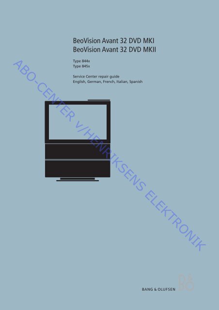
BeoVision Avant 32 DVD MKI<br />
BeoVision Avant 32 DVD MKII<br />
<strong>ABO</strong>-<strong>CENTER</strong> v/<strong>HENRIKSENS</strong> <strong>ELEKTRONIK</strong><br />
Type 844x<br />
Type 845x<br />
Service Center repair guide<br />
English, German, French, Italian, Spanish
CONTENTS<br />
Survey of modules .............................................................................. 1.1<br />
How to service .................................................................................... 1.2<br />
Specification guidelines for service use ................................................. 1.4<br />
Type survey ......................................................................................... 1.9<br />
Warnings .......................................................................................... 1.10<br />
<strong>ABO</strong>-<strong>CENTER</strong> v/<strong>HENRIKSENS</strong> <strong>ELEKTRONIK</strong><br />
Brief operation guide ................................................................................... 2<br />
Wiring diagram ............................................................................................. 3<br />
List of available parts .................................................................................... 4<br />
Adjustments etc. ............................................................................................ 5<br />
Illustrations ......................................................................... 5.101 - 5.102<br />
English German French Italian Spanish<br />
Adjustments 5.1 5.21 5.41 5.61 5.81<br />
Repair tips 5.10 5.30 5.50 5.70 5.90<br />
Theft protection 5.18 5.38 5.58 5.78 5.98<br />
Geometry settings 5.20 5.40 5.60 5.80 5.100<br />
Dismantling ................................................................................................... 6<br />
Illustrations ............................................................................. 6.21 - 6.22<br />
English German French Italian Spanish<br />
Dismantling 6.1 6.5 6.9 6.13 6.17<br />
Insulation test ................................................................................................ 7
Survey of modules 1.1<br />
57<br />
58<br />
59<br />
998<br />
3<br />
998<br />
4<br />
<strong>ABO</strong>-<strong>CENTER</strong> v/<strong>HENRIKSENS</strong> <strong>ELEKTRONIK</strong><br />
6 61*<br />
9<br />
2<br />
74<br />
32<br />
7<br />
42*<br />
20*<br />
10<br />
8<br />
1<br />
14<br />
85*<br />
5<br />
63<br />
* = Optional<br />
45<br />
75<br />
60<br />
80<br />
81<br />
PCB1, 2, 3, 4, 5, 6, 7, 8, 14, 45, 63 999 Main chassis modules (PCB8 not possible if PCB42 is mounted)<br />
PCB9<br />
PCB10<br />
PCB20<br />
PCB32<br />
PCB42<br />
PCB57, PCB58, PCB59<br />
PCB60<br />
PCB61, PCB85<br />
PCB74<br />
PCB75<br />
PCB80, PCB81<br />
PCB998<br />
EFC module<br />
Sound output module<br />
Satellite module<br />
AC3 module<br />
PIP/Feature box Interface module (not possible if PCB8 is mounted)<br />
Display panel<br />
Mains distribution<br />
STB Controller modules<br />
DVD Power Supply module<br />
DVD SMPS module<br />
Motor stand modules<br />
DVD chassis
1.2 How to service, English-German-French<br />
How to service<br />
BeoVision Avant 32 DVD is supposed to be serviced in the customers home!<br />
In order to support the general service strategy, a Back-up suitcase is available which<br />
contains the TV chassis and additional modules.<br />
With this it is possible to easily carry out service in the customers home. Feature<br />
modules are included.<br />
If the TV chassis is replaced, leave the EEPROM in the set. The chip is located on a<br />
separate very small module.<br />
By doing so, the entire identity of the set is maintained.<br />
After having replaced the faulty chassis, please read out error codes, write them<br />
down and let them follow the chassis going for repair.<br />
After that clear error codes.<br />
<strong>ABO</strong>-<strong>CENTER</strong> v/<strong>HENRIKSENS</strong> <strong>ELEKTRONIK</strong><br />
A manual containing block diagrams, schematic diagrams, PCB drawings and list<br />
of electrical parts can be ordered (part no. 3538975).<br />
This manual makes it possible to replace electrical components.<br />
Serviceanleitung<br />
Das BeoVision Avant 32 DVD ist für den Service beim Kunden konzipiert!<br />
Zur Unterstützung der allgemeinen Servicestrategie steht ein Servicekoffer zur<br />
Verfügung, der das TV-Chassis und weitere Module enthält.<br />
Hiermit kann der Service beim Kunden einfach durchgeführt werden. Module für<br />
Spezialfunktionen sind im Koffer enthalten.<br />
Bei Austausch des TV-Chassis muss das EEPROM im Gerät bleiben. Der Chip befindet<br />
sich auf einem sehr kleinen separaten Modul.<br />
Durch Beibehalten des EEPROM bleiben alle gespeicherten Gerätedaten erhalten.<br />
Nach dem Austausch des defekten Chassis bitte die Fehlercodes auslesen, notieren<br />
und dem zur Reparatur eingeschickten Chassis beilegen.<br />
Anschließend die Fehlercodes löschen.<br />
Es kann eine Anleitung mit Blockschaltbildern, Schaltplänen, PCB-Layouts und<br />
einer Stückliste elektrischer Bauteile bestellt werden (Bestell-Nr. 3538975).<br />
Diese Anleitung ermöglicht den Austausch elektrischer Bauteile.<br />
Comment effectuer la maintenance<br />
La maintenance du BeoVision Avant 32 DVD est supposée être effectuée chez le<br />
client !<br />
Afin d’assurer la stratégie de service général, une valise de sauvegarde contenant<br />
le châssis du téléviseur et des modules supplémentaires est disponible.<br />
Ce matériel permet d’effectuer facilement l’intervention sur site chez le client. Des<br />
modules de fonction sont inclus.<br />
En cas de remplacement du châssis du téléviseur, laisser l’EEPROM dans le téléviseur.<br />
La puce se situe sur un tout petit module séparé.<br />
Procéder ainsi permet de maintenir l’identité intégrale du téléviseur.<br />
Après avoir remplacé le châssis défectueux, veuillez faire une lecture des codes<br />
d’erreur, les noter et les transmettre avec le châssis envoyé pour réparation.<br />
Ensuite, effacez les codes d’erreur.<br />
Il est possible de commander un manuel contenant des schémas fonctionnels, des<br />
représentations graphiques schématiques, des dessins de PCB et des listes de<br />
pièces électriques (réf. n° 3538975).<br />
Ce manuel permet de procéder au remplacement de composants électriques.
How to service, Italian-Spanish 1.3<br />
Modalità dell’assistenza<br />
BeoVision Avant 32 DVD è stato concepito per poter essere riparato presso il<br />
domicilio del cliente!<br />
A sostegno della strategia generale sulla quale si basa il servizio di assistenza, viene<br />
messa a disposizione una valigetta di back-up, contenente lo chassis TV, nonché<br />
moduli supplementari.<br />
Questa strumentazione consente di effettuare agevolmente le riparazioni,<br />
direttamente a casa del cliente. Sono compresi anche moduli per le funzioni speciali.<br />
Qualora venga sostituito lo chassis TV, occorrerà lasciare la EEPROM nel set. Il chip<br />
si trova su di un modulo molto piccolo, a parte.<br />
Attenendosi a queste istruzioni, verrà preservata l’identità del set nel suo complesso.<br />
Dopo aver sostituito lo chassis difettoso, leggere i codici di errore, annotarli ed<br />
allegarli allo chassis inviato in riparazione.<br />
Cancellare quindi i codici di errore.<br />
<strong>ABO</strong>-<strong>CENTER</strong> v/<strong>HENRIKSENS</strong> <strong>ELEKTRONIK</strong><br />
È possibile richiedere un manuale completo di diagrammi a blocchi, diagrammi<br />
schematici, schemi delle PCB ed elenco delle parti elettriche (n° serie 3538975).<br />
Con l’ausilio del presente manuale sarà possibile sostituire i componenti elettrici.<br />
Cómo realizar el servicio<br />
El servicio del BeoVision Avant 32 DVD se debe realizar en el domicilio del cliente.<br />
En apoyo de la estrategia general de servicio, hay una maleta auxiliar que contiene<br />
el chasis del televisor y módulos adicionales.<br />
De este modo, se puede realizar fácilmente el servicio en el domicilio del cliente.<br />
Se incluyen módulos de funciones.<br />
Si sustituye el chasis del televisor, deje la EEPROM en el aparato. El chip está ubicado<br />
en un módulo separado muy pequeño.<br />
Haciendo esto, se mantiene la identidad total del aparato.<br />
Después de haber sustituido el chasis defectuoso, lea los códigos de error, anótelos<br />
y adjúntelos con el chasis para su reparación.<br />
A continuación, borre los códigos de error.<br />
Se puede solicitar un manual que contiene diagramas de bloque, diagramas<br />
esquemáticos, diagramas del PCB y una lista de los componentes eléctricos (pieza<br />
número 3538975).<br />
Este manual posibilita la sustitución de los componentes eléctricos.
1.4 Specification guidelines for service use<br />
SPECIFICATION GUIDELINES FOR SERVICE USE<br />
CTV<br />
CTV system<br />
Dimensions W x H x D/Weight<br />
BeoVision Avant 32 DVD<br />
* See type survey<br />
84 x 109 x 61 cm / 86 kg<br />
Cabinet finish<br />
Black, silver, red, green, blue<br />
Power consumption<br />
Typical 134 watt/stand-by < 2 watt<br />
Terminal included<br />
Beo4<br />
Stand turning function<br />
±35 degrees, remote operated, two memory positions<br />
Picture tube/Visual picture 81 cm - 32”/76 cm - 30” (16:9)<br />
Wide-Screen, Real Flat<br />
Curtain<br />
Electronic<br />
Contrast screen<br />
Anti-reflex coating<br />
VisionClear<br />
Auto picture adjustment<br />
Auto cut-off<br />
Digital CTI<br />
Adaptive Luminance Peaking<br />
Scan Velocity Modulation<br />
Improved letterbox<br />
Motion Clear<br />
Teletext<br />
Teletext level 2½, 1780 pages<br />
Wide Screen Signalling (WSS)<br />
Fastext (FLOF), 4 memory pages per program<br />
17 teletext languages in 7 groups<br />
Group 0 English, German, Swedish, Italian, French, Spanish/Portuguese,<br />
Czech/Slovak<br />
Group 1 Polish, German, Swedish, Italian, French, Serbocroat, Czech/Slovak,<br />
Romanian<br />
Group 2 English, German, Swedish, Italian, French, Spanish/Portuguese, Turkish<br />
(Russian) Group 3 English, Russian, Estonian, Czech/Slovak, German, Lithuanian/Lettish,<br />
Ukrainian<br />
(Greece) Group 4 English, German, Swedish, Italian, French, Spanish/Portuguese,<br />
Turkish, Greek<br />
(Arabic) Group 5 English, Arabic, French<br />
(Hebrew) Group 6 English, Hebrew, Arabic<br />
Tuning<br />
Autotune, program move and semiautomatic naming<br />
Tuner range<br />
45 - 860 MHz, VHF, S, Hyper, UHF<br />
TV programmes 99<br />
Stereo decoders<br />
A2 + Nicam<br />
Theft protection<br />
With pin-code or Disabled<br />
<strong>ABO</strong>-<strong>CENTER</strong> v/<strong>HENRIKSENS</strong> <strong>ELEKTRONIK</strong><br />
DVD<br />
Built-in<br />
Disc sizes 12 cm - 5”<br />
Frequency range<br />
20Hz - 20kHz<br />
Playback the following:<br />
DVD-Video, Video CD, CD-A, CD-R, CD-RW<br />
Multistandard PAL/NTSC<br />
Signal-to-noise-ratio<br />
Typical 100 dB, A weighted, in Audio mode<br />
DVD Zone<br />
According to type<br />
Loudspeakers<br />
Power amplifier modules<br />
4 units<br />
Long term max. output power per module<br />
39 watts<br />
Frequency range<br />
50 - 20,000Hz<br />
Max. sound pressure level<br />
96 dB<br />
Cabinet principle/ net volume<br />
Bass Reflex / 3.5 litres<br />
Woofer 115 mm - 4½”<br />
Tweeter 18 mm - 3/4”<br />
Bass equalizer<br />
Adaptive<br />
Magnetic shielded<br />
Yes
Specification guidelines for service use 1.5<br />
Dolby® Digital Decoder<br />
Decoding capabilities<br />
Calibration<br />
Sound modes (Speaker 1 - 5)<br />
Dolby® Digital 5.1 channel decoding<br />
Dolby® Pro-Logic decoding of two channel Dolby® Digital<br />
Dolby® Pro-Logic decoding of two channel PCM<br />
Dolby® Pro-Logic decoding of two analogue channels (Lt/Rt)<br />
Automatic format detection(Dolby® Digital, PCM)<br />
3 channel tone control & loudness (L/C/R)<br />
Bass management, Delay management<br />
Speaker 1 : Stereo internal speakers (subwoofer muted)<br />
Speaker 2 2.0/2.1 : Stereo external speakers / Stereo external<br />
speakers + subwoofer<br />
Speaker 3 3.0/3.1 : Dolby®-3 stereo / Dolby®-3 stereo + subwoofer<br />
Speaker 4 4.0/4.1 : Stereo-4 / Stereo-4 + subwoofer<br />
Speaker 5 5.0/5.1 : Dolby® Digital or Dolby® Pro-Logic Surround /<br />
Dolby® Digital + subwoofer<br />
<strong>ABO</strong>-<strong>CENTER</strong> v/<strong>HENRIKSENS</strong> <strong>ELEKTRONIK</strong><br />
Connections<br />
Digital audio input<br />
2 x Coax phono, Input-1 for AV-scart, Input-2 for DECODER-scart<br />
External BeoLab loudspeakers 5 x Power Link (left, right, rear left, rear right, subwoofer -<br />
internal center)<br />
Loudspeakers recommended, Front/Rear BeoLab 1, BeoLab 8000, BeoLab 6000, BeoLab 4000, BeoLab 4500<br />
Loudspeaker recommended, subwoofer BeoLab 2<br />
System modulator<br />
Frequency range<br />
Audio<br />
Connection<br />
Satellite modul (optional)<br />
Tuner range<br />
Programmes<br />
Sound systems<br />
Satellite radio<br />
Down conv. supply<br />
Connections<br />
Set Top Box-Controller (optional)<br />
Controlling boxes with Beo4<br />
Controlling one or two boxes (2 x STB)<br />
Connection<br />
Splitter/system modulator output to link room<br />
(BeoLink Video Distribution)<br />
479 - 831 MHz (in 1 MHz step), Dual side band<br />
Mono<br />
According to type : FM sound system G : 5.5MHz,<br />
FM sound system I : 6MHz<br />
1 x 75 ohm aerial male<br />
950 - 2150 MHz<br />
119 TV/Radio<br />
Mono/Stereo<br />
Yes<br />
14/18 Volts control, Tone control (22 KHz)<br />
DiSEqC (One way control)<br />
2 x F-connector (2 x 75 ohm)<br />
Supported boxes : See list at Bang & Olufsen Retail System (via internet)<br />
1 box control by use of the IR-blaster included in the kit<br />
2 box control by use of the IR-blaster included in the kit and<br />
IR Y-adaptor (6174171) and one more IR-blaster (8330352)<br />
1 x stereo mini jack
1.6 Specification guidelines for service use<br />
Connections<br />
TV Input<br />
1 x 75 ohms aerial female<br />
System modulator<br />
1 x 75 ohms aerial male (splitter/system modulator output)<br />
According to type : G or I RF output<br />
V.TAPE - AV - Decoder<br />
3 x 21-pin sockets<br />
V.TAPE : CVBS in/out, RGB in (automatic 16:9 sense (pin-8), B&O AVL)<br />
AV : CVBS in/out, RGB in, S-VHS in/out (automatic 16:9 sense (pin-8),<br />
automatic S-VHS configuration, B&O AVL)<br />
DECODER : CVBS in/out (automatic 16:9 sense (pin-8))<br />
BeoLink<br />
1 x Master Link<br />
Dolby® Digital<br />
External BeoLab speakers<br />
5 x Power Link (2 x front, 2 x rear, 1 x subwoofer)<br />
Digital audio input<br />
2 x Coax phono, Input-1 for AV-scart, Input-2 for DECODER-scart<br />
Camcorder / Auxiliary 3 x Phono sockets (video in/audio L-R in) *)<br />
S-Video (S-VHS)<br />
1 x Y/C playback 4-pin socket<br />
Headphone socket<br />
1 x Mini jack<br />
V.TAPE DECODER<br />
1 x 21-pin for V.TAPE decoder (video, L, R in/out)<br />
Satellite modul (optional)<br />
2 x F-connector input (2 x 75 ohms)<br />
STB-Controller output (optional)<br />
1 x Mini jack (stereo for 2 x IR-blaster with IR-Y-adaptor)<br />
<strong>ABO</strong>-<strong>CENTER</strong> v/<strong>HENRIKSENS</strong> <strong>ELEKTRONIK</strong><br />
*) Possible to configure Set Top Box (STB) at Camcorder input and control via STB-Controller<br />
Link Compatibility<br />
Master Link<br />
Optional features/modules<br />
Satellite 4158<br />
Picture in picture 4007<br />
Set Top Box-Controller 4167<br />
Positioner (external)<br />
4170 (EU) 4171 (GB)<br />
Power positioner (external)<br />
4172 (EU) 4173 (GB)<br />
Subject to change without notice
1.8 Specification guidelines for service use<br />
MASTER LINK Pin 1 Data- -0.25V ±0.1V<br />
Pin 2<br />
Pin 3<br />
Data+ +0.25V ±0.1V<br />
ML sense<br />
<strong>ABO</strong>-<strong>CENTER</strong> v/<strong>HENRIKSENS</strong> <strong>ELEKTRONIK</strong><br />
Pin 4-10<br />
Pin 11<br />
Pin 12<br />
Pin 13<br />
Pin 14<br />
Pin 15<br />
Pin 16<br />
N.C.<br />
-supply voltage -7V to -15V (in standby -3V to -15V)<br />
+supply voltage +7V to +15V (in standby +3V to +15V)<br />
Audio -L 1V Bal, Rin 2.2Mohms, Rout 75ohms<br />
Audio +L 1V Bal, Rin 2.2Mohms, Rout 75Mohms<br />
Audio -R 1V Bal, Rin 2.2Mohms, Rout 75ohms<br />
Audio +R 1V Bal, Rin 2.2Mohms, Rout 75ohms<br />
S-VHS Pin 1 Y GND<br />
Pin 2<br />
Pin 3<br />
Pin 4<br />
C GND<br />
Luminance in (Y) 1 Vpp 75 ohms<br />
Chrominance in (C) 1 Vpp 75 ohms<br />
VIDEO<br />
L & R<br />
PHONES<br />
Composite video in 1Vpp 75 ohms<br />
Audio L & R in 0.2V - 2 V RMS >10 kohms<br />
Ø 3.5 mm 220 ohms<br />
POWER LINK FRONT & REAR Pin 1 PL ON = >2.5V, OFF = 2.5V, OFF = 3.5V, Low
Type survey 1.9<br />
*TYPE SURVEY<br />
Modification to other TV transmission<br />
systems (TV only)<br />
Type System Modulator System DVD Zone B/G B/G/L/L’/I/D/K B/G/L/I/M/D/K<br />
8440/8450 B/G EU B/G 2 8000294 8000295<br />
<strong>ABO</strong>-<strong>CENTER</strong> v/<strong>HENRIKSENS</strong> <strong>ELEKTRONIK</strong><br />
8442/8452 I/M/D/K HK I 3 2 8000294 2<br />
8443/8453 I GB I 2 1 1 8000295<br />
8444/8454 B/G ITALY B/G 2 8000294 8000295<br />
8445/8455 B/G AUS B/G 4 8000294 8000295<br />
8446/8456 B/G/D/K EEU B/G 2 1 8000295<br />
8447/8457 B/G/I/M/D/K TAI B/G 3 8000294 2<br />
8448/8458 B/G/L/L’ F(GB) B/G 2 1 8000295<br />
All types mentioned are equipped with PAL/SECAM/NTSC colour decoder.<br />
8000294 Tuner & IF system B/G/L/L’/I/D/K. Can be setup to systems B/G, L/L’, D/K and I in service mode.<br />
8000295 Tuner & IF system B/G/L//I/M/D/K. Can be setup to systems B/G, L, M, D/K and I in service mode.<br />
1 Can be setup to systems B/G, L/L’, D/K and I in service mode.<br />
2 Can be setup to systems B/G, L, M, D/K and I in service mode.<br />
Note:<br />
Modification to other TV systems either by means of Tuner & IF exchange or set up in service mode is only affecting<br />
the TV part and not the modulator. So there might be limitations in functionality changing TV systems.
1.10 Warnings<br />
CAUTION<br />
The use of any controls, adjustments or procedures other than those specified<br />
herein may result in hazardous radiation exposure.<br />
CLASS 1<br />
LASER PRODUCT<br />
COMPACT<br />
DIGITAL VIDEO<br />
COMPACT<br />
DIGITAL AUDIO<br />
<strong>ABO</strong>-<strong>CENTER</strong> v/<strong>HENRIKSENS</strong> <strong>ELEKTRONIK</strong><br />
The black and yellow label on the unit serves as a warning that the apparatus<br />
contains a laser system and is classified as a class 1 laser product. The apparatus<br />
must be opened by qualified service person only.<br />
This product incorporates copyright protection technology that is protected by<br />
claims of certain US patents and other intellectual property rights owned by<br />
technology must be authorized by Macrovision Corporation, and is intended for<br />
home and other limited viewing uses only unless otherwise authorized by<br />
Macrovision Corporation. Reverse enginering or disassembly is prohibited.<br />
Static electricity<br />
STATIC ELECTRICITY<br />
MAY DESTROY THE<br />
PRODUCT<br />
Static electricity may destroy the product!<br />
A static-protective field service kit must always be used when replacecement of the<br />
modules takes place.<br />
Please note:<br />
When mains voltage on the TV is required, remove the connection from the TV to<br />
the ESD mat.<br />
Lithium battery<br />
WARNING<br />
Short-circuit and overcharging of some types of lithium batteries may result in a<br />
violent explosion.
Brief operation guide 2.1<br />
Brief operation guide<br />
Daily use<br />
- Switch on the BeoVision Avant 32 DVD by choosing the source e.g. TV, DVD,<br />
VTAPE etc.<br />
- Switch off the TV with •. Hold for 3 seconds to switch the entire system into stand-by.<br />
<strong>ABO</strong>-<strong>CENTER</strong> v/<strong>HENRIKSENS</strong> <strong>ELEKTRONIK</strong><br />
- Use m and p to change channel up and down. The buttons 0-9 can also be used.<br />
Format change<br />
- Change the format with LIST (until FORMAT) + 1-3.<br />
Format 1: Change between 4:3 / 14:9 / 15:9 with m and p.<br />
Format 2: 16:9 letterbox format, move the picture up and down with m and p.<br />
Format 3: Real 16:9.<br />
- Format optimize with LIST (until FORMAT) + GO.<br />
Volume and speaker adjust<br />
- Raise and lower volume with r and u. Press both to mute and demute the sound.<br />
- Change between speaker modes with LIST (until SPEAKER) + 1-5.<br />
Source selection<br />
- Use the source buttons, can also be found with LIST (until “SOURCE”) + GO.<br />
Stand<br />
- Turn the TV with LIST (until STAND) + l or n.<br />
Picture in Picture (P-IN-P)<br />
- LIST (until P-IN-P) + “SOURCE”. Change between sources with 0. Change the<br />
position of the small picture with LIST (until P-IN-P) + coloured arrow buttons.<br />
Further information<br />
- Please refer to the Guide and the Reference book for further information regarding<br />
operation of the BeoVision Avant 32 DVD.
2.2 Brief operation guide<br />
Main Menu.<br />
Menu<br />
1 Timer play<br />
2 TV list<br />
3 Sat list<br />
4 Setup<br />
4-1 Tuning.<br />
Tuning<br />
1 TV<br />
2 Sat<br />
3 Link frequency<br />
4-1-1 TV tuning.<br />
TV tuning<br />
1 Edit TV list<br />
2 Add program<br />
3 Auto tuning<br />
4 Manual tuning<br />
<strong>ABO</strong>-<strong>CENTER</strong> v/<strong>HENRIKSENS</strong> <strong>ELEKTRONIK</strong><br />
1 Timer play.<br />
Source Pr Start Stop Date<br />
TV 18 08:00-09:00 7 Mar OK<br />
Press MENU for Timer index<br />
Calls up the menu you must use to<br />
program the timer play/stand-by.<br />
2 TV list.<br />
1 DR 1<br />
2 DR 2<br />
3 TV 2<br />
4 Zulu<br />
5 TV Danmark 1<br />
6 TV Danmark 2<br />
7 . . . . . . . . . .<br />
8 . . . . . . . . . .<br />
9 . . . . . . . . . .<br />
10 . . . . . . . . . .<br />
11 . . . . . . . . . .<br />
12 . . . . . . . . . .<br />
13 . . . . . . . . . .<br />
14 . . . . . . . . . .<br />
15 . . . . . . . . . .<br />
16 . . . . . . . . . .<br />
17 . . . . . . . . . .<br />
18 . . . . . . . . . .<br />
19 . . . . . . . . . .<br />
3 Sat list.<br />
1 BBC 1<br />
2 BBC 2<br />
3 ITV<br />
4 Sky<br />
5 Super Ch<br />
6 ZDF<br />
7 Children<br />
8 CNN<br />
9 . . . . . . . . . .<br />
10 . . . . . . . . . .<br />
11 . . . . . . . . . .<br />
12 Eurosport<br />
13 . . . . . . . . . .<br />
14 . . . . . . . . . .<br />
15 MTV<br />
16 . . . . . . . . . .<br />
17 . . . . . . . . . .<br />
18 . . . . . . . . . .<br />
19 . . . . . . . . . .<br />
4 Setup.<br />
Setup<br />
1 Tuning<br />
2 Sound<br />
3 Picture<br />
4 Stand<br />
5 Connections<br />
6 Menu<br />
7 Clock<br />
Calls up the TV<br />
program list.<br />
Calls up the<br />
satellite program<br />
list. This item only<br />
appears if your<br />
BeoVision Avant is<br />
equipped for satellite<br />
TV reception -<br />
if not, SETUP (see<br />
below) will be item<br />
number 4.<br />
4-1-2 Sat.<br />
Sat tuning is used in the same way<br />
as TV tuning.<br />
4-1-3 Link frequency.<br />
Adjustment of system transmission<br />
frequency.<br />
4-2 Sound.<br />
Sound<br />
1 Adjustment<br />
2 Speaker type<br />
3 Speaker distance<br />
4 Speaker level<br />
4-2-1 Adjustment.<br />
Volume Bass Treble Loudness<br />
32 0 0 On<br />
Subwoofer<br />
0<br />
Adjusts the volume, bass, treble,<br />
and turns loudness on/off.<br />
4-2-2 Speaker type.<br />
Front Rear Subwoofer<br />
BeoLab 1 BeoLab 6000 Yes<br />
Choose front and rear speaker types,<br />
and if a subwoofer is connected.<br />
4-2-3 Speaker distance.<br />
Front TV Front<br />
1 meter 1 meter 1 meter<br />
Rear<br />
Rear<br />
1 meter 1 meter<br />
Distance to viewing position<br />
4-2-4 Speaker level.<br />
Front TV Front<br />
+1 (0) +1<br />
Rear<br />
-1 -1<br />
Press MENU for automatic sequence<br />
Rear<br />
4-1-1-1 Edit TV list.<br />
1 BBC 1<br />
2 BBC 2<br />
3 ITV<br />
4 Sky<br />
5 Super Ch<br />
6 ZDF<br />
7 Children<br />
8 CNN<br />
9 . . . . . . . . . .<br />
10 . . . . . . . . . .<br />
11 . . . . . . . . . .<br />
12 Eurosport<br />
13 . . . . . . . . . .<br />
14 . . . . . . . . . .<br />
15 MTV<br />
16 . . . . . . . . . .<br />
17 . . . . . . . . . .<br />
18 . . . . . . . . . .<br />
19 . . . . . . . . . .<br />
press >> to<br />
move<br />
4-1-1-2 Add program.<br />
Freq<br />
Use m and p<br />
to choose which<br />
program to edit.<br />
Use l and n<br />
to move, and<br />
MENU to delete.<br />
Use GO to edit<br />
the program<br />
name.<br />
44 18<br />
Adds automatically any program<br />
which is not already stored in the<br />
TV list.<br />
Pr<br />
4-1-1-3 Auto tuning.<br />
Freq<br />
44 05<br />
Finds all available channels<br />
automatically and stores them.<br />
Pr<br />
4-1-1-4 Manual tuning.<br />
Freq Pr Name<br />
535 1 DR1 More<br />
Manual tuning. “More” gives access<br />
to the menu below.<br />
Fine Decoder Sound Format<br />
0 Off Stereo 15:9<br />
Fine tuning, decoder on/off, sound<br />
and picture format.<br />
4-3 Picture adjustment.<br />
Brilliance Colour Contrast<br />
32 32 44<br />
4-4 Stand positions.<br />
Stand position<br />
1<br />
Turn TV to preferred position<br />
0 - standby position,<br />
1 - primary viewing, 2 - secondary<br />
Continues on next page ->
4-5 Connections.<br />
V.Tape AV Decoder<br />
V.Tape Decoder2 Decoder1<br />
Choose which equipment is<br />
connected to BeoVision Avant DVD.<br />
Operation panel<br />
PLAY TIMER<br />
VOL<br />
STEP<br />
TV / SAT<br />
DVD<br />
LOAD<br />
4-6 Menu.<br />
Menu reminder<br />
On<br />
Menu help text on/off.<br />
4-7 Clock.<br />
PHONES L R VIDEO S–VHS<br />
Time Date Year Synch Display<br />
9:32 Fri 5 Oct 2001 TV3 Yes<br />
Set time and date. Can be synchronised<br />
with Teletext. Choose if<br />
time should be shown in display.<br />
DIGITAL<br />
PRO LOGIC<br />
TIMER<br />
RECORD<br />
<strong>ABO</strong>-<strong>CENTER</strong> v/<strong>HENRIKSENS</strong> <strong>ELEKTRONIK</strong><br />
Brief operation guide 2.3 2.3 Brief operation guide<br />
2.3<br />
PT<br />
Display<br />
DIGITAL PRO LOGIC TIMER RECORD PT<br />
Customizing the Beo4<br />
- ADD/REMOVE button in the list<br />
• then LIST<br />
LIST (until ADD? or REMOVE?) then GO<br />
LIST (until button to add or remove is displayed) then GO<br />
Repeat to ADD/REMOVE more buttons<br />
- MOVE button position in the list<br />
• then LIST<br />
LIST (until MOVE?) then GO<br />
LIST (until button to move is displayed) then GO or “number”<br />
(GO to place button as “number” 1)<br />
(“number” to place button in desired position)<br />
Repeat to MOVE more buttons<br />
Option programming of the BeoVision Avant 32 DVD<br />
• then LIST<br />
LIST (until OPTION?) then GO<br />
LIST (select V.OPTION, A.OPTION or L.OPTION) then GO<br />
(V.OPTION for BeoVision Avant 32 DVD)<br />
Press 0, 1, 2, 5 or 6 (desired option)<br />
Option 0. Disable the remote control of the BeoVision<br />
Avant 32 DVD<br />
Option 1. Used in one-room setup with BeoVision<br />
Avant 32 DVD alone, or in AV setup with a pair of<br />
speakers connected to the audio system<br />
Option 2. Used in two-room setup or in one-room AV<br />
setup with no speakers connected to the audio system<br />
Option 5. Two IR-eyes in the same link room<br />
Option 6. One IR-eye in the link room
3.1<br />
Wiring diagram 3.1<br />
3.1 Wiring diagram<br />
<strong>ABO</strong>-<strong>CENTER</strong> v/<strong>HENRIKSENS</strong> <strong>ELEKTRONIK</strong><br />
Wiring diagram<br />
}<br />
6277440=MKI<br />
6277600=MKII<br />
6277440=MKI<br />
6277600=MKII}
Wiring diagram<br />
Wiring diagram 3.2 3.2 Wiring diagram<br />
3.2<br />
<strong>ABO</strong>-<strong>CENTER</strong> v/<strong>HENRIKSENS</strong> <strong>ELEKTRONIK</strong>
4.1<br />
List of available parts 4.1<br />
4.1 List of available parts<br />
LIST OF AVAILABLE PARTS<br />
Cabinet<br />
9021<br />
9022<br />
14<br />
14<br />
21<br />
21<br />
9015<br />
Incl. pos. no. 9028<br />
19<br />
7<br />
18<br />
16 47<br />
9<br />
5<br />
998<br />
Incl. pos.<br />
no. 9022<br />
16 47<br />
998<br />
3<br />
21<br />
9034<br />
9<br />
5<br />
9<br />
5<br />
9<br />
5<br />
9<br />
9014<br />
21<br />
9016<br />
8<br />
7<br />
6<br />
9017<br />
9018<br />
9017<br />
9030<br />
9019<br />
9020<br />
9010<br />
See also page 4.5<br />
21<br />
1<br />
1<br />
2<br />
3 4<br />
1 2 4<br />
1<br />
3 4 5<br />
5<br />
8<br />
7<br />
6<br />
10<br />
11<br />
10<br />
29<br />
11 11<br />
10<br />
12<br />
12<br />
15<br />
8<br />
7<br />
13<br />
20<br />
9<br />
6<br />
20<br />
22<br />
5<br />
22<br />
15<br />
75<br />
22<br />
13<br />
22<br />
17<br />
17<br />
15<br />
22<br />
29<br />
29<br />
13<br />
22<br />
22<br />
9027<br />
9028<br />
15 13<br />
9024<br />
90S1<br />
9025<br />
22<br />
9031<br />
9032<br />
9033<br />
21<br />
26<br />
26<br />
17<br />
17<br />
17<br />
17<br />
26<br />
17<br />
17<br />
26<br />
26<br />
21<br />
25<br />
25<br />
25<br />
21<br />
21<br />
27<br />
27<br />
26<br />
9026<br />
9037<br />
9039<br />
9026<br />
9040<br />
9041<br />
9037<br />
9042<br />
9044<br />
9046<br />
9047<br />
21<br />
See also page 4.7<br />
9011<br />
9089<br />
9012<br />
17<br />
17<br />
28<br />
26<br />
W9<br />
9013<br />
60<br />
24<br />
23<br />
23<br />
24<br />
24<br />
23<br />
<strong>ABO</strong>-<strong>CENTER</strong> v/<strong>HENRIKSENS</strong> <strong>ELEKTRONIK</strong><br />
9023<br />
29
<strong>ABO</strong>-<strong>CENTER</strong> v/<strong>HENRIKSENS</strong> <strong>ELEKTRONIK</strong><br />
List of available parts 4.2 4.2 List of available parts<br />
4.2<br />
Cabinet<br />
9010 3320488 Loudspeaker panel, silver<br />
3320471 Loudspeaker panel, black<br />
3320476 Loudspeaker panel, red<br />
3320487 Loudspeaker panel, blue<br />
3320475 Loudspeaker panel, green<br />
9011 2732128 O-ring<br />
9012 3458903 Base cover plate<br />
9013 2569694 Profile, silver<br />
2569693 Profile, black<br />
2569691 Profile, red<br />
2569690 Profile, blue<br />
2569692 Profile, green<br />
9014 3151620 Holder<br />
9015* 3320629 Wall, silver - incl. pos. no. 9028<br />
3320631 Wall, black - incl. pos. no. 9028<br />
3320630 Wall, red - incl. pos. no. 9028<br />
3320627 Wall, blue - incl. pos. no. 9028<br />
3320628 Wall, green - incl. pos. no. 9028<br />
9016 3320513 Frame<br />
9017 3151682 Holder f/picture tube<br />
9018 8200113 Picture tube MKI<br />
8200126 Picture tube MKII<br />
9019 3451698 Antireflex coated contrast screen<br />
3451750 Contrast screen without antireflex<br />
9020 3151377 Holder f/picture tube<br />
9021 3131471 Top cover<br />
9022 3151646 Clamper<br />
9023 3151623 Holder and lid f/PCB60<br />
9024 3151490 Holder f/main switch<br />
9025 2776517 Push button f/main switch<br />
9026 2953007 Guide rail f/back cover<br />
9027 3302622 Screen<br />
9028 3151700 Spacer<br />
9030 3162574 Cover f/main switch<br />
9031 3152950 Holder<br />
9032 3152950 Holder<br />
9033 3454871 Frame<br />
9034 3431324 Back cover, upper<br />
9037 2953005 Guide rail f/back cover<br />
9039 3152957 Cable holder<br />
9040 3162721 Holder f/scart plug<br />
9041 3152958 Cable holder<br />
9042 3430803 Back cover, lower<br />
9044 3152964 Guide rail, left<br />
9046 3152963 Guide rail, right<br />
9047 3152996 Holder f/chassis<br />
9089 8053417 Motorized base plate, complete<br />
90S1 7450100 Main switch<br />
W9 6100325 Mains lead w/filter<br />
6100404 Mains lead GB<br />
6100248 Mains lead AUS<br />
03Module 8000297 PCB3, Video Output<br />
09Module 8005417 PCB9, Earth Field Compensation<br />
60Module 8000309 PCB60, Mains Distribution<br />
75Module 8000638 PCB75, DVD SMPS<br />
998Module 8053473 DVD chassis incl. pos. no. 9022<br />
8053518 DVD chassis SD3 for type 845x incl. pos. no. 9022<br />
Survey of screws etc. 1 2076013 Screw<br />
2 2622498 Washer<br />
3 3937082 Bushing<br />
4 2930121 Rubber bushing<br />
5 2019021 Screw 4 x 12mm<br />
6 2058024 Screw 8 x 35mm<br />
7 2624065 Washer<br />
8 2622362 Washer<br />
9 2627023 Washer<br />
10 2052005 Screw 4 x 25mm<br />
11 3152827 Wire holder<br />
12 3151497 Wire holder<br />
13 2038103 Screw 3 x 12mm<br />
14 2036064 Screw 2.5 x 5mm (not always mounted)<br />
15 2622530 Washer<br />
16 2624067 Washer<br />
17 2015156 Screw 3.5 x 12mm<br />
18 2058054 Screw 8 x 30mm<br />
19 2630057 Special washer<br />
20 3152952 Holder<br />
21 2052002 Screw 50 x 27mm<br />
22 2046039 Screw 6 x 18mm<br />
23 2046037 Screw 6 x 40mm<br />
24 3947565 Wafer<br />
25 2013137 Screw 3 x 10mm<br />
26 3152995 Wire holder<br />
27 2938313 Rubber bushing<br />
28 3152986 Wire holder<br />
29 2015163 Screw 4 x 20mm<br />
47 2042074 Screw 4 x 8mm<br />
* Lacquer code nos.<br />
for Wall pos. no. 9015<br />
Colour: Silver<br />
Colour code: Dupont AB BO941<br />
Lacquer: Centari 600<br />
Tone Colour 1 litre<br />
AM 13 242.6<br />
AM 7 281.6<br />
AM 15 313.0<br />
AM 90 315.6<br />
AM 5 325.6<br />
AB 150 966.0<br />
Colour: Black<br />
Colour code: Dupont AB HO697<br />
Lacquer: Centari 600<br />
Tone Colour 1 litre<br />
AM 5 127.3<br />
AM 73 144.9<br />
AB 150 552.9<br />
AB 160 928.2<br />
Colour: Green<br />
Colour code: Dupont AB 7S103<br />
Lacquer: Centari 600 pearl<br />
Tone Colour 1 litre<br />
AM 30 212.4<br />
AM 27 373.4<br />
AM 5 402.4<br />
AM 74 426.5<br />
AM 14 450.2<br />
AM 46 455.1<br />
AB 150 945.9<br />
Colour: Red<br />
Colour code: Dupont AB 3S104<br />
Lacquer: Centari 600 pearl<br />
Tone colour 1 litre<br />
AM 66 119.4<br />
AM 72 233.6<br />
AM 5 285.0<br />
AM 58 291.0<br />
AM 10 291.8<br />
AB 150 947.0<br />
Colour: Blue<br />
Colour code: Dupont AB BO944<br />
Lacquer: Centari 600<br />
Tone colour 1 litre<br />
AM 27 224.0<br />
AM 74 307.0<br />
AM 21 373.4<br />
AM 62 403.4<br />
AM 46 407.4<br />
AM 5 412.4<br />
AM 20 452.4<br />
AB 150 945.0<br />
symbol of safety component, see page 3.1
4.3<br />
List of available parts 4.3<br />
4.3 List of available parts<br />
<strong>ABO</strong>-<strong>CENTER</strong> v/<strong>HENRIKSENS</strong> <strong>ELEKTRONIK</strong><br />
El-chassis<br />
9035 3151689 Holder f/PCB10<br />
9036 3031702 Bracket<br />
9060 3162804 Cover f/display<br />
9061 3160072 Cover f/camcorder<br />
9062 2776398 Set of buttons<br />
9063 2572049 Spacer<br />
9064 3131443 House f/display<br />
9065 3152992 Service strap<br />
9066 3152970 Holder f/PCB’s<br />
9067 3151555 Holder f/Feature box<br />
9068 3151675 Wire holder<br />
9069 3320240 Frame f/chassis<br />
9070 3151491 Holder f/90R1<br />
9071 3152992 Service strap<br />
9074 3151371 Holder f/MKI<br />
3151731 Holder f/MKII<br />
9075 3031556 Ground spring<br />
9076 3152969 Holder f/PCB4 and PCB5<br />
63Module 8008515 PCB63, Modulator B/G<br />
8008681 PCB63, Modulator I<br />
W35 6270739 Coax cable<br />
74Module 8000635 PCB74, DVD Power Supply<br />
85Module 8008903 PCB85, Jack f/STB Controller<br />
Screws etc. 25 2013137 Screw 3 x 10mm<br />
35 2052010 Screw 50 x 12mm<br />
36 2013153 Screw 3 x 6mm<br />
37 2013220 Screw 2.5 x 10mm<br />
38 2380145 Nut f/mini jack socket<br />
39 2013147 Screw 3 x 5mm<br />
56 2015146 Screw 4 x 10mm<br />
57 2019020 Screw 4 x 10mm<br />
W57 6270805 Coax cable SAT 260mm<br />
W58 6270728 Coax cable SAT 230mm<br />
01Module 8000293 PCB1, Tuner/IF & Nicam B/G<br />
8000294 PCB1, Tuner/IF & Nicam B/GL/L’/I/D/K<br />
8000295 PCB1, Tuner/IF & Nicam B/G/M/I/D/K/L<br />
Display & IR<br />
PCB57-PCB58-PCB59<br />
3131480 Display & IR<br />
02Module 8000634 PCB2, Video/Chroma (incl. PCB7)<br />
04Module 8000298 PCB4, Main Power Supply<br />
05Module 8000300 PCB5, Deflection & EHT<br />
8000919 PCB5, Deflection & EHT MKII<br />
5T1 8014218 EHT transformer f/MKI incl. Focus cable, EHT cable,<br />
Focus potentiometer and transformer<br />
8014235 EHT transformer f/MKII incl. EHT cable and transformer<br />
(Focus potentiometer is build into the transformer)<br />
06Module PCB6, Main Microcomputer - see chapter 5 Repair tips<br />
6IC3*∆ 8344093 Software EPROM (must be version 8.5 or higher for MKII)<br />
6IC6∆ 8343984 EEPROM<br />
07Module 8000302 PCB7, Teletext<br />
08Module 8000303 PCB8, Feature box Interface<br />
10Module 8000631 PCB10, Sound Output<br />
14Module 8000632 PCB14, AV Switch (incl. PCB6 - see chapter 5 Repair tips)<br />
1402 3162339 Lid f/PCB6<br />
1403 3151372 Holder f/MKI<br />
3151730 Holder f/MKII<br />
Chassis module 999 & back-up suitcases for MKI type 844x<br />
Chassis module 999 & back-up suitcases for MKII type 845x<br />
Markets Type Chassis Back-up<br />
module 999 suitcase<br />
A-B-CH-D-DK-E-GR-N- B/G with B/G modulator 8053468 3395193<br />
NL-P-S-SF-I-NZ-AUS<br />
UK B/G/L/L’/I/D/K with I modulator 8053469 3395194<br />
EEU-HUN-Thailand B/G/M/I/D/K/L with B/G modulator 8053470 3395196<br />
HK B/G/M/I/D/K/L with I modulator 8053472 3395197<br />
F-CH-B-Channel Islands B/G/L/L’/I/D/K with B/G modulator 8053471 3395195<br />
Markets Type Chassis Back-up<br />
module 999 suitcase<br />
A-B-CH-D-DK-E-GR-N- B/G with B/G modulator 8053513 3395211<br />
NL-P-S-SF-I-NZ-AUS<br />
UK B/G/L/L’/I/D/K with I modulator 8053514 3395212<br />
EEU-HUN-Thailand B/G/M/I/D/K/L with B/G modulator 8053516 3395214<br />
HK B/G/M/I/D/K/L with I modulator 8053517 3395215<br />
F-CH-B-Channel Islands B/G/L/L’/I/D/K with B/G modulator 8053515 3395213<br />
20Module 8008989 PCB20, Satellite<br />
32Module 8000910 PCB32, AC3<br />
3201 3151572 Holder<br />
3202 3151570 Holder f/PCB32<br />
42Module 8000307 PCB42, PIP/Feature box Interface<br />
45Module 8006682 PCB45, Featurebox<br />
57Module 8008372 PCB57, Operation Panel<br />
58Module 8000310 PCB58, Display & IR<br />
58DP2 8330346 LED display<br />
* specially selected or adapted sample<br />
∆ indicates that static electricity may destroy<br />
the component<br />
59Module 8008855 Camcorder Interface & Headphone<br />
61Module 8005946 PCB61, STB Controller (incl. PCB85)<br />
6101 3151423 Holder f/PCB61
List of available parts 4.4<br />
El-chassis<br />
25<br />
25<br />
25<br />
10<br />
74<br />
25<br />
25<br />
25 25<br />
25<br />
25<br />
37<br />
59<br />
37<br />
57<br />
36 36<br />
3636 36<br />
36<br />
58<br />
35<br />
35<br />
9060<br />
9061<br />
9062<br />
9063<br />
58DP2<br />
9064<br />
9035<br />
56<br />
56<br />
56 56<br />
56<br />
57<br />
57<br />
57<br />
57<br />
36<br />
36<br />
25<br />
25<br />
25<br />
25<br />
25<br />
32<br />
25<br />
3201<br />
3202<br />
9036<br />
9069<br />
25<br />
5T1<br />
9065<br />
6101<br />
61<br />
25<br />
25<br />
25<br />
25<br />
25<br />
25<br />
9070<br />
9068<br />
9071<br />
W58<br />
1402<br />
1403<br />
20<br />
1<br />
25<br />
25<br />
25<br />
7<br />
25<br />
2<br />
25<br />
25<br />
25<br />
14<br />
25 25<br />
25<br />
25<br />
6<br />
39<br />
39<br />
85<br />
63<br />
38<br />
25<br />
25<br />
W57<br />
9074<br />
9075<br />
W35<br />
9076<br />
25<br />
<strong>ABO</strong>-<strong>CENTER</strong> v/<strong>HENRIKSENS</strong> <strong>ELEKTRONIK</strong><br />
9066<br />
45<br />
25<br />
8/42<br />
25<br />
4<br />
25<br />
5T1<br />
9067<br />
25<br />
25<br />
5
4.5 List of available parts<br />
Picture tube<br />
9053<br />
9054<br />
9053<br />
5T1<br />
<strong>ABO</strong>-<strong>CENTER</strong> v/<strong>HENRIKSENS</strong> <strong>ELEKTRONIK</strong><br />
9018<br />
9059<br />
9055<br />
9056<br />
9057<br />
9057<br />
9059<br />
9053<br />
9053<br />
9018 8200113 Picture tube MKI<br />
8200126 Picture tube MKII<br />
9053 3152949 Holder f/degaussing coil<br />
9054 7510053 Ground current<br />
9055 3151673 Holder f/degaussing coil<br />
9056 8022374 Degaussing coil<br />
9057 3152178 Wire holder<br />
9059 3152185 Wire holder<br />
5T1<br />
8014218 EHT transformer f/MKI incl Focus cable, EHT cable,<br />
Focus potentiometer and transformer<br />
8014235 EHT transformer f/MKII incl. EHT cable and transformer<br />
(Focus potentiometer is build into the transformer)
List of available parts 4.6<br />
Sound<br />
9080<br />
46<br />
46<br />
9081<br />
9082<br />
RIGHT<br />
9083<br />
9084<br />
29<br />
46<br />
46<br />
<strong>ABO</strong>-<strong>CENTER</strong> v/<strong>HENRIKSENS</strong> <strong>ELEKTRONIK</strong><br />
9085<br />
46<br />
46<br />
46<br />
9086<br />
9087<br />
9080 3152979 Holder<br />
9081 3430734 Loudspeaker cabinet, left<br />
3430735 Loudspeaker cabinet, right<br />
9082 3333031 Gasket<br />
9083 3152980 Holder<br />
9084 8480261 Bass speaker 4.5”- 8Ω<br />
9085 8480237 Treble speaker 18mm - 8Ω<br />
9086 3333033 Rubber bushing<br />
9087 3333033 Rubber bushing<br />
Survey of screws 29 2015163 Screw 4 x 20mm<br />
46 2019018 Screw 4 x 16mm
4.7 List of available parts<br />
Motorized base plate<br />
9089<br />
9090<br />
9091<br />
47<br />
9092<br />
48<br />
49<br />
47<br />
9095<br />
9093<br />
55<br />
50<br />
51<br />
52<br />
47<br />
47<br />
9096<br />
90M1<br />
47<br />
81<br />
80<br />
9097<br />
9098<br />
9099<br />
90100<br />
90101<br />
9094<br />
47<br />
47<br />
<strong>ABO</strong>-<strong>CENTER</strong> v/<strong>HENRIKSENS</strong> <strong>ELEKTRONIK</strong><br />
90102<br />
90103<br />
Cage f. ball bearing<br />
90104<br />
Shafts<br />
54<br />
53<br />
Incl. pos. nos. 9011,<br />
90106, 90107<br />
90105<br />
53<br />
53 54<br />
90106<br />
53 54<br />
54<br />
53 53<br />
90107<br />
9011<br />
47
List of available parts 4.8<br />
Motorized base plate<br />
9011 2732128 O-Ring<br />
9089 8053417 Motorized base plate, complete<br />
9090 2917030 Ball<br />
9091 3152942 Holder f/balls<br />
9092 2993038 Centre tap<br />
9093 2700128 Gear wheel<br />
9094 3162464 Cover w/plate<br />
9095 2700129 Gear wheel<br />
9096 3152940 Holder f/motor<br />
9097 3152941 Holder f/gear wheel<br />
9098 3472827 Damper f/gear wheel<br />
9099 2700131 Gear wheel<br />
90100 2700132 Gear wheel<br />
90101 2732092 Belt<br />
90102 2700130 Gear wheel f/belt<br />
90103 3472827 Damper f/gear wheel<br />
90104 2752035 Top plate<br />
90105 3454810 Bottom plate<br />
90106 2700133 Gear wheel rim<br />
90107 3152959 Holder f/wire bundle<br />
<strong>ABO</strong>-<strong>CENTER</strong> v/<strong>HENRIKSENS</strong> <strong>ELEKTRONIK</strong><br />
90M1<br />
80Modul<br />
81Modul<br />
8400210 Motor<br />
8008337 PCB80, Motor Stand Control<br />
8008338 PCB81, Motor Stand<br />
Survey of screws etc. 47 2042074 Screw 4 x 8mm<br />
48 2380165 Nut<br />
49 2622500 Washer<br />
50 2036061 Screw 2.6 x 6.5mm<br />
51 2938306 Rubber bushing<br />
52 2930074 Bushing<br />
53 2042073 Screw 4 x 6mm<br />
54 2622467 Washer<br />
55 2622492 Washer<br />
LUBRICATION<br />
Cage for ball bearing 3984057<br />
Full synthetic grease (50g)<br />
Tooths on gear wheel rim 90106 3984049<br />
Barrierta grease L55/3 (25g)<br />
Full periphery of gear wheels 9099 and 90100<br />
Rim of gear wheel 9093<br />
Shafts on 90104 3984051<br />
Barrierta oil IS Fluid (50ml)
4.9 List of available parts<br />
Wire bundles See wiring diagram page 3.1 and 3.2.<br />
The part no. is printed on the diagram above the wire bundle, as shown.<br />
<strong>ABO</strong>-<strong>CENTER</strong> v/<strong>HENRIKSENS</strong> <strong>ELEKTRONIK</strong><br />
Accessories See page 1.6.<br />
Beo4 9002 2776627 Set of buttons<br />
2776628 Set of buttons, type 1625 (I)<br />
9003 8001806 PCB<br />
9006 8700017 Battery, Alkaline<br />
All other parts see service manual part no. 3538840<br />
Parts not shown 3390621 3 holders for scart plugs, screws and extension straps for repacking<br />
3543333 Geometry template<br />
6780146 Video test tape<br />
3629145 IC-pliers<br />
3634060 Tool f/picture tube replacement<br />
3657448 Product cover<br />
3658260 Trolley<br />
Available documentation 3508465 Guide, Danish<br />
3508466 Guide, Swedish<br />
3508467 Guide, Finnish<br />
3508468 Guide, English<br />
3508469 Guide, German<br />
3508470 Guide, Dutch<br />
3508471 Guide, French<br />
3508472 Guide, Italian<br />
3508473 Guide, Spanish<br />
3508474 Guide, Portuguese<br />
3508475 Guide, Russian<br />
3503952 Reference Book, Danish<br />
3503953 Reference Book, Swedish<br />
3503954 Reference Book, Finnish<br />
3503955 Reference Book, English<br />
3503956 Reference Book, German<br />
3503957 Reference Book, Dutch<br />
3503958 Reference Book, French<br />
3503959 Reference Book, Italian<br />
3503960 Reference Book, Spanish<br />
3503961 Reference Book, Portuguese<br />
3503962 Reference Book, Russian
List of available parts 4.10<br />
Supplement new DVD 3504698 Guide<br />
Guide f/Set Top Box Controller 3504589 Guide, Danish<br />
3504590 Guide, Swedish<br />
3504591 Guide, Finnish<br />
3504592 Guide, English<br />
3504593 Guide, German<br />
3504594 Guide, Dutch<br />
3504595 Guide, French<br />
3504596 Guide, Italian<br />
3504597 Guide, Spanish<br />
3504598 Guide, Hebrew<br />
<strong>ABO</strong>-<strong>CENTER</strong> v/<strong>HENRIKSENS</strong> <strong>ELEKTRONIK</strong><br />
Setup Guide f/Satellite 3500755 International<br />
Setup Guide f/External Positioner 3500682 International<br />
On-site service guide 3543349 English, German, French, Italian, Spanish, Danish, Dutch for type 844x MKI<br />
3543368 English, German, French, Italian, Spanish, Danish, Dutch for type 845x MKII<br />
Schematic diagrams 3538975 International
4.11 List of available parts<br />
Packing<br />
9301<br />
9302<br />
9303<br />
9309<br />
<strong>ABO</strong>-<strong>CENTER</strong> v/<strong>HENRIKSENS</strong> <strong>ELEKTRONIK</strong><br />
9304<br />
9310<br />
9305<br />
9311<br />
9306<br />
9302<br />
9307<br />
9308<br />
9301 3392549 Outer carton, top<br />
9302 3396008 Foam packing, set of top and bottom<br />
9303 3917105 Foam foil - 1200 x 600mm<br />
9304 3392550 Outer carton, side<br />
9305 3392555 Masonite - order 2pcs. (AUS-HK)<br />
9306 3917105 Foam foil - 1200 x 600mm<br />
9307 3392549 Outer carton, bottom<br />
9308 3392551 Wooden pallet<br />
3392553 Wooden pallet (AUS)<br />
9309 3392699 Chip board (AUS)<br />
9310 3392550 Outer carton, side<br />
9311 3392556 Masonite - order 2pcs. (AUS-HK)<br />
3946176 Bag w/15m strap and 3 holders
Adjustments, English 5.1<br />
ADJUSTMENTS<br />
Most of the adjustments is made in Service Mode. Below see an overview of the<br />
Service Mode menu.<br />
Service menu<br />
Monitor service menu<br />
Monitor information<br />
1 Monitor<br />
2 TV-tuner<br />
3 DVD<br />
4 Chassis variant<br />
TV service setup<br />
1 Monitor information<br />
2 Service counters<br />
3 Picture adjustments<br />
4 Geometry adjustments<br />
5 Text Registers<br />
6 WSS setting<br />
7 Theft protection setting<br />
8 Video signal info<br />
9 PIP HW correction<br />
(only if PIP is mounted)<br />
10 Degauss position<br />
11 Modulator system<br />
12 Earth field correction<br />
(only in Avant 32 DVD)<br />
Tuner system<br />
AFC<br />
1 On<br />
Low tuning range High tuning range<br />
45 860<br />
Lower band limit Upper band limit<br />
172 450<br />
Vhf-1 const Vhf-2 const Uhf const<br />
161 146 52<br />
DVD region setup<br />
Regioncounter Regionsetup<br />
0 2<br />
WSS setting<br />
WSS<br />
On<br />
06 IC3 (AP) : SW 6.0<br />
06 IC2 (IOP) : SW 20.0<br />
20 IC205 (DiSEqC) : SW 1.2<br />
61 IC5 (STB-C) : SW 3.1<br />
61 IC5 (STB-C) : TABLE 1.6<br />
32 IC607 (AC3) : SW 0.75d<br />
72 IC200 (DVD FEP) : SW 1.1<br />
EEPROM ver. 004<br />
Type no. 8430<br />
Item no. 1838832<br />
Serial no. 12345678<br />
Master code<br />
Stored<br />
Option 1<br />
Clock error .... .....<br />
Last TV error .... .....<br />
.... .....<br />
.... .....<br />
.... .....<br />
.... .....<br />
Last ML/SL error ..<br />
Monitor service counters<br />
Stand-by (days) 0000<br />
Audio mode (days) 0000<br />
Video mode (days) 0000<br />
On/Off (times ★10) 0000<br />
DVD playback (days) 0000<br />
VCD playback (days) 0000<br />
CDAudio playback (days) 0000<br />
DVD Power on (times ★10) 0000<br />
Loader closed (times ★10) 0000<br />
Chassis variant setup<br />
Theft protection setting<br />
Picture adjustments<br />
Internal VCR<br />
No<br />
Theft protection<br />
On<br />
PIP HW correction<br />
Correction<br />
Off<br />
Degauss position<br />
Relative position<br />
-10<br />
<strong>ABO</strong>-<strong>CENTER</strong> v/<strong>HENRIKSENS</strong> <strong>ELEKTRONIK</strong><br />
Geometry adjustments<br />
1 Blanking<br />
2 H-PH XX<br />
3 H-AM XX<br />
4 V-AM XX<br />
5 V-SH XX<br />
6 V-OL XX<br />
7 V-SL XX<br />
8 V-PS XX<br />
9 EW-UC XX<br />
10 EW-LC XX<br />
11 EW-PA XX<br />
12 EW-TZ XX<br />
13 EW-PG XX<br />
14 BOW XX<br />
1 Rdr XX<br />
2 Gdr XX<br />
3 Bdr XX<br />
4 Rcu XX<br />
5 Gcu XX<br />
6 Bcu XX<br />
7 PDL XX<br />
8 Chroma trap<br />
Modulator system<br />
System<br />
BG<br />
Earth field correction<br />
Text Register setup<br />
R01 R02 R03 R04 R05 R06 R07 R08<br />
5 11 0 0 0 0 0 0<br />
R09 R10 Set<br />
0 0 0<br />
1 Top skew 42<br />
2 Bottom skew 42<br />
3 Compensation On
5.2 Adjustments, English<br />
SERVICE ADJUSTMENTS WITH Beo4<br />
See the section “Brief Operation Guide” for general information on operation.<br />
Reset<br />
Set brilliance, colour saturation and contrast to nominal values so that they can be<br />
recalled by means of RESET (perhaps a ADD function).<br />
- Press TV MENU 4 (or 3) then 3<br />
<strong>ABO</strong>-<strong>CENTER</strong> v/<strong>HENRIKSENS</strong> <strong>ELEKTRONIK</strong><br />
Brilliance Colour Contrast<br />
32 32 44<br />
- Adjust by means of l, n, m or p, and back up with STOP. Values can be stored by<br />
means of GO.<br />
Format<br />
BeoVision Avant 32 DVD provides the opportunity to choose from three different<br />
picture formats by means of the Beo4 remote control.<br />
Format 1: For standard 4:3 TV pictures. Three views are available. 15:9, 14:9 and<br />
4:3. Press m or p to toggle between the three views.<br />
Format 2: Letter box formats, the Format Optimize circuit chooses the optimal<br />
format. It is possible to move the picture up or down by pressing m or p.<br />
Format 3: 16:9 wide screen. Format 3 will usually be selected automatically, but it<br />
can be selected manual.<br />
“Picture adjustments” only have to be made in format 1 (15:9).<br />
“Geometry adjustments” have to be made in format 1 (15:9, 14:9, 4:3) and<br />
format 3 (16:9).<br />
Selecting a format:<br />
Press TV and toggle the LIST key until the Beo4 display reads FORMAT, then press<br />
1, 2 or 3 to select a format.<br />
FORMAT 1 (15:9)<br />
FORMAT 3 (16:9)<br />
showing a 4:3 picture<br />
FORMAT 3 (16:9)<br />
showing a 16:9 picture
Adjustments, English 5.3<br />
Service mode<br />
When the desired format has been selected, bring the TV into SERVICE MODE,<br />
thereby gaining access to the Service menu:<br />
- Press TV MENU, and select the Setup line by means of the p key, and then press<br />
GO 0 0 GO.<br />
<strong>ABO</strong>-<strong>CENTER</strong> v/<strong>HENRIKSENS</strong> <strong>ELEKTRONIK</strong><br />
Service menu<br />
1 Monitor<br />
2 TV-tuner<br />
3 DVD<br />
4 Chassis variant<br />
- Press 1 to gain access to adjustments on Monitor.<br />
Monitor service menu<br />
1 Monitor information<br />
2 Service counters<br />
3 Picture adjustments<br />
4 Geometry adjustments<br />
5 Text Registers<br />
6 WSS setting<br />
7 Theft protection setting<br />
8 Video signal info<br />
9 PIP HW correction<br />
(only if PIP is mounted)<br />
10 Degauss position<br />
11 Modulator system<br />
12 Earth field correction<br />
(only in Avant 32 DVD)
5.4 Adjustments, English<br />
ADJUSTMENT GUIDE<br />
Initial settings in order to adjust BeoVision Avant 32 DVD<br />
- Remove AV-plug from the AV Scart socket, if any connected.<br />
- Enter SETUP and select CONNECTIONS. Set V.TAPE for V.TAPE. Press GO and then<br />
EXIT to leave the menu.<br />
- Ensure that the TV is in format 3 (16:9), press LIST (until FORMAT) + 3.<br />
- Remember to reconnect when adjustment is finished.<br />
<strong>ABO</strong>-<strong>CENTER</strong> v/<strong>HENRIKSENS</strong> <strong>ELEKTRONIK</strong><br />
A standard colour test pattern must be connected when making the following<br />
adjustments unless otherwise specified.<br />
Horisontal centre adjustment<br />
Horisontal centre switch 5S1 (placed in coordinate 7E) must be adjusted to the<br />
position left, centre or right. See ➢1.<br />
- Press V.TAPE. The screen should go black. Enter SETUP and select PICTURE. Adjust<br />
BRILLIANCE to maximum value (62). Press EXIT.<br />
- Adjust the switch 5S1 until the best centring is achieved.<br />
Ensure that the switch is in the “click” and not between two positions.<br />
G2 (cut off) adjustment<br />
In order to ensure the right G2 voltage for the picture tube, this must be measured<br />
and adjusted if necessary.<br />
Cover the entire display panel with e.g. a soft cloth to prevent sunlight from<br />
adjusting the contrast. Remove this cover when G2-adjustment is done.<br />
- Press V.TAPE. The screen should go black. Enter SETUP and select PICTURE. Adjust<br />
BRILLIANCE to 32 and CONTRAST to 44 which are the nominal values. Press EXIT.<br />
Adjustment with an oscilloscope (recommended)<br />
- Connect the ground lead from the oscilloscope to GROUND on PCB3.<br />
Measure with the oscilloscope on the cathode of 3D102. Read out the value of<br />
the pulse. Repeat this on 3D202 and 3D302. See ➢2.<br />
- Notice which test point has the highest voltage and place the probe on this.<br />
Adjust by means of the G2 (SCREEN) potentiometer until the pulse is 148V ±3V DC<br />
(absolut maximum).<br />
X=2mS DIV<br />
Y=50V DIV<br />
148V ±3V<br />
Adjustment with a multi-meter (Ri > 1 Mohm)<br />
- Set the multi-meter in a DC-voltage area of minimum 200 V.<br />
- Place the black lead from the multi-meter on GROUND on PCB3.<br />
Place the red lead from the multi-meter on the cathode of 3D102. Read out the<br />
value on the multi-meter. Repeat this on 3D202 and 3D302.<br />
- Notice which test point has the highest DC-voltage and place the red lead on this.<br />
Adjust the voltage to approx. 167V DC by means of the G2 (SCREEN)<br />
potentiometer.<br />
0V
Adjustments, English 5.5<br />
Focus adjustment<br />
- Adjust BRILLIANCE to 32 and CONTRAST to 44 which are the nominal values.<br />
Press EXIT. Connect a crosshatch test pattern with a black background.<br />
- Adjust the horisontal lines, with FOCUS 1 (the red potentiometer), seen in the<br />
middle part of the screen.<br />
Adjust the vertical lines, with FOCUS 2 (the black potentiometer), seen in the<br />
upper left corner of the screen.<br />
Repeat both the vertical and the horizontal adjustment twice. See ➢3.<br />
<strong>ABO</strong>-<strong>CENTER</strong> v/<strong>HENRIKSENS</strong> <strong>ELEKTRONIK</strong><br />
Optimum focus is obtained by starting and finishing the adjustment with FOCUS 1<br />
(the red potentiometer). The picture should be viewed approximately 10cm/4”<br />
from the edge of the screen.<br />
Geometry adjustment<br />
Check all the formats and adjust if necessary.<br />
- Select the format to adjust.<br />
- Enter SETUP and enter SERVICE MENU. Select MONITOR and select GEOMETRY<br />
ADJUSTMENTS.<br />
Select the parameter to change and press GO. Change the parameter setting with<br />
m and p. Press GO when the parameter setting is ok.<br />
Select a new parameter or press STOP to return to MONITOR SERVICE MENU.<br />
Press EXIT to exit the menu.<br />
The following settings are fixed and should not be adjusted.<br />
V-OL (vertical scroll) 33 (15:9) or 31 (14:9, 16:9 and 4:3)<br />
V-PS (vertical s-correction) 5 (15:9 and 14:9) or 4 (16:9 and 4:3)<br />
Vertical shift (V-SH), only format 1 (15:9)<br />
Select Blanking and press m to set to On. Then select and adjust V-SH to centre<br />
the picture on the screen. Remember to set Blanking to Off when done.<br />
Vertical amplitude (V-AM)<br />
Adjust V-AM to correct vertical height of the picture. Pay special attention to the<br />
top part of the picture.<br />
Vertical slope (V-SL), only format 1 (15:9) and format 3 (16:9)<br />
Adjust V-SL to correct vertical height of the picture. Pay special attention to the<br />
bottom part of the picture.<br />
Horisontal phase (H-PH), only format 1 (15:9) and format 3 (16:9)<br />
Adjust H-PH to the correct centring of the picture.<br />
Horisontal amplitude (H-AM)<br />
Adjust H-AM to the correct width of the picture.<br />
East/west parabola (EW-PA)<br />
Adjust the vertical lines to be as straight as possible. Pay special attention to the<br />
middle part of the lines.<br />
East/west upper corner (EW-UC)<br />
Adjust the upper corners to be as straight as possible.<br />
East/west lower corner (EW-LC)<br />
Adjust the lower corners to be as straight as possible.
5.6 Adjustments, English<br />
East/west trapeze (EW-TZ)<br />
Adjust until the distance between the vertical lines are equal at the top and at the<br />
bottom of the picture.<br />
<strong>ABO</strong>-<strong>CENTER</strong> v/<strong>HENRIKSENS</strong> <strong>ELEKTRONIK</strong><br />
East/west parallelogram (EW-PG)<br />
Adjust the vertical lines to be as straight as possible. Pay special attention to the<br />
lower and upper part of the lines.<br />
Horizontal bow (BOW), only format 1 (15:9)<br />
Adjust the vertical lines to be as straight as possible.<br />
EFC adjustment (earth field correction), only in Avant 32 DVD<br />
Please note that this is only necessary if PCB9 has been replaced.<br />
- Select format 3, press LIST (until FORMAT) + 3.<br />
- Enter SETUP and enter SERVICE MENU. Select MONITOR and select Earth field<br />
correction. Ensure that COMPENSATION has been set to ON.<br />
Select the parameter to change and press GO. Change the parameter setting with<br />
l and n. Press GO when the parameter setting is ok.<br />
Select a new parameter or press STOP to return to MONITOR SERVICE MENU.<br />
Press EXIT to exit the menu.<br />
TOP SKEW<br />
Adjust the top horisontal lines to be as straight as possible.<br />
BOTTOM SKEW<br />
Adjust the bottom horisontal lines to as straight as possible.
Adjustments, English 5.7<br />
Picture adjustments<br />
- Press 3 in the Monitor service menu to gain access to picture adjustments:<br />
Picture adjustments<br />
<strong>ABO</strong>-<strong>CENTER</strong> v/<strong>HENRIKSENS</strong> <strong>ELEKTRONIK</strong><br />
1 Rdr XX Red drive 0 - 63<br />
2 Gdr XX Green drive 0 - 63<br />
3 Bdr XX Blue drive 0 - 63<br />
4 Rcu XX Red cut-off balance 0 - 63<br />
5 Gcu XX Green cut-off balance 0 - 63<br />
6 Bcu XX Blue cut-off balance 0 - 63<br />
7 PDL XX Peak Drive Level 0 - 63<br />
8 Chroma trap On/Off<br />
- Picture adjustment shall only be made in format 1/(15:9).<br />
- Connect a standard 4:3 test pattern (e.g. Philips).<br />
- Select picture adjustments with a digit (1 - 8) and adjust by pressing m or p.<br />
During the adjustment procedure it is possible to select a new picture adjustment<br />
by means of l or n. Store the adjustment by pressing GO, and select a new<br />
adjustment or end the menu by pressing STOP. The EXIT key will get you out of<br />
the service menus.<br />
Drive<br />
- Adjust the brilliance to the nominal value: Brilliance 32.<br />
- Remove the colour saturation: 00.<br />
- Adjust the red and green drive (Rdr and Gdr) to correct white level.<br />
- Bdr may be used only if correct adjustment cannot be achieved by means of Rdr<br />
and Gdr.<br />
Cut-off balance<br />
- Adjust the brilliance to the nominal value: Brilliance 32.<br />
- Remove the colour saturation: 00.<br />
- Adjust the red and green cut-off balance (Rcu and Gcu) so that the dark fields in<br />
the test pattern become colourless.<br />
- Bcu may be used only if correct adjustment cannot be achieved by means of Rcu<br />
and Gcu.<br />
Peak Drive Level (PDL)<br />
- Adjust the Peak Drive Level to 20.<br />
Chroma trap<br />
- Default is set to OFF, but if there is a problem with the colour graduation in the<br />
picture, it can be set to ON.<br />
The function is always in use on SECAM systems but it is possible to turn on the<br />
function for both PAL and SECAM systems. In that case set to ON.
5.8 Adjustments, English<br />
Module 10, Output Amplifier<br />
Adjustment of bass/treble speaker level<br />
When replacing module 10, potentiometer 10R402-405 or amplifier 10IC15-16,<br />
read out the adjustment position on the old potentiometers and set the new<br />
potentiometers to the same position. See ➢4.<br />
<strong>ABO</strong>-<strong>CENTER</strong> v/<strong>HENRIKSENS</strong> <strong>ELEKTRONIK</strong><br />
Replacing speaker units:<br />
The new speaker unit will have a rated value stamped on its back, and this value<br />
has to be used when making this adjustment. The outputs shall be adjusted to the<br />
nominal value (0.00 dB) according to the table.<br />
- Connect an audio oscillator to the V.TAPE socket 14P21.<br />
14P21 pin 2 Audio right in<br />
14P21 pin 4 Audio ground<br />
14P21 pin 6 Audio left in<br />
- Press VTAPE and toggle on LIST until the display reads SPEAKER, and then press 1<br />
(Sound mode 1 - internal TV speakers).<br />
- The TV sound controls, Bass, Treble and Balance, must be unregulated (0), and the<br />
loudness must be Off. Press: MENU 4 (or 3) 2 1 and adjust by pressing n, l, p or<br />
m.<br />
- Connect an AF voltmeter to 10P57 pin 1 (right in) or pin 4 (left in) with ground to<br />
pin 2.<br />
- If the level in the treble has to be adjusted, set the signal from the audio oscillator<br />
to 10kHz, and adjust the level at the input to 250mV by means of the audio<br />
oscillator output and volume r or u on Beo4.<br />
- If the level in the bass has to be adjusted, set the signal from the audio oscillator<br />
to 1kHz, and adjust the level at the input to 250mV by means of the audio<br />
oscillator output and volume r or u on Beo4.<br />
- Connect an AF voltmeter across the output of the unit in question (the speaker<br />
units need not to be connected during the adjustment procedure):<br />
Bass: 10P77 pin 1 Bass right out 10R402 See ➢4<br />
10P77 pin 3 Bass right ground<br />
10P78 pin 1 Bass left out 10R404<br />
10P78 pin 3 Bass left ground<br />
Treble: 10P77 pin 2 Treble right out 10R403<br />
10P77 pin 3 Treble right ground<br />
10P78 pin 2 Treble left out 10R405<br />
10P78 pin 3 Treble left ground<br />
- Adjust until the voltage at the speaker output corresponds to the voltage found in<br />
the speaker level table by means of the rated value stamped on the back of the<br />
speaker unit.
Adjustments, English 5.9<br />
Rated value in dB Bass Treble<br />
+2.00 dB 1.57 V 2.04 V<br />
+1.75 dB 1.62 V 2.10 V<br />
+1.50 dB 1.67 V 2.16 V<br />
+1.25 dB 1.71 V 2.23 V<br />
+1.00 dB 1.76 V 2.29 V<br />
+0.75 dB 1.82 V 2.36 V<br />
+0.50 dB 1.87 V 2.43 V<br />
+0.25 dB 1.92 V 2.50 V<br />
0.00 dB 1.98 V 2.57 V<br />
- 0.25 dB 2.04 V 2.65 V<br />
- 0.50 dB 2.10 V 2.72 V<br />
- 0.75 dB 2.16 V 2.80 V<br />
- 1.00 dB 2.22 V 2.88 V<br />
- 1.25 dB 2.29 V 2.97 V<br />
- 1.50 dB 2.35 V 3.05 V<br />
- 1.75 dB 2.42 V 3.14 V<br />
- 2.00 dB 2.49 V 3.24 V<br />
<strong>ABO</strong>-<strong>CENTER</strong> v/<strong>HENRIKSENS</strong> <strong>ELEKTRONIK</strong>
5.10 Repair tips, English<br />
REPAIR TIPS<br />
Service mode<br />
The service mode consists of two parts: Service menu and Bus ignore mode.<br />
<strong>ABO</strong>-<strong>CENTER</strong> v/<strong>HENRIKSENS</strong> <strong>ELEKTRONIK</strong><br />
Service menu<br />
The service menu contains options such as picture and geometry adjustments -<br />
see the section SERVICE ADJUSTMENTS WITH Beo4. In the following description<br />
the Beo4 terminal is used for operating the product.<br />
SERVICE MODE, thereby gaining access to the Service menu:<br />
- Press TV MENU, and select the Setup line by means of the p key, and then press<br />
GO 0 0 GO. It is possible to “go backwards” in the menus by pressing STOP.<br />
Service mode is abandoned by pressing •.<br />
Service menu<br />
1 Monitor<br />
2 TV-tuner<br />
3 DVD<br />
4 Chassis variant<br />
In the service menu you can choose which source you wish to have information on<br />
or wish to adjust/set up.<br />
Select Monitor, press 1<br />
Monitor service menu<br />
1 Monitor information<br />
2 Service counters<br />
3 Picture adjustments<br />
4 Geometry adjustments<br />
5 Text Registers<br />
6 WSS setting<br />
7 Theft protection setting<br />
8 Video signal info<br />
9 PIP HW correction<br />
(only if PIP is mounted)<br />
10 Degauss position<br />
11 Modulator system<br />
12 Earth field correction<br />
(only in Avant 32 DVD)<br />
In the Monitor service menu you can choose among the following items of<br />
information:<br />
(Picture, Geometry adjustments and Earth field correction are described in the<br />
section on adjustments).
Repair tips, English 5.11<br />
Monitor information<br />
Monitor information menu, press 1<br />
Monitor information<br />
<strong>ABO</strong>-<strong>CENTER</strong> v/<strong>HENRIKSENS</strong> <strong>ELEKTRONIK</strong><br />
06 IC3 (AP) : SW 6.0<br />
06 IC2 (IOP) : SW 20.0<br />
20 IC205 (DiSEqC) : SW 1.2<br />
61 IC5 (STB-C) : SW 3.1<br />
61 IC5 (STB-C) : TABLE 1.6<br />
32 IC607 (AC3) : SW 0.75d<br />
72 IC200 (DVD FEP) : SW 2.0<br />
EEPROM ver. 004<br />
Type no. 8430<br />
Item no. 1838832<br />
Serial no. 12345678<br />
Master code<br />
Stored<br />
Option 1<br />
Clock error .... .....<br />
Last TV error .... .....<br />
.... .....<br />
.... .....<br />
.... .....<br />
.... .....<br />
Last ML/SL error ..<br />
- Software version number<br />
20IC205 (DiSEqC), 61IC5 (STB-C) and 32IC607 (AC3) are only shown if the<br />
modules are mounted in the Avant 32 DVD.<br />
61IC5 (STB-C) TABLE indicates the version of the STB-C conversion codes.<br />
Option<br />
Option 0 = The IR reciever of the TV is disconnected.<br />
Option 1 = The TV and the Audio system (BeoLink system) are placed in the same<br />
room.<br />
Option 2 = The TV and the Audio system (BeoLink system) are placed in different<br />
rooms.<br />
Option 5 = The TV and the Audio system (BeoLink system) are placed in the same<br />
link room.<br />
Option 6 = The TV is the only product in the link room.<br />
Important!<br />
When replacing the electrical chassis including PCB6 Main microcomputer, to avoid<br />
loss of data the old EEPROM 6IC6 must be moved to the new PCB6. See ➢6.<br />
If error codes occurs, please write them down and let them follow the faulty part<br />
for repair. After that clear the error codes. This is done by pressing GO in the<br />
Monitor information menu.
5.12 Repair tips, English<br />
Service counters<br />
Monitor service counters<br />
Standby (days) 0000<br />
Audio mode (days) 0000<br />
Video mode (days) 0000<br />
On/off (times *10) 0000<br />
<strong>ABO</strong>-<strong>CENTER</strong> v/<strong>HENRIKSENS</strong> <strong>ELEKTRONIK</strong><br />
DVD playback (days) 0000<br />
VCD playback (days) 0000<br />
CDAudio playback (days) 0000<br />
DVD Power on (times *10) 0000<br />
Loader closed (times *10) 0000<br />
(times *10) = The numbers are stated in interval of 10 (e.g. 10 = 100). The<br />
number is given in full tens. If the number exceeds four digits, the four least<br />
significant digits are shown (e.g. 12834 is shown as 2834).<br />
The other times in the menu are shown in full days.<br />
Text registers<br />
Text Register setup<br />
R01 R02 R03 R04 R05 R06 R07 R08<br />
5 11 0 0 0 0 0 0<br />
R09 R10 Set<br />
0 0 0<br />
Selecting “Set” makes it possible to choce from 7 different teletext character set.<br />
0 1 2 3 4 5 6<br />
English Polish English English English English English<br />
German German German Russian German Arabic Hebrew<br />
Swedish Swedish Swedish Estonian Swedish French Arabic<br />
Italian Italian Italian Czech/Slovak Italian<br />
French French French German French<br />
Portuguese Serbocroat Portuguese Lithuanian/Lettish Portuguese<br />
Czech/Slovak Czech/Slovak Turkish Ukranian Turkish<br />
Rumanian<br />
Greek<br />
Group delay errors in certain cable aerial systems can disturb the reception of<br />
teletext. This is prevented by connecting a filter in series with the CVBS signal<br />
applied to the teletext decoder.<br />
The numbers below the Register numbers R01 - R10 are programme numbers. If<br />
all the numbers are 0, no filter has been connected on any programme number.<br />
If you wish to connect a filter on a programme number, select a register by<br />
pressing l / n, then press the desired programme number, and finally press GO.<br />
In the example above a filter has been connected on programmes 5 and 11. The<br />
filter is not engaged until the next time you switch to the programme in question.
Repair tips, English 5.13<br />
WSS setting<br />
WSS setting<br />
WSS<br />
On<br />
<strong>ABO</strong>-<strong>CENTER</strong> v/<strong>HENRIKSENS</strong> <strong>ELEKTRONIK</strong><br />
Some TV broadcasters transmit a picture format identification, enabling the TV to<br />
switch to the proper format automatically when WSS is On. When WSS is On,<br />
detection is carried out on all picture sources, i.e.<br />
TV tuner, satellite tuner and video/DVD playback.<br />
Under certain conditions, e.g. a poor signal-to-noise ratio, the detection may fail,<br />
which may entail faulty format switching. WSS may therefore be set to “Off”.<br />
WSS may also be set to “Broadcast only”, which means that detection is carried<br />
out only on signals from the TV tuner and the satellite tuner.<br />
Some broadcasters do not send a “WSS Off” signal when one program is finished<br />
and another begins. When the “WSS signal” disappears, then the format will<br />
return to the default.<br />
Theft protection setting<br />
- In this menu it is possible to enable (ON) or disable (OFF) theft protection. It is only<br />
possible to enter this menu if no pin code is set for the Avant 32 DVD.<br />
Video signal info<br />
- In this menu the signal/noise ratio of the tuner input is displayed. The higher the<br />
signal/noise ratio the lower the figure.<br />
PIP HW correction<br />
- Default set to OFF, but if there is a problem with the colours in the PIP picture it<br />
can be set to ON (especially when mixing two TV systems, for example PAL and<br />
SECAM).
5.14 Repair tips, English<br />
DVD region setup<br />
DVD region setup<br />
Regioncounter Regionsetup<br />
1 2<br />
<strong>ABO</strong>-<strong>CENTER</strong> v/<strong>HENRIKSENS</strong> <strong>ELEKTRONIK</strong><br />
Region setup:<br />
Region codes (1 - 11)<br />
To call up the menu press DVD on Beo4 then press LOAD on the operation panel,<br />
(there must be no disc loaded), to close the DVD loader. Enter service mode and<br />
press 3 (DVD). The region setup no. may not always show the correct figure.<br />
If these conditions are not fulfiled this sign will be displayd.<br />
DVD region setup<br />
NOTE!<br />
DVD SOURCE SELECTED<br />
LOADER CLOSED<br />
NO DISC IN DRIVE<br />
Regioncounter:<br />
In this line it is shown how many times the region code has been changed.<br />
Connection between primary/secondary TV colour systems and region codes:<br />
Region 1 Region 2 Region 3 Region 4 Region 5 Region 6<br />
NTSC/PAL 1 7 8 9<br />
PAL/NTSC 2 3 4 5 6<br />
NTSC/PAL N 10<br />
PAL M/PAL 11<br />
IMPORTANT!<br />
The number of times to change the region setting is limited. If this limit is<br />
exceeded the DVD will cease to function!<br />
Region code according to type no.<br />
Type no. Region code<br />
8440 2<br />
8442 3<br />
8443 2<br />
8444 2<br />
8445 4<br />
8446 2<br />
8447 3<br />
8448 2
Repair tips, English 5.15<br />
Degauss position<br />
In this menu it is possible to set up the position (angle) where Avant 32 DVD will<br />
activate its degaussing circuit. The degaussing position is measured and activated<br />
with reference to the stored Position 1 of the turning stand. That is when you turn<br />
on the TV from St.by and you have programmed the TV to turn to the preferred<br />
position, it will start to turn and when it is getting close to the stored position the<br />
TV will start degaussing and continue with the normal start up procedure.<br />
The reason for introducing this setup is that especially the large RF tubes are rather<br />
sensitive to magnetic influence, both from magnetic fields caused by for instance<br />
external loudspeakers, and perhaps especially from the Earth field. This field may<br />
cause colour impurity on the screen.<br />
<strong>ABO</strong>-<strong>CENTER</strong> v/<strong>HENRIKSENS</strong> <strong>ELEKTRONIK</strong><br />
It is important to understand that the setup is a compromise between a short/long<br />
start-up time and best/worst influence from the magnetic fields.<br />
Delaying the start-up procedure (meaning setup of the “Relative position” close to<br />
0) will optimise the purity of the picture but will give the following disadvantages:<br />
- Prolonged start-up time<br />
- The IR will be “blind” to commands while turning the stand and starting up the TV<br />
- In a link system the whole system will be “blind” to commands when the<br />
Avant 32 DVD is starting up, and this applies both if it is placed in the main room<br />
and in the link room<br />
- Choosing V-Tape from st.by will cause the VTR to start playing immediately but<br />
due to the prolonged start-up time the first seconds of the playback will be lost<br />
You can set up values in the “Relative position” menu between 0 and -60, and<br />
each step corresponds to approx. 2 degrees.<br />
Modulator system<br />
Modulator system<br />
System<br />
BG<br />
When replacing the EEPROM 6IC6, PCB6 or PCB14 where PCB6 is mounted, the<br />
modulator system must be set to the correct system BG or I.<br />
Earth field correction<br />
(only Avant 32 DVD)<br />
(Is normally used for adjustment)<br />
Earth field correction<br />
1 Top skew 42<br />
2 Bottom skew 42<br />
3 Compensation On<br />
The Compensation line must always be set to On, but if a faulty geometry in the<br />
picture occurs it can be set to Off, to determine if the fault is in the earth field<br />
compensation circuit or in the deflection circuits.
5.16 Repair tips, English<br />
TV-tuner<br />
Select TV-tuner in the Service menu, press 2<br />
TV service setup<br />
<strong>ABO</strong>-<strong>CENTER</strong> v/<strong>HENRIKSENS</strong> <strong>ELEKTRONIK</strong><br />
Tuner system<br />
AFC<br />
1 On<br />
Low tuning range High tuning range<br />
45 860<br />
Lower band limit Upper band limit<br />
172 450<br />
Vhf-1 const Vhf-2 const Uhf const<br />
161 146 52<br />
In the TV service setup menu it is only the Tuner system and AFC fields that have<br />
to be used. The rest of the fields are for factory usage, and the values in them may<br />
not be changed.<br />
Tuner system:<br />
The digital value in the field stands for the CTV system for which the applicable IF<br />
is intended.<br />
If the Tuner & IF PCB is replaced to permit reception of a different CTV system, the<br />
digital value has to be changed.<br />
The digital values for the various systems are the following:<br />
B/G = 1<br />
L/L’ = 2<br />
M = 4<br />
D/K = 8<br />
I = 16<br />
The digital value for system combinations is obtained by adding the applicable<br />
digits.<br />
The digital values for the IF variants in BeoVision Avant 32 DVD are the following:<br />
B/G = 1<br />
B/G/L/L’ = 3<br />
B/G/D/K = 9<br />
I = 16<br />
B/G/L/L’/I = 19<br />
M/I/D/K = 28<br />
B/G/M/I/D/K = 29<br />
Press GO to save the digital value.<br />
AFC On/Off is used in connection with adjustments but it may also be useful in<br />
other situations. Press l / n to move the cursor.<br />
Press m / p to switch between On/Off.<br />
AFC Off cannot be stored. AFC is always On after stand-by.
Repair tips, English 5.17<br />
Chassis variant<br />
- Chassis variant setup. In BeoVision Avant 32 DVD the line “Internal VCR” must<br />
always be set to No.<br />
Remember to check the line if the EEPROM 6IC6 has been replaced.<br />
<strong>ABO</strong>-<strong>CENTER</strong> v/<strong>HENRIKSENS</strong> <strong>ELEKTRONIK</strong><br />
Bus ignore mode<br />
If an error occurs in the I²C bus system which makes the TV go into stand-by every<br />
time it is attempted to be switched on, it is possible to switch on the TV in such a<br />
way that the error is ignored:<br />
- The TV must be on stand-by for at least 5 seconds.<br />
- Short-circuit the service socket, P84 on AV Switch PCB14, coordinate 5L, for a<br />
minimum of 0.5 second. See ➢5.<br />
- Remove the jumper.<br />
- Press TV. The TV will now start up in the bus ignore mode if that is possible.
5.18 Theft protection, English<br />
THEFT PROTECTION<br />
The theft protection is a 4 digit PIN-code, of the user´s own choice, which must be<br />
entered if the TV has been disconnected from the mains for 15-30 min.<br />
The theft protection is always deactivated from the factory, it is up to the user to<br />
activate it.<br />
If the theft protection is activated, and the TV has been without mains for 15-30 min.,<br />
the user will be asked to enter the 4 digit PIN-code when the TV is switched on.<br />
Before the TV is handed in to service it is a good idea to ask the customer to<br />
deactivate the theft protection.<br />
<strong>ABO</strong>-<strong>CENTER</strong> v/<strong>HENRIKSENS</strong> <strong>ELEKTRONIK</strong><br />
Service code<br />
If the PIN-code is activated and the product is in a service situation, there is a<br />
possibility of 12 hours service by entering a 5 digit Service code which is 1 1 1 1 1.<br />
This gives 12 hours of full functionality to service the product and make module<br />
changes without naming/registering the replaced modules to the customer´s<br />
product. The 12 hours are only running when the product is connected to the<br />
mains!<br />
If the customer´s PIN-code or Master-code is entered the replaced modules will be<br />
named/registered to the product. Registration of the modules cannot be changed.<br />
The Service code can be entered when the TV has been disconnected from the<br />
mains for 15-30 min.<br />
When the TV is switched on a PINCODE menu appears. Now press l (rewind) for<br />
three seconds and a MASTERCODE menu appears, and the Service code 1 1 1 1 1<br />
can be entered, then press GO.<br />
Replacing the Main Microcomputer PCB6<br />
When replacing the electrical chassis including PCB6 remember to move the<br />
EEPROM 6IC6 from the defective PCB6 to the new PCB6, because it contains<br />
valuable data (Serial no., PIN-code etc.).<br />
The data is not transferred to the new module until you have been in contact with<br />
the theft protection or after 12 hours of connection to the mains. This means that<br />
you can try out a new PCB6 without transferring the products serial no. etc.<br />
Note !<br />
If you have tried out a new PCB6 and the serial no. has been transferred to the new<br />
PCB6 and it says that the old PCB6 is not defective, the new PCB6 can only be used<br />
for this specific product, it must be returned to Bang & Olufsen to be erased again.<br />
If the product functions are OK the theft protection is also OK. There is no need<br />
for testing the functionality of the theft protection.<br />
Activate the PIN code system<br />
Select the TV SETUP menu.<br />
Press l twice and then STOP to bring up the PINCODE SETUP menu.<br />
Enter the 4 digit Pin-code. Re-enter the code to confirm it and press GO.<br />
If you want to change or delete the PIN-code, enter the correct PIN-code and press GO.<br />
It is now possible to change the PIN-code or delete the PIN-code.<br />
Enter the PIN code<br />
If the PIN-code system is activated and the TV is disconnected from the mains for<br />
more than15-30 minutes, a PINCODE menu appears as soon as the TV is switched<br />
on.<br />
Enter the PIN-code digits, then the TV starts again.
Theft protection, English 5.19<br />
If the PIN code has been forgotten<br />
If the PIN-code has been forgotten (5 tries within 3 hours with the mains connected),<br />
the only way to unlock the TV again is by entering a 5 digit Master-code.<br />
The Master-code is ordered by sending a request either via the Retail System or on<br />
the Master-code formula. If non of these options are available please contact Bang &<br />
Olufsen.<br />
When the TV prompts for a PIN-code, press and hold l down to bring up the<br />
MASTERCODE menu.<br />
Enter the Master-code and press GO. This will deactivate the PIN-code and<br />
reactivate the TV.<br />
<strong>ABO</strong>-<strong>CENTER</strong> v/<strong>HENRIKSENS</strong> <strong>ELEKTRONIK</strong>
Curtain<br />
28"- 20mm<br />
32"- 23mm<br />
BeoVision Avant RF<br />
FORMAT 1 ( 15:9 )<br />
32"- 28"-<br />
10mm 7mm<br />
32"- 28"-<br />
16mm 16mm<br />
Curtain<br />
28"- 20mm<br />
32"- 23mm<br />
Curtain<br />
28"- 20mm<br />
32"- 23mm<br />
BeoVision Avant RF<br />
FORMAT 1 ( 15:9 )<br />
BeoVision Avant RF<br />
FORMAT 1 ( 15:9 )<br />
32"- 28"-<br />
10mm 7mm<br />
32"- 28"-<br />
16mm 16mm<br />
32"- 28"-<br />
10mm 7mm<br />
32"- 28"-<br />
16mm 16mm<br />
32"- 28"-<br />
16mm 16mm<br />
32"- 28"-<br />
10mm 7mm<br />
FORMAT 1 ( 15:9 )<br />
BeoVision Avant RF<br />
32"- 23mm<br />
Curtain<br />
28"- 20mm<br />
28"- 20mm<br />
32"- 23mm<br />
BeoVision Avant RF<br />
32"-<br />
10mm<br />
28"-<br />
7mm<br />
32"- 28"-<br />
16mm 16mm<br />
5.20 Geometry settings for adjustment, English<br />
Geometry settings for adjustment<br />
23.5mm 23.5m<br />
Curtain<br />
28"- 20mm<br />
FORMAT 1 (15:9)<br />
32"- 23mm<br />
32"-<br />
10mm<br />
28"-<br />
7mm<br />
BeoVision Avant RF<br />
41.5mm<br />
41.5mm<br />
FORMAT 1 (14:9)<br />
FORMAT 1 ( 15:9 )<br />
32"- 28"-<br />
16mm 16mm<br />
28"- 27mm<br />
32"- 35mm<br />
28"-<br />
18mm<br />
32"-<br />
24mm<br />
79.0mm<br />
79.0mm<br />
BeoVision Avant RF<br />
FORMAT 1 (4:3)<br />
FORMAT 3 ( 16:9 )<br />
32"-<br />
22mm<br />
28"-<br />
18mm<br />
Use of geometry template<br />
Curtain<br />
<strong>ABO</strong>-<strong>CENTER</strong> v/<strong>HENRIKSENS</strong> <strong>ELEKTRONIK</strong><br />
1. Place the arrows along the black phosphor edges of the picture tube.<br />
Picture tube<br />
FORMAT 1 ( 15:9 )<br />
Phosphor edge<br />
Black edge of the<br />
contrast screen<br />
Black/grey edge of the<br />
contrast screen<br />
2. Adjust geometry to fit the marked points within the grey area.
Einstellungen, Deutsch 5.21<br />
EINSTELLUNGEN<br />
Die meisten Einstellungen werden im Service-Modus vorgenommen. Hier sehen<br />
Sie eine Übersicht über die Menüs des Service-Modus.<br />
Service menu<br />
Monitor service menu<br />
Monitor information<br />
1 Monitor<br />
2 TV-tuner<br />
3 DVD<br />
4 Chassis variant<br />
TV service setup<br />
1 Monitor information<br />
2 Service counters<br />
3 Picture adjustments<br />
4 Geometry adjustments<br />
5 Text Registers<br />
6 WSS setting<br />
7 Theft protection setting<br />
8 Video signal info<br />
9 PIP HW correction<br />
(only if PIP is mounted)<br />
10 Degauss position<br />
11 Modulator system<br />
12 Earth field correction<br />
(only in Avant 32 DVD)<br />
Tuner system<br />
AFC<br />
1 On<br />
Low tuning range High tuning range<br />
45 860<br />
Lower band limit Upper band limit<br />
172 450<br />
Vhf-1 const Vhf-2 const Uhf const<br />
161 146 52<br />
DVD region setup<br />
Regioncounter Regionsetup<br />
0 2<br />
WSS setting<br />
WSS<br />
On<br />
06 IC3 (AP) : SW 6.0<br />
06 IC2 (IOP) : SW 20.0<br />
20 IC205 (DiSEqC) : SW 1.2<br />
61 IC5 (STB-C) : SW 3.1<br />
61 IC5 (STB-C) : TABLE 1.6<br />
32 IC607 (AC3) : SW 0.75d<br />
72 IC200 (DVD FEP) : SW 1.1<br />
EEPROM ver. 004<br />
Type no. 8430<br />
Item no. 1838832<br />
Serial no. 12345678<br />
Master code<br />
Stored<br />
Option 1<br />
Clock error .... .....<br />
Last TV error .... .....<br />
.... .....<br />
.... .....<br />
.... .....<br />
.... .....<br />
Last ML/SL error ..<br />
Monitor service counters<br />
Stand-by (days) 0000<br />
Audio mode (days) 0000<br />
Video mode (days) 0000<br />
On/Off (times ★10) 0000<br />
DVD playback (days) 0000<br />
VCD playback (days) 0000<br />
CDAudio playback (days) 0000<br />
DVD Power on (times ★10) 0000<br />
Loader closed (times ★10) 0000<br />
Chassis variant setup<br />
Theft protection setting<br />
Picture adjustments<br />
Internal VCR<br />
No<br />
Theft protection<br />
On<br />
PIP HW correction<br />
Correction<br />
Off<br />
Degauss position<br />
Relative position<br />
-10<br />
<strong>ABO</strong>-<strong>CENTER</strong> v/<strong>HENRIKSENS</strong> <strong>ELEKTRONIK</strong><br />
Geometry adjustments<br />
1 Blanking<br />
2 H-PH XX<br />
3 H-AM XX<br />
4 V-AM XX<br />
5 V-SH XX<br />
6 V-OL XX<br />
7 V-SL XX<br />
8 V-PS XX<br />
9 EW-UC XX<br />
10 EW-LC XX<br />
11 EW-PA XX<br />
12 EW-TZ XX<br />
13 EW-PG XX<br />
14 BOW XX<br />
1 Rdr XX<br />
2 Gdr XX<br />
3 Bdr XX<br />
4 Rcu XX<br />
5 Gcu XX<br />
6 Bcu XX<br />
7 PDL XX<br />
8 Chroma trap<br />
Modulator system<br />
System<br />
BG<br />
Earth field correction<br />
Text Register setup<br />
R01 R02 R03 R04 R05 R06 R07 R08<br />
5 11 0 0 0 0 0 0<br />
R09 R10 Set<br />
0 0 0<br />
1 Top skew 42<br />
2 Bottom skew 42<br />
3 Compensation On
5.22 Einstellungen, Deutsch<br />
SERVICE-EINSTELLUNGEN MIT Beo4<br />
Siehe den Abschnitt ‘Brief Operation Guide’ für allgemeine Informationen über die<br />
Bedienung.<br />
Reset<br />
Helligkeit (Brilliance), Farbsättigung (Colour) und Kontrast (Contrast) auf ihre<br />
Nominalwerte einstellen, so daß diese Werte mit der Taste RESET wieder aufrufbar<br />
sind (vielleicht ADD-Funktion).<br />
- Tastenbetätigung: TV MENU 4 (oder 3) 3<br />
<strong>ABO</strong>-<strong>CENTER</strong> v/<strong>HENRIKSENS</strong> <strong>ELEKTRONIK</strong><br />
Brilliance Colour Contrast<br />
32 32 44<br />
- Mit den Tasten l, n, m oder p einstellen, und mit der Taste STOP rückwärtsschalten.<br />
Werte evtl. mit der Taste GO speichern.<br />
Format<br />
BeoVision Avant 32 DVD bietet die Möglichkeit, zwischen drei verschiedenen<br />
Bildformaten mit Hilfe der Beo4-Fernbedienung zu wählen.<br />
Format 1: Für Standard 4:3 TV-Bilder. Es stehen drei Bildgrößen zur Verfügung:<br />
15:9, 14:9 und 4:3.<br />
Drücken Sie m oder p, um zwischen den drei Bildgrößen zu schalten.<br />
Format 2: ‘Letter Box‘-Formate; der ‘Format Optimize‘-Schaltkreis wählt das<br />
optimale Format. Es ist möglich, das Bild mit den Tasten m oder p nach oben oder<br />
nach unten zu verschieben.<br />
Format 3: 16:9 Breitbild (Wide screen). Format 3 wird normalerweise automatisch<br />
gewählt, kann aber auch manuell gewählt werden.<br />
‘Picture adjustments’, d.h. Bildeinstellungen, sind nur in Format 1 (15:9)<br />
durchzuführen.<br />
‘Geometry adjustments’, d.h. Geometrieeinstellungen, sind in Format 1 (15:9,<br />
14:9, 4:3) und Format 3 (16:9) durchzuführen. Anwählen eines Formats:<br />
Drücken Sie TV und betätigen Sie die LIST -Taste so lange, bis im Beo4-Display das<br />
Wort FORMAT erscheint; danach drücken Sie 1, 2 oder 3, um ein Format zu wählen.<br />
FORMAT 1 (15:9)<br />
FORMAT 3 (16:9),<br />
das ein 4:3-Bild zeigt<br />
FORMAT 3 (16:9),<br />
das ein 16:9-Bild zeigt
Einstellungen, Deutsch 5.23<br />
Service mode<br />
Das TV-Gerät in SERVICE MODE bringen, wenn das gewünschte Format gewählt<br />
worden ist, um Zugang zum ‘Service menu’ zu bekommen:<br />
- Tastenbetätigung: TV MENU und anschließend die ‘Setup’-Zeile mit der Taste p<br />
wählen und dann GO 0 0 GO drücken.<br />
<strong>ABO</strong>-<strong>CENTER</strong> v/<strong>HENRIKSENS</strong> <strong>ELEKTRONIK</strong><br />
Service menu<br />
1 Monitor<br />
2 TV-tuner<br />
3 DVD<br />
4 Chassis variant<br />
- 1 drücken, um Zugang zu den ‘Monitor’-Einstellungen zu bekommen.<br />
Monitor service menu<br />
1 Monitor information<br />
2 Service counters<br />
3 Picture adjustments<br />
4 Geometry adjustments<br />
5 Text Registers<br />
6 WSS setting<br />
7 Theft protection setting<br />
8 Video signal info<br />
9 PIP HW correction<br />
(only if PIP is mounted)<br />
10 Degauss position<br />
11 Modulator system<br />
12 Earth field correction<br />
(only in Avant 32 DVD)
5.24 Einstellungen, Deutsch<br />
EINSTELLUNGSANLEITUNG<br />
Vorbereitungen zur Einstellung des BeoVision Avant 32 DVD<br />
- AV-Stecker aus der AV-Scart-Buchse ziehen, sofern angeschlossen.<br />
- SETUP aufrufen und CONNECTIONS wählen. V.TAPE für V.TAPE einstellen.<br />
GO drücken und Menü dann mit EXIT verlassen.<br />
- Sicherstellen, dass Format 3 (16:9) für das TV-Gerät eingestellt ist, LIST drücken<br />
(bis FORMAT) + 3.<br />
- Steckverbindungen nach Einstellung wieder anschließen.<br />
<strong>ABO</strong>-<strong>CENTER</strong> v/<strong>HENRIKSENS</strong> <strong>ELEKTRONIK</strong><br />
Sofern nicht anders angegeben, muss für die folgenden Einstellungen ein<br />
Standard-Farbtestbild angeschlossen werden.<br />
Horizontale Zentrierung<br />
Der Horizontal-Zentrierschalter 5S1 (auf Koordinate 7E) muss auf die linke, mittlere<br />
bzw. rechte Position eingestellt werden. Siehe ➢1.<br />
- V.TAPE drücken. Der Bildschirm muss dunkel werden. Menü SETUP aufrufen und<br />
PICTURE wählen. BRILLIANCE auf Maximalwert (62) einstellen. EXIT drücken.<br />
- Schalter 5S1 einstellen, bis die beste Zentrierung erreicht ist.<br />
Beachten, dass der Schalter einrastet und nicht zwischen zwei Positionen steht.<br />
G2-Spannung<br />
Um die richtige G2-Spannung an der Bildröhre sicherzustellen, muss diese gemessen<br />
und ggf. eingestellt werden.<br />
Anzeigeleiste vollständig z.B. mit einem weichen Tuch abdecken, damit der Kontrast<br />
nicht durch Sonnenlicht verstellt wird. Diese Abdeckung nach der G2-Einstellung<br />
wieder entfernen.<br />
- V.TAPE drücken. Der Bildschirm muss dunkel werden. Menü SETUP aufrufen und<br />
PICTURE wählen. BRILLIANCE auf 32 und CONTRAST auf 44 (Nennwerte) einstellen.<br />
EXIT drücken.<br />
Einstellung mit Oszilloskop (empfohlen)<br />
- Massekabel des Oszilloskops an GROUND auf PCB3 anschließen.<br />
Messung mit Oszilloskop an Kathode von 3D102 vornehmen. Impulswert ablesen.<br />
Verfahren an 3D202 und 3D302 wiederholen. Siehe ➢2.<br />
- Beachten, welcher Testpunkt die höchste Spannung aufweist, und Tastkopf hier<br />
anschließen.<br />
Einstellung mit G2 (SCREEN) Potentiometer vornehmen, bis der Impuls einen Wert<br />
von 148V ±3V DC aufweist (absolutes Maximum).<br />
X=2mS DIV<br />
Y=50V DIV<br />
148V ±3V<br />
0V
Einstellungen, Deutsch 5.25<br />
Einstellung mit Multimeter (Ri > 1 MΩ)<br />
- Multimeter auf Gleichspannungsmessbereich von mindestens 200 V einstellen.<br />
- Schwarzes Messkabel des Multimeters an GROUND auf PCB3 anschließen.<br />
Rotes Messkabel des Multimeters an Kathode von 3D102 anschließen. Messwert<br />
ablesen. Verfahren an 3D202 und 3D302 wiederholen.<br />
- Beachten, welcher Testpunkt die höchste Gleichspannung aufweist, und rotes<br />
Messkabel hier anschließen.<br />
Gleichspannung mit G2 (SCREEN) Potentiometer auf ca. 167V einstellen.<br />
<strong>ABO</strong>-<strong>CENTER</strong> v/<strong>HENRIKSENS</strong> <strong>ELEKTRONIK</strong><br />
Fokuseinstellung<br />
- BRILLIANCE auf 32 und CONTRAST auf 44 (Nennwerte) einstellen. EXIT drücken.<br />
Gittermuster-Testbild mit schwarzem Hintergrund anlegen.<br />
- Horizontale Linien in Bildmitte mit FOCUS 1 (rotes Potentiometer) einstellen.<br />
Vertikale Linien in oberer linker Bildecke mit FOCUS 2 (schwarzes Potentiometer)<br />
einstellen.<br />
Vertikal- und Horizontaleinstellung zweimal wiederholen. Siehe ➢3.<br />
Die optimale Fokussierung wird erreicht, wenn die Einstellung mit FOCUS 1 (rotes<br />
Potentiometer) begonnen und beendet wird. Das Bild sollte aus einer Entfernung<br />
von ca. 10cm/4” vom Bildschirmrand betrachtet werden.<br />
Geometrieeinstellung<br />
Alle Formate prüfen und ggf. einstellen.<br />
- Einzustellendes Format wählen.<br />
- Menü SETUP aufrufen und Menü SERVICE wählen. Menü MONITOR wählen und<br />
GEOMETRY ADJUSTMENTS wählen.<br />
Zu ändernden Parameter wählen und GO drücken. Parametereinstellung mit<br />
m und p ändern. GO drücken, wenn die Parametereinstellung beendet ist.<br />
Weiteren Parameter wählen oder STOP drücken, um zum Menü MONITOR<br />
SERVICE zurückzukehren. EXIT drücken, um das Menü zu verlassen.<br />
Die folgenden Einstellungen sind fixiert und dürfen nicht geändert werden.<br />
V-OL (vertikaler Bildlauf) 33 (15:9) oder 31 (14:9, 16:9 und 4:3)<br />
V-PS (Vertikalposition) 5 (15:9 und 14:9) oder 4 (16:9 und 4:3)<br />
Vertikalverschiebung (V-SH), nur Format 1 (15:9)<br />
Dunkeltastung wählen und mit m aktivieren. Anschließend V-SH wählen und Bild<br />
hiermit auf dem Bildschirm zentrieren. Dunkeltastung nach der Einstellung wieder<br />
deaktivieren.<br />
Vertikalamplitude (V-AM)<br />
Mit V-AM die Bildhöhe korrigieren. Besonders oberen Bildbereich beachten.<br />
Vertikalflanke (V-SL), nur Format 1 (15:9) und Format 3 (16:9)<br />
Mit V-SL die Bildhöhe korrigieren. Besonders unteren Bildbereich beachten.<br />
Horizontalphase (H-PH), nur Format 1 (15:9) und Format 3 (16:9)<br />
Mit H-PH das Bild richtig zentrieren.<br />
Horizontalamplitude (H-AM)<br />
Mit H-AM die richtige Bildbreite einstellen.
5.26 Einstellungen, Deutsch<br />
Ost/West-Parabel-Einstellung (EW-PA)<br />
Vertikale Linien möglichst gerade einstellen. Besonders mittleren Linienbereich<br />
beachten.<br />
<strong>ABO</strong>-<strong>CENTER</strong> v/<strong>HENRIKSENS</strong> <strong>ELEKTRONIK</strong><br />
Ost/West-Einstellung obere Bildecken (EW-UC)<br />
Linien in oberen Ecken möglichst gerade einstellen.<br />
Ost/West-Einstellung untere Bildecken (EW-LC)<br />
Linien in unteren Ecken möglichst gerade einstellen.<br />
Ost/West-Trapez-Einstellung (EW-TZ)<br />
Einstellen, bis der Abstand zwischen den vertikalen Linien im oberen und unteren<br />
Bildbereich möglichst gleich ist.<br />
Ost/West-Parallelogramm-Einstellung (EW-PG)<br />
Vertikale Linien möglichst gerade einstellen. Besonders unteren und oberen<br />
Linienbereich beachten.<br />
Horizontalbogen (BOW), nur Format 1 (15:9)<br />
Vertikale Linien möglichst gerade einstellen.<br />
EFC-Einstellung (Erdfeldkorrektur), nur bei Avant 32 DVD<br />
Diese Einstellung ist nur nach Austausch von PCB9 erforderlich.<br />
- Format 3 wählen, LIST drücken (bis FORMAT) + 3.<br />
- Menü SETUP aufrufen und Menü SERVICE wählen. Menü MONITOR wählen und<br />
dann Earth field correction. Beachten, dass COMPENSATION aktiviert (ON) ist.<br />
Zu ändernden Parameter wählen und GO drücken. Parametereinstellung mit<br />
l und n ändern. GO drücken, wenn die Parametereinstellung beendet ist.<br />
Weiteren Parameter wählen oder STOP drücken, um zum Menü MONITOR<br />
SERVICE zurückzukehren. EXIT drücken, um das Menü zu verlassen.<br />
BILDSYMMETRIE OBEN<br />
Obere horizontale Linien möglichst gerade einstellen.<br />
BILDSYMMETRIE UNTEN<br />
Untere horizontale Linien möglichst gerade einstellen.
Einstellungen, Deutsch 5.27<br />
Bildeinstellungen<br />
- 3 im ‘Monitor service menu’ drücken, um Zugang zu den Bildeinstellungen (Picture<br />
adjustments) zu bekommen:<br />
Picture adjustments<br />
<strong>ABO</strong>-<strong>CENTER</strong> v/<strong>HENRIKSENS</strong> <strong>ELEKTRONIK</strong><br />
1 Rdr XX Red drive 0 - 63<br />
2 Gdr XX Green drive 0 - 63<br />
3 Bdr XX Blue drive 0 - 63<br />
4 Rcu XX Red cut-off balance 0 - 63<br />
5 Gcu XX Green cut-off balance 0 - 63<br />
6 Bcu XX Blue cut-off balance 0 - 63<br />
7 PDL XX Peak Drive Level 0 - 63<br />
8 Chroma trap On/Off<br />
- ‘Picture adjustments’, d.h. die Bildeinstellungen, sind nur in Format 1/(15:9)<br />
durchzuführen.<br />
- Ein Standard-4:3-Testbild (z.B. Philips) anschließen.<br />
- Bildeinstellung mit den Ziffern (1 - 8) wählen und mit m oder p einstellen.<br />
Während des Einstellvorgangs ist es möglich, eine neue Bildeinstellung mit l oder n<br />
zu wählen.<br />
Die Einstellung mit GO speichern und evtl. eine neue Einstellung wählen, - oder<br />
das Menü mit STOP beenden. Zum Verlassen der Service-Menüs die Taste EXIT<br />
drücken.<br />
Treiber (Drive)<br />
- Helligkeit auf Nominalwert einstellen: Brilliance 32.<br />
- Farbsättigung entfernen: 00.<br />
- Roten und grünen Treiber (‘Rdr’ und ‘Gdr’) auf korrekten Weißton einstellen.<br />
- Bdr darf nur dann verwendet werden, wenn eine korrekte Einstellung mit Rdr und<br />
Gdr nicht erzielt werden kann.<br />
Sperrpunkt-Balance (Cut-off-balance)<br />
- Helligkeit auf Nominalwert einstellen: Brilliance 32.<br />
- Farbsättigung entfernen: 00.<br />
- Rote und grüne ‘Cut-off’-Balance (‘Rcu’ und ‘Gcu’) so lange abgleichen, bis die<br />
dunklen Felder im Testbild farblos sind.<br />
- Bcu darf nur dann verwendet werden, wenn eine korrekte Einstellung mit Rcu und<br />
Gcu nicht erzielt werden kann.<br />
Peak Drive Level (PDL)<br />
- ‘Peak Drive Level’ auf 20 einstellen.<br />
Farbton (Chroma trap)<br />
- Die Werkseinstellung ist AUS (OFF). Bei Problemen mit der Farbabstufung im Bild<br />
kann jedoch ON gewählt werden.<br />
Diese Funktion ist bei SECAM-Systemen immer aktiv, sie kann jedoch sowohl für<br />
PAL- als auch SECAM-Systeme aktiviert werden. In diesem Fall Einstellung ON<br />
wählen.
5.28 Einstellungen, Deutsch<br />
Modul 10, Endverstärker<br />
Lautstärke für Basslautsprecher/Hochtöner einstellen<br />
Beim Austausch von Modul 10, Potentiometern 10R402-405 bzw. Verstärker<br />
10IC15-16 die Einstellpositionen an den alten Potentiometern notieren und neue<br />
Potentiometer auf gleiche Position einstellen. Siehe ➢4.<br />
<strong>ABO</strong>-<strong>CENTER</strong> v/<strong>HENRIKSENS</strong> <strong>ELEKTRONIK</strong><br />
Lautsprechereinheiten austauschen:<br />
Beim neuen Lautsprecher ist ein Nennwert auf die Rückseite gestempelt, der für<br />
diese Einstellung benutzt wird. Die Ausgänge müssen gemäß der Tabelle auf den<br />
Nennwert (0,00 dB) eingestellt werden.<br />
- Tongenerator an V.TAPE-Buchse 14P21 anschließen.<br />
14P21 Pin 2 rechter Audioeingang<br />
14P21 Pin 4 Audiomasse<br />
14P21 Pin 6 linker Audioeingang<br />
- VTAPE drücken und LIST betätigen, bis SPEAKER angezeigt wird, dann 1 drücken<br />
(Soundmodus 1 - interne TV-Lautsprecher).<br />
- Die TV-Klangeinstellungen (Bass, Höhen, Balance) müssen neutral (0) und die<br />
Loudness muss ausgeschaltet sein (Off). Drücken: MENU 4 (oder 3) 2 1 und<br />
Einstellungen mit n, l, p oder m vornehmen.<br />
- Tonfrequenz-Voltmeter an 10P57 Pin 1 (rechter Eingang) oder Pin 4 (linker Eingang)<br />
anschließen, Masse an Pin 2.<br />
- Wenn die Lautstärke des Hochtöners eingestellt werden soll, Signal des<br />
Tongenerators auf 10 kHz einstellen und die Spannung am Eingang mit dem<br />
Tongeneratorausgang und den Lautstärketasten r bzw. u auf der Beo4 auf 250 mV<br />
einstellen.<br />
- Wenn die Lautstärke des Basslautsprechers eingestellt werden soll, Signal des<br />
Tongenerators auf 1 kHz einstellen und die Spannung am Eingang mit dem<br />
Tongeneratorausgang und den Lautstärketasten r bzw. u auf der Beo4 auf 250 mV<br />
einstellen.<br />
- Tonfrequenz-Voltmeter an den Anschlüssen der betreffenden Einheit anschließen<br />
(die Lautsprechereinheiten müssen während der Einstellung nicht angeschlossen<br />
sein):<br />
Bässe: 10P77 Pin 1 rechter Bassausgang 10R402 Siehe ➢4<br />
10P77 Pin 3 rechte Bassmasse<br />
10P78 Pin 1 linker Bassausgang 10R404<br />
10P78 Pin 3 linke Bassmasse<br />
Höhen: 10P77 Pin 2 rechter Höhenausgang 10R403<br />
10P77 Pin 3 rechte Höhenmasse<br />
10P78 Pin 2 linker Höhenausgang 10R405<br />
10P78 Pin 3 linke Höhenmasse<br />
- Einstellen, bis die Spannung am Lautsprecherausgang dem mit Hilfe des auf die<br />
Rückseite der Lautsprechereinheit gestempelten Nennwerts gefundenen<br />
Spannungswert in der Lautsprechertabelle entspricht.
Einstellungen, Deutsch 5.29<br />
Aufgedruckter dB-Wert Tiefen (Bass) Höhen (Treble)<br />
+2,00 dB 1,57 V 2,04 V<br />
+1,75 dB 1,62 V 2,10 V<br />
+1,50 dB 1,67 V 2,16 V<br />
+1,25 dB 1,71 V 2,23 V<br />
+1,00 dB 1,76 V 2,29 V<br />
+0,75 dB 1,82 V 2,36 V<br />
+0,50 dB 1,87 V 2,43 V<br />
+0,25 dB 1,92 V 2,50 V<br />
0,00 dB 1,98 V 2,57 V<br />
- 0,25 dB 2,04 V 2,65 V<br />
- 0,50 dB 2,10 V 2,72 V<br />
- 0,75 dB 2,16 V 2,80 V<br />
- 1,00 dB 2,22 V 2,88 V<br />
- 1,25 dB 2,29 V 2,97 V<br />
- 1,50 dB 2,35 V 3,05 V<br />
- 1,75 dB 2,42 V 3,14 V<br />
- 2,00 dB 2,49 V 3,24 V<br />
<strong>ABO</strong>-<strong>CENTER</strong> v/<strong>HENRIKSENS</strong> <strong>ELEKTRONIK</strong>
5.30 Reparaturtips, Deutsch<br />
REPARATURTIPS<br />
Service-Modus<br />
Der Service-Modus setzt sich aus 2 Bereichen zusammen: ‘Service menu’ und ‘Bus<br />
ignore mode’.<br />
<strong>ABO</strong>-<strong>CENTER</strong> v/<strong>HENRIKSENS</strong> <strong>ELEKTRONIK</strong><br />
‘Service menu’<br />
Im Service-Menü besteht u.a. die Möglichkeit für Bild- und Geometrie-einstellungen;<br />
siehe hierzu den Abschnitt ‘Service-Einstellungen mit Beo4’. In der folgenden<br />
Beschreibung wird das Beo4-Terminal für die Bedienung benutzt. Zugang zum<br />
Service-Menü:<br />
- Tastenbetätigung: TV MENU und anschließend die ‘Setup’-Zeile mit der Taste p<br />
wählen und dann GO 0 0 GO drücken. Durch Drücken der Taste STOP ist es<br />
möglich, in den Menüs rückwärts zu schalten.<br />
Zum Verlassen des Service-Modus die Taste • drücken.<br />
Service menu<br />
1 Monitor<br />
2 TV-tuner<br />
3 DVD<br />
4 Chassis variant<br />
Im Service-Menü kann die Quelle gewählt werden, über die Informationen<br />
benötigt werden, oder die nachzustellen/aufzustellen ist.<br />
‘Monitor’ wählen: Tastenbetätigung 1<br />
Monitor service menu<br />
1 Monitor information<br />
2 Service counters<br />
3 Picture adjustments<br />
4 Geometry adjustments<br />
5 Text Registers<br />
6 WSS setting<br />
7 Theft protection setting<br />
8 Video signal info<br />
9 PIP HW correction<br />
(only if PIP is mounted)<br />
10 Degauss position<br />
11 Modulator system<br />
12 Earth field correction<br />
(only in Avant 32 DVD)<br />
Im Monitor-Service-Menü kann zwischen den nachstehenden Informationen<br />
gewählt werden:<br />
(Bildeinstellungen, Geometrieeinstellungen und Erdfeld-Korrektur wurden im<br />
Abschnitt ‘Einstellungen’ beschrieben).
Reparaturtips, Deutsch 5.31<br />
‘Monitor information‘<br />
‘Monitor information menu’: Tastenbetätigung 1<br />
Monitor information<br />
<strong>ABO</strong>-<strong>CENTER</strong> v/<strong>HENRIKSENS</strong> <strong>ELEKTRONIK</strong><br />
06 IC3 (AP) : SW 6.0<br />
06 IC2 (IOP) : SW 20.0<br />
20 IC205 (DiSEqC) : SW 1.2<br />
61 IC5 (STB-C) : SW 3.1<br />
61 IC5 (STB-C) : TABLE 1.6<br />
32 IC607 (AC3) : SW 0.75d<br />
72 IC200 (DVD FEP) : SW 2.0<br />
EEPROM ver. 004<br />
Type no. 8430<br />
Item no. 1838832<br />
Serial no. 12345678<br />
Master code<br />
Stored<br />
Option 1<br />
Clock error .... .....<br />
Last TV error .... .....<br />
.... .....<br />
.... .....<br />
.... .....<br />
.... .....<br />
Last ML/SL error ..<br />
- Software-Versionsnummer<br />
20IC205 (DiSEqC), 61IC5 (STB-C) und 32IC607 (AC3) werden nur angezeigt,<br />
wenn die Module im Avant 32 DVD montiert sind.<br />
61IC5 (STB-C) TABLE zeigt die Version der STB-C Konversionscodes.<br />
Option<br />
Option 0 = Der IR-Empfänger des TV-Geräts ist nicht angeschlossen.<br />
Option 1 = Das TV-Gerät und das Audiosystem (BeoLink-System) befinden sich im<br />
gleichen Raum.<br />
Option 2 = Das TV-Gerät und das Audiosystem (BeoLink-System) befinden sich in<br />
verschiedenen Räumen.<br />
Option 5 = Das TV-Gerät und das Audiosystem (BeoLink-System) befinden sich im<br />
gleichen Linkraum.<br />
Option 6 = Das TV-Gerät ist das einzige Gerät im Linkraum.<br />
Wichtiger Hinweis!<br />
Beim Austausch des elektrischen Chassis einschließlich PCB6 Haupt-Mikrocomputer<br />
muss das alte EEPROM 6IC6 auf die neue PCB6 gesetzt werden, um Datenverluste<br />
zu vermeiden. Siehe ➢6.<br />
Wenn Fehlercodes angezeigt werden, diese bitte notieren und dem zur Reparatur<br />
eingeschickten fehlerhaften Teil beilegen. Anschließend die Fehlercodes löschen.<br />
Hierzu GO im Monitor Information Menü drücken.
5.32 Reparaturtips, Deutsch<br />
Servicezähler<br />
Monitor service counters<br />
Standby (days) 0000<br />
Audio mode (days) 0000<br />
Video mode (days) 0000<br />
On/off (times *10) 0000<br />
<strong>ABO</strong>-<strong>CENTER</strong> v/<strong>HENRIKSENS</strong> <strong>ELEKTRONIK</strong><br />
DVD playback (days) 0000<br />
VCD playback (days) 0000<br />
CDAudio playback (days) 0000<br />
DVD Power on (times *10) 0000<br />
Loader closed (times *10) 0000<br />
(times *10) = Die Zahlen werden in Zehnerintervallen angegeben (z.B. 10 = 100).<br />
Die Zahl wird als voller Zehnerwert angegeben. Enthält die Zahl mehr als 4 Ziffern,<br />
so werden die 4 niederstwertigen Ziffern angegeben (z.B. 12834 wird als 2834<br />
angegeben).<br />
Die anderen im Menü dargestellten Zeiten werden in ganzen Tagen angegeben.<br />
Text Register<br />
Text Register setup<br />
R01 R02 R03 R04 R05 R06 R07 R08<br />
5 11 0 0 0 0 0 0<br />
R09 R10 Set<br />
0 0 0<br />
Durch Anwählen von ‘Set’ kann zwischen 7 verschiedenen Video/Teletext-<br />
Zeichensätzen gewählt werden.<br />
0 1 2 3 4 5 6<br />
Englisch Polnisch Englisch Englisch Englisch Englisch Englisch<br />
Deutsch Deutsch Deutsch Russisch Deutsch Arabisch Hebräisch<br />
Schwedisch Schwedisch Schwedisch Estnisch Schwedisch Französisch Arabisch<br />
Italienisch Italienisch Italienisch Tschechisch/ Italienisch<br />
Slowakisch<br />
Französisch Französisch Französisch Deutsch Französisch<br />
Portugiesisch Serbokroatisch Portugiesisch Litauisch/Lettisch Portugiesisch<br />
Tschechisch/ Tschechisch/ Türkisch Ukrainisch Türkisch<br />
Slowakisch Slowakisch<br />
Rumänisch<br />
Griechisch<br />
Gruppenlaufzeitfehler können in gewissen Kabelantennenanlagen den Empfang<br />
von Videotext (Teletext) stören. Diese können verhindert werden, falls in Reihe mit<br />
dem CVBS-Signal für den Videotext-Decoder ein Filter eingesetzt wird.<br />
Bei den Ziffern unter den Register-Nummern R01 - R10 handelt es sich um<br />
Programmnummern. Sind alle Ziffern = 0, sind bei keiner der Programmnummern<br />
Filter eingesetzt worden.<br />
Ist das Einsetzen eines Filters bei einer Programmnummer erwünscht, wird ein<br />
Register durch Drücken von l / n gewählt, gefolgt von der gewünschten<br />
Programmnummer. Zum Beenden ist die Taste GO zu drücken.<br />
In dem gezeigten Beispiel wurden Filter bei Programm 5 und 11 eingesetzt. Das<br />
Filter wird erst beim nächstfolgenden Schalten zum betreffenden Programm<br />
eingeschaltet.
Reparaturtips, Deutsch 5.33<br />
‘WSS setting’<br />
WSS setting<br />
WSS<br />
On<br />
<strong>ABO</strong>-<strong>CENTER</strong> v/<strong>HENRIKSENS</strong> <strong>ELEKTRONIK</strong><br />
Gewisse Fernsehsender strahlen ein Bildformat-Identifikationssignal aus, so daß<br />
das TV-Gerät automatisch zum korrekten Format umschaltet, wenn WSS in<br />
Stellung ‘On’ steht. Bei ‘WSS On’ werden alle Bildquellen abgetastet, d.h. TV-<br />
Tuner, Satelliten-Tuner und Video/DVD-Wiedergabe.<br />
Unter gewissen Bedingungen, z.B. bei schlechtem Signal-Rausch-Verhältnis, kann<br />
die Signalerkennung versagen, was zur falschen Formatumschaltung führen kann.<br />
WSS kann deshalb in Stellung ‘Off’ geschaltet werden.<br />
WSS kann auch in Stellung ‘Broadcast only’ gesetzt werden, was bedeutet, daß<br />
ausschließlich Signale vom TV-Tuner und Satelliten-Tuner abgetastet werden.<br />
Nicht alle Fernsehsendeanstalten strahlen ein ‘WSS Off’-Signal aus, wenn ein<br />
Programm beendet ist und ein neues beginnt. Wenn das ‘WSS’-Signal verschwindet,<br />
kehrt das Format deshalb zum Format ‘Default’ (werksseite Einstellung) zurück.<br />
Einstellung des Diebstahlschutz (Theft protection)<br />
- In diesem Menü kann der Diebstahlschutz aktiviert (ON) bzw. deaktiviert (OFF)<br />
werden. Dieses Menü kann nur geöffnet werden, wenn für das Avant 32 DVD<br />
kein Pin-Code eingestellt ist.<br />
Informationen zum Videosignal (Video signal info)<br />
- In diesem Menü wird das Signal-/Rauschverhältnis des Tunereingangssignals angezeigt.<br />
Je höher das Signal-/Rauschverhältnis ist, desto niedriger ist die angezeigte Zahl.<br />
Bild-im-Bild HW-Korrektur (PIP HW correction)<br />
- Die Voreinstellung ist OFF. Gibt es aber ein Problem mit den Bild-im-Bild-Farben, so<br />
kann die Funktion aktiviert werden (ON) (besonders bei zwei verschiedenen TV-<br />
Systemen, wie PAL und SECAM).
5.34 Reparaturtips, Deutsch<br />
DVD Regionsetup<br />
DVD region setup<br />
Regioncounter Regionsetup<br />
1 2<br />
<strong>ABO</strong>-<strong>CENTER</strong> v/<strong>HENRIKSENS</strong> <strong>ELEKTRONIK</strong><br />
Regionsetup:<br />
Regionscodes (1 - 11)<br />
Zum Aufrufen des Menüs DVD auf der Beo4 und dann ohne eingelegte Disc LOAD<br />
auf dem Bedienfeld drücken, um den DVD-Lader zu schließen. Servicemodus<br />
aktivieren und 3 (DVD) drücken. Die Regionsetup-Nummer ist u.U. nicht immer<br />
korrekt.<br />
Wenn diese Voraussetzungen nicht gegeben sind, erscheint diese Anzeige.<br />
DVD region setup<br />
NOTE!<br />
DVD SOURCE SELECTED<br />
LOADER CLOSED<br />
NO DISC IN DRIVE<br />
Regioncounter:<br />
Diese Zeile zeigt an, wie oft der Regionscode geändert wurde.<br />
Zusammenhang zwischen den Primär/Sekundär-Farbfernsehsystemen und<br />
Regionscodes:<br />
Region 1 Region 2 Region 3 Region 4 Region 5 Region 6<br />
NTSC/PAL 1 7 8 9<br />
PAL/NTSC 2 3 4 5 6<br />
NTSC/PAL N 10<br />
PAL M/PAL 11<br />
WICHTIGER HINWEIS!<br />
Die Anzahl der Änderungen der Regionseinstellungen ist begrenzt. Bei Überschreitung<br />
der Maximalzahl funktioniert der DVD-Spieler nicht mehr!<br />
Regionscode entsprechend Typnummer.<br />
Typnr. Regionscode<br />
8440 2<br />
8442 3<br />
8443 2<br />
8444 2<br />
8445 4<br />
8446 2<br />
8447 3<br />
8448 2
Reparaturtips, Deutsch 5.35<br />
Degauss position<br />
In diesem Menü kann die Position (Winkel) angegeben werden, bei der das Avant<br />
32 DVD seine Entmagnetisierungsschaltung aktiviert. Die Entmagnetisierungsposition<br />
wird mit Bezug auf die gespeicherte Position 1 des Drehgestells gemessen und<br />
aktiviert. Wenn das TV-Gerät aus dem Standby-Betrieb eingeschaltet wird und so<br />
programmiert ist, dass es anschließend in die bevorzugte Position dreht, beginnt<br />
es zu drehen und entmagnetisiert, wenn es sich der gespeicherten Position nähert.<br />
Hierbei läuft der normale Einschaltvorgang ab.<br />
Der Grund für die Einrichtung dieser Einstellmöglichkeit ist, dass die großen RF-<br />
Bildröhren ziemlich empfindlich auf Magnetfelder reagieren, die z.B. durch externe<br />
Lautsprecher, aber besonders auch durch den Erdmagnetismus verursacht werden.<br />
Diese Magnetfelder können zu Farbverfälschungen auf dem Bildschirm führen.<br />
<strong>ABO</strong>-<strong>CENTER</strong> v/<strong>HENRIKSENS</strong> <strong>ELEKTRONIK</strong><br />
Wichtig ist zu beachten, dass die Einstellung ein Kompromiss zwischen einer<br />
kurzen/langen Einschaltzeit und größtem/geringstem Einfluss der Magnetfelder ist.<br />
Eine Verlängerung des Einschaltvorgangs (Einstellung der “Relative position” nahe 0)<br />
optimiert die Bildreinheit, hat aber folgende Nachteile:<br />
- Verlängerung der Einschaltzeit<br />
- Der Fernbedienungsempfänger reagiert beim Drehen des Gestells und Einschalten<br />
des Geräts nicht<br />
- Bei einem Link-System reagiert das gesamte System beim Einschalten des Avant<br />
32 DVD nicht auf die Fernbedienung. Dies gilt sowohl für die Aufstellung im Hauptals<br />
auch im Link-Raum<br />
- Wird V-Tape im Standby-Betrieb gewählt, so startet der VTR sofort, die ersten<br />
Sekunden der Wiedergabe sind aber aufgrund der verlängerten Einschaltzeit nicht<br />
sichtbar<br />
Die Werte im Menü “Relative position” können zwischen 0 und -60 eingestellt<br />
werden, wobei jeder Schritt etwa 2 Grad entspricht.<br />
Modulator-System<br />
Modulator system<br />
System<br />
BG<br />
Beim Austausche von EEPROM 6IC6, PCB6 oder PCB14, auf dem PCB6 angeordnet<br />
ist, ist das Modulator-System unbedingt auf das korrekte System - BG oder I -<br />
einzustellen.<br />
‘Earth Field Correction’<br />
(nur Avant 32 DVD)<br />
(wird normalerweise zur<br />
Einstellung benutzt)<br />
Earth field correction<br />
1 Top skew 42<br />
2 Bottom skew 42<br />
3 Compensation On<br />
Die ‘Compensation’-Zeile ist immer auf ‘On’ zu stellen, aber im Falle einer<br />
fehlerhaften Bildgeometrie kann die Zeile auf ‘Off’ gestellt werden, damit feststellbar<br />
ist, ob der Fehler im Erdfeldkompensationskreis (earth field compensation) oder in<br />
den Ablenkungskreisen zu suchen ist.
5.36 Reparaturtips, Deutsch<br />
‘TV-tuner’<br />
‘TV-tuner’ im ‘Service menu’ wählen: Tastenbetätigung 2<br />
TV service setup<br />
<strong>ABO</strong>-<strong>CENTER</strong> v/<strong>HENRIKSENS</strong> <strong>ELEKTRONIK</strong><br />
Tuner system<br />
AFC<br />
1 On<br />
Low tuning range High tuning range<br />
45 860<br />
Lower band limit Upper band limit<br />
172 450<br />
Vhf-1 const Vhf-2 const Uhf const<br />
161 146 52<br />
Im ‘TV service setup’-Menü sind nur die ‘Tuner system’- und ‘AFC’-Felder zu<br />
benutzen. Die übrigen Felder sind für werkseitige Zwecke bestimmt, und die darin<br />
enthaltenen Werte dürfen nicht geändert werden.<br />
‘Tuner system’:<br />
Der Zahlenwert in diesem Feld gibt an, für welches CTV-System der betreffende<br />
ZF-Teil vorgesehen ist.<br />
Falls die ‘Tuner & ZF’-Platine (PCB) zwecks Empfangs eines anderen CTV-Systems<br />
ausgetauscht wird, muß der Zahlenwert geändert werden.<br />
Die Zahlenwerte für die verschiedenen Systeme sind die folgenden:<br />
B/G = 1<br />
L/L’ = 2<br />
M = 4<br />
D/K = 8<br />
I = 16<br />
Der Zahlenwert für Systemkombinationen erhält man durch Addieren der<br />
diesbezüglichen Werte.<br />
Die Zahlenwerte für die ZF-Varianten im BeoVision Avant 32 DVD sind die folgenden:<br />
B/G = 1<br />
B/G/L/L’ = 3<br />
B/G/D/K = 9<br />
I = 16<br />
B/G/L/L’/I = 19<br />
M/I/D/K = 28<br />
B/G/M/I/D/K = 29<br />
Der Zahlenwert wird mit der Taste GO gespeichert.<br />
‘AFC On/Off’ ist für Einstellungen vorgesehen, kann aber auch in anderen<br />
Situationen nützlich sein. Zum Bewegen des Cursors die Tasten l / n drücken.<br />
Zum Schalten zwischen ‘On/Off’ die Tasten m / p drücken.<br />
‘AFC Off’ kann nicht gespeichert werden. Nach ‘Standby’ befindet sich AFC immer<br />
in Stellung ‘On’.
Reparaturtips, Deutsch 5.37<br />
Chassisvariante<br />
- Einstellung der Chassisvariante. Beim BeoVision Avant 32 DVD muss die Zeile<br />
“Internal VCR” immer auf No eingestellt werden.<br />
Zeile nach Austausch von EEPROM 6IC6 prüfen.<br />
<strong>ABO</strong>-<strong>CENTER</strong> v/<strong>HENRIKSENS</strong> <strong>ELEKTRONIK</strong><br />
‘Bus ignore’-Modus<br />
Falls ein Fehler im I²C-Bus-System entsteht, der bewirkt, daß das TV-Gerät bei<br />
jedem Einschaltversuch in ‘Standby’ schaltet, ist es möglich, das TV-Gerät so zu<br />
starten, daß der Fehler ignoriert wird:<br />
- Das TV-Gerät muß für mindestens 5 Sekunden in ‘Stand-by’ sein.<br />
- Die Service-Steckverbindung P84 am AV Switch PCB14, Koordinate 5L, für<br />
mindestens 0,5 Sekunden kurzschließen. Siehe ➢5.<br />
- Den Kurzschluß entfernen.<br />
- TV drücken; das TV-Gerät wird jetzt in der Betriebsart ‘Bus ignore mode’ starten,<br />
wenn es möglich ist.
5.38 Diebstahlschutz, Deutsch<br />
DIEBSTAHLSCHUTZ<br />
Der Diebstahlschutz ist ein vierstelliger, individuell wählbarer PIN-Code, der nach<br />
Netztrennung des TV-Geräts für 15 – 30 Minuten eingegeben werden muss.<br />
Der Diebstahlschutz ist werksseitig immer deaktiviert und kann bei Bedarf vom<br />
Benutzer aktiviert werden.<br />
Wenn der Diebstahlschutz aktiviert ist und das TV-Gerät 15 – 30 Minuten vom<br />
Netz getrennt wird, wird der Benutzer beim Einschalten des Geräts zur Eingabe<br />
des vierstelligen Codes aufgefordert.<br />
Es empfiehlt sich, den Kunden zu bitten, den Diebstahlschutz vor Ablieferung des<br />
Geräts zum Service zu deaktivieren.<br />
<strong>ABO</strong>-<strong>CENTER</strong> v/<strong>HENRIKSENS</strong> <strong>ELEKTRONIK</strong><br />
Servicecode<br />
Wenn der PIN-Code aktiviert ist und sich das Gerät beim Service befindet, besteht<br />
die Möglichkeit, den Service für 12 Stunden durchzuführen, wenn der fünfstellige<br />
Servicecode 1 1 1 1 1 eingegeben wird.<br />
Der Servicecode aktiviert für 12 Stunden die volle Funktionalität des Geräts, um<br />
den Service durchzuführen und Moduländerungen ohne Registrierung der<br />
ausgetauschten Module für das Kundengerät vorzunehmen. Die Frist von 12<br />
Stunden beginnt erst, wenn das Gerät an das Netz angeschlossen wird.<br />
Wenn der PIN-Code des Kunden bzw. der Mastercode eingegeben wird, werden<br />
die ausgetauschten Module für das Gerät registriert.<br />
Die Registrierung von Modulen kann nicht rückgängig gemacht werden.<br />
Der Servicecode kann eingegeben werden, nachdem das Gerät für 15 – 30<br />
Minuten vom Netz getrennt wurde.<br />
Wenn das Gerät dann eingeschaltet wird, erscheint ein PINCODE-Menü. Nun für<br />
drei Sekunden l (Rewind) drücken, worauf ein MASTERCODE-Menü erscheint.<br />
Hier kann der Servicecode 1 1 1 1 1 eingegeben werden. Anschließend GO drücken.<br />
Austausch der Mikrocomputer-Hauptplatine PCB6<br />
Beim Austausch des elektrischen Chassis einschließlich PCB6 darauf achten, das<br />
EEPROM 6IC6 von der defekten PCB6 in die neue PCB6 zu stecken, da es wichtige<br />
Daten enthält (Seriennummer, PIN-Code usw.).<br />
Die Daten werden erst dann zum neuen Modul übertragen, wenn der Diebstahlschutz<br />
aktiviert wurde, bzw. 12 Stunden nach Netzanschluss. Eine neue PCB6 kann somit<br />
ausprobiert werden, ohne die Seriennummer des Geräts usw. zu übertragen.<br />
Hinweis!<br />
Wenn eine neue PCB6 ausprobiert wurde, hierbei die Seriennummer in das neue<br />
Modul übertragen wurde und sich herausstellt, dass die alte PCB6 nicht defekt ist,<br />
kann die neue PCB6 nur noch für dieses spezifische Gerät benutzt werden. Das<br />
Modul muss dann zum Löschen des EEPROM an Bang & Olufsen zurück geschickt<br />
werden.<br />
Wenn die Gerätefunktionen einwandfrei sind, funktioniert auch der Diebstahlschutz.<br />
In diesem Fall muss die Funktion des Diebstahlschutzes nicht getestet werden.<br />
Aktivierung des PIN-Code-Systems<br />
TV SETUP Menü wählen.<br />
l zweimal und dann STOP drücken, um das PINCODE SETUP Menü zu öffnen.<br />
Vierstelligen PIN-Code eingeben. Code zur Bestätigung nochmals eingeben und<br />
GO drücken.<br />
Zum Ändern bzw. Löschen des PIN-Codes den richtigen PIN-Code eingeben und<br />
GO drücken.<br />
Der PIN-Code kann nun geändert bzw. gelöscht werden.
Diebstahlschutz, Deutsch 5.39<br />
Eingabe des PIN-Codes<br />
Wenn der PIN-Code aktiviert ist und das TV-Gerät länger als 15 - 30 Minuten vom<br />
Netz getrennt wird, erscheint beim Einschalten des Geräts ein PINCODE Menü.<br />
Alle Ziffern des PIN-Codes eingeben. Das Gerät schaltet nun wieder ein.<br />
<strong>ABO</strong>-<strong>CENTER</strong> v/<strong>HENRIKSENS</strong> <strong>ELEKTRONIK</strong><br />
Wenn der PIN-Code vergessen wurde<br />
Wenn der PIN-Code vergessen wurde (fünf Versuche innerhalb von drei Stunden<br />
bei Netzanschluss), kann das TV-Gerät nur durch Eingabe eines fünfstelligen<br />
Mastercodes entsperrt werden.<br />
Der Mastercode wird entweder über das Händlersystem bzw. mit einem<br />
Mastercode-Formular bestellt. Wenn keine dieser Möglichkeiten offensteht,<br />
wenden Sie sich bitte an Bang & Olufsen.<br />
Wenn das Gerät zur Eingabe des PIN-Codes auffordert, l drücken und halten, um<br />
das MASTERCODE Menü zu öffnen.<br />
Mastercode eingeben und GO drücken. Hierdurch wird der PIN-Code deaktiviert<br />
und das Gerät entsperrt.
Curtain<br />
28"- 20mm<br />
32"- 23mm<br />
BeoVision Avant RF<br />
FORMAT 1 ( 15:9 )<br />
32"- 28"-<br />
10mm 7mm<br />
32"- 28"-<br />
16mm 16mm<br />
Curtain<br />
28"- 20mm<br />
32"- 23mm<br />
Curtain<br />
28"- 20mm<br />
32"- 23mm<br />
BeoVision Avant RF<br />
FORMAT 1 ( 15:9 )<br />
BeoVision Avant RF<br />
FORMAT 1 ( 15:9 )<br />
32"- 28"-<br />
10mm 7mm<br />
32"- 28"-<br />
16mm 16mm<br />
32"- 28"-<br />
10mm 7mm<br />
32"- 28"-<br />
16mm 16mm<br />
32"- 28"-<br />
16mm 16mm<br />
32"- 28"-<br />
10mm 7mm<br />
FORMAT 1 ( 15:9 )<br />
BeoVision Avant RF<br />
32"- 23mm<br />
Curtain<br />
28"- 20mm<br />
28"- 20mm<br />
32"- 23mm<br />
BeoVision Avant RF<br />
32"-<br />
10mm<br />
28"-<br />
7mm<br />
32"- 28"-<br />
16mm 16mm<br />
5.40 Mögliche Bildgeometrieeinstellungen, Deutsch<br />
Mögliche Bildgeometrieeinstellungen<br />
23.5mm 23.5m<br />
Curtain<br />
28"- 20mm<br />
FORMAT 1 (15:9)<br />
32"- 23mm<br />
32"-<br />
10mm<br />
28"-<br />
7mm<br />
BeoVision Avant RF<br />
41.5mm<br />
FORMAT 1 (14:9)<br />
41.5mm<br />
FORMAT 1 ( 15:9 )<br />
32"- 28"-<br />
16mm 16mm<br />
28"- 27mm<br />
32"- 35mm<br />
28"-<br />
18mm<br />
32"-<br />
24mm<br />
79.0mm<br />
79.0mm<br />
BeoVision Avant RF<br />
FORMAT 1 (4:3)<br />
FORMAT 3 ( 16:9 )<br />
32"-<br />
22mm<br />
28"-<br />
18mm<br />
Geometriemuster benutzen<br />
1. Pfeile an den schwarzen Phosphorkanten der Bildröhre ausrichten.<br />
Bildröhre<br />
Curtain<br />
<strong>ABO</strong>-<strong>CENTER</strong> v/<strong>HENRIKSENS</strong> <strong>ELEKTRONIK</strong><br />
FORMAT 1 ( 15:9 )<br />
Phosphorkante<br />
Schwarze Kante der<br />
Kontrastscheibe<br />
Schwarzgraue Kante der<br />
Kontrastscheibe<br />
2. Geometrie auf Übereinstimmung der markierten Punkte im grauen<br />
Bereich einstellen.
Réglages, Français 5.41<br />
RÉGLAGES<br />
La plupart des réglages sont effectués en mode Entretien. Vous trouverez ci-dessous<br />
un aperçu des menus du mode Entretien.<br />
Service menu<br />
Monitor service menu<br />
Monitor information<br />
1 Monitor<br />
2 TV-tuner<br />
3 DVD<br />
4 Chassis variant<br />
TV service setup<br />
1 Monitor information<br />
2 Service counters<br />
3 Picture adjustments<br />
4 Geometry adjustments<br />
5 Text Registers<br />
6 WSS setting<br />
7 Theft protection setting<br />
8 Video signal info<br />
9 PIP HW correction<br />
(only if PIP is mounted)<br />
10 Degauss position<br />
11 Modulator system<br />
12 Earth field correction<br />
(only in Avant 32 DVD)<br />
Tuner system<br />
AFC<br />
1 On<br />
Low tuning range High tuning range<br />
45 860<br />
Lower band limit Upper band limit<br />
172 450<br />
Vhf-1 const Vhf-2 const Uhf const<br />
161 146 52<br />
DVD region setup<br />
Regioncounter Regionsetup<br />
0 2<br />
WSS setting<br />
WSS<br />
On<br />
06 IC3 (AP) : SW 6.0<br />
06 IC2 (IOP) : SW 20.0<br />
20 IC205 (DiSEqC) : SW 1.2<br />
61 IC5 (STB-C) : SW 3.1<br />
61 IC5 (STB-C) : TABLE 1.6<br />
32 IC607 (AC3) : SW 0.75d<br />
72 IC200 (DVD FEP) : SW 1.1<br />
EEPROM ver. 004<br />
Type no. 8430<br />
Item no. 1838832<br />
Serial no. 12345678<br />
Master code<br />
Stored<br />
Option 1<br />
Clock error .... .....<br />
Last TV error .... .....<br />
.... .....<br />
.... .....<br />
.... .....<br />
.... .....<br />
Last ML/SL error ..<br />
Monitor service counters<br />
Stand-by (days) 0000<br />
Audio mode (days) 0000<br />
Video mode (days) 0000<br />
On/Off (times ★10) 0000<br />
DVD playback (days) 0000<br />
VCD playback (days) 0000<br />
CDAudio playback (days) 0000<br />
DVD Power on (times ★10) 0000<br />
Loader closed (times ★10) 0000<br />
Chassis variant setup<br />
Theft protection setting<br />
Picture adjustments<br />
Internal VCR<br />
No<br />
Theft protection<br />
On<br />
PIP HW correction<br />
Correction<br />
Off<br />
Degauss position<br />
Relative position<br />
-10<br />
<strong>ABO</strong>-<strong>CENTER</strong> v/<strong>HENRIKSENS</strong> <strong>ELEKTRONIK</strong><br />
Geometry adjustments<br />
1 Blanking<br />
2 H-PH XX<br />
3 H-AM XX<br />
4 V-AM XX<br />
5 V-SH XX<br />
6 V-OL XX<br />
7 V-SL XX<br />
8 V-PS XX<br />
9 EW-UC XX<br />
10 EW-LC XX<br />
11 EW-PA XX<br />
12 EW-TZ XX<br />
13 EW-PG XX<br />
14 BOW XX<br />
1 Rdr XX<br />
2 Gdr XX<br />
3 Bdr XX<br />
4 Rcu XX<br />
5 Gcu XX<br />
6 Bcu XX<br />
7 PDL XX<br />
8 Chroma trap<br />
Modulator system<br />
System<br />
BG<br />
Earth field correction<br />
Text Register setup<br />
R01 R02 R03 R04 R05 R06 R07 R08<br />
5 11 0 0 0 0 0 0<br />
R09 R10 Set<br />
0 0 0<br />
1 Top skew 42<br />
2 Bottom skew 42<br />
3 Compensation On
5.42 Réglages, Français<br />
REGLAGES DE MAINTENANCE AVEC LE Beo4<br />
Se reporter au “guide abrégé d’utilisation” pour les généralités concernant la<br />
commande.<br />
Reset (remise à l’état initial)<br />
Régler la luminosité, la saturation des couleurs et le contraste sur leurs valeurs<br />
nominales afin de pouvoir les rappeler à l’aide de la touche RESET (utiliser<br />
éventuellement la fonction ADD):<br />
- Taper TV MENU 4 ( ou 3) 3.<br />
<strong>ABO</strong>-<strong>CENTER</strong> v/<strong>HENRIKSENS</strong> <strong>ELEKTRONIK</strong><br />
Brilliance Colour Contrast<br />
32 32 44<br />
- Régler avec l, n, m ou p, revenir en arrière avec STOP. Le cas échéant, mémoriser<br />
les valeurs en appuyant sur GO.<br />
Format<br />
FORMAT 1 (15:9)<br />
Associé à la télécommande Beo4, le BeoVision Avant 32 DVD, permet de<br />
sélectionner trois formats d’image.<br />
Format 1: Pour les images 4:3 traditionnelles. Trois visualisations sont possibles sur<br />
l’écran: 15:9, 14:9 ou 4:3.<br />
Appuyer sur m ou sur p pour commuter entre ces trois types de visualisation.<br />
Format 2: Formats “letter box”. Le circuit “Format Optimize” sélectionne le format<br />
idéal. Il est possible de déplacer verticalement l’image en appuyant sur m ou sur p.<br />
Format 3: Ecran large 16:9. Le format 3 fait généralement l’objet d’une sélection<br />
automatique. Il est néanmoins possible de le sélectionner manuellement.<br />
Les réglables d’image (“Picture adjustments”) ne s’imposent qu’en présence du<br />
format 1 et d’une image de type 15:9.<br />
Les réglages de géométrie (“Geometry adjustments”) s’imposent en présence des<br />
formats 1 (15:9, 14:9, 4:3) et 3 (16:9).<br />
Sélection du format:<br />
Appuyer sur TV, puis plusieurs fois sur la touche LIST jusqu’à ce que l’afficheur du<br />
Beo4 indique FORMAT. Appuyer alors sur 1, 2 ou 3 en fonction du format choisi.<br />
FORMAT 3 (16:9)<br />
présentant une image de type 4:3<br />
FORMAT 3 (16:9)<br />
présentant une image de type 16:9
Réglages, Français 5.43<br />
Service mode (mode de maintenance)<br />
Après avoir sélectionné le format souhaité, amener le téléviseur en MODE DE<br />
MAINTENANCE pour accéder au menu de maintenance :<br />
- Taper TV MENU, sélectionner l’option «Setup» avec la touche p et entrer<br />
GO 0 0 GO.<br />
<strong>ABO</strong>-<strong>CENTER</strong> v/<strong>HENRIKSENS</strong> <strong>ELEKTRONIK</strong><br />
Service menu<br />
1 Monitor<br />
2 TV-tuner<br />
3 DVD<br />
4 Chassis variant<br />
- Taper 1 pour accéder aux réglages concernant le moniteur.<br />
Monitor service menu<br />
1 Monitor information<br />
2 Service counters<br />
3 Picture adjustments<br />
4 Geometry adjustments<br />
5 Text Registers<br />
6 WSS setting<br />
7 Theft protection setting<br />
8 Video signal info<br />
9 PIP HW correction<br />
(only if PIP is mounted)<br />
10 Degauss position<br />
11 Modulator system<br />
12 Earth field correction<br />
(only in Avant 32 DVD)
5.44 Réglages, Français<br />
INSTRUCTIONS DE REGLAGE<br />
Paramètres initiaux pour le réglage de l’BeoVision Avant 32 DVD<br />
- Débrancher le câble AV de la prise péritel, le cas échéant.<br />
- Afficher le menu “SETUP“ et sélectionner l’option “CONNECTIONS“. Sélectionner<br />
l’option “V.TAPE“ (V.TAPE). Appuyer sur GO, puis sur EXIT pour fermer le menu.<br />
- Mettre le téléviseur au format 3 (16:9) et appuyer sur LIST (laisser défiler jusqu’à<br />
“FORMAT“), puis sur 3.<br />
- Ne pas oublier de les rebrancher après avoir terminé le réglage.<br />
<strong>ABO</strong>-<strong>CENTER</strong> v/<strong>HENRIKSENS</strong> <strong>ELEKTRONIK</strong><br />
Sauf spécification contraire, une mire couleur standard doit être connectée en<br />
effectuant les réglages suivants.<br />
Centrage horizontal<br />
Le commutateur de centrage horizontal 5S1 (placé en coordonnée 7E) doit être<br />
réglé sur la position gauche, centrale ou droite. Voir ➢1.<br />
- Appuyer sur V.TAPE. L’écran doit devenir noir. Aller à SETUP et sélectionner PICTURE.<br />
Régler BRILLIANCE sur la valeur maximale (62). Appuyer sur EXIT.<br />
- Régler le commutateur 5S1 jusqu’à obtenir le meilleur centrage.<br />
Vérifier que le commutateur est bien enclenché et ne se trouve pas entre deux<br />
positions.<br />
Réglage G2 (de déconnexion)<br />
La tension G2 qui traverse le tube image doit être mesurée et, si nécessaire, réglée<br />
de façon à être correcte.<br />
Couvrir l’ensemble de l’afficheur, par ex. à l’aide d’un chiffon doux, afin d’éviter<br />
que le soleil ne modifie le contraste. Retirer cette couverture lorsque le réglage G2<br />
a été effectué.<br />
- Appuyer sur V.TAPE. L’écran doit devenir noir. Aller à SETUP et sélectionner PICTURE.<br />
Régler BRILLIANCE sur 32 et CONTRAST sur 44 qui sont les valeurs nominales.<br />
Appuyer sur EXIT.<br />
Réglage à l’aide d’un oscilloscope (recommandé)<br />
- Relier le fil de terre de l’oscilloscope à GROUND sur la PCB3.<br />
Mesurer avec l’oscilloscope sur la cathode de 3D102. Afficher la valeur de<br />
l’impulsion. Répéter cette mesure sur 3D202 et 3D302. Voir ➢2.<br />
- Noter le point de test pour lequel la tension est la plus élevée et placer la sonde<br />
sur ce point.<br />
Régler à l’aide du potentiomètre G2 (SCREEN) jusqu’à ce que l’impulsion soit de<br />
148 V ±3 V CC (maximum absolu).<br />
X=2mS DIV<br />
Y=50V DIV<br />
148V ±3V<br />
0V
Réglages, Français 5.45<br />
Réglage à l’aide d’un multimètre (Ri > 1 MOhm)<br />
- Régler le multimètre sur une plage de tension CC d’au minimum 200 V.<br />
- Placer le fil noir du multimètre sur GROUND sur la PCB3.<br />
Placer le fil rouge du multimètre sur la cathode de 3D102. Afficher la valeur sur le<br />
multimètre. Répéter cette mesure sur 3D202 et 3D302.<br />
- Noter le point de test pour lequel la tension CC est la plus élevée et placer le fil<br />
rouge sur ce point.<br />
Régler la tension sur env. 167 V CC à l’aide du potentiomètre G2 (SCREEN).<br />
<strong>ABO</strong>-<strong>CENTER</strong> v/<strong>HENRIKSENS</strong> <strong>ELEKTRONIK</strong><br />
Réglage de la netteté<br />
- Régler BRILLIANCE sur 32 et CONTRAST sur 44 qui sont les valeurs nominales.<br />
Appuyer sur EXIT. Connecter une mire hachurée en croix sur fond noir.<br />
- Régler les lignes horizontales, à l’aide de FOCUS 1 (le potentiomètre rouge),<br />
visibles au milieu de l’écran.<br />
Régler les lignes verticales, à l’aide de FOCUS 2 (le potentiomètre noir), visibles<br />
dans l’angle supérieur gauche de l’écran.<br />
Répéter deux fois aussi bien le réglage vertical qu’horizontal. Voir ➢3.<br />
La netteté optimale est obtenue en commençant et en terminant le réglage à<br />
l’aide de FOCUS 1 (le potentiomètre rouge). L’image doit être vue à environ 10 cm/4”<br />
du bord de l’écran.<br />
Réglage géométrique<br />
Vérifier tous les formats et régler si nécessaire.<br />
- Sélectionner le format à régler.<br />
- Aller à SETUP et entrer dans SERVICE MENU. Sélectionner MONITOR puis sélectionner<br />
GEOMETRY ADJUSTMENTS.<br />
Sélectionner le paramètre à modifier et appuyer sur GO. Changer le réglage du<br />
paramètre à l’aide de m et p. Appuyer sur GO lorsque le réglage du paramètre est<br />
correct.<br />
Sélectionner un nouveau paramètre ou appuyer sur STOP pour revenir à<br />
MONITOR SERVICE MENU. Appuyer sur EXIT pour quitter le menu.<br />
Les réglages suivants sont fixes et ne doivent pas être modifiés.<br />
V-OL (défilement vertical) 33 (15:9) ou 31 (14:9, 16:9 et 4:3)<br />
V-PS (s-correction verticale) 5 (15:9 et 14:9) ou 4 (16:9 et 4:3)<br />
Cadrage vertical (V-SH), uniquement format 1 (15:9)<br />
Sélectionner Blanking et appuyer sur m pour régler sur On. Puis sélectionner et<br />
régler V-SH pour centrer l’image à l’écran. Ne pas oublier de régler Blanking sur<br />
Off après le réglage.<br />
Amplitude verticale (V-AM)<br />
Régler V-AM pour corriger la hauteur verticale de l’image. Faire particulièrement<br />
attention à la partie supérieure de l’image.<br />
Inclinaison verticale (V-SL), uniquement format 1 (15:9) et format 3 (16:9)<br />
Régler V-SL pour corriger la hauteur verticale de l’image. Faire particulièrement<br />
attention à la partie inférieure de l’image.<br />
Phase horizontale (H-PH), uniquement format 1 (15:9) et format 3 (16:9)<br />
Régler H-PH pour corriger le centrage de l’image.
5.46 Réglages, Français<br />
Amplitude horizontale (H-AM)<br />
Régler H-AM pour corriger la largeur de l’image.<br />
Parabole est/ouest (EW-PA)<br />
Régler les lignes verticales afin qu’elles soient aussi droites que possible. Faire<br />
particulièrement attention à la partie centrale des lignes.<br />
<strong>ABO</strong>-<strong>CENTER</strong> v/<strong>HENRIKSENS</strong> <strong>ELEKTRONIK</strong><br />
Angle supérieur est/ouest (EW-UC)<br />
Régler les angles supérieurs afin qu’ils soient aussi plans que possible.<br />
Angle inférieur est/ouest (EW-LC)<br />
Régler les angles inférieurs afin qu’ils soient aussi plans que possible.<br />
Trapèze est/ouest (EW-TZ)<br />
Régler jusqu’à ce que la distance entre les lignes verticales soit la même en haut et<br />
en bas de l’image.<br />
Parallélogramme est/ouest (EW-PG)<br />
Régler les lignes verticales afin qu’elles soient aussi droites que possible. Faire<br />
particulièrement attention aux parties inférieure et supérieure des lignes.<br />
Courbe horizontale (BOW), uniquement format 1 (15:9)<br />
Régler les lignes verticales afin qu’elles soient aussi droites que possible.<br />
Réglage EFC (correction de champ terrestre), uniquement dans Avant 32 DVD<br />
Veuillez noter que cela n’est nécessaire qu’en cas de remplacement de la PCB9.<br />
- Sélectionner format 3, appuyer sur LIST (jusqu’à FORMAT) + 3.<br />
- Aller à SETUP et entrer dans SERVICE MENU. Sélectionner MONITOR puis<br />
sélectionner Earth field correction. S’assurer que COMPENSATION a été réglée sur<br />
ON.<br />
Sélectionner le paramètre à modifier et appuyer sur GO. Modifier le réglage du<br />
paramètre à l’aide de l et n. Appuyer sur GO lorsque le réglage du paramètre est<br />
correct.<br />
Sélectionner un nouveau paramètre et appuyer sur STOP pour revenir à MONITOR<br />
SERVICE MENU. Appuyer sur EXIT pour quitter le menu.<br />
TOP SKEW<br />
Régler les lignes horizontales supérieures afin qu’elles soient aussi droites que<br />
possible.<br />
BOTTOM SKEW<br />
Régler les lignes horizontales inférieures afin qu’elles soient aussi droites que<br />
possible.
Réglages, Français 5.47<br />
Picture adjustments (réglages de l’image)<br />
- Taper 3 dans le menu de maintenance dédié au moniteur pour accéder aux<br />
réglages de l’image.<br />
Picture adjustments<br />
<strong>ABO</strong>-<strong>CENTER</strong> v/<strong>HENRIKSENS</strong> <strong>ELEKTRONIK</strong><br />
1 Rdr XX Red drive 0 - 63<br />
2 Gdr XX Green drive 0 - 63<br />
3 Bdr XX Blue drive 0 - 63<br />
4 Rcu XX Red cut-off balance 0 - 63<br />
5 Gcu XX Green cut-off balance 0 - 63<br />
6 Bcu XX Blue cut-off balance 0 - 63<br />
7 PDL XX Peak Drive Level 0 - 63<br />
8 Chroma trap On/Off<br />
- Ne mettre en oeuvre l’option “Picture adjustments” que pour le format 1/(15:9).<br />
- Raccorder une mire standard 4:3 (p. ex. Philips).<br />
- Sélectionner l’option souhaitée à l’aide des chiffres 1 à 8 et régler avec m ou p.<br />
Ce faisant, il est possible d’opter pour un autre réglage d’image en appuyant sur<br />
l ou n. Mémoriser le réglage effectué en appuyant sur GO, sélectionner un autre<br />
réglage ou sortir du menu en tapant STOP. Quitter les menus de maintenance en<br />
tapant EXIT.<br />
Drive (signaux chroma)<br />
- Régler la luminosité sur sa valeur nominale : «Brilliance 32».<br />
- Régler la saturation des couleurs sur 00.<br />
- Régler les signaux chroma rouge (Rdr) et vert (Gdr) sur le blanc de référence<br />
adéquat.<br />
- N’utiliser Bdr que s’il est impossible d’obtenir un réglage correct à l’aide de Rdr et<br />
Gdr.<br />
Cut-off balance (balance de coupure)<br />
- Régler la luminosité sur sa valeur nominale (32).<br />
- Régler la saturation des couleurs sur 00.<br />
- Régler la balance de coupure des signaux rouge (Rcu) et vert (Gcu) pour que les<br />
zones foncées de la mire soient incolores.<br />
- N’utiliser Bcu que s’il est impossible d’obtenir un réglage correct à l’aide de Rcu et<br />
Gcu.<br />
Commande du niveau de crête (PDL)<br />
- Régler la valeur sur 20.<br />
Piège chroma<br />
- Par défaut, il est réglé sur OFF, mais en cas de problème avec la graduation des<br />
couleurs de l’image, il peut être réglé sur ON.<br />
Cette fonction est toujours utilisée dans les systèmes SECAM mais il est possible<br />
d’activer la fonction aussi bien pour les systèmes PAL que SECAM. Dans ce cas,<br />
régler sur ON.
5.48 Réglages, Français<br />
Module 10, amplificateur de sortie<br />
Réglage du niveau graves/aigus du haut-parleur<br />
En cas de remplacement du module 10, du potentiomètre 10R402-405 ou de<br />
l’amplificateur 10IC15-16, lire la position de réglage sur les anciens potentiomètres<br />
et régler les nouveaux sur la même position. Voir ➢4.<br />
<strong>ABO</strong>-<strong>CENTER</strong> v/<strong>HENRIKSENS</strong> <strong>ELEKTRONIK</strong><br />
Remplacement d’unités de haut-parleur :<br />
Une valeur nominale est marquée au dos de la nouvelle unité de haut-parleur et<br />
cette valeur doit être utilisée pour le réglage. Les sorties doivent être réglées sur la<br />
valeur nominale (0,00 dB) selon la table.<br />
- Relier un oscillateur audio à la prise V.TAPE 14P21.<br />
14P21 broche 2 Entrée audio droite<br />
14P21 broche 4 Mise à la terre audio<br />
14P21 broche 6 Entrée audio gauche<br />
- Appuyer sur VTAPE et sélectionner LIST jusqu’à ce que l’afficheur indique<br />
SPEAKER, puis appuyer sur 1 (Mode son 1 - haut-parleurs téléviseur internes).<br />
- Les commandes du son du téléviseur, graves, aigus et balance, doivent être nonréglées<br />
(0) et l’intensité doit être désactivée. Appuyer sur : MENU 4 (ou 3) 2 1 et<br />
régler en appuyant sur n, l, p ou m.<br />
- Relier un voltmètre AF à 10P57 broche 1 (entrée droite) ou broche 4 (entrée<br />
gauche) avec mise à la terre à la broche 2.<br />
- S’il convient de régler le niveau des aigus, régler le signal de l’oscillateur audio sur<br />
10kHz et régler le niveau à l’entrée sur 250mV à l’aide de la sortie de l’oscillateur<br />
audio et du volume r ou u sur la Beo4.<br />
- S’il convient de régler le niveau des graves, régler le signal de l’oscillateur audio<br />
sur 1kHz et régler le niveau à l’entrée sur 250mV à l’aide de la sortie oscillateur<br />
audio et du volume r ou u sur la Beo4.<br />
- Relier un voltmètre AF à la sortie de l’unité concernée (il n’est pas nécessaire de<br />
connecter les unités de haut-parleur au cours du réglage) :<br />
Graves : 10P77 broche 1 Sortie graves droite 10R402 Voir ➢4<br />
10P77 broche 3 Mise à la terre graves droite<br />
10P78 broche 1 Sortie graves gauche 10R404<br />
10P78 broche 3 Mise à la terre graves gauche<br />
Aigus : 10P77 broche 2 Sortie aigus droite 10R403<br />
10P77 broche 3 Mise à la terre aigus droite<br />
10P78 broche 2 Sortie aigus gauche 10R405<br />
10P78 broche 3 Mise à la terre aigus gauche<br />
- Régler jusqu’à ce que la tension à la sortie du haut-parleur corresponde à la<br />
tension trouvée dans la table des niveaux de haut-parleur à l’aide de la valeur<br />
nominale marquée au dos de l’unité de haut-parleur.
Réglages, Français 5.49<br />
Rated value in dB Bass Treble<br />
+2,00 dB 1,57 V 2,04 V<br />
+1,75 dB 1,62 V 2,10 V<br />
+1,50 dB 1,67 V 2,16 V<br />
+1,25 dB 1,71 V 2,23 V<br />
+1,00 dB 1,76 V 2,29 V<br />
+0,75 dB 1,82 V 2,36 V<br />
+0,50 dB 1,87 V 2,43 V<br />
+0,25 dB 1,92 V 2,50 V<br />
0,00 dB 1,98 V 2,57 V<br />
- 0,25 dB 2,04 V 2,65 V<br />
- 0,50 dB 2,10 V 2,72 V<br />
- 0,75 dB 2,16 V 2,80 V<br />
- 1,00 dB 2,22 V 2,88 V<br />
- 1,25 dB 2,29 V 2,97 V<br />
- 1,50 dB 2,35 V 3,05 V<br />
- 1,75 dB 2,42 V 3,14 V<br />
- 2,00 dB 2,49 V 3,24 V<br />
<strong>ABO</strong>-<strong>CENTER</strong> v/<strong>HENRIKSENS</strong> <strong>ELEKTRONIK</strong>
5.50 Conseils de réparation, Français<br />
CONSEILS DE REPARATION<br />
Mode de maintenance<br />
Le mode de maintenance (Service mode) se subdivise en un menu de maintenance<br />
et en un mode ignorant les erreurs sur le bus (“Bus ignore mode”).<br />
<strong>ABO</strong>-<strong>CENTER</strong> v/<strong>HENRIKSENS</strong> <strong>ELEKTRONIK</strong><br />
Menu de maintenance (Service menu)<br />
Le menu de maintenance permet, entre autres, de régler l’image et la géométrie,<br />
se reporter au paragraphe “REGLAGES DE MAINTENANCE AVEC LE Beo4”. La<br />
description suivante met en oeuvre une télécommande Beo4.<br />
- Accès au menu de maintenance: Taper TV MENU, sélectionner l’option “Setup”<br />
avec la touche p et entrer GO 0 0 GO. Dans les menus, il est possible de revenir<br />
en arrière en appuyant sur STOP. Pour quitter le mode de maintenance, appuyer<br />
sur •.<br />
Service menu<br />
1 Monitor<br />
2 TV-tuner<br />
3 DVD<br />
4 Chassis variant<br />
Le menu de maintenance permet de sélectionner la source à régler, à reconfigurer<br />
ou à consulter pour obtenir de plus amples informations.<br />
Sélectionner “Moniteur” (monitor) en tapant 1<br />
Monitor service menu<br />
1 Monitor information<br />
2 Service counters<br />
3 Picture adjustments<br />
4 Geometry adjustments<br />
5 Text Registers<br />
6 WSS setting<br />
7 Theft protection setting<br />
8 Video signal info<br />
9 PIP HW correction<br />
(only if PIP is mounted)<br />
10 Degauss position<br />
11 Modulator system<br />
12 Earth field correction<br />
(only in Avant 32 DVD)<br />
Le menu de maintenance dédié au moniteur (Monitor service menu) permet de<br />
consulter les informations suivantes:<br />
(les options “Picture adjustments”, “Geometry adjustments” et “Earth field<br />
correction” sont décrites dans la section dédiée aux réglages).
Conseils de réparation, Français 5.51<br />
“Information moniteur”<br />
Menu “information moniteur”, taper 1<br />
Monitor information<br />
<strong>ABO</strong>-<strong>CENTER</strong> v/<strong>HENRIKSENS</strong> <strong>ELEKTRONIK</strong><br />
06 IC3 (AP) : SW 6.0<br />
06 IC2 (IOP) : SW 20.0<br />
20 IC205 (DiSEqC) : SW 1.2<br />
61 IC5 (STB-C) : SW 3.1<br />
61 IC5 (STB-C) : TABLE 1.6<br />
32 IC607 (AC3) : SW 0.75d<br />
72 IC200 (DVD FEP) : SW 2.0<br />
EEPROM ver. 004<br />
Type no. 8430<br />
Item no. 1838832<br />
Serial no. 12345678<br />
Master code<br />
Stored<br />
Option 1<br />
Clock error .... .....<br />
Last TV error .... .....<br />
.... .....<br />
.... .....<br />
.... .....<br />
.... .....<br />
Last ML/SL error ..<br />
- Numéro de version du logiciel<br />
20IC205 (DiSEqC), 61IC5 (STB-C) et 32IC607 (AC3) sont uniquement indiqués si<br />
les modules sont installés dans l’Avant 32 DVD.<br />
61IC5 (STB-C) TABLE indique la version des codes de conversion STB-C.<br />
Option :<br />
Option 0 = Le récepteur IR du téléviseur est déconnecté.<br />
Option 1 = Le téléviseur et le système audio (système BeoLink) sont disposés dans<br />
la même pièce.<br />
Option 2 = Le téléviseur et le système audio (système BeoLink) sont disposés dans<br />
des pièces différentes.<br />
Option 5 = Le téléviseur et le système audio (système BeoLink) sont disposés dans<br />
la même pièce.<br />
Option 6 = Le téléviseur est le seul produit disposé dans la pièce linkée.<br />
Important !<br />
En cas de remplacement du châssis électrique comportant le microprocesseur<br />
principal PCB6, il convient de déplacer l’ancienne EEPROM 6IC6 vers le nouveau<br />
PCB6 afin d’éviter toute perte de données. Voir ➢6.<br />
En cas d’apparition de codes d’erreur, veuillez les noter et les transmettre avec la<br />
pièce défectueuse envoyée pour réparation. Ensuite, effacez les codes d’erreur.<br />
Pour ce faire, appuyer sur GO dans le menu Monitor information.
5.52 Conseils de réparation, Français<br />
Compteurs de service<br />
Monitor service counters<br />
Standby (days) 0000<br />
Audio mode (days) 0000<br />
Video mode (days) 0000<br />
On/off (times *10) 0000<br />
<strong>ABO</strong>-<strong>CENTER</strong> v/<strong>HENRIKSENS</strong> <strong>ELEKTRONIK</strong><br />
DVD playback (days) 0000<br />
VCD playback (days) 0000<br />
CDAudio playback (days) 0000<br />
DVD Power on (times *10) 0000<br />
Loader closed (times *10) 0000<br />
(T*10) = Les nombres sont indiqués par intervalles de 10 (ex. 10 = 100).<br />
Les nombres sont donnés en dizaines entières.<br />
Seules les 4 unités de plus faible poids sont reprises si le nombre comprend plus de<br />
4 chiffres (exemple: 12834 est affiché sous la forme 2834).<br />
Les autres indications de temps du menu sont exprimées en jours complets.<br />
Registres de texte<br />
Text Register setup<br />
R01 R02 R03 R04 R05 R06 R07 R08<br />
5 11 0 0 0 0 0 0<br />
R09 R10 Set<br />
0 0 0<br />
L’option «Set» permet de choisir l’un des 7 jeux de caractères télétexte.<br />
0 1 2 3 4 5 6<br />
Anglais Polonais Anglais Anglais Anglais Anglais Anglais<br />
Allemand Allemand Allemand Russe Allemand Arabe Hébreu<br />
Suédois Suédois Suédois Estonien Suédois Français Arabe<br />
Italien Italien Italien Tchèque/Slovaque Italien<br />
Français Français Français Allemand Français<br />
Portugais Serbo-croate Portugais Lithuanien/Letton Portugais<br />
Tchèque/Slovaque Tchèque/Slovaque Turc Ukrainien Turc<br />
Roumain<br />
Grec<br />
Dans certaines installations câblées, une erreur affectant le temps de propagation<br />
de groupe est susceptible d’altérer la réception du télétexte.<br />
II est possible d’éviter ce problème en insérant, en série avec le signal vidéo<br />
composite appliqué au décodeur télétexte, un filtre.<br />
Les chiffres figurant sous les registres R01 à R10 correspondent à des numéros de<br />
programme. La présence d’un 0 en regard de chaque registre indique qu’aucun<br />
des numéros de programme n’a de filtre. Pour insérer un filtre dans un programme,<br />
sélectionner un registre en tapant l / n, puis entrer le numéro de programme<br />
souhaité. Terminer en appuyant sur GO.<br />
Dans notre exemple, un filtre est inséré dans les programmes 5 et 11. Le filtre<br />
n’est opérationnel qu’après avoir commuté une nouvelle fois sur le programme<br />
concerné.
Conseils de réparation, Français 5.53<br />
WSS setting<br />
WSS setting<br />
WSS<br />
On<br />
<strong>ABO</strong>-<strong>CENTER</strong> v/<strong>HENRIKSENS</strong> <strong>ELEKTRONIK</strong><br />
Certains émetteurs TV envoient une information facilitant l’identification du<br />
format d’image, permettant ainsi au téléviseur de commuter automatiquement sur<br />
le format idoine quand la fonction WSS est en service. L’option “WSS On” porte<br />
sur l’ensemble des sources d’image, qu’il s’agisse du sélecteur de canaux TV,<br />
satellite ou de la lecture vidéo/DVD.<br />
La détection peut ne pas toujours être fiable dans certaines conditions,<br />
notamment en présence d’un mauvais rapport signal/bruit. Il peut en résulter une<br />
commutation sur un format inadéquat. Pour cette raison, l’option WSS peut être<br />
réglée sur “Off”.<br />
L’option WSS peut également être réglée sur “Broadcast only”. Dans ce cas, la<br />
détection porte uniquement sur les signaux émis par les sélecteurs de canaux TV<br />
et satellite.<br />
Certaines chaînes ne diffusent pas de signal “WSS Off” quand une émission se<br />
termine et qu’une nouvelle commence. Le format se recale sur le réglage par<br />
défaut si le “signal WSS” disparaît.<br />
Réglage de la protection antivol<br />
- Ce menu permet d’activer (ON) ou de désactiver (OFF) la protection antivol. Il est<br />
seulement possible d’entrer dans ce menu si aucun code PIN n’a été réglé pour le<br />
BeoVision Avant 32 DVD.<br />
Info signal vidéo<br />
- Dans ce menu, l’écart signal/bruit de l’entrée du tuner est affiché. Plus l’écart<br />
signal/bruit est élevé, plus le chiffre est bas.<br />
Correction PIP HW<br />
- Réglée sur OFF par défaut, mais en cas de problème avec les couleurs dans l’image<br />
PIP, la correction peut être réglée sur ON (surtout pour le mixage de deux systèmes<br />
de télévision, par exemple PAL et SECAM).
5.54 Conseils de réparation, Français<br />
DVD réglage de la région<br />
DVD region setup<br />
Regioncounter Regionsetup<br />
1 2<br />
<strong>ABO</strong>-<strong>CENTER</strong> v/<strong>HENRIKSENS</strong> <strong>ELEKTRONIK</strong><br />
Réglage de la région :<br />
Codes régionaux (1 - 11)<br />
Pour appeler le menu, appuyer sur DVD sur la Beo4 puis appuyer sur LOAD sur le<br />
panneau de commande pour fermer le chargeur de DVD qui ne doit pas contenir<br />
de disque. Entrer en mode service et appuyer sur 3 (DVD). Le n° de réglage de la<br />
région peut ne pas toujours indiquer le chiffre correct.<br />
Si ces conditions ne sont pas remplies, le signe suivant sera affiché.<br />
DVD region setup<br />
NOTE!<br />
DVD SOURCE SELECTED<br />
LOADER CLOSED<br />
NO DISC IN DRIVE<br />
Compteur régional :<br />
Cette ligne montre combien de fois le code régional a été modifié.<br />
Connexion entre systèmes primaires/secondaires de synchronisation de la couleur<br />
et codes régionaux :<br />
Region 1 Region 2 Region 3 Region 4 Region 5 Region 6<br />
NTSC/PAL 1 7 8 9<br />
PAL/NTSC 2 3 4 5 6<br />
NTSC/PAL N 10<br />
PAL M/PAL 11<br />
IMPORTANT !<br />
Le nombre de fois permettant de changer le réglage régional est limité. Si cette<br />
limite est dépassée, le DVD s’arrête de fonctionner !<br />
Code régional selon le n° de type<br />
Type n° Code régional<br />
8440 2<br />
8442 3<br />
8443 2<br />
8444 2<br />
8445 4<br />
8446 2<br />
8447 3<br />
8448 2
Conseils de réparation, Français 5.55<br />
Position de démagnétisation<br />
Ce menu permet de configurer la position (angle) dans laquelle le BeoVision Avant 32<br />
DVD active son circuit de démagnétisation. La position de démagnétisation est<br />
mesurée et activée en se référant à la Position 1 du pied motorisé. C’est-à-dire que<br />
lorsque vous allumez le téléviseur à partir de veille et que vous avez programmé le<br />
téléviseur pour qu’il tourne vers votre position préférée, il commence à tourner et<br />
lorsqu’il s’approche de la position mémorisée, le téléviseur commence la<br />
démagnétisation et continue par la procédure normale de démarrage.<br />
L’introduction de cette configuration repose sur le fait que les tubes, notamment<br />
celui du RF large, sont plutôt sensibles à l’influence magnétique, aussi bien des<br />
champs magnétiques causés, par exemple, par des enceintes externes, que peutêtre<br />
surtout du champ magnétique terrestre. Ce champ peut provoquer des<br />
couleurs imparfaites à l’écran.<br />
<strong>ABO</strong>-<strong>CENTER</strong> v/<strong>HENRIKSENS</strong> <strong>ELEKTRONIK</strong><br />
Il est important de comprendre que la configuration est un compromis entre un<br />
temps de démarrage court/long et la meilleure/la pire influence des champs<br />
magnétiques.<br />
Retarder la procédure de démarrage (c’est-à-dire configurer la “position relative”<br />
près de 0) optimisera la pureté de l’image mais présente les inconvénients suivants:<br />
- Temps de démarrage prolongé<br />
- L’IR devient “aveugle” par rapport aux commandes pendant que le pied tourne et<br />
la mise en marche du téléviseur<br />
- Dans un système linké, l’ensemble du système devient “aveugle” par rapport aux<br />
commandes lorsque l’Avant 32 DVD démarre et cela est valable aussi bien quand il<br />
est placé dans la pièce principale que dans la pièce linkée<br />
- En sélectionnant V-Tape à partir de veille, le magnétoscope se met immédiatement<br />
en marche mais en raison du temps de démarrage prolongé, les premières<br />
secondes de la lecture seront perdues<br />
Vous pouvez régler sur des valeurs situées entre 0 et -60 dans le menu “Position<br />
relative”, chaque pas correspondant à environ 2 degrés.<br />
Norme de modulation<br />
(Modulator system)<br />
Modulator system<br />
System<br />
BG<br />
Il est impératif de régler correctement la norme (BG ou I) lors du remplacement de<br />
l’EEPROM 6IC6 (montée sur la carte PCB6) ou de la carte PCB14 (en présence de<br />
la carte PCB6).<br />
Correction du champ terrestre<br />
(uniquement dans Avant 32 DVD)<br />
(Earth field correction)<br />
(généralement mise en oeuvre<br />
lors du réglage)<br />
Earth field correction<br />
1 Top skew 42<br />
2 Bottom skew 42<br />
3 Compensation On<br />
L’option “Compensation” doit toujours être réglée sur “On”. Elle peut toutefois<br />
être réglée sur “Off” en présence d’une mauvaise géométrie d’image. Cette<br />
technique permet en effet de déterminer si l’anomalie est imputable au circuit de<br />
compensation du champ terrestre ou aux circuits de déviation.
5.56 Conseils de réparation, Français<br />
Sélecteur de canaux TV (TV-tuner)<br />
Sélectionner l’option “sélecteur de canaux TV” (TV-tuner) du menu de maintenance<br />
en tapant 2.<br />
TV service setup<br />
<strong>ABO</strong>-<strong>CENTER</strong> v/<strong>HENRIKSENS</strong> <strong>ELEKTRONIK</strong><br />
Tuner system<br />
AFC<br />
1 On<br />
Low tuning range High tuning range<br />
45 860<br />
Lower band limit Upper band limit<br />
172 450<br />
Vhf-1 const Vhf-2 const Uhf const<br />
161 146 52<br />
Dans le menu de configuration de maintenance TV (TV service setup menu), seules<br />
sont mises en oeuvre les options “norme sélecteur de canaux” (Tuner system) et<br />
“CAF” (AFC). Les autres indications s’adressent à l’usine.<br />
II est interdit de les modifier.<br />
Norme du sélecteur de canaux:<br />
Le nombre inscrit dans cette zone indique la norme TV couleur retenue dans la<br />
définition de la FI correspondante.<br />
II convient de régler ce nombre si la carte “Tuner & MF” est changée pour capter<br />
une autre norme TV couleur.<br />
Les valeurs affectées aux différentes normes sont les suivantes:<br />
B/G = 1<br />
L/L’ = 2<br />
M = 4<br />
D/K = 8<br />
I = 16<br />
La valeur applicable à un ensemble de normes s’obtient en additionnant les<br />
différents nombres en question.<br />
Les valeurs des variantes FI du BeoVision Avant 32 DVD sont les suivantes:<br />
B/G = 1<br />
B/G/L/L’ = 3<br />
B/G/D/K = 9<br />
I = 16<br />
B/G/L/L’/I = 19<br />
M/I/D/K = 28<br />
B/G/M/I/D/K = 29<br />
Taper GO pour mémoriser la valeur.<br />
La fonction “marche/arrêt CAF” (AFC On/Off) s’utilise lors du réglage.<br />
Mais elle peut également s’avérer utile dans d’autres contextes.<br />
Appuyer sur l / n pour déplacer le curseur.<br />
Appuyer sur m / p pour commuter entre “marche” (On) et “arrêt” (Off).<br />
II est impossible de mémoriser l’option “arrêt CAF”. Le CAF est toujours en service<br />
quand le mode veille est adopté.
Conseils de réparation, Français 5.57<br />
Variant châssis<br />
- Installation variante châssis. Dans le BeoVision Avant 32 DVD, la ligne “Internal<br />
VCR” doit toujours être réglée sur No.<br />
Ne pas oublier de vérifier cette ligne en cas de remplacement de l’EEPROM 6IC6.<br />
<strong>ABO</strong>-<strong>CENTER</strong> v/<strong>HENRIKSENS</strong> <strong>ELEKTRONIK</strong><br />
Mode ignorant les erreurs sur le bus (Bus Ignore Mode)<br />
II est possible de mettre le téléviseur en service et d’ignorer l’erreur éventuelle qui<br />
affecte le bus I 2 C et qui contraint le téléviseur à commuter en mode veille chaque<br />
fois qu’une tentative de mise en marche est entreprise.<br />
- Le téléviseur doit être en veille depuis au moins 5 secondes.<br />
- Court-circuiter la fiche de maintenance P84 de la carte PCB14 “AV Switch”<br />
(coordonnées 5L) durant au moins 0,5 seconde. Voir ➢5.<br />
- Remédier au court-circuit.<br />
- Appuyer sur TV. Le téléviseur se met alors en service en adoptant, le cas échéant,<br />
le mode ignorant les erreurs sur le bus.
5.58 Protection contre le vol, Français<br />
PROTECTION CONTRE LE VOL<br />
La protection contre le vol est constituée par un code personnel – le code PIN – à<br />
4 chiffres, au choix de l’utilisateur, qui doit être saisi à partir du moment où le<br />
poste de télévision a été débranché du secteur pendant 15 à 30 minutes.<br />
La protection antivol est toujours désactivée au départ de l’usine ; il est de la<br />
responsabilité de l’utilisateur de la mettre en route.<br />
Si la protection antivol est activée et que le poste de TV a été débranché pendant<br />
15 à 30 minutes, il sera demandé à l’utilisateur de saisir son code PIN à 4 chiffres à<br />
l’allumage du poste de télévision.<br />
C’est une bonne idée de demander au client, avant d’accepter un poste pour<br />
entretien, de désactiver la protection antivol.<br />
<strong>ABO</strong>-<strong>CENTER</strong> v/<strong>HENRIKSENS</strong> <strong>ELEKTRONIK</strong><br />
Code pour entretien<br />
Si le code PIN demeure activé et que l’appareil est en entretien, il existe une<br />
possibilité d’entretien pendant 12 heures en saisissant un code de service à 5 chiffres,<br />
qui est : 1 1 1 1 1.<br />
Ceci donne une période complète de 12 heures de fonctionnement complet de<br />
l’appareil et permet le remplacement de modules sans nommer ou enregistrer les<br />
modules remplacés dans l’appareil du client. Ces 12 heures ne tournent que pendant<br />
que l’appareil est branché au secteur !<br />
Si l’on saisit le code PIN du client ou le code Maître, les modules remplacés seront<br />
nommés/enregistrés spécifiquement pour l’appareil. L’enregistrement d’un module<br />
ne peut pas être modifié.<br />
Le code de service peut être saisi à partir du moment où le poste de télévision a<br />
été débranché pendant 15 à 30 minutes.<br />
Lorsqu’on rallume le poste de télévision, un menu PINCODE apparaît. Appuyez<br />
maintenant sur l (embobiner) pendant trois secondes et un menu MASTERCODE<br />
apparaît. Maintenant, on peut saisir le code de service 1 1 1 1 1 et ensuite appuyer<br />
sur GO.<br />
Remplacement de la carte micro-informatique principale PCB6<br />
N’oubliez pas, lors du remplacement du châssis électrique qui comporte la carte<br />
PCB6, de retirer l’EEPROM 6IC6 de la carte PCB6 défectueuse et de la monter sur<br />
la nouvelle carte PCB6, car elle contient des données précieuses (N° de série, code<br />
PIN, etc.).<br />
Les données ne sont pas transférées sur le nouveau module avant que vous ayez<br />
été en contact avec la protection antivol ou après 12 heures de connexion au<br />
secteur. Ceci signifie que l’on peut essayer une nouvelle carte PCB6 sans devoir<br />
transférer les N° de série et autres données de l’appareil.<br />
Remarque !<br />
Si vous venez d’essayer une nouvelle carte PCB6 et que le N° de série a été<br />
transféré sur la nouvelle carte et que l’appareil dit que l’ancienne carte n’était pas<br />
défectueuse, la nouvelle carte ne peut être utilisée que spécifiquement sur cet<br />
appareil. Elle doit alors être retournée à Bang & Olufsen pour être effacée à<br />
nouveau.<br />
Si les fonctions de l’appareil sont OK, la protection antivol est également OK.<br />
Il n’est pas nécessaire de tester la fonctionnalité de la protection antivol.
Protection contre le vol, Français 5.59<br />
Activation du code PIN<br />
Sélectionnez le menu SETUP du poste de télévision.<br />
Appuyez deux fois sur l puis sur STOP pour faire apparaître le menu PINCODE<br />
SETUP.<br />
Saisissez le PIN de 4 chiffres. Saisissez à nouveau le code pour le confirmer et<br />
appuyez sur GO.<br />
Si vous voulez modifier ou effacer le PIN, saisissez le PIN correct et appuyez sur GO.<br />
Il est possible, maintenant, de changer ou d’effacer le PIN.<br />
<strong>ABO</strong>-<strong>CENTER</strong> v/<strong>HENRIKSENS</strong> <strong>ELEKTRONIK</strong><br />
Saisir le PIN<br />
Si le système du code PIN est activé et que le poste de télévision est débranché du<br />
secteur pendant plus de 15 à 30 minutes, un menu PINCODE s’affiche dès que<br />
l’on allume le poste de télévision.<br />
Saisissez les chiffres du PIN et la télévision se met à nouveau en route.<br />
En cas d’oubli du PIN<br />
Si on a oublié le PIN (5 essais en trois heures, l’appareil étant branché), la seule<br />
manière de déverrouiller le poste de télévision est de saisir un code maître à 5 chiffres.<br />
On commande le code maître en envoyant une demande soit par l’intermédiaire<br />
d’un détaillant soit en remplissant l’imprimé du code maître. Si aucune de ces<br />
deux solutions n’est disponible, veuillez contacter Bang & Olufsen.<br />
Lorsque le poste de télévision affiche une invite pour saisir le PIN, appuyez sur l<br />
et maintenez cette touche appuyée pour faire apparaître le menu MASTERCODE.<br />
Saisissez le code maître et appuyez sur GO. Ceci désactive le PIN et réactive le<br />
poste de télévision.
Curtain<br />
28"- 20mm<br />
32"- 23mm<br />
BeoVision Avant RF<br />
FORMAT 1 ( 15:9 )<br />
32"- 28"-<br />
10mm 7mm<br />
32"- 28"-<br />
16mm 16mm<br />
Curtain<br />
28"- 20mm<br />
32"- 23mm<br />
Curtain<br />
28"- 20mm<br />
32"- 23mm<br />
BeoVision Avant RF<br />
FORMAT 1 ( 15:9 )<br />
BeoVision Avant RF<br />
FORMAT 1 ( 15:9 )<br />
32"- 28"-<br />
10mm 7mm<br />
32"- 28"-<br />
16mm 16mm<br />
32"- 28"-<br />
10mm 7mm<br />
32"- 28"-<br />
16mm 16mm<br />
32"- 28"-<br />
16mm 16mm<br />
32"- 28"-<br />
10mm 7mm<br />
FORMAT 1 ( 15:9 )<br />
BeoVision Avant RF<br />
Curtain<br />
28"- 20mm<br />
32"- 23mm<br />
28"- 20mm<br />
32"- 23mm<br />
BeoVision Avant RF<br />
32"-<br />
10mm<br />
28"-<br />
7mm<br />
32"- 28"-<br />
16mm 16mm<br />
5.60 Réglages de géométrie à ajuster, Français<br />
Réglages de géométrie à ajuster<br />
23.5mm 23.5m<br />
Curtain<br />
28"- 20mm<br />
FORMAT 1 (15:9)<br />
32"- 23mm<br />
32"-<br />
10mm<br />
28"-<br />
7mm<br />
BeoVision Avant RF<br />
41.5mm<br />
FORMAT 1 (14:9)<br />
41.5mm<br />
FORMAT 1 ( 15:9 )<br />
32"- 28"-<br />
16mm 16mm<br />
28"- 27mm<br />
32"- 35mm<br />
28"-<br />
18mm<br />
32"-<br />
24mm<br />
79.0mm<br />
79.0mm<br />
BeoVision Avant RF<br />
FORMAT 1 (4:3)<br />
FORMAT 3 ( 16:9 )<br />
32"-<br />
22mm<br />
28"-<br />
18mm<br />
Utilisation du gabarit<br />
1. Aligner les flèches sur les bords noirs du tube cathodique.<br />
<strong>ABO</strong>-<strong>CENTER</strong> v/<strong>HENRIKSENS</strong> <strong>ELEKTRONIK</strong><br />
Tube cathodique<br />
(tube image)<br />
Curtain<br />
FORMAT 1 ( 15:9 )<br />
Bord noir<br />
Bord noir de l’écran de<br />
réglage du contraste<br />
Bord noir/gris de l’écran de<br />
réglage du contraste<br />
2. Régler la géométrie en fonction des points situés dans la zone grise.
Regolazioni, Italiano 5.61<br />
REGOLAZIONI<br />
È possibile effettuare la maggior parte delle regolazioni in Service Mode (modalità<br />
di manutenzione). Viene riportata di seguito una panoramica dei menu Service Mode.<br />
Service menu<br />
Monitor service menu<br />
Monitor information<br />
1 Monitor<br />
2 TV-tuner<br />
3 DVD<br />
4 Chassis variant<br />
TV service setup<br />
1 Monitor information<br />
2 Service counters<br />
3 Picture adjustments<br />
4 Geometry adjustments<br />
5 Text Registers<br />
6 WSS setting<br />
7 Theft protection setting<br />
8 Video signal info<br />
9 PIP HW correction<br />
(only if PIP is mounted)<br />
10 Degauss position<br />
11 Modulator system<br />
12 Earth field correction<br />
(only in Avant 32 DVD)<br />
Tuner system<br />
AFC<br />
1 On<br />
Low tuning range High tuning range<br />
45 860<br />
Lower band limit Upper band limit<br />
172 450<br />
Vhf-1 const Vhf-2 const Uhf const<br />
161 146 52<br />
DVD region setup<br />
Regioncounter Regionsetup<br />
0 2<br />
WSS setting<br />
WSS<br />
On<br />
06 IC3 (AP) : SW 6.0<br />
06 IC2 (IOP) : SW 20.0<br />
20 IC205 (DiSEqC) : SW 1.2<br />
61 IC5 (STB-C) : SW 3.1<br />
61 IC5 (STB-C) : TABLE 1.6<br />
32 IC607 (AC3) : SW 0.75d<br />
72 IC200 (DVD FEP) : SW 1.1<br />
EEPROM ver. 004<br />
Type no. 8430<br />
Item no. 1838832<br />
Serial no. 12345678<br />
Master code<br />
Stored<br />
Option 1<br />
Clock error .... .....<br />
Last TV error .... .....<br />
.... .....<br />
.... .....<br />
.... .....<br />
.... .....<br />
Last ML/SL error ..<br />
Monitor service counters<br />
Stand-by (days) 0000<br />
Audio mode (days) 0000<br />
Video mode (days) 0000<br />
On/Off (times ★10) 0000<br />
DVD playback (days) 0000<br />
VCD playback (days) 0000<br />
CDAudio playback (days) 0000<br />
DVD Power on (times ★10) 0000<br />
Loader closed (times ★10) 0000<br />
Chassis variant setup<br />
Theft protection setting<br />
Picture adjustments<br />
Internal VCR<br />
No<br />
Theft protection<br />
On<br />
PIP HW correction<br />
Correction<br />
Off<br />
Degauss position<br />
Relative position<br />
-10<br />
<strong>ABO</strong>-<strong>CENTER</strong> v/<strong>HENRIKSENS</strong> <strong>ELEKTRONIK</strong><br />
Geometry adjustments<br />
1 Blanking<br />
2 H-PH XX<br />
3 H-AM XX<br />
4 V-AM XX<br />
5 V-SH XX<br />
6 V-OL XX<br />
7 V-SL XX<br />
8 V-PS XX<br />
9 EW-UC XX<br />
10 EW-LC XX<br />
11 EW-PA XX<br />
12 EW-TZ XX<br />
13 EW-PG XX<br />
14 BOW XX<br />
1 Rdr XX<br />
2 Gdr XX<br />
3 Bdr XX<br />
4 Rcu XX<br />
5 Gcu XX<br />
6 Bcu XX<br />
7 PDL XX<br />
8 Chroma trap<br />
Modulator system<br />
System<br />
BG<br />
Earth field correction<br />
Text Register setup<br />
R01 R02 R03 R04 R05 R06 R07 R08<br />
5 11 0 0 0 0 0 0<br />
R09 R10 Set<br />
0 0 0<br />
1 Top skew 42<br />
2 Bottom skew 42<br />
3 Compensation On
5.62 Regolazioni, Italiano<br />
REGOLAZIONI DI SERVIZIO CON Beo4<br />
Consultare la sezione “Breve guida all’uso” per informazioni generali sul<br />
funzionamento dell’apparecchio.<br />
Reset<br />
Regolare la luminosità, la saturazione del colore ed il contrasto ai valori nominali<br />
per poterli richiamare con RESET (forse una funzione ADD).<br />
- Premere TV MENU 4 (o 3) e 3<br />
<strong>ABO</strong>-<strong>CENTER</strong> v/<strong>HENRIKSENS</strong> <strong>ELEKTRONIK</strong><br />
Brilliance Colour Contrast<br />
32 32 44<br />
- Eseguire le regolazioni utilizzando i tasti l, n, m o p ed utilizzare STOP per<br />
spostarsi indietro. I valori possono essere memorizzati premendo RIPR.<br />
Formato<br />
BeoVision Avant 32 DVD offre l’opportunità di scegliere fra diversi formati<br />
immagine mediante il telecomando Beo4.<br />
Formato 1: per immagini TV standard 4:3. Sono disponibili tre visioni: 15:9, 14:9 e<br />
4:3. Premere m o p per passare dall’una all’altra delle tre visioni.<br />
Formato 2: formati ”cassetta della posta”, il circuito di ottimizzazione immagine<br />
sceglie il formato ottimale. È possibile spostare l’immagine in su o in giù premendo<br />
m o p.<br />
Formato 3: 16:9 schermo ampio. Il formato 3 sarà di norma selezionato<br />
automaticamente, ma può essere anche selezionato manualmente.<br />
Le ”regolazioni immagine” devono essere eseguite solo nel formato 1 (15:9).<br />
Le ”regolazioni della geometria” devono essere eseguite nel formato 1 (15:9, 14:9,<br />
4:3) e nel formato 3 (16:9).<br />
Selezione formato:<br />
Premere TV e commutare il tasto LISTA fintantoché lo schermo del Beo4 non<br />
visualizzerà FORMAT, quindi premere 1, 2 o 3 per selezionare un formato.<br />
FORMATO 1 (15:9)<br />
FORMATO 3 (16:9)<br />
visualizza una immagine 4:3<br />
FORMATO 3 (16:9)<br />
visualizza una immagine 16:9
Regolazioni, Italiano 5.63<br />
Modo servizio<br />
Una volta selezionato il formato desiderato, regolare il televisore in MODO<br />
SERVIZIO per potere accedere al menu di servizio:<br />
- Premere TV MENU, selezionare la riga Setup mediante il tasto p e quindi premere<br />
RIPR. 0 0 RIPR.<br />
<strong>ABO</strong>-<strong>CENTER</strong> v/<strong>HENRIKSENS</strong> <strong>ELEKTRONIK</strong><br />
Service menu<br />
1 Monitor<br />
2 TV-tuner<br />
3 DVD<br />
4 Chassis variant<br />
- Premere 1 per accedere alle regolazioni su Monitor.<br />
Monitor service menu<br />
1 Monitor information<br />
2 Service counters<br />
3 Picture adjustments<br />
4 Geometry adjustments<br />
5 Text Registers<br />
6 WSS setting<br />
7 Theft protection setting<br />
8 Video signal info<br />
9 PIP HW correction<br />
(only if PIP is mounted)<br />
10 Degauss position<br />
11 Modulator system<br />
12 Earth field correction<br />
(only in Avant 32 DVD)
5.64 Regolazioni, Italiano<br />
GUIDA PER LE REGOLAZIONI<br />
Impostazioni iniziali per regolare BeoVision Avant 32 DVD<br />
- Staccare il connettore AV dalla presa scart AV, se collegata.<br />
- Confermare SETUP e selezionare CONNECTIONS (Collegamenti). Impostare V.TAPE<br />
per V.TAPE. Premere RIPR. e poi ESCI per uscire dal menu.<br />
- Assicurarsi che il televisore sia impostato sul formato 3 (16:9), premere LISTA<br />
(finché compare FORMAT) + 3.<br />
- Ricordarsi di eseguire nuovamente i collegamenti una volta terminate le impostazioni.<br />
<strong>ABO</strong>-<strong>CENTER</strong> v/<strong>HENRIKSENS</strong> <strong>ELEKTRONIK</strong><br />
Occorre collegare un modello standard per il test dei colori quando si effettuano le<br />
seguenti regolazioni, a meno che non sia stato specificato diversamente.<br />
Regolazione centro orizzontale<br />
Il pulsante di regolazione 5S1 (posizionato nella coordinata 7E) deve essere<br />
impostato sulla posizione sinistra, centro o destra. Vedere ➢1.<br />
- Premere V.REG. Lo schermo diviene nero. Scegliere SETUP e selezionare PICTURE.<br />
Regolare BRILLIANCE al valore massimo (62). Premere ESCI.<br />
- Regolare il pulsante 5S1 fino ad ottenere la migliore centratura.<br />
Verificare che il pulsante sia in una posizione definita (si dovrebbe sentire un “clic”)<br />
e non tra due posizioni.<br />
Regolazione G2 (otturatore)<br />
Verificare che il voltaggio G2 del tubo catodico sia corretto ed eventualmente<br />
apportare le regolazioni necessarie.<br />
Coprire tutto il pannello del display con un panno morbido, per impedire che la<br />
luce del sole determini la regolazione del contrasto. Togliere questo panno una<br />
volta terminata la regolazione G2.<br />
- Premere V.REG. Lo schermo diviene nero. Scegliere SETUP e selezionare PICTURE.<br />
Regolare ai valori nominali BRILLIANCE (32) e CONTRAST (44). Premere ESCI.<br />
Regolazione con un oscilloscopio (consigliata)<br />
- Collegare il cavo di terra dell’oscilloscopio a GROUND su PCB3.<br />
Misurare con l’oscilloscopio il catodo di 3D102. Leggere il valore dell’oscillazione.<br />
Ripetere l’operazione con 3D202 e 3D302. Vedere ➢2.<br />
- Osservare in quale punto il voltaggio è maggiore e posizionarvi la sonda.<br />
Regolare mediante il potenziometro del G2 (SCREEN) fino a quando l’impulso è<br />
148V ±3V CC (massimo assoluto).<br />
X=2mS DIV<br />
Y=50V DIV<br />
148V ±3V<br />
0V<br />
Regolazione con multimetro (Ri > 1 Mohm)<br />
- Impostare il multimetro in un’area con tensione CC di almeno 200 V.<br />
- Porre il cavo nero del multimetro su GROUND su PCB3.<br />
Porre il cavo rosso del multimetro sul catodo di 3D102. Leggere il valore sul<br />
multimetro. Ripetere l’operazione con 3D202 e 3D302.<br />
- Osservare in quale punto il voltaggio CC è maggiore e posizionarvi il cavo rosso.<br />
Regolare la tensione a circa 167V CC mediante il potenziometro G2 (SCREEN).
Regolazioni, Italiano 5.65<br />
Regolazione della messa a fuoco<br />
- Regolare ai valori nominali BRILLIANCE (32) e CONTRAST (44). Premere ESCI.<br />
Collegare un modello per la prova di quadrettatura con sfondo nero.<br />
- Regolare le linee orizzontali, con FOCUS 1 (potenziometro rosso) nella parte<br />
centrale dello schermo.<br />
Regolare le linee verticali, con FOCUS 2 (potenziometro nero) nel quadrante<br />
superiore sinistro dello schermo.<br />
Ripetere due volte la regolazione verticale ed orizzontale. Vedere ➢3.<br />
<strong>ABO</strong>-<strong>CENTER</strong> v/<strong>HENRIKSENS</strong> <strong>ELEKTRONIK</strong><br />
La messa a fuoco migliore si ottiene iniziando e finendo la regolazione con FOCUS 1<br />
(potenziometro rosso). Le immagini devono essere riprodotte a circa 10cm/4” dal<br />
bordo dello schermo.<br />
Regolazione della geometria<br />
Controllare tutti i formati ed effettuare le regolazioni necessarie.<br />
- Selezionare il formato che si desidera regolare.<br />
- Selezionare SETUP, quindi SERVICE MENU. Selezionare MONITOR, quindi<br />
GEOMETRY ADJUSTMENTS.<br />
Selezionare il parametro che si desidera cambiare e premere RIPR. Cambiare le<br />
impostazioni del parametro con m e p. Premere RIPR. una volta completata<br />
l’impostazione del parametro.<br />
Selezionare un altro parametro oppure premere STOP per tornare al MONITOR<br />
SERVICE MENU. Premere ESCI per uscire dal menu.<br />
Le seguenti impostazioni sono fisse e non devono essere modificate.<br />
V-OL (scorrimento verticale) 33 (15:9) o 31 (14:9, 16:9 e 4:3)<br />
V-PS (correzione verticale) 5 (15:9 e 14:9) o 4 (16:9 e 4:3)<br />
Spostamento verticale (V-SH), solo formato 1 (15:9)<br />
Selezionare Blanking e premere m per impostare On. Quindi selezionare e regolare<br />
V-SH per centrare l’immagine sullo schermo. Ricordarsi di impostare Blanking su<br />
Off una volta completata la regolazione.<br />
Ampiezza verticale (V-AM)<br />
Regolare V-AM per correggere l’altezza verticale dell’immagine. Prestare particolare<br />
attenzione alla parte superiore dell’immagine.<br />
Inclinazione verticale (V-SL), solo formato 1 (15:9) e formato 3 (16:9)<br />
Regolare V-SL per correggere l’altezza verticale dell’immagine. Prestare particolare<br />
attenzione alla parte inferiore dell’immagine.<br />
Fase orizzontale (H-PH), solo formato 1 (15:9) e formato 3 (16:9)<br />
Regolare H-PH per correggere la centratura dell’immagine.<br />
Ampiezza orizzontale (H-AM)<br />
Regolare H-AM per correggere l’ampiezza dell’immagine.<br />
Parabola est/ovest (EW-PA)<br />
Regolare le linee verticali in modo che risultino quanto più diritte possibile.<br />
Prestare particolare attenzione alla parte centrale delle linee.<br />
Angolo superiore est/ovest (EW-UC)<br />
Regolare gli angoli superiori in modo che risultino quanto più diritti possibile.
5.66 Regolazioni, Italiano<br />
Angolo inferiore est/ovest (EW-LC)<br />
Regolare gli angoli inferiori in modo che risultino quanto più diritti possibile.<br />
Trapezio est/ovest (EW-TZ)<br />
Regolare in modo che la distanza tra le linee verticali sia uguale nella parte superiore<br />
ed inferiore dell’immagine.<br />
<strong>ABO</strong>-<strong>CENTER</strong> v/<strong>HENRIKSENS</strong> <strong>ELEKTRONIK</strong><br />
Parallelogramma est/ovest (EW-PG)<br />
Regolare le linee verticali in modo che risultino quanto più diritte possibile.<br />
Prestare particolare attenzione alla parte inferiore e superiore delle linee.<br />
Arco orizzontale (BOW), solo formato 1 (15:9)<br />
Regolare le linee verticali in modo che risultino quanto più diritte possibile.<br />
Regolazione EFC (correzione campo di terra), solo nel modello Avant 32 DVD<br />
Questa regolazione è necessaria solo se è stato sostituito PCB9.<br />
- Selezionare il formato 3, premere LISTA (fino a FORMAT), quindi impostare 3.<br />
- Selezionare SETUP, quindi accedere al SERVICE MENU. Selezionare MONITOR, poi<br />
Earth field correction. Verificare che COMPENSATION sia stato impostato su ON.<br />
Selezionare il parametro che si desidera cambiare e premere RIPR. Cambiare le<br />
impostazioni del parametro con l e n. Premere RIPR. dopo avere modificato le<br />
impostazioni del parametro.<br />
Selezionare un nuovo parametro o premere STOP per tornare al MONITOR<br />
SERVICE MENU. Premere ESCI per uscire dal menu.<br />
TOP SKEW<br />
Regolare le linee orizzontali superiori in modo che risultino quanto più diritte<br />
possibile.<br />
BOTTOM SKEW<br />
Regolare le linee orizzontali inferiori in modo che risultino quanto più diritte<br />
possibile.
Regolazioni, Italiano 5.67<br />
Regolazioni dell’immagine<br />
- Premere 3 nel menu di servizio Monitor per accedere alle regolazioni dell’immagine:<br />
Picture adjustments<br />
<strong>ABO</strong>-<strong>CENTER</strong> v/<strong>HENRIKSENS</strong> <strong>ELEKTRONIK</strong><br />
1 Rdr XX Red drive 0 - 63<br />
2 Gdr XX Green drive 0 - 63<br />
3 Bdr XX Blue drive 0 - 63<br />
4 Rcu XX Red cut-off balance 0 - 63<br />
5 Gcu XX Green cut-off balance 0 - 63<br />
6 Bcu XX Blue cut-off balance 0 - 63<br />
7 PDL XX Peak Drive Level 0 - 63<br />
8 Chroma trap On/Off<br />
- La regolazione dell’immagine viene eseguita solo nel formato 1/(15:9).<br />
- Collegare un modello di prova 4:3 standard (es. Philips).<br />
- Selezionare il numero corrispondente alla regolazione dell’immagine che si vuole<br />
eseguire (1 - 8) e procedere alla regolazione utilizzando i tasti m o p. Per<br />
selezionare una nuova regolazione dell’immagine, premere i tasti l o n.<br />
- Memorizzare la regolazione eseguita premendo RIPR. e quindi selezionare una<br />
nuova regolazione o concludere le regolazioni premendo STOP. Per uscire dai<br />
menu di servizio, premere il tasto ESCI.<br />
Drive<br />
- Regolare la luminosità al valore nominale: luminosità 32.<br />
- Eliminare la saturazione del colore: 00<br />
- Regolare i drive del rosso e del verde (Rdr e Gdr) al corretto livello del bianco.<br />
- Utilizzare Bdr solo se non si riesce ad ottenere la giusta regolazione con Rdr e Gdr.<br />
Bilanciamento di cut-off<br />
- Regolare la luminosità al valore nominale: luminosità 32.<br />
- Eliminare la saturazione del colore: 00<br />
- Regolare il bilanciamento di cut-off del rosso e del verde (Rcu e Gcu) per eliminare<br />
il colore dai campi scuri del modello di prova.<br />
- Utilizzare Bcu solo se non si riesce ad ottenere la giusta regolazione con Rcu e<br />
Gcu.<br />
Livello di picco drive (PDL)<br />
- Regolare il PDL a 20.<br />
Chroma trap<br />
- Per default è impostato su OFF, ma in presenza di problemi con la gradazione del<br />
colore può essere impostato su ON.<br />
Questa funzione è sempre utilizzata nei sistemi SECAM, ma è possibile attivarla<br />
per entrambi i sistemi PAL e SECAM. In tale caso, impostarla su ON.
5.68 Regolazioni, Italiano<br />
Modulo 10, amplificatore d’uscita<br />
Regolazione del livello dei bassi e degli acuti del diffusore<br />
Quando vengono sostituiti il modulo 10, il potenziometro 10R402-405 o<br />
l’amplificatore 10IC15-16, occorre rilevare la posizione di regolazione dei<br />
potenziometri precedenti ed impostare quelli nuovi sulla stessa posizione.<br />
Vedere ➢4.<br />
<strong>ABO</strong>-<strong>CENTER</strong> v/<strong>HENRIKSENS</strong> <strong>ELEKTRONIK</strong><br />
Sostituzione delle unità di diffusione:<br />
stampata sul retro dell’unità di diffusione nuova compare l’indicazione del valore<br />
nominale, che dovrà essere impostato per effettuarne la regolazione. Le uscite<br />
verranno tarate sul valore nominale (0,00 dB) coerentemente con la tabella.<br />
- Collegamento di un oscillatore audio alla presa 14P21 di V.REG.<br />
14P21 pin 2 Audio, ingresso destro<br />
14P21 pin 4 Audio, terra<br />
14P21 pin 6 Audio, ingresso sinistro<br />
- Premere V.REG. e fare scorrere LISTA, fino alla comparsa della voce SPEAKER sul<br />
display; premere quindi 1 (modalità Audio - diffusori TV interni).<br />
- I comandi che regolano l’audio del televisore, i bassi, gli acuti ed il bilanciamento,<br />
devono trovarsi in posizione “ 0 “ (regolazione assente) ed il comando loudness<br />
deve essere disattivato. Premere: MENU 4 (oppure 3) 2 1 ed effettuare la<br />
regolazione premendo n, l, p oppure m.<br />
- Collegare un voltmetro AF a 10P57 pin 1 (ingresso destro) oppure pin 4 (ingresso<br />
sinistro) con il pin2 per la messa a terra.<br />
- Se occorre regolare il livello degli acuti, impostare il segnale dall’oscillatore audio<br />
su 10kHz e regolare il livello in uscita su 250mV, tramite l’uscita ed il volume<br />
dell’oscillatore audio, r oppure u, sul telecomando Beo4.<br />
- Se occorre regolare il livello dei bassi, impostare il segnale dall’oscillatore audio su<br />
1kHz e regolare il livello in uscita su 250mV, tramite l’uscita ed il volume<br />
dell’oscillatore audio, r oppure u, sul telecomando Beo4.<br />
- Collegare un voltmetro AF attraverso l’uscita dell’unità in oggetto (durante la<br />
regolazione non occorre collegare le unità di diffusione):<br />
Bassi: 10P77 pin 1 Bassi, uscita destra 10R402 Vedere ➢4<br />
10P77 pin 3 Bassi, terra destra<br />
10P78 pin 1 Bassi, uscita sinistra 10R404<br />
10P78 pin 3 Bassi, terra sinistra<br />
Acuti: 10P77 pin 2 Acuti, uscita destra 10R403<br />
10P77 pin 3 Acuti, terra destra<br />
10P78 pin 2 Acuti, uscita sinistra 10R405<br />
10P78 pin 3 Acuti, terra sinistra<br />
- Proseguire con la regolazione fino a quando il voltaggio in uscita del diffusore<br />
corrisponderà al valore fornito nella tabella che illustra i livelli dei diffusori, facendo<br />
riferimento al valore nominale indicato sulla parte posteriore dell’unità di diffusione.
Regolazioni, Italiano 5.69<br />
Valore nominale in dB Bassi Alti<br />
+2,00 dB 1,57 V 2,04 V<br />
+1,75 dB 1,62 V 2,10 V<br />
+1,50 dB 1,67 V 2,16 V<br />
+1,25 dB 1,71 V 2,23 V<br />
+1,00 dB 1,76 V 2,29 V<br />
+0,75 dB 1,82 V 2,36 V<br />
+0,50 dB 1,87 V 2,43 V<br />
+0,25 dB 1,92 V 2,50 V<br />
0,00 dB 1,98 V 2,57 V<br />
- 0,25 dB 2,04 V 2,65 V<br />
- 0,50 dB 2,10 V 2,72 V<br />
- 0,75 dB 2,16 V 2,80 V<br />
- 1,00 dB 2,22 V 2,88 V<br />
- 1,25 dB 2,29 V 2,97 V<br />
- 1,50 dB 2,35 V 3,05 V<br />
- 1,75 dB 2,42 V 3,14 V<br />
- 2,00 dB 2,49 V 3,24 V<br />
<strong>ABO</strong>-<strong>CENTER</strong> v/<strong>HENRIKSENS</strong> <strong>ELEKTRONIK</strong>
5.70 Suggerimenti per le riparazioni, Italiano<br />
SUGGERIMENTI PER LE RIPARAZIONI<br />
Modo servizio<br />
Il modo di servizio comprende il menu di servizio ed in modo ignora bus.<br />
<strong>ABO</strong>-<strong>CENTER</strong> v/<strong>HENRIKSENS</strong> <strong>ELEKTRONIK</strong><br />
Menu di servizio<br />
Il menu di servizio contiene opzioni come le regolazioni dell’immagine e della<br />
geometria (vedi sezione REGOLAZIONI DI SERVIZIO CON Beo4). Nelle descrizioni<br />
che seguono, si utilizza il telecomando Beo4 per azionare l’apparecchio.<br />
MODO SERVIZIO, per accedere al menu di servizio:<br />
- Premere TV MENU e selezionare la riga Setup mediante il tasto p.<br />
Quindi, premere RIPR. 0 0 RIPR.<br />
È possibile procedere a ritroso nei menu premendo STOP.<br />
Per abbandonare il modo di servizio premere •.<br />
Service menu<br />
1 Monitor<br />
2 TV-tuner<br />
3 DVD<br />
4 Chassis variant<br />
Nel menu di servizio è possibile selezionare la sorgente sulla quale si desidera avere<br />
informazioni o che si vuole regolare/impostare.<br />
Selezionare Monitor, premere 1<br />
Monitor service menu<br />
1 Monitor information<br />
2 Service counters<br />
3 Picture adjustments<br />
4 Geometry adjustments<br />
5 Text Registers<br />
6 WSS setting<br />
7 Theft protection setting<br />
8 Video signal info<br />
9 PIP HW correction<br />
(only if PIP is mounted)<br />
10 Degauss position<br />
11 Modulator system<br />
12 Earth field correction<br />
(only in Avant 32 DVD)<br />
Nel menu di servizio Monitor è possibile accedere alle seguenti informazioni:<br />
(Le regolazioni della geometria dell’immagine e la correzione della trama sono<br />
descritte nella sezione delle regolazioni).
Suggerimenti per le riparazioni, Italiano 5.71<br />
Informazioni monitor<br />
Menu Informazioni monitor, premere 1<br />
Monitor information<br />
<strong>ABO</strong>-<strong>CENTER</strong> v/<strong>HENRIKSENS</strong> <strong>ELEKTRONIK</strong><br />
06 IC3 (AP) : SW 6.0<br />
06 IC2 (IOP) : SW 20.0<br />
20 IC205 (DiSEqC) : SW 1.2<br />
61 IC5 (STB-C) : SW 3.1<br />
61 IC5 (STB-C) : TABLE 1.6<br />
32 IC607 (AC3) : SW 0.75d<br />
72 IC200 (DVD FEP) : SW 2.0<br />
EEPROM ver. 004<br />
Type no. 8430<br />
Item no. 1838832<br />
Serial no. 12345678<br />
Master code<br />
Stored<br />
Option 1<br />
Clock error .... .....<br />
Last TV error .... .....<br />
.... .....<br />
.... .....<br />
.... .....<br />
.... .....<br />
Last ML/SL error ..<br />
- Numero della versione software<br />
20IC205 (DiSEqC), 61IC5 (STB-C) e 32IC607 (AC3) sono mostrati solo se i moduli<br />
sono montati nel modello Avant 32 DVD.<br />
61IC5 (STB-C) TABLE indica la versione dei codici di conversione STB-C.<br />
Opzione:<br />
Opzione 0 = Il ricevitore IR del televisore è scollegato.<br />
Opzione 1 = Il televisore e l’impianto Audio (sistema BeoLink) si trovano nella<br />
stessa stanza.<br />
Opzione 2 = Il televisore e l’impianto Audio (sistema BeoLink) si trovano in stanze<br />
diverse.<br />
Opzione 5 = Il televisore e l’impianto Audio (sistema BeoLink) si trovano nella<br />
stessa stanza.<br />
Opzione 6 = Il televisore è l’unico apparecchio nella stanza collegata.<br />
Importante!<br />
In fase di sostituzione dello chassis elettrico, compreso il microcomputer principale<br />
PCB6, per evitare la perdita di dati occorre trasferire la vecchia EEPROM 6IC6 sul<br />
nuovo PCB6. Vedere ➢6.<br />
Qualora comparisse un codice di errore, si consiglia di annotarlo e di allegarlo alla<br />
parte difettosa, che verrà inviata per la riparazione. Cancellare quindi i codici di<br />
errore. Per fare ciò, premere GO nel menu relativo alle informazioni del monitor.
5.72 Suggerimenti per le riparazioni, Italiano<br />
Contatori per l’assistenza<br />
Monitor service counters<br />
Standby (days) 0000<br />
Audio mode (days) 0000<br />
Video mode (days) 0000<br />
On/off (times *10) 0000<br />
<strong>ABO</strong>-<strong>CENTER</strong> v/<strong>HENRIKSENS</strong> <strong>ELEKTRONIK</strong><br />
DVD playback (days) 0000<br />
VCD playback (days) 0000<br />
CDAudio playback (days) 0000<br />
DVD Power on (times *10) 0000<br />
Loader closed (times *10) 0000<br />
(multipli di *10) = i numeri vengono indicati per multipli di 10 (es. 10 = 100).<br />
Il numero è indicato per decine intere.<br />
Se il numero supera le quattro cifre, vengono visualizzate le ultime quattro cifre<br />
(ad es. per 12834 viene visualizzato 2834).<br />
Gli altri dati indicati nel menu vengono espressi in giorni pieni.<br />
Registri testi<br />
Text Register setup<br />
R01 R02 R03 R04 R05 R06 R07 R08<br />
5 11 0 0 0 0 0 0<br />
R09 R10 Set<br />
0 0 0<br />
Selezionando ”Set”, è possibile scegliere fra 7 diversi insiemi di caratteri per il<br />
televideo.<br />
0 1 2 3 4 5 6<br />
Inglese Polacco Inglese Inglese Inglese Inglese Inglese<br />
Tedesco Tedesco Tedesco Russo Tedesco Arabo Ebraico<br />
Svedese Svedese Svedese Estone Svedese Francese Arabo<br />
Italiano Italiano Italiano Ceco/Slovacco Italiano<br />
Francese Francese Francese Tedesco Francese<br />
Portoghese Serbo croato Portoghese Lituano/Lettone Portoghese<br />
Ceco/Slovacco Ceco/Slovacco Turco Ucraino Turco<br />
Rumeno<br />
Greco<br />
Gli errori di ritardo di gruppo in alcuni sistemi ad antenna a cavo possono<br />
disturbare la ricezione del televideo. Questo inconveniente può essere evitato<br />
collegando un filtro in serie con il segnale CVBS applicato al decoder del televideo.<br />
I numeri riportati sotto ai numeri di registro R01 - R10 sono numeri di programma.<br />
Se tutti i numeri sono pari a 0 non sono stati collegati filtri a nessun numero di<br />
programma.<br />
Se si vuole collegare un filtro ad un numero di programma, selezionare un registro<br />
premendo l / n, premere il numero del programma ed infine premere RIPR.<br />
Nell’esempio riportato sopra, è stato collegato un filtro ai programmi 5 e 11.<br />
Il filtro non viene attivato finché non si seleziona il programma in questione.
Suggerimenti per le riparazioni, Italiano 5.73<br />
Impostazione WSS<br />
WSS setting<br />
WSS<br />
On<br />
<strong>ABO</strong>-<strong>CENTER</strong> v/<strong>HENRIKSENS</strong> <strong>ELEKTRONIK</strong><br />
Alcune emittenti televisive trasmettono un segnale di identificazione del formato<br />
immagine, permettendo al televisore di impostare automaticamente il formato<br />
corretto quando WSS è attivo. Con WSS attivo, il rilevamento viene eseguito su<br />
tutte le sorgenti dell’immagine, cioè il sintonizzatore TV, il sintonizzatore satellite,<br />
e la riproduzione video/DVD.<br />
In certe condizioni, ad esempio in presenza di un rapporto segnale/rumore basso,<br />
il rilevamento può non riuscire e questo può comportare un’errata selezione del<br />
formato. Quindi, è possibile impostare WSS su “Off”.<br />
WSS può essere anche impostato su “solo trasmissione”. In questo caso, il<br />
rilevamento viene eseguito solo sui segnali provenienti dal sintonizzatore TV e dal<br />
sintonizzatore satellite.<br />
Alcune stazioni trasmittenti non inviano un segnale ”WSS Off” quando un<br />
programma è finito e ne inizia un altro. Quando il ”segnale WSS” scompare, il<br />
formato ritorna al valore di default.<br />
Impostazione della protezione antifurto<br />
- Questo menu permette di attivare (ON) o disattivare (OFF) la protezione antifurto.<br />
È possibile accedere a questo menu soltanto se per Avant 32 DVD non è stato<br />
impostato alcun codice pin.<br />
Informazioni segnale video<br />
- In questo menu appare visualizzato il rapporto segnale/rumore dell’ingresso<br />
amplificatore. Più il rapporto segnale/rumore è elevato più il valore è basso.<br />
Correzione PIP HW<br />
- Impostare come predefinita l’opzione OFF ma in caso di problemi con i colori<br />
nell’immagine PIP è possibile impostare ON (specialmente in caso di combinazione<br />
di due sistemi TV, ad esempio PAL e SECAM).
5.74 Suggerimenti per le riparazioni, Italiano<br />
DVD impostazione regione<br />
DVD region setup<br />
Regioncounter Regionsetup<br />
1 2<br />
<strong>ABO</strong>-<strong>CENTER</strong> v/<strong>HENRIKSENS</strong> <strong>ELEKTRONIK</strong><br />
Impostazione regione:<br />
Codici regione (1 - 11)<br />
Per richiamare il menu, premere DVD sul telecomando Beo4, quindi premere<br />
LOAD sul pannello operativo; per potere chiudere il DVD, nessun disco deve<br />
essere caricato. Accedere alla modalità per l’assistenza e premere 3 (DVD).<br />
È possibile che l’impostazione della regione non riporti il numero corretto.<br />
Qualora queste condizioni non siano rispettate, sarà visibile quanto segue.<br />
DVD region setup<br />
NOTE!<br />
DVD SOURCE SELECTED<br />
LOADER CLOSED<br />
NO DISC IN DRIVE<br />
Contatore regione:<br />
Questa riga indica il numero di modifiche subito dal codice della regione.<br />
Collegamento fra sistemi televisivi a colori primari o secondari e codici regione:<br />
Region 1 Region 2 Region 3 Region 4 Region 5 Region 6<br />
NTSC/PAL 1 7 8 9<br />
PAL/NTSC 2 3 4 5 6<br />
NTSC/PAL N 10<br />
PAL M/PAL 11<br />
IMPORTANTE<br />
L’impostazione della regione può subire un numero limitato di modifiche. Se detto<br />
limite viene superato, il DVD cesserà di funzionare.<br />
Codice regione conforme al numero tipo<br />
N° tipo. Codice regione<br />
8440 2<br />
8442 3<br />
8443 2<br />
8444 2<br />
8445 4<br />
8446 2<br />
8447 3<br />
8448 2
Suggerimenti per le riparazioni, Italiano 5.75<br />
Posizione Degauss<br />
Questo menu consente di impostare la posizione (angolo) in cui Avant 32 DVD<br />
attiva il circuito di smagnetizzazione. La posizione di smagnetizzazione viene<br />
misurata e attivata con riferimento alla posizione 1 memorizzata del supporto<br />
girevole. Ciò significa che se il televisore viene acceso dalla modalità St.by dopo<br />
essere stato programmato per portarsi sulla posizione preferita, esso inizierà a<br />
scorrere le posizioni iniziando la smagnetizzazione in prossimità della posizione<br />
memorizzata per proseguire poi con la normale procedura di avviamento.<br />
Il motivo di questa configurazione è che i tubi RF, specialmente se di grandi<br />
dimensioni, sono piuttosto sensibili agli influssi magnetici, sia a quelli dei campi<br />
magnetici provocati per esempio da diffusori esterni, sia, soprattutto, a quelli del<br />
campo terrestre. Questo campo può pregiudicare la purezza dei colori visualizzati.<br />
<strong>ABO</strong>-<strong>CENTER</strong> v/<strong>HENRIKSENS</strong> <strong>ELEKTRONIK</strong><br />
È importante comprendere che questa configurazione rappresenta un<br />
compromesso fra un tempo di avviamento breve/lungo e il migliore/peggiore<br />
influsso dai campi magnetici.<br />
Il ritardo della procedura di avviamento (cioè la configurazione della “Posizione<br />
relativa” vicina a 0) ottimizza la purezza dell’immagine ma comporta i seguenti<br />
svantaggi:<br />
- Tempo di avviamento prolungato<br />
- L’IR non reagisce ai comandi durante la regolazione del supporto e l’avviamento<br />
del televisore<br />
- In un sistema collegato, l’intero impianto non reagisce ai comandi durante<br />
l’avviamento di Avant 32 DVD. Questo vale sia se l’apparecchio è collocato nel<br />
locale principale sia se è collocato in quello secondario<br />
- La selezione di V-Tape da st.by determinerà l’avviamento immediato del<br />
videoregistratore ma, a causa del tempo di avviamento prolungato, i primi secondi<br />
di riproduzione andranno perduti<br />
È possibile impostare i valori del menu “Posizione relativa” fra 0 e -60 con<br />
incrementi di 2 gradi circa.<br />
Sistema modulare<br />
Modulator system<br />
System<br />
BG<br />
Dovendo sostituire EEPROM 6IC6, PCB6 o PCB14 dove è montata la PCB6, il<br />
sistema modulare deve essere sempre impostato sul corretto sistema BG o I.<br />
“Earth field correction”<br />
(solo Avant 32 DVD)<br />
(è normalmente utilizzata<br />
per regolazioni)<br />
Earth field correction<br />
1 Top skew 42<br />
2 Bottom skew 42<br />
3 Compensation On<br />
La riga “Compensation” deve essere sempre impostata su On, ma se compare una<br />
geometria difettosa nell’immagine, può essere regolata su Off, onde stabilire se il<br />
difetto si trova nel circuito di compensazione della trama o nei circuiti di<br />
deflessione.
5.76 Suggerimenti per le riparazioni, Italiano<br />
TV tuner<br />
Selezionare TV tuner nel menu di servizio, premere 2<br />
TV service setup<br />
<strong>ABO</strong>-<strong>CENTER</strong> v/<strong>HENRIKSENS</strong> <strong>ELEKTRONIK</strong><br />
Tuner system<br />
AFC<br />
1 On<br />
Low tuning range High tuning range<br />
45 860<br />
Lower band limit Upper band limit<br />
172 450<br />
Vhf-1 const Vhf-2 const Uhf const<br />
161 146 52<br />
Nel menu Setup di servizio TV devono essere utilizzati solo i campi ‘Tuner system’ e<br />
AFC. I valori dei restanti campi vengono impostati in fabbrica e non possono<br />
essere modificati.<br />
Tuner system:<br />
il valore digitale nel campo rappresenta il sistema CTV previsto per l’IF utilizzato.<br />
Se si sostituisce la PCB ‘Tuner & IF’ per consentire la ricezione di un sistema CTV<br />
diverso, il valore digitale deve essere modificato.<br />
I valori digitali corrispondenti ai diversi sistemi sono i seguenti:<br />
B/G = 1<br />
L/L’ = 2<br />
M = 4<br />
D/K = 8<br />
I = 16<br />
Il valore digitale per combinazioni di sistemi si ottiene aggiungendo le cifre<br />
corrispondenti.<br />
I valori digitali per le varianti IF di BeoVision Avant 32 DVD sono i seguenti:<br />
B/G = 1<br />
B/G/L/L’ = 3<br />
B/G/D/K = 9<br />
I = 16<br />
B/G/L/L’/I = 19<br />
M/I/D/K = 28<br />
B/G/M/I/D/K = 29<br />
Premere RIPR. per salvare il valore digitale.<br />
AFC On/Off viene utilizzato in caso di regolazioni, ma può essere utile anche in<br />
altre situazioni. Premere l / n per spostare il cursore.<br />
Premere m / p per passare da On a Off e viceversa.<br />
La condizione AFC Off non può essere memorizzata. AFC è sempre On dopo la<br />
condizione di stand-by.
Suggerimenti per le riparazioni, Italiano 5.77<br />
Varianti telaio<br />
- Impostazioni varianti telaio. In BeoVision Avant 32 DVD la linea “Internal VCR”<br />
deve essere sempre impostata su No.<br />
Si ricordi di controllare la linea se è stato sostituito EEPROM 6IC6.<br />
<strong>ABO</strong>-<strong>CENTER</strong> v/<strong>HENRIKSENS</strong> <strong>ELEKTRONIK</strong><br />
Modo ignora bus<br />
Se si verifica un errore nel sistema bus I 2 C che determina l’entrata in modo standby<br />
ad ogni tentativo di accensione del televisore, è possibile accendere il televisore<br />
in modo tale che l’errore venga ignorato.<br />
- Il televisore deve restare in modo stand-by per almeno 5 secondi.<br />
- Cortocircuitare la presa di servizio P84 sulla PCB14 (AV Switch), coordinata 5L, per<br />
almeno 0,5 secondi. Vedere ➢5.<br />
- Togliere il ponticello.<br />
- Premere TV. Se possibile, ora il televisore si accenderà in modo ignora bus.
5.78 Protezione antifurto, Italiano<br />
PROTEZIONE ANTIFURTO<br />
La protezione antifurto è costituta da un codice PIN a quattro cifre, scelto<br />
dall’utente, che deve essere immesso se il televisore è rimasto scollegato dalla<br />
tensione di rete per 15-30 min.<br />
La protezione antifurto è sempre disattivata in fabbrica, la relativa attivazione<br />
spetta all’utente. Se la protezione antifurto è stata attivata ed il televisore è<br />
rimasto scollegato dalla tensione di rete per 15-30 minuti l’utente è tenuto ad<br />
inserire il codice PIN a quattro cifre quando si accende il televisore.<br />
Prima di consegnare il televisore per l’assistenza tecnica sarebbe opportuno<br />
chiedere al cliente di disattivare la protezione antifurto.<br />
<strong>ABO</strong>-<strong>CENTER</strong> v/<strong>HENRIKSENS</strong> <strong>ELEKTRONIK</strong><br />
Codice di servizio<br />
Se il codice PIN è attivato e l’apparecchio è in funzione è possibile disporre di 12 ore<br />
di servizio immettendo il codice di servizio a 5 cifre, vale a dire 1 1 1 1 1.<br />
Questa operazione consente 12 ore di piena funzionalità per manutenere<br />
l’apparecchio ed eseguire le modifiche sul modulo senza dover effettuare la<br />
denominazione / registrazione dei moduli sostituiti nell’apparecchio del cliente. Le<br />
12 ore funzionano soltanto se l’apparecchio è collegato alla rete d’alimentazione!<br />
Se viene immesso il codice PIN del cliente oppure il codice Master, i moduli<br />
sostituiti verranno denominati / registrati nell’apparecchio. La registrazione dei<br />
moduli non può essere modificata.<br />
È possibile immettere il codice di servizio quando il televisore è rimasto scollegato<br />
dalla tensione di rete per 15-30 min.<br />
Quando il televisore è acceso compare il menu PINCODE. Premendo l (rewind -<br />
riavvolgimento) per tre secondi apparirà il menu MASTERCODE e sarà possibile<br />
immettere il codice di servizio 1 1 1 1 1, quindi premere RIPR.<br />
Sostituzione del microcomputer principale PCB6<br />
Quando si sostituisce lo chassis elettrico che comprende PCB6 ricordarsi di<br />
rimuovere l’EEPROM 6IC6 del modulo difettoso PCB6, sostituendo il nuovo PCB6,<br />
perché contiene dati preziosi (numero di serie, codice PIN, ecc.).<br />
Non è possibile trasferire i dati nel nuovo modulo finché non è stata disattivata la<br />
protezione antifurto oppure dopo 12 ore di connessione alla rete d’alimentazione.<br />
Ciò significa che è possibile provare un nuovo PCB6 senza trasferire il numero di<br />
serie degli apparecchi. ecc.<br />
Nota !<br />
Se dopo aver provato un nuovo PCB6 ed aver trasferito il numero di serie al nuovo<br />
PCB6, risulta che il vecchio modulo PCB6 non è difettoso, il nuovo PCB6 può<br />
essere utilizzato soltanto per questo apparecchio specifico, quindi occorre rinviarlo<br />
a Bang & Olufsen per poterlo cancellare di nuovo.<br />
Se le funzioni dell’apparecchio sono esatte e la protezione antifurto funziona<br />
correttamente, non occorre effettuare la prova della funzionalità della protezione<br />
antifurto.
Protezione antifurto, Italiano 5.79<br />
Attivazione del sistema del codice PIN<br />
Selezionare il menu TV SETUP.<br />
Premere due volte l e successivamente STOP per far comparire il menu PINCODE<br />
SETUP.<br />
Inserire il codice PIN a quattro cifre. Reinserire il codice per confermarlo e premere<br />
RIPR.<br />
Se si desidera modificare oppure eliminare il codice PIN, immettere il codice PIN<br />
corretto e premere RIPR.<br />
Ora è possibile modificare od eliminare il codice PIN.<br />
<strong>ABO</strong>-<strong>CENTER</strong> v/<strong>HENRIKSENS</strong> <strong>ELEKTRONIK</strong><br />
Immissione del Codice PIN<br />
Se il sistema del codice PIN è attivato e il televisore è stato scollegato dalla tensione<br />
di rete per più di 15-30 minuti, compare il menu PINCODE non appena si accende<br />
il televisore.<br />
Immettere le cifre del codice PIN, quindi riavviare il sistema.<br />
Se si dimentica il codice PIN<br />
Se si dimentica il codice PIN (5 tentativi nell’arco di 3 ore con l’apparecchio<br />
collegato alla rete elettrica), l’unico modo di sbloccare il televisore è quello di<br />
immettere un codice Master a 5 cifre.<br />
Il codice Master viene ordinato inviando una richiesta per mezzo della rete di<br />
rivenditori autorizzati oppure per mezzo del formulario di richiesta del codice<br />
Master, qualora non fosse possibile nessuna di queste opzioni, rivolgersi a Bang &<br />
Olufsen.<br />
Quando il televisore richiede il codice PIN, mantenere premuto l per far comparire<br />
il menu MASTERCODE.<br />
Inserire il codice Master e premere RIPR. Questa operazione disattiva il codice PIN<br />
e riattiva il televisore.
Curtain<br />
28"- 20mm<br />
32"- 23mm<br />
BeoVision Avant RF<br />
FORMAT 1 ( 15:9 )<br />
32"- 28"-<br />
10mm 7mm<br />
32"- 28"-<br />
16mm 16mm<br />
Curtain<br />
28"- 20mm<br />
32"- 23mm<br />
Curtain<br />
28"- 20mm<br />
32"- 23mm<br />
BeoVision Avant RF<br />
FORMAT 1 ( 15:9 )<br />
BeoVision Avant RF<br />
FORMAT 1 ( 15:9 )<br />
32"- 28"-<br />
10mm 7mm<br />
32"- 28"-<br />
16mm 16mm<br />
32"- 28"-<br />
10mm 7mm<br />
32"- 28"-<br />
16mm 16mm<br />
32"- 28"-<br />
16mm 16mm<br />
32"- 28"-<br />
10mm 7mm<br />
FORMAT 1 ( 15:9 )<br />
BeoVision Avant RF<br />
32"- 23mm<br />
Curtain<br />
28"- 20mm<br />
28"- 20mm<br />
32"- 23mm<br />
BeoVision Avant RF<br />
32"-<br />
10mm<br />
28"-<br />
7mm<br />
32"- 28"-<br />
16mm 16mm<br />
5.80 Impostazioni della geometria per la regolazione, Italiano<br />
Impostazioni della geometria per la regolazione<br />
23.5mm 23.5m<br />
Curtain<br />
28"- 20mm<br />
FORMAT 1 (15:9)<br />
32"- 23mm<br />
32"-<br />
10mm<br />
28"-<br />
7mm<br />
BeoVision Avant RF<br />
41.5mm<br />
FORMAT 1 (14:9)<br />
41.5mm<br />
FORMAT 1 ( 15:9 )<br />
32"- 28"-<br />
16mm 16mm<br />
28"- 27mm<br />
32"- 35mm<br />
28"-<br />
18mm<br />
32"-<br />
24mm<br />
79.0mm<br />
79.0mm<br />
BeoVision Avant RF<br />
FORMAT 1 (4:3)<br />
FORMAT 3 ( 16:9 )<br />
32"-<br />
22mm<br />
28"-<br />
18mm<br />
Uso del modello di geometria<br />
1. Mettere le frecce lungo i bordi ai fosfori del cinescopio.<br />
Cinescopio<br />
Curtain<br />
<strong>ABO</strong>-<strong>CENTER</strong> v/<strong>HENRIKSENS</strong> <strong>ELEKTRONIK</strong><br />
FORMAT 1 ( 15:9 )<br />
Bordo ai fosfori<br />
Bordo nero dello<br />
schermo di contrasto<br />
Bordo nero/grigio dello<br />
schermo di contrasto<br />
2. Regolare la geometria per inserire i punti marcati dell’area grigia.
Ajustes, Español 5.81<br />
AJUSTES<br />
La mayoría de los ajustes se hace en el Modo de Servicio. A continuación se da un<br />
resumen de los menús de Modo de Servicio.<br />
Service menu<br />
Monitor service menu<br />
Monitor information<br />
1 Monitor<br />
2 TV-tuner<br />
3 DVD<br />
4 Chassis variant<br />
TV service setup<br />
1 Monitor information<br />
2 Service counters<br />
3 Picture adjustments<br />
4 Geometry adjustments<br />
5 Text Registers<br />
6 WSS setting<br />
7 Theft protection setting<br />
8 Video signal info<br />
9 PIP HW correction<br />
(only if PIP is mounted)<br />
10 Degauss position<br />
11 Modulator system<br />
12 Earth field correction<br />
(only in Avant 32 DVD)<br />
Tuner system<br />
AFC<br />
1 On<br />
Low tuning range High tuning range<br />
45 860<br />
Lower band limit Upper band limit<br />
172 450<br />
Vhf-1 const Vhf-2 const Uhf const<br />
161 146 52<br />
DVD region setup<br />
Regioncounter Regionsetup<br />
0 2<br />
WSS setting<br />
WSS<br />
On<br />
06 IC3 (AP) : SW 6.0<br />
06 IC2 (IOP) : SW 20.0<br />
20 IC205 (DiSEqC) : SW 1.2<br />
61 IC5 (STB-C) : SW 3.1<br />
61 IC5 (STB-C) : TABLE 1.6<br />
32 IC607 (AC3) : SW 0.75d<br />
72 IC200 (DVD FEP) : SW 1.1<br />
EEPROM ver. 004<br />
Type no. 8430<br />
Item no. 1838832<br />
Serial no. 12345678<br />
Master code<br />
Stored<br />
Option 1<br />
Clock error .... .....<br />
Last TV error .... .....<br />
.... .....<br />
.... .....<br />
.... .....<br />
.... .....<br />
Last ML/SL error ..<br />
Monitor service counters<br />
Stand-by (days) 0000<br />
Audio mode (days) 0000<br />
Video mode (days) 0000<br />
On/Off (times ★10) 0000<br />
DVD playback (days) 0000<br />
VCD playback (days) 0000<br />
CDAudio playback (days) 0000<br />
DVD Power on (times ★10) 0000<br />
Loader closed (times ★10) 0000<br />
Chassis variant setup<br />
Theft protection setting<br />
Picture adjustments<br />
Internal VCR<br />
No<br />
Theft protection<br />
On<br />
PIP HW correction<br />
Correction<br />
Off<br />
Degauss position<br />
Relative position<br />
-10<br />
<strong>ABO</strong>-<strong>CENTER</strong> v/<strong>HENRIKSENS</strong> <strong>ELEKTRONIK</strong><br />
Geometry adjustments<br />
1 Blanking<br />
2 H-PH XX<br />
3 H-AM XX<br />
4 V-AM XX<br />
5 V-SH XX<br />
6 V-OL XX<br />
7 V-SL XX<br />
8 V-PS XX<br />
9 EW-UC XX<br />
10 EW-LC XX<br />
11 EW-PA XX<br />
12 EW-TZ XX<br />
13 EW-PG XX<br />
14 BOW XX<br />
1 Rdr XX<br />
2 Gdr XX<br />
3 Bdr XX<br />
4 Rcu XX<br />
5 Gcu XX<br />
6 Bcu XX<br />
7 PDL XX<br />
8 Chroma trap<br />
Modulator system<br />
System<br />
BG<br />
Earth field correction<br />
Text Register setup<br />
R01 R02 R03 R04 R05 R06 R07 R08<br />
5 11 0 0 0 0 0 0<br />
R09 R10 Set<br />
0 0 0<br />
1 Top skew 42<br />
2 Bottom skew 42<br />
3 Compensation On
5.82 Ajustes, Español<br />
AJUSTES DE MANTENIMIENTO CON Beo4<br />
Para información general sobre el funcionamiento, véase la sección «Breve guía de<br />
manejo».<br />
Reset<br />
Ajuste el brillo, la saturación de colores y el contraste a sus valores nominales, de<br />
modo que puedan ser recuperados mediante RESET (quizás una función ADD).<br />
- Pulse TV MENU 4 (o 3) seguido de 3<br />
<strong>ABO</strong>-<strong>CENTER</strong> v/<strong>HENRIKSENS</strong> <strong>ELEKTRONIK</strong><br />
Brillinace Colour Contrast<br />
32 32 44<br />
- Seleccione los valores deseados, pulsando las teclas l n m (o p) y acepte el ajuste<br />
pulsando STOP.<br />
Los valores así ajustados pueden guardarse pulsando la tecla GO.<br />
Formato<br />
BeoVision Avant 32 DVD ofrece la oportunidad de elegir entre tres formatos<br />
diferentes de imagen por medio del telemando de Beo4.<br />
Formato 1: Para imágenes de TV 4:3 estándar. Se dispone de tres opciones de<br />
presentación en pantalla: 15:9, 14:9 y 4:3. Pulse m o p para conmutar entre las tres.<br />
Formato 2: Formatos de buzón. El circuito de optimización de formato selecciona<br />
el formato óptimo. Se puede desplazar la imagen hacia arriba o abajo pulsando<br />
m o p.<br />
Formato 3: Pantalla de 16:9 de anchura. El Formato 3 se suele seleccionar<br />
automáticamente, pero también puede seleccionarse en el modo manual.<br />
Los “Ajustes de la imagen” hay que hacerlos en el formato 1 (15:9).<br />
Los “Ajustes de la geometría” tienen que realizarse en los formatos 1 (15:9, 14:9,<br />
4:3) y 3 (16:9).<br />
Selección de un formato:<br />
Pulse TV y oprima la tecla LIST hasta que aparezca en pantalla la indicación<br />
FORMAT y luego pulse 1, 2 y 3 para seleccionar un formato.<br />
FORMATO 1 (15:9)<br />
FORMATO 3 (16:9)<br />
mostrando una imagen 4:3<br />
FORMATO 3 (16:9)<br />
mostrando una imagen 16:9
Ajustes, Español 5.83<br />
Modo de servicio<br />
Una vez seleccionado el formato deseado, cambie el televisor al Modo de Servicio,<br />
para tener acceso al menú de Servicio:<br />
- Pulse TV MENU, seleccione la opción Setup (configuración) mediante la tecla p, y<br />
luego pulse GO 0 0 GO.<br />
<strong>ABO</strong>-<strong>CENTER</strong> v/<strong>HENRIKSENS</strong> <strong>ELEKTRONIK</strong><br />
Service menu<br />
1 Monitor<br />
2 TV-tuner<br />
3 DVD<br />
4 Chassis variant<br />
- Pulse 1 para tener acceso a los ajustes de Monitor.<br />
Monitor service menu<br />
1 Monitor information<br />
2 Service counters<br />
3 Picture adjustments<br />
4 Geometry adjustments<br />
5 Text Registers<br />
6 WSS setting<br />
7 Theft protection setting<br />
8 Video signal info<br />
9 PIP HW correction<br />
(only if PIP is mounted)<br />
10 Degauss position<br />
11 Modulator system<br />
12 Earth field correction<br />
(only in Avant 32 DVD)
5.84 Ajustes, Español<br />
GUÍA DE AJUSTE<br />
Configuración inicial para el ajuste del BeoVision Avant 32 DVD<br />
- Retire la clavija AV del euroconector, si hay alguna conectada.<br />
- Entre en SETUP y seleccione CONNECTIONS. Configure V.TAPE a V.TAPE. Pulse GO<br />
y luego EXIT para salir del menú.<br />
- Verifique que la televisión está en el formato 3 (16:9); pulse LIST (hasta que<br />
aparezca FORMAT) + 3.<br />
- Recuerde volver a conectarlos cuando finalice el ajuste.<br />
<strong>ABO</strong>-<strong>CENTER</strong> v/<strong>HENRIKSENS</strong> <strong>ELEKTRONIK</strong><br />
Salvo que se especifique lo contrario, debe conectarse un patrón de prueba de<br />
color estándar cuando se realicen los siguientes ajustes.<br />
Ajuste central horizontal<br />
El conmutador central horizontal 5S1 (situado en la coordenada 7E) debe ajustarse<br />
a la posición izquierda, central o derecha. Consulte ➢1.<br />
- Pulse V.TAPE. La pantalla deberá oscurecerse. Entre en SETUP y seleccione PICTURE.<br />
Ajuste BRILLIANCE al máximo valor (62). Pulse EXIT.<br />
- Ajuste el conmutador 5S1 hasta que consiga el mejor centrado.<br />
Asegúrese de que el conmutador está en la posición de “clic” y no entre dos<br />
posiciones.<br />
Ajuste de G2 (corte)<br />
Para garantizar que la tensión G2 del tubo de imagen es correcta, se debe medir y<br />
ajustar si es preciso.<br />
Cuando ajuste el contraste, cubra todo el panel de visualización con, p. ej., un<br />
paño suave para evitar la luz solar. Quite esta cubierta cuando haya realizado el<br />
ajuste de la tensión G2.<br />
- Pulse V.TAPE. La pantalla deberá oscurecerse. Entre en SETUP y seleccione PICTURE.<br />
Ajuste BRILLIANCE a 32 y CONTRAST a 44, que son los valores nominales<br />
respectivos. Pulse EXIT.<br />
Ajuste con un osciloscopio (recomendado)<br />
- Conecte el cable de tierra desde el osciloscopio al terminal GROUND de PCB3.<br />
Mida con el osciloscopio en el cátodo de 3D102. Lea el valor del pulso. Repita esta<br />
medida en 3D202 y 3D302. Consulte ➢2.<br />
- Fíjese en el punto de prueba que tiene mayor tensión y coloque la sonda en dicho<br />
punto.<br />
Ajuste mediante el potenciómetro G2 (SCREEN) hasta que el pulso sea de 148V<br />
±3V CC (máximo absoluto).<br />
X=2mS DIV<br />
Y=50V DIV<br />
148V ±3V<br />
0V
Ajustes, Español 5.85<br />
Ajuste con un multímetro (Ri > 1 Mohm)<br />
- Ajuste el multímetro en el rango de 200 V mínimo de tensión CC.<br />
- Coloque la punta de prueba negra del multímetro en GROUND de PCB3.<br />
Coloque la punta de prueba roja del multímetro en el cátodo de 3D102. Lea el<br />
valor en el multímetro. Repita esta medida en 3D202 y 3D302.<br />
- Fíjese en el punto de prueba que tiene mayor tensión CC y coloque la punta de<br />
prueba roja en dicho punto.<br />
Ajuste la tensión a 167 V CC aproximadamente mediante del potenciómetro G2<br />
(SCREEN).<br />
<strong>ABO</strong>-<strong>CENTER</strong> v/<strong>HENRIKSENS</strong> <strong>ELEKTRONIK</strong><br />
Ajuste del foco<br />
- Ajuste BRILLIANCE a 32 y CONTRAST a 44, que son los valores nominales respectivos.<br />
Pulse EXIT. Conecte un patrón de tramas con el fondo negro.<br />
- Ajuste las líneas horizontales, con FOCUS 1 (el potenciómetro rojo), para que<br />
aparezcan en la parte media de la pantalla.<br />
Ajuste las líneas verticales, con FOCUS 2 (potenciómetro negro), para que aparezcan<br />
en la esquina superior izquierda de la pantalla.<br />
Repita ambos ajustes dos veces. Consulte ➢3.<br />
Para obtener el foco óptimo, comience y finalice el ajuste con el potenciómetro<br />
FOCUS 1 (potenciómetro rojo). La imagen debe verse a 10 cm/4” aproximadamente<br />
del borde de la pantalla.<br />
Ajuste de la geometría<br />
Compruebe todos los formatos y ajústelos si es preciso.<br />
- Seleccione el formato que quiere ajustar.<br />
- Entre en SETUP y en SERVICE MENU. Seleccione MONITOR y GEOMETRY<br />
ADJUSTMENTS.<br />
Seleccione el parámetro que quiere cambiar y pulse GO. Cambie el valor del<br />
parámetro con m y p. Pulse GO cuando el valor del parámetro sea correcto.<br />
Seleccione un nuevo parámetro o pulse STOP para volver al menú MONITOR<br />
SERVICE. Pulse EXIT para salir del menú.<br />
Los siguientes parámetros son fijos y no deben ajustarse.<br />
V-OL (desviación vertical) 33 (15:9) o 31 (14:9, 16:9 y 4:3)<br />
V-PS (corrección s vertical) 5 (15:9 y 14:9) o 4 (16:9 y 4:3)<br />
Desplazamiento vertical (V-SH), sólo en el formato 1 (15:9)<br />
Seleccione Blanking y pulse m para activarla (On). Luego seleccione y ajuste V-SH<br />
para centrar la imagen en la pantalla. Cuando acabe, recuerde desactivar la<br />
función Blanking (Off).<br />
Amplitud vertical (V-AM)<br />
Ajuste V-AM para corregir la altura vertical de la imagen. Ponga especial atención<br />
en la parte superior de la imagen.<br />
Pendiente vertical (V-SL), sólo en el formato 1 (15:9) y el formato 3 (16:9)<br />
Ajuste V-SL para corregir la altura vertical de la imagen. Ponga especial atención<br />
en la parte inferior de la imagen.<br />
Fase horizontal (H-PH), sólo en el formato 1 (15:9) y el formato 3 (16:9)<br />
Ajuste H-PH para corregir el centrado de la imagen.
5.86 Ajustes, Español<br />
Amplitud horizontal (H-AM)<br />
Ajuste H-AM para corregir la anchura de la imagen.<br />
Parábola este/oeste (EW-PA)<br />
Ajuste las líneas verticales tan rectas como sea posible. Ponga especial atención en<br />
la parte media de las líneas.<br />
<strong>ABO</strong>-<strong>CENTER</strong> v/<strong>HENRIKSENS</strong> <strong>ELEKTRONIK</strong><br />
Esquina superior este/oeste (EW-UC)<br />
Ajuste las esquinas superiores tan rectas como sea posible.<br />
Esquina inferior este/oeste (EW-LC)<br />
Ajuste las esquinas inferiores tan rectas como sea posible.<br />
Trapezoide este/oeste (EW-TZ)<br />
Ajuste hasta que la distancia entre las líneas verticales sea igual en la parte<br />
superior e inferior de la imagen.<br />
Paralelogramo este/oeste (EW-PG)<br />
Ajuste las líneas verticales tan rectas como sea posible. Ponga especial atención en<br />
la parte inferior y superior de las líneas.<br />
Curvatura horizontal (BOW), sólo en el formato 1 (15:9)<br />
Ajuste las líneas verticales tan rectas como sea posible.<br />
Ajuste de EFC (corrección geomagnética), sólo en Avant 32 DVD<br />
Tenga en cuenta que este ajuste sólo es necesario si se ha sustituido PCB9.<br />
- Seleccione el formato 3: pulse LIST (hasta FORMAT) + 3.<br />
- Entre en SETUP y en SERVICE MENU. Seleccione MONITOR y Earth field correction.<br />
Asegúrese de que COMPENSATION se ha configurado en ON.<br />
Seleccione el parámetro que quiere cambiar y pulse GO. Cambie el valor del<br />
parámetro con l y n. Pulse GO cuando el valor del parámetro sea correcto.<br />
Seleccione un nuevo parámetro o pulse STOP para volver al menú MONITOR<br />
SERVICE. Pulse EXIT para salir del menú.<br />
OBLICUIDAD SUPERIOR<br />
Ajuste las líneas verticales superiores tan rectas como sea posible.<br />
OBLICUIDAD INFERIOR<br />
Ajuste las líneas verticales inferiores tan rectas como sea posible.
Ajustes, Español 5.87<br />
Ajustes de imagen<br />
- Pulse 3 en el menú de servicio Monitor para tener acceso a los ajustes de imagen:<br />
Picture adjustments<br />
<strong>ABO</strong>-<strong>CENTER</strong> v/<strong>HENRIKSENS</strong> <strong>ELEKTRONIK</strong><br />
1 Rdr XX Red drive 0 - 63<br />
2 Gdr XX Green drive 0 - 63<br />
3 Bdr XX Blue drive 0 - 63<br />
4 Rcu XX Red cut-off balance 0 - 63<br />
5 Gcu XX Green cut-off balance 0 - 63<br />
6 Bcu XX Blue cut-off balance 0 - 63<br />
7 PDL XX Peak Drive Level 0 - 63<br />
8 Chroma trap On/Off<br />
- Los ajustes de imagen se harán siempre en el formato 1(15:9).<br />
- Conecte un patrón de test 4:3 (por ej. Philips).<br />
- Seleccione los ajustes de imagen mediante un dígito (1 - 8) y proceda al ajuste<br />
pulsando la tecla m o p. Durante el proceso, podrá seleccionar un nuevo ajuste de<br />
imagen pulsando l o n. Para guardar el ajuste, pulse GO. Para seleccionar otro<br />
ajuste o salir del menú, pulse STOP. Pulse la tecla EXIT para salir de los menús de<br />
servicio.<br />
Excitación<br />
- Ajuste el brillo a su valor nominal: Brillo 32.<br />
- Elimine la saturación de colores: 00.<br />
- Ajuste el control de rojos y verdes (Rdr y Gdr) al nivel de blancos correcto.<br />
- Sólo se utilizará Bdr en el caso de que no sea posible obtener un ajuste correcto<br />
con Rdr y Gdr.<br />
Equilibrio de corte<br />
- Ajuste el brillo a su valor nominal: Brillo 32.<br />
- Elimine la saturación de colores: 00.<br />
- Ajuste el equilibrio de corte de rojos y verdes (Rcu y Gcu) de modo que los campos<br />
oscuros de la plantilla de test pierdan el color.<br />
- Sólo se utilizará Bcu en el caso de que no sea posible obtener un ajuste correcto<br />
con Rcu y Gcu.<br />
Nivel de excitación punta (PDL)<br />
- Ajuste el nivel de excitación punta a 20.<br />
Trampa de crominancia<br />
- Por defecto, esta función está configurada a OFF (desactivada), pero si existe algún<br />
problema con la degradación de colores en la imagen, se puede configurar a ON<br />
(activada).<br />
La función está siempre en uso en los sistemas SECAM, aunque puede activarse<br />
para los sistemas PAL y SECAM. En este caso, configurarla a ON.
5.88 Ajustes, Español<br />
Modulo 10, amplificador de salida<br />
Ajuste del nivel del altavoz de bajos/agudos<br />
Cuando sustituya el módulo 10, el potenciómetro 10R402-405 o el amplificador<br />
10IC15-16, lea la posición de ajuste en los potenciómetros antiguos y fije los<br />
nuevos potenciómetros en la misma posición. Consulte ➢4.<br />
<strong>ABO</strong>-<strong>CENTER</strong> v/<strong>HENRIKSENS</strong> <strong>ELEKTRONIK</strong><br />
Sustitución de los altavoces:<br />
El nuevo altavoz llevará un valor nominal estampado en la parte posterior, y dicho<br />
valor debe utilizarse para efectuar el ajuste. Las salidas se ajustarán la valor<br />
nominal (0.00 dB) de acuerdo con la tabla.<br />
- Conecte un oscilador de audio al conector V.TAPE 14P21.<br />
14P21 pin 2 Entrada derecha audio<br />
14P21 pin 4 Toma audio a tierra<br />
14P21 pin 6 Entrada izquierda audio<br />
- Pulse VTAPE y recorra la LIST hasta que la pantalla muestre SPEAKER, y luego<br />
pulse 1 (modo de sonido 1 - altavoces internos del televisor).<br />
- Los controles de sonido del televisor, bajos, agudos y balance, deben estar no<br />
regulados (0), y la sonoridad debe desactivarse. Pulse: MENU 4 (o 3) 2 1 y ajuste<br />
pulsando n, l, p o m.<br />
- Conecte un voltímetro de audiofrecuencia a 10P57 pin 1 (entrada derecha) o pin 4<br />
(entrada izquierda) con tierra en el pin 2.<br />
- Si tiene que ajustar el nivel de agudos, fije la señal del oscilador de audio a 10kHz<br />
y ajuste el nivel de la entrada a 250mV, mediante la salida del oscilador de audio y<br />
el volumen r o u en el Beo4.<br />
- Si tiene que ajustar el nivel de bajos, fije la señal del oscilador de audio a 1kHz y<br />
ajuste el nivel de la entrada a 250mV, mediante la salida del oscilador de audio y el<br />
volumen r o u en el Beo4.<br />
- Conecte un voltímetro de audiofrecuencia en la salida de la unidad en cuestión<br />
(los altavoces no necesitan estar conectados durante el procedimiento de ajuste):<br />
Bajos: 10P77 pin 1 Salida derecha bajos 10R402 Consulte ➢4<br />
10P77 pin 3 Toma tierra derecha bajos<br />
10P78 pin 1 Salida izquierda bajos 10R404<br />
10P78 pin 3 Toma tierra izquierda bajos<br />
Agudos: 10P77 pin 2 Salida derecha agudos 10R403<br />
10P77 pin 3 Toma tierra derecha agudos<br />
10P78 pin 2 Salida izquierda agudos 10R405<br />
10P78 pin 3 Toma tierra izquierda agudos<br />
- Ajuste hasta que el voltaje de salida del altavoz corresponda al voltaje encontrado<br />
en la tabla de niveles de altavoces mediante el valor nominal estampado en la<br />
parte posterior del altavoz.
Ajustes, Español 5.89<br />
Valor nominal en dB Graves Agudos<br />
+2,00 dB 1,57 V 2,04 V<br />
+1,75 dB 1,62 V 2,10 V<br />
+1,50 dB 1,67 V 2,16 V<br />
+1,25 dB 1,71 V 2,23 V<br />
+1,00 dB 1,76 V 2,29 V<br />
+0,75 dB 1,82 V 2,36 V<br />
+0,50 dB 1,87 V 2,43 V<br />
+0,25 dB 1,92 V 2,50 V<br />
0,00 dB 1,98 V 2,57 V<br />
- 0,25 dB 2,04 V 2,65 V<br />
- 0,50 dB 2,10 V 2,72 V<br />
- 0,75 dB 2,16 V 2,80 V<br />
- 1,00 dB 2,22 V 2,88 V<br />
- 1,25 dB 2,29 V 2,97 V<br />
- 1,50 dB 2,35 V 3,05 V<br />
- 1,75 dB 2,42 V 3,14 V<br />
- 2,00 dB 2,49 V 3,24 V<br />
<strong>ABO</strong>-<strong>CENTER</strong> v/<strong>HENRIKSENS</strong> <strong>ELEKTRONIK</strong>
5.90 Consejos para las reparaciones, Español<br />
CONSEJOS PARA LAS REPARACIONES<br />
Modo de servicio<br />
Este modo operativo consta de dos partes: Menú de servicio y modo Ignorar bus.<br />
<strong>ABO</strong>-<strong>CENTER</strong> v/<strong>HENRIKSENS</strong> <strong>ELEKTRONIK</strong><br />
Menú de Servicio<br />
El Menú de Servicio contiene varias opciones, tales como ajustes de imagen y de la<br />
geometría. Vea la sección AJUSTES DE SERVICIO con Beo4. En la siguiente<br />
descripción, se utiliza el terminal Beo4 para manejar el aparato.<br />
Seleccione SERVICE MODE para tener acceso al Menú de Servicio (Service menu).<br />
- Pulse TV MENU, seleccione la opción Setup (configuración) mediante la tecla p y<br />
luego, pulse GO 0 0 GO. Existe la posibilidad de «retroceder» en los menús<br />
pulsando STOP. Para salir del modo de servicio, pulse •.<br />
Service menu<br />
1 Monitor<br />
2 TV-tuner<br />
3 DVD<br />
4 Chassis variant<br />
En el Menú de Servicio podrá elegir la fuente sobre la que quiera recibir información<br />
o la que quiera ajustar/configurar.<br />
Para seleccionar Monitor, pulse 1<br />
Monitor service menu<br />
1 Monitor information<br />
2 Service counters<br />
3 Picture adjustments<br />
4 Geometry adjustments<br />
5 Text Registers<br />
6 WSS setting<br />
7 Theft protection setting<br />
8 Video signal info<br />
9 PIP HW correction<br />
(only if PIP is mounted)<br />
10 Degauss position<br />
11 Modulator system<br />
12 Earth field correction<br />
(only in Avant 32 DVD)<br />
En el Menú de Servicio Monitor, se tiene elección entre las siguientes opciones:<br />
Los ajustes relativos a Imágen, Geometría y Corrección de campo de tierra, se<br />
explican en el apartado de Ajustes.
Consejos para las reparaciones, Español 5.91<br />
Información de Monitor<br />
Para seleccionar el menú de información de Monitor, pulse 1<br />
Monitor information<br />
<strong>ABO</strong>-<strong>CENTER</strong> v/<strong>HENRIKSENS</strong> <strong>ELEKTRONIK</strong><br />
06 IC3 (AP) : SW 6.0<br />
06 IC2 (IOP) : SW 20.0<br />
20 IC205 (DiSEqC) : SW 1.2<br />
61 IC5 (STB-C) : SW 3.1<br />
61 IC5 (STB-C) : TABLE 1.6<br />
32 IC607 (AC3) : SW 0.75d<br />
72 IC200 (DVD FEP) : SW 2.0<br />
EEPROM ver. 004<br />
Type no. 8430<br />
Item no. 1838832<br />
Serial no. 12345678<br />
Master code<br />
Stored<br />
Option 1<br />
Clock error .... .....<br />
Last TV error .... .....<br />
.... .....<br />
.... .....<br />
.... .....<br />
.... .....<br />
Last ML/SL error ..<br />
- Número de versión del software<br />
20IC205 (DiSEqC), 61IC5 (STB-C) y 32IC607 (AC3) sólo aparecen si los módulos<br />
están instalados en el Avant 32 DVD.<br />
61IC5 (STB-C) TABLE indica la versión de los códigos de conversión STB-C.<br />
Opción<br />
Opción 0 = El receptor de infrarrojos del televisor está desconectado.<br />
Opción 1 = El televisor y el sistema de sonido (sistema BeoLink) están situados en<br />
la misma habitación.<br />
Opción 2 = El televisor y el sistema de sonido (sistema BeoLink) están situados en<br />
habitaciones diferentes.<br />
Opción 5 = El televisor y el sistema de sonido (sistema BeoLink) están situados en<br />
la misma habitación periférica.<br />
Opción 6 = El televisor es el único producto en la habitación periférica.<br />
¡Importante!<br />
Cuando se sustituya el chasis eléctrico, que incluye el microcomputador principal<br />
PCB6, debe instalarse la EEPROM 6IC6 antigua en la nueva tarjeta PCB6.<br />
Consulte ➢6.<br />
Si se producen códigos de error, anótelos y adjúntelos con la pieza defectuosa para<br />
su reparación. A continuación, borre los códigos de error. Para hacerlo, pulse GO<br />
en el menú Monitor Information.
5.92 Consejos para las reparaciones, Español<br />
Contadores de servicio<br />
Monitor service counters<br />
Standby (days) 0000<br />
Audio mode (days) 0000<br />
Video mode (days) 0000<br />
On/off (times *10) 0000<br />
<strong>ABO</strong>-<strong>CENTER</strong> v/<strong>HENRIKSENS</strong> <strong>ELEKTRONIK</strong><br />
DVD playback (days) 0000<br />
VCD playback (days) 0000<br />
CDAudio playback (days) 0000<br />
DVD Power on (times *10) 0000<br />
Loader closed (times *10) 0000<br />
(*10 veces) = Los números aparecen en múltiplos de 10 (p. ej. 10 = 100). El<br />
número aparece expresado en decenas completas. Este número se da en decenas<br />
enteras, y si rebasa los cuatro dígitos, se muestran los cuatro últimos dígitos<br />
significativos (por ejemplo, en caso de 12834 aparecería 2834).<br />
Los otros tiempos se muestran en el menú en forma de días completos.<br />
Registros de texto<br />
Text Register setup<br />
R01 R02 R03 R04 R05 R06 R07 R08<br />
5 11 0 0 0 0 0 0<br />
R09 R10 Set<br />
0 0 0<br />
Seleccionando “Set” será posible elegir entre 7 juegos de caracteres de teletexto<br />
diferentes.<br />
0 1 2 3 4 5 6<br />
Inglés Polaco Inglés Inglés Inglés Inglés Inglés<br />
Alemán Alemán Alemán Ruso Alemán Árabe Hebreo<br />
Sueco Sueco Sueco Estonio Sueco Francés Árabe<br />
Italiano Italiano Italiano Checo/Eslovaco Italiano<br />
Francés Francés Francés Alemán Francés<br />
Portugués Serbocroata Portugués Lituano/Letón Portugués<br />
Checo/Eslovaco Checo/Eslovaco Turco Ucraniano Turco<br />
Rumano<br />
Griego<br />
En algunos sistemas de televisión por cable, la recepción de teletexto puede verse<br />
perturbada por errores de retardo de grupo. Esto puede prevenirse conectando un<br />
filtro en serie con la señal CVBS aplicada al decodificador de teletexto.<br />
Los números debajo de los registros R01 a R10 son números de programa.<br />
Si todos estos números son 0, quiere decir que no se ha conectado ningún filtro a<br />
ningún número de programa.<br />
Para conectar un filtro a un número de programa, seleccione un registro pulsando<br />
l / n, pulse el número de programa deseado y luego pulse GO.<br />
En el ejemplo anterior, se ha conectado un filtro a los programas número 5 y 11.<br />
El filtro no se empleará hasta la próxima vez que se active el programa.
Consejos para las reparaciones, Español 5.93<br />
Ajuste WSS<br />
WSS setting<br />
WSS<br />
On<br />
<strong>ABO</strong>-<strong>CENTER</strong> v/<strong>HENRIKSENS</strong> <strong>ELEKTRONIK</strong><br />
Algunas emisoras de TV transmiten una identificación del formato de imagen,<br />
permitiendo al televisor cambiar automáticamente al formato correspondiente si<br />
WSS está activado (On). Con WSS activado, la detección afectará a todas las<br />
fuentes de imagen, es decir, sintonizador de TV, sintonizador de satélites, y<br />
reproductor de vídeo/DVD.<br />
En algunas circunstancias, la detección puede fallar, por ejemplo cuando la<br />
relación señal/ruido es deficiente, en cuyo caso la conmutación de formato no<br />
funcionará correctamente. En estos casos, conviene desactivar WSS (Off).<br />
WSS se puede ajustar también a «Broadcast only» (sólo emisoras), en cuyo caso la<br />
detección se realizará exclusivamente sobre señales procedentes del sintonizador<br />
de TV y del sintonizador de satélites.<br />
Algunas cadenas de radiodifusión no emiten una señal “WSS Off” cuando se<br />
acaba un programa y comienza otro. Cuando desaparece la “señal WSS”,<br />
entonces el formato volverá a ser el predeterminado por defecto.<br />
Configuración de la protección contra robo<br />
- En este menú es posible habilitar (ON) o inhabilitar (OFF) la protección contra robo.<br />
Sólo se puede acceder a este menú si no se ha configurado un código PIN para el<br />
Avant 32 DVD.<br />
Información de la señal de vídeo<br />
- En este menú se muestra la relación señal/ruido de la entrada del sintonizador.<br />
Cuanto mayor es la relación señal/ruido menor es el valor.<br />
Corrección HW PIP<br />
- Por defecto configurado en OFF, pero si existe algún problema con los colores de<br />
la imagen PIP puede configurarse en ON (especialmente cuando se mezclan dos<br />
sistemas de TV, por ejemplo PAL y SECAM).
5.94 Consejos para las reparaciones, Español<br />
DVD configuración regional<br />
DVD region setup<br />
Regioncounter Regionsetup<br />
1 2<br />
<strong>ABO</strong>-<strong>CENTER</strong> v/<strong>HENRIKSENS</strong> <strong>ELEKTRONIK</strong><br />
Configuración regional:<br />
Códigos de regiones (1 - 11)<br />
Para abrir el menú, pulse DVD en el Beo4, a continuación pulse LOAD en el panel<br />
de operaciones - no debe haber ningún disco cargado - para cerrar el cargador del<br />
DVD. Acceda al modo de servicio y pulse 3 (DVD). Puede que el nº de configuración<br />
regional no muestre siempre la figura correcta.<br />
Si no se cumplen estas condiciones, no se mostrará este signo.<br />
DVD region setup<br />
NOTE!<br />
DVD SOURCE SELECTED<br />
LOADER CLOSED<br />
NO DISC IN DRIVE<br />
Contador regional:<br />
Esta línea indica cuántas veces se ha cambiado el código de región.<br />
Relación entre los sistemas de transmisión del color principal y secundario del<br />
televisor, y los códigos regionales:<br />
Region 1 Region 2 Region 3 Region 4 Region 5 Region 6<br />
NTSC/PAL 1 7 8 9<br />
PAL/NTSC 2 3 4 5 6<br />
NTSC/PAL N 10<br />
PAL M/PAL 11<br />
¡IMPORTANTE!<br />
Hay un límite para el número de veces que se puede cambiar el valor de la<br />
variable de región. Cuando se supera este límite, ¡el DVD deja de funcionar!<br />
Código de región según el número de tipo<br />
Número de tipo. Código de región<br />
8440 2<br />
8442 3<br />
8443 2<br />
8444 2<br />
8445 4<br />
8446 2<br />
8447 3<br />
8448 2
Consejos para las reparaciones, Español 5.95<br />
Posición de desgausización (neutralización del campo magnético)<br />
En este menú (Degauss position) es posible configurar la posición (ángulo) en la<br />
que Avant 32 DVD activará el circuito de desgausización. La posición de<br />
desgausización se mide y activa con referencia a la Posición 1 almacenada del<br />
pedestal de giro. Es decir, cuando gira el televisor desde el modo de espera y lo ha<br />
programado para que gire a su posición preferida, el televisor comenzará a girar y,<br />
cuando esté próximo a la posición almacenada, iniciará el proceso de desgausización y<br />
continuará con el procedimiento de arranque normal.<br />
La razón de introducir está configuración se debe a que, especialmente, los tubos<br />
de RF de gran tamaño son muy sensibles a la influencia de los campos magnéticos<br />
causados, por ejemplo, por unos altavoces externos y, quizá especialmente, al<br />
campo magnético terrestre. Este campo puede originar impurezas de los colores<br />
en la pantalla.<br />
<strong>ABO</strong>-<strong>CENTER</strong> v/<strong>HENRIKSENS</strong> <strong>ELEKTRONIK</strong><br />
Es importante entender que esta configuración es un compromiso entre un tiempo<br />
de arranque corto/largo y una mejor/peor influencia de los campos magnéticos.<br />
Al retardar el procedimiento de arranque (lo que implica que el ajuste de la<br />
“Posición relativa” sea cercano a 0) se optimizará la pureza de la imagen, pero se<br />
obtendrán las siguientes desventajas:<br />
- Tiempo de arranque prolongado<br />
- Los infrarrojos estarán “ciegos” a los comandos mientras gira el pedestal y arranca<br />
el televisor<br />
- En un sistema periférico, todo el sistema estará “ciego” a los comandos durante el<br />
arranque del Avant 32 DVD, y esto se aplica tanto si está colocado en la habitación<br />
principal como si lo está en la habitación conectada.<br />
- Al elegir la opción V-Tape desde el modo de espera, el reproductor de vídeo iniciará<br />
la reproducción automáticamente pero, debido al tiempo de arranque prolongado,<br />
se perderán los primeros segundos de la reproducción<br />
Puede configurar los valores del menú “Relative position” entre 0 y - 60, y cada<br />
paso corresponde a 2 grados aproximadamente.<br />
Sistema Modulador<br />
Modulator system<br />
System<br />
BG<br />
Cuando se reemplace EEPROM 6IC6, PCB6 o PCB14 donde está instalado PCB6, el<br />
sistema modulador, hay que encender el sistema correcto BG o I.<br />
Corrección de campo de tierra (sólo Avant 32 DVD)<br />
(se utiliza hatitualmente para ajustes)<br />
Earth field correction<br />
1 Top skew 42<br />
2 Bottom skew 42<br />
3 Compensation On<br />
La línea de compensación tiene que estar siempre conectada, pero se podría<br />
apagar en caso de error en la geometría de la imágen, para determinar si el fallo<br />
se produce en el circuito de compensación del campo de tierra o en los circuitos<br />
de deflexión.
5.96 Consejos para las reparaciones, Español<br />
TV tuner<br />
Para seleccionar TV tuner en el menú Monitor, pulse 2<br />
TV service setup<br />
<strong>ABO</strong>-<strong>CENTER</strong> v/<strong>HENRIKSENS</strong> <strong>ELEKTRONIK</strong><br />
Tuner system<br />
AFC<br />
1 On<br />
Low tuning range High tuning range<br />
45 860<br />
Lower band limit Upper band limit<br />
172 450<br />
Vhf-1 const Vhf-2 const Uhf const<br />
161 146 52<br />
Del menú TV service setup (configuración del televisor) sólo se utilizarán Tuner<br />
system (Sistema de sintonizadores) y campos AFC. Los otros campos sólo se<br />
utilizan para ajustes de fábrica y los valores que contienen no deben ser<br />
modificados.<br />
Sistema de sintonizadores:<br />
El valor digital que aparece en los campos representa el sistema CTV al que está<br />
destinado el IF aplicable.<br />
Cuando se quiera sustituir el sintonizador y el IF PCB para permitir la recepción de<br />
otro sistema CTV, deberá modificarse el valor digital.<br />
Los valores de los distintos sistemas son:<br />
B/G = 1<br />
L/L’ = 2<br />
M = 4<br />
D/K = 8<br />
I = 16<br />
El valor digital de combinaciones de sistemas se obtiene añadiendo los dígitos<br />
aplicables.<br />
Los valores digitales de las variantes de IF en BeoVision Avant 32 DVD son los<br />
siguientes:<br />
B/G = 1<br />
B/G/L/L’ = 3<br />
B/G/D/K = 9<br />
I = 16<br />
B/G/L/L’/I = 19<br />
M/I/D/K = 28<br />
B/G/M/I/D/K = 29<br />
Pulse GO para guardar el valor digital.<br />
AFC On/Off se utiliza en los ajustes; sin embargo, también puede ser útil en otras<br />
situaciones. Pulse l / n para desplazar el cursor.<br />
Pulse m / p para cambiar de On (activado) a Off (desactivado) y viceversa.<br />
AFC Off no se puede memorizar. AFC está siempre activado después de stand-by.
Consejos para las reparaciones, Español 5.97<br />
Variantes del chasis<br />
- Configuración de las variantes del chasis. En BeoVision Avant 32 DVD, la línea<br />
“Internal VCR” siempre debe estar configurada en No.<br />
Recuerde comprobar la línea si se ha sustituido la EEPROM 6IC6.<br />
<strong>ABO</strong>-<strong>CENTER</strong> v/<strong>HENRIKSENS</strong> <strong>ELEKTRONIK</strong><br />
Modo Ignorar bus<br />
Si se produce un error en el sistema de buses I 2 C que hace que cada vez que se<br />
intente encender el televisor, éste pase al modo stand-by, hay una manera de<br />
encender el televisor ignorando el error:<br />
- El televisor debe permanecer en stand-by al menos durante 5 segundos.<br />
- Cortocircuite el conector hembra de servicio, P84 en el conmutador AV PCB14,<br />
coordenada 5L, durante 0,5 segundos como mínimo. Consulte ➢5.<br />
- Quite el puente.<br />
- Pulse TV. De ser posible, el televisor arrancará ahora en el modo Ignorar bus.
5.98 Protección antirrobo, Español<br />
PROTECCIÓN ANTIRROBO<br />
La protección antirrobo consiste en un código PIN de 4 dígitos, a elegir por el<br />
usuario, que debe introducirse si se ha desconectado la TV de la red eléctrica<br />
durante 15-30 min.<br />
El sistema de protección antirrobo siempre viene desactivado de fábrica y su<br />
activación depende del deseo del usuario.<br />
Si el sistema se encuentra activado y la TV ha estado sin conexión a la red eléctrica<br />
durante 15-30 min., el usuario deberá introducir el código PIN de 4 dígitos cuando<br />
encienda la TV.Antes de poner la TV en servicio, es conveniente pedir al cliente<br />
que desactive la protección antirrobo.<br />
<strong>ABO</strong>-<strong>CENTER</strong> v/<strong>HENRIKSENS</strong> <strong>ELEKTRONIK</strong><br />
Código de servicio<br />
Si el código PIN se encuentra activado y el producto está en posición de servicio,<br />
existe la posibilidad de obtener un servicio de 12 horas introduciendo un código<br />
de servicio de 5 dígitos, que es el 1 1 1 1 1.<br />
Con ello, se ofrecen 12 horas de funcionalidad completa para que el producto<br />
esté en posición de servicio y para realizar modificaciones de módulo sin necesidad<br />
de nombrar/registrar los módulos sustituidos en el producto del cliente. ¡Las 12<br />
horas de funcionamiento sólo se ofrecen cuando el producto está conectado a la<br />
red eléctrica! Si se introduce el código PIN o el Master code se nombrarán/<br />
registrarán los módulos sustituidos en el producto.<br />
El código de servicio puede introducirse cuando la TV ha estado desconectada de<br />
la red eléctrica durante 15-30 min. Cuando se enciende la TV, aparece un CÓDIGO<br />
PIN. Entonces, pulse la tecla l (rewind) durante tres segundos para que aparezca<br />
el menú del MASTERCODE. Así, puede introducir el código de Servicio 1 1 1 1 1 y,<br />
a continuación, pulse GO.<br />
Sustitución del microordenador principal PCB6<br />
Cuando sustituya el armazón eléctrico en el que se incluye el PCB6, no olvide<br />
trasladar el EEPROM 6IC6 del PCB6 defectuoso al nuevo PCB6, ya que contiene<br />
información valiosa (Nº de serie, código PIN, etc.).<br />
Los datos no se transfieren al nuevo módulo hasta que se esté en contacto con la<br />
protección antirrobo o hasta después de 12 horas de conexión con la red eléctrica.<br />
Esto significa que puede intentarlo con un nuevo PCB6 sin transferir el Nº de serie,<br />
etc. del producto.<br />
¡Aviso!<br />
Si ha intentado instalar un nuevo PCB6 y el Nº de serie ha sido transferido al<br />
nuevo PCB6 y se le comunica que el antiguo PCB6 no está defectuoso, el nuevo<br />
PCB6 sólo puede ser utilizado para este producto específico y debe devolverse a<br />
Bang & Olufsen para volver a borrarlo.<br />
Si las funciones del producto son correctas, el sistema de protección antirrobo<br />
también es válido. No hay necesidad de realizar pruebas para comprobar la<br />
funcionalidad de la protección antirrobo.
Protección antirrobo, Español 5.99<br />
Activación del sistema del código PIN<br />
Seleccione el menú TV SETUP.<br />
Pulse la tecla l dos veces y, a continuación, pulse STOP para obtener el menú<br />
PINCODE SETUP.<br />
Introduzca el código PIN de 4 dígitos. Vuelva a introducir el código para su<br />
confirmación y pulse GO.<br />
Si desea modificar o borrar el código PIN, introduzca el código PIN correcto y pulse<br />
GO.<br />
Ahora puede modificar o borrar el código PIN.<br />
<strong>ABO</strong>-<strong>CENTER</strong> v/<strong>HENRIKSENS</strong> <strong>ELEKTRONIK</strong><br />
Introducción del código PIN<br />
Si el sistema del código PIN está activado y la TV está desconectada de la red<br />
eléctrica durante 15-30 minutos, aparece el menú PINCODE en cuanto se<br />
enciende la TV.<br />
Introduzca los dígitos del código PIN. A continuación, la TV vuelve a encenderse.<br />
Olvido del código PIN<br />
En caso de olvidar el código PIN (después de 5 intentos durante 3 horas con la red<br />
eléctrica conectada), la única forma de desbloquear la TV es mediante la<br />
introducción de un Master code de 5 dígitos.<br />
Puede pedir un Master code enviando una solicitud mediante el Retail System<br />
(Venta al por menor) o con la fórmula del Master code. Si ninguna de estas<br />
opciones está disponible, póngase en contacto con Bang & Olufsen.<br />
Cuando la TV solicita un código PIN, mantenga pulsada la tecla l para obtener el<br />
menú MASTERCODE.<br />
Introduzca el Master code y pulse GO. De esta forma, se desactivará el código PIN<br />
y se volverá a activar la TV.
Curtain<br />
28"- 20mm<br />
32"- 23mm<br />
BeoVision Avant RF<br />
FORMAT 1 ( 15:9 )<br />
32"- 28"-<br />
10mm 7mm<br />
32"- 28"-<br />
16mm 16mm<br />
Curtain<br />
28"- 20mm<br />
32"- 23mm<br />
Curtain<br />
28"- 20mm<br />
32"- 23mm<br />
BeoVision Avant RF<br />
FORMAT 1 ( 15:9 )<br />
BeoVision Avant RF<br />
FORMAT 1 ( 15:9 )<br />
32"- 28"-<br />
10mm 7mm<br />
32"- 28"-<br />
16mm 16mm<br />
32"- 28"-<br />
10mm 7mm<br />
32"- 28"-<br />
16mm 16mm<br />
32"- 28"-<br />
16mm 16mm<br />
32"- 28"-<br />
10mm 7mm<br />
FORMAT 1 ( 15:9 )<br />
BeoVision Avant RF<br />
Curtain<br />
28"- 20mm<br />
32"- 23mm<br />
28"- 20mm<br />
32"- 23mm<br />
BeoVision Avant RF<br />
32"-<br />
10mm<br />
28"-<br />
7mm<br />
32"- 28"-<br />
16mm 16mm<br />
5.100 Parámetros de geometría que pueden ajustarse, Español<br />
Parámetros de geometría que pueden ajustarse<br />
23.5mm 23.5m<br />
Curtain<br />
28"- 20mm<br />
FORMAT 1 (15:9)<br />
32"- 23mm<br />
32"-<br />
10mm<br />
28"-<br />
7mm<br />
BeoVision Avant RF<br />
41.5mm<br />
FORMAT 1 (14:9)<br />
41.5mm<br />
FORMAT 1 ( 15:9 )<br />
32"- 28"-<br />
16mm 16mm<br />
28"- 27mm<br />
32"- 35mm<br />
28"-<br />
18mm<br />
32"-<br />
24mm<br />
79.0mm<br />
79.0mm<br />
BeoVision Avant RF<br />
FORMAT 1 (4:3)<br />
FORMAT 3 ( 16:9 )<br />
32"-<br />
22mm<br />
28"-<br />
18mm<br />
Utilización de la plantilla de geometría<br />
1. Coloque las flechas a lo largo de los bordes de fósforo negro del tubo<br />
de imagen.<br />
Tubo de imagen<br />
Curtain<br />
<strong>ABO</strong>-<strong>CENTER</strong> v/<strong>HENRIKSENS</strong> <strong>ELEKTRONIK</strong><br />
FORMAT 1 ( 15:9 )<br />
Borde de fósforo<br />
Borde negro de la<br />
pantalla de contraste<br />
Borde negro/gris de la<br />
pantalla de contraste<br />
2. Ajuste la geometría para adaptar los puntos marcados dentro del área<br />
gris.
<strong>ABO</strong>-<strong>CENTER</strong> v/<strong>HENRIKSENS</strong> <strong>ELEKTRONIK</strong><br />
Adjustments 5.101 5.101 Adjustments<br />
5.101<br />
➢1<br />
➢2<br />
5S1<br />
3D102<br />
3D302<br />
GROUND<br />
3D202<br />
➢3<br />
➢4<br />
Sound output PCB10<br />
5T1<br />
FOCUS 1 FOCUS 2<br />
G2<br />
➢5<br />
➢6<br />
PCB14 P84<br />
IC6<br />
EEPROM<br />
IC2<br />
PROM<br />
PCB6<br />
IC3<br />
EPROM
5.102<br />
Adjustments 5.102<br />
5.102 Adjustments<br />
<strong>ABO</strong>-<strong>CENTER</strong> v/<strong>HENRIKSENS</strong> <strong>ELEKTRONIK</strong><br />
H-PH 00 H-PH 63<br />
H-PH<br />
Horizontal phase<br />
H-AM<br />
Horizontal amplitude<br />
H-AM 00 H-AM 63<br />
V-AM<br />
Vertical amplitude<br />
V-SH<br />
Vertical shift<br />
V-SL<br />
Vertical slope<br />
Filled line = maximum setting<br />
Dashed line = minimum setting<br />
V-AM 00 V-AM 63<br />
EW-UC<br />
Upper corner<br />
EW-LC<br />
Lower corner<br />
V-SH 00 V-SH 63<br />
EW-PA<br />
Parabola<br />
EW-TZ<br />
Trapeze<br />
V-SL 00 V-SL 63<br />
EW-PG<br />
Parallelogram<br />
BOW<br />
Horizontal Horisontal bow
Dismantling, English 6.1<br />
DISMANTLING<br />
STATIC ELECTRICITY<br />
MAY DESTROY THE<br />
PRODUCT<br />
<strong>ABO</strong>-<strong>CENTER</strong> v/<strong>HENRIKSENS</strong> <strong>ELEKTRONIK</strong><br />
Illustrations are placed on page 6.21 – 6.22.<br />
Contrast screen, removal<br />
Remove the screws below the picture tube. See ➢10. Use one hand to push<br />
upwards just below the Bang & Olufsen logo, and at the same time use the other<br />
hand to carefully pull outwards at the top. Carefully remove the contrast screen.<br />
Contrast screen, mounting<br />
Place the contrast screen in the metal brackets in the bottom corners of the front<br />
frame. See ➢11. Grib the side edges of the screen with both hands and push<br />
inwards.<br />
Please note that it must be easy to push it into place. If not the contrast screen<br />
may not be properly mounted in the metal brackets. The contrast screen might<br />
shatter if being forced into place.<br />
Push the contrast screen into place at the top, and gently push it down. Mount<br />
the screws below the picture tube. See ➢10.<br />
For cleaning use a mild window cleaning fluid. Make sure no streaks or traces are<br />
left on the screen or picture tube. Make sure that no moisture is left between the<br />
contrast screen and the front frame.<br />
Mains Distribution, PCB60 (with mains voltage fuse)<br />
Remove the bottom section of the rear panel by loosening four screws. The black<br />
plastic box containing PCB60 can now be opened. See ➢12.<br />
Cloth front<br />
Insert a screwdriver at the center just below the cloth front (K) and wriggle up the<br />
cloth front without damaging strip or cloth front. Push the cloth front to the right,<br />
about one cm. Then pull out the cloth front carefully. See ➢10.<br />
For mounting of the cloth front, hold it straight onto the TV, placing it just a little<br />
to the right. Make sure the clips fit into the holes in the TV. Then carefully push it<br />
to the left to make it fit on the TV. It is easily felt if it has been misplaced.<br />
Speaker cabinets<br />
Remove the upper rear panel (6 screws). Remove the lower rear panel (4 screws).<br />
Remove the speaker front fabric. Remove the screw at the top of the speaker cabinet,<br />
as viewed from the front. The speaker cabinet can now be pulled backwards.<br />
When installing the speaker cabinet, the two rubber dampers must be fitted on<br />
the towers at the bottom of the speaker cabinet, and they must be fitted into the<br />
holes in the bottom of the main frame.<br />
Motorized stand<br />
Carefully place the BeoVision Avant 32 DVD on its side.<br />
Remove the 4 pieces of tape covering the holes in the bottom of the motorized<br />
stand. Turn the motorized stand until the 4 holes in the bottom are aligned with<br />
the screws. Unscrew the 4 screws to remove the motorized stand.<br />
The aluminium sheet on the motorized stand is fixed with double-sided adhesive<br />
tape.
6.2 Dismantling, English<br />
Service position of main chassis, module 999<br />
Remove the upper rear panel (6 screws). Unscrew the top display (2 screws). To be<br />
able to operate the product with the chassis in service position, the top display<br />
must be connected to the chassis.<br />
Unplug the aerial plug from the tuner. Unplug P20 on PCB14.<br />
Take the lead connections to the chassis out of their cable holders. NOTE: when the<br />
product is assembled the leads must be reinstalled correctly in their cable holders.<br />
Press down the locking pins E, and pull out the chassis to the first stop. Grab the<br />
chassis frame at the points F at the top, and pull the chassis backwards. The two<br />
PCB frames on either side of the chassis can now be tilted out and away from<br />
each other. Hang the innermost PCB frame on either side on the hooks G in the<br />
aluminium brackets. See ➢13 and ➢14.<br />
Note! That aluminium brackets may have been replaced by straps.<br />
When assembling the product, make sure to fasten all leads in the cable holders.<br />
This will prevent the occurrence of clinking and clanking sounds at high volumes.<br />
The EHT and focus cables must be run below the picture tube throat and tied to<br />
the cable holders on the degaussing coil. Make sure that they do not come close<br />
to the right output amplifier since that could damage the output IC.<br />
<strong>ABO</strong>-<strong>CENTER</strong> v/<strong>HENRIKSENS</strong> <strong>ELEKTRONIK</strong><br />
Replacement of main chassis, module 999<br />
- Disconnect mains voltage. Disconnect all other cables connected to the Avant 32<br />
DVD.<br />
- In order to avoid electric shock, the picture tube must be discharged. Remove the<br />
high voltage cable from the picture tube.<br />
- Disconnect 14P17 and 32P411. Loosen the 2 screws and remove PCB32 (AC3).<br />
Remember to remount PCB32 in the new chassis.<br />
- Disconnect the plugs 14P10, 14P11, 14P18, 14P20, 14P90, 14P91, 14P431,<br />
14P471, 14P492 and 14P493.<br />
- Disconnect the plugs 1013, 1015 and 1016 on the PCB mounted on the deflection<br />
coil on the picture tube. Disconnect 9P192 (only in 32”) and 3P40. Remove the<br />
ground lead from the picture tube. Carefully loosen PCB3 from the picture tube.<br />
- Disconnect 85P350 (only if PCB61 (STB-C) is mounted). The cover, including<br />
PCB85 (jacksocket) if mounted, must be used in the new chassis.<br />
Disconnect the GND leads placed below the plastic cover.<br />
- Place the chassis in service position. Disconnect 4P44, 4P45 and 4P46 which are<br />
placed inside the chassis. Remove the lead (from 4P46) and the GND lead from the<br />
chassis.<br />
- Close and remove the chassis.<br />
- Remove optional modules and the EEPROM 6IC6 from the defective chassis.<br />
PCB20 (Satellite), PCB42 (PIP/Feature box interface), PCB61 (STB-C).<br />
- Mount the EEPROM 6IC6 in the new chassis. Remember to point the IC in the<br />
right direction. Remount the optional modules in the new chassis.<br />
- Place new chassis in the TV and reconnect 4P44, 4P45 and 4P46 inside the chassis.<br />
- Close the chassis. Ensure that no leads are caught between the chassis and the TV.<br />
- Reconnect all leads to the plugs as before. Ensure that all leads are connected.<br />
Reconnect the ground lead on the picture tube. Mount PCB3 on the picture tube.<br />
Remember to reconnect 3P40.
Dismantling, English 6.3<br />
Replacement of picture tube<br />
When a replacement of a picture tube is required it is necessary to use the tools<br />
made specially for this operation.<br />
Squeeze in the tools between the lower part of the picture frame and the lower<br />
side of the picture tube.<br />
Tighten the screws on the tools to make sure it stays in the right position.<br />
The tools ensure that the distance between the frame and the new picture tube is<br />
kept the same as before. See ➢15.<br />
<strong>ABO</strong>-<strong>CENTER</strong> v/<strong>HENRIKSENS</strong> <strong>ELEKTRONIK</strong><br />
Measure the distance between the side of the frame and the side of the picture<br />
tube to be sure that the tube is placed in the middle.<br />
Replacement of PCB5, Deflection<br />
Deflection PCB, Focus potentiometer and connecting cables are shipped as one<br />
unit, 8014218.<br />
- P194 must be connected to the focus potentiometer. See ➢16.<br />
If not connected the picture tube will be damaged.<br />
- Placement of 5T1 and P190 on PCB3. See ➢17.<br />
5T1, Dynamic Focus, RED lead in socket A, marked N.<br />
5T1, Static Focus, BLACK lead in socket B, marked M.<br />
- Perform the following adjustments as described under “Adjustments”.<br />
Horisontal centre adjustment, G2 adjustment, Focus adjustment and Geometry<br />
adjustment.<br />
Replacement of DVD chassis<br />
When replacing the DVD chassis (module 998) the top cover of the DVD unit must<br />
be transferred to the new DVD unit. Please follow the procedure below.<br />
Drive up the clamper<br />
- Drive up the clamper by pressing “LOAD”. The clamper may be pulled up<br />
manually if needed.<br />
Remove back cover<br />
- Remove the upper back cover.<br />
Remove ribbon cables<br />
- Remove the ribbon cables from 72P504, 72P505 and 72P508 (➢23).<br />
Remove DVD unit<br />
- Remove the DVD unit by removing two screws (S) (➢23). Make sure the unit does<br />
not fall down when the screws are removed.<br />
Remove lead<br />
- Remove the lead in 76P436 from the DVD unit (➢24).<br />
Remove top cover<br />
- When removing the top cover please realize that there are two different versions<br />
of DVD units. Either you have to remove two screws (➢25) or you have to pull out<br />
the top cover around the two snap locks (➢26) helped by a screwdriver (➢27).<br />
Mounting the top cover on the new DVD unit<br />
- Check that the clamper is sitting in the new DVD unit (➢28). Mount the top cover<br />
on the new DVD unit. Make sure that the steering taps matches the holes (➢29).
6.4 Dismantling, English<br />
Change the chassis<br />
- Change the rest of the DVD chassis. Start by removing plugs 72P500, 72P501,<br />
72P502, 72P503, and 72P507 (➢23). Remove the PCB72 by removing three<br />
screws (➢30). Then mount the new chassis - remember to reconnect the plugs.<br />
<strong>ABO</strong>-<strong>CENTER</strong> v/<strong>HENRIKSENS</strong> <strong>ELEKTRONIK</strong><br />
Mount lead<br />
- Mount the lead 76P436 on the DVD unit (➢24).<br />
Drive down the clamper<br />
- Drive down the clamper manually.<br />
Mount the DVD unit<br />
- Mount the DVD unit by using the two screw (S) (➢23). Adjust the unit until it is<br />
flush with the rest of the surface, both as seen from above and from the front.<br />
Mount the ribbon cables<br />
- Mount the ribbon cables in 72P504, 72P505 and 72P508 (➢23). PLEASE NOTE<br />
that the ribbon cable with tape on one side should be mounted in 72P504!<br />
Otherwise the DVD-unit will be damaged!
Ausbau, Deutsch 6.5<br />
AUSBAU<br />
STATIC ELECTRICITY<br />
MAY DESTROY THE<br />
PRODUCT<br />
<strong>ABO</strong>-<strong>CENTER</strong> v/<strong>HENRIKSENS</strong> <strong>ELEKTRONIK</strong><br />
Abbildungen siehe Seite 6.21 – 6.22.<br />
Kontrastscheibe, Ausbau<br />
Schrauben unterhalb der Bildröhre herausdrehen. Siehe ➢10. Mit einer Hand<br />
direkt unter dem Bang & Olufsen Logo nach oben schieben und gleichzeitig mit<br />
der anderen Hand oben vorsichtig herausziehen. Kontrastscheibe vorsichtig<br />
herausnehmen.<br />
Kontrastscheibe, Einbau<br />
Kontrastscheibe in die Metallhalter in den unteren Ecken des Frontrahmens<br />
einsetzen.<br />
Siehe ➢11. Seitenkanten der Scheibe mit beiden Händen fassen und nach innen<br />
drücken.<br />
Bitte beachten: Das Einsetzen muss immer ohne Gewaltanwendung möglich sein.<br />
Falls nicht, sitzt die Kontrastscheibe ggf. nicht richtig in den Metallhaltern. Bei<br />
Gewaltanwendung beim Einbau kann die Kontrastscheibe brechen.<br />
Kontrastscheibe an der Oberseite einsetzen und vorsichtig nach unten schieben.<br />
Schrauben unterhalb der Bildröhre eindrehen. Siehe ➢10.<br />
Zur Reinigung mildes Fensterreinigungsmittel benutzen. Sicherstellen, dass keine<br />
Streifen, Fingerabdrücke o.ä. auf Scheibe oder Bildröhre verbleiben. Sicherstellen,<br />
dass keine Feuchtigkeit zwischen Scheibe und Bildröhre verbleibt.<br />
Netzspannungs-Verteilung, PCB60 (mit Netzsicherung)<br />
Entfernen Sie das unsere Rückwandteil durch Lösen von 4 Schrauben.<br />
Der schwarze Kunststoffkasten, der PCB60 enthält, kann jetzt geöffnet werden.<br />
Siehe ➢12.<br />
Gewebefront<br />
Schraubendreher in der Mitte direkt unter der Gewebefront einsetzen (K) und<br />
Gewebefront hochziehen, ohne das Gehäuse oder die Gewebefront zu beschädigen.<br />
Gewebefront etwa 1 cm nach rechts drücken. Dann die Gewebefront vorsichtig<br />
herausziehen. Siehe ➢10.<br />
Gewebefront zur Montage gerade und etwas nach rechts versetzt auf das Gerät<br />
halten. Beachten, dass die Clips in die Öffnungen im Gerät passen. Front zur<br />
Montage am Gerät anschließend nach links schieben. Falsche Montage ist leicht<br />
zu bemerken.<br />
Lautsprechergehäuse<br />
Das obere Rückwandteil (6 Schrauben) abmontieren. Das untere Rückwandteil<br />
(4 Schrauben) abmontieren. Den Lautsprecherfrontstoff abmontieren.<br />
Die Schraube ganz oben am Lautsprechergehäuse (von vorne gesehen) abmontieren.<br />
Das Lautsprechergehäuse kann jetzt nach hinten gezogen werden. Bei der<br />
Montage des Lautsprechergehäuses müssen die 2 Gummipuffer auf die Türme am<br />
Boden des Lautsprecher-gehäuses gesetzt sein, und diese sind in die Löcher im<br />
Boden des Hauptrahmens zu setzen.
6.6 Ausbau, Deutsch<br />
Drehfuß<br />
BeoVision Avant 32 DVD vorsichtig auf die Seite legen.<br />
Die 4 Klebebandabdeckungen der Löcher im Boden des Drehfußes entfernen.<br />
Dann so lange am Drehfuß drehen, bis die Schrauben durch die 4 Löcher im<br />
Boden des Drehfußes zugänglich sind.<br />
Zur Demontage des Drehfußes die 4 Schrauben herausschrauben. Das<br />
Aluminiumblech auf dem Drehfuß ist mit Doppelklebeband befestigt.<br />
<strong>ABO</strong>-<strong>CENTER</strong> v/<strong>HENRIKSENS</strong> <strong>ELEKTRONIK</strong><br />
Service-Position des Hauptchassis, Modul 999<br />
Das obere Rückwandteil (6 Schrauben) abmontieren. Das Top-Display (2 Schrauben)<br />
abschrauben. Um das Gerät mit dem elektrischen Chassis in Service-Position<br />
bedienen zu können, muß das Top-Display unbedingt Verbindung zum Chassis<br />
haben.<br />
Den Antennenstecker aus dem Tuner herausnehmen. Die Steckverbindung in P20<br />
auf der Platine PCB14 abmontieren.<br />
Die Leitungsverbindungen für das Chassis aus ihren Leitungshaltern lösen.<br />
Achtung! Wenn das Gerät zusammengebaut wird, sind die Leitungen wieder in<br />
die Leitungshalter korrekt anzubringen.<br />
Die Verriegelungslaschen E nach unten drücken und das Chassis bis zum ersten<br />
Anschlag herausziehen. Den Chassisrahmen oben an den Punkten F anfassen und<br />
das Chassis nach hinten ziehen. Die 2 Platinenrahmen auf beiden Seiten des<br />
Chassis können jetzt heraus- und auseinandergekippt werden. Der innere<br />
Platinenrahmen - auf jeder Seite des Chassis - wird auf die Haken G der<br />
Aluminiumwinkel gehängt. Siehe ➢13 und ➢14.<br />
Hinweis! Die Aluminiumwinkel können durch Drahtbänder ersetzt worden sein.<br />
Beim Zusammenbau des Gerätes ist es wichtig, daß alle Leitungen in den<br />
Leitungshaltern angebracht werden. Dadurch werden Klirr- und Klappergeräusche<br />
bei hoher Lautstärke vermieden. Die EHT- und Fokussierkabel sind unter dem<br />
Bildröhrenhals zu verlegen und an den Leitungshaltern an der<br />
Entmagnetisierungsspule (Degauß-Spule) zu befestigen. Die dürfen nicht zu nahe<br />
am rechten Ausgangsverstärker liegen, da der Ausgangs-IC dadurch beschädigt<br />
werden kann.<br />
Austausch des Hauptchassis, Modul 999<br />
- Netzspannung trennen. Alle anderen mit dem Avant 32 DVD verbundenen Kabel<br />
trennen.<br />
- Um elektrische Schläge zu vermeiden, muss die Bildröhre entladen werden.<br />
Hochspannungskabel von der Bildröhre abziehen.<br />
- 14P17 und 32P411 trennen. Zwei Schrauben lösen und PCB32 (AC3) ausbauen.<br />
PCB32 in das neue Chassis einsetzen.<br />
- Stecker 14P10, 14P11, 14P18, 14P20, 14P90, 14P91, 14P431, 14P471, 14P492<br />
und 14P493 abziehen.<br />
- Stecker 1013, 1015 und 1016 an der auf der Ablenkungsspule an der Bildröhre<br />
montierten PCB abziehen. 9P192 (nur in 32”) und 3P40 trennen. Massekabel von<br />
der Bildröhre trennen. PCB3 vorsichtig von der Bildröhre abziehen.<br />
- 85P350 trennen (nur wenn PCB61 (STB-C) montiert ist). Die Abdeckung, ggf.<br />
einschließlich PCB85 (Stecksockel), muss im neuen Chassis verwendet werden.<br />
Massekabel (GND) unter der Kunststoffabdeckung trennen.<br />
- Chassis in Serviceposition stellen. 4P44, 4P45 und 4P46 im Chassis trennen. Kabel<br />
(von 4P46) und Massekabel (GND) vom Chassis trennen.<br />
- Chassis schließen und herausnehmen.<br />
- Optionale Module und EEPROM 6IC6 aus dem defekten Chassis entnehmen.<br />
PCB20 (Satellit), PCB42 (PIP/Featurebox-Interface), PCB61 (STB-C).
Ausbau, Deutsch 6.7<br />
- EEPROM 6IC6 in das neue Chassis einsetzen. Auf richtiges Einsetzen des IC achten.<br />
Optionale Module in das neue Chassis einsetzen.<br />
- Neues Chassis in das Gerät einsetzen und 4P44, 4P45 und 4P46 im Chassis wieder<br />
anschließen.<br />
- Chassis schließen. Sicherstellen, dass keine Kabel zwischen Chassis und Gerät<br />
eingeklemmt sind.<br />
- Alle Kabel wieder an die vorherigen Steckverbindungen anschließen. Sicherstellen,<br />
dass alle Kabel angeschlossen sind. Massekabel an der Bildröhre anschließen.<br />
PCB3 an der Bildröhre anschließen. 3P40 wieder anschließen.<br />
<strong>ABO</strong>-<strong>CENTER</strong> v/<strong>HENRIKSENS</strong> <strong>ELEKTRONIK</strong><br />
Austausch der Bildröhre<br />
Für den Bildröhrenaustausch sind die hierfür entwickelten Spezialwerkzeuge<br />
erforderlich.<br />
Werkzeuge zwischen unteren Bildrahmenbereich und Unterseite der Bildröhre<br />
einschieben.<br />
Schrauben an den Werkzeugen anziehen, damit die Werkzeuge an ihrer Position<br />
fixiert werden.<br />
Die Werkzeuge stellen sicher, dass der Abstand zwischen Rahmen und Bildröhre<br />
nach dem Austausch gleich bleibt. Siehe ➢15.<br />
Abstand zwischen Rahmenseiten und Bildröhrenseiten messen, damit die Bildröhre<br />
mittig eingebaut wird.<br />
Austausch von PCB5, Ablenkung<br />
Ablenkungs-PCB, Fokusregler und Anschlusskabel werden als eine Einheit<br />
8014218 geliefert.<br />
- P194 muss am Fokusregler angeschlossen werden. Siehe ➢16.<br />
Unterbleibt der Anschluss, so wird die Bildröhre beschädigt.<br />
- Position von 5T1 und P190 auf PCB3. Siehe ➢17.<br />
5T1, Dynamischer Fokus, ROTES Kabel in Buchse A (Kennzeichnung mit N).<br />
5T1, Statischer Fokus, SCHWARZES Kabel in Buchse B (Kennzeichnung mit M).<br />
- Folgende Einstellungen gemäß Beschreibung unter “Einstellungen” durchführen.<br />
Einstellungen von Horizontalzentrierung, G2, Fokus und Bildgeometrie.<br />
Austausch des DVD-Chassis<br />
Beim Austausch des DVD-Chassis (Modul 998) wird die obere Abdeckung der<br />
DVD-Einheit für die neue DVD-Einheit wiederverwendet. Bitte folgendermaßen<br />
vorgehen.<br />
Clamper hochfahren<br />
- “LOAD” drücken, um den Clamper hochzufahren. Der Clamper kann ggf. auch<br />
manuell nach oben gezogen werden.<br />
Rückwand ausbauen<br />
- Rückwandoberteil ausbauen.<br />
Bandkabel abziehen<br />
- Bandkabel von 72P504, 72P505 und 72P508 abziehen (➢23).<br />
DVD-Einheit ausbauen<br />
- Zum Ausbau der DVD-Einheit zwei Schrauben (S) herausdrehen (➢23).<br />
Sicherstellen, dass die Einheit beim Lösen der Schrauben nicht herabfällt.
6.8 Ausbau, Deutsch<br />
Leitung abnehmen<br />
- Leitung in 76P436 von der DVD-Einheit abnehmen (➢24).<br />
Obere Abdeckung abnehmen<br />
- Beim Abnehmen der oberen Abdeckung bitte beachten, dass es zwei verschiedene<br />
Versionen der DVD-Einheit gibt. Entweder müssen zwei Schrauben (➢25) entfernt<br />
werden, oder die obere Abdeckung muss mit einem Schraubendreher (➢27) um<br />
die beiden Schnappverschlüsse (➢26) herausgezogen werden.<br />
<strong>ABO</strong>-<strong>CENTER</strong> v/<strong>HENRIKSENS</strong> <strong>ELEKTRONIK</strong><br />
Obere Abdeckung auf neue DVD-Einheit montieren<br />
- Prüfen, ob der Clamper in der neuen DVD-Einheit sitzt (➢28). Obere Abdeckung<br />
auf neue DVD-Einheit montieren. Sicherstellen, dass die Führungsstifte in die<br />
Öffnungen greifen (➢29).<br />
Chassis austauschen<br />
- Rest des DVD-Chassis austauschen. Zuerst Stecker 72P500, 72P501, 72P502,<br />
72P503 und 72P507 (➢23) abnehmen. Zum Ausbau von PCB72 drei Schrauben<br />
herausdrehen (➢30). Neues Chassis montieren und Stecker wieder anschließen.<br />
Leitung anschließen<br />
- Leitung 76P436 an der DVD-Einheit anschließen (➢24).<br />
Clamper herunterdrücken<br />
- Clamper manuell herunterdrücken.<br />
DVD-Einheit montieren<br />
- DVD-Einheit mit zwei Schrauben (S) montieren (➢23). Einheit so justieren, dass sie<br />
sowohl oben als auch vorn bündig mit der übrigen Oberfläche sitzt.<br />
Bandkabel anschließen<br />
- Bandkabel in 72P504, 72P505 und 72P508 anschließen (➢23). BITTE BEACHTEN:<br />
Das Bandkabel mit Band an einer Seite muss in 72P504 angeschlossen werden!<br />
Ansonsten wird die DVD-Einheit beschädigt!
Démontage, Français 6.9<br />
DÉMONTAGE<br />
STATIC ELECTRICITY<br />
MAY DESTROY THE<br />
PRODUCT<br />
<strong>ABO</strong>-<strong>CENTER</strong> v/<strong>HENRIKSENS</strong> <strong>ELEKTRONIK</strong><br />
Les illustrations se trouvent, page 6.21 – 6.22.<br />
Ecran contraste, retrait<br />
Retirer les vis en-dessous du tube image. Voir ➢10. Utiliser une main pour pousser<br />
vers le haut juste en-dessous du logo Bang & Olufsen tout en utilisant l’autre main<br />
pour tirer doucement en haut. Retirer soigneusement l’écran contraste.<br />
Ecran contraste, montage<br />
Placer l’écran contraste dans les supports métalliques situés dans les angles<br />
inférieurs du cadre avant. Voir ➢11. Saisir des deux mains les bords latéraux de<br />
l’écran et pousser vers l’intérieur.<br />
Veuillez noter que la mise en place doit se faire facilement. Dans le cas contraire,<br />
l’écran contraste peut ne pas être correctement installé dans les supports métalliques.<br />
L’écran contraste peut se briser s’il est installé en forçant.<br />
Pousser l’écran contraste pour le mettre en place en haut et le pousser doucement<br />
vers le bas. Installer les vis en-dessous du tube image. Voir ➢10.<br />
Pour le nettoyage, utiliser un liquide de nettoyage doux pour vitres. S’assurer qu’il<br />
ne reste pas de rayures ou de traces sur l’écran ou le tube image. S’assurer qu’il ne<br />
reste pas d’humidité entre l’écran contraste et le cadre avant.<br />
“Mains Distribution”, carte PCB60 (dotée d’un coupe-circuit secteur)<br />
Enlever les 4 vis et déposer la partie inférieure de la face arrière. Il est alors possible<br />
d’ouvrir la boîte plastique noire logeant la carte PCB60 (voir ➢12).<br />
Face avant en tissu<br />
Placer un tournevis au milieu juste en-dessous de la face avant en tissu (K) et<br />
libérer la face sans endommager la bande ou la face en tissu. Pousser la face en<br />
tissu vers la droite d’environ un cm. Ensuite, la tirer soigneusement vers l’extérieur.<br />
Voir ➢10.<br />
Pour le montage de la face avant en tissu, maintenir le tissu droit sur le téléviseur<br />
en le plaçant légèrement vers la droite. S’assurer que les clips correspondent aux<br />
ouvertures dans le téléviseur. Ensuite, le pousser soigneusement vers la gauche<br />
pour l’installer sur le téléviseur. Il est facile de sentir s’il a été mal placé.<br />
Enceintes des haut-parleurs<br />
Déposer la partie supérieure de la face arrière (6 vis). Déposer la partie inférieure<br />
de la face arrière (4 vis). Enlever le panneau frontal en textile du haut-parleur.<br />
Enlever la vis située en haut de l’enceinte vue de devant. Il est alors possible de<br />
déposer l’enceinte en la tirant.<br />
Lors du remontage de l’enceinte, poser les 2 amortisseurs en caoutchouc sur les<br />
protubérances que présente la partie inférieure de l’enceinte et veiller à ce qu’ils se<br />
logent dans les orifices pratiqués dans le fond du cadre principal.<br />
Pied rotatif<br />
Poser délicatement le BeoVision Avant 32 DVD sur le côté. Enlever les 4 bandes<br />
masquant les orifices pratiqués dans la plaque de fond du pied rotatif. Tourner le<br />
pied rotatif jusqu’à ce que les 4 orifices de la plaque de fond soient en regard des<br />
vis. Dévisser les 4 vis pour déposer le pied rotatif.<br />
Un ruban adhésif double face maintient la plaque d’aluminium sur le pied rotatif.
6.10 Démontage, Français<br />
Position d’intervention du châssis principal, module 999<br />
Déposer la partie supérieure de la face arrière (6 vis). Dévisser l’afficheur supérieur<br />
(2 vis). Il est impératif que l’afficheur supérieur soit relié au châssis pour pouvoir<br />
commander l’appareil quand le châssis est en position de maintenance.<br />
Débrancher la fiche d’antenne du sélecteur de canaux. Débrancher P20 sur la carte<br />
PCB14.<br />
Sortir des serre-câbles les fils raccordés au châssis. Attention ! Lors du rassemblage,<br />
il convient de remettre correctement les fils dans les serre-câbles.<br />
Appuyer sur les ergots de verrouillage E et sortir le châssis en le tirant jusqu’au<br />
premier cran. Prendre le haut du cadre du châssis par les points F et tirer le châssis<br />
en arrière. Il est alors possible de pivoter et de désolidariser les deux cadres<br />
accueillant les cartes de chaque côté du châssis. De chaque côté du châssis,<br />
accrocher dans les cornières en aluminium G le cadre intérieur accueillant une<br />
carte (voir ➢13 et ➢14).<br />
Note ! Les supports en aluminium peuvent avoir été remplacés par des sangles<br />
métalliques.<br />
En rassemblant l’appareil, veiller à regrouper tous les fils dans les serre-câbles.<br />
Cette mesure vise à éviter tout cliquetis ou bruit quand l’intensité sonore est élevée.<br />
Amener les fils de concentration et de THT sous le col du tube cathodique et les<br />
coincer dans les serre-câbles de la bobine de démagnétisation. Ces fils ne doivent<br />
pas se trouver à proximité de l’amplificateur de sortie droit sous peine d’endommager<br />
le CI de sortie.<br />
<strong>ABO</strong>-<strong>CENTER</strong> v/<strong>HENRIKSENS</strong> <strong>ELEKTRONIK</strong><br />
Remplacement du châssis principal, module 999<br />
- Débrancher la tension secteur. Débrancher tous les autres câbles connectés à<br />
l’Avant 32 DVD.<br />
- Afin d’éviter tout risque d’électrocution, le tube image doit être déchargé. Retirer<br />
le câble haute tension du tube image.<br />
- Débrancher 14P17 et 32P411. Desserrer les 2 vis et retirer la PCB32 (AC3). Ne pas<br />
oublier de remonter la PCB32 dans le nouveau châssis.<br />
- Débrancher les fiches 14P10, 14P11, 14P18, 14P20, 14P90, 14P91, 14P431,<br />
14P471, 14P492 et 14P493.<br />
- Débrancher les fiches 1013, 1015 et 1016 de la PCB installée sur la bobine de<br />
déflection du tube image. Débrancher 9P192 (uniquement sur 32”) et 3P40.<br />
Retirer le fil de terre du tube image. Desserrer soigneusement la PCB3 du tube image.<br />
- Débrancher 85P350 (uniquement si la PCB61 (STB-C) est installée). Le couvercle,<br />
comprenant la PCB85 (prise jack) si elle est installée, doit être réutilisé dans le<br />
nouveau châssis.<br />
Débrancher les fils de terre GND placés en-dessous du couvercle plastique.<br />
- Mettre le châssis en position de service. Débrancher 4P44, 4P45 et 4P46 qui sont<br />
placés à l’intérieur du châssis. Retirer le fil (de 4P46) et le fil de terre GND du châssis.<br />
- Fermer et retirer le châssis.<br />
- Retirer les modules en option et l’EEPROM 6IC6 du châssis défectueux. PCB20<br />
(Satellite), PCB42 (PIP/Interface boîtier fonctions), PCB61 (STB-C).<br />
- Installer l’EEPROM 6IC6 dans le nouveau châssis. Ne pas oublier d’orienter l’IC dans<br />
la bonne direction. Remonter les modules en option dans le nouveau châssis.<br />
- Placer le nouveau châssis dans le téléviseur et rebrancher 4P44, 4P45 et 4P46 à<br />
l’intérieur du châssis.<br />
- Fermer le châssis. S’assurer qu’aucun fil n’est coincé entre le châssis et le téléviseur.<br />
- Rebrancher tous les fils aux fiches comme auparavant. S’assurer que tous les fils<br />
sont branchés. Rebrancher le fil de terre au tube image. Installer la PCB3 sur le<br />
tube image. Ne pas oublier de rebrancher 3P40.
Démontage, Français 6.11<br />
Remplacement du tube image<br />
Lorsqu’il est nécessaire de remplacer le tube image, il faut utiliser les outils<br />
spécialement mis au point pour cette opération.<br />
Faire entrer les outils entre la partie inférieure du cadre de l’image et le côté<br />
inférieur du tube image.<br />
Serrer les vis sur les outils afin d’assurer qu’ils restent en bonne position.<br />
Les outils assurent que la distance entre le cadre et le nouveau tube image est la<br />
même qu’auparavant. Voir ➢15.<br />
<strong>ABO</strong>-<strong>CENTER</strong> v/<strong>HENRIKSENS</strong> <strong>ELEKTRONIK</strong><br />
Mesurer la distance entre le côté du cadre et le côte du tube image pour assurer<br />
que le tube est placé au milieu.<br />
Remplacement du PCB5, déflection<br />
Le PCB de déflection, le potentiomètre de netteté et les câbles de connexion sont<br />
expédiés sous forme d’une seule unité, 8014218.<br />
- P194 doit être connecté au potentiomètre de netteté. Voir ➢16.<br />
S’il n’est pas connecté, le tube image sera endommagé.<br />
- Mise en place de 5T1 et P190 sur le PCB3. Voir ➢17.<br />
5T1, netteté dynamique, câble ROUGE dans la prise A, point N.<br />
5T1, netteté statique, câble NOIR dans la prise B, point M.<br />
- Effectuer les réglages suivants tels que décrits sous “Réglages”.<br />
Réglage horizontal central, réglage G2, réglage de netteté et réglage de géométrie.<br />
Remplacement du châssis DVD<br />
En cas de remplacement du châssis DVD (module 998), le couvercle supérieur de<br />
l’élément DVD doit être transféré au nouvel élément DVD. Prière de suivre la<br />
procédure ci-après.<br />
Faire monter le clamper<br />
- Faire monter le clamper en appuyant sur “LOAD”. Le clamper peut être tiré<br />
manuellement en cas de besoin.<br />
Retirer le couvercle arrière<br />
- Retirer le couvercle arrière supérieur.<br />
Retirer les câbles plats<br />
- Retirer les câbles plats de 72P504, 72P505 et 72P508 (➢23).<br />
Retirer l’élément DVD<br />
- Retirer l’élément DVD en retirant deux vis (S) (➢23). S’assurer que l’élément ne<br />
tombe pas lorsque les vis sont retirées.<br />
Retirer le fil<br />
- Retirer le fil de 76P436 de l’élément DVD (➢24).<br />
Retirer le couvercle supérieur<br />
- Pour le retrait du couvercle supérieur, veuillez noter qu’il existe deux versions<br />
différentes d’éléments DVD. Ou bien, il faut retirer deux vis (➢25) ou bien il faut<br />
faire sortir le couvercle supérieur de deux serrures à ressort (➢26) à l’aide d’un<br />
tournevis (➢27).
6.12 Démontage, Français<br />
Installation du couvercle supérieur sur le nouvel élément DVD<br />
- Vérifier que le clamper est installé dans le nouvel élément DVD (➢28). Installer le<br />
couvercle supérieur sur le nouvel élément DVD. S’assurer que les guidages<br />
correspondent aux trous (➢29).<br />
<strong>ABO</strong>-<strong>CENTER</strong> v/<strong>HENRIKSENS</strong> <strong>ELEKTRONIK</strong><br />
Remplacer le châssis<br />
- Remplacer le reste du châssis DVD. Commencer par retirer les fiches 72P500,<br />
72P501, 72P502, 72P503 et 72P507 (➢23). Retirer le PCB72 en retirant trois vis<br />
(➢30). Installer ensuite le nouveau châssis - ne pas oublier de reconnecter les<br />
fiches.<br />
Installer le fil<br />
- Installer le fil 76P436 sur l’élément DVD (➢24).<br />
Faire descendre le clamper<br />
- Faire descendre le clamper manuellement.<br />
Installer l’élément DVD<br />
- Installer l’élément DVD à l’aide des deux vis (S) (➢23). Régler l’élément jusqu’à ce<br />
qu’il soit aligné sur le reste de la surface, vu de dessus et de face.<br />
Installer les câbles plats<br />
- Installer les câbles plats sur 72P504, 72P505 et 72P508 (➢23). VEUILLEZ NOTER<br />
que le câble plat muni de ruban adhésif sur un côté doit être installé sur 72P504 !<br />
Dans le cas contraire, l’élément DVD sera endommagé !
Scomposizione, Italiano 6.13<br />
SCOMPOSIZIONE<br />
STATIC ELECTRICITY<br />
MAY DESTROY THE<br />
PRODUCT<br />
<strong>ABO</strong>-<strong>CENTER</strong> v/<strong>HENRIKSENS</strong> <strong>ELEKTRONIK</strong><br />
Le illustrazioni sono riportate alla pagina 6.21 – 6.22.<br />
Schermo contrasto, rimozione<br />
Togliere le viti sotto al tubo catodico. Vedere ➢10. Con una mano spingere verso<br />
l’alto subito sotto al logo Bang & Olufsen e, allo stesso tempo, con l’altra mano<br />
tirare delicatamente verso l’esterno nella parte alta. Togliere con delicatezza lo<br />
schermo contrasto.<br />
Schermo contrasto, montaggio<br />
Posizionare lo schermo contrasto nelle staffe di metallo poste agli angoli inferiori<br />
del telaio. Vedere ➢11. Afferrare i lati dello schermo con entrambe le mani e<br />
spingerlo verso l’interno.<br />
Si osservi che il montaggio dello schermo deve essere un’operazione agevole. In<br />
caso contrario, è probabile che lo schermo non sia stato correttamente montato<br />
sulle staffe di metallo. Lo schermo può rompersi qualora si cerchi di inserirlo a<br />
forza.<br />
Inserire la parte alta dello schermo nell’apposito alloggiamento spingendola<br />
delicatamente verso il basso. Montare le viti sotto al tubo catodico. Vedere ➢10.<br />
Per la pulizia utilizzare un detergente fluido per vetri. Verificare che non rimangano<br />
strisce o tracce sullo schermo o sul tubo catodico. Verificare che non rimangano<br />
tracce di umidità tra lo schermo contrasto e il telaio anteriore.<br />
PCB60 ‘Mains Distribution’ (con fusibile di rete)<br />
Rimuovere la sezione inferiore del pannello posteriore allentando le quattro viti.<br />
Ora, è possibile aprire la scatola nera che contiene la PCB60. Vedere ➢12.<br />
Frontalino in tessuto<br />
Inserire la punta di un cacciavite al centro, sotto al frontalino (K) e sollevarlo senza<br />
danneggiare la striscia o il tessuto. Spingere il frontalino verso destra di circa 1 cm.,<br />
quindi estrarlo con cautela. Vedere ➢10.<br />
Per montare il frontalino in tessuto, appoggiarlo al televisore, posizionandolo<br />
leggermente sulla destra. Accertarsi che i ganci si inseriscano nei fori<br />
corrispondenti sul televisore. Quindi spingerlo delicatamente a sinistra per inserirlo<br />
nel televisore. È facile capire quando non viene inserito correttamente.<br />
Casse dei diffusori<br />
Rimuovere il pannello posteriore superiore (6 viti). Rimuovere il pannello posteriore<br />
inferiore (4 viti). Rimuovere il pannello anteriore in tessuto del diffusore. Estrarre la<br />
vite che si trova sul lato superiore della cassa del diffusore (vista dal davanti). Ora,<br />
è possibile tirare indietro la cassa del diffusore.<br />
Quando si rimonta la cassa, occorre posizionare i due tamponi di gomma sulle<br />
torrette che si trovano sul fondo della cassa ed inserirli nei fori posti sul fondo del<br />
telaio principale.
6.14 Scomposizione, Italiano<br />
Supporto orientabile<br />
Procedendo con cautela, sistemare il BeoVision Avant 32 DVD su di un lato.<br />
Staccare i quattro pezzi di nastro che coprono i fori sul fondo del supporto<br />
orientabile. Ruotare il supporto fino ad allineare i quattro fori sul fondo con le viti.<br />
Estrarre le quattro viti per rimuovere il supporto orientabile.<br />
La lastra di alluminio è fissata al supporto orientabile con nastro biadesivo.<br />
<strong>ABO</strong>-<strong>CENTER</strong> v/<strong>HENRIKSENS</strong> <strong>ELEKTRONIK</strong><br />
Posizione di servizio del telaio principale, modulo 999<br />
Rimuovere il pannello posteriore superiore (6 viti). Rimuovere le viti di fissaggio (2)<br />
del display superiore. Per potere azionare l’apparecchio con il quadro in posizione<br />
di manutenzione, è necessario che il display superiore sia collegato allo quadro.<br />
Staccare la spina dell’antenna dal sintonizzatore. Staccare P20 della PCB14.<br />
Estrarre i cavi del quadro dai rispettivi portacavi. NOTA: durante il montaggio<br />
dell’apparecchio, reinserire correttamente i cavi nei rispettivi portacavi.<br />
Spingere le linguette di fermo E verso il basso ed estrarre il quadro fino al primo<br />
arresto. Afferrare la parte alta del telaio del quadro nei punti F e tirare il quadro<br />
indietro. Ora, è possibile inclinare e staccare i due telai delle PCB su entrambi i lati<br />
del quadro. Attaccare il telaio interno della PCB, su entrambi i lati del quadro, ai<br />
ganci G delle squadre di alluminio. Vedere ➢13 y ➢14.<br />
Nota! È possibile che le staffe di alluminio siano state sostituite da reggette.<br />
Durante il montaggio dell’apparecchio, inserire tutti i cavi nei rispettivi portacavi.<br />
Questa misura permette di evitare suoni metallici ad alto volume. Il cavo EHT ed il<br />
cavo di focalizzazione devono passare sotto al collo del tubo catodico ed essere<br />
fissati ai portacavi sulla bobina di smagnetizzazione. Verificare che i cavi non<br />
passino vicino all’amplificatore di uscita destro in quanto potrebbero danneggiare<br />
l’IC di uscita.<br />
Sostituzione del telaio principale, modulo 999<br />
- Scollegare l’alimentazione di rete. Scollegare tutti gli altri cavi collegati al modello<br />
Avant 32 DVD.<br />
- Per evitare scosse elettriche, il tubo catodico deve essere scaricato. Togliere il cavo<br />
ad alta tensione dal tubo catodico.<br />
- Scollegare 14P17 e 32P411. Allentare le 2 viti e togliere PCB32 (AC3). Ricordarsi di<br />
rimontare PCB32 nel nuovo telaio.<br />
- Scollegare le spine 14P10, 14P11, 14P18, 14P20, 14P90, 14P91, 14P431, 14P471,<br />
14P492 e 14P493.<br />
- Scollegare le spine 1013, 1015 e 1016 sulla scheda PCB montate sulla bobina di<br />
deflessione del tubo catodico. Scollegare 9P192 (solo nel modello a 32”) e 3P40.<br />
Togliere il cavo di terra dal tubo catodico. Allentare delicatamente PCB3 dal tubo<br />
catodico.<br />
- Scollegare 85P350 (solo se è stato montato PCB61 (STB-C)). Nel nuovo telaio deve<br />
essere utilizzato il coperchio, incluso PCB85 (presa jack) se montato.<br />
Scollegare i cavi di terra (GND) posti sotto al coperchio in plastica.<br />
- Mettere il telaio in posizione di funzionamento. Scollegare 4P44, 4P45 e 4P46<br />
posti all’interno del telaio. Togliere il cavo (da 4P46) e il cavo GND dal telaio.<br />
- Chiudere e togliere il telaio.<br />
- Togliere i moduli opzionali e la EEPROM 6IC6 dal telaio difettoso. PCB20 (Satellite),<br />
PCB42 (PIP/Interfaccia caratteristiche di funzionamento), PCB61 (STB-C).
Scomposizione, Italiano 6.15<br />
- Montare la EEPROM 6IC6 nel nuovo telaio. Ricordarsi di puntare il circuito IC nella<br />
direzione corretta. Rimontare i moduli opzionali nel nuovo telaio.<br />
- Inserire il nuovo telaio nel televisore e ricollegare 4P44, 4P45 e 4P46 all’interno del<br />
telaio.<br />
- Chiudere il telaio. Verificare di non schiacciare nessun cavo tra il telaio e il televisore.<br />
- Ricollegare tutti i cavi alle relative spine. Verificare che tutti i cavi siano collegati.<br />
Ricollegare il cavo di terra sul tubo catodico. Montare la scheda PCB3 sul tubo<br />
catodico. Ricordarsi di ricollegare 3P40.<br />
<strong>ABO</strong>-<strong>CENTER</strong> v/<strong>HENRIKSENS</strong> <strong>ELEKTRONIK</strong><br />
Sostituzione del tubo a raggi catodici<br />
Quando occorre sostituire il tubo catodico servirsi esclusivamente degli appositi<br />
strumenti.<br />
Fare entrare gli strumenti tra la parte inferiore del telaio delle immagini e la parte<br />
inferiore del tubo catodico.<br />
Serrare le viti sugli strumenti per essere certi che rimangano nella posizione corretta.<br />
Gli strumenti garantiscono che venga mantenuta la stessa distanza tra il telaio e il<br />
nuovo tubo catodico. Vedere ➢15.<br />
Misurare la distanza tra il lato del telaio e quello del tubo catodico, per essere certi<br />
che il tubo venga posizionato nel centro.<br />
Sostituzione della scheda PCB5, Smagnetizzazione<br />
La scheda PCB per la smagnetizzazione, il potenziometro del fuoco ed i cavi per i<br />
collegamenti vengono forniti in una sola unità, 8014218.<br />
- P194 deve essere collegato al potenziometro del fuoco. Vedere ➢16.<br />
Se non è collegato, il cinescopio verrà danneggiato.<br />
- Collocazione di 5T1 e P190 su PCB3. Vedere ➢17.<br />
5T1, Fuoco dinamico, cavo ROSSO nella presa A, contrassegnato da una N.<br />
5T1, Fuoco statico, cavo NERO nella presa B, contrassegnato da una M.<br />
- Eseguire le regolazioni seguenti, come illustrato alla sezione “Regolazioni”.<br />
Regolazione centratura orizzontale, regolazione G2, regolazione del fuoco e della<br />
geometria.<br />
Sostituzione del telaio del DVD<br />
Quando si sostituisce il telaio del DVD (modulo 998) il coperchio superiore<br />
dell’unità DVD deve essere trasferito alla nuova unità DVD. Attenersi alla<br />
procedura seguente.<br />
Sollevamento del braccio di fermo<br />
- Sollevare il braccio di fermo premendo “LOAD”. Se necessario, è possibile sollevare<br />
manualmente il braccio di fermo.<br />
Rimozione del coperchio posteriore<br />
- Rimuovere il coperchio posteriore superiore.<br />
Rimozione dei cavi a nastro<br />
- Rimuovere i cavi a nastro da 72P504, 72P505 e 72P508 (➢23).<br />
Rimozione dell’unità DVD<br />
- Rimuovere l’unità DVD togliendo le due viti (S) (➢23). Prestare attenzione per non<br />
far cadere l’unità dopo aver tolto le viti.
6.16 Scomposizione, Italiano<br />
Rimozione del filo<br />
- Rimuovere il filo in 76P436 dall’unità DVD (➢24).<br />
Rimozione del coperchio superiore<br />
- Durante la rimozione del coperchio superiore, osservare che esistono due versioni<br />
differenti del dispositivo DVD. Può essere necessario rimuovere due viti (➢25)<br />
oppure estrarre il coperchio posteriore agendo sui due dispositivi a scatto (➢26)<br />
per mezzo di un cacciavite (➢27).<br />
<strong>ABO</strong>-<strong>CENTER</strong> v/<strong>HENRIKSENS</strong> <strong>ELEKTRONIK</strong><br />
Montaggio del coperchio superiore sulla nuova unità DVD<br />
- Controllare che il braccio di fermo sia ben inserito nella propria sede nella nuova<br />
unità DVD (➢28). Montare il coperchio superiore sulla nuova unità DVD. Accertarsi<br />
che le viti guida corrispondano ai fori (➢29).<br />
Sostituzione del telaio<br />
- Sostituire il resto del telaio DVD chassis. Iniziare a togliere i connettori 72P500,<br />
72P501, 72P502, 72P503, e 72P507 (➢23). Rimuovere la PCB72 togliendo le tre<br />
viti (➢30), quindi montare il nuovo telaio, rammentando di ricollegare i connettori.<br />
Montaggio del filo<br />
- Montare il filo 76P436 sull’unità DVD (➢24).<br />
Abbassamento del braccio di fermo<br />
- Abbassare il braccio di fermo manualmente.<br />
Montaggio dell’unità DVD<br />
- Montare l’unità DVD utilizzando le due viti (S) (➢23). Regolare l’unità finché è a<br />
livello del resto della superficie, sia vista dall’alto, sia da davanti.<br />
Montaggio dei cavi a nastro<br />
- Montare i cavi a nastro in 72P504, 72P505 e 72P508 (➢23). NOTARE che il cavo a<br />
nastro con la partre adesiva su un lato dovrebbe essere montato in 72P504!<br />
Altrimenti si potrebbe danneggiare l’unità DVD!
Desmontaje, Español 6.17<br />
DESMONTAJE<br />
STATIC ELECTRICITY<br />
MAY DESTROY THE<br />
PRODUCT<br />
<strong>ABO</strong>-<strong>CENTER</strong> v/<strong>HENRIKSENS</strong> <strong>ELEKTRONIK</strong><br />
En la página 6.21 – 6.22 se muestran ilustraciones.<br />
Extracción de la pantalla de contraste<br />
Extraiga los tornillos situados bajo el tubo de imagen. Consulte ➢10. Con una<br />
mano empuje hacia arriba justo debajo del logotipo de Bang & Olufsen y, al mismo<br />
tiempo, tire con la otra de la parte superior hacia fuera con cuidado. Retire con<br />
cuidado la pantalla de contraste.<br />
Instalación de la pantalla de contraste<br />
Coloque la pantalla de contraste en los soportes metálicos de las esquinas inferiores<br />
del bastidor frontal. Consulte ➢11. Agarre los bordes laterales de la pantalla con<br />
ambas manos y empuje hacia dentro.<br />
Tenga en cuenta que debe ser fácil encajarla en su lugar. Si no es así, puede que la<br />
pantalla de contraste no esté bien instalada en los soportes metálicos. Si la fuerza,<br />
podría dañarse.<br />
Empuje en su posición la pantalla de contraste en la parte superior y apriete<br />
suavemente. Monte los tornillos situados bajo el tubo de imagen. Consulte ➢10.<br />
Para limpiar la pantalla de imagen, utilice un líquido suave de limpieza de ventanas.<br />
Asegúrese de que no queden rayas ni trazas en la pantalla o tubo de imagen y que<br />
no haya humedad entre la pantalla de contraste y el bastidor frontal.<br />
Cuadro de distribución, PCB60 (con fusible de alimentación)<br />
Retire la sección inferior del panel posterior aflojando cuatro tornillos.<br />
A continuación, podrá aflojar la tapa de la caja de plástico negra que contiene la<br />
PCB60. Consulte ➢12.<br />
Frontal de tela<br />
Introduzca un destornillador debajo del frontal de tela (K), justo en el centro, y<br />
muévalo sin dañar la tira ni el frontal de tela. Presiónelo hacia la derecha,<br />
aproximadamente un centímetro, y retírelo con cuidado. Consulte ➢10.<br />
Para instalar el frontal de tela, manténgalo derecho sobre la televisión y colóquelo<br />
un poco a la derecha. Asegúrese de que los clips encajan en los agujeros de la<br />
televisión. A continuación, presiónelo con cuidado hacia la izquierda para adaptarlo<br />
en la televisión. Si está mal colocado, se siente fácilmente.<br />
Cajas de los altavoces<br />
Retire la parte superior del panel frontal (6 tornillos). Retire la parte inferior del<br />
panel frontal (4 tornillos).<br />
Retire el panel frontal en tela del altavoz. Retire el tornillo de la parte superior de<br />
la caja del altavoz, visto de frente. Hecho todo esto, podrá desplazar la caja del<br />
altavoz hacia atrás.<br />
Al volver a instalar la caja del altavoz, no se olvide de montar los dos amortiguadores<br />
de goma en las torres en el fondo de la caja del altavoz y encajarlas en los orificios<br />
previstos al efecto en el fondo del cuadro principal.
6.18 Desmontaje, Español<br />
Peana giratoria<br />
Coloque el BeoVision Avant 32 DVD con cuidado a un lado.<br />
Retire las 4 cintas adhesivas que tapan los orificios en el fondo de la peana giratoria.<br />
Gire la peana hasta que los 4 orificios queden alineados con sus correspondientes<br />
tornillos. Afloje los 4 tornillos para desmontar la peana giratoria.<br />
La chapa de aluminio de la peana giratoria está pegada con cinta adhesiva de<br />
doble cara.<br />
<strong>ABO</strong>-<strong>CENTER</strong> v/<strong>HENRIKSENS</strong> <strong>ELEKTRONIK</strong><br />
Posición de servicio del chasis principal, módulo 999<br />
Retire la parte superior del panel frontal (6 tornillos). Afloje los dos tornillos del<br />
visor superior. Para poder utilizar el aparato con el chasis de potencia en posición<br />
de servicio, el visor superior deberá estar conectado al chasis.<br />
Extraiga el enchufe de antena del selector de canales. Desconecte P20 de la placa<br />
PCB14.<br />
Extraiga los cables que van al chasis de sus guías. ATENCIÓN: Al montar el<br />
aparato, los cables se volverán a insertar correctamente en sus guías.<br />
Apriete los fijadores E y extraiga el chasis hasta el primer tope. Agarre el cuadro<br />
del chasis en los puntos F en la parte superior y tire hacia atrás. A continuación,<br />
podrá abatir las dos placas de circuito impreso en cada lado del chasis en sentidos<br />
opuestos. Enganche el cuadro de PCB interior de cada lado del chasis en los<br />
ganchos G provistos en los ángulos de soporte de aluminio. Consulte ➢13 y ➢14.<br />
¡Nota! Los soportes de aluminio pueden haber sido sustituidos por bridas de<br />
sujeción.<br />
Al volver a montar el aparato, no se olvide de insertar todos los cables en sus<br />
correspondientes guías, para evitar ruidos a alto volumen.<br />
Los cables EHT y de concentración se colocarán debajo del cuello del tubo<br />
catódico y se sujetarán en las guías de la bobina demagnetizadora, procurando<br />
que no se acerquen demasiado al amplificador de salida del lado derecho, ya que<br />
se podría dañar el CI de salida.<br />
Sustitución del chasis principal, módulo 999<br />
- Desconecte la tensión de red. Desconecte todos los demás cables conectados al<br />
Avant 32 DVD.<br />
- Para evitar descargas eléctricas, el tubo de imagen debe descargarse. Quite el cable<br />
de alta tensión del tubo de imagen.<br />
- Desconecte 14P17 y 32P411. Afloje los 2 tornillos y extraiga PCB32 (AC3).<br />
Recuerde volver a instalar PCB32 en el nuevo chasis.<br />
- Desconecte las clavijas 14P10, 14P11, 14P18, 14P20, 14P90, 14P91, 14P431,<br />
14P471, 14P492 y 14P493.<br />
- Desconecte las clavijas 1013, 1015 y 1016 de la PCB instalada en la bobina de<br />
deflexión del tubo de imagen.<br />
- Desconecte 9P192 (sólo en el 32”) y 3P40. Retire el cable de tierra del tubo de<br />
imagen. Libere con cuidado PCB3 del tubo de imagen.<br />
- Desconecte 85P350 (sólo si está instalada PCB61 (STB-C)). La tapa, incluida la<br />
PCB85 (conector jack) si está instalada, debe usarse en el nuevo chasis.<br />
- Desconecte los cables GND situados bajo la tapa de plástico.<br />
- Coloque el chasis en posición de servicio. Desconecte 4P44, 4P45 y 4P46, que están<br />
ubicados dentro del chasis.<br />
- Retire el cable (de 4P46) y el cable GND del chasis.<br />
- Cierre y extraiga el chasis.<br />
- Extraiga los módulos opcionales y la EEPROM 61C6 del chasis defectuoso. PCB20<br />
(Satélite), PCB42 (PIP/Interfaz del receptor de prestaciones), PCB61 (STB-C).
Desmontaje, Español 6.19<br />
- Instale la EEPROM 61C6 en el nuevo chasis. Recuerde colocar el circuito integrado<br />
en la posición correcta.<br />
- Vuelva a instalar los módulos opcionales en el nuevo chasis.<br />
- Coloque el nuevo chasis en la televisión y vuelva a conectar 4P44, 4P45 y 4P46<br />
dentro del chasis.<br />
- Cierre el chasis. Compruebe que no haya quedado enganchado ningún cable entre<br />
el chasis y la televisión.<br />
- Vuelva a conectar todos los cables en sus conectores. Compruebe que están todos<br />
conectados. Vuelva a conectar el cable de tierra en el tubo de imagen. Instale PCB3<br />
en el tubo de imagen. Recuerde volver a conectar 3P40.<br />
<strong>ABO</strong>-<strong>CENTER</strong> v/<strong>HENRIKSENS</strong> <strong>ELEKTRONIK</strong><br />
Sustitución del tubo de imagen<br />
Cuando se requiera sustituir el tubo de imagen deben utilizarse las herramientas<br />
fabricadas especialmente para esta operación.<br />
Introduzca las herramientas entre la parte inferior del bastidor de imagen y el<br />
lateral inferior del tubo de imagen.<br />
Apriete los tornillos de las herramientas para asegurarse de que permanecen en la<br />
posición correcta.<br />
Las herramientas garantizan que la distancia entre el bastidor y el nuevo tubo de<br />
imagen se mantiene igual que antes. Consulte ➢15.<br />
Mida la distancia entre el lateral del bastidor y el lateral del tubo de imagen para<br />
asegurarse de que el tubo está ubicado en la posición intermedia.<br />
Sustitución de PCB5, Deflexión<br />
La tarjeta deflectora, el potenciómetro de foco y los cables de conexión se<br />
suministran como una unidad, 8014218.<br />
- P194 debe conectarse al potenciómetro de foco. Consulte ➢16.<br />
Si no se conecta, el tubo de imagen se dañará.<br />
- Ubicación de 5T1 y P190 en PCB3. Consulte ➢17.<br />
5T1, Foco dinámico, cable ROJO en conector A, identificado con N.<br />
5T1, Foco estático, cable NEGRO en conector B, identificado con M.<br />
- Realice los siguientes ajustes, tal como se describe en la sección de “Ajustes”.<br />
Ajuste central horizontal, ajuste de G2, ajuste del foco y ajuste de la geometría.<br />
Sustitución del chasis de DVD<br />
Cuando se sustituye el chasis de DVD (módulo 998), la tapa superior de la unidad<br />
de DVD debe transferirse a la nueva unidad de DVD. Siga el procedimiento que se<br />
indica a continuación.<br />
Accionar el fiador hacia arriba<br />
- Accione el fiador hacia arriba presionando “LOAD”. Si es preciso, se puede izar<br />
manualmente.<br />
Quitar la tapa posterior<br />
- Quite la tapa posterior superior.<br />
Quitar los cables planos<br />
- Quite los cables planos de 72P504, 72P505 y 72P508 (➢23).<br />
Extraer la unidad de DVD<br />
- Extraiga la unidad de DVD quitando los dos tornillos (S) (➢23). Asegúrese de que<br />
no caiga cuando quite los tornillos.
6.20 Desmontaje, Español<br />
Quitar el cable<br />
- Quite el cable situado en 76P436 en la unidad de DVD (➢24).<br />
Quitar la tapa superior<br />
- Cuando vaya a quitar la tapa superior, tenga en cuenta que hay dos versiones de<br />
unidades DVD. Dependiendo de la versión, tendrá que quitar dos tornillos (➢25) o<br />
tirar de la tapa superior en dirección contraria a los dos fiadores de resorte (➢26)<br />
con la ayuda de un destornillador (➢27).<br />
<strong>ABO</strong>-<strong>CENTER</strong> v/<strong>HENRIKSENS</strong> <strong>ELEKTRONIK</strong><br />
Instalar la tapa superior en la nueva unidad de DVD<br />
- Compruebe que el fiador está situado en la nueva unidad de DVD (➢28). Instale la<br />
tapa superior en la nueva unidad de DVD. Cerciórese de que los tapones de<br />
dirección coinciden con los agujeros (➢29).<br />
Cambiar el chasis<br />
- Cambie el resto del chasis de DVD. Comience quitando las clavijas 72P500, 72P501,<br />
72P502, 72P503 y 72P507 (➢23). Extraiga la tarjeta PCB72, retirando los tres<br />
tornillos (➢30). A continuación, instale el nuevo chasis; recuerde volver a conectar<br />
las clavijas.<br />
Instalar el cable<br />
- Instale el cable en 76P436 en la unidad de DVD (➢24).<br />
Accionar el fiador hacia abajo<br />
- Accione el fiador hacia abajo manualmente.<br />
Instalar la unidad de DVD<br />
- Instale la unidad de DVD mediante los dos tornillos (S) (➢23). Ajústela hasta que<br />
quede pareja con el resto de la superficie, vista tanto desde arriba como por<br />
delante.<br />
Instalar los cables planos<br />
- Instale los cables planos de 72P504, 72P505 y 72P508 (➢23).<br />
¡TENGA EN CUENTA que el cable plano con cinta en un extremo debe instalarse<br />
en 72P504! ¡De lo contrario, se dañará la unidad de DVD!
<strong>ABO</strong>-<strong>CENTER</strong> v/<strong>HENRIKSENS</strong> <strong>ELEKTRONIK</strong><br />
Illustrations 6.21 6.21 Illustrations<br />
6.21<br />
➢10<br />
➢11<br />
K<br />
➢12<br />
➢13<br />
F<br />
F<br />
PCB60<br />
E<br />
E<br />
➢14<br />
G<br />
G<br />
➢15<br />
32" 28" 32" 28"<br />
➢16<br />
➢17<br />
P190<br />
PCB3<br />
P194<br />
M<br />
N
<strong>ABO</strong>-<strong>CENTER</strong> v/<strong>HENRIKSENS</strong> <strong>ELEKTRONIK</strong><br />
Illustrations 6.22 6.22 Illustrations<br />
6.22<br />
➢23<br />
➢24<br />
S<br />
S<br />
76P436<br />
72P505<br />
72P502<br />
72P507<br />
72P501<br />
72P504<br />
72P503<br />
72P508<br />
72P500<br />
➢25<br />
➢26<br />
Snap locks<br />
Snap<br />
locks<br />
➢27<br />
➢28<br />
The clamper<br />
➢29<br />
➢30
<strong>ABO</strong>-<strong>CENTER</strong> v/<strong>HENRIKSENS</strong> <strong>ELEKTRONIK</strong><br />
Bang & Olufsen<br />
DK-7600 Struer<br />
Denmark<br />
Phone +45 96 84 11 22*<br />
Fax +45 97 85 39 11<br />
3538974 01-02<br />
PRINTED IN DENMARK BY BOGTRYKKERGÅRDEN AS, STRUER