Einbauanleitung für FITSTAR Gegenschwimmanlagen
Einbauanleitung für FITSTAR Gegenschwimmanlagen
Einbauanleitung für FITSTAR Gegenschwimmanlagen

Create successful ePaper yourself
Turn your PDF publications into a flip-book with our unique Google optimized e-Paper software.
Eine Marke der<br />
Hugo Lahme GmbH<br />
Einbau- und Bedienungsanleitung für<br />
<strong>FITSTAR</strong>-<strong>Gegenschwimmanlagen</strong><br />
1. STANDORT<br />
Es wird empfohlen, das Pumpenaggregat der<br />
Gegenschwimmanlage so anzuordnen, dass<br />
die Verbindung zwischen Pumpe und Armaturenteilen<br />
so kurz wie möglich gehalten wird.<br />
Es ist auf jeden Fall darauf zu achten, dass der<br />
Einbau des Pumpenaggregates so vorgenommen<br />
wird, dass die Achse waagerecht verläuft.<br />
Es ist möglich, dass der Standort der Pumpen<br />
aus baulichen Gründen verlegt wird. Damit nicht<br />
zu grosse Strömungsverluste in der Saugleitung<br />
auftreten, empfehlen wir eine Entfernung von<br />
max. 5 m nicht zu überschreiten, wobei darauf<br />
zu achten ist, dass bei diesem Maximalbereich<br />
die Rohre knickfrei und waagerecht verlegt<br />
werden. Bei grösseren Entfernungen muss der<br />
Querschnitt der Saugleitung entsprechend vergrössert<br />
werden. Der Standort der Pumpe ist<br />
so zu wählen, dass eine Umgebungstemperatur<br />
von 40° Celsius nicht überschritten wird. Da das<br />
Pumpenaggregat serienmässig nicht selbstansaugend<br />
ist, ist es unterhalb des Wasserspiegels zu<br />
legen. Die Pumpe und Absperrelemente müssen<br />
jederzeit leicht zugänglich sein. Eine Be- und<br />
Entlüftung sowie Bodenablauf sind unbedingt im<br />
Pumpenschacht vorzusehen.<br />
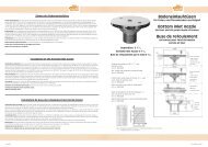
2. INSTALLATION<br />
Die Anlage wird serienmässig mit allen erforderlichen<br />
Anschlusselementen geliefert. Der Einbausatz<br />
ist passend für eine 240 mm/250 mm,<br />
alternativ 150 mm starke Betonwand ausgelegt.<br />
Er sollte so eingebaut werden, dass die Mitte der<br />
Strahldüse ca. 200 - 250 mm unter dem Wasserspiegel<br />
liegt und einen Mindestabstand zur<br />
seitlichen Wand von 1,5 m hat.<br />
Nach Fertigstellung der Bauarbeiten und säubern<br />
der Einbausätze von event. Mörtel wird die<br />
Armatur montiert. Falls ein Haltegriff zum Lieferumfang<br />
gehört, muss dieser vorher montiert<br />
werden. Der PN- und Luftanschluss der Armatur<br />
sind mit den entsprechenden Übergängen im<br />
Einbausatz zu verbinden. Beim Einschieben der<br />
Armatur dürfen die Schläuche nicht geknickt<br />
werden. Die Armatur mittels der mitgelieferten<br />
Schrauben am Einbausatz befestigen.<br />
Im Pumpenschacht wird anschliessend an dem<br />
Luftschlauch das Rückschlagventil angebracht.<br />
Das Rückschlagventil sollte über dem Wasserspiegel<br />
befestigt werden. PN-Schlauch über den<br />
Wasserspiegel legen und an der Schaltung anschliessen.<br />
Die Verbindung zwischen Pumpe und<br />
Einbausatz wird nach Zeichnung und Stückliste<br />
gemacht.<br />
3. INBETRIEBNAHME<br />
Anlage nur bei gefülltem Becken in Betrieb<br />
nehmen. Ein Trockenlaufen der Pumpe ist unbedingt<br />
zu vermeiden.<br />
1. Beide Schieber (falls vorhanden) öffnen und<br />
Anlage pneumatisch einschalten.<br />
2. Luftbeimischung überprüfen.<br />
3. Mengenverstellung überprüfen.<br />
4. Schlauchverbindungen im Betriebszustand<br />
überprüfen. Durch Temperaturunterschiede<br />
kann ein Nachziehen der Schlauchschellen<br />
erforderlich werden. (Armatur soweit wie<br />
möglich drosseln und auf Dichtigkeit überprüfen).<br />
4. BEDIENUNG<br />
Die Armatur der Gegenschwimmanlage beinhaltet<br />
alle Bedienungselemente. Über den Pneumatikschalter<br />
wird die Anlage durch Fingerdruck<br />
ein- und ausgeschaltet. Der Luftregler ermög-<br />
Installation instructions.<br />
<strong>FITSTAR</strong> Counter-current equipment<br />
1. LOCATION<br />
Place the pump of the counter-current-system as<br />
close to the pool as possible. Install the pump<br />
with the shaft in a horizontal position. If, for constructional<br />
reasons, it is not possible to place the<br />
pump in the ideal position, it should be located<br />
not more than 5 metres away, to prevent excessive<br />
flow reduction on the suction side. Pipes<br />
must be laid horizontally, with no sharp bends.<br />
If the distance of the pump from the pool has<br />
to exceed 5 metres, the pipe diameter must be<br />
increased accordingly. Select a location for the<br />
pump where the ambient temperature does not<br />
exceed 40° C. Ensure that the pump and valves<br />
are readily available. Provison of ventilation and<br />
drainage in the pump well is mandatory.<br />
2. MECHANICAL INSTALLATION<br />
The equipments is supplied as standard with all<br />
necessary fittings. The wall pack is suitable for<br />
240 / 250 mm, alternative 150 mm thick concrete<br />
wall, and is mounted to that the centre of<br />
the jet nozzle is between 200 and 250 mm below<br />
water lavel and is not less than 1,5 metres from<br />
the nearest side wall.<br />
Make the connections after construction work is<br />
finished and all traces of concrete have been removed<br />
from the surfaces of the wall pack. If using<br />
handle it must be mounted now. The pneumatics<br />
and air connection of the fitting must be<br />
connected with the transitions in the wall pack.<br />
When pushing in the fitting the hoses may not<br />
broken. Fix the fitting by using the delivered<br />
screws on the wall pack.<br />
Now the non-return-valve must be connected<br />
to the air hose. The non-return-valve must be<br />
installed above water level. The pneumatic hose,<br />
installed above the water level, is connected to<br />
the control box.<br />
Complete the piping between the pump and the<br />
wall pack in accordance with the installion diagram<br />
and parts list.<br />
3. COMMISSIONING<br />
Ensure that the pool is full of water. The pump<br />
must not run dry.<br />
1. Open both valves and turn on the pneumatic<br />
installation.<br />
2. Check air injection.<br />
3. Check the quantity-regulation.<br />
4. Hose couplings have to be checked during<br />
working process. Because of temperature difference<br />
it can appear that the hose band clip<br />
must be tightened. (Check the system for<br />
leaks by throttling down the controls as far<br />
as possible).<br />
4. OPERATION<br />
The unit includes all the necessary controls. It is<br />
switched on and off by pressing the pneumatic<br />
switch button. Air is injected into the jet by turning-up<br />
the air regulator. The speed of the current<br />
is adjusted by means of the quantity-egulation.<br />
The nozzle can be swivelled. Adjust the current<br />
speed so that the swimmer can swim against the<br />
full jet.<br />
5. OVERWINTER<br />
With outdoor pool, we recommend that the<br />
gate valves are shut, and the pump is drained,<br />
disconnected from the system and stored in a<br />
frost-free environment. If this is not possible, it<br />
is mandatory to drain the pump by closing both<br />
gate valves and opening fully the drain screw on<br />
the pump housing.<br />
Mise en place et Mode d’emploi<br />
Nage à contre courant <strong>FITSTAR</strong><br />
1. EMPLACEMENT<br />
Il est conseillé de placer le groupe électropompe<br />
de nage à contre courant de façon à ce que le<br />
raccordement entre la pompe et la pièce à sceller<br />
et de commande soit aussi réduit que possible.<br />
Veiller à ce que le groupe électropompe soit<br />
horizontal. Celui ci peut être déplacé mais, afin<br />
d‘éviter des pertes de charge importantes dans<br />
le conduit d‘aspiration, il est conseillé de ne pas<br />
dépasser une distance de 5 m. Il est indispensable<br />
de placer la pompe dans un endroit où la<br />
température ambiante ne dépasse pas 40°C. Le<br />
groupe électro-pompe n‘étant pas automorcant,<br />
doit être installé en-dessous du niveau d‘eau. La<br />
pompe et les vannes d‘arrêt doivent être facilement<br />
accessibles. Dans le puit de pompe (ou<br />
local technique enterré), il est absolument indispensable<br />
de prévoir un système de ventilation et<br />
un drainage (écoulement).<br />
2. MONTAGE<br />
La livraison comprend de série tous les éléments<br />
de montage nécessaires. Ces éléments sont prévus<br />
pour un mur de béton de 240/250 mm (avec<br />
une alternative 150 mm d‘épaisseur). L‘axe du<br />
jet doit se trouver entre 200/250 mm en-dessous<br />
du niveau de l‘et et 1,5 m d‘un mur opposé.<br />
Après achèvement des travaux de construction,<br />
un nettoyage éventuelle des éléments est à effecteur.<br />
Montage de la plaque de commande. Dans le cas<br />
où une poignée fait partie de la livraison, celleci<br />
doit être montée préalablement (voir optionacessoires).<br />
Les tuyaux de commande pneumatique<br />
et d‘air sont à introduire dans les tubes de<br />
raccordement faisant partie de la pièce à sceller.<br />
La mise en place de la plaque de commande ce<br />
fait à l‘aide de vis fraisées sur la pièce à sceller.<br />
Ne pas plier, ni coincer le tube de commande<br />
pneumatiqe.<br />
Dans le puit de pompe fixer le tuyau d‘air sur<br />
le clapet anti-retour, ce dernier doit être installé<br />
au-dessus du niveau de l‘eau. Le tuyau de commande<br />
pneumatique, qui doit être installé audessus<br />
du niveau de l‘eau, est à raccorder au<br />
boîtier de commande électro-pneumatique. Les<br />
raccordements et le montage sont à effectuer<br />
suivant la vue éclatée et fonction des pièces<br />
fournies.<br />
3. MISE EN SERVICE<br />
Ne mettre en service l‘installation que lorsque le<br />
bassin est plein d‘eau. Une mise en marche de la<br />
pompe à sec est absolument à éviter.<br />
1. Ouvrir les deux vannes (si présentes) et<br />
actionner la commande pneumatique.<br />
2. Contrôler l‘addition d‘air.<br />
3. Contrôler la réduction de débit.<br />
4. Contrôler les raccord de tuyaux en état de<br />
marche, par différence de température. Il<br />
est possible qu‘un serrage des colliers soit<br />
nécessaire (reduire le débit pour contrôler<br />
l'étanchéité).<br />
4. EMPLOI<br />
La plaque côté bassin de la nage à contrecourant<br />
comprend tous les éléments de commande.<br />
L‘arrêt et la mise en marche de l‘appareil<br />
s‘effectue par la pression d‘un doigt, sur<br />
l‘interrupteur pneumatique. Le régulateur d‘air<br />
rend possible une addition d‘air au jet d‘eau. Par<br />
réglage du débit d‘eau, la puissance du jet d‘eau<br />
peut être modulée et la buse peu être orientée<br />
dans toutes les directions. La direction du jet doit<br />
être directement sur le nageur.<br />
Stand 12/2006 Art. Nr.: 576229<br />
12