Einbauanleitung für FITSTAR Gegenschwimmanlagen
Einbauanleitung für FITSTAR Gegenschwimmanlagen
Einbauanleitung für FITSTAR Gegenschwimmanlagen

Create successful ePaper yourself
Turn your PDF publications into a flip-book with our unique Google optimized e-Paper software.
Eine Marke der<br />
Hugo Lahme GmbH<br />
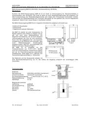
Elektrischer Anschluss (bauseits zu erstellen)<br />
Für die Drehstrom-Pumpe wird ein Zuleitungskabel von 5 x 2,5 mm² benötigt. Das Zuleitungskabel vom PN-Schaltkasten<br />
zur Pumpe ist 4 x 2,5 mm². Absicherung für 16 Ampere träge. Fehlerstom FI-Schalter, der für die Gegenschwimmanlage<br />
bestimmt ist (FI-Schutzorgan Nennfehlerstrom-30mA) muss in jedem Fall installiert werden.<br />
Einbau einer PN-Schaltung.<br />
Die maximale Entfernung der PN-Schaltung vom Schalter beträgt 25 m. Es ist darauf zu achten, dass der PN-Schlauch<br />
knickfrei, unbedingt oberhalb des Wasserspiegels verlegt werden muss. Der pneumatische Schaltkasten ist in einem trockenen<br />
Raum zu installieren.<br />
ACHTUNG: PN-Schlauch muss eine Mindestlänge von 5 m haben. Der Schlauch darf nicht unter 5 m gekürzt werden!<br />
Zur Sicherung der Pumpe ist ein Motorschutzschalter in die Pneumatikschaltung eingebaut. Dieser Motorschutz muss<br />
bauseitig eingestellt werden. Es ist vom Elektriker erforderlich, die Stromaufnahme der Phasen im Betriebszustand zu<br />
messen und auf den gemessenen Nennstrom einzustellen, eine Überprüfung der Funktion ist unbedingt erforderlich. Die<br />
Luftdruckempfindlichkeit der Pneumatikschaltung muss eingestellt werden (Regulierschraube am Druckwellenschalter).<br />
Eindrehen: Schaltung wird empfindlicher. Herausdrehen: Schaltung wird unempfindlicher.<br />
ACHTUNG: Sämtliche Bronze-Einbauteile sind an einem Potentialausgleich (Potentialringleitung) anzuklemmen. Die<br />
Vorschriften des VDE und des örtlichen EVU (Elektrizitäts-Versorgungs-Unternehmen) sind bei der Installation der Anlage<br />
unbedingt zu beachten. Installation nur durch einen beim örtlichen EVU zugelassenen Elektro-Installateur ausführen lassen<br />
nach VDE 0100 Teil 702 und 430.<br />
Electrical Installation<br />
For the threephase pump it is necessary to install an electric cable 5 x 2,5 mm². The electric cable from the PN-Switch box<br />
to the pump is 4 x 2,5 mm². They also require a suitably sized supply cable with 16 A fuse protection. The equipment must<br />
be protected by a 30 mA residal current device mounted away from the pool.<br />
PN-circuit installation.<br />
The maximum distance from the PN circuit to the switch is 25 meters as standard.If required, modifications can be made to<br />
extend this distance; please consult your distributor. It is important to install the PN-hose with no sharp bends and above<br />
the water level. The pneumatic switchbox must be installed in a dry place.<br />
ATTENTION: PN-hose must be minimum 5 m. It is not allowed to make it shorter than 5 m!<br />
A motor protection switch is provided in the pneumatic circuit for the pumps. The electrician has to measure the consume<br />
current of the phases in working order and has to adjust it on the measured nominal current. The switch must be adjusted<br />
before use and its satisfactory operation checked. Adjust the sensitivity of the PN circuit for air pressure-screw the adjuster<br />
in for greater sensitivity, out for lesser sensitivity.<br />
ATTENTION: All bronze mounting parts must be cross-bonded and earthed in a approved manner. Electrical installation<br />
must be carried out by a qualified electrician and in accordance with IEE and local regulation current at the time.<br />
Raccordement électrique<br />
Il est nécessaire, pour l‘alimentation de la pompe de prévoire un câble de 5 x 2,5². Le câble de liaison de la commande<br />
électro-pneumatique a la pompe est à prévoir de 4 x 2,5². Une protection par fusibles 16 A (AM) et une protection differentielle<br />
calibré à 30 mA doit être installer.<br />
Installation de la commande électro-pneumatique.<br />
La distance maximum entre le bouton de commande et le coffret électro-pneumatique ne doit par dépasser 25 m. Il est<br />
important d‘installer le tube de commande pneumatique au-dessus du niveau d‘ eau et sans le plier. Le coffret de commande<br />
électro-pneumatique est à installer dans un local sec.<br />
ATTENTION: Le tube de commande pneumatique ne doit pas avoir une longueur inférieur à 5 m. On ne lui permet pas<br />
de lui faire plus sous peu que 5 mètres!<br />
Une protection thermique de pompe est prévue dans la boîtier elctro-pneumatiqe (IP 65) celle ci est à tégler par l‘installateur<br />
en function des données de plaque signalitique de moteur. Un contrôl de la commande pneumatique est egalement conseiller<br />
un réglage de sensibilité est prevue (vis cruciforme sur l‘interrupteur pneumatique).<br />
Visser: Augmentation de sensibilité. Dévisser: Diminution de sensibilité.<br />
ATTENTION: Toutes les piéces en bronze doivent être relier au circuit équipotentiel conforme aux prescriptions de la<br />
C 1500 EDF lors du montage. Le montage doit être exécuté par un électricien agée.<br />
Stand 12/2006 Art. Nr.: 576229<br />
11