Einbauanleitung für FITSTAR Gegenschwimmanlagen
Einbauanleitung für FITSTAR Gegenschwimmanlagen
Einbauanleitung für FITSTAR Gegenschwimmanlagen

You also want an ePaper? Increase the reach of your titles
YUMPU automatically turns print PDFs into web optimized ePapers that Google loves.
Eine Marke der<br />
Hugo Lahme GmbH<br />
Eine Marke der<br />
Hugo Lahme GmbH<br />
<strong>Einbauanleitung</strong> für<br />
<strong>FITSTAR</strong> <strong>Gegenschwimmanlagen</strong><br />
Instructions <strong>FITSTAR</strong> counter-current-systems<br />
L'installation pour nage à contre-courant de <strong>FITSTAR</strong><br />
Anschlussarmaturen Seite 3-4<br />
Connecting fittings<br />
Élément de jonctions<br />
Anschlusssatz Taifun, Taifun Duo und Tornado Seite 5<br />
Fittings Taifun, Taifun Duo and Tornado<br />
Kit de raccordement Taifun, Taifun Duo et Tornado<br />
Anschlusssatz Junior und Uni Seite 6<br />
Fittings Junior and Uni<br />
Kit de raccordement Junior et Uni<br />
Anschlusssatz Taifun-kompakt und Junior-kompakt Seite 7<br />
Fittings Taifun-kompakt and Junior-kompakt<br />
Kit de raccordement Taifun-kompakt et Junior-kompakt<br />
Zusatzteile Seite 8 - 9<br />
Accessories<br />
Accessoires<br />
Stand 12/2006<br />
Anschluss PN-Schaltung Seite 10 - 11<br />
PN-circuit installation<br />
Installation de commando electro-pneumatique<br />
Einbau- und Bedienungsanleitung Seite 12 - 13<br />
Installation instructions<br />
Mise en place et mode d‘emploi<br />
1<br />
Art. Nr.: 576229
Eine Marke der<br />
Hugo Lahme GmbH<br />
Anschlusssatz<br />
Fittings<br />
Ensemble de raccordement<br />
Anschlusssatz<br />
Bestehend aus Anschlussarmatur mit haaransaugsicherer Blende aus Edelstahl A4, Pneumatikschalter<br />
sowie Luftregulier- und Mengenverstellhebel. Die Einstrahldüse ist richtungsverstellbar. Die Armatur<br />
hat einen stufenlosen Putzausgleich bis 35 mm. Pumpe aus Rotguss, Pneumatikschaltung Schutzart<br />
IP 65, 5 m Pneumatikschlauch.<br />
Fittings<br />
Comprising: connectors with cover out of stainless steel V4A protected against suction of hair, pneumatic<br />
circuit as well as air regulating- and rate control lever. Gate valve; bronze countercurrent pump;<br />
pneumatic circuit protection class IP 65 with 5m pneumatic hose. The nozzle can be swivelled in all<br />
directions. The depth of the fittings in the rending can be varied by up to 35 mm.<br />
Kit de raccordement<br />
Celui ci comprend tous les éléments de raccordements et crépine de l‘aspiration sécurité cheveux. Les<br />
buses sont multidirectionnelles, tous les éléments côté bassin sont réglables jusqu‘a une épaisseur de<br />
mortier et carrelage de 35 mm. La pompe en bronze avec sa commande electropneumatique degré<br />
de protection IP 65 et de son tuyau d‘une longueur de 5 m.<br />
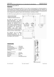
ACHTUNG:<br />
Bei Wasserattraktionen kann während längerer Stillstandzeiten das stagnierende Wasser im Rohrsystem<br />
verkeimen und dadurch das Beckenwasser hygienisch belasten. Um dieser Verkeimungsgefahr<br />
entgegenzuwirken und die hygienische Anforderung der DIN zu erfüllen, wird empfohlen,<br />
einen Teilstrom des Reinwassers über einen geregelten Bypass zur Zwangsdurchströmung in das<br />
Rohrsystem der Wasserattraktionen zu führen. Eine weitere Möglichkeit zur Einhaltung der erforderlichen<br />
Grenzwerte ist ebenfalls über eine Zwanglaufschaltung gegeben.<br />
ATTENTION:<br />
With water attractions the stagnation water in the tubing system can germinate and load thus the<br />
basin water unhygienic during longer downtimes. In order to counteract germinating danger and<br />
to fulfil the hygienic request of the DIN standard, it is recommended to lead a part of the pure<br />
water flow over a regulated bypass. This is done for the purpose of creating a forced current into<br />
the tubing system of the water attraction. A further possibility to keep the necessary limit values is<br />
likewise given with a controlled movement circuit.<br />
ATTENTION:<br />
Avec les attractions aquatique, la possibilité de contamination d‘eau stagnante dans les tuyauteries<br />
lors d‘un arrêt prolonger, peu provoquer une contamination bacteriel residuel dans le volume du<br />
bassin lors de la remise en service. Afin de remedier a cet effet et de respecter les normes d‘hygiène,<br />
nous recommandons d‘installer sur le circuit primaire une vanne de derivation pouvant servir de<br />
purge vers circuit eau usée, ou d‘installer une commande periodique de mise en marche.<br />
Stand 12/2006 Art. Nr.: 576229<br />
2
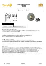
Anschlussarmaturen<br />
Connecting fittings<br />
Élément de jonctions<br />
Eine Marke der<br />
Hugo Lahme GmbH<br />
GSA - TAIFUN DUO<br />
GSA - TAIFUN<br />
(rund / round / ronde)<br />
GSA - TAIFUN<br />
(rechteckig / rectangular /<br />
carré)<br />
GSA - JUNIOR GSA -<br />
TORNADO<br />
Stand 12/2006 Art. Nr.: 576229<br />
3
Eine Marke der<br />
Hugo Lahme GmbH<br />
Anschlussarmaturen<br />
Connecting fittings<br />
Élément de jonctions<br />
GSA - TAIFUN DUO<br />
GSA - TAIFUN (rund / round / ronde)<br />
GSA - TAIFUN<br />
(rechteckig /<br />
rectangular / carré)<br />
GSA - JUNIOR GSA -<br />
TORNADO<br />
Stand 12/2006 Art. Nr.: 576229<br />
4
Eine Marke der<br />
Hugo Lahme GmbH<br />
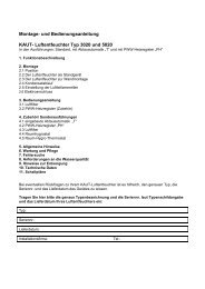
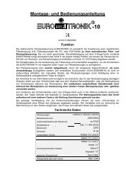
Anschlusssatz Typ TAIFUN, TAIFUN DUO und TORNADO<br />
Fittings type TAIFUN, TAIFUN DUO and TORNADO<br />
Kit de raccordement type TAIFUN, TAIFUN DUO et TORNADO<br />
ACHTUNG!<br />
PN-Schlauch und<br />
Rückschlagventil über<br />
den Wasserspiegel legen.<br />
ATTENTION!<br />
PN-hose and the<br />
non-return-valve must<br />
be installed above the<br />
water level.<br />
ATTENTION!<br />
Le tuyau de commande<br />
pneumatique et le clapet<br />
de retenue doivent être<br />
installé au dessus du<br />
niveau d‘eau.<br />
Pumpenschacht<br />
Mindestmaße L = 80 cm, B = 50 cm<br />
Höhe unter dem Wasserspiegel = 75 cm<br />
Es ist unbedingt eine Be- und Entlüftung, sowie<br />
eine Entwässerung vorzusehen.<br />
Pos. Stck. Bezeichnung Art.-Nr.<br />
1a 1 Anschlussarmatur 7307020<br />
TAIFUN rund kpl.<br />
1b 1 Anschlussarmatur 7308020<br />
TAIFUN rechteckig kpl.<br />
1c 1 Anschlussarmatur 7309920<br />
TAIFUN DUO kpl.<br />
1d 1 Anschlussarmatur 7305000<br />
TORNADO kpl.<br />
2a 1 Einbausatz 7610050<br />
TAIFUN 240 mm kpl.<br />
2b 1 Einbausatz 7613050<br />
TAIFUN DUO 240 mm kpl.<br />
2c 1 Einbausatz 8100050<br />
TORNADO 240 mm kpl.<br />
3 2 Verbindungselement mit 7182550<br />
Überwurfmutter G 2½<br />
4 2 Schieber G 2½ 7183050<br />
mit Einschraubventil<br />
5 2 Schlauchtülle 7070050<br />
NW 65, G 2½ AG<br />
6 2 Hochdruckschlauch 575395<br />
NW 65, 100 mm lang<br />
7 4 Schlauchschelle NW 76 575678<br />
8 2 Schlauchtülle kpl. mit 7162050<br />
Überwurfmutter G 2½<br />
und Dichtung<br />
9 1 Pumpendruckstutzen 7158550<br />
G 2½ mit Dichtung u.<br />
Schrauben<br />
10 1 RG-Pumpe 2,6 kW DS, 7754050<br />
mit Saugstutzen G 2½<br />
normals.<br />
11 1 PN-Schaltung 7322160<br />
Pump shaft<br />
Minimum L = 80 cm, B = 50 cm<br />
Height below water-level = 75 cm<br />
It is absolutely essential to provide ventilation as<br />
well as drainage in the pump shaft.<br />
Item Quan. Description<br />
Art.-Nr.<br />
1a 1 connection fitting 7307020<br />
round TAIFUN compl.<br />
1b 1 connection fitting 7308020<br />
rectangular TAIFUN<br />
compl.<br />
1c 1 connection fitting 7309920<br />
TAIFUN DUO compl.<br />
1d 1 connection fitting 7305000<br />
TORNADO compl.<br />
2a 1 wall-pack TAIFUN 7610050<br />
240 mm compl.<br />
2b 1 wall-pack TAIFUN DUO 7613050<br />
240 mm compl.<br />
2c 1 wall-pack TORNADO 8100050<br />
240 mm compl.<br />
3 2 joining element G 2½ 7182550<br />
4 2 gate valve G 2½ 7183050<br />
5 2 hose nozzle 7070050<br />
NW 65,G 2½<br />
6 2 high pressure hose 575395<br />
NW 65, 100 mm long<br />
7 4 hose clip NW 76 575678<br />
8 2 cap srew G 2½ 7162050<br />
with hose nozzle NW 65<br />
and gasket<br />
9 1 pump elbow G 2½ 7158550<br />
with gasket and screws<br />
10 1 bronze pump 7754050<br />
2,6 kW DS, with flange<br />
connection G 2½<br />
11 1 pneumatic-switch 7322160<br />
connection<br />
Caisson de pompe<br />
Minimum L = 80 cm, B = 50 cm<br />
Hauteur au dessous du niveau d'eau = 75 cm<br />
Il faut absolument prèvoir une ventilation et aération<br />
ainsi qu'un drainage dans le caisson de pompe.<br />
Item Quan Description<br />
Art.-No.<br />
1a 1 plague ronde de 7307020<br />
commande TAIFUN<br />
compl.<br />
1b 1 plaque rectangulaire de 7308020<br />
commande TAIFUN<br />
compl.<br />
1c 1 plaque de commande 7309920<br />
TAIFUN DUO compl.<br />
1d 1 plaque de commande 7305000<br />
TORNADO compl.<br />
2a 1 pièce à sceller TAIFUN 7610050<br />
240 mm<br />
2b 1 pièce à sceller 7613050<br />
TAIFUN DUO 240 mm<br />
2c 1 pièce à sceller 8100050<br />
TORNADO 240 mm<br />
3 2 raccord G 2½“ compl. 7182550<br />
4 2 vanne G 2½“ 7183050<br />
5 2 douille NW 65, G 2½“ 7070050<br />
6 2 tuyau à haute pression 575395<br />
NW 65, 100 mm<br />
7 4 collier de serrage NW 76 575678<br />
8 2 enbout NW 65 avec 7162050<br />
ecrou à rapport G 2½“<br />
avec joint<br />
9 1 coude de sortie G 2½“ 7158550<br />
avec joint et vis<br />
10 1 pompe en bronze 7754050<br />
2,6 kW DS avec raccord<br />
de bride G 2½“<br />
11 1 Boîtier de commande 7322160<br />
electro-pneumatique IP 65<br />
Stand 12/2006 Art. Nr.: 576229<br />
5
Eine Marke der<br />
Hugo Lahme GmbH<br />
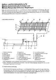
Anschlusssatz Typ JUNIOR und UNI<br />
Fittings type JUNIOR and UNI<br />
Kit de raccordement type JUNIOR et UNI<br />
ACHTUNG!<br />
PN-Schlauch und<br />
Rückschlagventil über<br />
den Wasserspiegel legen.<br />
ATTENTION!<br />
PN-hose and the<br />
non-return-valve must<br />
be installed above the<br />
water level.<br />
ATTENTION!<br />
Le tuyau de commande<br />
pneumatique et le clapet<br />
de retenue doivent être<br />
installé au dessus du<br />
niveau d‘eau.<br />
Pumpenschacht<br />
Mindestmaße L = 80 cm, B = 50 cm<br />
Höhe unter dem Wasserspiegel = 75 cm<br />
Es ist unbedingt eine Be- und Entlüftung, sowie<br />
eine Entwässerung vorzusehen.<br />
Pos. Stck. Bezeichnung Art.-Nr.<br />
1a 1 Anschlussarmatur 7304020<br />
JUNIOR kpl.<br />
1b 1 Anschlussarmatur 7303020<br />
UNI kpl.<br />
2a 1 Einbausatz JUNIOR 8000050<br />
240 mm kpl.<br />
2b 1 Einbausatz UNI 7910050<br />
240 mm kpl.<br />
3 2 Doppelnippel G2 IG, 7040050<br />
90 mm<br />
4 2 Schieber G 2 501901<br />
5 2 Schlauchtülle NW 50, 7060050<br />
G 2 AG<br />
6 2 Schlauch NW 50, 510560<br />
100 mm lang<br />
7 4 Schlauchschelle NW 64 500507<br />
8 2 Schlauchtülle kpl. mit 7062050<br />
Überwurfmutter G 2 und<br />
Dichtung aus Gummi<br />
9 1 Pumpendruckstutzen 7150050<br />
mit Dichtung u.Schrauben<br />
für 2,2 kW Pumpe 7751050<br />
und 1,5 kW Pumpe 7752050<br />
1 Pumpendruckstutzen 7158050<br />
für 2,6 kW Pumpe 7753050<br />
10 1 RG-Pumpe, normalsaugend<br />
m. Ansaugstutzen G 2 AG:<br />
2,2 kW, DS 7751050<br />
1,5 kW, WS 7752050<br />
2,6 kW, DS 7753050<br />
11 1 PN-Schaltung 2,2 kW 7322150<br />
PN-Schaltung 1,5 KW 7313050<br />
PN-Schaltung 2,6 kW 7322160<br />
Pump shaft<br />
Minimum L = 80 cm, B = 50 cm<br />
Height below water-level = 75 cm<br />
It is absolutely essential to provide ventilation as<br />
well as drainage in the pump shaft.<br />
Item Quan. Description<br />
Art.-Nr.<br />
1a 1 connection fittings 7304020<br />
JUNIOR compl.<br />
1b 1 connection fittings UNI 7303020<br />
compl.<br />
2a 1 wall-pack JUNIOR 8000050<br />
240 mm compl.<br />
2b 1 wall-pack UNI 7910050<br />
240 mm compl.<br />
3 2 double nipple 7040050<br />
G 2 x 90 mm<br />
4 2 gate valve G 2 501901<br />
5 2 hose nozzle NW 50, G 2 7060050<br />
6 2 hose NW 50, 510560<br />
100 mm long<br />
7 4 hose clip NW 64 500507<br />
8 2 cap screw G 2 with hose 7062050<br />
nozzle NW 50 and rubber<br />
9 1 pump elbow G 2 compl. 7150050<br />
with gasket and screws<br />
for 2,2 kW pump 7751050<br />
and 1,5 kW pump 7752050<br />
1 pump elbow for 7158050<br />
pump 7753050<br />
10 1 bronze pump with standard<br />
G 2 suction and outlet<br />
connection:<br />
2,2 kW, 3 phase 7751050<br />
1,5 kW, 1 phase 7752050<br />
2,6 kW, 3 phase 7753050<br />
11 1 pneumatic-switch<br />
connection:<br />
2,2 kW 7322150<br />
1,5 kW 7313050<br />
2,6 kW 7322160<br />
Caisson de pompe<br />
Minimum L = 80 cm, B = 50 cm<br />
Hauteur au dessous du niveau d'eau = 75 cm<br />
Il faut absolument prèvoir une ventilation et aération<br />
ainsi qu'un drainage dans le caisson de pompe.<br />
Item Quan. Description<br />
Art.-No.<br />
1a 1 plague de commande 7304020<br />
JUNIOR compl.<br />
1b 1 plaque de commande 7303020<br />
UNI compl.<br />
2a 1 pièce à sceller JUNIOR 8000050<br />
240 mm compl.<br />
2b 1 pièce à sceller UNI 7910050<br />
240 mm compl.<br />
3 2 mamelon G 2“ x 90 mm 7040050<br />
4 2 vanne G 2“ 501901<br />
5 2 raccord G 2“ cannelé 7060050<br />
NW 50<br />
6 2 tuyau haute pression 510560<br />
NW 50, 100 mm<br />
7 4 collier de serrage NW 64 500507<br />
8 2 enbout NW 50 avec 7062050<br />
écrou à rapport G 2“<br />
avec joint<br />
9 1 coude de sortie G 2“ 7150050<br />
compl. avec joint et vis<br />
pour 2,2 kW pompe 7751050<br />
et 1,5 kW pompe 7752050<br />
1 coude de sortie pour 7158050<br />
2,6 kW pompe 7753050<br />
10 1 pompe en bronze avec<br />
aspiration G 2“:<br />
2,2 kW, TRI 7751050<br />
1,5 kW, MONO 7752050<br />
2,6 kW, TRI 7753050<br />
11 1 Boîtier de commande 7322150<br />
electro-pneumatique<br />
2,2 kW IP 65<br />
Boîtier de commande 7313050<br />
1,5 kW IP 65<br />
Boîtier de commande 7322160<br />
2,6 kW IP 65<br />
Stand 12/2006 Art. Nr.: 576229<br />
6
Eine Marke der<br />
Hugo Lahme GmbH<br />
Anschlusssatz Typ TAIFUN - kompakt<br />
Fittings type Type TAIFUN - Compakt<br />
Kit de raccordement type TAIFUN - Kompakt<br />
Pos. Stck. Bezeichnung<br />
Art.-Nr.<br />
1a 1 Anschlussarmatur rund kpl. 7307020<br />
1b 1 Anschlussarmatur eckig kpl. 7308020<br />
2a 1 Einbausatz 250 mm kpl. 7611050<br />
2b 1 Einbausatz 130 mm kpl. 7611850<br />
3 1 RG-Pumpe 2,6 kW DS, 7754250<br />
mit Flanschanschlüssen<br />
4 1 PN-Schaltung 7322160<br />
Item Quan. Description<br />
Art.-Nr.<br />
1a 1 connection fitting 7307020<br />
round compl.<br />
1b 1 connection fitting 7308020<br />
rectangular compl.<br />
2a 1 wall-pack 250 mm compl. 7611050<br />
2b 1 wall-pack 130 mm compl. 7611850<br />
3 1 bronze pump 2,6 kW DS, 7754250<br />
with flanges<br />
4 1 pneumatic-switch 7322160<br />
connection<br />
ACHTUNG!<br />
PN-Schlauch und Rückschlagventil über<br />
den Wasserspiegel legen.<br />
Pumpe (Pos. 3) darf nur in Verbindung mit<br />
einem Sockel oder einer Pumpenkonsole<br />
(Art.-Nr. 7280050) montiert werden.<br />
ATTENTION!<br />
PN-hose and the non-return-valve<br />
must be installed above the water level.<br />
Pump (position 3) must be installed only in<br />
connection with a base or a pump console<br />
(Art.-No. 7280050)<br />
ATTENTION!<br />
Le tyau de commande pneumatique et le<br />
clapet de retenue doivent être installé au<br />
dessus du niveau d‘eau.<br />
Pompe (la position 3) doit être installé<br />
sulement en liaison avec une base ou une<br />
console de pompe (Art.-No. 7280050).<br />
Item Quan. Description<br />
Art.-No.<br />
1a 1 plague ronde de 7307020<br />
commande compl.<br />
1b 1 plaque rectangulaire de 7308020<br />
commande compl.<br />
2a 1 pièce à sceller 250 mm compl. 7611050<br />
2b 1 pièce à sceller 130 mm compl. 7611850<br />
3 1 pompe en bronze 2,6 kW DS, 7754250<br />
avec raccordement à bride<br />
4 1 Boîtier de commande 7322160<br />
electro-pneumatique<br />
Typ JUNIOR - kompakt<br />
Type JUNIOR - Compakt<br />
Type JUNIOR - Kompakt<br />
ACHTUNG!<br />
PN-Schlauch und Rückschlagventil über<br />
den Wasserspiegel legen.<br />
ATTENTION!<br />
PN-hose and the non-return-valve must<br />
be installed above the water level.<br />
ATTENTION!<br />
Le tuyau de commande pneumatique et<br />
le clapet de retenue doivent être installé<br />
au dessus du niveau d‘eau.<br />
Pos. Stck. Bezeichnung<br />
Art.-Nr. Item Quan. Description<br />
Art.-Nr. Item Quan. Description<br />
Art.-No.<br />
1 1 Anschlussarmatur kpl. 7304020 1 1 connection fitting compl. 7304020 1 1 plague de commande compl. 7304020<br />
2 1 Einbausatz 250 mm kpl. 8011050 2 1 wall-pack 250 mm compl. 8011050 2 1 pièce à sceller 250 mm compl. 8011050<br />
3 1 RG-Pumpe 2,2 kW DS mit 7751150 3 1 bronze pump 2,2 kW DS, 7751150 3 1 pompe en bronze 7751150<br />
Flansch, normalsaugend<br />
with flange<br />
2,2 kW DS, avec bride<br />
4 1 PN-Schaltung 7322150 4 1 pneumatic-switch 7322150 4 1 Boîtier de commande 7322150<br />
connection<br />
electro-pneumatic<br />
Pumpenschacht<br />
Pump shaft<br />
Caisson de pompe<br />
Mindestmaße L = 80 cm, B = 50 cm<br />
Minimum L = 80 cm, B = 50 cm<br />
Minimum L = 80 cm, B = 50 cm<br />
Höhe unter dem Wasserspiegel = 75 cm<br />
Height below water-level = 75 cm<br />
Hauteur au dessous du niveau d'eau = 75 cm<br />
Es ist unbedingt eine Be- und Entlüftung, sowie It is absolutely essential to provide ventilation as Il faut absolument prèvoir une ventilation et aération<br />
eine Entwässerung vorzusehen.<br />
well as drainage in the pump shaft.<br />
ainsi qu'un drainage dans le caisson de pompe.<br />
Stand 12/2006 Art. Nr.: 576229<br />
7
Eine Marke der<br />
Hugo Lahme GmbH<br />
Zusatzteile / Accessories / Accessoires<br />
Zusatzteile gehören nicht zum Lieferumfang und sind gesondert anzufordern.<br />
Accessories are not part of the standard unit and must be ordered separately.<br />
Les accessoires doivent faire l‘objet d‘une commande séparée.<br />
Pos. Bezeichnung<br />
Art.-Nr.<br />
1 Haltegriff rund,TAIFUN rund/ 7991020<br />
TAIFUN DUO/ UNI<br />
2 Haltegriff rechteckig, 8090020<br />
TAIFUN rechteckig/ JUNIOR<br />
3 Haltegriff rechteckig,TORNADO 8120020<br />
4 Pumpenkonsole 7280050<br />
5 Schiebersatz G 2½, 7190050<br />
TAIFUN-KOMPAKT<br />
6 Schiebersatz G 2, 8170050<br />
JUNIOR-KOMPAKT<br />
7 Massageschlauch, 7550050<br />
JUNIOR / JUNIOR-KOMPAKT<br />
8 Massageschlauch, TAIFUN / UNI 7551050<br />
9 Massageschlauch m. 8551050<br />
pulsierendem Wasserstrahl, TAIFUN<br />
10 Massageschlauch m. 7552050<br />
Verschlußstopfen, TAIFUN DUO<br />
11 Massageschlauch m. 8552050<br />
pulsierendem Wasserstrahl u.<br />
Verschlußstopfen,TAIFUN DUO<br />
12 Flanschringsatz, Folienbecken 7980050<br />
TAIFUN<br />
13 Flanschringsatz, Folienbecken 8080050<br />
JUNIOR / JUNIOR-KOMPAKT<br />
14 Flanschringsatz, Folienbecken 8130050<br />
TORNADO<br />
Item Description<br />
Art.-No.<br />
1 handle circle, TAIFUN round/ 7991020<br />
TAIFUN DUO / UNI<br />
2 handle rectangular, 8090020<br />
TAIFUN rectangular/ JUNIOR<br />
3 handle rectangular TORNADO 8120020<br />
4 pump bracket 7280050<br />
5 gate valve G 2½, 7190050<br />
TAIFUN-KOMPAKT<br />
6 gate valve G 2, 8170050<br />
JUNIOR-KOMPAKT<br />
7 massage hose, 7550050<br />
JUNIOR / JUNIOR-KOMPAKT<br />
8 massage hose, TAIFUN / UNI 7751050<br />
9 massage hose with pulsating 8551050<br />
water jet, TAIFUN<br />
10 massage hose with 1 drain 7552050<br />
plug TAIFUN DUO<br />
11 massage hose with pulsating 8552050<br />
water jet and 1 drain plug,<br />
TAIFUN DUO<br />
12 flange kit for liner pools, 7980050<br />
TAIFUN<br />
13 flange kit for liner pools, 8080050<br />
JUNIOR / JUNIOR-KOMPAKT<br />
14 flange kit for liner pools, 8130050<br />
TORNADO<br />
Item Description<br />
Art.-No.<br />
1 poignée simple ronde, 7991020<br />
TAIFUN ronde/ Taifun DUO/UNI<br />
2 poignée double rectangulaire, 8090020<br />
TAIFUN rectangulaire/ JUNIOR<br />
3 poignée simple rectangulaire 8120020<br />
TORNADO<br />
4 console de fixation 7280050<br />
5 vanne G 2½“, 7190050<br />
TAIFUN-KOMPAKT<br />
6 vanne G 2“, JUNIOR-KOMPAKT 8170050<br />
7 tuyau de massage, 7550050<br />
JUNIOR / JUNIOR-KOMPAKT<br />
8 tuyau de massage,TAIFUN / UNI 7551050<br />
9 tuyau de massage avec jet 8551050<br />
d‘eau pulsant, TAIFUN<br />
10 tuyau de massage 1 bouchon 7552050<br />
de fermeture, TAIFUN DUO<br />
11 tuyau de massage avec jet 8552050<br />
d‘eau pulsant et 1 bouchon de<br />
fermetere, TAIFUN DUO<br />
12 brides pour bassin avec liner, 7980050<br />
TAIFUN<br />
13 brides pour bassin avec liner, 8080050<br />
JUNIOR / JUNIOR-KOMPAKT<br />
14 brides pour bassin avec liner, 8130050<br />
TORNADO<br />
TAIFUN<br />
TAIFUN DUO<br />
TORNADO<br />
TAIFUN<br />
JUNIOR<br />
Technische Änderungen vorbehalten.<br />
The manufacturer reserves the right to<br />
change specification without notice.<br />
Nous nous réservons le droit de modifier<br />
les dimensions et les constructions.<br />
Stand 12/2006 Art. Nr.: 576229<br />
8
Eine Marke der<br />
Hugo Lahme GmbH<br />
Zusatzteile / Accessories / Accessoires<br />
Zusatzteile gehören nicht zum Lieferumfang und sind gesondert anzufordern.<br />
Accessories are not part of the standard unit and must be ordered separately.<br />
Les accessoires doivent faire l‘objet d‘une commande séparée.<br />
TAIFUN - kompakt<br />
TAIFUN<br />
JUNIOR<br />
JUNIOR-kompakt<br />
TORNADO<br />
Stand 12/2006 Art. Nr.: 576229<br />
9
Eine Marke der<br />
Hugo Lahme GmbH<br />
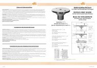
PN-Schaltung<br />
PN wiring<br />
Commande electro-pneumatique<br />
Schaltbild PN-Schaltung 400V / 3 ~ 2,2 kW DS<br />
mit Heizwiderstand<br />
Circuit diagram PN-wiring<br />
Schéma de raccordement<br />
Art.-Nr. 7322150<br />
R1 Heizwiderstand<br />
S1 D3-P<br />
X1 Anschlussklemmen<br />
X2 Anschlussklemmen<br />
K1 Schütz<br />
KO Stromstoßrelais<br />
E1 Motorschutz<br />
Schaltbild PN-Schaltung 400V / 3 ~ 2,6 kW DS<br />
mit Heizwiderstand<br />
Circuit diagram PN-wiring<br />
Schéma de raccordement<br />
Art.-Nr. 7322160<br />
R1 Heizwiderstand<br />
S1 D3-P<br />
X1 Anschlussklemmen<br />
X2 Anschlussklemmen<br />
K1 Schütz<br />
KO Stromstoßrelais<br />
E1 Motorschutz<br />
Achtung: Motorschutz einstellen<br />
Achtung: Motorschutz einstellen<br />
Schaltbild PN-Schaltung 1,5 + 2 kW / 230V~<br />
Circuit diagram PN-wiring<br />
Schéma de raccordement<br />
Art.-Nr. 7313050<br />
R1 Heizwiderstand<br />
S1 D3-P<br />
X1 Anschlussklemmen<br />
X2 Anschlussklemmen<br />
K1 Schütz<br />
KO Stromstoßrelais<br />
E1 Motorschutz<br />
An der Regulierschraube des Druckwellenschalters kann der<br />
Ansprechdruck eingestellt werden.<br />
The pick-up pressure can be adjusted by the adjusting screw<br />
at the pressure wave switch.<br />
Il est possible d‘ajuster la pression de commande avec la<br />
vis d‘ajustage de I‘interrupteur electro- pneumatique.<br />
Technische Änderungen vorbehalten.<br />
Achtung: Motorschutz einstellen<br />
The manufacturer reserves the right to<br />
change specification without notice.<br />
Nous nous réservons le droit de modifier<br />
les dimensions et les constructions.<br />
Stand 12/2006 Art. Nr.: 576229<br />
10
Eine Marke der<br />
Hugo Lahme GmbH<br />
Elektrischer Anschluss (bauseits zu erstellen)<br />
Für die Drehstrom-Pumpe wird ein Zuleitungskabel von 5 x 2,5 mm² benötigt. Das Zuleitungskabel vom PN-Schaltkasten<br />
zur Pumpe ist 4 x 2,5 mm². Absicherung für 16 Ampere träge. Fehlerstom FI-Schalter, der für die Gegenschwimmanlage<br />
bestimmt ist (FI-Schutzorgan Nennfehlerstrom-30mA) muss in jedem Fall installiert werden.<br />
Einbau einer PN-Schaltung.<br />
Die maximale Entfernung der PN-Schaltung vom Schalter beträgt 25 m. Es ist darauf zu achten, dass der PN-Schlauch<br />
knickfrei, unbedingt oberhalb des Wasserspiegels verlegt werden muss. Der pneumatische Schaltkasten ist in einem trockenen<br />
Raum zu installieren.<br />
ACHTUNG: PN-Schlauch muss eine Mindestlänge von 5 m haben. Der Schlauch darf nicht unter 5 m gekürzt werden!<br />
Zur Sicherung der Pumpe ist ein Motorschutzschalter in die Pneumatikschaltung eingebaut. Dieser Motorschutz muss<br />
bauseitig eingestellt werden. Es ist vom Elektriker erforderlich, die Stromaufnahme der Phasen im Betriebszustand zu<br />
messen und auf den gemessenen Nennstrom einzustellen, eine Überprüfung der Funktion ist unbedingt erforderlich. Die<br />
Luftdruckempfindlichkeit der Pneumatikschaltung muss eingestellt werden (Regulierschraube am Druckwellenschalter).<br />
Eindrehen: Schaltung wird empfindlicher. Herausdrehen: Schaltung wird unempfindlicher.<br />
ACHTUNG: Sämtliche Bronze-Einbauteile sind an einem Potentialausgleich (Potentialringleitung) anzuklemmen. Die<br />
Vorschriften des VDE und des örtlichen EVU (Elektrizitäts-Versorgungs-Unternehmen) sind bei der Installation der Anlage<br />
unbedingt zu beachten. Installation nur durch einen beim örtlichen EVU zugelassenen Elektro-Installateur ausführen lassen<br />
nach VDE 0100 Teil 702 und 430.<br />
Electrical Installation<br />
For the threephase pump it is necessary to install an electric cable 5 x 2,5 mm². The electric cable from the PN-Switch box<br />
to the pump is 4 x 2,5 mm². They also require a suitably sized supply cable with 16 A fuse protection. The equipment must<br />
be protected by a 30 mA residal current device mounted away from the pool.<br />
PN-circuit installation.<br />
The maximum distance from the PN circuit to the switch is 25 meters as standard.If required, modifications can be made to<br />
extend this distance; please consult your distributor. It is important to install the PN-hose with no sharp bends and above<br />
the water level. The pneumatic switchbox must be installed in a dry place.<br />
ATTENTION: PN-hose must be minimum 5 m. It is not allowed to make it shorter than 5 m!<br />
A motor protection switch is provided in the pneumatic circuit for the pumps. The electrician has to measure the consume<br />
current of the phases in working order and has to adjust it on the measured nominal current. The switch must be adjusted<br />
before use and its satisfactory operation checked. Adjust the sensitivity of the PN circuit for air pressure-screw the adjuster<br />
in for greater sensitivity, out for lesser sensitivity.<br />
ATTENTION: All bronze mounting parts must be cross-bonded and earthed in a approved manner. Electrical installation<br />
must be carried out by a qualified electrician and in accordance with IEE and local regulation current at the time.<br />
Raccordement électrique<br />
Il est nécessaire, pour l‘alimentation de la pompe de prévoire un câble de 5 x 2,5². Le câble de liaison de la commande<br />
électro-pneumatique a la pompe est à prévoir de 4 x 2,5². Une protection par fusibles 16 A (AM) et une protection differentielle<br />
calibré à 30 mA doit être installer.<br />
Installation de la commande électro-pneumatique.<br />
La distance maximum entre le bouton de commande et le coffret électro-pneumatique ne doit par dépasser 25 m. Il est<br />
important d‘installer le tube de commande pneumatique au-dessus du niveau d‘ eau et sans le plier. Le coffret de commande<br />
électro-pneumatique est à installer dans un local sec.<br />
ATTENTION: Le tube de commande pneumatique ne doit pas avoir une longueur inférieur à 5 m. On ne lui permet pas<br />
de lui faire plus sous peu que 5 mètres!<br />
Une protection thermique de pompe est prévue dans la boîtier elctro-pneumatiqe (IP 65) celle ci est à tégler par l‘installateur<br />
en function des données de plaque signalitique de moteur. Un contrôl de la commande pneumatique est egalement conseiller<br />
un réglage de sensibilité est prevue (vis cruciforme sur l‘interrupteur pneumatique).<br />
Visser: Augmentation de sensibilité. Dévisser: Diminution de sensibilité.<br />
ATTENTION: Toutes les piéces en bronze doivent être relier au circuit équipotentiel conforme aux prescriptions de la<br />
C 1500 EDF lors du montage. Le montage doit être exécuté par un électricien agée.<br />
Stand 12/2006 Art. Nr.: 576229<br />
11
Eine Marke der<br />
Hugo Lahme GmbH<br />
Einbau- und Bedienungsanleitung für<br />
<strong>FITSTAR</strong>-<strong>Gegenschwimmanlagen</strong><br />
1. STANDORT<br />
Es wird empfohlen, das Pumpenaggregat der<br />
Gegenschwimmanlage so anzuordnen, dass<br />
die Verbindung zwischen Pumpe und Armaturenteilen<br />
so kurz wie möglich gehalten wird.<br />
Es ist auf jeden Fall darauf zu achten, dass der<br />
Einbau des Pumpenaggregates so vorgenommen<br />
wird, dass die Achse waagerecht verläuft.<br />
Es ist möglich, dass der Standort der Pumpen<br />
aus baulichen Gründen verlegt wird. Damit nicht<br />
zu grosse Strömungsverluste in der Saugleitung<br />
auftreten, empfehlen wir eine Entfernung von<br />
max. 5 m nicht zu überschreiten, wobei darauf<br />
zu achten ist, dass bei diesem Maximalbereich<br />
die Rohre knickfrei und waagerecht verlegt<br />
werden. Bei grösseren Entfernungen muss der<br />
Querschnitt der Saugleitung entsprechend vergrössert<br />
werden. Der Standort der Pumpe ist<br />
so zu wählen, dass eine Umgebungstemperatur<br />
von 40° Celsius nicht überschritten wird. Da das<br />
Pumpenaggregat serienmässig nicht selbstansaugend<br />
ist, ist es unterhalb des Wasserspiegels zu<br />
legen. Die Pumpe und Absperrelemente müssen<br />
jederzeit leicht zugänglich sein. Eine Be- und<br />
Entlüftung sowie Bodenablauf sind unbedingt im<br />
Pumpenschacht vorzusehen.<br />
2. INSTALLATION<br />
Die Anlage wird serienmässig mit allen erforderlichen<br />
Anschlusselementen geliefert. Der Einbausatz<br />
ist passend für eine 240 mm/250 mm,<br />
alternativ 150 mm starke Betonwand ausgelegt.<br />
Er sollte so eingebaut werden, dass die Mitte der<br />
Strahldüse ca. 200 - 250 mm unter dem Wasserspiegel<br />
liegt und einen Mindestabstand zur<br />
seitlichen Wand von 1,5 m hat.<br />
Nach Fertigstellung der Bauarbeiten und säubern<br />
der Einbausätze von event. Mörtel wird die<br />
Armatur montiert. Falls ein Haltegriff zum Lieferumfang<br />
gehört, muss dieser vorher montiert<br />
werden. Der PN- und Luftanschluss der Armatur<br />
sind mit den entsprechenden Übergängen im<br />
Einbausatz zu verbinden. Beim Einschieben der<br />
Armatur dürfen die Schläuche nicht geknickt<br />
werden. Die Armatur mittels der mitgelieferten<br />
Schrauben am Einbausatz befestigen.<br />
Im Pumpenschacht wird anschliessend an dem<br />
Luftschlauch das Rückschlagventil angebracht.<br />
Das Rückschlagventil sollte über dem Wasserspiegel<br />
befestigt werden. PN-Schlauch über den<br />
Wasserspiegel legen und an der Schaltung anschliessen.<br />
Die Verbindung zwischen Pumpe und<br />
Einbausatz wird nach Zeichnung und Stückliste<br />
gemacht.<br />
3. INBETRIEBNAHME<br />
Anlage nur bei gefülltem Becken in Betrieb<br />
nehmen. Ein Trockenlaufen der Pumpe ist unbedingt<br />
zu vermeiden.<br />
1. Beide Schieber (falls vorhanden) öffnen und<br />
Anlage pneumatisch einschalten.<br />
2. Luftbeimischung überprüfen.<br />
3. Mengenverstellung überprüfen.<br />
4. Schlauchverbindungen im Betriebszustand<br />
überprüfen. Durch Temperaturunterschiede<br />
kann ein Nachziehen der Schlauchschellen<br />
erforderlich werden. (Armatur soweit wie<br />
möglich drosseln und auf Dichtigkeit überprüfen).<br />
4. BEDIENUNG<br />
Die Armatur der Gegenschwimmanlage beinhaltet<br />
alle Bedienungselemente. Über den Pneumatikschalter<br />
wird die Anlage durch Fingerdruck<br />
ein- und ausgeschaltet. Der Luftregler ermög-<br />
Installation instructions.<br />
<strong>FITSTAR</strong> Counter-current equipment<br />
1. LOCATION<br />
Place the pump of the counter-current-system as<br />
close to the pool as possible. Install the pump<br />
with the shaft in a horizontal position. If, for constructional<br />
reasons, it is not possible to place the<br />
pump in the ideal position, it should be located<br />
not more than 5 metres away, to prevent excessive<br />
flow reduction on the suction side. Pipes<br />
must be laid horizontally, with no sharp bends.<br />
If the distance of the pump from the pool has<br />
to exceed 5 metres, the pipe diameter must be<br />
increased accordingly. Select a location for the<br />
pump where the ambient temperature does not<br />
exceed 40° C. Ensure that the pump and valves<br />
are readily available. Provison of ventilation and<br />
drainage in the pump well is mandatory.<br />
2. MECHANICAL INSTALLATION<br />
The equipments is supplied as standard with all<br />
necessary fittings. The wall pack is suitable for<br />
240 / 250 mm, alternative 150 mm thick concrete<br />
wall, and is mounted to that the centre of<br />
the jet nozzle is between 200 and 250 mm below<br />
water lavel and is not less than 1,5 metres from<br />
the nearest side wall.<br />
Make the connections after construction work is<br />
finished and all traces of concrete have been removed<br />
from the surfaces of the wall pack. If using<br />
handle it must be mounted now. The pneumatics<br />
and air connection of the fitting must be<br />
connected with the transitions in the wall pack.<br />
When pushing in the fitting the hoses may not<br />
broken. Fix the fitting by using the delivered<br />
screws on the wall pack.<br />
Now the non-return-valve must be connected<br />
to the air hose. The non-return-valve must be<br />
installed above water level. The pneumatic hose,<br />
installed above the water level, is connected to<br />
the control box.<br />
Complete the piping between the pump and the<br />
wall pack in accordance with the installion diagram<br />
and parts list.<br />
3. COMMISSIONING<br />
Ensure that the pool is full of water. The pump<br />
must not run dry.<br />
1. Open both valves and turn on the pneumatic<br />
installation.<br />
2. Check air injection.<br />
3. Check the quantity-regulation.<br />
4. Hose couplings have to be checked during<br />
working process. Because of temperature difference<br />
it can appear that the hose band clip<br />
must be tightened. (Check the system for<br />
leaks by throttling down the controls as far<br />
as possible).<br />
4. OPERATION<br />
The unit includes all the necessary controls. It is<br />
switched on and off by pressing the pneumatic<br />
switch button. Air is injected into the jet by turning-up<br />
the air regulator. The speed of the current<br />
is adjusted by means of the quantity-egulation.<br />
The nozzle can be swivelled. Adjust the current<br />
speed so that the swimmer can swim against the<br />
full jet.<br />
5. OVERWINTER<br />
With outdoor pool, we recommend that the<br />
gate valves are shut, and the pump is drained,<br />
disconnected from the system and stored in a<br />
frost-free environment. If this is not possible, it<br />
is mandatory to drain the pump by closing both<br />
gate valves and opening fully the drain screw on<br />
the pump housing.<br />
Mise en place et Mode d’emploi<br />
Nage à contre courant <strong>FITSTAR</strong><br />
1. EMPLACEMENT<br />
Il est conseillé de placer le groupe électropompe<br />
de nage à contre courant de façon à ce que le<br />
raccordement entre la pompe et la pièce à sceller<br />
et de commande soit aussi réduit que possible.<br />
Veiller à ce que le groupe électropompe soit<br />
horizontal. Celui ci peut être déplacé mais, afin<br />
d‘éviter des pertes de charge importantes dans<br />
le conduit d‘aspiration, il est conseillé de ne pas<br />
dépasser une distance de 5 m. Il est indispensable<br />
de placer la pompe dans un endroit où la<br />
température ambiante ne dépasse pas 40°C. Le<br />
groupe électro-pompe n‘étant pas automorcant,<br />
doit être installé en-dessous du niveau d‘eau. La<br />
pompe et les vannes d‘arrêt doivent être facilement<br />
accessibles. Dans le puit de pompe (ou<br />
local technique enterré), il est absolument indispensable<br />
de prévoir un système de ventilation et<br />
un drainage (écoulement).<br />
2. MONTAGE<br />
La livraison comprend de série tous les éléments<br />
de montage nécessaires. Ces éléments sont prévus<br />
pour un mur de béton de 240/250 mm (avec<br />
une alternative 150 mm d‘épaisseur). L‘axe du<br />
jet doit se trouver entre 200/250 mm en-dessous<br />
du niveau de l‘et et 1,5 m d‘un mur opposé.<br />
Après achèvement des travaux de construction,<br />
un nettoyage éventuelle des éléments est à effecteur.<br />
Montage de la plaque de commande. Dans le cas<br />
où une poignée fait partie de la livraison, celleci<br />
doit être montée préalablement (voir optionacessoires).<br />
Les tuyaux de commande pneumatique<br />
et d‘air sont à introduire dans les tubes de<br />
raccordement faisant partie de la pièce à sceller.<br />
La mise en place de la plaque de commande ce<br />
fait à l‘aide de vis fraisées sur la pièce à sceller.<br />
Ne pas plier, ni coincer le tube de commande<br />
pneumatiqe.<br />
Dans le puit de pompe fixer le tuyau d‘air sur<br />
le clapet anti-retour, ce dernier doit être installé<br />
au-dessus du niveau de l‘eau. Le tuyau de commande<br />
pneumatique, qui doit être installé audessus<br />
du niveau de l‘eau, est à raccorder au<br />
boîtier de commande électro-pneumatique. Les<br />
raccordements et le montage sont à effectuer<br />
suivant la vue éclatée et fonction des pièces<br />
fournies.<br />
3. MISE EN SERVICE<br />
Ne mettre en service l‘installation que lorsque le<br />
bassin est plein d‘eau. Une mise en marche de la<br />
pompe à sec est absolument à éviter.<br />
1. Ouvrir les deux vannes (si présentes) et<br />
actionner la commande pneumatique.<br />
2. Contrôler l‘addition d‘air.<br />
3. Contrôler la réduction de débit.<br />
4. Contrôler les raccord de tuyaux en état de<br />
marche, par différence de température. Il<br />
est possible qu‘un serrage des colliers soit<br />
nécessaire (reduire le débit pour contrôler<br />
l'étanchéité).<br />
4. EMPLOI<br />
La plaque côté bassin de la nage à contrecourant<br />
comprend tous les éléments de commande.<br />
L‘arrêt et la mise en marche de l‘appareil<br />
s‘effectue par la pression d‘un doigt, sur<br />
l‘interrupteur pneumatique. Le régulateur d‘air<br />
rend possible une addition d‘air au jet d‘eau. Par<br />
réglage du débit d‘eau, la puissance du jet d‘eau<br />
peut être modulée et la buse peu être orientée<br />
dans toutes les directions. La direction du jet doit<br />
être directement sur le nageur.<br />
Stand 12/2006 Art. Nr.: 576229<br />
12
Eine Marke der<br />
Hugo Lahme GmbH<br />
licht ein Beimischen der Luft in den Wasserstrahl.<br />
Durch Einstellen der Mengenverstellung kann<br />
die Wasserstrahlstärke eingestellt werden. Die<br />
Düse ist richtungsverstellbar. Der Wasserstrahl<br />
sollte so eingestellt werden, dass der Schwimmer<br />
gegen den vollen Strahl schwimmt.<br />
5. ÜBERWINTERN DER FREIBECKEN<br />
Pumpe muss unbedingt entleert werden. Beide<br />
Schieber (falls vorhanden) zudrehen und Entleerungsschraube<br />
am Pumpengehäuse öffnen.<br />
6. STÖRUNGSSUCHE<br />
6-1. Anlage bringt nicht genug Leistung:<br />
Falsche Drehrichtung der Pumpe. Wasserspiegel<br />
nicht hoch genug. Pumpe saugt Luft.<br />
Schieber nicht ganz offen. Saugleitung undicht.<br />
Pumpe verstopft (Blätter etc.).<br />
Sollten keine erkennbaren Ursachen vorliegen,<br />
muss der Kundendienst benachrichtigt<br />
werden.<br />
6-2. Pumpe kann nicht eingeschaltet werden:<br />
Luftdruckempfindlichkeit an der Regulierschraube<br />
am Druckwellenschalter in der<br />
Pneumatikschaltung muss eingestellt werden:<br />
eindrehen = Schaltung wird empfindlicher,<br />
herausdrehen=Schaltung wird unempfindlicher<br />
6-3. Motorschutzschalter schaltet ab:<br />
Falsche Einstellung des Motorschutzschalters.<br />
Motornennstrom und örtliche Verhältnisse<br />
müssen mit der Einstellung des Motorschutzschalters<br />
übereinstimmen. Pumpe überhitzt<br />
- Motor abkühlen lassen und neu einschalten.<br />
Phase ausgefallen - Sicherung überprüfen.<br />
6-4. Fehlerstromschutzschalter schaltet ab :<br />
Anlage muss unbedingt von einem Elektroinstallateur<br />
überprüft werden.<br />
6. POSSIBLE PROBLEMS AND THEIR CURE<br />
6-1. Unit does not produce sufficient power:<br />
Pump is turning in wrong direction. Water<br />
level too low. Pump sucks in air. Gate valve is<br />
not fully open. Suction pipe leaks. Pump is<br />
clogged (with leaves for instance). If the<br />
problems still persists, consult your installer.<br />
6-2. Pump will not switch in, or switches on<br />
and off too quickly:<br />
Air pressure sensitivity must be adjusted by<br />
using the D3P in the control box:<br />
screw in = system becomes more sensitive,<br />
screw out = system becomes less sensitive.<br />
6-3. Motor protector switches off:<br />
Motor protector not correctly adjusted. Pump<br />
has overheated - allow motor to cool and<br />
restart. One phase is dead - check fuses.<br />
6-4. RCD cuts out:<br />
The equipment must be checked by an electrician.<br />
5. HIVERNAGE DANS UN BASSIN EN PLEIN AIR<br />
La pompe doit être vidangée. Fermer les deux<br />
vannes (si présentes) et ouvrir la vis de vidange<br />
sur le corps de pompe (si possible remiser le<br />
groupe électropompe dans un local sec).<br />
6. RECHERCHE DES PANNES<br />
6-1. L‘installation n‘a pas le débit suffisant:<br />
Mauvais sens de rotation de la pompe. Le<br />
niveau d‘eau de bassin n‘est pas suffisant.<br />
La pompe aspire de l‘air. Les vannes ne<br />
sont pas overtes complètement. Conduite<br />
d‘aspiration non étanche. La pompe est<br />
obstruée (feuilles etc...). S‘il n‘y a pas d‘autre<br />
causes, contacter notre service après vente.<br />
6-2. La pompe n‘enclenche pas:<br />
La sensibilité de la commande électro-pneumatiqe<br />
doit être réglée: A savoir:<br />
Vissage = augmentation de la sensibilité.<br />
Dévissage = diminution de sensibilité.<br />
6-3. Le relais thermique se déclenche:<br />
Mauvais réglage du thermique. La puissance<br />
du moteur doit correspondre au réglage<br />
(plaque signalétique). Si échauffement de<br />
pompe, laisser refroidir le moteur et réenclencher.<br />
Faute de phase, contrôler les fusibles.<br />
6-4. Déclenchement du disjoncteur différentiel:<br />
L‘installation doit être absolument contrôlée<br />
par un électricien.<br />
Technische Daten der Rotgusspumpen:<br />
Der effektive Förderstrom ist abhängig von<br />
der Einstellung der Mengenverstellung und<br />
der Art der gewählten Verrohrung.<br />
Pumpenleistung: 1,5 kW WS 230 Volt<br />
Bei 1,0 bar Strömungsgeschwindigkeit 2 m<br />
vor der Düse 1,2 m/sec.<br />
Motornennleistung: 1,5kW WS<br />
Leistungsaufnahme: 2,0 kW<br />
Pumpenleistung: 2,2kW DS 230/400 Volt 50 Hz<br />
Bei 1,0 bar Strömungsgeschwindigkeit 2 m<br />
vor der Düse 1,5 m/sec.<br />
Motornennleistung: 2,2kW DS<br />
Leistungsaufnahme: 2,8kW<br />
Pumpenleistung: 2,6kW DS 230/400 Volt 50 Hz<br />
Bei 1,0 bar Strömungsgeschwindigkeit 2 m<br />
vor der Düse 1,8 m/sec.<br />
Motornennleistung: 2,6kW DS<br />
Leistungsaufnahme: 3,4kW<br />
Technical specification of the bronze pump:<br />
The effective flow rate depends on the adjustment<br />
of the nozzle and the configuration of<br />
the pipework.<br />
Rating: 1,5kW output, 230V 50 Hz 1 phase<br />
at 1,0 bar current speed 2m in front of the<br />
nozzle 1,2 m / sec.<br />
nominal motor output 1,5kW<br />
power consumption 2,0kW<br />
Rating: 2,2kW output, 230/400 V 50 Hz 3<br />
phase at 1,0 bar current speed 2 m in front of<br />
the nozzle 1,5 m / sec.<br />
nominal motor output: 2,2kW. dc<br />
power consumption: 2,8kW<br />
Rating: 2,6kW output, 230/400 V 50 Hz 3<br />
phase at 1,0 bar current speed 2m in front of<br />
the nozzle 1,8 m / sec.<br />
nominal motor output: 2,6kW, dc<br />
power consumption 3,4kW<br />
Données techniques des pompes en bronze:<br />
Le débit effectif est dépendant du réglage de<br />
la tuyère et de la distance de la pompe.<br />
Puissance de la pompe: 1,5kW 230 Volts<br />
Mono 50Hz à 1,0 bar vitesse d‘écoulement à<br />
2 m devant la buse 1,2 m/sec.<br />
Puissance nom. du moteur: 1,5kW, WS<br />
Puissance absorbée 2,0kW<br />
Puissance de la pompe: 2,2kW 230/400 Volts<br />
50Hz à 1,0 bar vitesse d‘écoulement à 2 m<br />
devant la buse 1,5 m / sec.<br />
Puissance nom. du moteur: 2,2kW, c.t.<br />
Puissance absorbée 2,8kW<br />
Puissance de la pompe: 2,6kW 230/400 Volts<br />
50Hz à 1,0 bar vitesse d‘écoulement à 2 m<br />
devant la buse 1,8 m / sec.<br />
Puissance nom. du moteur: 2,6kW, c.t.<br />
Puissance absorbée 3,4kW<br />
Stand 12/2006 Art. Nr.: 576229<br />
13
Eine Marke der<br />
Hugo Lahme GmbH<br />
® ®<br />
®<br />
Marken der Hugo Lahme GmbH<br />
HUGO LAHME<br />
Kahlenbecker Straße 2 · 58256 Ennepetal · Germany<br />
Telefon +49 (0) 23 33 / 96 96 0 · Telefax +49 (0) 23 33 / 96 96 46<br />
E-Mail: info@lahme.de · Internet: www.lahme.de<br />
Vertrieb nur über den Fachhandel<br />
14