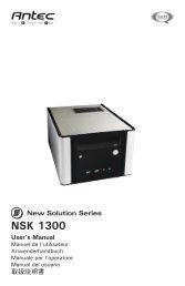
User's Manual Manuel de l'utilisateur - Manual del usuario - Antec
User's Manual Manuel de l'utilisateur - Manual del usuario - Antec
User's Manual Manuel de l'utilisateur - Manual del usuario - Antec
Create successful ePaper yourself
Turn your PDF publications into a flip-book with our unique Google optimized e-Paper software.
IEEE1394 (FireWire, I-Link) Connection<br />
There are six wires with connectors coming out from the front mounted IEEE1394 port of<br />
your case. They consist of 2 sets of twisted pair cables - TPA (Twisted Pair A) and TPB<br />
(Twisted Pair B), a power cable (VP), and a ground cable (VG).<br />
1. Locate and i<strong>de</strong>ntify the pin-out of the IEEE1394 port on your motherboard.<br />
2. Power Pin: Connect the VP connector to it.<br />
3. Ground Pin: Connect the VG connector to it.<br />
4. Data Pins: There are two sets of data pins. Each set consists of a plus and a minus<br />
pin. They are usually marked as TPA+ and TPA-, TPB+ and TPB-.<br />
a. Connect the TPA+ connector to the TPA+ data pin and TPA- connector to the<br />
TPA- data pin.<br />
b. Connect the TPB+ connector to the TPB+ data pin and TPB- connector to the<br />
TPB- data pin.<br />
3.5" Device Installation<br />
1. On the si<strong>de</strong>s of the front bezel there are two tabs. Press the tabs to remove the top<br />
half of the bezel.<br />
Note: You can see the external drive bays now. There are three 5.25"drive bays and<br />
one 3.5" drive bay assembly which can hold two 3.5" <strong>de</strong>vices.<br />
2. Unscrew the two silver thumbscrews located on the bottom of the drive bays and<br />
sli<strong>de</strong> out the 3.5" drive bay assembly.<br />
3. Install your floppy drive into the bottom drive bay. Mount the other 3.5" <strong>de</strong>vice<br />
into the top drive bay.<br />
4. Sli<strong>de</strong> the whole assembly back into the case and fasten it with the thumbscrews.<br />
5. Insi<strong>de</strong> the case, there is an internal 3.5" drive cage. It can hold three 3.5" <strong>de</strong>vices.<br />
Pull the quick release lever towards the rear of the case and release the cage. Put<br />
the cage on a flat surface. Note: If you want to have a cooling fan in the drive cage,<br />
you should install the fan before installing the drives.<br />
6. Mount your other 3.5" <strong>de</strong>vices into the drive cage.<br />
7. Sli<strong>de</strong> and lock the drive cage back into the case.<br />
8. Find a small 4-pin white connector on the power supply and connect it to the male<br />
4-pin connector on the floppy drive.<br />
9. Connect a large 4-pin white connector from the power supply to the male 4-pin<br />
connector on each of the other <strong>de</strong>vices.<br />
5.25" Device Installation<br />
1. There are three metal plates covering the 5.25 drive bays.<br />
2. Carefully use your hands to twist the metal plate back and forth until it breaks off.<br />
Note: Don't break off the plates covering the drive bays that you are not using now.<br />
Be careful of the newly exposed metal where the grills were attached as these areas<br />
are likely to be sharp.<br />
3. Take two of the Drive Rails and mount them onto the si<strong>de</strong>s of the 5.25" <strong>de</strong>vice.<br />
Make sure the metal portion is angled away from the <strong>de</strong>vice and facing forward.<br />
4. Sli<strong>de</strong> the <strong>de</strong>vice into the drive bay until you hear a clip.<br />
5. Mount the other <strong>de</strong>vices accordingly.<br />
6. Connect a large 4-pin white connector from the power supply to the male 4-pin<br />
connector on each of the <strong>de</strong>vices. After you have finished the installation, carefully<br />
use your thumbs to push the plastic drive bay covers off the bezel and attach the<br />
bezel back into the case. Like the metal plates, take off the covers that covering the<br />
drive bays you are using now.<br />
4<br />
IDE Cable Connection<br />
This is for IDE <strong>de</strong>vices only.<br />
After you have connected the <strong>de</strong>vices to the power supply, you need to connect the IDE<br />
cables between the <strong>de</strong>vices and the motherboard.<br />
1. For hard drives and CD-ROM's, use the 40-pin IDE ribbon cables. For floppy drives,<br />
use the 34-pin IDE ribbon cables. These should come with your <strong>de</strong>vices and have a<br />
red strip on si<strong>de</strong> indicating pin number 1. When you connect a ribbon cable to a<br />
<strong>de</strong>vice, make sure that the red strip is toward the power connector.<br />
2. The si<strong>de</strong> that attaches to <strong>de</strong>vices should be the si<strong>de</strong> that has 2 connectors. This will<br />
enable you to connect another <strong>de</strong>vice if you wish.<br />
3. Connect the far end of the cable to your motherboard on the IDE port, either IDE 1<br />
or IDE 2.<br />
Fan Installation<br />
The case comes preinstalled with one 80mm cooling fan in the rear and one 80mm cooling<br />
fan on the si<strong>de</strong> panel, or one 80mm cooling fan in the rear. The fans are installed in the<br />
manner that the air is blowing out of the case.<br />
Fan Only Connectors: We recommend our users to connect up to three case fans to the<br />
Fan Only connectors so the TruePower supply can control the speed of the fans. When the<br />
temperature insi<strong>de</strong> the case is low, the fans will rotate at a lower speed for quiet operation.<br />
When the temperature rises, the fans speed up to cool the case down. DO NOT connect<br />
other electronic equipment to the FAN ONLY power Connectors.<br />
Optional Cooling fans: The case has two optional 80mm cooling fans that can be installed<br />
in the front of the case. One of the optional fans is located insi<strong>de</strong> the 3.5" drive cage. You<br />
should install the fan first before you mount your drives into the cage. Install the fans at<br />
the manner that the air is bowing into the case to create a steady airflow from the front to<br />
the rear.<br />
Note: <strong>Antec</strong> cooling fans blow in the direction that the <strong>Antec</strong> logo is facing.<br />
1. With the <strong>Antec</strong> logo facing inwards, drop the fan into the fan bracket and push it in<br />
until it clips on.<br />
2. Connect a large 4-pin white connector from the power supply to the male 4-pin<br />
connector on each of the fans.<br />
Washable Air Filter Maintainence<br />
From time to time it will be necessary to wash the installed air filter. Not washing the<br />
air filter will result in higher system temperatures and stability problems. We recommend<br />
checking the air filter once a month initially. The frequency will change <strong>de</strong>pending on<br />
system usage (users who's systems run 24/7 will likely have to check/wash more often<br />
then those who don't use their systems every day).<br />
<strong>Antec</strong> Quality 3-Year parts and labor warranty (AQ3)<br />
See <strong>de</strong>tails at:<br />
http://www.antec-inc.com/support_warranty.html<br />
http://www.antec-europe.com/warranty_uk.html<br />
5


