MC 6800 DSC - President Electronics
MC 6800 DSC - President Electronics
MC 6800 DSC - President Electronics

You also want an ePaper? Increase the reach of your titles
YUMPU automatically turns print PDFs into web optimized ePapers that Google loves.
9. INSTALLATION<br />
1. The Set Installation<br />
The radio should be sited so that engine noise and vibration or other background noise does<br />
not make it difficult for the operator to hear.<br />
It is recommended that it is not installed where it will be exposed to continuous direct sunlight,<br />
as this will eventually damage the LCD display.<br />
As microphones and loudspeakers contain powerful magnets, the radio should not be installed<br />
within 1m (3ft 3in) of any compasses, whether magnetic or electronic.<br />
The fins on the back of the case act as a heat sink to dissipate heat generated by the set<br />
when in use, which maintains the high efficiency of the radio. The free circulation of air is<br />
essential - if mounting the radio in an enclosed space ensure that the space is vented.<br />
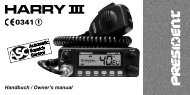
The <strong>MC</strong> <strong>6800</strong> <strong>DSC</strong> Radio is supplied with a reversible mounting bracket. This can be used to<br />
mount the radio on the chart table or on an overhead bulkhead (Fig A). The bracket is fixed in<br />
place using four screws (supplied). Before installing, ensure that there is at least 88mm(3.5<br />
in) verticals clearance and 127mm (5in) horizontal clearance behind the bracket to allow the<br />
radio to fit (Fig B). The rake angle of the radio can be adjusted by slackening the clamp.<br />
Desktop mounting Overhead mounting<br />
Desktop mounting<br />
Overhead mounting<br />
Mounting on dashboard<br />
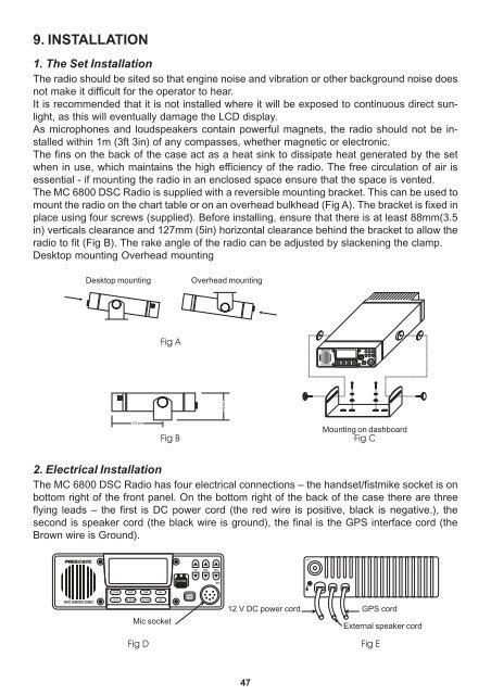
2. Electrical Installation<br />
The <strong>MC</strong> <strong>6800</strong> <strong>DSC</strong> Radio has four electrical connections – the handset/fistmike socket is on<br />
bottom right of the front panel. On the bottom right of the back of the case there are three<br />
flying leads – the first is DC power cord (the red wire is positive, black is negative.), the<br />
second is speaker cord (the black wire is ground), the final is the GPS interface cord (the<br />
Brown wire is Ground).<br />
Mic socket<br />
12 V DC power cord<br />
GPS cord<br />
External speaker cord<br />
47