GPS Series Amplifiers GPS Series Amplifiers - Peavey
GPS Series Amplifiers GPS Series Amplifiers - Peavey
GPS Series Amplifiers GPS Series Amplifiers - Peavey

You also want an ePaper? Increase the reach of your titles
YUMPU automatically turns print PDFs into web optimized ePapers that Google loves.
loudspeaker enclosures associated with this power amplifier must be in phase with any other<br />
loudspeaker enclosures associated with other power amps. If one loudspeaker system were to “push”<br />
while the other “pulls”, a serious sound “cancellation” could result. Changing the setting of the polarity<br />
switch has the same effect as reversing the polarity of the loudspeaker connections at the output.<br />
8. THRU<br />
Each channel has a female phone jack (8) labeled “thru”. This Thru jack offers very flexible patching<br />
capability. When the XLR input of the combination connectors (5 and 6) are used, this THRU jack is<br />
the output of the electronic balanced input circuitry, and as such can be used as a “line out” to connect<br />
to the other input jack on this amplifier or other amps in the same rack. Thus, one balanced mixer feed<br />
can be connected to the amp via the XLR connector and then further distributed (unbalanced) locally<br />
via the THRU jack. Alternatively, when the 1/4" phone jack input of the combination connectors<br />
(5 and 6) is used as the input, the THRU jack becomes a “bridged” input to it (similar to a Y-cord),<br />
again allowing this input signal to be patched to the other input jack on this amplifier or other amps in<br />
the system. IMPORTANT: The THRU jack is not intended to be an “input”, and inadvertent usage as<br />
such will result in excessive loading of the input source. Although not a catastrophic mistake, it will<br />
cause a significant reduction in “system gain” due to the loading, and will seriously limit the overall<br />
system performance.<br />
OUTPUTS<br />
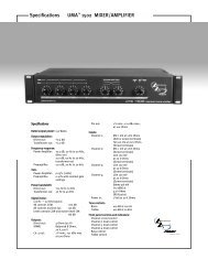
9. SPEAKER OUTPUT CONNECTORS<br />
Each <strong>GPS</strong> <strong>Series</strong> amplifier offers two separate output sections featuring parallel outputs. The type of<br />
output jack differs from model to model. Find the model and AC supply voltage of your unit to identify<br />
which description is applicable to your product.<br />
9<br />
<strong>GPS</strong> 900 OR <strong>GPS</strong> 1500 120 VAC (DOMESTIC) MODELS:<br />
These two models feature 1/4" output jacks located on the top-center of the rear panel. There are two<br />
parallel 1/4" jacks per channel which are labeled either “CHANNEL A” or “CHANNEL B”. In<br />
addition to the 1/4" output jacks, Binding Posts (10) are also provided for each channel.<br />
10<br />
10 11<br />
9<br />
7