GPS Series Amplifiers GPS Series Amplifiers - Peavey
GPS Series Amplifiers GPS Series Amplifiers - Peavey
GPS Series Amplifiers GPS Series Amplifiers - Peavey

You also want an ePaper? Increase the reach of your titles
YUMPU automatically turns print PDFs into web optimized ePapers that Google loves.
<strong>GPS</strong> <br />
<strong>Series</strong> <strong>Amplifiers</strong><br />
O P E R A T I N G G U I D E
Intended to alert the user to the presence of uninsulated “dangerous voltage” within the product’s<br />
enclosure that may be of sufficient magnitude to constitute a risk of electric shock to persons.<br />
Intended to alert the user of the presence of important operating and maintenance (servicing)<br />
instructions in the literature accompanying the product.<br />
CAUTION: Risk of electrical shock — DO NOT OPEN!<br />
CAUTION: To reduce the risk of electric shock, do not remove cover. No user serviceable parts inside. Refer<br />
servicing to qualified service personnel.<br />
WARNING: To prevent electrical shock or fire hazard, do not expose this appliance to rain or moisture. Before<br />
using this appliance, read the operating guide for further warnings.<br />
Este símbolo tiene el propósito, de alertar al usuario de la presencia de “(voltaje) peligroso” sin aislamiento<br />
dentro de la caja del producto y que puede tener una magnitud suficiente como para constituir<br />
riesgo de descarga eléctrica.<br />
Este símbolo tiene el propósito de alertar al usario de la presencia de instruccones importantes sobre la<br />
operación y mantenimiento en la información que viene con el producto.<br />
PRECAUCION: Riesgo de descarga eléctrica ¡NO ABRIR!<br />
PRECAUCION: Para disminuír el riesgo de descarga eléctrica, no abra la cubierta. No hay piezas útiles dentro.<br />
Deje todo mantenimiento en manos del personal técnico cualificado.<br />
ADVERTENCIA: Para evitar descargas eléctricas o peligro de incendio, no deje expuesto a la lluvia o humedad<br />
este aparato Antes de usar este aparato, Iea más advertencias en la guía de operación.<br />
Ce symbole est utilisé dans ce manuel pour indiquer à l’utilisateur la présence d’une tension dangereuse<br />
pouvant être d’amplitude suffisante pour constituer un risque de choc électrique.<br />
Ce symbole est utilisé dans ce manuel pour indiquer à l’utilisateur qu’il ou qu’elle trouvera d’importantes<br />
instructions concernant l’utilisation et l’entretien de l’appareil dans le paragraphe signalé.<br />
ATTENTION: Risques de choc électrique — NE PAS OUVRIR!<br />
ATTENTION: Afin de réduire le risque de choc électrique, ne pas enlever le couvercle. Il ne se trouve à l’intérieur<br />
aucune pièce pouvant être reparée par l’utilisateur. Confiez I’entretien et la réparation de l’appareil à un réparateur<br />
<strong>Peavey</strong> agréé.<br />
AVERTISSEMENT: Afin de prévenir les risques de décharge électrique ou de feu, n’exposez pas cet appareil à la<br />
pluie ou à l’humidité. Avant d’utiliser cet appareil, lisez attentivement les avertissements supplémentaires de ce<br />
manuel.<br />
Dieses Symbol soll den Anwender vor unisolierten gefährlichen Spannungen innerhalb des Gehäuses<br />
warnen, die von Ausreichender Stärke sind, um einen elektrischen Schlag verursachen zu können.<br />
Dieses Symbol soll den Benutzer auf wichtige Instruktionen in der Bedienungsanleitung aufmerksam<br />
machen, die Handhabung und Wartung des Produkts betreffen.<br />
VORSICHT: Risiko — Elektrischer Schlag! Nicht öffnen!<br />
VORSICHT: Um das Risiko eines elektrischen Schlages zu vermeiden, nicht die Abdeckung enfernen. Es befinden<br />
sich keine Teile darin, die vom Anwender repariert werden könnten. Reparaturen nur von qualifiziertem<br />
Fachpersonal durchführen lassen.<br />
ACHTUNG: Um einen elektrischen Schlag oder Feuergefahr zu vermeiden, sollte dieses Gerät nicht dem Regen<br />
oder Feuchtigkeit ausgesetzt werden. Vor Inbetriebnahme unbedingt die Bedienungsanleitung lesen.<br />
2
ENGLISH<br />
<strong>GPS</strong> SERIES<br />
POWER AMPLIFIERS<br />
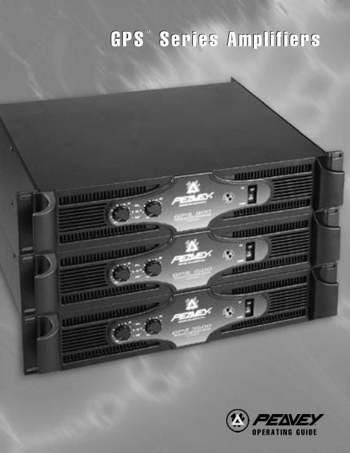
Congratulations on your purchase of the new <strong>GPS</strong> <strong>Series</strong> amplifier by <strong>Peavey</strong> Electronics. Years of power amp<br />
design and testing have produced a totally refined, dynamic power amp product line. The <strong>GPS</strong> <strong>Series</strong> consists<br />
of the <strong>GPS</strong> 900, <strong>GPS</strong> 1500, <strong>GPS</strong> 2600, <strong>GPS</strong> 3400 and <strong>GPS</strong> 3500. Each model features tunnel cooling, two<br />
variable-speed fans, initialization protection and DDT speaker protection. There are, however, differences<br />
between the various models such as output power and connections. This guide will describe each feature of<br />
your <strong>GPS</strong> <strong>Series</strong> amplifier and note the features common to specific models. The chart below offers a quick<br />
reference.<br />
<strong>GPS</strong> <strong>Series</strong> Power Amps<br />
SPECIFICATIONS<br />
<strong>GPS</strong> 900<br />
<strong>GPS</strong> 1500<br />
<strong>GPS</strong> 2600<br />
<strong>GPS</strong> 3500<br />
OUTPUT POWER<br />
Stereo mode, both channels driven<br />
2 ohms, 1 kHz, 0.1% THD<br />
4 ohms, 1 kHz, 0.1% THD<br />
8 ohms, 1 kHz, 0.1% THD<br />
450W RMS per channel<br />
330W RMS per channel<br />
200W RMS per channel<br />
750W RMS per channel<br />
550W RMS per channel<br />
320W RMS per channel<br />
1300W RMS per channel<br />
950W RMS per channel<br />
620W RMS per channel<br />
1700W RMS per channel<br />
1200W RMS per channel<br />
775W RMS per channel<br />
Bridge mode, mono<br />
4 ohms, 1 kHz, 0.1% THD<br />
8 ohms 1 kHz, 0.1% THD<br />
900W RMS<br />
660W RMS<br />
1500W RMS<br />
1100W RMS<br />
2600W RMS<br />
1900W RMS<br />
3500W RMS<br />
2400W RMS<br />
RATED OUTPUT POWER:<br />
Stereo mode, both channels driven<br />
4 ohms, 20 Hz to 20 kHz, 0.03% THD<br />
8 ohms, 20 Hz to 20 kHz, 0.02% THD<br />
4 ohms, 20 Hz to 20 kHz, 0.1% THD<br />
8 ohms, 20 Hz to 20 kHz, 0.08% THD<br />
300W RMS per channel<br />
1700W RMS per channel<br />
500W RMS per channel<br />
280W RMS per channel<br />
900W RMS per channel<br />
600W RMS per channel<br />
1050W RMS per channel<br />
750W RMS per channel<br />
SLEW RATE:(Typical value)<br />
Stereo mode, each channel<br />
Bridge mode, mono<br />
40 Volts per µsec<br />
80 Volts per µsec<br />
40 Volts per µsec<br />
80 Volts per µsec<br />
40 Volts per µsec<br />
80 Volts per µsec<br />
40 Volts per µsec<br />
80 Volts per µsec<br />
INPUT SENSITIVITY &<br />
IMPEDANCE:<br />
@ rated output power, 4 ohms<br />
unbalanced, 1/4" phone jack<br />
Balanced, XLR (polarity selectable)<br />
Overall system gain per channel<br />
0.87V RMS<br />
20 k ohms<br />
10 k ohms per leg<br />
40X (+32 dB)<br />
1.12V RMS<br />
20 k ohms<br />
10 k ohms per leg<br />
40X (+32 dB)<br />
1.54V RMS<br />
20 k ohms<br />
10 k ohms per leg<br />
40X (-32 dB)<br />
1.62V RMS<br />
20 k ohms<br />
10 k ohms per leg<br />
40X (+32 dB)<br />
FREQUENCY RESPONSE:<br />
Stereo mode, both channels driven<br />
+0m -1 dB @ 1 WRMS, 4 ohms<br />
+0, -0.2 dB @ rated output, 4 ohms<br />
5 Hz to 50 kHz<br />
20 Hz to 20 kHz<br />
5 Hz to 50 kHz<br />
20 Hz to 20 kHz<br />
5 Hz to 100 kHz<br />
10 Hz to 30 kHz<br />
5 Hz to 100 kHz<br />
10 Hz to 30 kHz<br />
DAMPING FACTOR: (Typical<br />
value)<br />
Stereo mode, both channels driven<br />
8 ohms<br />
Greater than 400<br />
Greater than 400<br />
Greater than 700<br />
Greater than 325<br />
Hum & Noise:<br />
Stereo mode, both channels driven<br />
Below rated output power, 4 ohms<br />
100 dB, unweighted<br />
100 dB, unweighted<br />
100 dB, unweighted<br />
100 dB, unweighted<br />
Specifications subject to change without notice.<br />
3
Please read this guide in its entirety. Pay close attention to the various warnings within as they pertain to the<br />
safety of you and your product. Each section will begin with a short description of the information you can<br />
expect to obtain within. This should help you to locate the material you are looking for in a timely manner.<br />
Once again, congratulations and thank you for buying <strong>Peavey</strong>!<br />
UNPACKING/REGISTRATION<br />
Inspect the amplifier during unpacking. If you find any damage, notify your dealer immediately. Be sure to<br />
save the carton and all packing materials. Should you ever need to ship the unit back to <strong>Peavey</strong> Electronics,<br />
one of its service centers, or the dealer, use only the original factory packing. Please fill out your registration<br />
card at this time. It is important that you complete the entire form and mail it to <strong>Peavey</strong> Electronics in order<br />
for your warranty to apply.<br />
INSTALLATION AND MOUNTING<br />
<strong>GPS</strong> <strong>Series</strong> amplifiers are 2-rack-space units that mount in a standard 19-inch rack. On all amplifiers, four<br />
front panel mounting holes are provided. Refer to the specifications for your specific model in this manual.<br />
QUICK START<br />
The following section lists the steps for basic usage. This is only a quick reference. It is very important that<br />
you read the entire manual in order to ensure the safe and optimum operation of your <strong>GPS</strong> <strong>Series</strong> amplifier.<br />
TO SET UP THE AMPLIFIER FOR BASIC USAGE:<br />
1. Rack mount the amplifier in the location where it is to be used, remembering to allow for adequate<br />
access and cooling space. For more information, see the section on Cooling Requirements.<br />
2. Make input connections, balanced or unbalanced, to the combination input connector on the rear panel.<br />
See the sections on The INs and OUTs of MODE SELECTION for more information.<br />
3. Connect speakers to the output jacks or binding posts. Be sure to make the correct output connections<br />
for stereo or bridged mono configuration. See the section on The INs and OUTs of MODE<br />
SELECTION for more information.<br />
4. Make power connections, allowing for proper current draw. See the section on AC Mains Circuit Size<br />
Requirements for more information.<br />
5. Turn down (fully counterclockwise) the two gain attenuators on the front panel. Turn the front panel<br />
AC switch to “ON,” and bring up the gain attenuators to the desired levels.<br />
AC POWER<br />
The following section will describe the AC power features of your <strong>GPS</strong> <strong>Series</strong> amplifier. AC power is a<br />
critical element in power amplification. Please read this section carefully, paying special attention to any<br />
warning signs. Refer to the diagram below and on page 8 to locate these features. Refer to page 7 for operation<br />
notes regarding AC power.<br />
NOTE: Always make connections to your <strong>GPS</strong> <strong>Series</strong> amplifier while the unit is turned off.<br />
1. REMOVABLE AC POWER CORD (Located on the rear of the unit)<br />
This receptacle is for the IEC line cord (included), which provides AC power to the unit. Connect the<br />
line cord to this connector and to a properly grounded AC supply. Damage to the equipment may occur<br />
if an improper line voltage is used. (See voltage marking on unit.) Never remove or cut the ground pin<br />
of the line cord plug. This unit is supplied with a properly rated line cord. When lost or damaged,<br />
replace this cord with one of the proper ratings.<br />
4
2. AC POWER SWITCH (Located on the front of the unit. See diagram on page 9.)<br />
A two-position power switch is on the right side of the front panel. With the top portion of the switch<br />
pushed to the “IN” position the amplifier is “ON”. Press the bottom portion of the switch to the<br />
“IN” position to turn the unit “OFF”.<br />
3. POWER LED (Located on the front of the unit. See diagram on page 9.)<br />
The Power LEDs illuminate to indicate the amplifier is turned on.<br />
REAR PANEL<br />
1<br />
4<br />
6 7 5<br />
THE INS AND OUTS OF MODE<br />
SELECTION<br />
Once you have provided proper AC power to the amplifier, you may now connect to the inputs and outputs.<br />
Remember to do this while the power to the unit is turned off (Power LED are not lit). The rear panel of your<br />
<strong>GPS</strong> <strong>Series</strong> amplifier provides a central location for all input and output connections. Regardless of the <strong>GPS</strong><br />
model, all input connections are located at the bottom-center portion of the rear panel and all output<br />
connections are located at the top-center portion. In addition, your amplifier can operate in either stereo or<br />
bridged (mono) mode. All <strong>GPS</strong> <strong>Series</strong> amplifiers have DDT compression. However, only <strong>GPS</strong> models 900 and<br />
1500 have a switch to defeat this feature. This section will describe these areas of your <strong>GPS</strong> <strong>Series</strong> amplifier in<br />
detail.<br />
MODE SELECTION<br />
4. MODE SWITCH<br />
This switch determines which mode your amplifier will operate in. Before connecting your input signal<br />
and speaker cables to the amp, you must determine how you want the amp to function. Two modes of<br />
operation are offered on your amplifier, stereo or bridged (seperate).<br />
STEREO:<br />
When we use the term “stereo” we are referring to two channels, not necessarily left and right.<br />
Therefore, in “stereo” mode there are essentially two power amps regardless of input type. You may<br />
use a stereo input, one stereo input to each channel of the <strong>GPS</strong>, or you may send two mono inputs to<br />
the <strong>GPS</strong> in the same manner. A good example of two separate inputs would be the use of one channel<br />
for mono mains and one channel for mono monitor signals. In order to select the “stereo” mode of<br />
operation you must place the Mode Switch in the “out” position. In this mode, Channel A Output is<br />
supplied by the Channel A Input. Channel B Output is supplied by Channel B Input.<br />
BRIDGED OR MONO:<br />
In the “bridge” mode the two channels of the amplifier combine to form a single mono channel. The<br />
benefit of using your amplifier in this mode is that the power is doubled. Refer to the specifications in<br />
this manual for detailed output power specs on your specific model. To use the <strong>GPS</strong> <strong>Series</strong> amp in<br />
5<br />
8
“bridge” mode, place the Mode Switch to the “in” position where the switch remains down. The amp is<br />
now a mono amplifier and only requires a single input. Plug your input signal into Channel A only for<br />
“bridge” mode operation. Channel B input must not have anything connected.<br />
NOTE FOR <strong>GPS</strong> 900 AND 1500:<br />
When these models are switched to “bridge” mode, the Power LED (3) for Channel B<br />
will no longer illuminate.<br />
NOTE: Refer to the Outputs section for an explanation of how the Mode Switch affects the speaker<br />
outputs.<br />
INPUTS<br />
5. CHANNEL A COMBINATION INPUT<br />
<strong>GPS</strong> 900 AND 1500<br />
These <strong>GPS</strong> <strong>Series</strong> amplifiers offer both XLR electronic balanced and phone jack quasi-balanced<br />
inputs for each channel using Neutrik ® ’s new “combo” connector to save panel space.<br />
The female XLR inputs are connected to dual OP AMP circuitry which offers very low noise and<br />
extremely high common mode rejection ratio to minimize outside interference!<br />
The female 1/4" phone jack input in the center of the “combo” connectors are also connected to a<br />
unique “quasi-balanced” input circuitry. When used, these 1/4" jacks are not “chassis grounded” but<br />
connected to ground through a relatively low impedance circuit which is part of a "ground loop"<br />
elimination circuit associated with the input. This will normally allow "hum free" operation when<br />
relatively short 1/4" cable patches are made to this input by various outputs from other equipment that<br />
share the same rack with this amp. This “quasi-balanced” circuit is “automatic”, and is virtually<br />
invisible in normal usage. It cannot be defeated. Use only a two-conductor (TS) phone plug when<br />
connecting to the 1/4" input of this connector.<br />
<strong>GPS</strong> 2600, 3400 AND 3500<br />
These <strong>GPS</strong> <strong>Series</strong> amplifiers offer both XLR electronic balanced and phone jack balanced/unbalanced<br />
inputs for each channel using Neutrik's new “combo” connector to save panel space.<br />
The female 1/4" phone jack input in the center of the “combo” connectors is also connected to a<br />
unique balanced/unbalanced input circuitry. When used, these 1/4" jacks can accept both unbalanced<br />
two-conductor (TS) and balanced three-conductor (TRS) inputs. Balanced operation is always<br />
recommended for optimum signal-to-noise. If unbalanced operation is a required, always keep the<br />
input cable to a minimum length to avoid excessive noise.<br />
6. CHANNEL B COMBINATION INPUT<br />
This connector is identical to the Channel A Combination Input (5) except it is not used during<br />
“bridge” mode [See Mode Switch (4).]<br />
7. INPUT POLARITY<br />
Located between the Channel A and Channel B Inputs is a recessed Input Polarity switch (7) that<br />
allows the user to select the desired polarity (phase) of the XLR inputs. This switch is a push-push type<br />
and a small diameter “tool” is required to select the desired position. Set to the out (default) position,<br />
the polarity is pin #3 positive, pin #2 negative, and pin #1 ground. This is the polarity found on most<br />
<strong>Peavey</strong> power amplifiers. Although this is not the world “standard” (IEC) polarity, it was chosen by<br />
<strong>Peavey</strong> more than 20 years ago, and thus we offer this polarity to be consistent with products both past<br />
and present. If this amplifier is used with other competitive products which use the IEC standard<br />
polarity, then the “in” position of switch (7) should be selected yielding pin #2 positive, pin #3<br />
negative, and pin #1 ground. As with any electronic gear, polarity (phasing) is important because the<br />
6
loudspeaker enclosures associated with this power amplifier must be in phase with any other<br />
loudspeaker enclosures associated with other power amps. If one loudspeaker system were to “push”<br />
while the other “pulls”, a serious sound “cancellation” could result. Changing the setting of the polarity<br />
switch has the same effect as reversing the polarity of the loudspeaker connections at the output.<br />
8. THRU<br />
Each channel has a female phone jack (8) labeled “thru”. This Thru jack offers very flexible patching<br />
capability. When the XLR input of the combination connectors (5 and 6) are used, this THRU jack is<br />
the output of the electronic balanced input circuitry, and as such can be used as a “line out” to connect<br />
to the other input jack on this amplifier or other amps in the same rack. Thus, one balanced mixer feed<br />
can be connected to the amp via the XLR connector and then further distributed (unbalanced) locally<br />
via the THRU jack. Alternatively, when the 1/4" phone jack input of the combination connectors<br />
(5 and 6) is used as the input, the THRU jack becomes a “bridged” input to it (similar to a Y-cord),<br />
again allowing this input signal to be patched to the other input jack on this amplifier or other amps in<br />
the system. IMPORTANT: The THRU jack is not intended to be an “input”, and inadvertent usage as<br />
such will result in excessive loading of the input source. Although not a catastrophic mistake, it will<br />
cause a significant reduction in “system gain” due to the loading, and will seriously limit the overall<br />
system performance.<br />
OUTPUTS<br />
9. SPEAKER OUTPUT CONNECTORS<br />
Each <strong>GPS</strong> <strong>Series</strong> amplifier offers two separate output sections featuring parallel outputs. The type of<br />
output jack differs from model to model. Find the model and AC supply voltage of your unit to identify<br />
which description is applicable to your product.<br />
9<br />
<strong>GPS</strong> 900 OR <strong>GPS</strong> 1500 120 VAC (DOMESTIC) MODELS:<br />
These two models feature 1/4" output jacks located on the top-center of the rear panel. There are two<br />
parallel 1/4" jacks per channel which are labeled either “CHANNEL A” or “CHANNEL B”. In<br />
addition to the 1/4" output jacks, Binding Posts (10) are also provided for each channel.<br />
10<br />
10 11<br />
9<br />
7
All other <strong>GPS</strong> models:<br />
These models offer dual Speakon ® Quick Connectors. The Speakon ® is a four-wire connector with the<br />
connections labeled as 1+, 1-, 2+ and 2-. The Speakon connectors found on your <strong>GPS</strong> <strong>Series</strong> amplifier<br />
are connected with pins 1+ and 2+ wired in parallel to the positive output. Pins 1- and 2- are wired in<br />
parallel to the negative output. This is typical for each channel.<br />
NOTE: Consult your loud speaker specifications to determine the wiring configuration that will best<br />
suit your system. The diagrams on pages 13 and 14 display the recommended hookup for your <strong>GPS</strong><br />
<strong>Series</strong> amplifier. In addition to the Speakon ® Quick Connectors, Binding Posts (10) are also provided<br />
for each channel.<br />
10. BINDING POST OUTPUT CONNECTORS<br />
Five-way binding post speaker outputs can be found on each channel regardless of model. For each<br />
channel, the outputs are in parallel, hence the speaker connection cables can be terminated with banana<br />
plugs or stripped wires for use in the binding post terminals as well as the output connectors (9). For<br />
sustained high power applications, the use of the binding post terminals is recommended; however,<br />
care must be exercised to assure the correct speaker polarity. The red binding posts are the signal<br />
outputs from each channel, and the black binding posts are chassis ground. The red binding post should<br />
be connected to the positive inputs of the associated loudspeakers. For “bridge” mode operation, only<br />
the red binding posts are used, and the associated loudspeaker load is connected between the two red<br />
binding posts. The red binding post associated with Channel A should be considered the positive output<br />
for the system and thus should be connected to the positive input of the associated loudspeaker system.<br />
WARNING: Regardless of what connections are used, the minimum parallel speaker load should<br />
always be limited to 2 ohms per channel or 4 ohms “bridge” mode for any application. Operation at<br />
loads of 4 ohms per channel or 8 ohms “bridge” mode is more desirable for sustained operation<br />
applications due to the fact that the amplifier will run much cooler at this loading. Operation above 4<br />
ohms per channel and even open circuit conditions can always be considered safe; however, sustained<br />
operation at loads below 2 ohms could result in temporary amplifier shut down due to the thermal<br />
limits fault circuitry.<br />
DDT COMPRESSION<br />
11. DDT DEFEAT<br />
This switch is used to defeat the DDT compression used to protect against signal clipping. Only the<br />
<strong>GPS</strong> 900 and 1500 models offer this feature. It is recommended to leave the DDT compression<br />
enabled at all times to protect your speakers from damaging square waves. The DDT function is<br />
disabled when the switch is pressed to the “in” position. The DDT LEDs (12) will illuminate when<br />
DDT compression is occurring in that particular channel.<br />
FRONT PANEL CONTROLS/INDICATORS<br />
The following section describes the controls and indicators found on the front panel of your <strong>GPS</strong> <strong>Series</strong><br />
amplifier. The Power Switch and LED are explained in a previous section, AC Power.<br />
8
15 13 12 3<br />
2<br />
15<br />
14 14<br />
12. DDT LEDs<br />
The DDT LEDs will illuminate when signal compression is occurring in that channel. If you have a<br />
<strong>GPS</strong> 900 or 1500 and you have the DDT compression defeated, these LED will indicate the channel<br />
is clipping.<br />
13. SIGNAL LEDs<br />
Each channel has a Signal LED, which comes on when the amplifier channel output exceeds 1 volt.<br />
14. INPUT GAIN<br />
Each channel has an Input Gain control used to adjust the gain of the input signal. Maximum power<br />
amplifier input gain (minimum sensitivity) is achieved at the full clockwise setting (30 dB or 40x).<br />
This setting yields maximum mixer/system headroom. A setting of less than full clockwise will yield<br />
lower system noise at the expense of headroom.<br />
15. FAN GRILL (located on front and rear panel)<br />
Two continuously variable-speed DC fans supply cool air to the amplifier.<br />
<strong>GPS</strong> 900 AND 1500<br />
The fans operate at a quiet, low speed when the unit is turned on. The speed of the fans increase as the<br />
amplifier heatsinks require cooling. (See Operation Notes.)<br />
<strong>GPS</strong> 2600, 3400 AND 3500<br />
The fans do not operate when the unit is first turned on. The operation and speed of the fans are<br />
temperature dependent and change as the amplifier heatsinks require cooling. (See Operation Notes.)<br />
DO NOT BLOCK THIS EXHAUST PORT! During the operation of your <strong>GPS</strong> <strong>Series</strong> amplifier, it<br />
will require fresh air intake in order for the tunnel cooling to function properly. Blocking this air<br />
exhaust port or the air intake ports on the rear could result in thermal shutdown of your amplifier.<br />
OPERATION NOTES<br />
AC MAINS CIRCUIT SIZE REQUIREMENTS.<br />
Power requirements for the <strong>GPS</strong> <strong>Series</strong> amplifiers are rated at “typical” music conditions. The maximum<br />
power current draw rating is limited by the amplifier’s circuit breaker. Consult the specification sheet for the<br />
current that each amplifier will demand. AC mains voltage must be the same as that indicated on the back of<br />
the amplifier. Damage caused by connecting the amplifier to improper AC voltage is not covered by any<br />
warranty.<br />
9
LINE CORD<br />
For your safety, we have incorporated a removable 3-wire line (mains) cable with proper grounding<br />
facilities. It is not advisable to remove the ground contact under any circumstances. If it is necessary to<br />
use the equipment without proper grounding facilities, suitable grounding adapters should be used. Less noise<br />
and greatly reduced shock hazard exists when the unit is operated with the proper grounded receptacles.<br />
NOTE: Always turn off the amplifier before making audio connections. As an extra precaution, have the input<br />
attenuator turned down during power-up.<br />
COOLING REQUIREMENTS (<strong>GPS</strong> 900 and 1500)<br />
These <strong>GPS</strong> <strong>Series</strong> amplifiers use a forced-air cooling system to maintain a low, even operating temperature.<br />
Cooling air is drawn by synchronized, variable-speed fans mounted on the back panel, and exhausts through<br />
slots on the front panel. The fans will remain at low speed until internal operating temperature rises above<br />
45 0 C. Make sure that there is enough space around the back of the amplifier to allow air to enter. The normal<br />
operating temperature is 55 0 C. This is a very cool temperature when compared to most amplifier standards.<br />
What this means to you is a noticeable increase in product life. On the <strong>GPS</strong> 900 and 1500 models, the fans<br />
will turn on simultaneously when temperature activated.<br />
COOLING REQUIREMENTS (All models except <strong>GPS</strong> 900 and 1500)<br />
These <strong>GPS</strong> <strong>Series</strong> amplifiers use a forced-air cooling system to maintain a low, even operating temperature.<br />
Cooling air is drawn by continuously variable speed fans mounted on the back panel, and exhausts through<br />
slots on the front panel. The fan will remain inactive until internal operating temperature rises above 45 0 C.<br />
Make sure that there is enough space around the back of the amplifier to allow air to enter. The normal<br />
operating temperature is 55 0 C. This is a very cool temperature when compared to most amplifier standards.<br />
What this means to you is a noticeable increase in product life.<br />
NOTE: If the amplifier is rack-mounted, do not use doors or covers on the front or back while the unit is<br />
in operation. Whatever type of rack you are using, make sure that heated air can escape freely, and that<br />
there is no resistance to the intake of cool air through the back grill. Intake and exhaust air must flow without<br />
resistance.<br />
INPUT CONNECTIONS<br />
The input connector accepts balanced and unbalanced audio signals. For use with an unbalanced source, tie the<br />
inverting (-) input to ground by installing a jumper to the signal ground connection. If the inverting input is<br />
left floating, a 6 dB loss in gain will result.<br />
SIGNAL MODE CONFIGURATION<br />
<strong>GPS</strong> <strong>Series</strong> amplifiers are configured for two-channel (stereo) or bridged mode operation at the input<br />
connectors and via Mode Switch. To send the same signal to both channels, connect the input signal to<br />
Channel A via the input connector. Run a jumper from the Thru jack of Channel A to the input of Channel B.<br />
Both channels then share Channel A’s input signal, but will operate independently. Speakers are connected as<br />
in two-channel (stereo) mode.<br />
Bridged mode converts the amplifier into a single-channel unit with a power rating equal to the sum of both<br />
channels’ power ratings, and at a load rating of twice that of the single-channel rating. In bridged mode, the<br />
channels operate at opposite polarity of each other so that one channel “pushes” and the other “pulls” equally.<br />
Signal is connected to the Channel A Input connector. The speakers are connected only to the designated “+”<br />
output terminals. Never ground either side of the speaker cable when the amplifier is in bridged mode, as both<br />
sides are “hot”. For <strong>GPS</strong> <strong>Series</strong> amplifiers, the minimum nominal load impedance in bridged mode is 4 ohms;<br />
this is the equivalent of driving both channels at 2 ohms. Driving loads of less than 4 ohms may activate the<br />
thermal protect circuitry.<br />
10
NOTE: Regardless of operating mode, NEVER connect amplifier outputs together!<br />
SPEAKER OUTPUT CONNECTIONS<br />
Speakers are connected using the output connectors on the rear of your amplifier. Make sure the amplifier is<br />
turned off before you change any output connections. Refer to the diagram on page 14 to view the wiring<br />
configuration of the Speakon connectors if your model utilizes them. Consult the Wire Gauge Chart on page<br />
14 to find a suitable wire gauge and minimize losses of power in the speaker cables. Also, make sure that the<br />
load impedance is not lower than that rated for the amplifier.<br />
PROTECTION FEATURES<br />
The <strong>GPS</strong> <strong>Series</strong> incorporates protection features derived from <strong>Peavey</strong>’s extensive experience with reliability.<br />
The amplifiers are ruggedly built from high quality components and feature comprehensive protection circuits<br />
to protect your amplifier from those “real world” occurrences.<br />
DDT<br />
At the amplifier’s full power, or clipping point, the channel gain will automatically be reduced, guarding the<br />
loudspeakers against damaging high power and continuous square waves that would otherwise be produced.<br />
This is indicated by illumination of the DDT LED. Operation is virtually transparent in use and full signal<br />
bandwidth is maintained. However, if you have a <strong>GPS</strong> 900 or 1500 and choose to defeat the DDT compression<br />
function, this will not apply and clipping may occur.<br />
LOAD FAULT CORRECTION <br />
LFC (Load Fault Correction ) is an innovative circuit that will instantaneously reduce channel gain to allow<br />
the amplifier to operate at a safe level into an abnormal load. Moderate activation of LFC is inaudible in<br />
normal use. In addition, if extreme low impedance or a short circuit is encountered during high signal level<br />
conditions, the amplifier’s output relay will open.<br />
INITIALIZATION PROTECTION (IP )<br />
IP operates every time the amplifier is turned on, or after a protect condition. During turn-on, the amplifier<br />
goes into protect mode and leaves the speaker load disconnected until the amplifier determines that the<br />
operating status is normal. The IP circuit attenuates the signal during the initial turn-on or protect operation.<br />
After relay release, channel gain gradually increases to the attenuator setting to avoid unnecessary stress on the<br />
loudspeakers.<br />
THERMAL PROTECTION<br />
If the heatsink temperature or power transformer reaches an abnormally high temperature, the amplifier will<br />
protect itself by disconnecting the speaker load until the amplifier returns to a normal temperature. During this<br />
time, the Power LEDs will not illuminate for that particular channel, and the cooling fan(s) will operate at<br />
maximum speed.<br />
SHORT CIRCUIT<br />
If an output is shorted, the LFC , speaker relay and thermal circuits will automatically protect the amplifier.<br />
The LFC circuit senses the short circuit as an abnormal load condition and reduces the channel gain to a safe<br />
level for the load. In extreme or severe conditions, the speaker relays will disconnect the load and initiate a<br />
power-on start-up sequence.<br />
DC VOLTAGE PROTECTION<br />
If an amplifier channel detects DC voltage or subsonic signals at its output terminals, the speaker relay will<br />
immediately open to prevent loudspeaker damage.<br />
Neutrik ® is a registered trademark of Neutrik AG<br />
Speakon ® is a registered trademark of Neutrik AG.<br />
11
<strong>GPS</strong> <br />
<strong>Series</strong> <strong>Amplifiers</strong><br />
Recommended Connection for Stereo Mode<br />
SP 7G<br />
<strong>GPS</strong> 900/1500<br />
150VAC Units Only<br />
SP 7G<br />
To Additional Amplifier Input<br />
Channel B Input Source<br />
Channel A Input Source<br />
To Additional Amplifier Input<br />
NOTE: Minimum Load<br />
Impedance is 2 Ohms.<br />
1/4" jacks are wired in parallel<br />
with binding post.<br />
Tip = Positive<br />
Ring = Negative<br />
DTH ® 4215F<br />
All other <strong>GPS</strong> Models<br />
DTH ® 4215F<br />
To Additional Amplifier Input<br />
Channel B Input Source<br />
Channel A Input Source<br />
To Additional Amplifier Input<br />
NOTE: Minimum Load<br />
Impedance is 2 Ohms.<br />
Speaker connectors are wired in<br />
parallel with binding posts.<br />
Pins (1+) and (2+) are wired positive.<br />
Pins (1-) and (2-) are wired negative.<br />
NOTE: Always use a balanced input source if available.<br />
12
<strong>GPS</strong> <br />
<strong>Series</strong> <strong>Amplifiers</strong><br />
Recommended Connection for Bridged Mode<br />
(-)<br />
To negative input<br />
terminal of speaker<br />
<strong>GPS</strong> 900/1500<br />
150VAC Units Only<br />
(+)<br />
To positive input<br />
terminal of speaker<br />
Switch “in” for<br />
Bridge Mode<br />
Input Source<br />
NOTE: Minimum Load<br />
Impedance is 4 Ohms.<br />
To Additional<br />
Amplifier Input<br />
(-)<br />
To negative input<br />
terminal of speaker<br />
All other <strong>GPS</strong> Models<br />
(+)<br />
To positive input<br />
terminal of speaker<br />
Switch “in” for<br />
Bridge Mode<br />
Input Source<br />
NOTE: Minimum Load<br />
Impedance is 4 Ohms.<br />
To Additional<br />
Amplifier Input<br />
NOTE: Always use a balanced input source if available.<br />
13
WIRE GAUGE CHART<br />
Stranded Power Power Power<br />
Cable Wire Loss Loss Loss<br />
Length Gauge Into Into Into<br />
(Feet) (AWG) 8 ohms 4 ohms 2 ohms<br />
5' 18 AWG .79% 1.58% 3.16%<br />
16 .05 1.0 2.0<br />
14 .31 .62 1.24<br />
12 .20 .40 .80<br />
10 .125 .25 .50<br />
10' 18 AWG 1.58% 3.16% 6.32%<br />
16 1.0 2.0 4.0<br />
14 .62 1.25 2.50<br />
12 .40 .80 1.6<br />
10 .25 .50 1.0<br />
40' 18 AWG 8% 12.6% 25.2%<br />
16 4.0 8.0 16.0<br />
14 2.5 5.0 10<br />
12 1.60 3.2 6.4<br />
10 1.0 2.0 4.0<br />
8 .625 1.25 2.50<br />
80' 16 AWG 8.0% 16.0% 32.0%<br />
14 5.0 10.0 20.0<br />
12 3.2 6.4 12.8<br />
10 2.0 4.0 8.0<br />
14
<strong>GPS</strong> 900 SPECIFICATIONS<br />
OUTPUT POWER: (Typical value)<br />
Stereo mode, both channels driven<br />
2 ohms, 1 kHz, .1 THD - 450 WRMS per channel<br />
4 ohms, 1 kHz, .1 THD - 330 WRMS per channel<br />
8 ohms, 1 kHz, .1 THD - 200 WRMS per channel<br />
Bridge mode, mono<br />
4 ohms, 1 kHz, .1 THD - 900 WRMS<br />
8 ohms, 1 kHz, .1 THD - 660 WRMS<br />
RATED OUTPUT POWER:<br />
Stereo mode, both channels driven<br />
4 ohms, 20 Hz to 20 kHz,0.03% THD - 300 WRMS per channel<br />
8 ohms, 20 Hz to 20 KHz,0.02% THD - 170 WRMS per channel<br />
SLEW RATE: (Typical value)<br />
Stereo mode, each channel<br />
Bridge mode, mono<br />
INPUT SENSITIVITY AND IMPEDANCE:<br />
Input attenuator set @ FCW<br />
@ rated output power, 4 ohms<br />
Unbalanced, 1/4" phone jack<br />
Balanced, XLR (phase selectable)<br />
Overall system gain per channel<br />
- 40 Volts per usec<br />
- 80 Volts per usec<br />
- 0.90 VRMS (-1 dBV)<br />
- 20 k ohms<br />
- 10 k ohms per leg<br />
- 40X (+32 dB)<br />
FREQUENCY RESPONSE: (Typical)<br />
Stereo mode, both channels driven<br />
+0,-1 dB, 1 WRMS, 4 ohms - 5 Hz to 50 kHz<br />
+0,-0.2 dB @ rated output, 4 ohms - 20 Hz to 20 kHz<br />
DAMPING FACTOR: (Typical value)<br />
Stereo mode, both channels driven<br />
8 ohms, 1 kHz - Greater than 400<br />
HUM AND NOISE:<br />
Below rated output power, 4 ohms<br />
POWER CONSUMPTION:<br />
@ 1/8 rated power @ 2 ohms<br />
WEIGHT:<br />
Stereo mode, both channels driven<br />
- 100 dB @ 120 volts<br />
Stereo mode, both channels driven<br />
- 540 watts @ 120 VAC<br />
- 35.8 lbs. (16.2 kg)<br />
Specifications subject to change without notice.<br />
15
<strong>GPS</strong> 1500 SPECIFICATIONS<br />
OUTPUT POWER: (Typical value)<br />
Stereo mode, both channels driven<br />
2 ohms, 1 kHz, .1 THD - 750 WRMS per channel<br />
4 ohms, 1 kHz, .1 THD - 550 WRMS per channel<br />
8 ohms, 1 kHz, .1 THD - 320 WRMS per channel<br />
Bridge mode, mono<br />
4 ohms, 1 kHz, .1 THD - 1,500 WRMS<br />
8 ohms, 1 kHz, .1 THD - 1,100 WRMS<br />
RATED OUTPUT POWER:<br />
Stereo mode, both channels driven<br />
4 ohms, 20 Hz to 20 kHz,0.03% THD - 500 WRMS per channel<br />
8 ohms, 20 Hz to 20 kHz,0.02% THD - 280 WRMS per channel<br />
SLEW RATE: (Typical value)<br />
Stereo mode, each channel<br />
Bridge mode, mono<br />
INPUT SENSITIVITY and IMPEDANCE:<br />
Input attenuator set @ FCW<br />
@ rated output power, 4 ohms<br />
Unbalanced, 1/4" phone jack<br />
Balanced, XLR (phase selectable)<br />
Overall system gain per channel<br />
- 40 Volts per usec<br />
- 80 Volts per usec<br />
- 1.17 VRMS (+1 dBV)<br />
- 20 k ohms<br />
- 10 k ohms per leg<br />
- 40X (+32 dB)<br />
FREQUENCY RESPONSE: (Typical)<br />
Stereo mode, both channels driven<br />
+0,-1 dB, 1 WRMS, 4 ohms - 5 Hz to 50 kHz<br />
+0,-0.2 dB @ rated output, 4 ohms - 20 Hz to 20 kHz<br />
DAMPING FACTOR: (Typical value)<br />
Stereo mode, both channels driven<br />
8 ohms, 1 kHz - Greater than 400<br />
HUM AND NOISE:<br />
Below rated output power, 4 ohms<br />
POWER CONSUMPTION:<br />
@ 1/8 rated power @ 2 ohms<br />
WEIGHT:<br />
Stereo mode, both channels driven<br />
- 100 dB, unweighted<br />
Stereo mode, both channels driven<br />
- 1080 watts @ 120 VAC<br />
- 39.2 lbs. (17.9 kg)<br />
Specifications subject to change without notice.<br />
16
<strong>GPS</strong> 2600 SPECIFICATIONS<br />
Rated Power (2 x 2 ohms)<br />
Rated Power (2 x 4 ohms)<br />
Rated Power (2 x 8 ohms)<br />
Rated Power (1 x 2 ohms)<br />
Rated Power (1 x 4 ohms)<br />
Rated Power (1 x 8 ohms)<br />
Minimum Load Impedance<br />
Maximum RMS Voltage Swing<br />
Frequency Response<br />
Power Bandwidth<br />
T.H.D. (2 x 2 ohms)<br />
T.H.D. (2 x 4 ohms)<br />
T.H.D. (2 x 8 ohms)<br />
Input CMRR<br />
Voltage Gain<br />
Crosstalk<br />
Hum and Noise<br />
Power Consumption<br />
Slew Rate<br />
Damping Factor (8 ohms)<br />
SMPTE IMD<br />
Input Sensitivity (x 40)<br />
Input Impedance<br />
Current Draw @ 1/8 power@ 2 ohms<br />
Cooling<br />
Controls<br />
Indicator LEDs<br />
Protection<br />
Connectors<br />
Construction<br />
Dimensions<br />
Weight<br />
- 1,300 watts @ 1 kHz both channels driven at
<strong>GPS</strong> 3400 SPECIFICATIONS<br />
Rated Power (2 x 2 ohms):<br />
Rated Power (2 x 4 ohms):<br />
Rated Power (2 x 8 ohms):<br />
Rated Power (1 x 2 ohms):<br />
Rated Power (1 x 4 ohms):<br />
Rated Power (1 x 8 ohms):<br />
T.H.D. (2 x 2 ohms):<br />
T.H.D. (2 x 4 ohms):<br />
T.H.D. (2 x 8 ohms):<br />
Input CMRR:<br />
Voltage Gain:<br />
Crosstalk:<br />
Hum and Noise:<br />
Power Consumption:<br />
Slew Rate:<br />
Damping Factor (8 ohms):<br />
SMPTE IMD:<br />
Input Sensitivity (x 40):<br />
Input Impedance:<br />
Current Draw @ 1/8 rated<br />
power @ 2 ohms:<br />
Cooling:<br />
Controls:<br />
Indicator LEDs:<br />
Protection:<br />
Connectors:<br />
Construction:<br />
Dimensions:<br />
Weight:<br />
1,700 watts @ 1 kHz both channels driven at
<strong>GPS</strong> 3500 SPECIFICATIONS<br />
Rated Power (2 x 2 ohms):<br />
Rated Power (2 x 4 ohms):<br />
Rated Power (2 x 8 ohms):<br />
Rated Power (1 x 2 ohms):<br />
Rated Power (1 x 4 ohms):<br />
Rated Power (1 x 8 ohms):<br />
Minimum Load Impedance:<br />
Maximum RMS Voltage Swing:<br />
Frequency Response:<br />
Power Bandwidth:<br />
T.H.D. (2 x 2 ohms):<br />
T.H.D. (2 x 4 ohms):<br />
T.H.D. (2 x 8 ohms):<br />
Input CMRR:<br />
Voltage Gain:<br />
Crosstalk:<br />
Hum and Noise:<br />
Power Consumption:<br />
Slew Rate:<br />
Damping Factor (8 ohms):<br />
SMPTE IMD:<br />
Input Sensitivity (x 40):<br />
Input Impedance:<br />
Current Draw @ 1/8 rated<br />
power @ 2 ohms:<br />
Cooling:<br />
Controls:<br />
Indicator LEDs:<br />
Protection:<br />
Connectors:<br />
Construction:<br />
Dimensions:<br />
Weight:<br />
1750 watts @ 1 kHz both channels driven at
ESPAÑOL<br />
Serie <strong>GPS</strong> <br />
Amplificadores de Potencia<br />
Felicidades por tu compra del nuevo amplificador de potencia de la serie <strong>GPS</strong> de <strong>Peavey</strong> Electronics. Años de<br />
diseño y pruebas han producido una línea de amplificadores dinámicos completamente refinada. La serie <strong>GPS</strong><br />
consiste de los modelos <strong>GPS</strong> 900, <strong>GPS</strong> 1500, <strong>GPS</strong> 2600, <strong>GPS</strong> 3400 y <strong>GPS</strong> 3500. Cada modelo incluye<br />
enfriamiento por túnel, ventiladores variables de dos velocidades, protección de iniciación y protección de<br />
bocinas DDT‘. Pero también hay diferencias entre los modelos, como las diferencias de potencia y conexiones.<br />
Esta guía describirá todas las características de tu modelo <strong>GPS</strong>, y también hará nota de las características<br />
comunes entre los otros modelos <strong>GPS</strong>. La gráfica inferior ofrece una guía de referencia rápida.<br />
SPECIFICATIONS<br />
<strong>GPS</strong> 900<br />
<strong>GPS</strong> 1500<br />
<strong>GPS</strong> 2600<br />
<strong>GPS</strong> 3500<br />
OUTPUT POWER<br />
Stereo mode, both channels driven<br />
2 ohms, 1 kHz, 0.1% THD<br />
4 ohms, 1 kHz, 0.1% THD<br />
8 ohms, 1 kHz, 0.1% THD<br />
450W RMS per channel<br />
330W RMS per channel<br />
200W RMS per channel<br />
750W RMS per channel<br />
550W RMS per channel<br />
320W RMS per channel<br />
1300W RMS per channel<br />
950W RMS per channel<br />
620W RMS per channel<br />
1700W RMS per channel<br />
1200W RMS per channel<br />
775W RMS per channel<br />
Bridge mode, mono<br />
4 ohms, 1 kHz, 0.1% THD<br />
8 ohms 1 kHz, 0.1% THD<br />
900W RMS<br />
660W RMS<br />
1500W RMS<br />
1100W RMS<br />
2600W RMS<br />
1900W RMS<br />
3500W RMS<br />
2400W RMS<br />
RATED OUTPUT POWER:<br />
Stereo mode, both channels driven<br />
4 ohms, 20 Hz to 20 kHz, 0.03% THD<br />
8 ohms, 20 Hz to 20 kHz, 0.02% THD<br />
4 ohms, 20 Hz to 20 kHz, 0.1% THD<br />
8 ohms, 20 Hz to 20 kHz, 0.08% THD<br />
300W RMS per channel<br />
1700W RMS per channel<br />
500W RMS per channel<br />
280W RMS per channel<br />
900W RMS per channel<br />
600W RMS per channel<br />
1050W RMS per channel<br />
750W RMS per channel<br />
SLEW RATE:(Typical value)<br />
Stereo mode, each channel<br />
Bridge mode, mono<br />
40 Volts per µsec<br />
80 Volts per µsec<br />
40 Volts per µsec<br />
80 Volts per µsec<br />
40 Volts per µsec<br />
80 Volts per µsec<br />
40 Volts per µsec<br />
80 Volts per µsec<br />
INPUT SENSITIVITY &<br />
IMPEDANCE:<br />
@ rated output power, 4 ohms<br />
unbalanced, 1/4" phone jack<br />
Balanced, XLR (polarity selectable)<br />
Overall system gain per channel<br />
0.87V RMS<br />
20 k ohms<br />
10 k ohms per leg<br />
40X (+32 dB)<br />
1.12V RMS<br />
20 k ohms<br />
10 k ohms per leg<br />
40X (+32 dB)<br />
1.54V RMS<br />
20 k ohms<br />
10 k ohms per leg<br />
40X (-32 dB)<br />
1.62V RMS<br />
20 k ohms<br />
10 k ohms per leg<br />
40X (+32 dB)<br />
FREQUENCY RESPONSE:<br />
Stereo mode, both channels driven<br />
+0m -1 dB @ 1 WRMS, 4 ohms<br />
+0, -0.2 dB @ rated output, 4 ohms<br />
5 Hz to 50 kHz<br />
20 Hz to 20 kHz<br />
5 Hz to 50 kHz<br />
20 Hz to 20 kHz<br />
5 Hz to 100 kHz<br />
10 Hz to 30 kHz<br />
5 Hz to 100 kHz<br />
10 Hz to 30 kHz<br />
DAMPING FACTOR: (Typical<br />
value)<br />
Stereo mode, both channels driven<br />
8 ohms<br />
Greater than 400<br />
Greater than 400<br />
Greater than 700<br />
Greater than 325<br />
Hum & Noise:<br />
Stereo mode, both channels driven<br />
Below rated output power, 4 ohms<br />
100 dB, unweighted<br />
100 dB, unweighted<br />
100 dB, unweighted<br />
100 dB, unweighted<br />
Por favor lee esta guía completamente. Presta especial atención a las varias advertencias incluidas, ya que<br />
éstas son para tu protección y la de tu equipo. Cada sección comenzará con una pequeña descripción de la<br />
información que puedes esperar recibir en ella. Esto te servirá para localizar rápidamente la información que<br />
requieres. Una vez más, ¡felicidades y gracias por comprar productos <strong>Peavey</strong>!<br />
DESENPAQUE/REGISTRO<br />
Inspecciona el amplificador durante el desempaque. Si encuentras averías, avísale a tu distribuidor<br />
inmediatamente. Asegúrate de guardar el cartón y todos los materiales de empaque. Si alguna vez tienes que<br />
mandar el equipo a <strong>Peavey</strong> o a un centro de servicio o distribución autorizado, usa sólo los materiales de<br />
empaque originales. Por favor llena la tarjeta de registro en este momento. Es importante que la llenes en su<br />
totalidad y la envíes a <strong>Peavey</strong> Electronics para que tu garantía sea aplicable.<br />
20
INSTALACIÓN Y MONTURAS<br />
La serie de amplificadores <strong>GPS</strong> usa dos espacios de rack, montables en un rack estándar de 19 pulgadas. En<br />
todos los amplificadores encontrarás cuatro agujeros para tornillos en la parte frontal. Busca las<br />
especificaciones de tu modelo en particular.<br />
COMIENZO RÁPIDO<br />
La siguiente sección abarca los pasos para el uso básico. Esto es sólo una guía de rápida referencia. Es muy<br />
importante que leas el manual entero para conseguir la operación óptima y más segura de tu amplificador de la<br />
serie <strong>GPS</strong>.<br />
PARA PREPARAR EL AMPLIFICADOR PARA USO BÁSICO:<br />
1. Instala el amplificador en el rack que le corresponde, recordando mantener suficiente espacio para que<br />
se pueda ventilar y enfriar. Para más información consulta la sección requisitos de enfriamiento.<br />
2. Haz las conexiones adecuadas, balanceadas o no, la entrada de combinación (combination input) en la<br />
parte trasera. Lee la sección de Las Entradas y Salidas de Selección de Modo para más información.<br />
3. Conecta las bocinas a las conexiones de salida o puertos de conexión. Asegúrate de hacer las<br />
conexiones correctas para estéreo o configuración de puente mono. Lee la sección de Las Entradas y<br />
Salidas de Selección de Modo para más información.<br />
4. Haz las conexiones de poder, permitiendo la suficiente corriente al amplificador. Lee la sección de<br />
Requisitos de Tamaño de Circuito Main CA para más información.<br />
5. Baja (completamente en contra de las manecillas del reloj) los dos atenuadores del panel frontal.<br />
Enciende el interruptor de poder (posición “ON”), y sube los atenuadores de ganancia hasta los niveles<br />
deseados.<br />
Poder CA<br />
La siguiente sección describe las características referentes a poder de CA de tu amplificador <strong>GPS</strong>. El poder de<br />
CA es un elemento crítico en la amplificación de potencia. Por favor lee esta sección cuidadosamente,<br />
prestando especial atención a los avisos de cuidado. Puedes referirte al diagrama aquí abajo, o en la página 8<br />
para localizar las diferentes partes. Has referencia a la página 7 para información sobre poder de CA.<br />
NOTA: Siempre lleva a cabo las conexiones a tu amplificador GPA cuando la unidad esté apagada.<br />
1. CABLE DE PODER DE CA REMOVIBLE (LOCALIZADO EN LA PARTE TRASERA DE LA<br />
UNIDAD)<br />
Este receptáculo es para un cable IEC (incluido), que provee poder de CA a la unidad. Conecta el cable<br />
a este conector y a un conector de pared correctamente aterrizado. El equipo puede sufrir daños si se le<br />
aplica el voltaje equivocado. (Ver marca de voltaje en la unidad). Nunca cortes o dobles la aguja de<br />
tierra del cable. Esta unidad incluye un cable apropiado para la unidad. En caso de pérdida o daño,<br />
reemplázalo con un cable apropiado.<br />
2. INTERRUPTOR DE PODER DE CA (localizado en la parte frontal de la unidad. Ver diagrama en<br />
página 9)<br />
Un interruptor de dos posiciones se encuentra en la parte derecha del panel frontal e la unidad. Con la<br />
parte superior del interruptor oprimida, el amplificador está en posición encendida (“ON”). Oprime la<br />
parte inferior del interruptor para apagar la unidad (posición “OFF”).<br />
21
3. LED DE PODER (localizada en la parte frontal de la unidad. Ver diagrama en página 9)<br />
El LED de poder se iluminará cuando la unidad esté encendida (“ON”).<br />
PANEL TRASERO<br />
1<br />
4<br />
6 7 5<br />
8<br />
LAS ENTRADAS Y SALIDAS DE SELECCIÓN DE MODO<br />
Una vez que le has dado poder de CA al amplificador, puedes conectar las entradas y salidas. Recuerda hacer<br />
esto cuando el poder está apagado (“OFF”), con el LED de poder no iluminado. El panel trasero de tu<br />
amplificador <strong>GPS</strong> provee una localización central desde la cual podrás llevar a cabo todas las conexiones de<br />
salida y entrada de la unidad. Sin importar el modelo de <strong>GPS</strong>, todas las conexiones de entrada están<br />
localizadas en la parte central inferior del panel trasero, y todas las conexiones de salida están localizadas en la<br />
parte central superior del panel trasero. Además, tu amplificador puede operar tanto en estéreo como en modo<br />
mono (puente). Todos los amplificadores de la serie <strong>GPS</strong> cuentan con compresión DDT. Pero sólo los modelos<br />
<strong>GPS</strong> 900 y 1500 cuentan con un interruptor para apagarlo. Esta sección cubrirá estas áreas de tu amplificador<br />
<strong>GPS</strong> en detalle.<br />
SELECCIÓN DE MODO<br />
4. INTERRUPTOR DE MODO<br />
Este interruptor controla el modo de operación de tu amplificador. Antes de conectar la señal de<br />
entrada y los cables de bocinas al amplificador, debes determinar la forma en que quieres que el<br />
amplificador funcione. Puedes elegir entre dos modos de operación en tu amplificador: estéreo y<br />
puenteado (separado).<br />
ESTÉREO<br />
Cuando usamos el término estéreo, nos referimos a dos canales, no necesariamente derecho e<br />
izquierdo. Por lo que en “estéreo” hay dos amplificadores, independientemente del tipo de entrada.<br />
Puedes usar una entrada estéreo, una entrada estéreo para cada canal del amplificador, o puedes mandar<br />
dos entradas mono al <strong>GPS</strong> de la misma forma. Un buen ejemplo de esto es como puedes usar una de<br />
las entradas para la sala (mono) y el otro canal para los monitores (mono). Para seleccionar el modo de<br />
operación estéreo, tienes que poner el interruptor en la posición ‘afuera’. De esta forma , la entrada del<br />
canal A es la salida del canal A y la salida del canal B es la entrada del canal B.<br />
MONO (O PUENTE)<br />
En el modo ‘puente’ (bridged) los dos canales del amplificador se combinan para crear una señal mono<br />
única. El beneficio de usar el amplificador de esta forma es que la potencia es doblada. Lee las<br />
especificaciones de este manual para descripciones detalladas del poder de tu modelo específico. Para<br />
usar tu amplificador <strong>GPS</strong> en modo ‘puente’, oprime el interruptor de modo a la posición “adentro” con<br />
el interruptor abajo. El amplificador ahora es mono y sólo requiere una entrada. Conecta tu entrada al<br />
canal A para operación en este modo. La entrada B no debe tener nada conectado.<br />
22
NOTA PARA <strong>GPS</strong> 900 y 1500<br />
Cuando estos modelos son usados en modo ‘puente’, el LED de poder (3) para el canal B no se<br />
iluminará.<br />
NOTA: Refiérete a la sección de salidas para una explicación de cómo el interruptor de modo cambia<br />
las salidas a las bocinas.<br />
ENTRADAS<br />
5. ENTRADA COMBINADA EN EL CANAL A<br />
<strong>GPS</strong> 900 y 1500<br />
Estos modelos de la serie <strong>GPS</strong> ofrecen tanto entradas semi-balanceadas de 1/4" como XLR<br />
balanceadas por medio de los conectores “combo” de Neutrik ® para ahorrar espacio.<br />
¡Las entradas femeninas XLR están conectadas a los circuitos OP AMP que ofrecen muy bajo ruido y<br />
un rechazo muy alto para minimizar la interferencia!<br />
Los conectores de 1/4 de pulgada hembras en el centro de los conectores “combo” también están<br />
conectados a unos circuitos únicos “quasi-balanceados”. Cuando son usados, estos conectores de 1/4"<br />
no están aterrizados por medio del chasis de la unidad. Están aterrizados por un circuito de relativa<br />
baja impedancia, que es parte de un circuito de tierra asociado con la entrada. Esto normalmente<br />
permitiría una operación libre de ruido cuando son usados cables de ‘patch’ cortos de 1/4" en estas<br />
entradas por varias salidas de otros equipos que comparten la misma unidad de rack con el<br />
amplificador. Este circuito semi-balanceado es automático y virtualmente invisible en condiciones de<br />
uso normales. No puede ser apagado. Usa solamente un conector de dos conductores (TS) de audífonos<br />
cuando conectes algo por medio de estos conectores.<br />
<strong>GPS</strong>2600, 3400 y 3500<br />
Estos amplificadores de la serie <strong>GPS</strong> ofrecen tanto entradas XLR balanceadas electrónicamente como<br />
entradas de phone balanceadas/no balanceadas para cada canal usando conectores “combo” de Neutrik<br />
para ahorrar espacio.<br />
El conector hembra de 1/4" de entrada al centro de los conectores “combo” también está conectado a<br />
un circuito único balanceado/no balanceado. Cuando se usan, estos conectores pueden aceptar entradas<br />
no balanceadas de dos conductores (TS) y balanceadas de tres conductores (TRS). Se recomienda<br />
operar de forma balanceada para un nivel óptimo de señal/ruido. Si la operación no balanceada es<br />
requerida, siempre mantén el tamaño de los cables lo menor posible para evitar ruido excesivo.<br />
6. ENTRADA COMBINADA CANAL B<br />
Este conector es idéntico a la entrada de combinación del canal A (5), excepto que no se usa durante el<br />
modo de operación puenteado. [ver interruptor de modo (4).]<br />
7. INTERRUPTOR DE POLARIDAD<br />
Localizado entre las entradas del canal A y el B, el interruptor de polaridad (7) permite al usuario<br />
seleccionar la polaridad (fase) deseada de la entrada XLR. Este interruptor funciona por medio de<br />
presionarlo, y su cambio requiere de alguna pequeña herramienta. Cuando el interruptor esta en la<br />
posición de fuera (out) (posición de fábrica) la polaridad es: aguja #3 positivo, aguja #2 negativo y<br />
aguja #1 la tierra. Esta es la misma polaridad que encontrarás en la mayoría de los amplificadores<br />
<strong>Peavey</strong>. Aunque éste no es el estándar mundial de polaridad (IEC), ha sido seleccionado por <strong>Peavey</strong><br />
hace más de 20 años, por lo que ofrecemos esta polaridad por motivos de consistencia con nuestra<br />
23
línea de productos pasada y futura. Si esta unidad es utilizada en conjunto con otros productos<br />
competitivos que usen el sistema estándar IEC de polaridad, entonces el interruptor debe ser<br />
seleccionado a la posición abajo “in” (7), haciendo la aguja #2 positiva, aguja #3 negativa y aguja #1<br />
tierra. Como con cualquier producto electrónico, la polaridad (fase) es importante, ya que la bocina que<br />
sea utilizada debe estar en fase con el resto de las bocinas y el sistema de amplificadores. Si un sistema<br />
“empuja”, mientras que otro “jala”, lo que puede resultar en ser serias cancelaciones en el sonido. El<br />
cambiar el interruptor de polaridad tiene el mismo efecto que el cambiar la polaridad de las conexiones<br />
para las bocinas.<br />
8. A TRAVÉS (THRU)<br />
Cada canal cuenta con un conector hembra (8) llamado “thru”. La conexión thru ofrece flexibilidad de<br />
parcheo. Cuando los conectores de combinación (5 y 6) son usados, este conector thru es la salida de<br />
los circuitos balanceados, y puede ser usada como salida de línea (line out) para conectar a la otra<br />
entrada del amplificador, u otros amplificadores dentro del mismo rack. De esta manera, una fuente de<br />
la mezcla balanceada puede ser conectada vía la conexión XLR y más tarde distribuida (no balanceada)<br />
localmente por medio de la conexión thru. Alternativamente, cuando la entrada de 1/4 de pulgada de<br />
los conectores de combinación (5 y 6) es usada como la entrada, la conexión thru se convierte en una<br />
entrada ‘puenteada’ (bridged), similar a una conexión con un cable en Y, permitiendo que la señal<br />
pueda ser enviada a la entrada de este amplificador o cualquier otro dentro del sistema.<br />
IMPORTANTE: La conexión THRU no ha sido diseñada como entrada, y si se usa como tal, resultará<br />
en cargas excesivas de la fuente de entrada. Aunque no es un error catastrófico, puede causar serias<br />
reducciones en la ganancia del sistema dado a las cargas, limitando la calidad de funcionamiento del<br />
resto del sistema.<br />
SALIDAS<br />
9. CONECTORES DE SALIDA PARA BOCINAS<br />
Cada amplificador de la serie <strong>GPS</strong> ofrece dos secciones separadas de salida con salidas paralelas. El<br />
tipo de conector en sí varía dependiendo de los modelos. Encuentra el modelo y voltaje de CA de tu<br />
unidad para identificar cuál de las siguientes explicaciones es pertinente en tu caso.<br />
9<br />
10 11<br />
MODELOS <strong>GPS</strong> 900 O <strong>GPS</strong> 1500 120 VAC (DOMESTICO):<br />
Estos dos modelos cuentan con salidas de 1/4" localizadas en la parte superior central del panel trasero.<br />
Hay dos conectores de 1/4" en paralelo por canal y que están señalados como “CHANNEL A” y<br />
“CHANNEL B” (Canal A y B respectivamente). Además de los conectores de 1/4", cada canal también<br />
cuenta con postes de amarre (10) (binding posts).<br />
24
10<br />
9<br />
Todos los demás modelos <strong>GPS</strong><br />
Estos modelos ofrecen conectores rápidos Speakon ® . El Speakon ® es un conector de cuatro cables<br />
marcados 1+, 1-, 2+ y 2-. Los conectores Speakon en tu amplificador <strong>GPS</strong> son las siguientes: agujas 1-<br />
y 2- negativos en paralelo. Esto es típico para cada canal.<br />
NOTA: Consulta las especificaciones de tus bocinas para determinar la configuración del cableado que<br />
mejor funcione con tu sistema. Los diagramas en las paginas 13 y 14 ilustrarán las recomendaciones<br />
para tu amplificador de la serie <strong>GPS</strong>. Además de los conectores rápidos Speakon ® , cada canal también<br />
cuenta con postes de amarre (10) (binding posts).<br />
10. CONECTORES DE SALIDA POSTES DE AMARRE (BINDING POSTS)<br />
Sin importar el modelo, encontrarás salidas de bocinas de postes de amarre (binding posts) de cinco<br />
vías para cada canal. Para cada canal, las salidas están en paralelo, por lo que los cables de conexión<br />
pueden ser terminados con conectores de banana o cables sueltos en los puestos y en los conectores de<br />
salida (9). Para aplicaciones que requieran alta potencia sostenida, el uso de los postes de amarre es<br />
recomendada; pero siempre ten mucho cuidado para asegurar la polaridad correcta de las bocinas. Los<br />
postes de amarre rojos son la señal de salida de cada canal, y los negros son tierra de chasis. El poste<br />
de amarre rojo debe ser conectado a las entradas positivas de las bocinas. Para operación en modo de<br />
puente, sólo usamos los postes rojos, y la carga para bocinas asociada es conectada entre los dos postes<br />
de amarre rojos. Los postes de amarre rojos asociados con el canal A deben ser considerados entradas<br />
positivas al sistema de bocinas.<br />
CUIDADO: Dependiendo de qué conexiones estés usando, en cualquier aplicación, el mínimo de<br />
carga de bocinas paralelo debe estar limitado a 2 ohmios por canal o 4 ohmios en modo de puente. La<br />
operación con cargas de 4 ohmios por canal u 8 ohmios en modo puente es más deseable para<br />
aplicaciones largas, ya que el amplificador se mantendrá mucho más fresco. La operación por arriba de<br />
los 4 ohmios por canal, e inclusive condiciones de circuitos abiertos se pueden considerar seguras. Sin<br />
embargo, operaciones a cargas de menos de 2 ohmios pueden resultar en apagados imprevistos por<br />
factores térmicos.<br />
COMPRESIÓN DDT<br />
11. CANCELACIÓN DDT<br />
Este interruptor es usado para cancelar la compresión DDT, usada como protección contra las señales<br />
saturadas. Sólo los modelos <strong>GPS</strong> 900 y 1500 ofrecen este interruptor. Se recomienda mantener la<br />
compresión DDT activada todo el tiempo para proteger a tus bocinas contra señales cuadradas. La<br />
función DDT se cancela cuando el interruptor se encuentra en la posición ‘adentro’. Los LEDs del<br />
DDT (12) se iluminarán cuando la compresión DDT esté ocurriendo en ese canal en particular.<br />
25
CONTROLES/INDICADORES DEL PANEL FRONTAL<br />
La siguiente sección describe los controles e indicadores que encontramos en la parte frontal de tu<br />
amplificador <strong>GPS</strong>. EL interruptor de poder y LED han sido explicados en una sección anterior, Poder de CA.<br />
15 13 12 3<br />
2<br />
15<br />
14 14<br />
12. LEDS DE DDT<br />
Los LEDs del DDT se iluminarán cuando esté ocurriendo compresión en ese canal. SI tienes un <strong>GPS</strong><br />
900 ó 1500, y tienes la compresión apagada, los LEDs indicarán que el canal está saturando.<br />
13. LEDS DE SEÑAL<br />
Cada canal tiene LEDs de señal, que vienen cuando la salida del canal del amplificador excede 1<br />
voltio.<br />
14. GANANCIA DE ENTRADA<br />
Cada canal cuenta con control de ganancia de entrada usado para ajustar la ganancia de la señal de<br />
entrada. La máxima ganancia de entrada (sensibilidad mínima) se alcanza con la perilla completamente<br />
hacia la dirección de las manecillas del reloj (30 dB ó 40X). De esta forma se le da a la<br />
consola/mezcladora el mejor umbral. Una posición menos de completamente hacia las manecillas del<br />
reloj resultará en menos ruido del sistema a cambio de umbral.<br />
15. REJILLA DE VENTILADOR<br />
Dos ventiladores de Corriente Directa aplican aire fresco al amplificador.<br />
<strong>GPS</strong> 900 y 1500<br />
Los ventiladores operan silenciosamente, a baja velocidad, cuando la unidad está encendida. La<br />
velocidad de los ventiladores es incrementada conforme la temperatura de operación aumenta. (Ver<br />
Notas de Operación).<br />
<strong>GPS</strong> 2600, 3400 y 3500<br />
Los ventiladores no operan al encender la unidad. La operación y velocidad de los ventiladores es<br />
dependiente de, y varía con, la temperatura de operación. (Ver Notas de Operación).<br />
NO BLOQUEES EL PUERTO DE AIRE. Durante su operación, tu amplificador <strong>GPS</strong>, requerirá aire<br />
fresco para que los túneles de ventilación funcionen correctamente. El bloquear dichos túneles en la<br />
parte trasera puede resultar en que la unidad se apague repentinamente.<br />
NOTAS DE OPERACIÓN<br />
REQUISITOS DE CORRIENTE<br />
Los requisitos de poder y potencia de los amplificadores de la serie <strong>GPS</strong> han sido nominados "típicos" para<br />
condiciones de amplificación de audio. La máxima capacidad de corriente con que el amplificador puede<br />
26
operar es controlada por el corta circuitos del amplificador. Consulta las especificaciones para los requisitos<br />
que cada amplificador tiene. El poder que se aplique al amplificador debe ser consistente con las marcas e<br />
indicaciones en la parte trasera del amplificador. Los daños que se puedan crear por conectar el amplificador a<br />
una corriente equivocada no están cubiertos por ninguna garantía.<br />
CABLE DE PODER<br />
Para tu seguridad, hemos incorporado un cable removible de 3 cables (mains) propiamente aterrizado. No<br />
es recomendable quitar el cable de tierra bajo ninguna circunstancia. Si es necesario usar el equipo sin<br />
facilidades de tierra, se deben usar los adaptadores necesarios. El operar una unidad correctamente aterrizada<br />
resulta en una operación más silenciosa y reduce el riesgo de una descarga eléctrica.<br />
NOTA: Siempre apaga el amplificador antes de llevar a cabo cualquier conexión de audio. Como una<br />
precaución extra, mantén el atenuador hasta abajo cuando enciendas la unidad.<br />
REQUISITOS DE ENFRIAMIENTO (<strong>GPS</strong> 900 y 1500)<br />
Esta serie de amplificadores <strong>GPS</strong> usa un sistema de enfriamiento de aire a presión para mantener una<br />
temperatura de operación uniforme y baja. El aire frío circula gracias a ventiladores sincronizados de<br />
velocidad variable montados en la parte trasera, y a ranuras de ventilación en la parte frontal. Estos<br />
ventiladores se mantienen en velocidad baja hasta que la temperatura de operación sube por encima de los<br />
450˚ C. Asegúrate que en la parte trasera exista suficiente espacio para que entre el aire a los ventiladores. La<br />
temperatura normal de operación es de 550˚ C. Esto es a una temperatura muy baja cuando se compara a los<br />
estándares de amplificadores, y significa una vida considerablemente más larga para tu amplificador. En los<br />
modelos <strong>GPS</strong> 900 y 1500, los ventiladores funcionarán simultáneamente cuando son activados por la<br />
temperatura.<br />
REQUISITOS DE ENFRIAMIENTO (Todos los modelos excepto <strong>GPS</strong> 900 y 1500)<br />
Esta serie de amplificadores <strong>GPS</strong> usa un sistema de enfriamiento de aire a presión, para mantener una<br />
temperatura de operación uniforme y baja. El aire frío circula gracias a ventiladores de continua velocidad<br />
variable montados en la parte trasera, y ranuras de ventilación en la parte frontal. Estos ventiladores se<br />
mantienen en velocidad baja hasta que la temperatura de operación sube por encima de los 450˚ C. Asegúrate<br />
que en la parte trasera exista suficiente espacio para que entre el aire a los ventiladores. La temperatura normal<br />
de operación es de 550˚ C. Esto es una temperatura muy baja cuando se compara a los estándares de<br />
amplificadores. Esto para ti significa una vida considerablemente más larga para tu amplificador.<br />
NOTA: Si el amplificador está montado en un rack, no uses puertas en la parte trasera o delantera<br />
mientras que la unidad esté en operación. Sin importar el tipo de rack que uses, asegúrate que el aire<br />
caliente no tendrá problemas en salir y que no hay resistencia de entrada de aire fresco por la rejilla trasera.<br />
Tanto el aire que sale como el que entra deben fluir sin resistencia alguna.<br />
CONEXIONES DE ENTRADA<br />
El conector de entrada acepta señales de audio balanceadas y no balanceadas. Para usar con una fuente no<br />
balanceada, ata la entrada invertida (-) a la tierra instalando un ‘jumper’ (cable de corriente) a la conexión a<br />
tierra. Si la entrada invertida se deja flotando, el resultado será una pérdida de 6 dB de ganancia.<br />
CONFIGURACIÓN DEL MODO DE SEÑAL<br />
Los amplificadores de la serie <strong>GPS</strong> han sido configurados para operación de dos canales (estéreo ) o puenteada<br />
(bridged), seleccionable por medio de interruptor de modo. Para mandar la misma señal a los dos canales,<br />
conecta la señal de entrada al canal A vía el conector de entrada (input). Corre un cable de la conexión Thru<br />
del canal A a la entrada del canal B. Ahora los dos canales comparten la señal de entrada del canal A, pero<br />
operan independientemente. Las bocinas son conectadas del mismo modo que estéreo (dos vías).<br />
27
El modo puenteado convierte al amplificador en una unidad de un solo canal, con una total de potencia igual a<br />
la suma de los dos canales, con una carga el doble de aquella con uso independiente. En modo puenteado, los<br />
canales operan en polaridades opuestas para que un canal “empuje” y el otro “jale” al mismo tiempo. La señal<br />
es conectada al conector de entrada del canal A. Las bocinas son conectadas sólo a las terminales de salida<br />
designadas “+”. Nunca aterrices algún lado del cable de las bocinas cuando el amplificador está en modo<br />
puenteado (bridged), ya que los dos lados están “calientes”. Para los amplificadores de la serie <strong>GPS</strong>, la<br />
impedancia nominal mínima es de 4 ohmios; esto es equivalente a usar los dos canales a 2 dB. El usar cargas<br />
de menos de 4 ohmios puede activar los circuitos de protección térmica.<br />
NOTA: Independientemente de modo de operación, ¡NUNCA conectes salidas de amplificadores juntas!<br />
CONEXIONES DE SALIDA DE BOCINAS<br />
Las bocinas son conectadas usando conectores en la parte trasera del amplificador. Asegúrate que el<br />
amplificador está apagado antes de cambiar cualquier conexión de salida. Puedes referirte al diagrama en la<br />
pagina 14 para ver la configuración de los conectores Speakon si tu modelo los utiliza. Consulta la tabla de<br />
valores de cables en la pagina 14 para encontrar una medida adecuada que minimice las pérdidas de potencia.<br />
También asegúrate que la carga de impedancia no sea más baja que los requisitos del amplificador.<br />
CARACTERÍSTICAS DE PROTECCIÓN<br />
La serie <strong>GPS</strong> incorpora características de protección que derivan de la larga experiencia de <strong>Peavey</strong> con<br />
equipos de larga vida. Los amplificadores son construidos de la forma más sólida, con componentes de alta<br />
calidad y contienen circuitos de protección que protegen al amplificador de las ocurrencias de ‘la vida diaria’.<br />
DDT<br />
En el punto de máxima ganancia, o punto de saturación, la ganancia del canal automáticamente se verá<br />
reducida, protegiendo a las bocinas de posibles daños derivados de alto poder y ondas de sonido cuadradas que<br />
serían producidas de otra forma. Esto se indica por medio de la iluminación del LED de DDT. La operación es<br />
virtualmente transparente y se mantiene el rango completo de frecuencias. De cualquier forma, si tienes un<br />
<strong>GPS</strong> 900 ó 1500 y decides apagar la compresión DDT, esto no se aplicaría y puedes tener saturación.<br />
CORRECCIÓN DE CARGA FALLIDA (LOAD FAULT CORRECTION)<br />
La LFC‘ (Load Fault Correction‘), o corrección de carga fallida es un circuito innovador que instantáneamente<br />
reduce la ganancia del canal, permitiéndole al amplificador operar en un nivel seguro con una carga anormal.<br />
La activación moderada del LFC no se puede escuchar bajo condiciones normales. Además, si se encuentra<br />
una impedancia muy baja o un corto circuito durante niveles de señales altos, el repetidor o 'relay' del<br />
amplificador se abrirá.<br />
PROTECCIÓN DE INICIALIZACIÓN (INITIALIZATION PROTECTION‘, IP‘)<br />
La protección de inicialización o IP‘ opera cada vez que el amplificador es encendido, o después de<br />
condiciones de protección. Durante el encendido, el amplificador entra en ‘modo de protección’ y deja la carga<br />
a bocinas desconectada hasta que el amplificador determina que las condiciones de operación son normales. El<br />
circuito IP‘ atenúa la señal durante la iniciación y modo de protección. Una vez que el relay es soltado, la<br />
ganancia de los canales es incrementada gradualmente a la marca del atenuador para evitar cargas innecesarias<br />
en las bocinas.<br />
PROTECCIÓN TÉRMICA<br />
Si la temperatura de operación o el transformador alcanzan temperaturas muy altas, el amplificador se<br />
protegerá desconectando la carga de las bocinas hasta que el amplificador regrese a temperatura normal.<br />
Durante este tiempo, los LEDs de poder no se iluminarán para ese canal en particular, y los ventiladores<br />
funcionaran a su máxima velocidad.<br />
28
CORTO CIRCUITO<br />
Si una salida sufre de un corto, el LFC‘, relay de circuito y circuitos térmicos automáticamente protegerán al<br />
amplificador. El circuito LFC‘ identifica el corto como una condición de ganancia irregular y reduce la<br />
ganancia de dicho canal a un nivel seguro. En condiciones severas o extremas, los relays de las bocinas<br />
desconectarán la carga e iniciarán una secuencia de encendido e inicialización.<br />
PROTECCIÓN DE VOLTAJE DE CD<br />
Si un canal del amplificador detecta corriente directa (CD) o señales subsónicas en sus terminales de salida, el<br />
‘relay’ de bocinas inmediatamente se abrirá para prevenir daños a las bocinas.<br />
29
WIRE GAUGE CHART<br />
Stranded Power Power Power<br />
Cable Wire Loss Loss Loss<br />
Length Gauge Into Into Into<br />
(Feet) (AWG) 8 ohms 4 ohms 2 ohms<br />
5' 18 AWG .79% 1.58% 3.16%<br />
16 .05 1.0 2.0<br />
14 .31 .62 1.24<br />
12 .20 .40 .80<br />
10 .125 .25 .50<br />
10' 18 AWG 1.58% 3.16% 6.32%<br />
16 1.0 2.0 4.0<br />
14 .62 1.25 2.50<br />
12 .40 .80 1.6<br />
10 .25 .50 1.0<br />
40' 18 AWG 8% 12.6% 25.2%<br />
16 4.0 8.0 16.0<br />
14 2.5 5.0 10<br />
12 1.60 3.2 6.4<br />
10 1.0 2.0 4.0<br />
8 .625 1.25 2.50<br />
80' 16 AWG 8.0% 16.0% 32.0%<br />
14 5.0 10.0 20.0<br />
12 3.2 6.4 12.8<br />
10 2.0 4.0 8.0<br />
30
PODER DE SALIDA: (valor tipico)<br />
ESPECIFICACIONES <strong>GPS</strong> 900<br />
Modo estéreo, con los dos canales<br />
2 ohmios, 1 kHz, 1% THD - 450 WRMS por canal<br />
8 ohmios, 1 kHz, 1% THD - 200 WRMS por canal<br />
Modo puente, mono<br />
4 ohmios, 1 kHz, 1% THD - 900 WRMS<br />
8 ohmios, 1 kHz, 1% THD - 660 WRMS<br />
PODER DE SALIDA MEDIDO:<br />
Modo estéreo, con los dos canales<br />
4 ohmios, 20 Hz a 20 kHz,0.03% THD - 300 WRMS por canal<br />
8 ohmios, 20 Hz a 20 KHz,0.02% THD - 170 WRMS por canal<br />
RAZON SLEW: (Valor Típico)<br />
Modo estéreo, cada canal<br />
Modo de puente, mono<br />
SENSIBILIDAD DE ENTRADA y IMPEDANCIA:<br />
Atenuador de entrada @ FCW<br />
@ nivel de salida, 4 ohmios<br />
no balanceado, entrada de audífonos de 1/4"<br />
Balanceado, XLR (fase seleccionable)<br />
Ganancia general del sistema por canal<br />
-40 Voltios por usec<br />
- 80 Voltios por usec<br />
- 0.90 VRMS (-1 dBV)<br />
- 20 k ohmios<br />
- 10 k ohmios por parte<br />
- 40X (+32 dB)<br />
RESPUESTA DE FRECUENCIAS: (Típica)<br />
Modo estéreo, con los dos canales<br />
+0,-1 dB, 1 WRMS, 4 ohmios - 5 Hz a 50 kHz<br />
+0,-0.2 dB @ salida medida, 4 ohmios - 20 Hz a 20 kHz<br />
FACTOR DAMPING: (Tipico)<br />
Modo estéreo, con los dos canales<br />
8 ohmios, 1 kHz - mas de 400<br />
HUM Y RUIDO:<br />
abajo de medida, 4 ohmios<br />
CONSUMO DE PODER:<br />
@ 1/8 salida medida @ 2 ohmios<br />
PESO:<br />
Modo estéreo, con los dos canales<br />
- 100 dB @ 120 voltios<br />
Modo estéreo, con los dos canales<br />
- 540 wats @ 120 VAC<br />
- 35.8 lbs. (16.2 kg)<br />
31
ESPECIFICACIONES <strong>GPS</strong> 1500<br />
PODER DE SALIDA: (Tipico)<br />
Modo estéreo, con los dos canales<br />
2 ohmios, 1 kHz, 1% THD - 750 WRMS Por canal<br />
4 ohmios, 1 kHz, 1% THD - 550 WRMS por canal<br />
8 ohmios, 1 kHz, 1% THD - 320 WRMS por canal<br />
Modo puente, mono<br />
4 ohmios, 1 kHz, 1% THD - 1,500 WRMS<br />
8 ohmios, 1 kHz, 1% THD - 1,100 WRMS<br />
PODER DE SALIDA MEDIDO:<br />
Modo estéreo, con los dos canales<br />
4 ohmios, 20 Hz to 20 kHz,0.03% THD - 500 WRMS por canal<br />
8 ohmios, 20 Hz to 20 kHz,0.02% THD - 280 WRMS por canal<br />
RAZON SLEW: (Valores típicos)<br />
Modo estéreo, por canal<br />
Modo puente, Mono<br />
SENSIBILIDAD DE ENTRADA y IMPEDANCIA:<br />
Atenuados de entrada @ FCW<br />
@ poder medido, 4 ohmios,<br />
entrada de audífonos de 1/4" no balanceada<br />
balanceado, XLR (fase seleccionable)<br />
Ganancia general del sistema por lado<br />
- 40 Voltios por usec<br />
- 80 Voltios por usec<br />
- 1.17 VRMS (+1 dBV)<br />
- 20 k ohmios<br />
- 10 k ohmios por parte<br />
- 40X (+32 dB)<br />
RESPUESTA DE FRECUENCIAS: (TÍPICA)<br />
Modo estéreo, con los dos canales<br />
+0,-1 dB, 1 WRMS, 4 ohmios - 5 Hz a 50 kHz<br />
+0,-0.2 dB @ salida medida, 4 ohmios - 20 Hz a 20 kHz<br />
FACTOR DAMPING: (Tipico)<br />
Modo estéreo, con los dos canales<br />
8 ohmios, 1 kHz - Mas de 400<br />
HUM Y RUIDO:<br />
Abajo del poder medido, 4 ohmios<br />
CONSUMO DE PODER:<br />
@ 1/8 poder medido @ 2 ohmios<br />
PESO:<br />
Modo estéreo, con los dos canales<br />
- 100 dB, sin peso<br />
Modo estéreo, con los dos canales<br />
- 1080 wats @ 120 VAC<br />
- 39.2 lbs. (17.9 kg)<br />
32
ESPECIFICACIONES <strong>GPS</strong> 3500<br />
Poder Medido (2 x 2 ohmios):<br />
Poder Medido (2 x 4 ohmios):<br />
Poder Medido (2 x 8 ohmios):<br />
Poder Medido (1 x 2 ohmios):<br />
Poder Medido (1 x 4 ohmios):<br />
Poder Medido (1 x 8 ohmios):<br />
Impedancia Mínima:<br />
Voltaje Máximo RMS:<br />
Respuesta de Frecuencias:<br />
Respuesta de potencia:<br />
T.H.D. (2 x 2 ohmios):<br />
T.H.D. (2 x 4 ohmios):<br />
T.H.D. (2 x 8 ohmios):<br />
Entrada CMRR:<br />
Ganancia de Voltaje:<br />
Crosstalk:<br />
‘Hum’ y Ruido:<br />
Consumo de poder:<br />
Razón Slew:<br />
Factor Damping (8 ohmios):<br />
SMPTE IMD:<br />
Sensibilidad de Entrada (x 40):<br />
Impedancias de Entrada:<br />
Requisitos presentes @ 1/8 medido<br />
Poder @ 2 ohmios:<br />
Enfriamiento:<br />
Controles:<br />
LEDs indicadores:<br />
Protección:<br />
Conectores:<br />
Construcción:<br />
Dimensiones:<br />
Peso:<br />
1750 wats @ 1 kHz los dos canales a
ESPECIFICACIONES <strong>GPS</strong> 2600<br />
Poder Medido (2 x 2 ohmios)<br />
Poder Medido (2 x 4 ohmios)<br />
Poder Medido (2 x 8 ohmios)<br />
Poder Medido (1 x 2 ohmios)<br />
Poder Medido (1 x 4 ohmios)<br />
Poder Medido (1 x 8 ohmios)<br />
Impedancia Mínima<br />
Voltaje Máximo RMS<br />
Respuesta de Frecuencias<br />
Respuesta de potencia<br />
T.H.D. (2 x 2 ohmios)<br />
T.H.D. (2 x 4 ohmios)<br />
T.H.D. (2 x 8 ohmios)<br />
Entrada CMRR -<br />
Ganancia de Voltaje<br />
Crosstalk<br />
Hum y Ruido<br />
Consumo de poder<br />
Razón Slew<br />
Factor Damping (8 ohmios)<br />
SMPTE IMD<br />
Sensibilidad de Entrada (x 40)<br />
Impedancia de Entrada<br />
Requisitos presentes @ 1/8 medido Poder<br />
@ 2 ohmios<br />
Enfriamiento:<br />
Controles:<br />
LEDs indicadores:<br />
Protección:<br />
Conectores:<br />
Construcción:<br />
Dimensiones:<br />
Peso<br />
- 1,300 wats @ 1 kHz los dos canales a
ESPECIFICACIONES <strong>GPS</strong> 3400<br />
Poder Medido (2 x 2 ohmios):<br />
Poder Medido (2 x 4 ohmios):<br />
Poder Medido (2 x 8 ohmios):<br />
Poder Medido (1 x 2 ohmios):<br />
Poder Medido (1 x 4 ohmios):<br />
Poder Medido (1 x 8 ohmios):<br />
T.H.D. (2 x 2 ohmios):<br />
T.H.D. (2 x 4 ohmios):<br />
T.H.D. (2 x 8 ohmios):<br />
Entrada CMRR:<br />
Ganancia de Voltaje:<br />
Crosstalk:<br />
Hum y Ruido<br />
Consumo de poder:<br />
Razón Slew:<br />
Factor Damping (8 ohmios)<br />
SMPTE IMD:<br />
Sensibilidad de Entrada (x 40):<br />
Impedancia de Entrada:<br />
Requisitos presentes @ 1/8 medido<br />
Poder @ 2 ohmios:<br />
Enfriamiento:<br />
Controles:<br />
LEDs indicadores:<br />
Protección:<br />
Conectores:<br />
Construcción:<br />
Dimensiones:<br />
Peso:<br />
1,700 wats @ 1 kHz los dos canales a
ESPECIFICACIONES <strong>GPS</strong> 3500<br />
Poder Medido (2 x 2 ohmios):<br />
Poder Medido (2 x 4 ohmios):<br />
Poder Medido (2 x 8 ohmios):<br />
Poder Medido (1 x 2 ohmios):<br />
Poder Medido (1 x 4 ohmios):<br />
Poder Medido (1 x 8 ohmios):<br />
Impedancia Mínima:<br />
Voltaje Máximo RMS:<br />
Respuesta de Frecuencias:<br />
Respuesta de potencia:<br />
T.H.D. (2 x 2 ohmios):<br />
T.H.D. (2 x 4 ohmios):<br />
T.H.D. (2 x 8 ohmios):<br />
Entrada CMRR:<br />
Ganancia de Voltaje:<br />
Crosstalk:<br />
Hum y Ruido:<br />
Consumo de poder:<br />
Razón Slew:<br />
Factor Damping (8 ohmios)<br />
SMPTE IMD:<br />
Sensibilidad de Entrada (x 40):<br />
Impedancia de Entrada:<br />
Requisitos presentes @ 1/8 medido<br />
Poder @ 2 ohmios:<br />
Enfriamiento:<br />
Controles:<br />
LEDs indicadores:<br />
Protección:<br />
Conectores:<br />
Construcción:<br />
Dimensiones:<br />
Peso:<br />
1750 wats @ 1 kHz con los dos canales a
Série <strong>GPS</strong> <br />
Amplificateurs de puissance<br />
Nous vous félicitons pour votre achat du nouvel amplificateur de la Série <strong>GPS</strong> de <strong>Peavey</strong> Electronics. Des<br />
années d'expérience dans la conception et l’essai d’amplis nous ont permis de mettre au point une ligne<br />
d'amplis raffinés et dynamiques. La Série <strong>GPS</strong> se compose des modèles <strong>GPS</strong> 900, <strong>GPS</strong> 1500, <strong>GPS</strong> 2600, <strong>GPS</strong><br />
3400 et <strong>GPS</strong> 3500. Chaque modèle compte un tube de refroidissement, deux ventilateurs à vitesse variable, et<br />
deux protections: l’une d’initialisation et l’autre de type DDT pour les haut-parleurs. Il existe toutefois des<br />
différences entre les divers modèles, telles que la puissance de sortie et les connexions. Ce guide décrit chaque<br />
fonction de votre ampli de la Série <strong>GPS</strong> et les caractéristiques communes aux différents modèles. Le tableau<br />
ci-dessous permet une consultation rapide.<br />
SPECIFICATIONS<br />
<strong>GPS</strong> 900<br />
FRANÇAIS<br />
<strong>GPS</strong> 1500<br />
<strong>GPS</strong> 2600<br />
<strong>GPS</strong> 3500<br />
OUTPUT POWER<br />
Stereo mode, both channels driven<br />
2 ohms, 1 kHz, 0.1% THD<br />
4 ohms, 1 kHz, 0.1% THD<br />
8 ohms, 1 kHz, 0.1% THD<br />
450W RMS per channel<br />
330W RMS per channel<br />
200W RMS per channel<br />
750W RMS per channel<br />
550W RMS per channel<br />
320W RMS per channel<br />
1300W RMS per channel<br />
950W RMS per channel<br />
620W RMS per channel<br />
1700W RMS per channel<br />
1200W RMS per channel<br />
775W RMS per channel<br />
Bridge mode, mono<br />
4 ohms, 1 kHz, 0.1% THD<br />
8 ohms 1 kHz, 0.1% THD<br />
900W RMS<br />
660W RMS<br />
1500W RMS<br />
1100W RMS<br />
2600W RMS<br />
1900W RMS<br />
3500W RMS<br />
2400W RMS<br />
RATED OUTPUT POWER:<br />
Stereo mode, both channels driven<br />
4 ohms, 20 Hz to 20 kHz, 0.03% THD<br />
8 ohms, 20 Hz to 20 kHz, 0.02% THD<br />
4 ohms, 20 Hz to 20 kHz, 0.1% THD<br />
8 ohms, 20 Hz to 20 kHz, 0.08% THD<br />
300W RMS per channel<br />
1700W RMS per channel<br />
500W RMS per channel<br />
280W RMS per channel<br />
900W RMS per channel<br />
600W RMS per channel<br />
1050W RMS per channel<br />
750W RMS per channel<br />
SLEW RATE:(Typical value)<br />
Stereo mode, each channel<br />
Bridge mode, mono<br />
40 Volts per µsec<br />
80 Volts per µsec<br />
40 Volts per µsec<br />
80 Volts per µsec<br />
40 Volts per µsec<br />
80 Volts per µsec<br />
40 Volts per µsec<br />
80 Volts per µsec<br />
INPUT SENSITIVITY &<br />
IMPEDANCE:<br />
@ rated output power, 4 ohms<br />
unbalanced, 1/4" phone jack<br />
Balanced, XLR (polarity selectable)<br />
Overall system gain per channel<br />
0.87V RMS<br />
20 k ohms<br />
10 k ohms per leg<br />
40X (+32 dB)<br />
1.12V RMS<br />
20 k ohms<br />
10 k ohms per leg<br />
40X (+32 dB)<br />
1.54V RMS<br />
20 k ohms<br />
10 k ohms per leg<br />
40X (-32 dB)<br />
1.62V RMS<br />
20 k ohms<br />
10 k ohms per leg<br />
40X (+32 dB)<br />
FREQUENCY RESPONSE:<br />
Stereo mode, both channels driven<br />
+0m -1 dB @ 1 WRMS, 4 ohms<br />
+0, -0.2 dB @ rated output, 4 ohms<br />
5 Hz to 50 kHz<br />
20 Hz to 20 kHz<br />
5 Hz to 50 kHz<br />
20 Hz to 20 kHz<br />
5 Hz to 100 kHz<br />
10 Hz to 30 kHz<br />
5 Hz to 100 kHz<br />
10 Hz to 30 kHz<br />
DAMPING FACTOR: (Typical<br />
value)<br />
Stereo mode, both channels driven<br />
8 ohms<br />
Greater than 400<br />
Greater than 400<br />
Greater than 700<br />
Greater than 325<br />
Hum & Noise:<br />
Stereo mode, both channels driven<br />
Below rated output power, 4 ohms<br />
100 dB, unweighted<br />
100 dB, unweighted<br />
100 dB, unweighted<br />
100 dB, unweighted<br />
Nous vous invitons à lire la totalité de ce guide. Prêtez une attention particulière aux divers avertissements car<br />
il concernent votre propre sécurité et celle de votre produit. Chaque section commence par une courte<br />
description des informations que vous pouvez y trouver. Cela devrait vous aider à trouver sans tarder le<br />
matériel que vous cherchez. Une fois encore, nous vous félicitons et vous remercions pour votre achat <strong>Peavey</strong>!<br />
DEBALLAGE/ENREGISTREMENT<br />
Inspectez l’amplificateur durant le déballage. Si vous remarquez un quelconque dommage, faites-le<br />
immédiatement savoir à votre revendeur. Veuillez conserver le carton et tous le matériel d’emballage. Si vous<br />
devez renvoyer l’unité à <strong>Peavey</strong> Electronics, dans un de ses centres de services ou à votre revendeur, utilisez<br />
37
uniquement l’emballage d’usine original. Remplissez maintenant votre carte d’enregistrement. Il est important<br />
de remplir le formulaire complet et de l'envoyer à <strong>Peavey</strong> Electronics pour pouvoir bénéficier de votre<br />
garantie.<br />
INSTALLATION ET MONTAGE<br />
Les amplificateurs de la Série <strong>GPS</strong> sont des unités occupant 2 racks (emplacements “porte-ampli”), montées<br />
dans un rack standard de 48 cm. Tous les amplificateurs disposent de quatre orifices de montage sur le<br />
panneau avant. Consultez les spécifications de votre propre modèle dans le manuel.<br />
Mise en route<br />
La section suivante dresse la liste des phases nécessaires pour une utilisation de base. Il s’agit uniquement<br />
d’une indication rapide. Il est très important de lire la totalité du manuel afin de vous garantir un<br />
fonctionnement optimal et en toute sécurité de votre amplificateur de la Série <strong>GPS</strong>.<br />
Installation de l’amplificateur pour une utilisation de base:<br />
1. Montez l’amplificateur sur un rack à l’endroit où vous souhaitez l’utiliser, en veillant à laisser un accès<br />
et un espace de refroidissement adéquats. Pour plus d’informations, voir la section intitulée<br />
“Conditions de refroidissement”.<br />
2. Effectuez les connexions d’entrée, balancées ou non, au connecteur d’entrées combinées situées sur le<br />
panneau arrière. Pour plus d’informations, voir les sections intitulées “Les ENTREES et SORTIES de<br />
la SELECTION DU MODE”.<br />
3. Branchez les haut-parleurs aux prises de sortie ou aux bornes de raccordement. Veillez à brancher<br />
correctement les connexions de sortie pour une configuration stéréo ou mono en pont. Pour plus<br />
d’informations, voir la section intitulée “Les ENTREES et SORTIES de la SELECTION DU MODE”.<br />
4. Effectuez les connexions d’alimentation pour obtenir un rappel de courant approprié. Pour plus<br />
d’informations, voir la section intitulée “Critères de taille de circuit sur secteur c.a.”.<br />
5. Mettez à zéro (tourner complètement dans le sens antihoraire) les deux atténuateurs de gain du panneau<br />
avant. Mettez le commutateur c.a. du panneau avant sur “ON”et réglez les atténuateurs de gain au<br />
niveau souhaité.<br />
ALIMENTATION C.A.<br />
La section suivante décrit les caractéristiques de l’ alimentation c.a. de votre amplificateur de la Série <strong>GPS</strong>.<br />
L’alimentation c.a. est un élément essentiel de votre amplification de puissance. Lisez attentivement cette<br />
section, en prêtant une attention particulière aux signaux d’avertissement. Reportez-vous au diagramme de la<br />
page 8 ci-dessous pour situer ces fonctions. Reportez-vous à la page 7 pour les remarques relatives au<br />
fonctionnement de l’alimentation c.a.<br />
REMARQUE: Toujours mettre hors tension l’amplificateur de la Série <strong>GPS</strong> avant d’effectuer les connexions.<br />
1. CORDON D'ALIMENTATION C.A. AMOVIBLE (situé à l’arrière de l’unité)<br />
Cette prise est destinée au câble secteur CEI (compris) qui alimente l’appareil en courant alternatif.<br />
Branchez le câble secteur à ce connecteur et à une alimentation en courant alternatif correctement mise<br />
à la terre. L’appareil peut subir des dommages en cas d’utilisation d’une tension de ligne inappropriée.<br />
(Voir inscription de tension sur l’appareil). Ne jamais retirer ou couper le contact à la terre de la prise<br />
du câble secteur. Cette unité est livrée avec un câble secteur ayant les caractéristiques appropriées. Si<br />
vous perdez le câble ou si vous l’endommagez, veuillez le remplacer par un autre ayant les mêmes<br />
caractéristiques.<br />
38
2. COMMUTATEUR D’ALIMENTATION C.A. (situé à l’avant de l’unité). (Voir diagramme page 9).<br />
Un commutateur d’alimentation à deux positions se trouve sur le côté droit du panneau avant.<br />
L’amplificateur est sous tension (“ON”) lorsqu’on a appuyé sur la partie supérieure du commutateur<br />
pour la mettre sur “IN”. L’amplificateur est hors tension (“OFF”) lorsqu’on a appuyé sur la partie<br />
inférieure du commutateur pour la mettre sur “IN”.<br />
3. VOYANT DEL D’ALIMENTATION (situé à l’avant de l’unité). (Voir diagramme page 9).<br />
Ces voyants DEL d’alimentation s’allument pour indiquer que l’amplificateur est sous tension.<br />
PANNEAU ARRIÈRE<br />
1<br />
4<br />
6 7 5<br />
8<br />
Les ENTREES et SORTIES de la SELECTION DU MODE<br />
Une fois que l’amplificateur est correctement raccordé à une alimentation c.a., vous pouvez brancher les<br />
entrées et les sorties. N’oubliez pas de mettre l’unité hors tension (voyant DEL d’alimentation éteint) avant<br />
d’effectuer ces opérations. Le panneau arrière de votre amplificateur de la Série <strong>GPS</strong> dispose d’un boîtier<br />
central pour toutes les connexions d’entrée et de sortie. Quel que soit le modèle <strong>GPS</strong>, toutes les connexions<br />
d’entrée sont situées dans la partie centrale inférieure du panneau arrière et toutes les connexions de sortie sont<br />
situées dans la partie centrale supérieure. De plus, votre amplificateur peut fonctionner à la fois en stéréo ou en<br />
mode ponté (mono). Tous les amplificateurs de la Série <strong>GPS</strong> ont une compression DDT. Toutefois, seuls les<br />
modèles <strong>GPS</strong> 900 et 1500 disposent d'un commutateur pour désactiver cette fonction. Cette section décrit en<br />
détail ces parties de votre amplificateur de la Série <strong>GPS</strong>.<br />
SÉLECTION DE MODE<br />
4. COMMUTATEUR DE MODE<br />
Ce commutateur détermine le mode de fonctionnement de votre amplificateur. Avant de brancher les<br />
câbles du signal d’entrée et du haut-parleur à l’ampli, vous devez déterminer comment vous voulez que<br />
votre ampli fonctionne. Votre amplificateur peut fonctionner suivant deux modes: stéréo ou ponté<br />
(séparé).<br />
STÉRÉO:<br />
Lorsque nous employons le terme “stéréo” nous faisons référence à deux canaux, pas forcément gauche<br />
et droit. Par conséquent, en mode “stéréo”, on dispose essentiellement de deux amplis de puissance<br />
quel que soit le type d’entrée. Vous pouvez utiliser une entrée stéréo, une seule entrée stéréo pour<br />
chaque canal du <strong>GPS</strong>, ou envoyer deux entrées mono vers le <strong>GPS</strong> de la même manière. Un bon<br />
exemple de deux entrées séparées consisterait à utiliser un canal pour le secteur mono et un canal pour<br />
les signaux du moniteur mono. Pour sélectionner le mode de fonctionnement “stéréo”, placez le<br />
Commutateur de Mode sur “out”. Avec ce mode, le Sortie du canal A est fournie par l’Entrée du canal<br />
A. La Sortie du canal B est fournie par l’Entrée du canal B.<br />
39
PONTÉ OU MONO:<br />
En mode “ponté”, les deux canaux de l’amplificateur se combinent pour former un seul canal mono. Ce<br />
mode offre l’avantage de doubler la puissance de votre amplificateur. Reportez-vous aux spécifications<br />
de ce manuel pour plus de détails sur la puissance de sortie de votre modèle. Pour utiliser les amplis de<br />
la Série <strong>GPS</strong> en monde “ponté”, placez le Commutateur de Mode sur “in”, c’est-à-dire vers le bas.<br />
L’ampli est maintenant un ampli mono et ne nécessite plus qu’une seule entrée. Branchez votre signal<br />
d’entrée dans le Canal A uniquement pour un fonctionnement en mode “ponté”. Rien ne doit être<br />
connecté à l’entrée du canal B.<br />
REMARQUE POUR LES MODELES 900 et 1500:<br />
Lorsque ces modèles sont en mode “ponté”, le voyant DEL d'alimentation (3) du Canal B n’est pas<br />
allumé.<br />
REMARQUE: Reportez-vous à la section intitulée “Sorties” pour savoir comment le Commutateur de<br />
Mode affecte les sorties du haut-parleur.<br />
ENTREES<br />
5. ENTRÉE COMBINÉE DU CANAL A<br />
<strong>GPS</strong> 900 et 1500<br />
Les amplificateurs de la Série <strong>GPS</strong> offrent à la fois des entrées balancées électroniques XLR et des<br />
entrées quasi-balancées de prise casque (jack standard) pour chaque canal, en utilisant un nouveau<br />
connecteur “combo” de Neutrik ® pour économiser de l’espace sur le panneau.<br />
Les entrées XLR femelles sont branchées à des doubles circuits OP AMP qui sont très silencieux et qui<br />
présentent un taux d’élimination en mode commun extrêmement élevé pour minimiser les interférences<br />
extérieures!<br />
L’entrée femelle de la prise de 6,3 mm située au centre des connecteurs “combo” est également<br />
connectée à seul un circuit d’entrée “quasi-balancés”. Lorsqu'elles sont utilisées, ces prises de 6,3 mm<br />
ne sont pas “reliées au châssis” mais connectées à la terre par un circuit à impédance relativement<br />
basse faisant partie d’un circuit d’élimination de “boucle à la terre” associée à cette entrée. Cela doit<br />
normalement garantir un fonctionnement “silencieux” lorsqu’un agencement de câbles de 6,3 mm<br />
relativement courts sont reliés de cette entrée à diverses sorties au départ d’autres appareils qui<br />
partagent le même rack que cet ampli. Ce circuit quasi-balancé est ’automatique’ et est virtuellement<br />
invisible lors d’un usage normale. Il ne peut être désactivé. Utilisez uniquement une prise casque à<br />
deux conducteurs (TS) lorsque vous connectez l’entrée de 6,3 mm de ce conducteur.<br />
<strong>GPS</strong> 2600, 3400 et 3500<br />
Les amplificateurs de la Série <strong>GPS</strong> offrent à la fois des entrées balancées/non balancées électroniques<br />
XLR et des entrées de prise casque pour chaque canal, en utilisant un nouveau connecteur “combo” de<br />
Neutrik pour économiser de l’espace sur le panneau.<br />
L’entrée femelle de la prise de 6,3 mm située au centre des connecteurs “combo” est également<br />
connectée à un seul circuit d’entrée balancé/non balancé. Lorsqu’elles sont utilisées, ces prises de<br />
6,3 mm peuvent accepter à la fois des entrées non balancées à deux conducteurs (TS) et balancées à<br />
trois conducteurs (TRS). Un fonctionnement balancé est toujours recommandé pour obtenir un<br />
signal/bruit optimal. Si un fonctionnement non balancé est nécessaire, veillez à ce que le câble d’entrée<br />
soit toujours aussi court que possible pour éviter de produire un bruit excessif.<br />
6. ENTRÉE COMBINÉE DU CANAL B<br />
Ce connecteur est identique à l’Entrée combinée du canal A (5), sauf qu’il n’est pas utilisé en mode<br />
“ponté” [voir Commutateur de Mode (4)].<br />
40
7. POLARITÉ D’ENTRÉE<br />
Vous trouverez, entre les entrées du Canal A et celles du Canal B, un commutateur de Polarité d’entrée<br />
encastré (7) qui permet à l’utilisateur de sélectionner la polarité (phase) souhaitée des entrées XLR. Ce<br />
commutateur est de type push-push (‘pousse-pousse’), et un “outil” de petit diamètre est nécessaire<br />
pour sélectionner la position souhaitée. En position “out” (par défaut), la polarité se trouve dans la<br />
configuration suivante: contact n° 3 positif, contact n° 2 négatif et contact n° 1 à la masse b. Il s’agit de<br />
la polarité de la plupart des amplificateurs de puissance <strong>Peavey</strong>. Bien qu’il ne s’agisse pas de la<br />
polarité mondiale “standard” (CEI), <strong>Peavey</strong> l’a choisie il y a plus de 20 ans, et par conséquent nous<br />
offrons cette polarité par souci de cohérence entre nos produits passés et actuels. Si cet amplificateur<br />
est utilisé avec d’autres produits concurrents ayant la polarité standard CEI, il convient de placer le<br />
commutateur (7) sur “in” pour obtenir la configuration contact n° 2 positif, contact n° 3 négatif et<br />
contact n° 1 à la masse. Comme pour tout matériel électronique, la polarité (mise en phase) est<br />
importante car les enceintes acoustiques associées à cet amplificateur de puissance doivent être en<br />
phase avec toutes les autres enceintes acoustiques associées à d’autres amplis de puissance. Si un<br />
système de haut-parleurs “pousse” alors que les autres “tirent”, cela peut entraîner une importante perte<br />
dans la qualité et la quantité sonore. En modifiant les réglages du commutateur de polarité, on obtient<br />
le même effet qu'en inversant la polarité des connexions du haut-parleur à la sortie.<br />
8. THRU<br />
Chaque canal possède une prise casque femelle (8) portant l’étiquette “thru”. Cette prise Thru bénéficie<br />
de fonctions d’agencement très souples. Lorsque l’entrée XLR des connecteurs de combinaison (5 et 6)<br />
est utilisée, cette prise Thru est le circuit d’entrée électronique balancé, et peut être dès lors utilisée en<br />
tant que “ligne de sortie” pour une connexion vers l’autre prise d’entrée de l’amplificateur ou d’autres<br />
amplis du même rack. Ainsi, une alimentation d’une table de mixage balancée peut être branchée à<br />
l’ampli via le connecteur XLR et distribuée ensuite (non balancée) localement par la prise THRU.<br />
Autrement, lorsque la sortie de la prise de casque de 6,3 mm des connecteurs de combinaison (5 et 6)<br />
est utilisée comme entrée, la prise THRU devient une entrée “pontée” vers elle (semblable à un câble<br />
en étoile), ce qui permet encore à ce signal d’être envoyé vers l’autre prise d’entrée de l’amplificateur<br />
ou d’autres amplis du système. IMPORTANT: La prise THRU n’est pas destinée à être une “entrée”,<br />
et son usage intempestif comme telle, provoquera une surcharge de la source d’entrée. Bien qu’il ne<br />
s’agisse pas d’une erreur catastrophique, cela engendre une réduction significative du “gain du<br />
système” et limite sérieusement les performances générales du système.<br />
SORTIES<br />
9. CONNECTEURS DE SORTIE DU HAUT-PARLEUR<br />
Chaque amplificateur de la Série <strong>GPS</strong> dispose de deux sections de sortie séparées dotées de sorties<br />
parallèles. Le type de prise de sortie diffère suivant les modèles. Trouvez le modèle et la tension<br />
d’alimentation de votre unité pour connaître la description applicable à votre produit.<br />
9<br />
41<br />
10 11
Modèles <strong>GPS</strong> 900 ou <strong>GPS</strong> 1500 120 VAC (domestique):<br />
Ces deux modèles possèdent des prises de sortie de 6,3 mm situées dans la partie supérieure centrale<br />
du panneau arrière. Il y a deux prises parallèles de 6,3 mm par canal qui portent l’étiquette “CANAL<br />
A” ou “CANAL B”). Outre les prises de sortie de 6,3 mm, les bornes de raccordement (10) sont<br />
également fournies pour chaque canal .<br />
10<br />
9<br />
Tous les autres modèles <strong>GPS</strong>:<br />
Ces modèles disposent de doubles connecteurs Speakon ® Quick. Le Speakon ® est un connecteur à<br />
quatre fils dont les connexions portent les étiquettes 1+, 1-, 2+ et 2-. Les connecteurs Speakon de votre<br />
amplificateur de la Série <strong>GPS</strong> sont connectés avec des contacts 1+ et 2+ reliés en parallèle à la sortie<br />
positive. Les contacts 1- et 2- sont reliés en parallèle à la sortie négative. Cela est généralement le cas<br />
pour chaque canal.<br />
REMARQUE: Consultez les spécifications de votre haut-parleur pour déterminer le dispositif de<br />
câblage le mieux adapté à votre système. Les diagrammes des pages 13 et 14 présentent les<br />
branchements de votre amplificateur de Série <strong>GPS</strong>. Outre les connecteurs Speakon ® Quick, les bornes<br />
de raccordement (10) de chaque canal sont également fournies.<br />
10. CONNECTEURS DE SORTIE DES BORNES DE RACCORDEMENT<br />
Chaque canal dispose de sorties pour haut-parleur muni de bornes de raccordement à cinq voies, quel<br />
que soit le modèle. Chaque canal possède des sorties parallèles, puisque les câbles de connexion du<br />
haut-parleur peuvent se terminer par des prises banane ou des fils dénudés servant aussi bien pour les<br />
bornes de connexion que pour les connecteurs de sortie (9). Pour des applications à haute puissance<br />
soutenue, l’utilisation de bornes de connexion est recommandée; il faut toutefois veiller à respecter la<br />
bonne polarité du haut-parleur. Les bornes de raccordement rouges sont les sorties de signal de chaque<br />
canal, et les bornes de raccordement noires sont reliées au châssis. La borne de raccordement rouge<br />
doit être branchée aux sorties positives des haut-parleurs associés. Pour un fonctionnement en mode<br />
“pont”, on utilise uniquement les bornes de raccordement rouges, et la charge du haut-parleur associé<br />
est branchée entre les deux bornes de raccordement. La borne de raccordement rouge associée au Canal<br />
A doit être considérée comme la sortie positive du système, et par conséquent doit être branchée à la<br />
sortie positive du système du haut-parleur associé.<br />
AVERTISSEMENT: Quelles que soient les connexions utilisées, la charge minimale du haut-parleur<br />
parallèle doit toujours être limitée à 2 ohms par canal ou à 4 ohms en mode “pont” pour toute<br />
application. Un fonctionnement à des charges de 4 ohms par canal ou 8 ohms en mode “pont” est<br />
préférable pour les applications exigeant un fonctionnement soutenu, car l’amplificateur chauffe<br />
beaucoup moins à cette charge. Un fonctionnement dépassant les 4 ohms par canal et même des<br />
conditions de circuit ouvert peuvent toujours être considérés comme sûrs; toutefois, un fonctionnement<br />
soutenu à des charges inférieures à 2 ohms peut provoquer un arrêt temporaire de l’amplificateur en<br />
raison des limites thermiques dues à une défaillance du circuit.<br />
42
COMPRESSION DDT<br />
11. DESACTIVATION DDT<br />
Ce commutateur sert à désactiver la compression DDT utilisée pour éviter la saturation du signal. Seuls<br />
les modèles <strong>GPS</strong> 900 et 1500 disposent de cette fonction. Il est recommandé de laisser la compression<br />
DDT activée à tout moment pour protéger les haut-parleurs des ondes de type carré néfastes. Pour<br />
activer la fonction DDT, appuyez sur le commutateur pour le mettre sur “in”. Les voyants DEL DDT<br />
(12) s’allument lorsque la compression DDT se produit sur ce canal particulier.<br />
COMMANDES/INDICATEURS DU PANNEAU AVANT<br />
La section suivante décrit les commandes et les indicateurs se trouvant dans le panneau avant de votre<br />
amplificateur de la Série <strong>GPS</strong>. Le Commutateur d’alimentation et le voyant DEL sont expliqués dans une<br />
section précédente “Alimentation c.a.”.<br />
15 13 12 3<br />
2<br />
15<br />
14 14<br />
12. VOYANTS DEL DDT<br />
Les voyants DEL DDT s’allument lorsque la compression du signal se produit sur ce canal particulier.<br />
Si vous possédez un <strong>GPS</strong> 900 ou 1500 et que la compression DDT est désactivée, ces voyants DEL<br />
indiqueront que le canal est saturé.<br />
13. VOYANTS DEL SIGNAL<br />
Chaque canal possède un voyant DEL Signal qui s'allume lorsque la sortie du canal de l’amplificateur<br />
dépasse 1 volt.<br />
14. GAIN D’ENTRÉE<br />
Chaque canal possède une commande de Gain d’entrée utilisée pour régler le gain du signal d’entrée.<br />
Le gain d’entrée maximum de l’amplificateur de puissance (sensibilité minimum) est obtenu en<br />
tournant complètement la commande dans le sens horaire (30 dB ou 40x). Ce réglage produit une<br />
marge de sécurité maximale entre la table de mixage et le système. Si la commande n’est pas<br />
complètement tournée dans le sens horaire, cela réduira le bruit du système au détriment de la marge<br />
de sécurité.<br />
15. GRILLE DE VENTILATEUR (SITUÉE SUR LES PANNEAUX AVANT ET ARRIÈRE)<br />
Deux ventilateurs c.c. à vitesse continuellement variable envoient de l’air froid à l’amplificateur.<br />
<strong>GPS</strong> 900 ET 1500<br />
Les ventilateurs fonctionnent à faible vitesse lorsque l’unité est sous tension. La vitesse des ventilateurs<br />
augmente à mesure que les dissipateurs de chaleur de l’amplificateur ont besoin d’être refroidis. (Voir<br />
Remarques relatives au fonctionnement).<br />
<strong>GPS</strong> 2600, 3400 ET 3500<br />
Les ventilateurs ne fonctionnent pas lorsque l’unité est mise sous tension pour la première fois. Le<br />
43
fonctionnement et la vitesse des ventilateurs dépendent de la température et changent à mesure que les<br />
dissipateurs de chaleur de l’amplificateur ont besoin d’être refroidis. (Voir Remarques relatives au<br />
fonctionnement).<br />
Ne pas bloquer cet orifice d’échappement! Durant son fonctionnement, votre amplificateur de la Série<br />
<strong>GPS</strong> nécessitera de l’air frais pour permettre au tube de refroidissement de fonctionner correctement.<br />
Le fait de bloquer cet orifice d’échappement d’air ou les orifices d’entrée d’admission d’air situés à<br />
l’arrière, peut provoquer l’arrêt thermique de votre amplificateur.<br />
REMARQUES RELATIVES AU FONCTIONNEMENT<br />
CRITÈRES DE TAILLE DE CIRCUIT SUR SECTEUR C.A.<br />
La puissance nécessaire pour les amplificateurs de la Série <strong>GPS</strong> a été évaluée dans des conditions musicales<br />
“typiques”. Le rappel de courant maximum de l’alimentation est limité par le disjoncteur de l’amplificateur.<br />
Consultez la fiche technique pour connaître l’intensité exigée par chaque amplificateur. La tension de secteur<br />
c.a. doit être identique à celle indiquée à l’arrière de l’amplificateur. Les dommages causés en connectant<br />
l’amplificateur à une tension c.a. inappropriée, ne sont pas couverts par la garantie.<br />
CABLE SECTEUR<br />
Pour votre sécurité, nous avons incorporé un câble (secteur) à trois fils amovible munis de dispositifs de<br />
mise à la terre appropriés. Il n’est pas recommandé de retirer le contact de terre, quelle que soit la<br />
circonstance. S’il s’avère nécessaire d’utiliser l’équipement sans les dispositifs de mise à la terre appropriés,<br />
des adaptateurs de mise à la terre appropriés doivent être utilisés. Lorsque l’unité est utilisée avec des prises<br />
munies de fils raccordés à la terre adaptés, on réduit le bruit et le risque de choc électrique.<br />
REMARQUE: Mettez l’amplificateur hors tension avant d”effectuer des connexions audio. A titre de<br />
précaution supplémentaire, laissez l’atténuateur d’entrée éteint durant la mise en marche.<br />
CRITÈRES DE REFROIDISSEMENT (<strong>GPS</strong> 900 et 1500)<br />
Ces amplificateurs de la Série <strong>GPS</strong> utilisent un système de refroidissement forcé par air pour conserver une<br />
température de fonctionnement basse et homogène. L’air de refroidissement est amené par des ventilateurs<br />
synchronisés à vitesse variable installés sur le panneau arrière, et est expulsé par des fentes situées sur le<br />
panneau avant. Les ventilateurs tournent à faible vitesse jusqu’à ce que la température de fonctionnement<br />
interne dépasse 450°C. Veillez à laisser un espace suffisant à l'arrière de l’amplificateur pour permettre la<br />
pénétration de l’air. La température de fonctionnement normale est de 550°C. Il s’agit d’une température très<br />
basse par rapport à la plupart des amplificateurs standard. Pour vous, cela se traduit par une augmentation<br />
appréciable de la durée de vie du produit. Sur les modèles <strong>GPS</strong> 900 et 1500, les ventilateurs entrent en action<br />
simultanément lorsque la température les active.<br />
CRITÈRES DE REFROIDISSEMENT (Tous les modèles sauf les <strong>GPS</strong> 900 et 1500)<br />
Ces amplificateurs de la Série <strong>GPS</strong> utilisent un système de refroidissement forcé par air pour conserver une<br />
température de fonctionnement basse et homogène. L’air de refroidissement est amené par des ventilateurs à<br />
vitesse continuellement variable installés sur le panneau arrière, et est expulsé par des fentes situées sur le<br />
panneau avant. Les ventilateurs restent inactifs jusqu’à ce que la température de fonctionnement interne<br />
dépasse 450°C. Veillez à laisser un espace suffisant à l’arrière de l’amplificateur pour permettre la pénétration<br />
de l’air. La température de fonctionnement normale est de 550°C. Il s’agit d’une température très basse par<br />
rapport à la plupart des amplificateurs standard. Pour vous, cela se traduit par une augmentation appréciable de<br />
la durée de vie du produit.<br />
REMARQUE: Si l’amplificateur est monté sur un rack, n’utilisez pas les portes ou les couvercles à l’avant et<br />
à l’arrière pendant le fonctionnement de l’unité. Quel que soit le type de rack utilisé, assurez-vous que<br />
l’air chaud puisse s’évacuer librement, et que rien n’empêche l’admission d'air par la grille arrière.<br />
L'admission et l'évacuation de l'air doivent se faire sans aucune résistance.<br />
44
CONNEXIONS D’ENTRÉE<br />
Le connecteur d’entrée accepte les signaux audio balancés et non balancés. Dans le cas d’une utilisation avec<br />
une source non balancée, reliez l’entrée inversée (-) à la terre en installant un câble de raccordement vers la<br />
mise à la terre du signal. Si l’entrée inversée est laissée flottante, il en résultera une perte de gain de 6 dB.<br />
CONFIGURATION DU MODE SIGNAL<br />
Les amplificateurs de la Série <strong>GPS</strong> sont conçus pour fonctionner en mode ‘deux canaux’ (stéréo) ou ponté au<br />
niveau des connecteurs d’entrée et via le Commutateur d’alimentation. Pour envoyer le même signal aux deux<br />
canaux, connectez le signal d’entrée au canal A via le connecteur d’entrée. Installer un cavalier entre la prise<br />
Thru du Canal A et l’entrée du Canal B. Les deux canaux partageront alors le signal d’entrée du canal A, mais<br />
fonctionneront indépendamment. Les haut-parleurs sont connectés de la même façon pour le mode à deux<br />
canaux (stéréo).<br />
Le mode ponté convertit l’amplificateur en une unité à un seul canal ayant une puissance nominale égale à la<br />
somme des puissances nominales des deux canaux, et une charge nominale égale au double de la charge d’une<br />
unité à un seul canal. En mode ponté, chaque canal fonctionne à la polarité inverse de l’autre, de sorte qu'un<br />
canal “pousse” et l’autre “tire” de manière égale. Le signal est connecté au connecteur d’entrée du canal A.<br />
Les haut-parleurs sont uniquement connectés aux bornes d’entrée “+”. Ne jamais relier à la terre aucun des<br />
côtés du câble du haut-parleur lorsque l’amplificateur est en mode ponté, car les deux côtés sont “chauds”.<br />
Pour les amplificateurs de la Série <strong>GPS</strong> , l’impédance de charge nominale minimum en mode ponté est de<br />
4 ohms, ce qui équivaut à deux canaux de 2 ohms. Activer des charges inférieures à 4 ohms peut enclencher<br />
les circuits de protection thermique.<br />
REMARQUE: Quel que soit le mode de fonctionnement, ne JAMAIS connecter ensemble les sorties de<br />
l’amplificateur!<br />
CONNEXIONS DE SORTIE DU HAUT-PARLEUR<br />
Les haut-parleurs se connectent à l’aide des connecteurs de sortie situés à l’arrière de votre amplificateur.<br />
Assurez-vous que l’amplificateur est hors tension avant de changer les connexions de sortie. Reportez-vous au<br />
diagramme de la page 14 pour avoir un aperçu du dispositif de câblage des connecteurs Speakon, si votre<br />
modèle en utilise. Consultez le Tableau du calibre des cordons à la page 14 pour trouver un calibre de cordon<br />
adapté et minimiser les pertes de puissance des câbles du haut-parleur. De même, vérifiez que l’impédance de<br />
charge n’est pas inférieure à l’impédance nominal de l’amplificateur.<br />
FONCTIONS DE PROTECTION<br />
La Série <strong>GPS</strong> intègre des fonctions de protection qui sont le fruit de l’énorme expérience de <strong>Peavey</strong> en matière<br />
de fiabilité. Les amplificateurs sont des appareils robustes fabriqués à l’aide de composants de première<br />
qualité; ils disposent en outre de circuits de protection complète qui les protègent contre les “incidents” de la<br />
vie de tous les jours.<br />
DDT<br />
Lorsque l’amplificateur est à puissance maximale ou au point de saturation, le gain du canal est<br />
automatiquement réduit. Cela est destiné à protéger les haut-parleurs contre les dommages dus à de hautes<br />
puissances et contre les ondes continuelles de type carré qui se produiraient sans cette protection. Lorsque cela<br />
se produit, le voyant DEL DDT s’allume. Cela n’entraîne quasiment aucun changement au niveau de<br />
l’utilisation et la bande passante du signal est maintenue. Toutefois, si vous possédez un <strong>GPS</strong> 900 ou 1500 et<br />
que vous désamorcez la fonction de compression DDT, cela ne se produire pas et une saturation est possible.<br />
LOAD FAULT CORRECTION (CORRECTION DE DÉFAILLANCE DE CHARGE)<br />
Le LFC (Load Fault Correction ) est un circuit innovant qui réduit instantanément le gain du canal pour<br />
45
permettre à l’amplificateur de fonctionner en toute sécurité à une charge anormale. Une activation modérée du<br />
LFC est imperceptible lors d’une utilisation normale. De plus, en cas d’impédance extrêmement basse ou de<br />
court-circuit lors de transmissions où le niveau du signal est élevé, le relais de sortie de l'amplificateur<br />
s’ouvrira.<br />
INITIALIZATION PROTECTION (IP ) (PROTECTION D’INITIALISATION)<br />
L’IP fonctionne lorsque l’amplificateur est sous tension, ou après une condition de protection. Durant la mise<br />
en marche, l’amplificateur est en mode protection et laisse la charge du haut-parleur déconnectée jusqu’à ce<br />
que l’amplificateur détermine que l’état de fonctionnement est normal. Le circuit IP atténue le signal pendant<br />
la mise en marche initiale ou l’opération de protection. Une fois le relais libéré, le gain du canal augmente<br />
progressivement jusqu’à atteindre le réglage de l’atténuateur pour éviter toute tension inutile sur les hautparleurs.<br />
PROTECTION THERMIQUE<br />
Si le dissipateur de chaleur ou le transformateur de puissance atteignent une température anormalement élevée,<br />
l’amplificateur se protégera lui-même en débranchant le haut-parleur jusqu’à ce que l’amplificateur revienne à<br />
une température normale. Entre-temps, les voyants DEL d’alimentation du canal en question s’éteignent, le(s)<br />
ventilateur(s) de refroidissement fonctionneront à la vitesse maximale.<br />
COURT-CIRCUIT<br />
Si une sortie est court-circuitée, le LFC , le relais du haut-parleur et les circuits thermiques protègent<br />
automatiquement l’amplificateur. Le circuit du LFC pressent le court-circuit comme une condition de charge<br />
anormale et réduit le gain du canal à un niveau de charge sûr. Dans des conditions extrêmes ou sévères, les<br />
relais des haut-parleurs débranchent la charge et lancent une séquence de démarrage.<br />
PROTECTION DE LA TENSION EN C.C.<br />
Si le canal d’un amplificateur détecte une tension en c.c. ou des signaux subsoniques au niveau de ses bornes<br />
de sortie, le relais du haut-parleur s’ouvre immédiatement pour prévenir tout dommage au haut-parleur.<br />
46
WIRE GAUGE CHART<br />
Stranded Power Power Power<br />
Cable Wire Loss Loss Loss<br />
Length Gauge Into Into Into<br />
(Feet) (AWG) 8 ohms 4 ohms 2 ohms<br />
5' 18 AWG .79% 1.58% 3.16%<br />
16 .05 1.0 2.0<br />
14 .31 .62 1.24<br />
12 .20 .40 .80<br />
10 .125 .25 .50<br />
10' 18 AWG 1.58% 3.16% 6.32%<br />
16 1.0 2.0 4.0<br />
14 .62 1.25 2.50<br />
12 .40 .80 1.6<br />
10 .25 .50 1.0<br />
40' 18 AWG 8% 12.6% 25.2%<br />
16 4.0 8.0 16.0<br />
14 2.5 5.0 10<br />
12 1.60 3.2 6.4<br />
10 1.0 2.0 4.0<br />
8 .625 1.25 2.50<br />
80' 16 AWG 8.0% 16.0% 32.0%<br />
14 5.0 10.0 20.0<br />
12 3.2 6.4 12.8<br />
10 2.0 4.0 8.0<br />
47
SPECIFICATIONS DU <strong>GPS</strong> 900<br />
PUISSANCE DE SORTIE: (Valeur caractéristique) Mode stéréo, les deux canaux en fonction<br />
2 ohms, 1 kHz, 1% THD - 450 WRMS par canal<br />
4 ohms, 1 kHz, 1% THD - 330 WRMS par canal<br />
8 ohms, 1 kHz, 1% THD - 200 WRMS par canal<br />
Mode 'ponté', mono<br />
4 ohms, 1 kHz, 1% THD - 900 WRMS<br />
8 ohms, 1 kHz, 1% THD - 660 WRMS<br />
PUISSANCE NOMINALE DE SORTIE:<br />
Mode stéréo, les deux canaux en fonction<br />
4 ohms, 20 Hz à 20 kHz, 0,03% THD - 300 WRMS par canal<br />
8 ohms, 20 Hz à 20 kHz, 0,02% THD - 170 WRMS par canal<br />
SLEW RATE (VITESSE DE MONTEE): (Valeur caractéristique)<br />
Mode stéréo, chaque canal<br />
Mode 'ponté', mono<br />
SENSIBILITE D'ENTREE et IMPEDANCE:<br />
Atténuateur d'entrée réglé au maximum dans les sens antihoraire<br />
à puissance nominale de sortie, 4 ohms<br />
Non balancé, prise casque de 6,3 mm<br />
Balancé, XLR (sélectionnable par phase)<br />
Gain global du système par canal<br />
- 40 Volts par microseconde<br />
- 80 Volts par microseconde<br />
- 0.90 VRMS (-1 dBV)<br />
- 20 k ohms<br />
- 10 k ohms par pied<br />
- 40X (+32 dB)<br />
REPONSE DE FREQUENCE: (Caractéristique) Mode stéréo, les deux canaux en fonction<br />
+0,-1 dB, 1 WRMS, 4 ohms - 5 Hz à 50 kHz<br />
+0,-0,2 dB à sortie nominale, 4 ohms - 20 Hz à 20 kHz<br />
FACTEUR D'AMORTISSEMENT:<br />
Mode stéréo, les deux canaux en fonction<br />
(Valeur caractéristique)<br />
8 ohms, 1 kHz - Supérieur à 400<br />
RONFLEMENT ET BRUIT:<br />
En dessous de puissance nominale de sortie, 4 ohms<br />
CONSOMMATION D'ENERGIE:<br />
à 1/8 puissance nominale de 2 ohms<br />
POIDS:<br />
Mode stéréo, les deux canaux en fonction<br />
- 100 dB à 120 volts<br />
Mode stéréo, les deux canaux en fonction<br />
- 540 watts à 120 VAC<br />
- 35,8 lbs. (16,2 kg)<br />
Les spécifications sont sujettes à modification sans avis préalable.<br />
48
SPECIFICATIONS DU <strong>GPS</strong> 1500<br />
PUISSANCE DE SORTIE: (Valeur caractéristique) Mode stéréo, les deux canaux en fonction<br />
2 ohms, 1 kHz, 1% THD - 750 WRMS par canal<br />
4 ohms, 1 kHz, 1% THD - 550 WRMS par canal<br />
8 ohms, 1 kHz, 1% THD - 320 WRMS par canal<br />
Mode 'ponté', mono<br />
4 ohms, 1 kHz, 1% THD - 1.500 WRMS<br />
8 ohms, 1 kHz, 1% THD - 1.100 WRMS<br />
PUISSANCE NOMINALE DE SORTIE:<br />
Mode stéréo, les deux canaux en fonction<br />
4 ohms, 20 Hz à 20 kHz, 0,03% THD - 500 WRMS par canal<br />
8 ohms, 20 Hz à 20 kHz, 0,02% THD - 280 WRMS par canal<br />
SLEW RATE (VITESSE DE MONTEE): (Valeur caractéristique)<br />
Mode stéréo, chaque canal<br />
Mode 'ponté', mono<br />
SENSIBILITE D'ENTREE et IMPEDANCE:<br />
Atténuateur d'entrée réglé au maximum dans le sens antihoraire<br />
à puissance nominale de sortie, 4 ohms<br />
Non balancé, prise casque de 6,3 mm<br />
Balancé, XLR (sélectionnable par phase)<br />
Gain global du système par canal<br />
- 40 Volts par microseconde<br />
- 80 Volts par microseconde<br />
- 1,17 VRMS (+1 dBV)<br />
- 20 k ohms<br />
- 10 k ohms par pied<br />
- 40X (+32 dB)<br />
REPONSE DE FREQUENCE: (Caractéristique) Mode stéréo, entraînement des deux canaux<br />
+0,-1 dB, 1 WRMS, 4 ohms - 5 Hz à 50 kHz<br />
+0,-0,2 dB à sortie nominale, 4 ohms - 20 Hz à 20 kHz<br />
FACTEUR D'AMORTISSEMENT:<br />
Mode stéréo, les deux canaux en fonction<br />
(Valeur caractéristique)<br />
8 ohms, 1 kHz - Supérieur à 400<br />
RONFLEMENT ET BRUIT:<br />
En dessous de puissance nominale de sortie, 4 ohms<br />
CONSOMMATION D'ENERGIE:<br />
à 1/8 puissance nominale à 2 ohms<br />
POIDS:<br />
Mode stéréo, les deux canaux en fonction<br />
- 100 dB, non pondéré<br />
Mode stéréo, les deux canaux en fonction<br />
- 1080 watts à 120 VAC<br />
- 39,2 lbs. (17,9 kg)<br />
Les spécifications sont sujettes à modification sans avis préalable.<br />
49
SPECIFICATIONS DU <strong>GPS</strong> 3500<br />
Puissance nominale (2 x 2 ohms): 1750 watts à 1 kHz fonctionnement des deux canaux à
SPECIFICATIONS DU <strong>GPS</strong> 2600<br />
Puissance nominale (2 x 2 ohms)<br />
-1.300 watts à 1 kHz fonctionnement des deux canaux à
SPECIFICATIONS DU <strong>GPS</strong> 3400<br />
Puissance nominale (2 x 2 ohms): 1.700 watts à 1 kHz fonctionnement des deux canaux à
SPECIFICATIONS DU <strong>GPS</strong> 3500<br />
Puissance nominale (2 x 2 ohms): 1750 watts à 1 kHz fonctionnement des deux canaux à
<strong>GPS</strong> <strong>Series</strong><br />
Endstufen<br />
Herzlichen Glückwunsch zum Kauf eines neuen <strong>GPS</strong> <strong>Series</strong>-Verstärkers von <strong>Peavey</strong> Electronics. Jahrelange<br />
Entwicklungen und Testverfahren haben eine vollkommen überarbeitete, dynamische Endstufen-Produktlinie<br />
hervorgebracht. Die <strong>GPS</strong>-Serie besteht aus dem <strong>GPS</strong> 900, <strong>GPS</strong> 1500, <strong>GPS</strong> 2600, <strong>GPS</strong> 3400 und dem<br />
<strong>GPS</strong> 3500. Jedes Modell zeichnet sich durch Tunnel-Kühlung, zwei Lüfter mit variabler Geschwindigkeit,<br />
einen Initialisierungsschutz und eine DDT -Lautsprecherschutzfunktion aus. Die verschiedenen Modelle<br />
unterscheiden sich in ihrer Ausgangsleistung und den diversen Anschlüssen. Diese Gebrauchsanleitung<br />
beschreibt jede Funktion Ihres <strong>GPS</strong> <strong>Series</strong>-Verstärkers und weist auf Gemeinsamkeiten unter den Modellen<br />
hin. Das Schaubild unten liefert einen kurzen Überblick.<br />
SPECIFICATIONS<br />
<strong>GPS</strong> 900<br />
DEUTSCH<br />
<strong>GPS</strong> 1500<br />
<strong>GPS</strong> 2600<br />
<strong>GPS</strong> 3500<br />
OUTPUT POWER<br />
Stereo mode, both channels driven<br />
2 ohms, 1 kHz, 0.1% THD<br />
4 ohms, 1 kHz, 0.1% THD<br />
8 ohms, 1 kHz, 0.1% THD<br />
450W RMS per channel<br />
330W RMS per channel<br />
200W RMS per channel<br />
750W RMS per channel<br />
550W RMS per channel<br />
320W RMS per channel<br />
1300W RMS per channel<br />
950W RMS per channel<br />
620W RMS per channel<br />
1700W RMS per channel<br />
1200W RMS per channel<br />
775W RMS per channel<br />
Bridge mode, mono<br />
4 ohms, 1 kHz, 0.1% THD<br />
8 ohms 1 kHz, 0.1% THD<br />
900W RMS<br />
660W RMS<br />
1500W RMS<br />
1100W RMS<br />
2600W RMS<br />
1900W RMS<br />
3500W RMS<br />
2400W RMS<br />
RATED OUTPUT POWER:<br />
Stereo mode, both channels driven<br />
4 ohms, 20 Hz to 20 kHz, 0.03% THD<br />
8 ohms, 20 Hz to 20 kHz, 0.02% THD<br />
4 ohms, 20 Hz to 20 kHz, 0.1% THD<br />
8 ohms, 20 Hz to 20 kHz, 0.08% THD<br />
300W RMS per channel<br />
1700W RMS per channel<br />
500W RMS per channel<br />
280W RMS per channel<br />
900W RMS per channel<br />
600W RMS per channel<br />
1050W RMS per channel<br />
750W RMS per channel<br />
SLEW RATE:(Typical value)<br />
Stereo mode, each channel<br />
Bridge mode, mono<br />
40 Volts per µsec<br />
80 Volts per µsec<br />
40 Volts per µsec<br />
80 Volts per µsec<br />
40 Volts per µsec<br />
80 Volts per µsec<br />
40 Volts per µsec<br />
80 Volts per µsec<br />
INPUT SENSITIVITY &<br />
IMPEDANCE:<br />
@ rated output power, 4 ohms<br />
unbalanced, 1/4" phone jack<br />
Balanced, XLR (polarity selectable)<br />
Overall system gain per channel<br />
0.87V RMS<br />
20 k ohms<br />
10 k ohms per leg<br />
40X (+32 dB)<br />
1.12V RMS<br />
20 k ohms<br />
10 k ohms per leg<br />
40X (+32 dB)<br />
1.54V RMS<br />
20 k ohms<br />
10 k ohms per leg<br />
40X (-32 dB)<br />
1.62V RMS<br />
20 k ohms<br />
10 k ohms per leg<br />
40X (+32 dB)<br />
FREQUENCY RESPONSE:<br />
Stereo mode, both channels driven<br />
+0m -1 dB @ 1 WRMS, 4 ohms<br />
+0, -0.2 dB @ rated output, 4 ohms<br />
5 Hz to 50 kHz<br />
20 Hz to 20 kHz<br />
5 Hz to 50 kHz<br />
20 Hz to 20 kHz<br />
5 Hz to 100 kHz<br />
10 Hz to 30 kHz<br />
5 Hz to 100 kHz<br />
10 Hz to 30 kHz<br />
DAMPING FACTOR: (Typical<br />
value)<br />
Stereo mode, both channels driven<br />
8 ohms<br />
Greater than 400<br />
Greater than 400<br />
Greater than 700<br />
Greater than 325<br />
Hum & Noise:<br />
Stereo mode, both channels driven<br />
Below rated output power, 4 ohms<br />
100 dB, unweighted<br />
100 dB, unweighted<br />
100 dB, unweighted<br />
100 dB, unweighted<br />
Bitte lesen Sie diese Gebrauchsanleitung ganz durch. Achten Sie genau auf verschiedene Warnhinweise, die<br />
Ihre Sicherheit und die Ihres Produktes betreffen. Jeder Abschnitt beginnt mit einer kurzen Beschreibung der<br />
nachfolgenden Inhalte. Dies hilft Ihnen, in kurzer Zeit die Information zu finden, die Sie suchen. Nochmals<br />
herzlichen Glückwunsch und vielen Dank, dass sie sich für ein Produkt von <strong>Peavey</strong> entschieden haben.<br />
AUSPACKEN/REGISTRIERUNG<br />
Achten Sie beim Auspacken darauf, dass ihr Gerät unbeschädigt ist. Sollten Beschädigungen vorliegen,<br />
benachrichtigen Sie bitte umgehen Ihren Händler. Bewahren Sie unbedingt den Originalkarton und alle<br />
54
Verpackungsmaterialien auf. Falls Sie einmal das Gerät zurück an <strong>Peavey</strong> Electronics, eines der Service-<br />
Center oder den Händler schicken müssen, benötigen Sie die Originalverpackung. Bitte füllen Sie jetzt die<br />
Registrierungskarte aus. Für Ihren Garantieanspruch ist es wichtig, dass Sie alle geforderten Angaben<br />
eintragen und dann an <strong>Peavey</strong> Electronics senden.<br />
INSTALLATION UND EINBAU<br />
<strong>GPS</strong> <strong>Series</strong>-Verstärker sind Rack-Geräte mit 2 HE, die in ein Standard 19-Zoll-Rack eingebaut werden<br />
können. Bei allen Verstärkern sind deshalb vier Bohrlöcher an der Frontplatte angebracht. Folgen Sie der<br />
Anleitung in der Gebrauchsanweisung Ihres jeweiligen Modelltyps.<br />
Kurzanleitung<br />
Der folgende Abschnitt beschreibt die Grundfunktionen. Dies ist nur eine kurze Übersicht. Es ist sehr wichtig,<br />
dass Sie diese Gebrauchsanleitung vollständig durchlesen, damit eine optimale und sichere Bedienung Ihres<br />
<strong>GPS</strong> <strong>Series</strong>-Verstärkers gewährleistet ist.<br />
Grundeinstellungen:<br />
1. Bauen Sie den Verstärker in Ihr Rack ein, achten Sie dabei darauf, dass Sie jederzeit bequemen Zugang<br />
zu den Anschlüssen haben und ausreichend Raum für die Kühlung vorhanden ist. Weitere<br />
Informationen , finden Sie im Abschnitt “Anforderungen an die Kühlung”.<br />
2. Schließen Sie die Eingänge (symmetrisch oder asymmetrisch) an der Rückseite Ihres Geräts an.<br />
Weitere Informationen finden Sie im Abschnitt “Die “INs und OUTs” der BETRIEBSARTEN”.<br />
3. Schließen Sie die Lautsprecher an die Ausgangsbuchsen oder die Binding-Posts (Anschlussklemmen)<br />
an. Vergewissern Sie sich, dass Sie die richtigen Verbindungen für den Stereo- oder Bridged-Mono-<br />
Betrieb herstellen. Weitere Informationen finden Sie im Abschnitt “Die “INs und OUTs”der<br />
BETRIEBSARTEN”.<br />
4. Schließen Sie den Verstärker ans Netz an. Beachten Sie dabei die richtige Spannungsleistung. Weitere<br />
Informationen finden Sie im Abschnitt “Netzspannung”.<br />
5. Drehen Sie (gegen den Uhrzeigersinn) die beiden Gain-Regler auf dem Bedienfeld der Vorderseite<br />
ganz zurück. Schalten Sie den Netzschalter auf dem vorderen Bedienfeld auf “ON” und drehen Sie die<br />
Gain-Regler auf den von Ihnen gewünschten Pegel.<br />
NETZSPANNUNG<br />
Der folgende Abschnitt beschreibt die Stromversorgung Ihres <strong>GPS</strong> <strong>Series</strong>-Verstärkers. Wechselstromspannung<br />
ist ein kritisches Element in der Endstufentechnik. Bitte lesen Sie diesen Abschnitt sorgfältig durch und achten<br />
ganz besonders auf alle Warnhinweise. Auf der Abbildung auf Seite 8 finden Sie dazu die einzelnen<br />
Funktionen. Lesen Sie die Anmerkungen für den Umgang mit Wechselstrom auf Seite 7 genau durch.<br />
HINWEIS: Schalten Sie ihren <strong>GPS</strong> <strong>Series</strong>-Verstärker aus, bevor Sie Ihre Kabel anschließen.<br />
1. Abnehmbares Netzkabel (an der Rückseite des Gerätes)<br />
Dieser Platz ist für das (mitgelieferte) Netzkabel vorgesehen, das das Gerät mit Strom versorgt.<br />
Verbinden Sie das Kabel mit dem Netzeingang und einem richtig geerdeten Wechselstromanschluss.<br />
Legen Sie eine falsche Netzspannung an, besteht die Gefahr, dass das Gerät beschädigt wird (beachten<br />
Sie die Spannungsangabe an dem Gerät). Entfernen Sie keinesfalls den Erdungspol des Netzsteckers.<br />
Falls dieser verloren oder beschädigt wird, verwenden Sie nur Ersatz mit den richtigen Merkmalen.<br />
55
2. AC POWER-SCHALTER (an der Vorderseite des Gerätes. Siehe Abbildung auf Seite 9)<br />
Sie finden einen Netzschalter mit zwei Stellungen auf der rechten Seite des vorderen Bedienfeldes.<br />
Drücken Sie die obere Position “IN” und der Verstärker ist eingeschaltet. In der unteren Position<br />
“OFF” schalten Sie das Gerät aus.<br />
3. POWER LED-ANZEIGE (auf der Vorderseite des Gerätes. SieheAbbildung auf Seite 9)<br />
Die aufleuchtende Power LED-Anzeige gibt an, dass der Verstärker eingeschaltet ist.<br />
RÜCKSEITIGES BEDIENFELD<br />
1<br />
4<br />
6 7 5<br />
DIE “INS UND OUTS” DER BETRIEBSARTEN<br />
Wenn Sie Ihr Netzkabel richtig an Ihren Verstärker angeschlossen haben, können Sie die Inputs und Outputs<br />
anschließen. Bitte denken Sie daran, vorher den Verstärker auszuschalten (Power LED-Anzeige leuchtet nicht<br />
auf). Alle Input- und Output-Anschlüsse sind mittig an dem rückseitigen Bedienfeld Ihres <strong>GPS</strong> <strong>Series</strong>-<br />
Verstärkers angebracht. Unabhängig welches <strong>GPS</strong>-Modell Sie besitzen, alle Eingänge befinden sich im unteren<br />
Bereich. Die Ausgänge finden Sie im oberen Bereich. Ihr Verstärker kann sowohl in einem Stereo- als auch in<br />
einem “Bridged”-Modus (Mono) arbeiten. Alle Modelle der <strong>GPS</strong> <strong>Series</strong>-Verstärker haben eine DDT-<br />
Compression-Funktion. Jedoch nur die Modelle 900 und 1500 haben einen Schalter, um diese Funktion zu<br />
unterdrücken. Der folgende Abschnitt beschreibt detailliert die Rückseite Ihres <strong>GPS</strong> <strong>Series</strong>-Verstärkers.<br />
BETRIEBSARTEN<br />
4. Mode-Schalter<br />
Dieser Schalter bestimmt, in welcher Betriebsart Sie Ihren Verstärker verwenden wollen. Bevor Sie das<br />
Input-Signal und die Lautsprecherkabel an den Verstärker anschließen, müssen Sie die Betriebsart des<br />
Verstärkers festlegen. Zwei alternative Modi stehen zur Verfügung: Entweder Stereo oder “Bridged”.<br />
Stereo:<br />
Stereo bedeutet zwei Kanäle, aber nicht notwendigerweise einen linken und einen rechten Kanal.<br />
Deshalb benötigt der “Stereo”-Modus zwei getrennte Endstufen, unabhängig von der Art des<br />
Eingangssignals. Sie können sowohl mit einem Stereo-Eingang jeden Kanal des <strong>GPS</strong> bedienen, als<br />
auch mit zwei Mono-Eingängen. Ein gutes Beispiel für den Betrieb von zwei getrennten Eingängen<br />
wäre ein Kanal für die Mono-Mains und ein Kanal für Mono-Monitor-Signale. Wollen Sie den<br />
“Stereo”-Modus aktivieren, müssen Sie den Mode-Schalter in die “Out”-Position bringen. In diesem<br />
Modus wird Kanal A Output durch den Kanal A Input und Kanal B Output durch den Kanal B Input<br />
versorgt.<br />
8<br />
56
Bridged oder Mono:<br />
In dem “Bridge”-Modus sind beide Kanäle miteinander zu einem Mono-Kanal gekoppelt. Der Vorteil<br />
liegt darin, dass sich die Ausgangsleistung verdoppelt. Lesen Sie die detaillierten Spezifikationen zur<br />
Ausgangsleistung für Ihr Modell in dieser Gebrauchsanleitung nach. Setzen Sie den Mode-Schalter auf<br />
die “In”-Position und Ihr <strong>GPS</strong> <strong>Series</strong>-Verstärker arbeitet in dem “Bridge”-Modus. Das Gerät ist jetzt<br />
ein Mono-Verstärker und braucht nur einen einzigen Eingang. Schließen Sie das Eingangssignal im<br />
Bridge-Modus an Kanal A an. Kanal B darf dann nicht mehr angeschlossen sein.<br />
ANMERKUNGEN FÜR DIE MODELLE <strong>GPS</strong> 900 und 1500:<br />
Wenn Sie bei diesen Modellen auf den “Bridge”-Modus schalten, wird die Power LED-Anzeige (3) für<br />
Kanal B nicht mehr aufleuchten.<br />
HINWEIS: Welche Auswirkungen der Mode-Schalter auf die Lautsprecher-Ausgänge hat, lesen Sie in<br />
dem Abschnitt “Ausgänge” nach.<br />
EINGÄNGE<br />
5. Kanal A, kombinierter Eingang<br />
<strong>GPS</strong> 900 und 1500<br />
Diese beiden <strong>GPS</strong> <strong>Series</strong>-Verstärker bieten zwei Eingangsanschlüsse an: elektronisch-symmetrische<br />
XLR- und quasi-symmetrische 6,3mm-Klinkeneingänge mit dem neuen “Combo”-Anschluss von<br />
Neutrik ® , um Platz am Bedienfeld zu sparen.<br />
Die XLR-Eingänge sind mit einem Dual-OP-AMP-Schaltkreis verbunden, der sehr geräuscharm<br />
arbeitet und externe Störsignale mindert!<br />
In der Mitte der “Combo”-Anschlüsse finden Sie einen 6,3 mm-Eingang, der mit einem einzigartigen<br />
“quasi-symmetrischen” Schaltkreis verbunden ist. Die Erdung führt nicht, wie gewöhnlich, an das<br />
Gehäuse, sondern an einen Schaltkreis mit relativ niedriger Impedanz. Dieser ist Teil einer “Masse-<br />
Schleife”, die mit der Eingangsbuchse in Verbindung steht. Normalerweise erlaubt dies einen<br />
brummfreien Betrieb, vorausgesetzt es werden relativ kurze Kabelverbindungen von anderen Geräten<br />
aus dem gleichen Rack-System gewählt. Dieser “quasi-symmetrische” Schaltkreis ist “automatisch”,<br />
hat im Normalbetrieb keinen Einfluss und kann nicht unterdrückt werden. Benützen Sie nur einen<br />
zweipoligen (TS) Klinken-Stecker, wenn Sie diesen Eingang benützen.<br />
<strong>GPS</strong> 2600, 3400 und 3500<br />
Diese drei <strong>GPS</strong> <strong>Series</strong>-Verstärker bieten sowohl XLR-symmetrische als auch quasi-symmetrische<br />
Klinken-Eingänge mit dem neuen “Combo”-Anschluss von Neutrik ® , um Platz am Bedienfeld zu<br />
sparen.<br />
Die in der Mitte der “Combo”-Anschlüsse positionierte 6,3 mm Klinken-Eingangsbuchse liegt auch an<br />
einem einzigartigen symmetrischen/asymmetrischen Eingangsschaltkreis. Sie können asymmetrische<br />
zweipolige (TS)- sowie symmetrische dreipolige (TRS) Stecker verwenden. Für einen optimalen<br />
Signal-/Rauschabstand sollten Sie sich für den symmetrischen Betrieb entscheiden. Wenn eine<br />
asymmetrische Betriebsweise erforderlich ist, wählen Sie eine möglichst kurze Kabellänge, um<br />
Nebengeräusche zu vermeiden.<br />
6. Kanal B, kombinierter Eingang<br />
Diese Verbindung ist identisch mit dem kombinierten Kanal A-Eingang (5), außer Sie verwenden den<br />
Kanal im “Bridge”-Modus, in dem dieser Eingang nicht benützt wird. Lesen Sie hierzu den Abschnitt<br />
“Mode-Schalter” (4).<br />
57
7. Input-Polung<br />
Zwischen dem Kanal A- und dem Kanal B-Eingang finden Sie einen eingebauten Input-<br />
Polungsschalter (7), der es Ihnen ermöglicht, die gewünschte Polung (Phase) des XLR-Eingangs<br />
auszuwählen. Dieser Schalter ist ein Drucktastenschalter und Sie benötigen ein Werkzeug (z.B. kleiner<br />
Schraubenzieher), um die gewünschte Position einzustellen. Die Polung in der “Out”-Position<br />
(voreingestellt) ist: Pin 3 = Plus, Pin 2 = Minus und Pin 1= Masse. Viele <strong>Peavey</strong>-Verstärker sind auf<br />
diese Weise gepolt. Obwohl es heute nicht den weltweiten “Standard” (IEC) repräsentiert, hat <strong>Peavey</strong><br />
diese Einstellung seit mehr als 20 Jahren beibehalten, um mit den alten und neuen Produkten<br />
kompatibel zu bleiben. Falls dieser Verstärker mit anderen IEC-gepolten Produkten verbunden werden<br />
soll, wählen Sie die “In”-Position des Schalters (7). Sie erhalten die Polung: Pin 2 = Plus, Pin 3 =<br />
Minus und Pin 1 = Masse. Wie bei jedem elektronischen Gerät ist die Polung (Phase) wichtig, weil die<br />
Polung der Endstufe und der Lautsprecher, mit den anderen Endstufen und deren Lautsprechern<br />
kompatibel sein muss. Unterschiedliche Polungen führen zu unerwünschten Phasenauslöschungen im<br />
Signal. Eine Änderung der Polung am Verstärker hat den selben Effekt wie die Vertauschung der Pole<br />
am Lautsprecher.<br />
8. THRU<br />
Jeder Kanal ist mit einer Klinken-Eingangsbuchse (8) mit der Aufschrift “Thru” ausgestattet. Diese<br />
Buchse ermöglicht eine flexible Verkabelung. Wenn der XLR-Eingang der kombinierten Anschlüsse (5<br />
und 6) benützt wird, ist diese THRU-Buchse der Ausgang für den elektronisch symmetrischen<br />
Eingangsschaltkreis. So kann sie als “Line-Out” mit einer anderen Eingangsbuchse an diesem<br />
Verstärker oder einem anderen Verstärker des gleichen Racks verbunden werden. An einer XLR-<br />
Verbindung der Endstufe schließen Sie z.B. einen Mixer (symmetrisch) an und geben dann über die<br />
THRU-Buchse (asymmetrisch) das Signal weiter. Falls die 6,3 mm Buchse (5 und 6) als Input arbeitet,<br />
verwenden Sie die THRU-Buchse als einen “Bridged”-Input (wie ein Y-Kabel). So kann, wie oben<br />
erklärt, eine andere Eingangsbuchse dieses Verstärkers oder ein anderer Verstärker des gleichen Racks<br />
angeschlossen werden. WICHTIG: Die THRU-Buchse ist kein Eingang. Ein versehentlicher<br />
Anschluss kann eine überhöhte Last am Eingang erzeugen. Dies führt zwar zu keiner Beschädigung,<br />
aber es wird aufgrund der Belastung der System-Pegel und die Gesamtleistung beträchtlich reduziert<br />
Ausgänge<br />
9. Lautsprecher-Ausgangsverbindungen<br />
Jeder <strong>GPS</strong> <strong>Series</strong>-Verstärker hat zwei separate Ausgangsbereiche. Darunter finden Sie auch einen<br />
parallelen Ausgang. Die Art der Ausgangsbuchse variiert von Modell zu Modell. Lesen Sie in dieser<br />
Gebrauchsanleitung die Abschnitte nach, die die Funktionsweise Ihres Modells (Netzteil) erklären.<br />
9<br />
10 11<br />
58
<strong>GPS</strong> 900 oder <strong>GPS</strong> 1500 120 VAC (USA) Modelle:<br />
Diese beiden Modelle haben eine 6,3 mm Klinken-Ausgangsbuchse im oberen Bereich des<br />
rückwärtigen Bedienfeldes. Es gibt zwei parallele 6,3 mm Klinke-Buchsen pro Kanal, die entweder<br />
“CHANNEL A” oder “CHANNEL B” heißen. Zusätzlich finden Sie für jeden Kanal<br />
Anschlussklemmen (10).<br />
10<br />
9<br />
Alle anderen <strong>GPS</strong>-Modelle:<br />
An diesen Modellen sind Dual-Speakon ® Quick-Ausgänge angebracht. Die Speakon ® ist ein vierpoliger<br />
Ausgang mit folgender Polung: 1+, 1-, 2+ und 2-. Die Speakon-Ausgänge an Ihrem <strong>GPS</strong><br />
<strong>Series</strong>-Verstärker haben folgende Polung: Pin 1+ und 2+ parallel zum Plus-Ausgang verkabelt. Die<br />
Pins 1- und 2- sind parallel zum Minus-Ausgang verkabelt. Das gilt für jeden Kanal.<br />
HINWEIS: Lesen Sie in dem Handbuch Ihrer Lautsprecher nach, welche Verkabelung für Ihr System<br />
am Besten ist. Die Abbildungen auf den Seiten 13 und 14 zeigen die empfohlenen Anschlüsse für Ihren<br />
<strong>GPS</strong> <strong>Series</strong>-Verstärker. Zusätzlich finden Sie neben den Speakon ® Quick-Ausgängen auch<br />
Anschlussklemmen (10) für jeden Kanal.<br />
10. Binding-Post (Anschlussklemmen) Ausgangsverbindungen<br />
Jedes Modell hat an jedem Kanal fünf-Weg-Lautsprecher-Anschlussklemmen. Die Ausgänge sind für<br />
jeden Kanal parallel angelegt. Daher können Sie für den Anschluss der Lautsprecher entweder<br />
Bananenstecker, abisolierte Kabel oder die Ausgangsverbindung (9) benutzen. Für den hohen<br />
Dauerleistungsbetrieb wird die Verwendung von Anschlussklemmen empfohlen. Achten Sie sorgfältig<br />
auf die richtige Polung der Lautsprecher. Die roten Klemmen sind für den Signalausgang und die<br />
schwarzen für die Gehäuse-Masse eines jeden Kanals. Die roten Klemmen verbinden Sie mit den<br />
positiven Eingängen des Lautsprechers. Im “Bridge”-Modus wird der Lautsprecher an die beiden roten<br />
Ausgangsklemmen angeschlossen, wobei der Plus-Anschluss die rote Klemme von Kanal A ist. Die<br />
schwarzen Ausgangsklemmen bleiben unbenutzt!<br />
WARNUNG: Ungeachtet welche Anschlüsse Sie wählen, die parallele Gesamtimpedanz sollte immer<br />
minimal 2 Ohm pro Kanal sein; im “Bridge”-Modus 4 Ohm pro Kanal. Der Betrieb mit 4 Ohm pro<br />
Kanal oder 8 Ohm im “Bridge”-Modus ist im Dauerbetrieb vorteilhafter, da der Verstärker bei der<br />
Belastung nicht zu heiß wird. Es ist immer ungefährlich, den Verstärker oberhalb von 4 Ohm pro Kanal<br />
zu betreiben oder den Schaltkreis im Leerlaufzustand zu halten. Ein Dauerbetrieb unterhalb von 2 Ohm<br />
kann jedoch eine thermische Überlastung verursachen. Dies führt zur automatischen Abschaltung des<br />
Netzteils. Nach Erreichen der Normaltemperatur schalten die Thermoschalter selbstständig wieder ein.<br />
59
DDT-Compression<br />
11. DDT-Unterdrückung<br />
Mit diesem Schalter unterdrücken Sie die DDT-Compression, die vor Pegelspitzen schützt. Nur die<br />
Modelle <strong>GPS</strong> 900 und 1500 bieten diese Funktion an. Es wird empfohlen, die Funktion immer aktiviert<br />
zu lassen, um Ihre Lautsprecher vor schädlichen Rechteckwellen zu schützen. Die DDT-Funktion wird<br />
deaktiviert, wenn Sie den Schalter in die “In”-Position drücken. Wird eine DDT-Compression in dem<br />
jeweiligen Kanal wirksam, leuchten die DDT LED-Anzeigen (12) auf.<br />
Front BEDIENFELD Regler/Anzeigen<br />
Der folgende Abschnitt beschreibt die Regler und Anzeigen des vorderen Bedienfeldes Ihres <strong>GPS</strong> <strong>Series</strong>-<br />
Verstärkers. Der Netzschalter, die Netzspannung und die LED-Anzeige sind in einem vorhergehenden<br />
Abschnitt erklärt.<br />
15 13 12 3<br />
2<br />
15<br />
14 14<br />
12. DDT LED-Anzeigen<br />
Wird eine DDT-Compression in einem Kanal wirksam, leuchten die DDT LEDs auf. Falls Sie das<br />
Modell <strong>GPS</strong> 900 oder 1500 besitzen und Sie die DDT-Compression deaktiviert haben, zeigen die LEDs<br />
Verzerrungen im Kanal an.<br />
13. SIGNAL-LEDs<br />
Jeder Kanal hat eine Signal LED-Anzeige. Die Anzeige leuchtet auf, wenn der Ausgang des Verstärkers<br />
1 Volt überschreitet.<br />
14. Input-Gain<br />
Jeder Kanal hat einen Input Gain-Regler, um das Input-Signal einzustellen. Sie erreichen ein Maximum<br />
an Input-Gain (minimale Eingangsempfindlichkeit), wenn Sie den Regler voll im Uhrzeigersinn nach<br />
rechts drehen (30 dB oder 40x). Diese Einstellung ermöglicht ein Maximum an Headroom für den<br />
Mixer bzw. das System. Eine niedrigere Einstellung senkt Nebengeräusche und den Headroom für den<br />
Mixer bzw. das System ab.<br />
15. Lüfter-Grill (auf der Vorder- und Rückseite)<br />
Zwei Gleichstrom-Lüfter versorgen den Verstärker mit kühler Luft. Die Geschwindigkeit ist variabel.<br />
<strong>GPS</strong> 900 UND 1500<br />
Die Lüfter arbeiten leise und mit niedriger Geschwindigkeit, wenn das Gerät angeschaltet wird. Sie<br />
werden mit verstärktem Bedarf an Kühlung schneller. (Lesen Sie hierzu den Abschnitt “Anmerkungen<br />
zum Betrieb”.)<br />
<strong>GPS</strong> 2600, 3400 UND 3500<br />
Die Lüfter arbeiten nicht, wenn das Gerät zum ersten Mal eingeschaltet wird. Der Betrieb und die<br />
60
Geschwindigkeit der Lüfter hängen von der Temperatur ab. Die Geschwindigkeit ändert sich mit dem<br />
verstärkten Bedarf an Kühlung. (Lesen Sie hierzu den Abschnitt “Anmerkungen zum Betrieb”.)<br />
Halten Sie die Öffnungen zu den Lüftern frei! Während des Betriebs muss Ihr Verstärker, um<br />
korrekt zu funktionieren, frische Luft für die Kühlung aufnehmen. Werden diese Öffnungen an Vorderund<br />
Rückseite nicht freigehalten, kann sich Ihr Verstärker abschalten.<br />
ANMERKUNGEN ZUM BETRIEB<br />
Netzversorgung<br />
Die Anforderungen an die Spannungsleistung für die <strong>GPS</strong> <strong>Series</strong>-Verstärker sind für die typischen<br />
Musikanforderungen ausgelegt. Der maximale Nennwert wird durch einen Unterbrecher im Verstärker<br />
limitiert. Lesen Sie in den Spezifikationen nach, welche Spannungsleistung das jeweilige Verstärkermodell<br />
benötigt. Die Spannungsleistung Ihrer Stromquelle muss die gleiche sein, wie jene, die auf der Rückseite des<br />
Verstärkers ausgewiesen ist. Schäden, die durch falsches Anschließen entstehen, fallen nicht unter die<br />
Garantieleistung.<br />
NETZKABEL<br />
Für Ihre Sicherheit haben wir ein abnehmbares 3-adriges Netzkabel mit korrekter Erdung integriert.<br />
Entfernen Sie nie den Massekontakt. Falls es notwendig ist, den Verstärker ohne korrekte Erdung zu<br />
betreiben, verwenden Sie Adapter für die Erdung. Die Geräuschentwicklung und die Gefahr eines<br />
Elektroschocks wird beträchtlich reduziert, wenn das Gerät korrekt geerdet ist. HINWEIS: Schalten Sie den<br />
Verstärker aus, bevor Sie die Kabel anschließen. Als eine weitere Sicherheitsmaßnahme drehen Sie vor dem<br />
Einschalten die Input-Regler zurück.<br />
ANFORDERUNGEN AN DIE KÜHLUNG (<strong>GPS</strong> 900 und 1500)<br />
Die <strong>GPS</strong> <strong>Series</strong>-Verstärker sind mit einem Fremdbelüftungssystem ausgestattet, das eine gleichmäßige niedrige<br />
Betriebstemperatur garantiert. Kühle Luft wird von synchron arbeitenden Lüftern mit variabler<br />
Geschwindigkeit an der Rückseite angesogen. Die Luft wird dann durch die Schlitze an der Frontseite wieder<br />
ausgeblasen. Die Lüfter arbeiten langsam bis die interne Betriebstemperatur über 450°C angestiegen ist.<br />
Achten Sie darauf, dass an der Rückseite des Verstärkers genügend Platz für den Lufteinlass vorhanden ist.<br />
Die normale Betriebstemperatur beträgt 550°C. Das ist, verglichen mit den meisten Standards der<br />
Verstärkertechnik, eine sehr niedrige Temperatur. Für Sie bedeutet das eine beträchtliche Erhöhung der<br />
Lebensdauer Ihres Verstärkers. Bei den Modellen <strong>GPS</strong> 900 und 1500 schalten sich die Lüfter nach einem<br />
Temperaturanstieg gleichzeitig an.<br />
ANFORDERUNGEN AN DIE KÜHLUNG (alle Modelle außer <strong>GPS</strong> 900 und 1500)<br />
Die <strong>GPS</strong> <strong>Series</strong>-Verstärker sind mit einem Fremdbelüftungssystem ausgestattet, das eine gleichmäßig niedrige<br />
Betriebstemperatur garantiert. Kühle Luft wird von synchron arbeitenden Lüftern mit variabler<br />
Geschwindigkeit an der Rückseite angesogen. Die Luft wird dann durch die Schlitze an der Frontseite wieder<br />
ausgeblasen. Die Lüfter bleiben bis zu einer Betriebstemperatur von 450°C inaktiv. Achten Sie darauf, dass an<br />
der Rückseite des Verstärkers genügend Platz für den Lufteinlass vorhanden ist. Die normale<br />
Betriebstemperatur beträgt 550°C. Das ist, verglichen mit den meisten Standards der Verstärkertechnik, eine<br />
sehr niedrige Temperatur. Für Sie bedeutet das eine beträchtliche Erhöhung der Lebensdauer Ihres Verstärkers.<br />
HINWEIS: Falls der Verstärker in ein Rack eingebaut ist, dürfen Türen oder Abdeckungen während des<br />
Betriebs nicht angebracht sein. Welche Art von Rack Sie auch nutzen, achten Sie darauf, dass die heisse<br />
Luft frei ausströmen und die kalte unbeeinträchtigt durch den rückwärtigen Grill angesogen werden kann.<br />
Dieser Luftstrom darf nicht behindert werden.<br />
61
EINGANGSANSCHLÜSSE<br />
Der Eingangs-Anschluss akzeptiert symmetrische und asymmetrische Audiosignale. Falls Sie eine<br />
asymmetrische Quelle benutzen, sollten Sie den Minus-Pol an Masse legen, indem Sie einen Jumper auf<br />
Signal zu Masse setzen. Wenn der Minus-Pol nicht geerdet wird, verlieren Sie 6 dB an Gain.<br />
BETRIEBSARTEN<br />
<strong>GPS</strong> <strong>Series</strong>-Verstärker sind an den Eingangsanschlüssen und dem Mode-Schalter für den Zwei-Kanal- (Stereo)<br />
oder den “Bridged”-Modus konfiguriert. Um das gleiche Signal an beide Kanäle senden zu können, verbinden<br />
Sie das Input-Signal über den Input-Anschluss mit Kanal A. Legen Sie einen Jumper von der Thru-Buchse von<br />
Kanal A zu dem Eingang von Kanal B. Beide Kanäle teilen sich jetzt das Input-Signal von Kanal A, arbeiten<br />
aber eigenständig. Die Lautsprecher werden wie im Zwei-Kanal (Stereo)-Modus verbunden.<br />
Der “Bridged”-Modus macht aus dem Verstärker ein Ein-Kanal-Gerät bei dem die gesamte Verstärkerleistung<br />
(Summe der beiden Kanäle) an einer Mono-Last zur Verfügung stehtsowie einer doppelten Gesamtimpedanz.<br />
Beide Endstufenkanäle erhalten ihr Audiosignal über den Kanal A. Kanal B wird das Signal intern über einen<br />
Inverter zugeführt, sodass es am Ausgang gegenphasig erscheint. Die Lautsprecher sind nur an den<br />
gekennzeichneten “+”-Ausgang angeschlossen. Legen Sie im “Bridged”-Modus nie eine Ader des<br />
Lautsprecherkabels auf Masse, da beide Adern ein Signal tragen und damit “hot” sind. Die <strong>GPS</strong> <strong>Series</strong>-<br />
Verstärker haben eine minimale Nennimpedanz von 4 Ohm im “Bridged”-Modus; das entspricht dem Betrieb<br />
von beiden Kanälen an 2 Ohm. Eine Antriebslast von weniger als 4 Ohm kann den Wärmeschutzschaltkreis<br />
aktivieren.<br />
HINWEIS: Verbinden Sie NIEMALS die Ausgänge des Verstärkers miteinander, ungeachtet der Betriebsart!<br />
LAUTSPRECHER-AUSGANGSANSCHLÜSSE<br />
Die Lautsprecher werden mit den Ausgangsanschlüssen auf der Rückseite Ihres Verstärkers verbunden. Achten<br />
Sie darauf, dass der Verstärker ausgeschaltet ist, wenn Sie die Anschlüsse an den Ausgängen ändern. Das<br />
Schaubild auf der Seite 14 zeigt die Verkabelung der Speakon-Anschlüsse (sofern Ihr Modell solche<br />
Anschlüsse hat). Sehen Sie sich auf der Seite 14 die Abbildung der verschiedenen Kabelstärken an. So finden<br />
Sie den idealen Kabelquerschnitt und minimieren Leistungsverluste in den Lautsprecherkabeln. Versichern Sie<br />
sich, dass die Belastungsimpedanz nicht niedriger ist, als die des Verstärkers.<br />
SCHUTZFUNKTIONEN<br />
In der <strong>GPS</strong> Serie finden Sie viele Schutzfunktionen aus der langjährigen Erfahrung der Firma <strong>Peavey</strong> auf dem<br />
Gebiet der Zuverlässigkeit. Die Verstärker sind aus robusten Bestandteilen hoher Qualität gebaut und zeichnen<br />
sich durch umfassende Schutzschaltkreise aus, sodass Ihr Verstärker den Gefahren des Alltags nicht<br />
ungeschützt gegenübersteht.<br />
DDT<br />
Ist der Verstärker an seinem maximalen Leistungspunkt oder dem Verzerrungspunkt angekommen, wird der<br />
Gain im Kanal automatisch reduziert. So werden die Lautsprecher vor Pegelspitzen und vor bei Verzerrungen<br />
entstehenden Rechteckwellen geschützt. Das Aufleuchten der DDT-LED-Anzeige weist Sie darauf hin. Diese<br />
Funktion ist transparent und hat keinen Einfluss auf den Frequenzgang des Signals. Besitzen Sie jedoch das<br />
Modell <strong>GPS</strong> 900 oder 1500 und unterdrücken die DDT Compression-Funktion, greift die Schutzfunktion nicht<br />
ein und Verzerrungen können auftreten.<br />
LOAD-FAULT-CORRECTION <br />
LFC (Load Fault Correction ) ist ein innovativer Schaltkreis, der bei unüblichem Lastaufbau sofort den Gain<br />
im Kanal reduziert, um den Verstärker wieder an einem sicheren Pegel arbeiten zu lassen. LFC ist im<br />
Normalbetrieb nicht hörbar. Zusätzlich wird das Ausgangsrelais des Verstärkers bei extrem niedrigen<br />
Impedanzen bei gleichzeitig hohem Ausgangspegel ausgelöst.<br />
62
Initialization-Protection (IP )<br />
IP ist immer dann aktiviert, wenn der Verstärker angeschaltet wird oder gerade eine Schutzfunktion ausgeübt<br />
wurde. Angeschaltet geht der Verstärker in den Schutzmodus und trennt die Lautsprecher von der Signallast,<br />
bis der Verstärker anzeigt, dass die Betriebsbedingungen sich wieder normalisiert haben. Der IP -Schaltkreis<br />
dämpft das Signal während des Einschaltens oder wenn eine Schutzfunktion aktiviert ist. Nachdem das Relais<br />
wieder zurückgesetzt ist, wird der Gain-Pegel wieder langsam bis zur alten Einstellung angehoben, um die<br />
Lautsprecher nicht unnötig zu belasten.<br />
HITZESCHUTZ<br />
Falls sich die Temperatur am Temperaturfühler oder die Temperatur des Netztrafos ungewöhnlich erhöht,<br />
schützt der Verstärker sich selbst und hebt die Belastung der Lautsprecher auf, bis der Verstärker zur normalen<br />
Betriebstemperatur zurückgekehrt ist. Während dieser Phase leuchtet die LED-Anzeige für den betroffenen<br />
Kanal nicht und die Lüfter arbeiten mit höchster Geschwindigkeit.<br />
KURZSCHLUSS<br />
Schließt sich ein Ausgang kurz, so schützen automatisch LFC das Relais des Lautsprechers und die Wärme-<br />
Schaltkreise den Verstärker. Der LFC -Schaltkreis erkennt den Kurzschluss als einen unüblichen Lastaufbau<br />
und reduziert das Gain auf einen sicheren Pegel für den jeweiligen Kanal. Im Extremfall trennen die Relais die<br />
Lautsprecherbelastung für den jeweiligen Kanal ab und veranlassen eine Abschaltung des Netzteils. Der<br />
Verstärker schaltet sich automatisch wieder ein, sobald der Normalzustand wieder hergestellt ist.<br />
Gleichstromschutz<br />
Falls ein Verstärkerkanal Gleichstrom oder Ultratief-Signale an den Ausgängen enthält, öffnet sich sofort das<br />
Relais des Lautsprechers, um Schaden abzuwenden.<br />
63
WIRE GAUGE CHART<br />
Stranded Power Power Power<br />
Cable Wire Loss Loss Loss<br />
Length Gauge Into Into Into<br />
(Feet) (AWG) 8 ohms 4 ohms 2 ohms<br />
5' 18 AWG .79% 1.58% 3.16%<br />
16 .05 1.0 2.0<br />
14 .31 .62 1.24<br />
12 .20 .40 .80<br />
10 .125 .25 .50<br />
10' 18 AWG 1.58% 3.16% 6.32%<br />
16 1.0 2.0 4.0<br />
14 .62 1.25 2.50<br />
12 .40 .80 1.6<br />
10 .25 .50 1.0<br />
40' 18 AWG 8% 12.6% 25.2%<br />
16 4.0 8.0 16.0<br />
14 2.5 5.0 10<br />
12 1.60 3.2 6.4<br />
10 1.0 2.0 4.0<br />
8 .625 1.25 2.50<br />
80' 16 AWG 8.0% 16.0% 32.0%<br />
14 5.0 10.0 20.0<br />
12 3.2 6.4 12.8<br />
10 2.0 4.0 8.0<br />
64
<strong>GPS</strong> 900 SPEZIFIKATIONEN<br />
AUSGANGSNENNLEISTUNG: (Standardwert)<br />
Stereomodus, beide Kanäle in Betrieb<br />
2 Ohm, 1 kHz, 1% THD - 450 WRMS pro Kanal<br />
4 Ohm, 1 kHz, 1% THD - 330 WRMS pro Kanal<br />
8 Ohm, 1 kHz, 1% THD - 200 WRMS pro Kanal<br />
Bridge-Modus, Mono<br />
4 Ohm, 1 kHz, 1% THD - 900 WRMS<br />
8 Ohm, 1 kHz, 1% THD - 660 WRMS<br />
AUSGANGSNENNLEISTUNG:<br />
Stereomodus, beide Kanäle in Betrieb<br />
4 Ohm, 20 Hz bis 20kHz, 0,03% THD - 300 WRMS pro Kanal<br />
8 Ohm, 20 Hz bis 20kHz, 0,02% THD - 170 WRMS pro Kanal<br />
ANSTIEGSGESCHWINDIGKEIT:(Standard)<br />
Stereomodus, jeder Kanal<br />
Bridge-Modus, Mono<br />
EINGANGSEMPFINDLICHKEIT und IMPEDANZ:<br />
Eingangsdämpfung bei FCW<br />
Ausgangsnennleistung, 4 Ohm<br />
asymmetrisch, 6,3 mm Klinken-Buchse<br />
symmetrisch, XLR (Phase wählbar)<br />
Gain-Gesamt pro Kanal<br />
- 40 Volt pro Mikrosek.<br />
- 80 Volt pro Mikrosek.<br />
- 0,90 VRMS (-1 dBV)<br />
- 20 k Ohm<br />
- 10 k Ohm pro leg<br />
- 40X (+32 dB)<br />
FREQUENZBEREICH: (Standard)<br />
Stereomodus, beide Kanäle in Betrieb<br />
+0,-1 dB, 1 WRMS, 4 Ohm - 5 Hz bis 50 kHz<br />
+0,-0,2 dB Ausgangsnennleistung, 4 Ohm - 20 Hz bis 20 kHz<br />
DÄMPFUNGSFAKTOR: (Standard)<br />
Stereomodus, beide Kanäle in Betrieb<br />
8 Ohm, 1 kHz - Größer als 400<br />
Geräuschspannungsabstand:<br />
Unterhalb der Ausgangsnennleistung,<br />
4 Ohm<br />
LEISTUNGSVERBRAUCH:<br />
bei 1/8 Ausgangsnennleistung, 2 Ohm<br />
GEWICHT:<br />
Stereomodus, beide Kanäle in Betrieb<br />
- 100 dB, 120 Volt<br />
Stereomodus, beide Kanäle in Betrieb<br />
- 540 Watt bei 120 VAC<br />
- 35,8 lbs. (16,2 kg)<br />
Änderungen der technischen Daten vorbehalten.<br />
65
<strong>GPS</strong> 1500 SPEZIFIKATIONEN<br />
AUSGANGSNENNLEISTUNG: (Standardwert)<br />
Stereomodus, beide Kanäle in Betrieb<br />
2 Ohm, 1 kHz, 1% THD - 750 WRMS pro Kanal<br />
4 Ohm, 1 kHz, 1% THD - 550 WRMS pro Kanal<br />
8 Ohm, 1 kHz, 1% THD - 320 WRMS pro Kanal<br />
Bridge-Modus, Mono<br />
4 Ohm, 1 kHz, 1% THD - 1,500 WRMS<br />
8 Ohm, 1 kHz, 1% THD - 1,100 WRMS<br />
AUSGANGSNENNLEISTUNG:<br />
Stereomodus, beide Kanäle in Betrieb<br />
4 Ohm, 20 Hz bis 20 kHz, 0,03% THD - 500 WRMS pro Kanal<br />
8 Ohm, 20 Hz bis 20 kHz, 0,02% THD - 280 WRMS pro Kanal<br />
ANSTIEGSGESCHWINDIGKEIT: (Standard)<br />
Stereomodus, jeder Kanal<br />
Bridge-Modus, Mono<br />
EINGANGSEMPFINDLICHKEIT und IMPEDANZ:<br />
Eingangsdämpfung bei FCW<br />
Ausgangsnennleistung, 4 Ohm<br />
asymmetrisch, 6,3 mm Klinken-Buchse<br />
symmetrisch, XLR (Phase wählbar)<br />
Gesamt-Gain pro Kanal<br />
- 40 Volt pro Mikrosek.<br />
- 80 Volt pro Mikrosek.<br />
- 1,17 VRMS (+1 dBV)<br />
- 20 kOhm<br />
- 10 kOhm pro leg<br />
- 40X (+32 dB)<br />
FREQUENZBEREICH: (Standard)<br />
Stereomodus, beide Kanäle in Betrieb<br />
+0,-1 dB, 1 WRMS, 4 Ohm - 5 Hz bis 50 kHz<br />
+0,-0,2 dB bei Ausgangsnennleistung, - 20 Hz bis 20 kHz<br />
4 Ohm<br />
DÄMPFUNGSFAKTOR: (Standardwert)<br />
Stereomodus, beide Kanäle in Betrieb<br />
8 Ohm, 1 kHz - Größer als 400<br />
Geräuschspannungsabstand<br />
Unterhalb der Ausgangsnennleistung,<br />
4 Ohm<br />
LEISTUNGSVERBRAUCH:<br />
bei 1/8 Nominalleistung, 2 Ohm<br />
GEWICHT:<br />
Stereomodus, beide Kanäle in Betrieb<br />
- 100 dB, unbewertet<br />
Stereomodus, beide Kanäle in Betrieb<br />
- 1080 Watt, 120 VAC<br />
- 39,2 lbs. (17,9 kg)<br />
Änderungen der technischen Daten vorbehalten.<br />
66
<strong>GPS</strong> 3500 SPEZIFIKATIONEN<br />
Nennleistung (2 x 2 Ohm):<br />
Nennleistung (2 x 4 Ohm):<br />
Nennleistung (2 x 8 Ohm):<br />
Nennleistung (1 x 2 Ohm):<br />
Nennleistung (1 x 4 Ohm):<br />
Nennleistung (1 x 8 Ohm):<br />
Minimale Belastungsimpedanz:<br />
Maximaler RMS Spannungshub:<br />
Frequenzgang:<br />
Leistungsbandbreite:<br />
T.H.D. (2 x 2 Ohm):<br />
T.H.D. (2 x 4 Ohm):<br />
T.H.D. (2 x 8 Ohm):<br />
Eingang CMRR:<br />
Spannungsverstärkung:<br />
Übersprechen:<br />
Brummen und Geräusch:<br />
Leistungsverbrauch:<br />
Anstiegsgeschwindigkeit:<br />
Dämpfungsfaktor (8 Ohm):<br />
SMPTE IMD:<br />
Eingangsempfindlichkeit (x 40):<br />
Eingangsimpedanz:<br />
Current Draw bei 1/8 Nominalleistung, 2 Ohm:<br />
Kühlung:<br />
Regler:<br />
LED-Anzeigen:<br />
Schutzfunktionen:<br />
Anschlüsse:<br />
Bauart:<br />
Abmessungen:<br />
Gewicht:<br />
1750 Watt, 1 kHz, beide Kanäle in Betrieb bei
<strong>GPS</strong> 2600 SPEZIFIKATIONEN<br />
Nennleistung (2 x 2 Ohm)<br />
Nennleistung (2 x 4 Ohm)<br />
Nennleistung (2 x 8 Ohm)<br />
Nennleistung (1 x 2 Ohm)<br />
Nennleistung (1 x 4 Ohm)<br />
Nennleistung (1 x 8 Ohm)<br />
Minimale Belastungsimpedanz<br />
Maximaler RMS Spannungshub<br />
Frequenzgang<br />
Leistungsbandbreite<br />
T.H.D. (2 x 2 Ohm)<br />
T.H.D. (2 x 4 Ohm)<br />
T.H.D. (2 x 8 Ohm)<br />
Eingang CMRR<br />
Spannungsverstärkung<br />
Übersprechen<br />
Geräuschspannungsabstand<br />
Leistungsverbrauch<br />
Anstiegsgeschwindigkeit<br />
Dämpfungsfaktor (8 Ohm)<br />
SMPTE IMD<br />
Eingangsempfindlichkeit (x 40)<br />
Eingangsimpedanz<br />
Current Draw bei 1/8 Ausgangsnennleistung<br />
an 2 Ohm<br />
Kühlung<br />
Regler<br />
LED-Anzeigen<br />
Schutzfunktionen<br />
Verbindungen<br />
Bauart<br />
Abmessungen<br />
Gewicht<br />
- 1.300 Watt bei 1 kHz, beide Kanäle in Betrieb bei
<strong>GPS</strong> 3400 SPEZIFIKATIONEN<br />
Nennleistung (2 x 2 Ohm):<br />
Nennleistung (2 x 4 Ohm):<br />
Nennleistung (2 x 8 Ohm):<br />
Nennleistung (1 x 2 Ohm):<br />
Nennleistung (1 x 4 Ohm):<br />
Nennleistung (1 x 8 Ohm):<br />
T.H.D. (2 x 2 Ohm):<br />
T.H.D. (2 x 4 Ohm):<br />
T.H.D. (2 x 8 Ohm):<br />
Eingang CMRR:<br />
Spannungsverstärkung:<br />
Übersprechen:<br />
Geräuschspannungsabstand:<br />
Leistungsverbrauch:<br />
Anstiegsgeschwindigkeit:<br />
Dämpfungsfaktor (8 Ohm):<br />
SMPTE IMD:<br />
Eingangsempfindlichkeit (x 40):<br />
Eingangsimpedanz:<br />
Current Draw bei 1/8 Nennleistung an 2 Ohm:<br />
Kühlung:<br />
Regler:<br />
LED-Anzeigen:<br />
Schutzfunktionen:<br />
Verbindungen:<br />
Bauart:<br />
Abmessungen:<br />
Gewicht:<br />
1.700 Watt, 1 kHz, beide Kanäle in Betrieb bei
<strong>GPS</strong> 3500 SPEZIFIKATIONEN<br />
Nennleistung (2 x 2 Ohm):<br />
Nennleistung (2 x 4 Ohm):<br />
Nennleistung (2 x 8 Ohm):<br />
Nennleistung (1 x 2 Ohm):<br />
Nennleistung (1 x 4 Ohm):<br />
Nennleistung (1 x 8 Ohm):<br />
Minimale Belastungsimpedanz:<br />
Maximaler RMS Spannungshub:<br />
Frequenzgang:<br />
Leistungsbandbreite:<br />
T.H.D. (2 x 2 Ohm):<br />
T.H.D. (2 x 4 Ohm):<br />
T.H.D. (2 x 8 Ohm):<br />
Eingang CMRR:<br />
Spannungsverstärkung:<br />
Übersprechen:<br />
Geräuschspannungsabstand:<br />
Leistungsverbrauch:<br />
Anstiegsgeschwindigkeit:<br />
Dämpfungsfaktor (8 Ohm):<br />
SMPTE IMD:<br />
Eingangsempfindlichkeit (x 40):<br />
Eingangsimpedanz:<br />
Current Draw bei 1/8 Nennleistung an 2 Ohm:<br />
Kühlung:<br />
Regler:<br />
LED-Anzeigen:<br />
Schutzfunktionen:<br />
Verbindungen:<br />
Bauart:<br />
Abmessungen:<br />
Gewicht:<br />
1750 Watt, 1 kHz, beide Kanäle in Betrieb bei
PEAVEY ELECTRONICS CORPORATION LIMITED WARRANTY<br />
Effective Date: July 1, 1998<br />
What This Warranty Covers<br />
Your <strong>Peavey</strong> Warranty covers defects in material and workmanship in <strong>Peavey</strong> products purchased and serviced in the U.S.A. and Canada.<br />
What This Warranty Does Not Cover<br />
The Warranty does not cover: (1) damage caused by accident, misuse, abuse, improper installation or operation, rental, product modification or<br />
neglect; (2) damage occurring during shipment; (3) damage caused by repair or service performed by persons not authorized by <strong>Peavey</strong>; (4) products<br />
on which the serial number has been altered, defaced or removed; (5) products not purchased from an Authorized <strong>Peavey</strong> Dealer.<br />
Who This Warranty Protects<br />
This Warranty protects only the original retail purchaser of the product.<br />
How Long This Warranty Lasts<br />
The Warranty begins on the date of purchase by the original retail purchaser. The duration of the Warranty is as follows:<br />
Product Category<br />
Guitars/Basses, <strong>Amplifiers</strong>, Pre-<strong>Amplifiers</strong>, Mixers, Electronic<br />
Crossovers and Equalizers<br />
Drums<br />
Enclosures<br />
Digital Effect Devices and Keyboard and MIDI Controllers<br />
Microphones<br />
Speaker Components (incl. speakers, baskets, drivers,<br />
diaphragm replacement kits and passive crossovers)<br />
and all Accessories<br />
Tubes and Meters<br />
Duration<br />
2 years *(+ 3 years)<br />
2 years *(+ 1 year)<br />
3 years *(+ 2 years)<br />
1 year *(+ 1 year)<br />
2 years<br />
1 year<br />
90 days<br />
[*denotes additional warranty period applicable if optional Warranty Registration Card is completed and returned to <strong>Peavey</strong> by original retail purchaser within 90<br />
days of purchase.]<br />
What <strong>Peavey</strong> Will Do<br />
We will repair or replace (at <strong>Peavey</strong>'s discretion) products covered by warranty at no charge for labor or materials. If the product or component must<br />
be shipped to <strong>Peavey</strong> for warranty service, the consumer must pay initial shipping charges. If the repairs are covered by warranty, <strong>Peavey</strong> will pay the<br />
return shipping charges.<br />
How To Get Warranty Service<br />
(1) Take the defective item and your sales receipt or other proof of date of purchase to your Authorized <strong>Peavey</strong> Dealer or Authorized <strong>Peavey</strong><br />
Service Center.<br />
OR<br />
(2) Ship the defective item, prepaid, to <strong>Peavey</strong> Electronics Corporation, International Service Center, 412 Highway 11 & 80 East, Meridian, MS 39301<br />
or <strong>Peavey</strong> Canada Ltd., 95 Shields Court, Markham, Ontario, Canada L3R 9T5. Include a detailed description of the problem, together with a copy of<br />
your sales receipt or other proof of date of purchase as evidence of warranty coverage. Also provide a complete return address.<br />
Limitation of Implied Warranties<br />
ANY IMPLIED WARRANTIES, INCLUDING WARRANTIES OF MERCHANTABILITY AND FITNESS FOR A PARTICULAR PURPOSE, ARE LIMITED<br />
IN DURATION TO THE LENGTH OF THIS WARRANTY.<br />
Some states do not allow limitations on how long an implied warranty lasts, so the above limitation may not apply to you.<br />
Exclusions of Damages<br />
PEAVEY'S LIABILITY FOR ANY DEFECTIVE PRODUCT IS LIMITED TO THE REPAIR OR REPLACEMENT OF THE PRODUCT, AT PEAVEY'S<br />
OPTION. IF WE ELECT TO REPLACE THE PRODUCT, THE REPLACEMENT MAY BE A RECONDITIONED UNIT. PEAVEY SHALL NOT BE<br />
LIABLE FOR DAMAGES BASED ON INCONVENIENCE, LOSS OF USE, LOST PROFITS, LOST SAVINGS, DAMAGE TO ANY OTHER EQUIPMENT<br />
OR OTHER ITEMS AT THE SITE OF USE, OR ANY OTHER DAMAGES WHETHER INCIDENTAL, CONSEQUENTIAL OR OTHERWISE, EVEN IF<br />
PEAVEY HAS BEEN ADVISED OF THE POSSIBILITY OF SUCH DAMAGES.<br />
Some states do not allow the exclusion or limitation of incidental or consequential damages, so the above limitation or exclusion may not<br />
apply to you.<br />
This Warranty gives you specific legal rights, and you may also have other rights which vary from state to state.<br />
If you have any questions about this warranty or service received or if you need assistance in locating an Authorized Service Center, please contact<br />
the <strong>Peavey</strong> International Service Center at (601) 483-5365 / <strong>Peavey</strong> Canada Ltd. at (905) 475-2578.<br />
Features and specifications subject to change without notice.<br />
71
IMPORTANT SAFETY INSTRUCTIONS<br />
WARNING: When using electric products, basic cautions should always be followed, including the following:<br />
1. Read these instructions.<br />
2. Keep these instructions.<br />
3. Heed all warnings.<br />
4. Follow all instructions.<br />
5. Do not use this apparatus near water. For example, near or in a bathtub, swimming pool, sink, wet basement, etc.<br />
6. Clean only with a damp cloth.<br />
7. Do not block any of the ventilation openings. Install in accordance with manufacturer’s instructions. It should not be placed flat against a wall<br />
or placed in a built-in enclosure that will impede the flow of cooling air.<br />
8. Do not install near any heat sources such as radiators, heat registers, stoves or other apparatus (including amplifiers) that produce heat.<br />
9. Do not defeat the safety purpose of the polarized or grounding-type plug. A polarized plug has two blades with one wider than the other. A<br />
grounding type plug has two blades and a third grounding plug. The wide blade or third prong is provided for your safety. When the provided<br />
plug does not fit into your inlet, consult an electrician for replacement of the obsolete outlet. Never break off the grounding. Write for our free<br />
booklet “Shock Hazard and Grounding”. Connect only to a power supply of the type marked on the unit adjacent to the power supply cord.<br />
10. Protect the power cord from being walked on or pinched, particularly at plugs, convenience receptacles, and the point they exit from the<br />
apparatus.<br />
11. Only use attachments/accessories provided by the manufacturer.<br />
12. Use only with a cart, stand, tripod, bracket, or table specified by the manufacturer, or sold with the apparatus. When a cart is used, use caution<br />
when moving the cart/apparatus combination to avoid injury from tip-over.<br />
13. Unplug this apparatus during lightning storms or when unused for long periods of time.<br />
14. Refer all servicing to qualified service personnel. Servicing is required when the apparatus has been damaged in any way, such as powersupply<br />
cord or plug is damaged, liquid has been spilled or objects have fallen into the apparatus, the apparatus has been exposed to rain or<br />
moisture, does not operate normally, or has been dropped.<br />
15. If this product is to be mounted in an equipment rack, rear support should be provided.<br />
16. Exposure to extremely high noise levels may cause a permanent hearing loss. Individuals vary considerably in susceptibility to noise-induced<br />
hearing loss, but nearly everyone will lose some hearing if exposed to sufficiently intense noise for a sufficient time. The U.S. Government’s<br />
Occupational and Health Administration (OSHA) has specified the following permissible noise level exposures:<br />
Duration Per Day In Hours<br />
Sound Level dBA, Slow Response<br />
8 90<br />
6 92<br />
4 95<br />
3 97<br />
2 100<br />
1 1/2 102<br />
1 105<br />
1/2 110<br />
1/4 or less 115<br />
According to OSHA, any exposure in excess of the above permissible limits could result in some hearing loss. Ear plugs or protectors to the ear<br />
canals or over the ears must be worn when operating this amplification system in order to prevent a permanent hearing loss, if exposure is in excess<br />
of the limits as set forth above. To ensure against potentially dangerous exposure to high sound pressure levels, it is recommended that all persons<br />
exposed to equipment capable of producing high sound pressure levels such as this amplification system be protected by hearing protectors while<br />
this unit is in operation.<br />
SAVE THESE INSTRUCTIONS!<br />
Features and specifications subject to change without notice.<br />
<strong>Peavey</strong> Electronics Corporation • 711 A Street • Meridian • MS • 39301<br />
(601) 483-5365 • FAX (601) 486-1278 • www.peavey.com<br />
©2000 Printed in the U.S.A. 3/00<br />
80304679