SIGMA Fahrradparker, Bicycle Stand, Support pour bicyclette - Orion ...
SIGMA Fahrradparker, Bicycle Stand, Support pour bicyclette - Orion ...
SIGMA Fahrradparker, Bicycle Stand, Support pour bicyclette - Orion ...

You also want an ePaper? Increase the reach of your titles
YUMPU automatically turns print PDFs into web optimized ePapers that Google loves.
Ausgabe 012/2008<br />
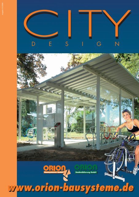
CITY<br />
D E S I G N<br />
Stadtmöblierung GmbH<br />
www.orion-bausysteme.de
ORION Bausysteme<br />
Kreative Produkte für Kommunen,<br />
Industrie, Handwerk und Handel.<br />
ORION - Bausysteme aus Deutschland.<br />
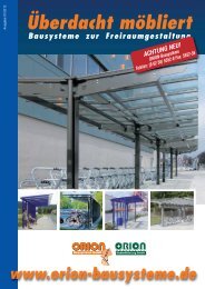
• <strong>Fahrradparker</strong> • Stadtmobiliar • Überdachungssysteme<br />
• Schallgedämmte Kabinen • Rohr- und Profilbiegetechnik<br />
Creative products for municipalities,<br />
industry, trades and commerce.<br />
ORION - Bausysteme from Germany.<br />
• <strong>Bicycle</strong> <strong>Stand</strong>s • Public Facilities • Shelter Systems<br />
• Acoustic Dampened Cabins • Tube and Profile Bending Engineering<br />
Des produits créatifs <strong>pour</strong> les communes,<br />
les industries, les artisans et les commerçants.<br />
ORION – Système de construction venant d’Allemagne.<br />
• <strong>Support</strong>s <strong>pour</strong> <strong>bicyclette</strong>s • Mobilier urbain • Système de toiture<br />
• Cabines insonorisées •Technique de cintrage de profilés et de tubes<br />
2
ALPHA <strong>Fahrradparker</strong>, <strong>Bicycle</strong> <strong>Stand</strong>, <strong>Support</strong> <strong>pour</strong> <strong>bicyclette</strong><br />
• Integriertes Schließsystem<br />
• <strong>Stand</strong>sicherheit des Fahrrades<br />
• Diebstahlschutz<br />
• eindeutige Funktion<br />
• minimaler Platzbedarf<br />
• ansprechendes Design<br />
Der <strong>Fahrradparker</strong> ALPHA ist mit einem Schließsystem ausgestattet,<br />
womit das Fahrrad im oberen Rahmendreieck gesichert wird. Die<br />
Rahmensicherung erfolgt über einen Schließbolzen, der mit einem<br />
handelsüblichen Vorhängeschloß arretiert wird. Durch die<br />
Anordnung des Vorhängeschlosses innerhalb des Schließsystems ist<br />
ein Zerstören mittels Bolzenschneider etc. nahezu unmöglich.<br />
Grundsätzlich können Fahrräder an den stabilen Anlehnbügel auch<br />
mit jedem handelsüblichen Bügel- oder Seilschloß angeschlossen<br />
werden. <strong>Fahrradparker</strong> ALPHA sind als Einzelparker, Doppelparker<br />
oder Reihenanlagen lieferbar. Beim ALPHA-Doppelparker sind die<br />
Fahrräder entgegengesetzt und parallel eingeparkt. Bei der<br />
ALPHA-Reihenanlage stehen die Fahrräder mit einem Winkelversatz schräg hintereinander, wodurch der benötigte Verkehrsraum äußerst<br />
gering gehalten werden kann und durch diese Anordnung das Rohrsystem der Reihenanlage gleichzeitig als Absperrsystem zum fließenden<br />
Verkehr, auf öffentlichen Plätzen aber auch auf breiten Bürgersteigen nutzbar ist.<br />
• integrated lock system<br />
• stability for the bicycle<br />
• antitheft protection<br />
• clear functionality<br />
• minimum space requirements<br />
• appealing design<br />
The ALPHA bicycle stand is equipped with a lock system so that the bicycle can be secured by its upper frame triangle. The frame lock is<br />
accomplished with a slide bolt that can be secured in position with a conventional padlock. Because of the padlock's position within the<br />
lock system it is virtually impossible to destroy the padlock with bolt-cutters etc. Of course it is also essentially possible to secure a bicycle to<br />
this stand's sturdy brace-frame with a conventional U-bar lock or cable lock. The ALPHA bicycle stand is available as single stands, double<br />
stands or row systems. <strong>Bicycle</strong>s are parked in parallel but opposing directions with the ALPHA double stand. <strong>Bicycle</strong>s are arranged at an<br />
slanted offset angle behind one another in ALPHA row systems. This keeps required traffic space to an absolute minimum and this arrangement<br />
also serves as a barricade to order the flow of traffic, an attribute which can be quite useful in open public areas or on wide sidewalks.<br />
• Système de verrouillage intégré<br />
• Stabilité au renversement de la <strong>bicyclette</strong><br />
• Protection antivol<br />
• Fonctionnement intuitif<br />
• Occupation d'espace réduite<br />
• Design attractif<br />
Le parking <strong>pour</strong> <strong>bicyclette</strong> ALPHA est équipé d'un système antivol permettant de verrouiller les vélos au niveau du triangle supérieur du<br />
cadre. Il s'agit d'un boulon de fermeture qui sera arrimé par un cadenas courant. Les cadenas sont orientés dans le système de verrouillage<br />
de telle manière qu'il est pratiquement impossible de les détruire par ex. avec une cisaille à boulon ou autre engin. Les <strong>bicyclette</strong>s peuvent<br />
également être sécurisées aux arceaux du parking avec n'importe quel antivol en U ou "boa". Le modèle ALPHA est disponible comme parking<br />
simble, double ou en rangée. Dans le parking double ALPHA les vélos sont garés en tête-bêche. Dans le parking en rangée ALPHA,<br />
ils sont placés en biais côte à côté avec un décalage angulaire permettant ainsi de réduire considérablement l'espace d'accès. La disposition<br />
des tubes en rangée permet en même temps d'utiliser le parking <strong>pour</strong> bloquer le trafic et de le placer sur des trottoirs larges.<br />
4
ALPHA-Einzelparker<br />
ALPHA-single sided<br />
ALPHA-à un côté<br />
ALPHA-Doppelparker<br />
ALPHA-double sided<br />
ALPHA-bilatéral<br />
ALPHA-Reihenanlage einseitig<br />
ALPHA-row system single sided<br />
ALPHA-en rangèe à un côté<br />
ALPHA-Reihenanlage doppelseitig<br />
ALPHA-row system double sided<br />
ALPHA-en rangèe bilatéral<br />
ALPHA<br />
Bezeichnung Einzelparker Einzelparker Doppelparker Doppelparker<br />
single-sided single-sided double-sided double-sided<br />
à un côté à un côté bilatéral bilatéral<br />
einbetonieren aufschrauben einbetonieren aufschrauben<br />
concrete set bolt mounted concrete set bolt mounted<br />
bétonner boulonner bétonner boulonner<br />
Stahl steel, hot Acier # 360000 # 360010 # 360020 # 360030<br />
feuerverzinkt galvanised galvanisé<br />
wie vor & powder +revêtement par # 360040 # 360050 # 360060 # 360070<br />
+pulverbeschichtet coated<br />
pulvérisation<br />
de peinture<br />
Edelstahl natural Inox # 360160 # 360190 # 360220 # 360250<br />
natur stainless steel nature<br />
Edelstahl pickled Inox # 360170 # 360200 # 360230 # 360260<br />
gebeizt stainless steel décapé<br />
Edelstahl electropolished Inox # 360180 # 360210 # 360240 # 360270<br />
elektropoliert stainless steel électropoli<br />
5
BETA-Collection<br />
<strong>Fahrradparker</strong>, <strong>Bicycle</strong> <strong>Stand</strong>,<br />
<strong>Support</strong> <strong>pour</strong> <strong>bicyclette</strong><br />
2<br />
3<br />
1<br />
4<br />
5<br />
Auch als BETA-BASIS auf Seite 12.<br />
Also as BETA-BASIS on page 12.<br />
Egalement comme BETA-BASIS page 12.<br />
10<br />
9<br />
8<br />
7<br />
BETA-Classico<br />
6<br />
Prüfbericht-Nr.:<br />
M 9610986-08<br />
1 Stabiler Hauptbügel zum gleichzeitigen<br />
Anschließen von Vorderrad und<br />
Rahmen<br />
2 Hocheinstellung<br />
3 Tiefeinstellung<br />
4 Lackschoner am Hauptbügel schützen<br />
vor Kratzern<br />
5 Oberer Bügel bringt Ordnung in<br />
die Radeinstellung<br />
6 Unterer Bügel ermöglicht<br />
Hocheinstellung des Rades<br />
7 Durch verschieden lange Distanzrohre<br />
(Bodenrahmen) sind variable<br />
Radabstände (Achsabstände) möglich.<br />
8 Rohrverbinder aus Temperguß<br />
garantiert kraftschlüssige Verbindung<br />
im Baukastensystem<br />
9 Durch die FOCUSsiereinrichtung<br />
lehnt das Rad stets felgenschonend<br />
am Hauptbügel an<br />
10 Gerade Endrohre erleichtern die<br />
Reinigung der Stellfläche durch offenen<br />
Bodenrahmen<br />
1 sturdy main-bar to which both front<br />
wheel and bike frame can be locked<br />
2 high position<br />
3 low position<br />
4 scratch guard on the main-bar to<br />
prevent scratches<br />
5 upper bar ensures proper wheel<br />
positioning<br />
6 lower bar makes high position parking<br />
possible<br />
7 various length options for the spacing<br />
tube (ground frame) permit differing<br />
bicycle spacing (axis spacing)<br />
8 tube connectors made of malleable<br />
cast iron guarantee powerful<br />
connections for the modular system<br />
9 the FOCUS fixture ensures that the<br />
bicycle always leans on the main-bar<br />
while still being gentle to the fender<br />
10 straight end-tubes simplify parking<br />
area cleaning by avoiding a closedend<br />
design<br />
1 Arceau principal stable permettant<br />
de cadenasser en même temps<br />
la roue avant et le cadre<br />
2 Position haute<br />
3 Position basse<br />
4 Des plaquettes caoutchoutées<br />
placées sur l'arceau principal protègent<br />
la peinture contre les éraflures<br />
5 L’arceau supérieur maintient la<br />
roue correctement en place<br />
6 L’arceau inférieur soutient le<br />
vélo placé en position haute<br />
7 A l'aide de tube d'écartement<br />
de différentes longueurs (cadre au<br />
sol) il est possible de varier les<br />
distances entre les vélos (entre-axe) .<br />
8 Des tubes de raccord en fonte<br />
malléable garantissent un raccordement<br />
solide dans le système de construction<br />
9 Grâce au dispositif Focus, le vélo est<br />
toujours appuyé à l’arceau sans que<br />
la jante soit endommagée<br />
10 Le nettoyage des surfaces est facilité<br />
par des cadres en tubes droits sans<br />
retours.<br />
6
Daten und Fakten<br />
• Konzeption:<br />
•• Modulbauweise. Radparker läßt<br />
sich im Baukastensystem konfektionieren.<br />
• Material:<br />
•• Stahl (feuerverzinkt); und auf<br />
Wunsch zusätzlich pulverbeschichtet<br />
im Farbton nach RAL.<br />
•• Edelstahl gebeizt oder elektropoliert<br />
• Radeinstellung:<br />
•• Tiefeinstellung oder Hoch-<br />
/Tiefeinstellung<br />
•• Einzel- und Doppelparker, sowie als<br />
Reihenanlage in beliebiger Länge<br />
• Befestigung:<br />
•• Einbetonieren<br />
•• Aufschrauben<br />
•• Beschwerung durch Beton-Poller<br />
• Zertifikate<br />
•• ADFC geprüft, TÜV geprüft (Typ<br />
BETA BT-Focus, 800 mm Achse,<br />
doppelseitige Radeinstellung, Tief,<br />
Prüfbericht-Nr. M9610986-08 und<br />
BETA XXL, hoch/tief, TR6102-0101)<br />
Data and Facts<br />
• Concept:<br />
•• modular construction, bicycle stand<br />
can be assembled as a kit that fits<br />
the given application<br />
• Material:<br />
•• steel (hot galvanised); on request<br />
also powder coated in RAL colours<br />
•• pickled or electropolished stainless<br />
steel<br />
• Parking Positions:<br />
•• low or high positions / low positions<br />
only<br />
•• single or double sided stands, row<br />
units in any length<br />
• Mounting:<br />
•• concrete set<br />
•• bolt mounted<br />
•• weighted down with concrete<br />
bollards<br />
• Certification:<br />
•• ADFC tested, TÜV tested (type BETA<br />
BT-FOCUS, 800 mm axes, doublesided<br />
stand, low positions only, test<br />
report no. M9610986-08 and<br />
BETA XXL, high/low, TR6102-0101)<br />
Données et explications<br />
• Conception<br />
•• Construction modulaire. Le support <strong>pour</strong><br />
<strong>bicyclette</strong> se laisse assembler par système<br />
modulaire.<br />
• Matériel:<br />
•• Acier (galvanisé); et sur demande revêtement<br />
par peinture pulvérisée dans les<br />
coloris RAL.<br />
•• Inox décapé ou électropoli<br />
• Position du vélo<br />
•• Position basse ou haute / basse<br />
•• <strong>Support</strong> <strong>pour</strong> <strong>bicyclette</strong> simple ou<br />
double, ainsi qu'en rangée de longueur<br />
indéfinie<br />
• Fixation:<br />
•• Encastrer dans du béton<br />
•• Boulonner<br />
•• Lester par des plots en béton<br />
• Certifications<br />
•• Certification par le Club général de la<br />
<strong>Bicycle</strong>tte (ADFC Allemagne) (Type BETA<br />
BT-Focus, axe 800 mm, support bilatéral,<br />
position basse, certificat nº M9610986-08.<br />
BETA XXL, support basse ou haute/basse,<br />
certificat nº TR6102-0101)<br />
BETA-Mini BETA-Safe BETA-BASIS BETA-Plakativ BETA-Poller<br />
BETA-XXL<br />
3<br />
2<br />
4<br />
NEU<br />
NEW<br />
NOUVEAU<br />
1<br />
5<br />
6<br />
10<br />
9<br />
7<br />
8<br />
ADFC Prüf-Nr.:<br />
Q 0701<br />
7
BETA-Collection<br />
<strong>Fahrradparker</strong>, <strong>Bicycle</strong> <strong>Stand</strong>, <strong>Support</strong><br />
<strong>pour</strong> <strong>bicyclette</strong><br />
8
Bestell-Code<br />
Der <strong>Fahrradparker</strong> BETA-XXL stellt für (fast)<br />
jede Problemstellung die perfekte Lösung<br />
dar. Insbesondere die Variabilität in der<br />
Anwendung zeugt daher von seiner<br />
Klasse. Reduziert man diese Vielfalt auf<br />
diejenigen mit täglicher, praktischer<br />
Relevanz, dann sprechen wir immerhin von<br />
192 Varianten. Den Überblick zu<br />
behalten ist dennoch ganz einfach.<br />
Ihre Wahl treffen Sie, indem Sie aus den<br />
farblich hinterlegten Feldern jeweils einen<br />
Kennbuchstaben je Feld auswählen. Die<br />
Zuordnung der einzelnen Kennbuchstaben<br />
in den Bestell-Code ergibt sich nach den<br />
Farben (es kann jeweils nur 1 Kennbuchstabe<br />
je Farbfeld ausgewählt werden). Der<br />
ermittelte Bestell-Code beschreibt die von<br />
Ihnen gewählte Variante bis ins Detail.<br />
Order Code<br />
The BETA-XXL bicycle stand is the perfect<br />
solution for (almost) any problem situation.<br />
Its application versatility is particularly indicative<br />
of its classic design. Even when one<br />
reduces the number of variations to those<br />
which have daily practical relevance,<br />
there are still 192 variations.<br />
Nonetheless it is still easy to<br />
retain an overview.<br />
You simply make your selection by picking<br />
one code letter from each of the colour<br />
coded fields. The order code is formed by<br />
picking individual code letters from the<br />
coloured fields (only one code letter per<br />
colour field may be chosen). This order<br />
code then becomes a detailed description<br />
of the variation of your choice.<br />
Codes de commande<br />
Le support <strong>pour</strong> <strong>bicyclette</strong> BETA-XXL représente<br />
<strong>pour</strong> (presque) tous les problèmes la<br />
solution idéale. La variété de ses utilisations<br />
en de ‘montre la classe. Rien qu'en<br />
réduisant ses possibilités à celles utilisées<br />
au quotidien on arrive à 192 variantes.<br />
Il est toutefois très facile de<br />
ne pas s'y perdre.<br />
Vous faites votre choix en sélectionnant une<br />
lettre d'identification par ligne colorée. La<br />
correspondance de chaque lettre d'identification<br />
avec la référence de commande se<br />
fait d'après les couleurs (il n'est possible de<br />
sélectionner qu’une lettre par zone en couleur).<br />
Le code de commande ainsi déterminé<br />
vous décrira la variante que vous avez<br />
choisie jusque dans le moindre détail.<br />
Bestell-Code / order code / code de commande<br />
30<br />
Typ Stahl Edelstahl Beschickung FOCUS Radeinstellung Befestigung<br />
Steel Acier stainless steel Inox Version Version Parking Position Position du vélo Mounting Fixation<br />
Tief<br />
Tief/Hoch<br />
BETA<br />
Low Basse<br />
High/low Basse/haute<br />
feuerverzinkt feuerverzinkt gebeizt elektropoliert einseitig doppelseitig ja nein Radabstand in mm aufschrauben einbetonieren<br />
+ pulverbeschichtet 600 700 800 360 400 500<br />
BETA hot galvanised hot galvanised pickled electropolished single-sided double-sided yes no wheel spacing in mm bolt mounted concrete set<br />
& powder coated 600 700 800 360 400 500<br />
BETA galvanisé galvanisé décapé électropolissé à un côté bilatéral oui non Distance des vélos en mm boulonner bétonner<br />
+ revêtement par 600 700 800 360 400 500<br />
pulvérisation<br />
de peinture<br />
30 A B C D E F G H I X J K L Y M N<br />
Und so könnte Ihre Bestellung aussehen: 120 Stück Radeinstellungen, Bestell-Code: 30 B F G L M<br />
And here is how your order might look: park positions, 120 each, order code: 30 B F G L M<br />
Votre commande <strong>pour</strong>rait alors se présenter de la façon suivante : 120 emplacements de vélos, code de commande : 30 B F G L M<br />
9
BETA-Technik<br />
<strong>Fahrradparker</strong>, <strong>Bicycle</strong> <strong>Stand</strong>, <strong>Support</strong> <strong>pour</strong> <strong>bicyclette</strong><br />
BETA-Poller<br />
BETA-Montage / Assembly / Montage<br />
A<br />
B<br />
BETA-Light, mit fluoreszierender<br />
Beschichtung<br />
BETA-Light with fluorescent<br />
coating<br />
BETA Light avec revêtement<br />
fluorescent<br />
*<br />
kg<br />
10<br />
* Befestigungselemente zur Bodenverankerung nicht im Lieferumfang enthalten! / The fastening elements for surface anchoring are not included! / Eléments de fixation <strong>pour</strong> ancrage au sol non compris dans la livraison !
BETA-Basis<br />
<strong>Fahrradparker</strong>, <strong>Bicycle</strong> <strong>Stand</strong>, <strong>Support</strong> <strong>pour</strong> <strong>bicyclette</strong><br />
Modell CLASSICO<br />
Der Parker Beta-Basis stellt die Reduktion<br />
der High-End-Version des Beta auf seinen<br />
Ursprung dar: den klassischen Anlehnbügel.<br />
Modulbauweise und die Wahl zwischen<br />
verschiedenen Radabständen bleiben<br />
erhalten. Dadurch ist der Beta-Basis dem<br />
klassischen Anlehnbügel weit überlegen.<br />
Das gilt auch bei den Kosten. Im direkten<br />
Vergleich mit Anlehnbügeln oder den billigen<br />
Felgenklemmen besticht der Beta-<br />
Basis. Und dies nicht zuletzt durch die<br />
Tatsache, daß der BETA-Basis durch seinen<br />
Bodenrahmen - anders als klassische<br />
Anlehnbügel - keine Fundamente benötigt,<br />
sondern “frei” aufgestellt werden kann.<br />
Perfektioniert wird der BETA-Basis durch<br />
den Einsatz des Focuselementes (Option).<br />
Dadurch lehnt das Rad stets am<br />
Hauptbügel an.<br />
Der BETA-Basis kann grundsätzlich als<br />
Doppelparker, also mit beidseitiger Beschickung<br />
eingesetzt werden.<br />
The BETA-BASIS bicycle stand represents<br />
the high-end BETA version's return to its<br />
origin; the classic brace frame.<br />
Its modular construction and the various<br />
bike spacing options remain intact. Thus<br />
the BETA-BASIS is entirely superior to the<br />
classic brace frame. This applies also to<br />
cost. BETA-BASIS stands out even in direct<br />
comparison to other brace frames or<br />
cheap rim-clamp type stands. And this is<br />
at least in part due to the fact that - in<br />
contrast to classic brace frames - BETA-<br />
BASIC's ground frame requires no foundation<br />
– so it can be set up entirely "freestanding".<br />
The BETA-BASIS can also be<br />
optimised with focus elements (option).<br />
This ensures that the bike always rests on<br />
the main brace.<br />
BETA-BASIS is available as a double<br />
stand too, i.e. it can be ordered in a configuration<br />
for use from both sides.<br />
Modell CLASSICO + Focus<br />
Le parking BETA-BASIS est la réduction de<br />
la version sophistiquée BETA a sa plus<br />
simple expression : l’arceau classique.<br />
La construction modulable et le choix des<br />
différentes distances entre les vélos sont<br />
bien entendu conservés, ce qui permet au<br />
BETA-BASIS de prendre la tête dans le<br />
rang des arceaux classiques. Son prix<br />
étant lui aussi un argument de choix.<br />
Comparé directement aux autres arceaux<br />
et « écraseurs de jantes », le BETA-BASIS<br />
ne se distingue pas moins par son cadre<br />
d’assise qui rend toute fondation superflue<br />
et permet ainsi de le poser « librement »<br />
sur le sol. La perfection est atteinte grâce<br />
aux éléments de focalisation (en option)<br />
qui forcent le vélo à rester appuyé contre<br />
l'arceau.<br />
Le BETA-BASIS est disponible en version<br />
double, c’est-à-dire que les vélos peuvent<br />
être placés de chaque côté.<br />
Modell XXL<br />
Modell CARO<br />
12
Den BETA-BASIS gibt es in folgenden Varianten:<br />
BETA-Basis is available in the following variations:<br />
Le BETA-Basis est disponible dans les modèles suivants :<br />
Typ Stahl Beschickung FOCUS Radeinstellung Befestigung<br />
Steel Acier Version Version Parking Position Position du vélo Mounting Fixation<br />
Tief<br />
Low Basse<br />
feuerverzinkt doppelseitig ja nein Radabstand in mm aufschrauben<br />
hot galvanised double-sided yes no wheel spacing in mm bolt mounted<br />
BETA-Basis galvanisé bilatéral oui non Distance des vélos en mm boulonner<br />
CLASSICO 600 700 800<br />
27 A F G H I X J M<br />
BETA-Basis<br />
XXL<br />
28 A F G H I X J M<br />
BETA-Basis<br />
CARO<br />
29 A F G H I X J M<br />
13
BETA - Project´s<br />
14
Vorher, before, avant ....<br />
Nachher, after, aprés....<br />
15
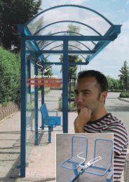
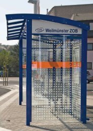
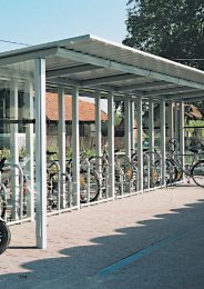
<strong>SIGMA</strong> <strong>Fahrradparker</strong>, <strong>Bicycle</strong> <strong>Stand</strong>, <strong>Support</strong> <strong>pour</strong> <strong>bicyclette</strong><br />
<strong>SIGMA</strong><br />
available as a double stand with bike<br />
parking on both sides as well as a single<br />
stand. This stand's brace-frame design<br />
allows a bicycle to be optimally secured<br />
to the stand with a cable lock at both the<br />
bike's front wheel area as well as the<br />
bike's frame.<br />
<strong>SIGMA</strong><br />
aussi bien en parking double, <strong>pour</strong> placer<br />
un vélo de chaque côté, qu'en parking<br />
simple. Grâce à la disposition de l'arceau<br />
il est possible de protéger le vélo<br />
par un antivol "boa" aussi bien au niveau<br />
de la roue avant que du cadre.<br />
<strong>SIGMA</strong><br />
sowohl als Doppelparker für beidseitige<br />
Radeinstellung, als auch als Einzelparker.<br />
Durch die Gestaltung als Anlehnbügel<br />
kann das Fahrrad sowohl im Bereich des<br />
Vorderrades als auch mit dem<br />
Fahrradrahmen mittels Seilschloß optimal<br />
gesichert werden.<br />
16
<strong>SIGMA</strong><br />
Einzelparker Einzelparker Doppelparker Doppelparker<br />
single-sided single-sided double-sided double-sided<br />
à un côté à un côté bilatéral bilatéral<br />
einbetonieren aufschrauben einbetonieren aufschrauben<br />
concrete set bolt mounted concrete set bolt mounted<br />
bétonner boulonner bétonner boulonner<br />
Stahl steel, hot Acier # 350000 # 350010 # 350020 # 350030<br />
feuerverzinkt galvanised galvanisé<br />
wie vor & powder +revêtement par # 350040 # 350050 # 350060 # 350070<br />
+pulverbeschichtet coated<br />
pulvérisation<br />
de peinture<br />
Edelstahl natural Inox # 350080 # 350110 # 350140 # 350170<br />
natur stainless steel nature<br />
Edelstahl pickled Inox # 350090 # 350120 # 350150 # 350180<br />
gebeizt stainless steel décapé<br />
Edelstahl electropolished Inox # 350100 # 350130 # 350160 # 350190<br />
elektropoliert stainless steel électropoli<br />
17
OMEGA <strong>Fahrradparker</strong>, <strong>Bicycle</strong> <strong>Stand</strong>, <strong>Support</strong> <strong>pour</strong> <strong>bicyclette</strong><br />
Das Bike Rack OMEGA verkörpert in idealer<br />
Weise das optimale Mix aus Design<br />
und Funktion. Rundherum rund bis in alle<br />
Details, um Verletzungsrisiken zu minimieren;<br />
und deshalb der geeignete Radparker<br />
für Biker aller Altersklassen. Das Einstellen<br />
des Rades ist kinderleicht - vom Kinderrad<br />
bis hin zum Mountain-Bike - 5 an der Zahl<br />
können im OMEGA bei beidseitiger<br />
Nutzung geparkt werden.<br />
The OMEGA bike rack ideally embodies<br />
the optimal mix of design and function.<br />
Round about, it is round right down to its<br />
smallest detail. This minimises the risk of<br />
injury and makes it an ideal bicycle stand<br />
for bikers of all ages. Parking a bike in it is<br />
child's play - from children's bikes to mountain<br />
bikes - up to 5 at a time can be parked in<br />
an OMEGA when it is used on both sides..<br />
Le support <strong>pour</strong> <strong>bicyclette</strong> OMEGA allie<br />
de façon idéale le design à la fonctionnalité.<br />
Et ceci jusque dans les moindres<br />
détails afin de minimiser le plus possible<br />
tous risques de blessures ;<br />
il peut donc ainsi être utilisé par les<br />
cyclistes de tous âges. Placer le vélo est<br />
un jeu d'enfant – du VTT au vélo <strong>pour</strong><br />
enfant – il est possible d’en placer 5 sur<br />
le support OMEGA deux faces.<br />
18
OMEGA<br />
einbetonieren<br />
concrete set<br />
bétonner<br />
aufschrauben<br />
bolt mounted<br />
boulonner<br />
Stahl steel, hot Acier # 320000 # 320010<br />
feuerverzinkt galvanised galvanisé<br />
Aluminium natural Aluminium # 321000 # 321010<br />
natur aluminium nature<br />
Aluminium colour coated Aluminium # 322000 # 322010<br />
farbbeschichtet aluminium peint<br />
Aluminium rainbow Aluminium # 323000 # 323010<br />
regenbogen aluminium arc-en-ciel<br />
Edelstahl natural Inox # 324000 # 324010<br />
natur stainless steel nature<br />
Edelstahl pickled Inox # 325000 # 325010<br />
gebeizt stainless steel décapé<br />
Edelstahl electropolished Inox # 326000 # 326010<br />
elektropoliert stainless steel électropoli<br />
19
INOX <strong>Fahrradparker</strong>, <strong>Bicycle</strong> <strong>Stand</strong>, <strong>Support</strong> <strong>pour</strong> <strong>bicyclette</strong><br />
ALPHA<br />
BETA<br />
Bei der Auswahl der Werkstoffe<br />
und deren Dimensionierungen<br />
setzen wir auf Qualität: Edelstahl,<br />
WStNr.: 1.4301, auf Wunsch<br />
oberflächenbehandelt, z.B.<br />
gebeizt oder zusätzlich elektropoliert.<br />
Rohrdurchmesser 48,3 mm<br />
20
<strong>SIGMA</strong><br />
OMEGA<br />
We believe in quality when it comes to a choice of<br />
materials and their dimensions: stainless steel,<br />
Mat. No.: 1.4301 (on request with extra surface<br />
treatments, e.g. pickled or additionally electropolished).<br />
Tube diameter, 48.3 mm<br />
Nous misons sur la qualité <strong>pour</strong> le choix des<br />
matériaux et de leur dimensionnement : l'Inox<br />
Réf. 1.4301, au choix surface traitée, par ex.<br />
bruni ou en plus électropoli. Diamètre de tube 48,3 mm<br />
21
PSI <strong>Fahrradparker</strong>, <strong>Bicycle</strong> <strong>Stand</strong>, <strong>Support</strong> <strong>pour</strong> <strong>bicyclette</strong><br />
• Fahrradparkpoller für einseitige oder<br />
doppelseitige Radeinstellung, passend<br />
für alle gängigen Fahrradtypen,<br />
• kippsicher<br />
• diebstahlsicheres Anschließen von<br />
Vorderrad und Rahmen mit Seil- oder<br />
Bügelschloß,<br />
• robust in Bezug auf Vandalismus.<br />
Säule Ø ca. 76 mm, Höhe ca.<br />
880mm, Fahrradhalter aus Rundrohr Ø<br />
ca. 17,2 mm / Rundstahl Ø ca. 16 mm.<br />
Zu empfehlender Radabstand: 600 mm.<br />
Merkmale:<br />
• Besonders großer Reinigungsabstand<br />
zwischen OKFFB und UK Fahrradhalter<br />
von ca. 260 mm.<br />
• Weiterentwicklung des <strong>Fahrradparker</strong>s<br />
GAMMA, der gemeinsam mit der DB<br />
AG für die Fahrradmitnahme in<br />
InterRegio-Zugabteilen konzipiert wurde.<br />
• Alle Bauteile mit großen Radien, ohne<br />
scharfe Kanten ausgeführt.<br />
• Kein Felgenquetscher, <strong>Stand</strong>sicherheit<br />
des Rades durch Anlehnen. Die mit<br />
der Felge in Berührung kommende<br />
Kontaktstelle des <strong>Fahrradparker</strong>s ist zur<br />
schonenden Behandlung der Fahrräder<br />
mit einem Schrumpfschlauch überzogen.<br />
• Hoch-/tief - Anordnung möglich,<br />
dadurch kann der Radabstand auf ca.<br />
400 mm reduziert werden.<br />
• Alternative Ausführungen: Säule in der<br />
Ausbildung wie Poller „Mannheim“<br />
oder „Frankfurt“ möglich; kundenspezifische<br />
Modifikationen auf Anfrage.<br />
• Bike stand bollards for single-sided or<br />
double-sided parking; suitable for all<br />
common bicycle types<br />
• tip secure<br />
• theft-secure locking options for the front<br />
wheel and frame with cable or U-bar<br />
lock,<br />
• robust with respect to vandalism.Post Ø<br />
about 76 mm, height about 880 mm,<br />
bike bracket made of tube steel Ø<br />
about 17.2 mm / tube steel Ø about<br />
16 mm. Recommended park spacing:<br />
600 mm.<br />
Features:<br />
• The large space between the paving<br />
surface and the lower edge of the bike<br />
bracket (about 260 mm) makes pavement<br />
sweeping/cleaning easy.<br />
• Advanced development of the<br />
GAMMA bicycle stand, originally a<br />
joint-development with German rail for<br />
bicycle stowage in passenger areas of<br />
inter-regional train cars.<br />
• All components have large radius and<br />
there are no sharp edges.<br />
• No fender pinchers, the wheel is leaned<br />
securely against the brace.<br />
Contact points between the rim and the<br />
stand are sleeved with heatshrink for<br />
gentle handling of the bicycle.<br />
• High/low configurations available<br />
which allow parked spacing to be<br />
reduced to about 400 mm.<br />
• Alternate designs: bollard posts in styles<br />
like "Mannheim" or "Frankfurt" are possible;<br />
customer-specific modifications on<br />
request.<br />
• Borne de parking <strong>pour</strong> un ou deux<br />
vélos de tous types,<br />
• stable<br />
• protection optimale par antivol en U ou<br />
"boa" à la roue avant et au cadre,<br />
• robustesse résistant au vandalisme<br />
Colonne Ø env. 76 mm, hauteur env.<br />
880mm, fixe vélo en tube rond Ø env.<br />
17,2 mm / acier rond Ø env. 16 mm.<br />
Ecart recommandé entre les vélos :<br />
600 mm.<br />
Caractéristiques :<br />
• Distance d'env. 260 mm entre le sol et<br />
le fixe-vélo <strong>pour</strong> nettoyage facile de la<br />
voirie.<br />
• Conception retravaillée du parking<br />
GAMMA en collaboration avec la<br />
Bundes Bahn AG (Société allemande<br />
des chemins de fer) <strong>pour</strong> permettre l'embarquement<br />
de vélos dans les compartiments<br />
des trains interrégionaux.<br />
• Tous les éléments ont un grand rayon et<br />
aucune arête vive.<br />
• Ce n'est pas un "écraseur de jante", le<br />
vélo est stabilisé en l'appuyant contre<br />
la borne. Le point de contact de la<br />
borne avec la jante est recouvert d'une<br />
gaine thermorétractable <strong>pour</strong> protéger<br />
le vélo.<br />
• Agencement en haut/en bas qui permet<br />
de réduire l'écart entre les vélos à<br />
env. 400 mm.<br />
• Autres versions : Colonnes en version<br />
"Mannheim" ou "Frankfurt" possible,<br />
modifications spécifiques sur demande.<br />
22
Gestaltungselemente Abschlußhauben<br />
– ohne Aufpreis –<br />
Design elements and top caps<br />
– at no extra charge –<br />
Accessoires esthétiques<br />
- sans supplément -<br />
Fluoreszierende Pulverbeschichtung als<br />
Option. Selbst in dunkelsten Ecken gut<br />
zu sehen!<br />
Optional fluorescent powder coating.<br />
Easy to see even in the darkest of corners!<br />
En option, revêtement fluorescent. Visible<br />
même dans les coins les plus sombres !<br />
Typ FRANKFURT für Pollersäule aus<br />
Quadratrohr.<br />
Type FRANKFURT bollard posts of square<br />
tubing.<br />
Type FRANKFURT <strong>pour</strong> colonne en tube carré.<br />
Typ Mannheim für Pollersäule aus Rundrohr.<br />
Type MANNHEIM bollard posts of round<br />
tubing.<br />
Type MANNHEIM <strong>pour</strong> colonne en tube rond.<br />
P S I<br />
Einzelparker Einzelparker Doppelparker Doppelparker<br />
single-sided single-sided double-sided double-sided<br />
à un côté à un côté bilatéral bilatéral<br />
einbetonieren aufschrauben einbetonieren aufschrauben<br />
concrete set bolt mounted concrete set bolt mounted<br />
bétonner boulonner bétonner boulonner<br />
Stahl steel, hot Acier # 410000 # 410600 # 410100 # 410800<br />
feuerverzinkt galvanised galvanisé<br />
wie vor & powder +revêtement par # 410099 # 410699 # 410199 # 410899<br />
+pulverbeschichtet coated<br />
pulvérisation<br />
de peinture<br />
Edelstahl pickled Inox # 410200 # 410700 # 410300 # 410900<br />
gebeizt stainless steel décapé<br />
Edelstahl electropolished Inox # 410400 # 410705 # 410500 # 410905<br />
elektropoliert stainless steel électropoli<br />
23
Absperr- und Anlehnbügel<br />
Barricade Frames, Arceau de verrouillage<br />
Type D<br />
Ø 48,3 Ø 60,3<br />
Type Berlin<br />
Type Berlin ø # # #<br />
42,4 506091 506092 506093<br />
48,3 506094 506095 506096<br />
60,3 506097 506098 506099<br />
Type London<br />
40x40<br />
# 506083<br />
# 506084<br />
# 506085<br />
Type Paris<br />
60x12<br />
# 506086<br />
# 506087<br />
# 506088<br />
Type London<br />
Type Paris<br />
24
Bodenhülse<br />
aus Grauguß mit<br />
Klemmring zur einfachen Montage<br />
und Demontage von Rundrohren<br />
Ø 48,3 mm Best.-Nr. 300500<br />
Deckel Best.-Nr. 300501<br />
Ø 60,3 mm Best.-Nr. 300510<br />
Deckel Best.-Nr. 300511<br />
Ground Dowel Casings<br />
of cast iron with clamp ring for the<br />
simple assembly and disassembly of<br />
round tubing<br />
Ø 48.3 mm # 300500<br />
cover # 300501<br />
Ø 60.3 mm # 300510<br />
cover # 300511<br />
Manchon<br />
en fonte grise avec bague de serrage<br />
<strong>pour</strong> un montage et démontage simple<br />
des tubes ronds<br />
Ø 48,3 mm Référence 300500<br />
Capuchon Référence 300501<br />
Ø 60,3 mm Référence 300510<br />
Capuchon Référence 300511<br />
Stahl feuerverzinkt<br />
hot galvanised steel<br />
Acier galvanisé à chaud<br />
+ pulverbeschichtet<br />
+ powder coated<br />
+ revêtement de peinture pulvérisée<br />
Edelstahl natur<br />
natural stainless steel<br />
Ynox nature<br />
Edelstahl gebeitzt<br />
pickled stainless steel<br />
Acier décapé<br />
Ab Losgrößen > 20 Stück Staffelpreise erfragen<br />
for lot sizes > 20 each, enquire about pricing<br />
Prix échelonné sur demande <strong>pour</strong> commande > 20 unités<br />
ABSPERRBÜGEL<br />
Barricade Frames,<br />
Arceau de sécurité<br />
A B C D E F G H<br />
# 506000 # 506010 # 506020 # 506030 # 506040 # 506050 # 506060 # 506070<br />
ø 60,3 ø 48,3<br />
# 506001 # 506011 # 506021 # 506031 # 506041 # 506051 # 506061 # 506071<br />
# 506002 # 506012 # 506022 # 506032 # 506042 # 506052 # 506062 # 506072<br />
# 506003 # 506013 # 506023 # 506033 # 506043 # 506053 # 506063 # 506073<br />
# 506004 # 506014 # 506024 # 506034 # 506044 # 506054 # 506064 # 506074<br />
# 506005 # 506015 # 506025 # 506035 # 506045 # 506055 # 506065 # 506075<br />
Fußplatten: Ausführung der Absperrbügel zum Aufschrauben Best.Nr. 506999 • base plates: barricade frame model for<br />
bolt mounting # 506999 • Plaque au sol ; Version de l’arceau de sécurité à boulonner Référence 506999<br />
25
GAMMA,<br />
<strong>Fahrradparker</strong>, <strong>Bicycle</strong> <strong>Stand</strong>, <strong>Support</strong> <strong>pour</strong> <strong>bicyclette</strong><br />
Der Klassiker unter den „Aufrechten“,<br />
geeignet für alle Radtypen. Eine stabile<br />
Montageplatte ermöglicht die problemlose<br />
Befestigung des <strong>Fahrradparker</strong>s in Zugund<br />
Busabteilen, Transportwagen sowie in<br />
Parkhäusern, Kellerräumen, Garagen oder<br />
Fahrradschuppen. Die mit der Felge in<br />
Berührung kommende Kontaktstelle des<br />
<strong>Fahrradparker</strong>s GAMMA ist zur schonenden<br />
Behandlung der Fahrräder mit einem<br />
Schrumpfschlauch überzogen.<br />
The classic among the "uprights" is well<br />
suited to all types of bicycles. A sturdy<br />
mounting plate ensures a secure hold on<br />
the bicycle in trains and buses as well as<br />
in parking garages, cellar rooms, garages<br />
and in bicycle sheds. GAMMA bicycle<br />
stand surfaces which come into<br />
contact with the fender are covered with<br />
heat-shrink sleeving to protect bicycles<br />
from being scratched.<br />
Le classique parmi les « verticaux »,<br />
adapté <strong>pour</strong> tous les types de vélos. Une<br />
plaque de montage stable permet une<br />
fixation sans problèmes du support <strong>pour</strong><br />
<strong>bicyclette</strong> dans des bus, des wagons de<br />
train, voitures de transport, ainsi que dans<br />
les parkings, caves, garages ou remises.<br />
La surface de contact entre la jante et le<br />
support GAMMA est recouverte d’une<br />
gaine thermorétractable <strong>pour</strong> éviter tout<br />
endommagement.<br />
GAMMA<br />
Oberfläche<br />
Winkelstellung<br />
angle position<br />
Position angulaire<br />
90 0 70 0 schwenkbar<br />
nach rechts zeigend pivoting Pivotant<br />
pointing to the right orienté vers la droite 0 o 45 o 90 o<br />
Stahl steel, hot Acier # 319000 # 317000 # 315000<br />
feuerverzinkt galvanised galvanisé<br />
feuerverzinkt & powder +revêtement par # 319099 # 317099 # 315099<br />
+ pulverbeschichtet coated pulvérisation<br />
nach Wahl in RAL<br />
de peinture<br />
26
WEGA,<br />
LIFT<br />
WEGA<br />
hängend<br />
hanging position suspendu<br />
feuerverzinkt # 330000<br />
steel, hot galvanised<br />
Acier galvanisé<br />
feuerverzinkt + # 330099<br />
pulverbeschichtet im<br />
Farbton nach RAL<br />
& powder coated<br />
+revêtement par<br />
pulvérisation de peinture<br />
WEGA<br />
Der Allrounder mit der Bananengeometrie<br />
The all-rounder with the banana shape<br />
Le polyvalent en forme de banane<br />
Lift<br />
Der Komfortable mit Power. Rad einhängen, am Sattel leicht zurückziehen, Gasfedermechanik löst aus und zieht das Rad in die hängende Position.<br />
Powerful convenience. Hang the bike by its front wheel, pull the bike back slightly to release the gas/spring mechanism; the bike will be<br />
pulled into its hanging position.<br />
Le confortable puissant. Accrocher le vélo, le faire revenir légèrement en arrière en le tenant par la selle, le mécanisme pneumatique se<br />
déclenche et place le vélo dans la bonne position.<br />
# 340000<br />
27
ARETUS Fahrradsafe, Bike Safe, Cabines à vélos<br />
Bike in, door closed,<br />
finished!<br />
Sides made of sturdy, hot galvanised<br />
sheet steel panels (on request also powder<br />
coated to colour of choice). Roofing<br />
made of corrugated sheet steel; modular<br />
structure with a base unit that can be<br />
combined with any number of extension<br />
units and even added onto at a later<br />
time. Locking mechanism: pad locks or<br />
mortise locks.<br />
Placer le vélo,<br />
fermer la porte, voilà !<br />
Parois en cassettes de tôle d’acier galvanisée,<br />
sur demande recouvertes de peinture<br />
pulvérisée dans les coloris choisis par<br />
le client. Revêtement de la toiture en tôle<br />
d’acier à arêtes vives ; montage sous la<br />
forme d’une unité de base pouvant être<br />
combinée à volonté avec un nombre<br />
indéfini de modules, même ultérieurement.<br />
Mécanisme de verrouillage: cadenas,<br />
serrure à pêne.<br />
Rad einstellen,<br />
Tür verschließen, fertig!<br />
Wandverkleidungen aus stabilen, feuerverzinkten<br />
Stahlblechkassetten auf<br />
Wunsch zusätzlich pulverbeschichtet im<br />
Farbton nach Wahl des Auftraggebers.<br />
Dacheindeckung aus mehrfach gekantetem<br />
Stahlblech; modularer Aufbau in Form<br />
einer Grundeinheit, die mit einer beliebigen<br />
Anzahl an Anbauelementen kombiniert<br />
und auch nachträglich erweitert werden<br />
kann. Verriegelungsmechanik:<br />
Vorhangschloss, Einsteckschloss.<br />
ADFC geprüft auf Basis Q 0504<br />
ADFC tested on base of Q 0504<br />
testé par le Club général de la<br />
<strong>Bicycle</strong>tte (ADFC Allemagne)<br />
en base de Q 0504<br />
28
Sonderkonstruktion<br />
Special model<br />
Type spécial<br />
Grundelement<br />
Anbauelement<br />
ARETUS<br />
Base element Elément de base addition element Elément rapporté<br />
Oberfläche desStahlskelettes: mit Vorhangschloss mit Einsteckschloss mit Vorhangschloss mit Einsteckschloss<br />
Surface of the steel skeleton: with padlock with mortise lock with padlock with mortise lock<br />
structure en acier : avec cadenas avec serrure à pêne avec cadenas avec serrure à pêne<br />
feuerverzinkt # 400100 # 400200 # 401100 # 401200<br />
steel, hot galvanised<br />
Acier galvanisé<br />
zusätzlich pulverbeschichtet # 400199 # 400299 # 401199 # 401299<br />
& powder coated<br />
+revêtement par pulvérisation<br />
de peinture<br />
29
Ausschreibungstext<br />
ADFC Prüf-Nr.:<br />
Q 0504<br />
Fahrradbox ARETUS<br />
Pos. Beschreibung Stück Einheitspreis Gesamtpreis<br />
1 Grundelement ........................................................................................................<br />
1<br />
Anzahl Anbauelemente ..........................................................................................<br />
Fahrradbox ARETUS, Abmessung:<br />
Gesamthöhe ca. 1403 mm, Gesamtbreite eines Grundelementes ca. 850 mm, Gesamtbreite eines<br />
Anbauelementes ca. 800 mm, Gesamttiefe ca. 2000 mm, Türmaß ca. 750 x 1150 mm<br />
(Breite x Höhe).<br />
Modularer Aufbau im Baukastensystem durch Konfektionierung von einem Grundelement mit der aus der<br />
Menge der unterzubringenden Räder resultierenden Anzahl an Anbauelementen.<br />
Die Dachkonstruktion besteht aus einem in Form eines längslaufenden Tonnengewölbes mehrfach gekantetem,<br />
feuerverzinkten Stahlblech.<br />
Auftretendes Dachflächenwasser wird in seitlich angeordneten Regenrinnen gesammelt und nach hinten über<br />
Abtropfbleche geregelt abgeführt.<br />
Die Dachkonstruktion schließt stirnseitig mit einem der Kontur angepassten Wölbungsschutz aus Stahlblech ab.<br />
Das tragende Stahlskelett besteht aus Vierkantprofilen, die über spezielle Verbindungselemente miteinander<br />
kraftschlüssig verbunden werden. Das gesamte Stahlskelett sowie die Verbindungselemente werden im<br />
Tauchbad nach DIN EN ISO 1461 feuerverzinkt. Schweißkonstruktionen sind mangels modularem Aufbau<br />
und dem damit verbundenen Nachteil, im Falle von Schäden Einzelteile nicht austauschen zu können,<br />
unzulässig. Oben beschriebenes Steck-Verbinder-System erleichtert die Montage, so daß diese ebenfalls bauseits<br />
durchgeführt werden kann.<br />
Die Seiten- und Rückwände werden beplankt mit speziell gekanteten Stahlblechkassetten. Die Oberfläche der<br />
Blechkassetten wird durch die Arbeitsgänge Feuerverzinkung (beidseitig) und Pulverbeschichtung (nur<br />
Außenseiten) langfristig gegen Korrosion geschützt und erfüllt zudem hohe ästhetische Ansprüche.<br />
Ausführung des Farbtons nach Wahl des Auftraggebers in RAL.<br />
Die Befestigung der Blechkassetten am Stahlgerüst erfolgt mittels Flachrundkopfschrauben, so daß ein Lösen<br />
vom Äußeren der Box auszuschließen ist.<br />
Die Tür besteht aus stabilen, speziell geformten Stahlblechkassetten; Werkstoff und Oberfläche entsprechen<br />
den Rück- und Seitenwänden.<br />
In die Tür wird das Schließsystem integriert.<br />
Der Auftraggeber wählt zwischen: ❏ Einsteckschloß, vorgerichtet zur Aufnahme eines Profilzylinders, oder<br />
❏ Vorhangschloß.<br />
Die Tür wird am Stahlgerüst mittels stabiler Konstruktionsbänder befestigt. Im Bereich der Schlossfalle besteht<br />
eine Überlappung zwischen Türabschluß und den als Traggerüst ausgebildeten Vierkantrohren. Insofern ist ein<br />
Aufhebeln der Box weitgehend auszuschließen.<br />
Im Innenraum der Radbox wird ein Kleiderhaken angebracht.<br />
Das Einparken des Rades erfolgt „geführt“ innerhalb einer mittig am Boden angeordneten Einstellschiene (feuerverzinkt).<br />
Die Aufstellung der Radbox ist vorgesehen auf befestigtem, ebenen Untergrund, vorzugsweise auf einer<br />
Betonplatte.<br />
Der Bodenrahmen ist mehrfach gelocht, so daß ein bauseitiges Verdübeln möglich ist.<br />
2<br />
Beschichtung des Stahlskelettes im Duplex-Verfahren .<br />
Erster Schritt: Feuerverzinkung im Tauchbad nach DIN EN ISO 1461.<br />
Zweiter Schritt: Pulverbeschichtung im RAL-Farbton nach Wahl des Auftraggebers,<br />
Schichtdicke 80 - 120 my.<br />
Farbbeschichtungsaufbau: • Phosphatierschicht<br />
• Spezialprimer auf Wasserbasis<br />
• Pulverbeschichtung mit uv-stabilisiertem Polyesterpulver, eingebrannt bei ca. 240° C.<br />
Fabrikat der Fahrradbox ARETUS: ORION Bausysteme GmbH<br />
Diesen Text können Sie bei uns auf einer Diskette oder per e-mail (info@orion-bausysteme.de) anfordern<br />
oder von unserer Homepage herunterladen! www.orion-bausysteme.de<br />
31
ADFC Prüf-Nr.:<br />
Q 0504<br />
32
ADFC Prüf-Nr.:<br />
Q 0504
Sicherheit im Kollektiv,<br />
Collective security, La sécurité en collectivité<br />
34
Doppelstockradparker<br />
Double-deck <strong>Stand</strong>s, <strong>Support</strong> <strong>pour</strong> <strong>bicyclette</strong>s à deux étages<br />
ADFC geprüft auf Basis Q 0505<br />
ADFC tested on base of Q 0505<br />
testé par le Club général de la<br />
<strong>Bicycle</strong>tte (ADFC Allemagne)<br />
en base de Q 0505<br />
Einseitige Beschickung<br />
single-sided parking<br />
à un côté<br />
En option, livrable également avec<br />
• Arceau d'appui<br />
• Elément de centrage<br />
• Antibruit<br />
Optional auch lieferbar mit<br />
• Anlehnbügel<br />
• Focusierelement<br />
• Geräuschdämmung<br />
Optionally available with<br />
• brace frame<br />
• focusing element<br />
• noise suppression<br />
*<br />
*<br />
36<br />
Doppelseitige Beschickung<br />
double-sided parking<br />
bilatéral<br />
*<br />
Hocheinstellung in der oberen Etage: Bodenabstand<br />
der ausgezogenen Einstellschiene ca. 400 mm<br />
Placement in the upper level: ground to the lower<br />
end of extended positioning rail about 400 mm<br />
Position haute à l'étage supérieur : Distance au sol<br />
du rail sorti env. 400 mm
Zwei Ebenen - doppelte Kapazität!<br />
1 2 3 4<br />
Two levels - twice the capacity!<br />
Deux niveaux – double capacité !<br />
Obere Führungsschiene nach<br />
hinten ziehen und absenken.<br />
Pull upper guide rail out and<br />
down.<br />
Tirer le rail-guide supérieur<br />
vers l'arrière et l’abaisser.<br />
5 6<br />
Vorderrad anheben und in die<br />
Führungsschiene hineinstellen.<br />
Lift the front wheel up and onto<br />
the guide rail.<br />
Soulever la roue avant et la placer<br />
dans le rail-guide.<br />
Rad am Rahmen anheben und in<br />
der Führungsschiene nach vorne<br />
schieben...<br />
Lift bike frame while pushing it<br />
further into the guide rail...<br />
Soulever le vélo par le cadre et le<br />
pousser vers l'avant dans le railguide...<br />
Fertig!<br />
Und beim<br />
Abholen<br />
geht´s genau<br />
so leicht!<br />
... bis das Vorderrad im vorderen<br />
Sicherungsbügel Halt gegen seitliches<br />
Wegkippen findet und das<br />
Hinterrad gleichzeitig durch die<br />
eingebaute Rückrollsicherung<br />
arretiert wird.<br />
... until the front wheel is secured<br />
against tipping sideways by the<br />
front safety bar; the rear wheel is<br />
simultaneously latched by the<br />
back-roll stop.<br />
... jusqu’à ce que la roue avant<br />
soit stabilisée dans l’arceau avant<br />
et simultanément arrêtée par le<br />
système de blocage arrière.<br />
Führungsschiene anheben und ohne<br />
großen Kraftaufwand (Hebelgesetz)<br />
über die leicht gleitenden Rollen<br />
nach vorne in die Park-Position<br />
schieben.<br />
Lift guide rail and, without much<br />
effort (leveraged), push the easy<br />
sliding roller forward into its park<br />
position.<br />
Soulever le rail-guide et le pousser<br />
à l’aide des roulettes vers l’avant en<br />
position de parking, facilement et sans<br />
grande dépense d'énergie (loi du levier).<br />
Finished! And getting your bike<br />
out is just as easy!<br />
Terminé ! Et au retour c’est tout<br />
aussi facile !<br />
Innovative Dimensionen<br />
rationellen Radparkens<br />
Innovative Dimensions<br />
Rational Bike Parking<br />
Dimensions innovatrices<br />
– <strong>Support</strong> rationnel<br />
37
Doppelstock <strong>Fahrradparker</strong><br />
Optimale Raumnutzung in 3D<br />
Occupation minimale<br />
des sols !<br />
Les <strong>bicyclette</strong>s sont garées<br />
décalées les unes par<br />
rapport aux autres (position<br />
basse / haute) <strong>pour</strong><br />
que les guidons ne se touchent<br />
pas. Espace standard<br />
: 400 mm, en option<br />
il est possible d'adapter<br />
l'espace entre les <strong>bicyclette</strong>s<br />
suivant les particularités<br />
du site.<br />
Statique !<br />
La construction stable permet<br />
une distance de 4 m<br />
en standard entre les supports!<br />
Minimal space<br />
requirements!<br />
Bike parking positions are<br />
vertically offset from one<br />
another (high/low positions)<br />
to keep handlebars<br />
from touching. <strong>Stand</strong>ard<br />
spacing: 400 mm, as an<br />
option, bike spacing can<br />
be increased to accommodate<br />
the site's<br />
particular situation.<br />
Static!<br />
Stable construction allows<br />
standard support spacing<br />
of up to 4 m!<br />
Minimaler<br />
Platzbedarf!<br />
Räder werden höhenversetzt<br />
zueinander geparkt (Hoch-<br />
/Tiefeinstellung), um zu vermeiden,<br />
daß sich die Lenker<br />
berühren. <strong>Stand</strong>ardabstand:<br />
400 mm; optional können<br />
die Radabstände den erforderlichen<br />
Gegebenheiten entsprechend<br />
vergrößert werden.<br />
Statik!<br />
Stabile Konstruktion erlaubt im<br />
<strong>Stand</strong>ard Stützenabstände bis<br />
zu 4,00 m !<br />
❸<br />
❹<br />
❺<br />
❹<br />
❷<br />
❼<br />
Descente !<br />
Des freineurs permettent<br />
de contrôler la descente<br />
de la glissière de positionnement.<br />
Down please!<br />
Decline slope limitation for<br />
controlled drop of the<br />
positioning rail.<br />
Abwärts!<br />
Neigungsbegrenzer zur kontrollierten<br />
Absenkung der<br />
Einstellschiene<br />
Sécurité !<br />
Des arceaux d'appui<br />
(option) assurent à la fois<br />
la protection contre le vol<br />
et la sécurité de stationnement<br />
de la <strong>bicyclette</strong> de<br />
façon optimale. Ces<br />
arceaux sont en plus<br />
recouverts d'un film qui<br />
protège la peinture de la<br />
<strong>bicyclette</strong> contre les rayures.<br />
Safety!<br />
The brace frame (optional)<br />
not only improves theft<br />
security for the bike but<br />
also optimises the bike's<br />
parked stability. This<br />
brace frame is covered<br />
with anti-scratch foil to<br />
prevent scratching the<br />
bikes painted surfaces.<br />
Sicherheit!<br />
Durch Anlehnbügel (Option)<br />
wird sowohl die Diebstahl -<br />
als auch die <strong>Stand</strong>sicherheit<br />
des Rades optimiert und<br />
zudem durch aufgebrachte<br />
Gleitschutzfolie gegen<br />
Verkratzen geschützt.<br />
❻<br />
❷<br />
La géométrie du rail permet<br />
de guider la <strong>bicyclette</strong><br />
en la poussant.<br />
The positioning rail's<br />
shape guides the bike into<br />
position.<br />
Durch Schienengeometrie<br />
wird das Rad beim<br />
Einschieben geführt.<br />
Hinweis:<br />
Das Anschließen des Rades mittels Seiloder<br />
Bügelschloß erfolgt in der oberen<br />
Etage idealerweise im ausgezogenen<br />
Zustand der Einstellschiene. Dadurch wird<br />
die Handhabung erheblich erleichtert.<br />
Das Anschließen des Rades am Anlehnbügel<br />
ist an allen Punkten möglich. Ein<br />
Verhaken der Pedale am Anlehnbügel kann<br />
durch dessen Geometrie bei fachgerechter<br />
Bedienung ausgeschlossen werden.<br />
38<br />
Note:<br />
For upper level parking, a bike can<br />
be most conveniently locked to the<br />
stand with a cable lock or a U-bar<br />
lock while the positioning rail is still in<br />
its extended (inclined) position. This<br />
significantly improves handling. The<br />
bike can be locked to the brace frame<br />
at any point. The brace frame is shaped<br />
so that it will not catch the bike's<br />
pedals if the bike is properly inserted.<br />
Remarque :<br />
La fixation de la <strong>bicyclette</strong>, à l'aide d'un<br />
câble anti-vol ou d'une barre en U,<br />
se fait de façon idéale lorsque le rail est<br />
encore incliné. Ceci facilite énormément<br />
la manipulation. La <strong>bicyclette</strong> peut être<br />
verrouillée en tout point sur l'arceau.<br />
L'arceau est construit de façon telle que,<br />
si son emploi est correct, il est<br />
impossible que la pédale s'accroche.
Double-deck <strong>Bicycle</strong> <strong>Stand</strong>s Optimal space utilisation in 3D<br />
Parking à <strong>bicyclette</strong> à deux niveaux Utilisation optimale de place en 3D<br />
Geringer Kraftaufwand!<br />
Dem Hebelgesetz sei Dank ist das<br />
Anheben der ausgezogenen und<br />
mit einem Rad beladenen Schiene<br />
(fast) kinderleicht.<br />
Minimal effort!<br />
Thanks to the law of leverage,<br />
lifting the extended rail when it<br />
is loaded with a bicycle is<br />
(almost) child's play.<br />
Effort minimal !<br />
Grâce à la loi du levier,<br />
le relèvement du rail chargé<br />
de la <strong>bicyclette</strong> est (presque)<br />
un jeu d'enfant.<br />
❶<br />
Komfort!<br />
Schiene für Einstellung in der<br />
oberen Ebene läßt sich über leicht<br />
gleitendes, 5-Rollen-System herausziehen<br />
und absenken.<br />
Rastet in der „Parkposition“ ein<br />
Comfort!<br />
Positioning rails along the upper<br />
level are easy to extend and<br />
lower because they are fitted<br />
with a system of 5 smooth rollers.<br />
The rail detents into its elevated<br />
"parking position".<br />
Confort !<br />
Un système de 5 roulettes à<br />
glissement souple permet<br />
de faire descendre et de<br />
remonter facilement le rail<br />
de positionnement du<br />
niveau supérieur. Le rail<br />
s'encliquette dans la « position<br />
parking ».<br />
❸<br />
Modularität!<br />
Konstruktion besteht aus<br />
Serienbauteilen, die sich<br />
beliebig erweitern läßt.<br />
Modularity!<br />
Assembly is accomplished with<br />
standard parts that can be<br />
laterally extended to any length.<br />
Modularité !<br />
La construction est faite de<br />
modules standard qui se<br />
laissent multiplier suivant les<br />
desiderata.<br />
Rückrollsicherung!<br />
Durch Aussparung in der<br />
Einstellschiene sowie vorgelagertem<br />
Bremsklotz wird dem<br />
Bewegungsdrang des Rades<br />
entgegengewirkt.<br />
Roll-out security!<br />
The relief in the positioning<br />
rail and its outboard chock<br />
work against the bike's<br />
natural inertia.<br />
Anti-recul sécurisé !<br />
Le rail de positionnement<br />
est <strong>pour</strong>vu de cales et de<br />
niches qui empêchent la<br />
tendance naturelle de la<br />
<strong>bicyclette</strong> à se « faire la<br />
belle ».<br />
❶<br />
Bodenabstand!<br />
Durch den teleskopartig<br />
konstruierten Ausziehgriff, läßt sich<br />
der Abstand zwischen Boden und<br />
der Einstellschiene auf 40 cm minimieren!<br />
Höher muß das Rad nicht<br />
angehoben werden! Außerdem<br />
wird die Hebelwirkung (s.oben<br />
„Geringer Kraftaufwand“) verbessert<br />
Low-limit gap!<br />
The telescoping pull-out handle<br />
reduces the vertical spacing<br />
between the fully lowered<br />
positioning rail and the<br />
floor/ground surface to only<br />
40 cm! The bike's front wheel<br />
need not be lifted any further<br />
than this! This also improves the<br />
leverage effect (see above<br />
"Minimal effort").<br />
Distance au sol !<br />
Grâce à la poignée de tirage<br />
façon télescopique, la<br />
distance entre le rail et le<br />
sol se laisse réduire à 40<br />
cm ! Il n'est pas nécessaire<br />
d'élever la <strong>bicyclette</strong> plus<br />
haut ! En outre, la loi du<br />
levier (voir plus haut « Effort<br />
minimal ») est ainsi renforcée.<br />
❶ Teleskopgriff ❷ Einstellschiene<br />
❸ Anlehnbügel ❹ Schlittenkasten<br />
mit Stützrolle und 4-Punkt<br />
gelagertem Schlitten ❺ Traverse<br />
❻ L-Stütze (1-seitige Beschickung),<br />
T-Stütze (2-seitige Beschickung)<br />
❼ Lokal angebrachte Gleitschutzfolie<br />
zum Schutz vor Kratzern.<br />
❶ telescoping handle<br />
❷ positioning rail<br />
❸ brace frame ❹ slide box<br />
with support rollers, 4-bearing<br />
points for slide ❺ traverse<br />
❻ L-supports (single-sided parking),<br />
T-supports (double-sided<br />
parking) ❼ anti-scratch foil<br />
(applied on-site as part of the<br />
assembly process)<br />
❶ Poignée télescopique<br />
❷ Rail de positionnement<br />
❸ Arceau d'appui ❹<br />
Boîtier de chariot<br />
avec roulettes de support et<br />
chariot 4 points ❺<br />
Traverse ❻ <strong>Support</strong>s en<br />
L (chargement d'1 côté),<br />
supports en T (chargement<br />
de 2 côtés) ❼ Film antirayures<br />
appliqué localement<br />
<strong>pour</strong> la protection de<br />
la peinture<br />
ADFC geprüft auf Basis Q 0505<br />
ADFC tested on base of Q 0505<br />
testé par le Club général de la<br />
<strong>Bicycle</strong>tte (ADFC Allemagne)<br />
en base de Q 0505<br />
39
Doppelstockradparker<br />
Double-deck <strong>Stand</strong>s, <strong>Support</strong> <strong>pour</strong> <strong>bicyclette</strong>s à deux étages<br />
40
ADFC Prüf-Nr.:<br />
Q 0505<br />
Ausschreibungstext<br />
ORION-Doppelstockparker<br />
Pos. Beschreibung Stück Einheitspreis Gesamtpreis<br />
Radeinstellung<br />
1 ...........Radeinstellungen zur einseitigen Beschickung, Einstellungswinkel 90 o<br />
...........Radeinstellungen zur einseitigen Beschickung, Einstellungswinkel 45 o<br />
...........Radeinstellungen zur doppelseitigen Beschickung, Einstellungswinkel 90 o<br />
Achsabstand der Stellplätze: 400 mm (<strong>Stand</strong>ardabstand) optional können die Radabstände den erforderlichen<br />
Gegebenheiten entsprechend vergrößert werden<br />
Die Räder sind höhenversetzt zueinander anzuordnen (Hoch-/Tiefeinstellung). Damit soll vermieden werden,<br />
dass sich die Lenker berühren.<br />
Modularität: die Konstruktion soll aus Serienbauteilen bestehen, mit denen Reihenanlagen in beliebiger Länge<br />
erstellt werden können. Eine nachträgliche Erweiterung der Anlage mit gleichen Bauteilen muss sichergestellt sein.<br />
Die freitragende Stahlkonstruktion zur Aufnahme der oberen Fahrradeinstellschienen ist aus horizontal und vertikal<br />
– nach statischen Erfordernissen – angeordneten Hohlprofilrohren herzustellen. Die längslaufenden<br />
Hohlprofilrohre sind mit Anschlusskonsolen in Hoch-/Tiefanordnung für die Aufnahme der oberen Führungsschiene<br />
auszustatten. Die vertikalen Hohlprofilrohre sind zum Bodenanschluss winkelförmig (einseitige<br />
Ausführung) oder t-förmig (doppelseitige Ausführung) auszubilden und mit Bodenplatten zum Aufdübeln zu<br />
versehen. Alle offenen Rohrenden erhalten schwarze Kunststoffabdeckkappen.<br />
In der oberen Etage sind in den hoch-/tief angeordneten Anschlusskonsolen, Führungschienen und Schlitten<br />
mit einem wartungsfreien 5-Rollensystem aus kugelgelagerten Nylonrollen mit staubgeschützten Kugellagern<br />
einzubauen. In die Führungsschienen sind ausziehbare Einstellschienen zu integrieren und mit den rollengelagerten<br />
Schlitten zu verbinden. Kopfdeckel, Sicherungsbleche und Haltelaschen in den Führungsschienen und<br />
Schlitten geben die Begrenzung des Schubweges und den max. Winkel der Schrägstellung der<br />
Einstellschienen vor.<br />
Die Konstruktion muss ein mechanisches, leichtes Ausfahren der oberen Einfahrschienen bis zur Schrägstellung<br />
gewährleisten, ebenso ein leichtes Zurückfahren in die Parkstellung. Die ausziehbare Einstellschiene<br />
muß in der Parkposition einrasten.<br />
Damit das eingestellte Rad sowohl in der Parkposition als auch während dem Verschieben der Schiene in<br />
einer aufrechten Position gehalten wird, ist der vordere Bereich der Einstellschienen mit einem, den<br />
Querschnitt verjüngendem, Spezialfederungsstahlformelement ausgestattet. Mit diesem wird das Rad in die<br />
optimale Parkposition geführt und gehalten.<br />
Die verschiebbare Einstellschiene erhält einen teleskopartig konstruierten Ausziehgriff, durch den sich der<br />
Abstand zwischen Boden und der Einstellschiene auf 400 mm minimieren läßt. Dadurch muss das Rad lediglich<br />
um dieses Maß angehoben werden. Durch den teleskopartig ausgebildeten Ausziehgriff ist konstruktiv<br />
eine besonders günstige Hebelwirkung zur leichteren Bedienung der oberen Einstellschiene zu erzielen.<br />
Die unteren, statischen Einstellschienen sind aus wannenförmig geprägten Profilschalen herzustellen. Die<br />
Schienengeometrie ist so zu gestalten, dass das Rad beim Einschieben geführt wird. In der Hochanordnung<br />
der Einstellschienen sind Rückrollsicherungen zu integrieren. Die unteren Einstellschienen sind ebenfalls Hoch-<br />
/Tiefanordnung auszuführen.<br />
Alle Stahlkonstruktionsteile sind grundsätzlich im Tauchbad nach DIN EN ISO 1461 feuerverzinkt.<br />
Die Konstruktion ist schraubbar auszuführen, so dass bei der Montage keine Schweißarbeiten erforderlich<br />
sind und eine spätere Demontage und Umsetzung der Anlagen möglich ist.<br />
Die Konstruktion ist so auszuführen, dass für den Einbau lediglich ein zum Aufdübeln geeigneter, planebener<br />
Bodenbelag vorzuhalten ist. Podeste, sonstige Erhöhungen oder Vertiefungen dürfen weder funktionsbedingt<br />
noch zum Zwecke des Einbaues erforderlich werden.<br />
2<br />
Anlehnbügel, seitlich, min. 500 mm über der Einstellschiene angeordnet und über die gesamte Länge der<br />
Einstellschiene verlaufend, so daß das Fahrrad an jeder beliebigen Position, insbesondere auch am Rahmen<br />
mit einem handelsüblichen Seil- oder Bügelschloss angeschlossen werden kann.<br />
Die Geometrie des Anlehnbügels ist so zu gestalten, dass das Fahrrad ungehindert in die Einstellschiene<br />
geschoben werden kann bis es stabil parkt.<br />
Die mit dem Fahrradrahmen in Berührung kommende Kontaktfläche des Anlehnbügels ist mit einer<br />
Gleitschutzfolie gegen Verkratzen zu schützen.<br />
Der Anlehnbügel ist sowohl für die oberen, ausziehbaren Einstellschienen als auch für die unteren, statischen<br />
Einstellschienen vorzusehen.<br />
3<br />
4<br />
5<br />
Focusierelement zur geführten Aufnahme des Vorderrades beim Parkvorgang.<br />
Geräuschgedämmte Ausführung zur Reduzierung des aus der Nutzug resultierenden Schallpegels.<br />
Pulverbeschichtung nach RAL im Farbton nach Wahl des Auftraggebers<br />
Technische Änderungen behalten wir uns vor.<br />
Diesen Text können Sie bei uns auf einer Diskette oder per e-mail (info@orion-bausysteme.de) anfordern<br />
oder von unserer Homepage herunterladen! www.orion-bausysteme.de<br />
41
ADFC Prüf-Nr.:<br />
Q 0505<br />
42
ADFC Prüf-Nr.:<br />
Q 0505<br />
43
Fahrradparksystem<br />
„DreiPlus“<br />
Optimale Raumnutzung in Höhe,<br />
Länge und Breite<br />
Zur Optimierung der Einstellkapazität von<br />
Fahrradstationen mit großen Raumhöhen bieten wir<br />
das Fahrrad-Parksystem "DreiPlus" an, das<br />
in Verbindung mit Doppelstock-<strong>Fahrradparker</strong>n ein<br />
raumsparendes, sicheres und wirtschaftliches Fahrradparken<br />
in mehr als zwei Ebenen bietet. Das<br />
dabei angewandte Prinzip der abwechselnden<br />
Hoch-/Tiefanordnung der Räder gestattet darüber<br />
hinaus eine optimale Verdichtung der Parkplätze<br />
Die Luftkörper höherer Räume blieben bislang ungenutzt.<br />
Das ORION-Fahrradparksystem "DreiPlus"<br />
erweitert die Parkkapazität in Räumen mit Höhen ><br />
4,20 m, bei gleichem Grundflächenbedarf alleine durch<br />
die Nutzung einer dritten Parkebene um ca. 50 %.<br />
Die Neuerung beim ORION-Fahrradparksystem<br />
"DreiPlus" ist darin zu sehen, dass die Räder durch<br />
ein elektromotorisches Lift- und Schiebesystem in<br />
einer dritten Höhenebene vollkommen zugriffsresistent<br />
und damit in der Parkposition unerreichbar für<br />
andere Benutzer oder Passanten, geparkt werden<br />
können.<br />
In Kombination mit Doppelstockparkeranlagen kann<br />
das ORION-Fahrradparksystem "DreiPlus" in das vorhandene<br />
Traggerüst integriert werden. Dabei ist es<br />
unwesentlich, in welcher Höhe, unter welcher<br />
Neigung oder sonstigen Nutzung sich die<br />
Geschossdecke befindet.<br />
"DreiPlus" ist ebenso problemlos als eigenständiges<br />
Fahrradparksystem betriebsfähig und kann auch<br />
direkt an vorhandenen Geschossdecken - also unabhängig<br />
von Doppelstockparkern - installiert werden.<br />
44
<strong>Bicycle</strong> parking system<br />
"Three Plus"<br />
Optimal space utilisation in height,<br />
length and width<br />
Système de parking<br />
<strong>pour</strong> <strong>bicyclette</strong>s<br />
«DreiPlus »<br />
Utilisation optimale de l’espace en<br />
hauteur, en largeur et en longueur<br />
To optimise parking capacity for bicycle stations<br />
where ceilings are very high, we offer the "Three<br />
Plus" bicycle parking system. When used<br />
in combination with double-deck bicycle parking<br />
modules, this system offers a space-saving, secure,<br />
economical method of parking bicycles on more<br />
than two levels. When this system is combined with<br />
alternate high/low bicycle parking positions then<br />
optimal bicycle parking density can be achieved.<br />
The air space in high rooms has long gone unused.<br />
Where ceiling height is greater than 4.20 m,<br />
the ORION "Three Plus" bicycle parking system<br />
expands parking capacity by about 50% in the<br />
same amount of floor space – just by adding a<br />
third parking level. The ORION "Three Plus" bicycle<br />
parking system uses an innovative lift (driven by an<br />
electric motor) and positioning mechanism to place<br />
bicycles on a third vertical level which is fully<br />
access-resistant, thus making the parked position<br />
inaccessible to other users or passers-by.<br />
In combination with an ORION double-deck parking<br />
system, the "Three Plus" bicycle parking system<br />
can be integrated into the existing support structure.<br />
This design is then completely independent of the<br />
ceiling, its height, slope or other utilisation.<br />
"Three Plus" can also be operated as an independent<br />
bicycle parking system or fastened directly to<br />
an existing ceiling, i.e. installed independent of<br />
double-deck parking systems.<br />
Pour optimiser les capacités de parking dans les<br />
stations <strong>pour</strong> vélos, nous proposons le système de<br />
parking <strong>pour</strong> <strong>bicyclette</strong>s « DreiPlus ». Il<br />
offre, en association avec le parking à double<br />
niveau, un parking efficient et sûr qui économise l’espace<br />
au delà de deux niveaux. Le principe utilisé<br />
de l’alternance de position de parking haute et<br />
base permet en outre une concentration optimale<br />
des places de parking. L’espace disponible en hauteur<br />
dans les parkings restait jusqu’à présent inutilisé.<br />
Le système de parking <strong>pour</strong> <strong>bicyclette</strong>s «<br />
DreiPlus » de la société ORION augmente les<br />
capacités d’environ 50 % en occupant l’espace<br />
dans des locaux d’une hauteur de plafond > 4,20<br />
m, à même occupation du sol, grâce à un troisième<br />
niveau de parking. La nouveauté avec le système<br />
de parking « DreiPlus » réside dans le fait que les<br />
vélos peuvent être parqués à un troisième niveau<br />
grâce à un système d’élévation et de mise en place<br />
électrique et ainsi inaccessibles <strong>pour</strong> les autres utilisateurs<br />
ou les passants.<br />
Le système de parking « DreiPlus » peut être intégré<br />
dans le châssis d’un système à double niveau déjà<br />
existant. La hauteur, la pente ou autre utilisation du<br />
sol étant sans importance.<br />
«DreiPlus » peut tout aussi bien fonctionner comme<br />
système de parking autonome et peut être directement<br />
installé sur les sols existants, donc indépendamment<br />
de la présence d'un parking à double niveau<br />
45
1<br />
2<br />
3<br />
4<br />
5 6<br />
46
7<br />
47
Ausschreibungstext<br />
Fahrradparksystem "DreiPlus"<br />
Pos. Beschreibung Stück Einheitspreis Gesamtpreis<br />
Radeinstellung<br />
1 Grundgedanke bei der Konzeption des Fahrradparksystems "DreiPlus" ist die Absicht, Räder in mehreren<br />
Ebenen übereinander zu positionieren.<br />
Bei der Verwendung von "DreiPlus" zur Optimierung der Stellplatzkapazität in Relation zum Luftkörper hoher Räume ist<br />
zu beachten, dass zur Beschickung der 3. Ebene eine Raumhöhe von mindestens 4,20 m zur Verfügung steht.<br />
Bei der Konkretisierung der konstruktiven Ausgestaltung ist zwischen folgenden Alternativen zu wählen:<br />
❏ a) Beschickung der 1. (Flur) und 2. Ebene mit sogenannten Doppelstockparkern (Details hierzu siehe Seite 28-35)<br />
❏ b) Beschickung ab der 3. Ebene mit dem Fahrradparksystem "DreiPlus", das an der Raumdecke mit bauaufsichtlich<br />
zugelassenen Verankerungselementen befestigt wird. Die hierfür erforderliche Bausubstanz<br />
und Tragfähigkeit der betreffenden Raumdecke ist dabei bauseits zu gewährleisten.<br />
❏ c) Beschickung ab der 3. Ebene mit dem Fahrradparksystem „DreiPlus“, das unabhängig von der<br />
Raumdecke direkt am statisch entsprechend dimensionierten Traggerüst des darunter angeordneten<br />
Doppelstockparkers angeschlossen wird.<br />
Für die unter a) bis c) dargestellten Konstruktionen empfehlen wir zur komfortablen Bedienung Radabstände<br />
von 700mm bei ausschließlicher ❏ Tiefeistellung der Räder bzw.<br />
von 500mm bei abwechselnder ❏ Hoch-Tiefeinstellung<br />
Beschreibung der Konstruktion:<br />
Das Gesamtsystem „DreiPlus“ hebt und verschiebt Fahrräder in eine Parkposition in der oberen Etage bzw.<br />
an der Etagen-/Hallendecke. Es besteht aus einem oberhalb des Fahrradparkplatzes installierten leicht laufenden,<br />
kugelgelagerten Schienen-/Schlittensystem mit integrierter elektromotorischer Gurtwinde. Aus Sicherheitsgründen<br />
hebt die Gurtwinde eine Maximallast von 40 kg. Bei Überlastung schaltet der Motor automatisch<br />
durch eine sogenannte "Überstromabschaltung" ab. Dadurch soll vermieden werden, dass Personen<br />
oder sonstige schwere Gegenstände missbräuchlich befördert werden.<br />
An dem Tragegurt der Gurtwinde ist das Aufnahmesystem für das Rad befestigt. Durch eine integrierte<br />
Gurtlenkung wird das Aufnahmesystem immer in die gleiche Position geführt.<br />
Das Aufnahmesystem besteht dabei aus einer horizontal verlaufenden Bodenschiene mit vertikal angeschlossenem<br />
Holm aus Stahlrohr mit gebogenem Ausfallende. Die Bodenschiene ist herzustellen aus feuerverzinktem<br />
Stahlblech und zur Aufnahme von Vorder- und Hinterrad mit 2 entsprechend dimensionierten<br />
Aussparungen zu versehen. Die Parkposition des Rades wird dadurch definiert.<br />
Der Holm dient einerseits als Anlehnbügel für das eingestellte Fahrrad und ist zu diesem Zweck zusätzlich mit<br />
einem Klettband an geeigneter Stelle auszustatten. Durch die Fixierung des Klettbandes am Fahrradrahmen<br />
wird das Fahrrad aufgrund der 3-Punkthalterung in stabiler Position geparkt wodurch die Fortsetzung des<br />
Parkvorganges mittels Elektrolift in „Überkopfposition“ gefahrlos ausgeführt werden kann. An einer Öse des<br />
Anlehnbügels kann der Fahrradrahmen mit einem Seil- oder Bügelschloß angeschlossen werden. Andererseits<br />
dient der Holm über das gebogene Ausfallende als Anschlusspunkt für die, die Liftfunktion unterstützende,<br />
Verdrehsicherung. Die vertikal verfahrende Scherenkonstruktion verhindert das Drehen des Aufnahmesystems.<br />
Ungleichmäßige Belastungen der Räder (z.B. gefüllte Satteltaschen) oder Pendelbewegungen des Fahrrades<br />
während der Auf- und Abwärtsfahrt werden durch das zwangsgeführte Haltesystem weitestgehend ausgeglichen.<br />
Alle in der "DreiPlus"-Parkposition eingestellten Räder werden automatisch gleichmäßig ausgerichtet.<br />
Über ein einfach zu bedienendes 3-Knopf-Panel werden die Bewegungen "auf" und "ab" gesteuert.<br />
Leuchtdioden signalisieren die aktuelle Funktion. Die spritzwassergeschützte Steuerung mit Bedientasten und<br />
Not-Aus-Schalter in einem vandalismussicheren Gehäuse komplettieren die 3-Knopf-Bedienung. Die automatische<br />
Endabschaltung im untersten und obersten Punkt ist durch einstellbare Endschalter vorzusehen. Um das<br />
mit der Stromversorgung einhergehende Gefahrenpotential zu minimieren, wird die Gesamtanlage über eine<br />
akkubetriebene Gurtwinde mit 24-V-System, also im Niederspannungsbereich, bewegt. Dadurch ergeben<br />
sich keinerlei gefährliche Berührungsspannungen für den Bediener. In Parkstellung werden die Akkus der<br />
Gurtwinden angedockt und vollautomatisch nachgeladen. Hierbei ist es wichtig, dass die Akkus besonders<br />
häufig benutzter Parkpositionen durch die Akkus weniger genutzter Parkpositionen in Form einer sogenannten<br />
Ausgleichsladung regelmäßig mit Energie versorgt werden. Beim Ladevorgang haben somit alle Akkus gleiche<br />
Kapazität. Das zum Aufladen erforderliche Andocken wird durch einen auf die Laufschiene wirkenden<br />
Kippmechanismus erreicht. Der Nutzer von DreiPlus verschiebt den Laufschlitten mittels Schleppstange. Das<br />
Verschieben des Laufschlittens ist erforderlich, um das komplette Aufnahmesystem aus der Parkposition heraus<br />
zu bewegen und in die Be- und gleichzeitig auch Endladeposition zu fahren. Sobald diese Position erreicht<br />
ist, kann das Ablassen des Aufnahmesystems kollisionsfrei erfolgen. Die Schleppstange ist federentlastet und<br />
schwenkbar konstruiert, so dass das komplette Gestänge nur im Bedienfall aus greifbarer Höhe nach unten<br />
gezogen wird. Nach der Benutzung fährt das Gestänge durch den Federeffekt wieder "automatisch" nach<br />
oben. Dadurch werden Behinderungen für Nutzer der unteren beiden Parkebenen vermieden.<br />
Im Bedarfsfalle ist der Austausch aller Einzelkomponenten, der in sich gekapselten elektronischen<br />
Systembauteile, vor Ort problemlos möglich.<br />
Technische Änderungen behalten wir uns vor.<br />
Diesen Text können Sie bei uns auf einer Diskette oder per e-mail (info@orion-bausysteme.de) anfordern<br />
oder von unserer Homepage herunterladen! www.orion-bausysteme.de<br />
49
Tender specifications<br />
<strong>Bicycle</strong> parking system Three Plus<br />
Item Description Number Unit price Total price<br />
of Bike<br />
Positions<br />
1 The fundamental idea of the "Three Plus" bicycle parking system is to position bicycles in multiple levels that<br />
are vertically above one another.<br />
"Three Plus" systems optimise parking capacity by utilising the air space of high rooms. This requires a ceiling<br />
height of at least 4.20 m in order to load the 3rd level.<br />
When planning the structural details of such an installation, a selection between the following alternatives is<br />
to be made:<br />
❏ a) Utilisation of the 1st (floor) and 2nd levels for so-called "double-decker" systems (details about this on<br />
Pages 28-35).<br />
❏ b) Utilisation of a 3rd level employing the "Three Plus" bicycle parking system fastened to the room ceiling<br />
with building-approved anchoring elements. The building's structure and the load capacity of the affected<br />
room ceiling must be approved for this purpose by a local architect, engineer or building authorities.<br />
❏ c) Utilisation of a 3rd level employing the "Three Plus" bicycle parking system that is independent of the<br />
room ceiling; fastened instead to a statically, appropriately-dimensioned support structure of a doubledeck<br />
parking system located beneath.<br />
For the structures outlined above in a) through c), we recommend a convenient bicycle spacing interval of _<br />
700 mm when bicycles are parked exclusively in ❏ low positions or _ 500 mm when bicycles are parked in<br />
alternating, ❏ high/low positions.<br />
Structural description:<br />
The entire "Three Plus" system lifts and pushes bicycles into their parked position in the upper level or the level<br />
at the room's ceiling. This system consists of a smooth-operating, bearing-supported rail/sled mechanism with<br />
integrated electro-motorised belt winch that is installed above the bicycle parking position. For reasons of<br />
safety, the belt winch's lifting capacity is limited to a maximum of 40 kg. When overloaded, the motor is<br />
switched off automatically by a so-called "over-current trip". This is intended to prevent the mechanism from<br />
being misused to lift persons or other heavy objects<br />
The bicycle retainer frame is fastened to the lift belt of the belt winch. The retainer frame is always moved<br />
into the same position by virtue of an integrated belt guide.<br />
The retainer frame consists of a horizontal ground rail with vertically mounted bar made of tube steel bent to<br />
a bow toward its end. The ground rail is to be fabricated of hot-galvanised sheet steel and formed to have 2<br />
appropriately dimensioned recesses for accepting a bicycle's front and rear wheels. This defines the bicycle's<br />
proper park position.<br />
The bar serves as a brace frame for the positioned bicycle and, for this purpose, is to be additionally equipped<br />
with a Velcro strip at an appropriate location. Attachment of the Velcro strip holds the bicycle securely in<br />
this stable 3-point parked position so that the remainder of the parking procedure, i.e. electro-lifting into an<br />
overhead position, can be carried out without danger. An eyelet on the brace frame can be used to attach<br />
the bicycle's frame to the brace with a cable or U-bar lock. Otherwise, the bar's bent end also serves as the<br />
connecting point for the lift's rigid anti-twist mechanism. The vertically movable scissors mechanism prevents<br />
the retainer frame from turning. Uneven loads on bicycles (e.g. filled saddlebags) or bicycle pendulum motion<br />
during the bicycle's upward or downward travel are substantially compensated by the positive-guided<br />
retainer system.<br />
All bicycles put in "Three Plus" parking positions are automatically aligned uniformly.<br />
The "up" and "down" motions of the lift are controlled by way of a simple 3-button panel. Light emitting<br />
diodes signal the current function. The spray-water protected controller with the operating buttons and the<br />
Emergency-OFF switch is built into a vandalism-proof housing to complete the 3-button operating panel.<br />
Adjustable limit switches are to be provided as an automatic limit cut-off for the lowest and uppermost points.<br />
The entire mechanical system is to be driven by a 24 V battery powered belt winch, i.e. in the low voltage<br />
range, to minimise the potential danger of the power supply. This eliminates any possible user contact with<br />
hazardous voltages. When belt winches reach their parked position, their batteries are docked and recharged<br />
automatically. With this technique it is important to regularly re-supply the batteries of frequently used<br />
park positions with energy from the batteries of less frequently used park positions by way of equalisation<br />
charging. Following this equalisation charging all batteries have the same capacity. The docking procedure<br />
is accomplished by a rocker mechanism located on the slide track. The Three Plus user pushes the track sled<br />
by means of a tow rod. Pushing the track sled is necessary to move the complete retainer system out of its<br />
parked position from where it can be driven into its load/unload position. As soon as this position is reached,<br />
the retainer system can be lowered without a collision. The tow rod is spring-loaded on a swivel joint<br />
such that the complete rod is only at an accessible height from which it can be pulled when it is to be operated.<br />
After use, the rod retracts upward automatically as a result of the spring's tension. This avoids<br />
obstacles for users of the two lower parking levels.<br />
When necessary, the replacement of all individual, encapsulated electronic system components can be<br />
accomplished on-site without difficulty.<br />
We reserve the right to make technical changes.<br />
50<br />
An electronic copy of this text can be requested on diskette<br />
or per email (info@orion-bausysteme.de) or downloaded from our website! www.orion-bausysteme.de
Cahier des charges<br />
Système de parking <strong>pour</strong> <strong>bicyclette</strong>s “ DreiPlus „<br />
Pos. Description Pce Prix unité Prix total<br />
Pos.<br />
vélo<br />
1 L’objectif premier lors de la conception du système de parking <strong>pour</strong> <strong>bicyclette</strong>s « DreiPlus » était de pouvoir<br />
positionner des <strong>bicyclette</strong>s les unes au-dessus des autres sur plusieurs niveaux. Le fait qu'une hauteur minimum<br />
de 4,20 m doit être disponible <strong>pour</strong> pouvoir placer une <strong>bicyclette</strong> dans le 3e niveau doit être pris en considération<br />
lorsque le parking « DreiPlus » est utilisé <strong>pour</strong> optimiser l’utilisation de l’espace dans des locaux à<br />
haut plafond. Lors de la concrétisation de l’aménagement constructif, les alternatives suivantes sont à disposition<br />
:<br />
❏ a) Aménagement du 1er niveau (sol) et du 2e niveau avec des parkings à doubles niveaux (cf. détails<br />
pages 28-35)<br />
❏ b) Aménagement à partir du 3e niveau avec le système de parking <strong>pour</strong> <strong>bicyclette</strong>s « DreiPlus » qui sera<br />
fixé au plafond du local avec des éléments d’ancrage autorisés légalement <strong>pour</strong> la construction. La<br />
substance et la force portante nécessaires demandées au plafond doivent être assurées par le client.<br />
❏ c) Aménagement à partir du 3è niveau avec le système de parking <strong>pour</strong> <strong>bicyclette</strong>s « DreiPlus » qui, indépendamment<br />
du plafond du local, sera fixé au cadre porteur dimensionné en conséquence du point de<br />
vue statique du parking à double niveau installé qui se trouve en dessous.<br />
Pour les constructions expliquées sous a)à c) nous recommandons une distance de roue de 700 mm <strong>pour</strong><br />
positions, ❏ basses des <strong>bicyclette</strong>s, et de 500 mm <strong>pour</strong> une position intercalée, ❏ haute/basse.<br />
Description de la construction<br />
Le système « DreiPlus » tout entier soulève et place les <strong>bicyclette</strong>s en position de parking dans les différents<br />
niveaux. Il se compose d’un système de glissières à roulement à billes, avec treuil à moteur électrique intégré,<br />
placé en dessus du parking <strong>pour</strong> <strong>bicyclette</strong>s. Pour des raisons de sécurité, le treuil soulève au maximum<br />
40 kg. En cas de surcharge, le moteur déconnecte immédiatement par ce que l’on appelle « une déconnexion<br />
de surintensité ». Ceci doit prévenir l’utilisation détournée de l’installation <strong>pour</strong> faire monter des personnes<br />
ou des charges très lourdes. Le système de réception <strong>pour</strong> la <strong>bicyclette</strong> est fixé à la sangle du treuil. Ce<br />
système se place toujours dans la bonne position grâce à un dispositif de guidage de sangle. Le système de<br />
réception est composé d'un rail horizontal sur le sol auquel est fixé un montant vertical en tube d’acier<br />
recourbé aux extrémités. Le rail de sol doit être en tôle d’acier galvanisée à chaud et doit présenter 2 évidements<br />
suffisamment dimensionnés <strong>pour</strong> accueillir la roue avant et la roue arrière. Ceci détermine la position<br />
de la <strong>bicyclette</strong>.<br />
Le montant sert de barre d'appui <strong>pour</strong> la <strong>bicyclette</strong> et doit donc à cet effet être équipé de bandes Velcro aux<br />
endroits appropriés. Grâce à la fixation 3 points du cadre de la <strong>bicyclette</strong> au montant, la <strong>bicyclette</strong> est dans<br />
une position stable permettant de continuer sans danger la manœuvre de parking avec l'élévateur électrique.<br />
La <strong>bicyclette</strong> peut être sécurisée au moyen d’un antivol (en U ou une chaîne) fixé autour du cadre de la <strong>bicyclette</strong><br />
et passé dans un anneau de l’arceau d'appui. D’une autre part, l’extrémité recourbée du montant sert<br />
de point de raccordement <strong>pour</strong> la protection contre les torsions assistée par la fonction de levage. La construction<br />
en ciseaux qui se déplace verticalement empêche le système de réception de tourner. Les chargements<br />
mal équilibrés (par ex. sacoches plus lourdes d’un côté que de l’autre)ou le balancement de la <strong>bicyclette</strong><br />
pendant la manœuvre de montée ou de descente sont en grande partie stabilisés par le système de<br />
fixation à guidage forcé. Toutes les <strong>bicyclette</strong>s placées dans le système de parking « DreiPlus » seront<br />
automatiquement équilibrées. Les mouvements de « montée » et de « descente » sont commandés par un<br />
panel à 3 boutons facile d’emploi. Les LED indiquent la fonction actuelle. La commande, avec touches et<br />
bouton d’arrêt d’urgence, placée dans un boîtier inviolable et protégée contre les projections d’eau, complète<br />
le panel à trois boutons. La déconnexion de fin de course des points supérieurs et inférieurs est assurée<br />
par un commutateur de fin de course réglable. Afin de minimiser le risque potentiel que représente une alimentation<br />
électrique, l’installation toute entière fonctionne au moyen d’un treuil à système 24 V alimenté par<br />
batteries, donc dans le secteur basse tension. Il n’y a ainsi aucune tension de contact dangereuse <strong>pour</strong> l'utilisateur.<br />
En position de parking les batteries sont raccordées au treuil et rechargées entièrement automatiquement.<br />
Là il est important, que les batteries des positions de parking souvent utilisées soient régulièrement alimentées<br />
par les batteries des positions de parking moins souvent utilisées sous la forme de chargement compensatoire.<br />
Lors du chargement les batteries ont ainsi toutes la même capacité. Le raccordement nécessaire<br />
<strong>pour</strong> le rechargement se fait par un mécanisme de basculement placé sur la glissière de roulement.<br />
L’utilisateur du « DreiPlus » pousse le chariot avec la barre. Cette manœuvre est nécessaire <strong>pour</strong> déplacer le<br />
système de réception tout entier de la position de parking dans la position de chargement ou de déchargement<br />
et simultanément dans la position de fin de course. Dès que cette position est atteinte, il est possible de<br />
relâcher le système de réception sans qu’il y ait collision. La barre est soulagée par ressort et pivotante de<br />
manière à ce que la tringlerie toute entière ne puisse être tirée vers le bas, à partir de la hauteur accessible,<br />
qu’en cas d'utilisation. Une fois la manœuvre terminée, la tringlerie reprend automatiquement sa place grâce<br />
à l’effet ressort. Ceci permet de ne pas gêner les utilisateurs des deux parkings d’en bas.<br />
En cas de besoin, il est possible d’échanger chacun des éléments du système électronique fermé en lui-même<br />
sur site sans problème.<br />
Tout droit de modifications techniques réservé.<br />
tenons ce texte à votre disposition sur disquette ou par e-mail (info@orion-bausysteme.de) sur simple demande.<br />
Vous pouvez également le télécharger sur Internet à l'adresse suivante www.orion-bausysteme.de !<br />
51
Elektronische<br />
Zugangskontrollen<br />
für Radstationen<br />
Electronic controlled access for bike stations<br />
Contrôle d'accès électronique <strong>pour</strong> parking vélos<br />
• gleichzeitiger Zugang von Person und Fahrrad durch<br />
Schiebetüranlage<br />
• Kartenverkauf (Chipkarte/Transponder) erfolgt in separatem<br />
Betreiberbüro/Mobilitätszentrale<br />
• Tagestikets können am Automaten gelöst werden<br />
• simultaneous access by person and bicycle through a sliding door<br />
system<br />
• card sales (smart-card/transponder) is handled by a separate management<br />
office or mobility centre<br />
• day tickets can be purchased from dispenser automats<br />
München: Über Transpondertechnik gesteuerte Schiebetür als<br />
wesentliches Element der Zugangskontrolle<br />
Munich: a sliding door controlled by transponder technology<br />
as an essential element of access control<br />
Munich : Porte coulissante commandée par transpondeur<br />
comme élément essentiel du contrôle d'accès<br />
München<br />
52
Gronau<br />
• Accès simultané de la personne et du vélo grâce à<br />
une porte coulissante<br />
• Vente de carte (carte à puce / transpondeur) au<br />
bureau de l'exploitant du parking ou dans une centrale<br />
• Des forfaits journaliers sont disponibles au distributeur<br />
München<br />
53
...weitere elektronische<br />
Zugangskontrollen<br />
für Radstationen<br />
... other electronic access controls for bike stations<br />
...autres contrôles d'accès électroniques <strong>pour</strong> parkings vélos<br />
Universität Hamburg<br />
• Kartenverkauf über Netzwerk an<br />
mehreren Schaltern im Bahnhofsgebäude<br />
• card sales via a network of multiple counters<br />
in a train station<br />
• Vente de carte par réseau à de nombreux<br />
guichets dans les gares<br />
Graz Hauptbahnhof<br />
54
Darmstadt<br />
➔<br />
• gleichzeitiger Zugang von Person und Fahrrad durch Schleuse mit Scherenschranken<br />
• Kartenausgabe am Eingang auf Knopfdruck. Zahlung am Kassenautomaten im<br />
Ausgangsportal<br />
• simultaneous access by person and bicycle through an access port with scissors-barrier<br />
• Cards are issued at the entrance with the press of a button. Payment is made at automated<br />
cashier machine in the exit port<br />
• Accès simultané de la personne et du vélo par barrières automatiques<br />
• Distributeur de carte à l'entrée. Paiement au distributeur à la sortie.<br />
• separierter Zugang von Person und Fahrrad durch Portaldrehkreuz und Fahrradtür<br />
• Kartenverkauf (Chipkarte/Transponder) erfolgt in separatem Betreiberbüro (Kartenverkauf<br />
im Softwarepaket integriert)<br />
• separate access for person and bicycle through turnstile and bicycle gate<br />
• Card sales (smart-card/transponder) is handled by a separate management office (card<br />
sales integrated into software package)<br />
• Accès séparé de la personne et du vélo par portique à tourniquet et porte <strong>pour</strong> vélo<br />
• Vente de carte (carte à puce / transpondeur) au bureau de l'exploitant du parking<br />
(module de vente intégré dans le logiciel)<br />
➔<br />
Siegburg<br />
55
56<br />
Bremen<br />
Vegesack
Straßburg<br />
HBF Basel<br />
57
Abfallbehälter<br />
Trash Containers<br />
ALLONZO<br />
ENZO<br />
;<br />
;<br />
;<br />
ALLONZO<br />
Korpus aus Stahlblech, feuerverzinkt und auf<br />
Wunsch zusätzlich pulverbeschichtet im Farbton nach<br />
Wahl in RAL . Durch die außenliegende Anordnung des<br />
Schlosses findet beim Entleeren der Behälter keine<br />
Berührung mit dem Inhalt statt.<br />
sheet steel body, hot galvanised and, on request,<br />
also powder coated in the RAL colour tone of<br />
choice. Due to the external position of the lock, container can<br />
be emptied without contact with the contents.<br />
Corps en tôle d’acier galvanisée, sur demande recouvert de peinture pulvérisée dans les<br />
coloris de la palette RAL. Le verrouillage se trouvant à l’extérieur il n’y a aucun contact avec le contenant<br />
lorsque la corbeille à papiers est vidée.<br />
;<br />
;<br />
;<br />
;<br />
;<br />
;<br />
VINCENZO<br />
Die große Bodenklappe öffnet nach unten, beim<br />
Entleeren bleibt kein Abfall im Behälter. Farbe des<br />
Pictogramms wahlweise schwarz oder weiß.<br />
The large bottom flap opens downward. Emptying<br />
removes all trash from the container. Black or white<br />
pictogram can be selected.<br />
Le fond de la corbeille s’ouvre vers le bas et ainsi<br />
aucun détritus ne reste dans la corbeille. Le pictogramme est au choix soit blanc soit noir.<br />
Volumen Höhe Gewicht<br />
Volume Height Weight<br />
Volume Hauteur Poids<br />
ENZO<br />
Der Deckel wird beim Öffnen durch eine integrierte<br />
Feder angehoben.<br />
The lid is spring-loaded to raise when the container<br />
is opened.<br />
Le couvercle est soulevé par un ressort intégré lorsque<br />
la corbeille à papiers est ouverte.<br />
ALLONZO ≈ 30 l 440 mm 4,8 kg<br />
ENZO ≈ 30 l 480 mm 6.7 kg<br />
VINCENZO ≈ 45 l 435 mm 9 kg<br />
VINCENZO<br />
Abfallbehälter Trash Containers Corbeilles à papiers<br />
ALLONZO ENZO VINCENZO<br />
Pictogramm<br />
weiß, white,blanc schwarz, black, noir<br />
feuerverzinkt #505270 #505280 #505290 #505291<br />
hot galvanised<br />
galvanisé à chaud<br />
+ pulverbeschichtet #505275 #505285 #505295 #505296<br />
im Farbton nach RAL<br />
+ powder coating<br />
in RAL colour tone<br />
+ revêtement de peinture pulvérisée<br />
dans les coloris de la palette RAL<br />
Befestigungsmaterial<br />
Fastening material Matériel de fixation<br />
feuerverzinkt<br />
hot galvanised<br />
galvanisé à chaud<br />
+ pulverbeschichtet in RAL<br />
+ powder coating in RAL<br />
colour tone<br />
+ revêtement de peinture<br />
pulvérisée dans les<br />
coloris de la palette RAL<br />
#505262 #505263<br />
Rohrpfosten zum Einbetonieren, ø 76mm, 1500mm hoch<br />
tubular post for concrete set ø 76mm, 1500mm height<br />
Poteaux en tube à boulonner ø 76mm, 1500mm haut<br />
#505264 -----------<br />
Schellenband, 1 Set = 2 Stück<br />
clamp strap, 1 Set = 2 Pieces<br />
bague, 1 Set = 2 Piéces<br />
#505266 -----------<br />
Flacheisenhalterung für Wand, 1 Set = 2 Stück.<br />
flat iron bracket for wall-mount, 1 Set = 2 Pieces<br />
Fixation en acier plat mural, 1 Set = 2 Piéces<br />
#505267 -----------<br />
Flacheisenhalterung für Gitter, 1 Set = 4 Stück<br />
flat iron bracket for bar-mount, 1 Set = 4 Pieces<br />
Fixation en acier plat <strong>pour</strong> grillage, 1 Set = 4 Piéces<br />
58
Corbeilles à papiers<br />
RONDO-Abfallbehälter sind funktionell gestaltet, bequem zu benutzen und vom Arbeitspersonal leicht zu handhaben. Die eingesetzten<br />
Werkstoffe bieten - insbesondere durch die Pulverbeschichtung - optimalen Witterungsschutz.<br />
RONDO Trash Containers are functionally designed, convenient to use and easy for workers to handle. The materials used - particularly<br />
when powder coated - provide optimal weathering resistance.<br />
Les corbeilles à papiers RONDO sont fonctionnelles, faciles à utiliser et d’un maniement simple <strong>pour</strong> le personnel d’entretien. Les<br />
matériaux utilisés offrent une protection optimale contre les intempéries – particulièrement grâce au revêtement de peinture pulvérisée.<br />
RONDO 50<br />
Druckgußdeckel, Stahlblechbehälter, verzinkt, pulverbeschichtet in RAL, mit integriertem<br />
Ascher, 3-Kant-Verriegelung.<br />
1<br />
pressure-cast lid, sheet steel container, galvanised, powder coated in RAL, with<br />
integrated ashtray, triangular key lock.<br />
Couvercle coulé sous pression, corbeille en tôle d’acier, galvanisée, revêtement de<br />
peinture pulvérisée dans les coloris RAL, avec cendrier incorporé, verrouillage à 3<br />
pans.<br />
Volumen Höhe Breite Tiefe Gewicht<br />
Volume Height Width Depth Weight<br />
Volume Hauteur Largeur Profondeur Poids<br />
≈ 50 l ≈ 670 mm ≈ 360 mm ≈ 330 mm ≈ 10 kg<br />
2<br />
Zubehör Accessories<br />
Accessoires<br />
1 Unibügel für RONDO 50, Höhe ca. 1150 mm OKFFB, Rohr ø 48,3 mm.<br />
uni-frame for RONDO 50, height ≈ 1150 mm benchmark, tube ø 48,3 mm.<br />
Arceau universel <strong>pour</strong> RONDO 50, hauteur env. 1150 mm hauteur sol fini, tube ø 48,3 mm.<br />
einbetonieren aufschrauben<br />
concrete set bolt mounted<br />
bétonner boulonner<br />
◆ feuerverzinkt 505200 505201<br />
◆ + farbbeschichtet 505205 505206<br />
nach RAL<br />
2 Pfosten für RONDO 50, Höhe ca. 830 mm OKFFB, 100 x100 x 4mm.<br />
posts for RONDO 50, height ≈ 830 mm benchmark, 100 x100 x 4mm.<br />
Poteau <strong>pour</strong> RONDO 50, hauteur env. 830 mm hauteur sol fini, 100 x100 x 4mm.<br />
◆ feuerverzinkt 505207 –<br />
◆ + farbbeschichtet 505208 –<br />
nach RAL<br />
◆ hot galvanised ◆ + powder coating in RAL colour tone<br />
◆ galvanisé à chaud ◆ + revêtement de peinture pulvérisée dans les coloris de la palette RAL<br />
59
Ascher Ashtrays Cendrier<br />
NEU<br />
für drinnen & draußen zur Wandund<br />
Stützenbefestigung<br />
for indoor & outdoor use, to be<br />
fastened on a wall or post<br />
Pour dedans et dehors, <strong>pour</strong> fixation<br />
au mur ou au montant<br />
VENTO<br />
COMO<br />
„Zigarette“ als Ascher<br />
„Cigarette“ as ashtray • Cendrier en forme de « cigarette »<br />
Inhalt (Liter) 0,5 1,0 1,0<br />
Capacity (litre)<br />
Contenance (en litres)<br />
Behälter ø x Höhe (mm) 60 x 300 76 x 400 76 x 520 (mit Dach)<br />
Container Ø x height (mm)<br />
(with roof)<br />
Récipient Ø x hauteur (mm)<br />
(avec toit)<br />
NEW<br />
Gewicht (kg) 2,5 3,5 4<br />
Weight (kg)<br />
Poids (kg)<br />
feuerverzinkt und<br />
pulverbeschichtet # 505306 # 505307 # 505308<br />
(gelb/weiß) *<br />
hot galvanised and<br />
powder coated<br />
(yellow/white) *<br />
Galvanisé à chaud et peint par pulvérisation (jaune/blanc)*<br />
* inkl. Schiene, Schlüssel u. Aufkleber, * includes channel, key and label,<br />
* rail, clé et autocollant compris<br />
LIVORNO<br />
Nouveauté<br />
MERANO<br />
Ascher<br />
Form Form Forme<br />
Inhalt (Liter) 4 2 4 2<br />
Capacity (litre)<br />
Contenance (en litres)<br />
Behälter ø x Höhe (mm) 200 x 135 200 x 135 200 x 290 200 x 290<br />
mit Dach<br />
mit Dach<br />
Container Ø x height (mm) (with roof) (with roof)<br />
Récipient Ø x hauteur (mm) (avec toit) (avec toit)<br />
Gewicht (kg) 3 2,5 3,5 3<br />
Weight (kg)<br />
Poids (kg)<br />
feuerverzinkt und<br />
pulverbeschichtet nach RAL* # 505309 # 505310 # 505311 # 505312<br />
hot galvanised and powder coated per RAL*<br />
Galvanisé à chaud et peint par pulvérisation * selon RAL<br />
60<br />
* inkl. Schiene, Schlüssel u. Aufkleber,<br />
* includes channel, key and label, * rail, clé et autocollant compris
BERGAMO<br />
Klare Linie, leicht in der<br />
Handhabung: Schale mit Sand<br />
füllen, fertig!<br />
Clear lines, easy to handle: just<br />
fill the bowl with sand, finished!<br />
Ligne pure, utilisation simple :<br />
remplir la coupe de sable, terminé<br />
!<br />
BOLZANO<br />
Eleganter Schwung für gehobenen Anspruch:<br />
Schale mit Sand füllen und stabiles<br />
Abdeckgitter mit Dreikantschlüssel verriegeln:<br />
fertig!<br />
Elegantly sweeping lines for improved aesthetics:<br />
fill the bowl with sand, lock on the stable<br />
cover grid with the triangular key – finished!<br />
Courbes élégantes <strong>pour</strong> ambiance plus chic :<br />
remplir la coupe de sable et fixer la grille de<br />
recouvrement avec la clé à trois pans, terminé !<br />
NEU<br />
TRENTO<br />
Das im Einwurfbereich befestigte Gitter,<br />
ermöglicht das Ausdrücken der Zigaretten.<br />
Der innenliegende Behälter kann zum<br />
Entleeren durch Entriegeln mittels Dreikantschlüssel<br />
entnommen werden.<br />
Cigarettes can be extinguished on the grid fastened at the bottom of the opening.<br />
The internal container can be removed for emptying after unlocking it with<br />
a triangular key.<br />
La grille permet d’écraser les cigarettes. Le récipient qui se trouve à l’intérieur peut<br />
être extrait en le déverrouillant avec la clé à trois pans.<br />
TRENTO<br />
Ascher, Ashtrays, Cendrier<br />
ø x Höhe mm Material Lackierung Inhalt Gewicht Bestell-Nr.<br />
ø x height mm Material Surface finish Capacity Weight Order No.<br />
ø x hauteur (mm) Matériel Revêtement Contenu Poids Référence<br />
BERGAMO 360 x 950 Schale aus Aluminium <strong>Stand</strong>rohr säurebeständige 6 Liter 12 Kg # 505314<br />
und Fuß platten aus Stahl Einbrennlackierung<br />
360 x 950 aluminium bowl,steel stand acid resistant 6 litre 12 Kg<br />
pipe and base-plate<br />
baked enamel<br />
360 x 950 Coque en aluminium, Résistant à l’acide, 6 litres 12 Kg<br />
colonne et pied en acier laquage durci à chaud<br />
BOLZANO 360 x 950 wie vor säurebeständige 6 Liter 16 Kg # 505315<br />
Einbrennlackierung<br />
360 x 950 as above acid resistant 6 litre 16 Kg<br />
baked enamel<br />
360 x 950 comme prećcédemment Résistant à l’acide, 6 litres 16 Kg<br />
laquage durci à chaud<br />
TRENTO 180 x180 Gehäuse und Fußlatte aus säurebeständige 8 Liter 21 Kg # 505313<br />
Höhe1200 Stahlblech Einbrennlackierung<br />
180 x180 housing and base-plate acid resistant 8 litre 21 Kg<br />
Höhe1200 made of sheet steel baked enamel<br />
180 x180 Boîtier et pied Résistant à l’acide, 8 litres 21 Kg<br />
Höhe1200 en tôle d’acier laquage durci à chaud<br />
61
Müllbox Type Modular,<br />
Trash box type Modular, Box <strong>pour</strong> conteneurs de déchets Type Modulaire<br />
Sonderkonstruktion<br />
Special construction<br />
Construction speciale<br />
➔<br />
➔<br />
<strong>Stand</strong>ard<br />
62
➚<br />
➚<br />
Für 80/120 - oder 240 Liter Tonnen<br />
Geeignet zur diebstahlsicheren und<br />
zugriffsberechtigten Verwahrung von<br />
Abfallsammelbehältern (ASB)<br />
nach DIN 840-3. Selbsttragende<br />
Stahlblechkonstruktion; Seiten- u. Rückwände<br />
miteinander verschraubt; Deckel<br />
mehrfach gekantet, Ausführung bogenförmig;<br />
Bleche verzinkt und pulverbeschichtet<br />
nach RAL.<br />
• Gekoppelte Öffnung der Deckel von<br />
Box und Tonne<br />
• Deckel läßt sich in 2 Stellungen arretieren<br />
• Deckel und Tür abschließbar zur<br />
Verhinderung von Mißbrauch und<br />
Diebstahl<br />
• Höhenausgleich über Stellfüße bis 40 mm<br />
• Erweiterbar durch Anbauelemente<br />
• Luftzirkulation durch Langlöcher in den<br />
Seitenteilen.<br />
For 80, 120 or 240 litre containers<br />
Suitable for safeguarding waste containers<br />
per DIN 840-3 against theft or for<br />
restricting access.<br />
Self-supporting sheet steel construction;<br />
sides and rear panel screw-fastened<br />
together; lid material with multiple folded<br />
edges and arched shape; surfaces are<br />
galvanised and powder coated per RAL.<br />
• Coupled opening/closing of box and<br />
container lids<br />
• Lid can be latched in 2 positions<br />
• Lid and door can be locked to prevent<br />
misuse and theft<br />
• Compensating levelling feet (up to 40<br />
mm)<br />
• Can be expanded modularly with addition<br />
elements Elongated holes in side<br />
panels provide ventilation<br />
Pour conteneurs de déchets 80/120<br />
ou 240 litres<br />
Maße in 80 / 120 L 240 L<br />
Size in<br />
Dimensions<br />
en<br />
mm Grundelement Anbauelement Grundelement Anbauelement<br />
Base element Addition element Base element Addition element<br />
Elément de base Elément rapporté Elément de base Elément rapporté<br />
Höhe 1 1130 1130 1215 1215<br />
Height 1<br />
Hauteur 1<br />
Höhe 2 1790 1790 2095 2095<br />
Height 2<br />
Hauteur 2<br />
Breite 700 650 800 750<br />
Width<br />
Largeur<br />
Tiefe 700 700 900 900<br />
Depth<br />
Profondeur<br />
# 505300 505305 505400 505405<br />
Permet de garder les conteneurs à<br />
déchets à l’abri du vol et du vandalisme<br />
selon la norme DIN 840-3.<br />
Construction auto-portante en tôle d’acier ;<br />
parois latérales et arrière vissées les unes<br />
aux autres ; couvercle à arêtes vives<br />
repliées plusieurs fois, bombé ; tôle<br />
galvanisée et recouvrement en poudre<br />
selon RAL.<br />
• Ouverture simultanée des couvercles du<br />
box et du conteneur<br />
• Deux positions d’arrêt <strong>pour</strong> le couvercle<br />
• Couvercle et porte pouvant être verrouillés<br />
<strong>pour</strong> protection contre le vol et utilisation<br />
abusive<br />
• Pieds réglables <strong>pour</strong> hauteur jusqu’à 40<br />
mm<br />
• Agrandissable par éléments rapportés<br />
Circulation de l’air grâce à des trous<br />
oblongs dans les parois latérales<br />
Höhe 1 = geschlossener Deckel, Höhe 2 = geöffneter Deckel<br />
Height 1 = closed lid, Height 2 = open lid<br />
Hauteur 1 = Couvercle fermé, Hauteur 2 = Couvercle ouvert<br />
➚<br />
0-40mm<br />
☛<br />
63
Sitzbänke<br />
Benches<br />
A<br />
A, C, D, E Sitzen auf kunststoffüberzogenem<br />
Stahl. Angenehm warm und<br />
zugleich langlebig. Die freistehende,stabile<br />
Stahlkonstruktion sowie die aufgeschweißte<br />
Drahtgitter-Sitzfläche werden<br />
zum Schutz gegen Witterungseinflüsse<br />
grundsätzlich feuerverzinkt nach DIN<br />
EN ISO 1461 und zusätzlich pulverbeschichtet<br />
im Farbton nach RAL.<br />
A, C, D, E seats made of plastic covered<br />
steel. Pleasantly warm and yet durable.<br />
The free-standing, sturdy steel, construction<br />
and wire-mesh seats attached by welds<br />
are highly weather resistant due to their<br />
standard hot galvanisation per DIN EN<br />
ISO 1461 and powder coating in RAL<br />
colour tone.<br />
A, C, D, E sièges en acier plastifié.<br />
Agréablement chaud et de grande<br />
longévité. La construction en acier stable<br />
et libre, ainsi que les sièges en<br />
grillage soudé sont galvanisés selon la<br />
norme DIN EN ISO 1461 comme<br />
protection contre les intempéries et de<br />
plus revêtus par une couche de peinture<br />
pulvérisée dans les coloris de la<br />
palette RAL.<br />
Einzelsitz ohne Rückenlehne<br />
single seat without seat-back<br />
Siège une place sans dossier<br />
Bestell.-Nr.: 504020<br />
Armlehne einzeln ohne Sitz<br />
single arm rest without seat<br />
Accoudoirs uniques sans siège<br />
Bestell.-Nr.: 504030<br />
Einzelsitz mit Rückenlehne<br />
single seat with seat-back<br />
Siège une place avec dossier<br />
Bestell.-Nr.: 504025<br />
64
Bancs<br />
C<br />
D<br />
E<br />
RELAX Family<br />
ca. 1935 mm X 1370 mm X 700 mm<br />
# 504040<br />
Banklänge in mm ca. Anzahl Sitzplätze mobil einbetonieren<br />
≈ bench length in mm number of seats portable concrete set<br />
Longueur du banc en mm env. Nombre de sièges Amovible Bétonner<br />
1010 2 #503000 #503001<br />
1530 3 #503002 #503003<br />
A 2060 4 #503004 #503005<br />
2590 5 #503006 #503007<br />
B ÷ ÷ ÷ ÷<br />
1010 2 #503016 #503017<br />
1530 3 #503018 #503019<br />
C 2060 4 #503020 #503021<br />
2590 5 #503022 #503023<br />
870 2 #503024 #503025<br />
1370 3 #503026 #503027<br />
D 1870 4 #503028 #503029<br />
2370 5 #503030 #503031<br />
870 2 #503032 #503033<br />
1370 3 #503034 #503035<br />
E 1870 4 #503036 #503037<br />
2370 5 #503038 #503039<br />
65
Poller,<br />
Bollards,<br />
Typ PSI<br />
Typ FRANKFURT<br />
Typ Mannheim<br />
Kopf aus Alu-Spritzgruß Korpus aus Stahl<br />
feuerverzinkt und pulverbeschichtet.<br />
RAL 7021schwarzgrau<br />
head of injection moulded aluminium,<br />
body of hot galvanised and powder coated<br />
steel. charcoal black RAL 7021<br />
Tête en aluminium moulé par injection,<br />
corps en acier galvanisé et recouvert de<br />
peinture pulvérisée. RAL 7021 gris-noir<br />
FRANKFURT<br />
MANNHEIM<br />
66
Poteaux<br />
Poller, Bollards, Poteaux<br />
Frankfurt<br />
Mannheim<br />
einbetonieren<br />
concrete set<br />
# 507030 # 507040<br />
Bétonner<br />
zum Herausnehmen # 507035 # 507045<br />
und mit Bodenhülse<br />
abschließbar<br />
removable, has lock<br />
that connects with<br />
ground dowel casing<br />
Amovible et pouvant<br />
être verrouillé par des<br />
manchons<br />
Alu-Spritzgruß pulverbeschichtet<br />
in RAL 7021 schwarzgrau<br />
injection moulded aluminium in<br />
charcoal black RAL 7021<br />
Aluminium moulé par injection<br />
+ revêtement de peinture<br />
pulvérisée<br />
dans le coloris RAL 7021<br />
gris-noir<br />
Stahl feuerverzinkt und pulverbeschichtet<br />
in RAL 7021<br />
schwarzgrau<br />
hot galvanised and powder<br />
coated steel in charcoal<br />
black RAL 7021<br />
Acier galvanisé et recouvert<br />
de peinture pulvérisée dans le<br />
coloris gris-noir RAL 7021<br />
PSI<br />
67
Haltestellenschilder Station signs, Panneaux arrêt-bus<br />
Haltestellenschilder.<br />
Mast aus stabilem Stahlrohr, feuerverzinkt<br />
im Tauchbad nach DIN EN ISO 1461,<br />
pulverbeschichtet mit einer Schichtdicke<br />
von 80 - 120 my im RAL-Farbton nach<br />
Wahl (Option), die 2-teilige Konstruktion<br />
(C und D) ermöglicht einerseits den<br />
getrennten Austausch von Mast und<br />
Schilderrahmen und ist andererseits<br />
Voraussetzung für die Minimierung des<br />
Ladevolumens beim Transport. Die Beschriftungsfläche<br />
besteht aus 2 in geringem<br />
Abstand parallel zueinander montierten<br />
Info-Schildern (C , D, E ), Beschriftungsfeld<br />
Werkstoff Aluminium (A bis E ),<br />
pulverbeschichtet im Farbton ähnlich RAL<br />
9003 signalweiß, beidseitig beschriftet<br />
im Thermofoliendruckverfahren,<br />
Beschriftungsumfang im <strong>Stand</strong>ard:<br />
• Haltestellenzeichen § 224 STVO<br />
• Haltestellenbezeichnung<br />
• 3-Linien-Richtungsangaben oder<br />
Freifelder<br />
• Betreiber-Logo<br />
Station signs<br />
Mast made of sturdy steel tubing, hot galvanised<br />
in dip bath per DIN EN ISO<br />
1461, powder coated layer thickness of<br />
80 ... 120 my in RAL colour tone of choice<br />
(option), this 2-piece structure (C and<br />
D) allows the mast and sign frames to be<br />
replaced independent of one another and<br />
is prerequisite to reducing shipping volume<br />
to a minimum. The inscription area<br />
consists of two information signs (C, D,<br />
E), parallel to one another and mounted<br />
with only a small space between the two,<br />
inscription surface material is aluminium<br />
(A through E), powder coated in colour<br />
tone similar to signal white RAL 9003,<br />
both sides inscribed with a thermo-foil<br />
printing process, standard inscription<br />
spectrum:<br />
• station signs per § 224 STVO<br />
• station designation<br />
• 3 line/route indicators or blank fields<br />
• company logo<br />
A<br />
Panneaux arrêt-bus<br />
Pied en tube d'acier, galvanisé à chaud<br />
en bain selon la norme DIN EN ISO<br />
1461, revêtement en poudre d'une épaisseur<br />
de 80 à 120 mµ dans les coloris<br />
RAL au choix (option). La construction en<br />
deux parties (C et D) permet de remplacer<br />
individuellement le pied et le cadre<br />
du panneau et de diminuer l'encombrement<br />
lors du transport. Les informations<br />
sont portées sur deux panneaux parallèles<br />
proches l'un de l'autre (C, D, E) en aluminium<br />
(A à E), revêtement en poudre en<br />
blanc proche du coloris RAL 9003,<br />
inscription des deux côtés par procédé<br />
d'impression sur thermofilm.<br />
Inscription standard:<br />
• Pictogramme d'arrêt-bus (selon les normes<br />
locales)<br />
• Nom de l'arrêt<br />
• 3 lignes <strong>pour</strong> indication de direction ou<br />
laissées libre<br />
• Logo de l'exploitant<br />
F Informationssysteme für den<br />
ÖPNV in LCD-Technik<br />
Information systems for mass<br />
transit in LCD technology<br />
Système d'informations<br />
général sur écran LCD<br />
B<br />
68
Bodenhülse<br />
ø 76,1mm #300520,<br />
Verschlußdeckel, #300521<br />
Bodenhülse für Vierkantmasten auf Anfrage<br />
Ground dowel casing<br />
ø 76.1 mm, #300520,<br />
Blind cover, #300521<br />
Ground dowel casings for square masts on request<br />
Manchon de sol<br />
ø 76,1mm #300520,<br />
Couvercle de fermeture, #300521<br />
Manchon <strong>pour</strong> pied carré sur demande<br />
C<br />
D<br />
E<br />
Haltestellenschilder, Station signs, Panneaux arrêt-bus<br />
A B C D E F<br />
feuerverzinkt Preise nennen wir We will gladly Nous établirons volontiers un<br />
hot galvanised, galvanisé<br />
+ pulverbeschichtet nach RAL gerne auf Anfrage quote pricing devis sur demande<br />
+ powder coated per RAL<br />
+ revêtement par pulvérisation in Kenntnis der when we know the après avoir pris connaissance<br />
de peinture<br />
konkreten Bedarfsmengen specific required quantities concrètement des besoins spécifiques<br />
Edelstahl, stainless steel, Ynox<br />
69
TG/FG<br />
ÜBERDACHUNGSSYSTEME<br />
S H E L T E R S Y S T E M S<br />
Les systèmes de toiture<br />
70
Gemeinsamer Nenner<br />
Alle ORION-System-Überdachungen mit Tonnengewölbe- oder Faltgiebeleindeckung<br />
weisen folgende Merkmale auf:<br />
Rastermaß<br />
940 mm (Halbraster 470 mm)<br />
Achsmaße<br />
Von 1,00 m bis 2,50 m, jeweils in Abstufungen von 0,25 m<br />
Kompatibilität<br />
System ermöglicht die uneingeschränkte Kombination unterschiedlicher Achsen<br />
sowie zusätzlich freien Gestaltungsspielraum bei der Kombination der Dachformen<br />
“Tonnengewölbe” und “Faltgiebel”, jeweils innerhalb der gleichen Konstruktion.<br />
Raumausnutzung/Platzbedarf Optimierungsansatz gegeben durch die Möglichkeit der Kombination umfangreicher<br />
Varianten an <strong>Stand</strong>ardachsen und -dachtiefen. Insbesondere sehr vorteilhaft<br />
bei der Konzeption von überdachten Fahrradabstellanlagen.<br />
Werkstoff für Dacheindeckung • <strong>Stand</strong>ard: glasklares, witterungsbeständiges Acrylglas<br />
• Optionen: •• beidseitig uv-stabilisiertes Polykarbonat, glasklar (Aufpreis)<br />
•• eingefärbtes Acrylglas/Polykarbonat (Aufpreis)<br />
Dachkonstruktion<br />
Schraubenloses Spannsystem zur Kompensation thermisch bedingter<br />
Maßveränderungen (Wärme/Kälte) bei Acrylglas/Polykarbonat<br />
Durchgangshöhe<br />
2,10 - 2,30 m. Geländegefälle bis zu 10 cm kann problemlos kompensiert werden.<br />
Informationen hierzu benötigen wir bereits in der Angebotsphase und sind<br />
zwingende bauseitige Leistungen. Ansonsten gehen wir bei der Kalkulation und<br />
Konstruktion von ebenem Gelände aus!<br />
Werkstoff für Tragkonstruktion Stahl, feuerverzinkt nach DIN EN ISO 1461<br />
Entwässerung<br />
geregelt über Dachträger in die Stahlunterkonstruktion; Wasseraustritt oberirdisch<br />
über Speier oder optional unterirdisch in Kanal (Aufpreis).<br />
Bodenverankerung<br />
• <strong>Stand</strong>ard: Ausführung der Stützen für Einspannfundamente mit frostfreier<br />
Gründung; Fundamentplan wird im Auftragsfall beigestellt.<br />
• Option: Ausführung der Stützen mit Fußplatten zum Aufschrauben (Aufpreis).<br />
Fundamente oder Bodenplatten sind bauseitige Leistungen.<br />
Farbbeschichtung Im RAL-Farbton nach Wahl des Auftraggebers (Metallic-, Perl-, Eisenglimmer- u.<br />
Einschichtleuchtfarbtöne gegen Aufpreis), Schichtdicke 80-120 my,<br />
Farbbeschichtungsaufbau: Phosphatierschicht, Spezialprimer auf Wasserbasis,<br />
Pulverbeschichtung mit uv-stabilisiertem Polyesterpulver, eingebrannt bei ca.<br />
240° C, umweltfreundliches Beschichtungsverfahren.<br />
Rück- und Seitenwandverglasung ESG-Einscheibensicherheitsglas;<br />
• <strong>Stand</strong>ard: Klar<br />
• Optionen: •• Eingefärbt (Aufpreis)<br />
•• Sichtstreifen, Dekore oder Logos im Keramikdruck (Aufpreis)<br />
Befestigung zwischen den Stützen mit Glashaltern mit Durchrutschsicherung.<br />
Regelschneelast<br />
Mindestens 0,75 kN/m 2 . Ortsspezifische Gegebenheiten machen u.U. höhere<br />
Schneelasten nötig. Durch entsprechende konstruktive Maßnahmen und statischen<br />
Verstärkungen können solche Anforderungen in der Regel bis zu einer Schneelast<br />
von 3,50 kN/m 2 erfüllt werden. Diverse Überdachungstypen erfüllen bereits in der<br />
Grundversion höhere Ansprüche bezüglich des Parameters “Regelschneelast”.<br />
Informationen finden Sie in den jeweiligen Bestelltabellen, gekennzeichnet durch<br />
das Symbol “Schneemann”. Bis zu den dort angegebenen Regelschneelasten entstehen,<br />
bezogen auf den Preis der Überdachung, keine Mehrkosten. Zur<br />
Dimensionierung der Fundamente müssen uns jedoch die geforderten Schneelasten<br />
mitgeteilt werden!<br />
Durch den Umstand, dass auf das Dach auftreffende Lasten sich proportional zur<br />
überdeckten Dachfläche verhalten, verursacht der Nachweis höherer Schneelasten<br />
bei kleinen Achsmaßen geringeren Anpassungsaufwand bei der Tragkonstruktion.<br />
Mehrpreise können deshalb nur in Kenntnis der konkreten Situation ermittelt werden.<br />
Stützen<br />
Anordnung werkseitig nach dem Grad der statischen Auslastung sowie unter dem<br />
Aspekt der Symmetrie.<br />
Berechnungsgrundlagen<br />
DIN 1055 (Lastannahme Bauten) und DIN 18800 (Stahlbau) für Konstruktion:<br />
71
Common Denominator<br />
All ORION shelter systems with barrel arched or folded gable roofing exhibit the<br />
following features:<br />
Modular dimensions<br />
940 mm (half section 470 mm)<br />
Axis dimensions<br />
from 1.00 m to 2.50 m, in increments of 0.25 m<br />
Compatibility<br />
The system permits the unlimited combination of differing axes as well as also providing<br />
styling freedom in the combination of "barrel arched" and "folded gable"<br />
roof shapes within the same structure.<br />
Space usage/requirements Optimisation approach made possible through a wide variety of combinations<br />
available based on standard axes and roof depths. Particularly advantageous for<br />
the conceptualisation of sheltered bicycle parking areas.<br />
Roofing materials<br />
•<strong>Stand</strong>ard: glass clear, weather resistant acrylic glass<br />
•Options: •• double-sided UV-stabilised polycarbonate, glass clear (surcharge)<br />
•• tinted acrylic glass/polycarbonate (surcharge)<br />
Roof construction<br />
no-screw panel system which compensates for thermal dimension changes<br />
(heat/cold) for acrylic glass or polycarbonate<br />
Clearance height<br />
2.10 - 2.30 m, compensation for surface slope of up to 10 cm can be accommodated<br />
without problem. However, this does require that we receive binding information<br />
about the building site in order to provide a proper quote. If such information<br />
is not provided, we assume for the calculation and construction, that the building<br />
site is on level ground!<br />
<strong>Support</strong> structure materials Steel, hot galvanised according to DIN EN ISO 1461<br />
Drainage<br />
accommodated by steel roof supports; water exits above ground via spouts or<br />
optionally underground into a sewage/drainage system (surcharge)<br />
Foundation<br />
•<strong>Stand</strong>ard: vertical studs set in a fixed foundation with frost-free base; in the event<br />
of an order, foundation plan will be provided.<br />
•Optional: base plates on vertical studs for bolt mounting (surcharge). Foundation<br />
work or bearing plates must then be supplied at the construction site.<br />
Colour coating<br />
In RAL colour tone of client's choice (metallic, pearl, flake and one-coat luminous<br />
colour tones with surcharge), coating thickness 80-120 my, coating layer structure:<br />
Parkerizing layer, water based special primer, powder coating with UV-stabilised polyester<br />
powder baked in at ª 240 °C, an environmentally friendly surface treatment.<br />
Rear and side panel glass<br />
tempered safety glass;<br />
• standard: clear<br />
• optional: •• tinted (surcharge)<br />
•• visible stripes, ceramic print deco or logo (surcharge)<br />
Fastened between supports with slip-proof glass brackets.<br />
<strong>Stand</strong>ard snow load<br />
at least 0.75 kN/m 2 . Location specific conditions may make higher snow load<br />
ratings and other requirements necessary. With appropriate construction measures<br />
and static reinforcement, such requirements can generally be met, up to a snow<br />
load of 3.50 kN/m 2 . Various shelter types already fulfil higher requirements for<br />
snow loading than stated here for the standard snow load. You will find this information<br />
in the given order table where designated by the "snowman" symbol. Up to<br />
the standard snow loads so indicated, there is no additional charge for the shelter.<br />
However, we do need to know what snow load factor you require in order to provide<br />
you with correct dimensions for the foundation!<br />
Since roof loading is proportional to the area covered by the roof, proof of higher<br />
snow loading capability requires less adaptive overhead for smaller support-structure<br />
axis dimensions. Surcharges can therefore only be calculated when the specific<br />
situation is known.<br />
Arrangement of supports is determined at the factory according to the degree of<br />
static loading and aspects of symmetry.<br />
Calculating basis<br />
DIN 1055 (loading capacity for structures) and DIN 18800 (steel structures) for<br />
construction<br />
73
Les points communs<br />
Toutes les toitures à tonnelles ou à pignons du système ORION, possèdent les caractéristiques<br />
suivantes :<br />
Dimension modulaire<br />
Axe<br />
Compatibilité<br />
Utilisation de l'espace/occupation des sols<br />
Matériau de couverture de toit<br />
Construction de toiture<br />
Hauteur libre<br />
940 mm (demi-modulaire 470 mm)<br />
de 1,00 m à 2,50 m, tous les 0,25 m<br />
Le système permet des combinaisons illimitées d‘axes de différentes dimensions<br />
ainsi que des variations multiples avec les formes de toitures « en tonnelles » et « à<br />
pignons », à l'intérieur d'une même construction.<br />
Utilisation optimale grâce aux combinaisons multiples des nombreuses variantes<br />
d’axe et de profondeur de toit standard. Particulièrement pratique lors de la conception<br />
de parkings à vélo avec toiture.<br />
• <strong>Stand</strong>ard: verre acrylique transparent, résistant aux influences météorologiques<br />
• Options: •• polycarbonate stable aux ultraviolet sur les deux faces, transparent<br />
(avec supplément)<br />
•• polycarbonate/verre acrylique coloré (avec supplément)<br />
Système de tension sans vis <strong>pour</strong> compenser les modifications de dimensions dues<br />
aux variations thermiques (chaud/froid) du verre en acrylique/polycarbonate<br />
2,10 – 2,30 m. Une dénivellation du sol allant jusqu’à 10 cm peut être compensée<br />
sans problème. Nous avons besoin d’informations à ce sujet dès la phase<br />
de devis car ceci entre dans le cadre des prestations de construction. Sans<br />
indications précises nous partons du principe que le terrain est plat.<br />
Matériau de charpente Acier, galvanisé selon la norme DIN EN ISO 1461<br />
Evacuation des eaux de pluie Se fait à l'aide de chenaux intégrées dans la construction en acier ; l’eau ressort<br />
en surface par une gargouille ou en option sous terre dans une canalisation (avec<br />
supplément).<br />
Ancrage dans le sol<br />
• <strong>Stand</strong>ard: Version des piliers <strong>pour</strong> fondations encastrées non gélives Fondation:<br />
le plan des fondations est fourni en cas de contrat.<br />
• Options: Version des piliers avec socle <strong>pour</strong> être boulonnés (avec supplément)<br />
Les fondations ou les socles sont des prestations de construction.<br />
Revêtement de peinture<br />
Dans les coloris de la palette RAL à la discrétion du client (effet métallique, perlé,<br />
fer micacé ou couleurs fluorescentes unicouche contre supplément), épaisseur de<br />
couche 80-120 my. Constitution des couches: couche phosphatée, couche de<br />
fond spéciale à base aqueuse, couche de polyester pulvérisée résistante aux ultraviolet,<br />
laquée au four à env. 240 º, procédé de recouvrement compatible avec la<br />
protection de l’environnement.<br />
Vitrage dos et côtés<br />
Verre de sécurité trempé ESG<br />
• <strong>Stand</strong>ard: Transparent<br />
• Options: •• coloré (avec supplément)<br />
•• Bandes de signalement, décors ou logos en impression céramique<br />
(avec supplément).<br />
Fixation entre les piliers avec des supports spéciaux verre <strong>pour</strong>vus de protection<br />
antiglisse.<br />
Résistance à la charge de neige Au minimum 0,75 kN/m 2 . Les conditions climatiques de certaines régions nécessitent<br />
parfois une résistance à la charge de neige plus élevée. En règle générale il<br />
est possible d‘augmenter cette résistance à 3,50 kN/m 2 par des mesures de construction<br />
adéquates et des renforcements de la charge statique. Diverses types de<br />
toitures remplissent, déjà dans la version de base, les consignes élevées relatives<br />
à la « résistance à la charge de neige ». Vous trouverez des informations à ce<br />
sujet dans les tableaux de commande spécifiques signalées par le symbole « bonhomme<br />
de neige ». Jusqu’à la résistance à la charge de neige qui y est indiquée<br />
il n’y a aucun supplément sur le prix des toitures. Toutefois, afin que nous puissions<br />
dimensionner correctement les fondations, la résistance à la charge de neige exigée<br />
doit nous être communiquée.<br />
Piliers<br />
Bases de calcul<br />
De par le fait que la charge à laquelle le toit est soumis se comporte proportionnellement<br />
à la surface de la toiture, les modifications techniques de la charpente,<br />
nécessaires en cas de résistance plus élevée à la charge de neige, sont moindres<br />
lorsque les axes sont petits. C’est <strong>pour</strong>quoi il n’est possible de déterminer les<br />
suppléments de prix qu’en connaissance d’une situation concrète.<br />
Agencement départ usine suivant le degré de pleine charge statique et l’aspect de<br />
la symétrie.<br />
DIN 1055 (charge de calcul bâtiments) et DIN 18800 (charpente métallique)<br />
<strong>pour</strong> construction:<br />
75
Checkliste für Angebotsbearbeitung »Überdachungssysteme «<br />
Sehr geehrter Kunde! Um Ihre Anfragen zielgerichtet bearbeiten zu können, sind folgende Informationen zweckdienlich:<br />
1.Erstellung einer<br />
Grundrißskizze der örtlichen<br />
Gegebenheiten, die folgende<br />
Angaben beinhalten sollte<br />
a) Verfügbare freie Fläche<br />
b) Zufahrts- und Eingangswege<br />
c) Angaben über evtl. Bodengefälle<br />
d) Gewünschte Entwässerungsrichtung<br />
e) Möglichkeiten der Fundamentierung<br />
f) Falls erforderlich, Tonnen- oder<br />
Giebelrichtung<br />
g) Durchgangshöhe<br />
h) Gebietsabhängige Schneelast<br />
2.Verwendungszweck der<br />
Überdachung<br />
a) Fahrgastunterstand<br />
b) Fahrradüberdachung<br />
c) Freiflächenüberdachung<br />
d) Verbindungsgang<br />
e) Carport<br />
f) Hauseingangsüberdachung<br />
g) sonstige<br />
3.Angabe der verschiedenen<br />
Ausstattungswünsche, z.B.:<br />
a) Anzahl Fahrradständer + Achsabstand<br />
b) Anzahl Sitze<br />
c) Verglasung<br />
d) Vitrinen<br />
e) Abfallbehälter<br />
4.Zusatzleistungen<br />
a) Farbbeschichtung mit RAL-Nr. und<br />
RAL-Text<br />
b) Montage<br />
c) Prüffähige Statik<br />
d) Aufmaß<br />
Checklist for Quote Processing »Sheltersystems «<br />
Dear Customer! In order to process your request for quote correctly, we need the following information:<br />
1st Create a layout plan of the<br />
local site which includes<br />
the following information:<br />
a) available free surface area<br />
b) access and entrance paths<br />
c) ground slope, if any<br />
d) desired drainage direction<br />
e) possible foundation options<br />
f) orientation of roof arch or gable, if<br />
necessary<br />
g) clearance height required<br />
h) site-dependent snow load capacity<br />
2nd Specify the shelter's intended<br />
application<br />
a) passenger waiting area (e.g. bus<br />
stop)<br />
b) bicycle shelter<br />
c) open space shelter<br />
d) connecting passageway<br />
e) carport<br />
f) house/building portico<br />
g) other<br />
3rd Information about desired<br />
accessories, e.g.:<br />
a) quantity of bicycle stands & wheel<br />
spacing<br />
b) quantity of seats<br />
c) type of glass<br />
d) showcases<br />
e) trash containers<br />
4th Additional features<br />
a) colour coating with RAL No. and<br />
RAL text<br />
b) assembly<br />
c) inspection-ready statics<br />
d) dimensions<br />
Aide-mémoire <strong>pour</strong> l'élaboration du devis »Les systèmes de toiture «<br />
Cher client, chère cliente ! Afin de traiter votre commande dans les meilleures conditions les informations suivantes nous sont<br />
absolument nécessaires:<br />
1. Un plan représentant les<br />
dispositions locales et comprenant<br />
les données<br />
suivantes:<br />
a) surfaces libres disponibles<br />
b) voies carrossables et piétonnes<br />
c) le cas échéant dénivellation de terrain<br />
d) dispositifs d’évacuation des eaux<br />
souhaités<br />
e) possibilités de fondations<br />
f) si nécessaire, direction des tonnelles<br />
ou pignons<br />
g) hauteur libre<br />
h) résistance à la charge de neige suivant<br />
la région<br />
2. But d’utilisation de la toiture<br />
a) protection de passagers<br />
b) <strong>pour</strong> vélos<br />
c) espaces libres<br />
d) voie de communication<br />
e) abri voiture<br />
f) perron<br />
g) autres<br />
3. Aménagements divers souhaités,<br />
par ex.:<br />
a) nombre de supports à <strong>bicyclette</strong> +<br />
distance entre les axes<br />
b) nombre de sièges<br />
c) vitrage<br />
d) vitrines<br />
e) corbeille à papiers<br />
4. Prestations supplémentairesa)<br />
a) peinture avec nº RAL et texte RAL<br />
b) montage<br />
c) statique vérifiable<br />
d) cubage<br />
77
TG/FG 1.5 und 2.0 Überdachungen,<br />
SHELTER SYSTEMS, Les systèmes de toiture<br />
12<br />
❶<br />
❽<br />
11<br />
❷<br />
➏<br />
❿<br />
▲!<br />
I<br />
❸<br />
II<br />
➎<br />
Erklärungen wichtig für Seite 58 - 61<br />
Explanations important for page 58 - 61<br />
Explication important <strong>pour</strong> page 58 - 61<br />
II<br />
➐<br />
❹<br />
❾<br />
I = Grundelement<br />
II = Anbauelement<br />
1 Dachtiefe<br />
2 oberer Spannbogen<br />
3 Wasserspeier<br />
4 Dachträgerprofil<br />
5 Konstruktionsbogen<br />
6 Stichhöhe<br />
7 Auskragung<br />
8 Achsmaß 1,0 bis 2,5 m in<br />
Abstufungen von 0,25m<br />
9 Durchgangshöhe (2,10 bis 2,30m)<br />
10 Tonnengewölbe<br />
11 Faltgiebel<br />
12 Raster (940 mm)<br />
78
I = base element<br />
II = addition element<br />
1 roof depth<br />
2 upper tension strap<br />
3 water spout<br />
4 roof beam section<br />
5 structural section<br />
6 vault height<br />
7 overhang<br />
8 axis size 1.0 to 2.5 m in increments<br />
of 0.25 m<br />
9 clearance height (2.10 to 2.30 m)<br />
10 barrel-arch<br />
11 folded gable<br />
12 grid (940 mm)<br />
I = Elément de base<br />
II = Elément rapporté<br />
1 Profondeur de toit<br />
2 Arceau supérieur<br />
3 Gargouille<br />
4 Ferme en profilé<br />
5 Arc de charpente<br />
6 Flèche<br />
7 Porte-à-faux<br />
8 Axe de 1,0 à 2,5 m par paliers de 0,25m<br />
9 Hauteur libre (2,10 à 2,30 m)<br />
10 Tonnelle<br />
11 Pignon<br />
12 Module (940 mm)<br />
79
TG 1.5<br />
❿<br />
❿<br />
❾<br />
11 11<br />
I * II * I * II *<br />
TG1.5-2<br />
❶ ❶ ❶ ❶<br />
≈ 2000mm 2000mm 2000mm 2000mm<br />
beliebig erweiterbar ➔ extensible as needed ➔ agrandissable à l’infini<br />
TG1.5-3<br />
Schneelast<br />
1,35 kN/m 2<br />
Stahl # 012200 # 012210 # 022200 # 022210<br />
feuerverzinkt:<br />
zusätzlich # 012209 # 012219 # 022209 # 022219<br />
pulverbeschichtet<br />
❶ ❶ ❶ ❶<br />
≈ 2940mm 2940mm 2940mm 2940mm<br />
Steel # 012300 # 012310 # 022300 # 022310<br />
hot galvanised:<br />
beliebig erweiterbar ➔ extensible as needed ➔ agrandissable à l’infini<br />
+ powder coated # 012309 # 012319 # 022309 # 022319<br />
per RAL<br />
TG1.5-4<br />
❶ ❶ ❶ ❶<br />
≈ 3880mm 3880mm 3880mm 3880mm<br />
beliebig erweiterbar ➔ extensible as needed ➔ agrandissable à l’infini<br />
Snowload<br />
1,35 kN/m 2<br />
Acier # 012400 # 012410 # 022400 # 022410<br />
galvanisé<br />
+ revêtement par # 012409 # 012419 # 022409 # 022419<br />
pulvérisation de peinture<br />
TG1.5-5<br />
❶ ❶ ❶ ❶<br />
≈ 4820mm 4820mm 4820mm 4820mm<br />
Stahl # 012500 # 012510 # 022500 # 022510<br />
feuerverzinkt:<br />
beliebig erweiterbar ➔ extensible as needed ➔ agrandissable à l’infini<br />
zusätzlich # 012509 # 012519 # 022509 # 022519<br />
pulverbeschichtet<br />
TG1.5-6<br />
❶ ❶ ❶ ❶<br />
≈ 5760mm 5760mm 5760mm 5760mm<br />
Steel # 012600 # 012610 # 022600 # 022610<br />
hot galvanised:<br />
beliebig erweiterbar ➔ extensible as needed ➔ agrandissable à l’infini<br />
+ powder coated # 012609 # 012619 # 022609 # 022619<br />
per RAL<br />
TG1.5-7<br />
❶ ❶ ❶ ❶<br />
≈ 6700mm 6700mm 6700mm 6700mm<br />
Acier # 012700 # 012710 # 022700 # 022710<br />
galvanisé<br />
beliebig erweiterbar ➔ extensible as needed ➔ agrandissable à l’infini<br />
+ revêtement par # 012709 # 012719 # 022709 # 022719<br />
pulvérisation de peinture<br />
* Grund- und Anbauelement bestehen aus einer kompatiblen Trag- und Dachkonstruktion, so daß eine endlose Aneinanderreihung möglich ist. Nicht zur <strong>Stand</strong>ardausstattung von Grund- u. Anbauelement gehören Verglasungen<br />
der Rück- und Seitenwände, Vitrinen, Sitzbänke etc. Informationen zu diesen Ausstattungsaccessoires finden Sie am rechten Rand dieses Kataloges. Farbabweichungen zwischen PLEXIGLAS und ESG-Einfärbungen sind möglich.
FG 1.5<br />
FG1.5-2<br />
charge de neige<br />
1,15 kN/m 2<br />
Accessoires<br />
TG/FG 1.5<br />
Seitenwand, Side panel , Paroi latérale # 000010<br />
Rück und Mittelwand,<br />
Rear and middle panel ,<br />
Paroi arrière et centrale # 000080<br />
Rückwand, Rear panel, Paroi arrière<br />
# 000090 # 000100<br />
Sichtstreifen, Visible stripes, Bandes de sécurité # 000009<br />
beliebig erweiterbar ➔ extensible as needed ➔ agrandissable à l’infini<br />
Abfallbehälter, Trash containers , Corbeille à papiers # 505210<br />
FG1.5-3<br />
Sitzbänke, Seating units, Bancs<br />
Typ A, Type A<br />
# 503121<br />
Typ C, Type C<br />
# 503125<br />
Typ D, Type D<br />
# 503126<br />
beliebig erweiterbar ➔ extensible as needed ➔ agrandissable à l’infini<br />
Fußplatten, Base plates, Plaques d'assise<br />
Infovitrine, Info cases, Vitrine Infos Hochformat Querformat<br />
Portrait format Landscape format<br />
DIN A1 Format vertical Format horizontal<br />
# 505414 # 505412<br />
FG1.5-4<br />
<strong>Fahrradparker</strong>, <strong>Bicycle</strong> stands, Parking à vélo<br />
beliebig erweiterbar ➔ extensible as needed ➔ agrandissable à l’infini<br />
1,15 kN/m 2<br />
A<br />
B<br />
Bsp. BETA, einseitige Beschickung, Radeinstellung tief-/hoch , Radabstand 400 mm<br />
Example; BETA, single-sided parking, bike positions low/high, bike spacing 400 mm<br />
Ex. BETA, chargement d'un côté, position de vélo haute/basse, écart entre les vélos 400 mm<br />
Anzahl Gewölbe/Giebel 1 2 3 4 5 6 7 8 9 10 11 12 13 14 15 16 17 18 19 20<br />
Anzahl Radeinstellungen<br />
für Dachtiefen von 2 u. 3 m 3 7 10 14 18 22 25 29 33 37 40 44 48 52 55 59 63 67 70 74<br />
FG1.5-5<br />
A Number of arches/gables,<br />
B<br />
Number of bike positions,for roof depths of 2 and 3 m,<br />
• feuerverzinkt, hot galvanised, galvanisé<br />
• zusätzlich pulverbeschichtet nach RAL<br />
additional powder coating per RAL<br />
plus revêtement en poudre selon RAL<br />
Nombre de tonnelles/pignons<br />
Nombre de vélos <strong>pour</strong> profondeur de toit de 2 et 3 m<br />
# 25AEHL<br />
# 25BEHL<br />
beliebig erweiterbar ➔ extensible as needed ➔ agrandissable à l’infini<br />
FG1.5-6<br />
Bsp. BETA, wie vor, jedoch doppelseitige Beschickung.<br />
Exp. BETA, as above but double-sided parking.<br />
la même, mais Version bilatéral<br />
Anzahl Gewölbe/Giebel 1 2 3 4 5 6 7 8 9 10 11 12 13 14 15 16 17 18 19 20<br />
Anzahl Radeinstellungen,<br />
für Dachtiefe 4 m 6 12 18 24 30 36 42 48 54 60 66 72 78 84 90 96 102 108 114 120<br />
Anzahl Radeinstellungen,<br />
für Dachtiefen 5, 6 u. 7 m 6 14 20 28 3644 50 56 66 72 78 84 92 100110 112 122 128 134 140<br />
A<br />
B<br />
C<br />
beliebig erweiterbar ➔ extensible as needed ➔ agrandissable à l’infini<br />
FG1.5-7<br />
A<br />
B<br />
C<br />
Number of arches/gables,<br />
Number of bike positions,for roof depths of 4 m,<br />
Number of bike positions,for roof depths of 5,6,7m,<br />
• feuerverzinkt, hot galvanised, galvanisé<br />
• zusätzlich pulverbeschichtet nach RAL<br />
additional powder coating per RAL<br />
plus revêtement en poudre selon RAL<br />
Nombre de tonnelles/pignons<br />
Nombre de vélos <strong>pour</strong> profondeur de toit de 4 m<br />
Nombre de vélos <strong>pour</strong> profondeur de toit de 5,6,7m<br />
# 25AFHL<br />
# 25BFHL<br />
beliebig erweiterbar ➔ extensible as needed ➔ agrandissable à l’infini<br />
81<br />
*Base and addition elements are designed as a compatible support and roofing structure such that endless concatenation is possible. Not included in the standard equipage of base and addition elements: rear and side<br />
wall glazing, showcases, seating etc. Information about these accessories can be found in the right margin of this catalogue. Colour deviations between Plexiglas and tempered safety glass are possible.
TG 2.0<br />
❿<br />
❿<br />
❾<br />
11 11<br />
I<br />
* II * I * II *<br />
TG 2.0-2<br />
beliebig erweiterbar ➔ extensible as needed ➔ agrandissable à l’infini<br />
TG 2.0-3<br />
beliebig erweiterbar ➔ extensible as needed ➔ agrandissable à l’infini<br />
TG 2.0-4<br />
beliebig erweiterbar ➔ extensible as needed ➔ agrandissable à l’infini<br />
≈ 2000mm 2000mm 2000mm 2000mm<br />
Stahl # 014200 # 014210 # 024200 # 024210<br />
feuerverzinkt:<br />
❶ ❶ ❶ ❶<br />
Schneelast<br />
0,9 kN/m 2<br />
❶ ❶ ❶ ❶<br />
Snowload<br />
zusätzlich # 014209 # 014219 # 024209 # 024219<br />
pulverbeschichtet<br />
≈ 2940mm 2940mm 2940mm 2940mm<br />
Steel # 014300 # 014310 # 024300 # 024310<br />
hot galvanised:<br />
+ powder coated # 014309 # 014319 # 024309 # 024319<br />
per RAL<br />
❶ ❶ ❶ ❶<br />
≈ 3880mm 3880mm 3880mm 3880mm<br />
Acier # 014400 # 014410 # 024400 # 024410<br />
galvanisé<br />
+ revêtement par # 014409 # 014419 # 024409 # 024419<br />
pulvérisation de peinture<br />
TG 2.0-5<br />
❶ ❶ ❶ ❶<br />
≈ 4820mm 4820mm 4820mm 4820mm<br />
Stahl # 014500 # 014510 # 024500 # 024510<br />
feuerverzinkt:<br />
beliebig erweiterbar ➔ extensible as needed ➔ agrandissable à l’infini<br />
zusätzlich # 014509 # 014519 # 024509 # 024519<br />
pulverbeschichtet<br />
TG 2.0-6<br />
❶ ❶ ❶ ❶<br />
≈ 5760mm 5760mm 5760mm 5760mm<br />
Steel # 014600 # 014610 # 024600 # 024610<br />
hot galvanised:<br />
beliebig erweiterbar ➔ extensible as needed ➔ agrandissable à l’infini<br />
+ powder coated # 014609 # 014619 # 024609 # 024619<br />
per RAL<br />
TG 2.0-7<br />
❶ ❶ ❶ ❶<br />
≈ 6700mm 6700mm 6700mm 6700mm<br />
Acier # 014700 # 014710 #024700 # 024710<br />
galvanisé<br />
beliebig erweiterbar ➔ extensible as needed ➔ agrandissable à l’infini<br />
+ revêtement par # 014709 # 014719 # 024709 # 024719<br />
pulvérisation de peinture<br />
*Le toit et la charpente des éléments de base et des éléments rapportés sont construits de manière compatible ce qui permet de les ajoutés les uns aux autres à l’infini. Le vitrage des parois latérales et arrière,<br />
les vitrines, les bancs, etc. ne font pas partie de l'équipement standard des éléments de base et des éléments rapportés. Les informations concernant ces accessoires se trouvent dans la marge de droite de ce catalogue.
eliebig erweiterbar ➔ extensible as needed ➔ agrandissable à l’infini<br />
FG 2.0<br />
FG 2.0-2<br />
charge de neige<br />
0,9 kN/m 2<br />
Accessoires<br />
TG/FG 2.0<br />
Seitenwand, Side panel , Paroi latérale # 000010<br />
Rück und Mittelwand,<br />
Rear and middle panel ,<br />
Paroi arrière et centrale # 000140<br />
Rückwand, Rear panel, Paroi arrière<br />
# 000150 # 000160<br />
Sichtstreifen, Visible stripes, Bandes de sécurité # 000009<br />
Abfallbehälter, Trash containers , Corbeille à papiers # 505210<br />
FG 2.0-3<br />
Sitzbänke, Seating units, Bancs<br />
Typ A, Type A<br />
# 503101<br />
Typ C, Type C<br />
# 503105<br />
Typ D, Type D<br />
# 503106<br />
beliebig erweiterbar ➔ extensible as needed ➔ agrandissable à l’infini<br />
FG 2.0-4<br />
Fußplatten, Base plates, Plaques d'assise<br />
Infovitrine, Info cases, Vitrine Infos Hochformat Querformat<br />
Portrait format Landscape format<br />
DIN A1 Format vertical Format horizontal<br />
# 505414 # 505412<br />
<strong>Fahrradparker</strong>, <strong>Bicycle</strong> stands, Parking à vélo<br />
Bsp. BETA, einseitige Beschickung, Radeinstellung tief-/hoch , Radabstand 400 mm<br />
Example; BETA, single-sided parking, bike positions low/high, bike spacing 400 mm<br />
Ex. BETA, chargement d'un côté, position de vélo haute/basse, écart entre les vélos 400 mm<br />
beliebig erweiterbar ➔ extensible as needed ➔ agrandissable à l’infini<br />
0,9 kN/m 2 A Anzahl Gewölbe/Giebel 1 2 3 4 5 6 7 8 9 10 11 12 13 14 15 16 17 18 19 20<br />
Anzahl Radeinstellungen<br />
B für Dachtiefen von 2 u. 3 m 4 9 14 19 24 29 34 39 44 49 54 59 64 69 74 79 84 89 94 99<br />
FG 2.0-5<br />
A Number of arches/gables,<br />
B<br />
Number of bike positions,for roof depths of 2 and 3 m,<br />
• feuerverzinkt, hot galvanised, galvanisé<br />
• zusätzlich pulverbeschichtet nach RAL<br />
additional powder coating per RAL<br />
plus revêtement en poudre selon RAL<br />
Nombre de tonnelles/pignons<br />
Nombre de vélos <strong>pour</strong> profondeur de toit de 2 et 3 m<br />
# 25AEHL<br />
# 25BEHL<br />
beliebig erweiterbar ➔ extensible as needed ➔ agrandissable à l’infini<br />
FG 2.0-6<br />
Bsp. BETA, wie vor, jedoch doppelseitige Beschickung.<br />
Exp. BETA, as above but double-sided parking.<br />
la même, mais Version bilatéral<br />
Anzahl Gewölbe/Giebel 1 2 3 4 5 6 7 8 9 10 11 12 13 14 15 16 17 18 19 20<br />
Anzahl Radeinstellungen,<br />
für Dachtiefe 4 m 8 16 24 32 40 48 56 64 72 80 88 96 104112 120 128 136 144 152 160<br />
Anzahl Radeinstellungen,<br />
für Dachtiefen 5, 6 u. 7 m 8 18 28 36 48 56 64 74 84 96 104 112 124130140 152 160 168 176 192<br />
A<br />
B<br />
C<br />
beliebig erweiterbar ➔ extensible as needed ➔ agrandissable à l’infini<br />
FG 2.0-7<br />
A<br />
B<br />
C<br />
Number of arches/gables,<br />
Number of bike positions,for roof depths of 4 m,<br />
Number of bike positions,for roof depths of 5,6,7m,<br />
• feuerverzinkt, hot galvanised, galvanisé<br />
• zusätzlich pulverbeschichtet nach RAL<br />
additional powder coating per RAL<br />
plus revêtement en poudre selon RAL<br />
Nombre de tonnelles/pignons<br />
Nombre de vélos <strong>pour</strong> profondeur de toit de 4 m<br />
Nombre de vélos <strong>pour</strong> profondeur de toit de 5,6,7m<br />
# 25AFHL<br />
# 25BFHL<br />
beliebig erweiterbar ➔ extensible as needed ➔ agrandissable à l’infini<br />
83<br />
Des différences de nuance dans les coloris du Plexiglas et du verre ESG sont possibles.
Hinweis für die ausschreibende Stelle:<br />
Die Variabilität des Systems TG/FG ermöglicht es Ihnen die Ausführung der Überdachung Ihren Wünschen entsprechend weitestgehend<br />
anzupassen. Diese Wahlmöglichkeiten spiegeln sich natürlich auch im Ausschreibungstext wider, so dass Sie zur exakten Spezifikation entsprechende<br />
Angaben machen müssen.Hierzu gehören u. a. die Auswahl der Dachform: Tonnengewölbe (TG) oder Faltgiebel (FG) oder,<br />
was auch möglich ist, beides in Kombination: TG + FG.Ebenso ist die gewünschte Achsbreite sowie Dachtiefe von Bedeutung, wobei verschiedene<br />
Achsbreiten und Dachtiefen in der gleichen Überdachungsanlage kombiniert werden können! Deshalb ist es möglich, dass der<br />
Einleitungstext dementsprechend um die korrekte Variante, die letztlich ausgeführt werden soll, ergänzt werden muss. Klingt kompliziert, ist es<br />
aber nicht! Bei Bedarf beraten wir Sie gerne, zögern Sie nicht, wir sitzen nur einen Telefonhörer weit entfernt!<br />
Ausschreibungstext<br />
TG/FG<br />
Pos. Beschreibung Stück Einheitspreis Gesamtpreis<br />
1 Grundelement ❏ TG oder ❏ FG...............................................................................<br />
Anzahl Anbauelemente .........Stück ❏ TG + .........Stück ❏ FG...............................................................................<br />
Achsbreite Grundelement in Meter ca. ❏ 1,00 ❏ 1,25 ❏ 1,50 ❏ 1,75 ❏ 2,00 ❏ 2,25 ❏ 2,50<br />
Achsbreite Anbauelemente in Meter ca. ❏ 1,00 ❏ 1,25 ❏ 1,50 ❏ 1,75 ❏ 2,00 ❏ 2,25 ❏ 2,50<br />
Dachtiefe in Meter ca. ❏ 2,00 ❏ 2,94 ❏ 3,88 ❏ 4,82 ❏ 5,76 ❏ 6,70<br />
1<br />
Besonderes Merkmal der nachfolgend beschriebenen Systemüberdachung ist die Befestigung der Dacheindeckung mittels sogenannter<br />
“schraubenloser Spannkonstruktion”.<br />
Die Vergabe des Auftrages erfolgt in Abhängigkeit an eine funktionsfähige Bemusterung der schraubenlosen Spannkonstruktion in<br />
den Räumlichkeiten der ausschreibenden Stelle, sowie der Benennung in regionaler Nähe zum <strong>Stand</strong>ort des hier betreffenden<br />
Bauvorhabens (max. im Umkreis von 50km) baugleicher (im Sinne von >identischer
TG/FG<br />
Pos. Beschreibung Stück Einheitspreis Gesamtpreis<br />
zum Dachträgerprofil gehörenden “Nase” befestigt werden kann. Das Dachträgerprofil wird mittels Zylinderkopfschrauben mit<br />
Innensechskant mit dem Flacheisenprofil kraftschlüssig verschraubt. Oben beschriebenes schraubenloses Spannsystem bewirkt, dass<br />
sich die Acrylglasplatten bei thermischem Einfluss ungehindert in der horizontalen Ebene ausdehnen können, ohne durch<br />
Schraubverbindungen im Bewegungsdrang eingeschrängt zu werden. Bei Schraubverbindungen besteht die Problematik, dass die<br />
Acrylglasplatten reißen oder ausplatzen können.<br />
Um ein unkontrolliertes “Wandern” der Platten zu vermeiden, ist jedes zweite Flachstahlprofil im Bereich der Spannstellen mit<br />
Dehnungsbegrenzungselementen auszustatten.<br />
Sämtliche Elemente der Spannkonstruktion aus Stahl, feuerverzinkt.<br />
Auftretendes Dachflächenwasser läuft in die als Rinnen ausgebildeten Dachträgerprofile und wird von dort über integrierte<br />
Wasserstutzen geregelt in die Unterkonstruktion geleitet und zentriert zum Boden geschleust. Die Dachträgerprofile sind stirnseits mit<br />
angeschweißten Abschlussdeckeln wasserdicht zu verschließen.<br />
Der Anstellwinkel des Dachträgerprofiles entspricht 135°. Hierdurch wird beim Tonnengewölbeelement ein tangentialer Eintritt der<br />
Dacheindeckung ohne Zwängung gewährleistet. Um die Kompatibilität zum Faltgiebelelement herzustellen, wird eine thermische Kantung<br />
von der Traufe des Faltgiebelelementes vorgenommen, welche als Zusatzeffekt eine Verstärkung des “freien Randes” mitbringt. Hierdurch<br />
ergibt sich eine 3-fach thermisch gekantete Acrylglasplatte mit einem Firstwinkel von 135° und 2 Traufwinkeln von 157,5°.<br />
Die Stützen sind grundsätzlich im Tauchbad nach DIN EN ISO 1461 feuerverzinkt, wodurch auch im Inneren entsprechender<br />
Korrosionsschutz gebildet wird.<br />
Zwingende Voraussetzung hierfür ist jedoch eine feuerverzinkungsgerechte Konstruktion, wobei insbesondere die Aspekte<br />
“Luftentweichung” und “Schlackeeinschluss” zu beachten sind. Die das Dachflächenwasser abführenden Stützen werden im Bereich<br />
von ca. 50 mm bis 250 mm über OKFFB mit einem zur Rückseite der Überdachung gewandten Auslaufstutzen (Wasserspeier) versehen,<br />
über den das Wasser nach außen geleitet wird.<br />
Sowohl der Verankerungspunkt des horizontal verlaufenden Dachträgerprofils und der vertikal auftreffenden Stützen, als auch die<br />
gesamte übrige Konstruktion ist als Schweiß-/Schraubverbindung auszuführen, so dass Schweißarbeiten auf der Baustelle<br />
(Beeinträchtigung des Korrosionsschutzes) zwingend ausgeschlossen werden können und zudem die Möglichkeit besteht, einzelne<br />
Bauteile auszutauschen oder bestehende Anlagen um weitere Module zu ergänzen. Ausgenommen hiervon ist die Fixierung der<br />
Dacheindeckung, die wie oben beschrieben, als zwängungsfreie, schraubenlose Spannkonstruktion auszuführen ist.<br />
Die Durchgangshöhe, gemessen bis Unterkante Dachträgerprofil, variiert zwischen 2,10 und 2,30 m.<br />
Die Stützen der Überdachung sind aus Vierkantrohr-Hohlprofilen herzustellen. Die Befestigung der Stützen erfolgt durch<br />
❏ Einspannen in bauseits herzustellende und nach Montage der Stahlkonstruktion bauseits zu vergießende Köcherfundamente<br />
❏ Aufschrauben mittels biegesteifer Fußplatten auf geeignetem Untergrund.<br />
Bauform, Querschnitt, Bauhöhe, Anschlüsse und Stabilisierung sind durch konstruktive und statische Berechnungen zu optimieren. Die<br />
gesamte Konstruktion ist ausgelegt für eine Regelschneelast von 0,75 kN/qm.<br />
Für die Durchführung der Schweißarbeiten muss der Betrieb in Besitz eines gültigen “kleinen Eignungsnachweises” nach DIN<br />
18800, Teil 7 sein. Der für die Stahlkonstruktion zu verwendende Werkstoff muss der Qualität S 235 JRG 2C nach DIN EN<br />
10025 und DIN 17100, Werkstoff Nr. 1.0122 entsprechen und auf Basis feuerverzinkungstauglicher Legierungsbestandteile hergestellt<br />
worden sein (Ausschluss der sogenannten Zink-Eisen-Reaktion).<br />
Die Verglasung (optional gegen Aufpreis, s. Pos. 3-5) sowohl der Rück- als auch der Seitenwände erfolgt mittels farblosem ESG-<br />
Einscheibensicherheitsglas. Das Befestigen der Glaselemente erfolgt mit speziellen Glashaltern mit Durchrutschsicherung sowie<br />
Gummieinlage zur schonenden Aufnahme der Scheiben.<br />
Einzusetzen sind Glashalter mit trowalisierter Oberfläche, um Gratbildungen auszuschließen. Bei den Rück- und Seitenwänden<br />
kommt Einscheibensicherheitsglas zum Einsatz.<br />
2<br />
3<br />
4<br />
Pulverbeschichtung im RAL-Farbton nach Wahl des Auftraggebers, Schichtdicke 80 - 120 my. Farbbeschichtungsaufbau:<br />
• Phosphatierschicht<br />
• Spezialprimer auf Wasserbasis<br />
• Pulverbeschichtung mit uv-stabilisiertem Polyesterpulver, eingebrannt bei ca. 240° C.<br />
Seitenwände aus ESG (Einscheibensicherheitsglas) nach DIN 1249 T12 inkl. vorderer Stütze und Glashalter mit<br />
Durchrutschsicherung.<br />
Rück- und Mittelwand aus ESG (Einscheibensicherheitsglas) nach DIN 1249 T12 inkl. Glashalter mit Durchrutschsicherung<br />
5<br />
6<br />
7<br />
8<br />
9<br />
10<br />
11<br />
Bedruckung von ❏ ____ Stück Seitenwand ❏ ____ Stück Rückwand, im Keramiksiebdruckverfahren.<br />
Ausführung des Druckes ❏ 1-farbig ❏ 2-farbig ❏ 3-farbig ❏ 4-farbig nach RAL. Motiv nach Wahl des AG.<br />
Laubfangblech aus Spezialprofil mit Langlochperforation. Werkstoff feuerverzinktes Stahlblech, Oberfläche zusätzlich pulverbeschichtet<br />
Die Infovitrinen mit ❏ Dreh- oder ❏ Klappflügel, Abmessung DIN A1 Hochformat, Sichtfläche 831 x 584 mm, werden mit speziell<br />
dafür geeignetem Befestigungsmaterial direkt an den Rückwandscheiben angebracht. Die Rückwandscheiben sind dazu vor der Phase der<br />
thermischen Bearbeitung koordinatengenau zu lochen.<br />
Als Werkstoff für die Vitrine ist Aluminium zu verwenden, das nach RAL (Wahl des AG) mit Polyesterpulver farblich zu beschichten<br />
ist. Im wesentlichen besteht die Vitrine aus einem Korpus mit Drehflügel oder Klappflügel DIN links, 3 mm ESG, 2 Stück<br />
Vorreiberverschlüsse, 1Stück Steckschlüssel.<br />
Abfallbehälter RONDO, farbbeschichtet nach RAL (Wahl des AG), Korpus aus grundverzinktem Stahlblech, Deckel aus druckgegossenem<br />
Aluminium mit integriertem, witterungsgeschütztem Ascher. Öffnung/Entleerung des Behälters über Dreikantverriegelung.<br />
Fassungsvermögen 50 Liter. Die Befestigung erfolgt an den ❏ vorderen Stützen der Überdachung, oder an ❏ separatem Unibügel.<br />
Sitzbänke: Siehe Prospekt RELAX oder per Internet /e-mail herunterladen bzw. per Fax anfordern.<br />
<strong>Fahrradparker</strong> BETA-FOCUS: Siehe Prospekt BETA oder per Internet /e-mail herunterladen bzw. per Fax<br />
anfordern.<br />
Prüffähiger statischer Nachweis für oben beschriebene Systemüberdachung. Zur Erbringung des statischen Nachweises sind<br />
der Berechnung des <strong>Stand</strong>sicherheitsnachweises Werkszeugnisse nach EN 10204/2.2 sowie DIN 50049/2.2 und 2.3 über die<br />
Qualität des Stahles beizufügen.<br />
Fabrikat der Systemüberdachung incl. Zubehör wie in Pos.1-11 beschrieben: ORION Bausysteme<br />
Diesen Text können Sie bei uns auf einer Diskette oder per e-mail (info@orion-bausysteme.de)<br />
anfordern oder von unserer Homepage herunterladen! www.orion-bausysteme.de<br />
87
Notice for the party inviting tenders:<br />
The variability of the TG/FG system makes it possible for you to specify these shelter systems essentially adapted to your particular requirements.<br />
Of course the choices available to you are also reflected in these tender specifications. This means that you must provide respective<br />
information in order to obtain an exact specification. For example, this includes a selection of roof form, barrel-arch (TG) or folded<br />
gable (FG), or even a combination of the two (TG + FG), which is also permissible. In this same sense, the desired axis width and<br />
roof depth are also important, whereby different axis widths and roof depths can be incorporated into a single shelter system! This is<br />
why it may become necessary to supplement the introductory text appropriately in order to properly describe the correct variation that is<br />
ultimately to be built. This may sound complicated but it really isn't! If you feel that you need assistance, do not hesitate to call us, we<br />
are only as far away as the nearest telephone!<br />
Tender specifications<br />
TG/FG<br />
Item Description Quantity Price per unit Total price<br />
Item 1<br />
Base element ❏ TG or ❏ FG<br />
Number of addition elements ......... each ❏ TG + ......... each ❏ FG<br />
Axis width, base element, in metre about ❏ 1.00 ❏ 1.25 ❏ 1.50 ❏ 1.75 ❏ 2.00 ❏ 2.25 ❏ 2.50<br />
Axis width, addition elements, in metre about ❏ 1.00 ❏ 1.25 ❏ 1.50 ❏ 1.75 ❏ 2.00 ❏ 2.25 ❏ 2.50<br />
Roof depth, in metre about ❏ 2.00 ❏ 2.94 ❏ 3.88 ❏ 4.82 ❏ 5.76 ❏ 6.70<br />
The special feature of the following described system shelter is the attachment of roofing material with a so-called "screw-less tension technique".<br />
The award of contract is contingent upon provision of a functional sample of the screw-less tension technique to be provided at the premises<br />
of the tender inviting office as well as the naming of a location where a structure equivalent (in the sense of >identical
TG/FG<br />
Item Description Quantity Price per unit Total price<br />
Every second flat steel section is to be fitted with expansion limiting elements to prevent uncontrolled "creep" of the panels.<br />
All elements of the tensioning structure are made of hot galvanised steel.<br />
Roof-water drains into the gutter-shaped roof beam section and from there through integrated water spouts that direct it in a controlled<br />
manner into the support structure to a central collection point where it exits near ground level. The front end of each roof beam section is<br />
to be closed water-tight with welded-on end caps.<br />
The pitch angle of the roof beam section is 135°. This permits insertion of barrel-arch elements at a tangent which does not require force<br />
or bending. To afford compatibility with a folded gable element, a thermal edging on the folded gable element's trough-end edge is to<br />
be affected which also acts as reinforcement for the "free edge". This results in an acrylic panel with 3 thermally treated edges , a ridge<br />
angle of 135° and 2 trough-end edges of 157.5°.<br />
All vertical supports are dip-bath hot galvanised per DIN EN ISO 1461 to provide appropriate corrosion protection also on the inside of<br />
the tubing.<br />
A mandatory prerequisite for this is suitable part design for hot galvanising, particularly with respect to aspects of "air escape" and "slag<br />
inclusion". Rainwater drain-off runs through these vertical supports then, at some point between 50 and 250 mm above pavement level,<br />
is guided to the outside by way of an outlet pipe (water spout) fitted to the support's rear side.<br />
The anchoring point of the horizontal roof beam section, the corresponding anchoring point at the top of supports as well as all other<br />
such connections in the entire structure are to be designed with weld/screw joints such that welding work at the construction site (which<br />
would be detrimental to corrosion protection) can be absolutely eliminated. Such a design also makes it possible to replace individual<br />
parts or to expand existing systems with additional modules. The exception to this is the attachment of the roofing which, as described<br />
above, is to be designed as a free-floating, screw-less tensioning structure.<br />
The clearance height, as measured from the under surface of the roof beam section shall vary between 2.10 and 2.30 m<br />
The shelter's supports are to be fabricated from rectangular hollow tubing. The bottom end of vertical supports are to be<br />
❏ shackled in pit foundations at the construction site then set in concrete after assembly of the shelter's steel framework, or<br />
❏ bolted to a suitable surface by way of rigid base plates.<br />
The structural shape, cross section, building height, connections and stabilisation are to be optimised through structural and static calculations.<br />
The entire structure is to be designed to handle a rated snow load of 0.75 kN/m2.<br />
The manufacturer shall possess a "short-form qualification certificate" in compliance with DIN 18800, Part 7 to perform welding work.<br />
The material used in the steel frame structure must be S 235 JRG 2C quality per DIN EN 10025 and DIN 17100, Material No.<br />
1.0122 and produced for hot galvanised suitability with appropriate alloying constituents (elimination of the so-called "zinc/iron-reaction").<br />
Glass elements (optional at surcharge, see Items 3 ... 5) for both the rear and side panels are to be made of colourless, tempered safety<br />
glass. Glass elements are to be attached with special glass brackets having anti-slip restraint and rubber insert for gentle retention of<br />
panes.<br />
The glass brackets used are to have drum polished surfaces to eliminate the formation of burrs. Single-layer tempered safety glass is to be<br />
used for the rear and side panels.<br />
Item 2<br />
Powder coated in customer's choice of RAL colour tone, coating thickness 80 ... 120 my. Colour coating build-up:<br />
• Parkerizing layer<br />
• Special water-based primer<br />
• Powder coating with UV-stabilised polyester powder, baked on at about 240° C.<br />
Item 3<br />
Side panels made of single-layer tempered safety glass per DIN 1249, Part 12, including front support and glass brackets with anti-slip restraints.<br />
Item 4<br />
Rear and middle panels made of single-layer tempered safety glass per DIN 1249, Part 12, including glass brackets with anti-slip restraints.<br />
Item 5<br />
Printing of ❏ ____ each side panels ❏ ____ each rear panels in a ceramic screen printing process.<br />
Printing to be done in ❏ 1-colour ❏ 2-colour ❏ 3-colour ❏ 4-colour per RAL. Motif of customer choice.<br />
Item 6<br />
Leaf trap plate, special section with elongated perforation. Material, hot galvanised sheet steel, surface additionally powder coated<br />
Item 7<br />
Info cases, ❏ vertically or ❏ horizontally hinged cover, dimensions DIN A1, portrait format, view window 831 x 584 mm, which will be<br />
attached directly to rear panel panes with appropriate fastening materials. In coordinate-precise positions, holes are to be made in the<br />
rear panel panes prior to the pane's thermal treatment.<br />
Aluminium is to be used as the case's frame material; the frame is to be polyester powder colour coated (customer's choice of colour) per<br />
RAL. The case is essentially a body with a DIN left side-hinged or top-hinged window made of 3 mm tempered safety glass, 2 each window<br />
catches, 1 each box-spanner.<br />
Item 8<br />
RONDO trash container, colour coated per RAL (of customer's choice), body of galvanised sheet steel, lid of pressure-cast aluminium with<br />
integrated, weather-protected ashtray. Opening/emptying of the container with a triangular spanner. Volume capacity, 50 litre. The container<br />
is to be attached to the _ front support of the shelter, or to a _ separate universal brace.<br />
Item 9<br />
Seating units: see RELAX prospectus, download details from Internet/e-mail or request per fax.<br />
Item 10<br />
BETA-FOCUS bicycle stands: see BETA prospectus, download details from Internet/e-mail or request per fax.<br />
Item 11<br />
Inspection-ready static certificate for above-described system shelter. In order to furnish static proof, the calculation of fabrication stability<br />
per EN 10204/2.2 as well as verification of steel quality per DIN 50049/2.2 and 2.3 are to be included with delivery.<br />
Make of the system shelter including accessories as described in Items 1 ... 11: ORION Bausysteme<br />
89
Note <strong>pour</strong> le commanditaire :<br />
La flexibilité du système TG/FG vous permet d'adapter la toiture pratiquement à tous vos impératifs. Ces possibilités se retrouvent bien<br />
sûr dans le cahier des charges <strong>pour</strong> lequel vous devez fournir les données correspondant exactement à la spécification, le choix de la<br />
forme du toit en faisant partie. Toit en tonnelle (TG) ou toit à pignon (FG) ou, ce qui est également possible, les deux combinés :<br />
TG+FG. La profondeur du toit et la largeur d'axe désirées sont également importantes, bien qu'il soit possible de combiner différentes<br />
largeurs et différentes profondeurs <strong>pour</strong> une même toiture ! Pour cette raison, le texte d'introduction devra être complété de la version qui<br />
devra effectivement être construite. Cela paraît compliqué mais <strong>pour</strong>tant ne l'est pas ! Nous nous ferons un plaisir de vous conseiller,<br />
n'hésitez pas, nous ne sommes pas plus loin que le combiné du téléphone !<br />
Cahier des charges<br />
TG/FG<br />
Pos. Description Quantité Prix unitaire Prix toatal<br />
Pos.1<br />
Elément de base ❏ TG ou ❏ FG<br />
Nombre d'éléments rapportés .........unités ❏ TG + .........unités ❏ FG<br />
Largeur d'axe Elément de base en mètres env. ❏ 1,00 ❏ 1,25 ❏ 1,50 ❏ 1,75 ❏ 2,00 ❏ 2,25 ❏ 2,50<br />
Largeur d'axe Elément rapporté en mètres env. ❏ 1,00 ❏ 1,25 ❏ 1,50 ❏ 1,75 ❏ 2,00 ❏ 2,25 ❏ 2,50<br />
Profondeur de toit en mètres env. ❏ 2,00 ❏ 2,94 ❏ 3,88 ❏ 4,82 ❏ 5,76 ❏ 6,70<br />
La caractéristique principale du système de toiture décrit ci-après est la fixation des toitures à l'aide de se qu'on appelle "une construction<br />
sous tension sans vis".<br />
L'attribution du contrat est liée à un modèle fonctionnel de la construction sous tension sans vis sur le site du commanditaire ainsi qu'à l'indication<br />
d'une construction similaire (dans le sens >d'identique
TG/FG<br />
Pos. Description Quantité Prix unitaire Prix toatal<br />
Pour éviter une "promenade" incontrôlée des plaques, un profilé en acier plat sur deux est équipé de joints de compensation au niveau<br />
des points de tension.<br />
Tous les éléments de la construction sous tension en acier galvanisé à chaud.<br />
Les eaux de ruissellement coulent dans la ferme profilée formée en gouttière, s'écoulent dans les chéneaux intégrés et sont évacuées sur<br />
le sol. Les fermes profilées doivent être, sur la face, étanchéifiées avec des plaques de recouvrement soudées.<br />
L'angle d'inclinaison de la ferme profilée correspond à 135°. Ceci permet, <strong>pour</strong> les éléments en tonnelle, de garantir une entrée tangentielle<br />
du toit sans contraintes. Pour créer la compatibilité avec le toit à pignon, un pliage thermique de la gouttière du toit à pignon est<br />
effectué créant ainsi en plus un renforcement du "bord libre". Ceci donne une plaque de verre acrylique à triple pliage thermique avec<br />
un angle de faîte de 135° et deux angles de gouttière de 175,5°.<br />
Les montants sont, de principe, galvanisés à chaud en bain selon la norme DIN EN ISO 1461 formant ainsi également à l'intérieur la<br />
protection anticorrosion correspondante.<br />
Toutefois, la condition impérative en est une construction galvanisée à chaud conforme, l'aspect "évacuation de l'air" et "inclusion de<br />
boues" étant particulièrement à prendre en compte. Les chéneaux <strong>pour</strong> les eaux de ruissellement seront équipés, à l'arrière de la toiture,<br />
de gargouilles placées entre 50 mm et 250 mm au dessus sol fini <strong>pour</strong> évacuer l'eau.<br />
Aussi bien les points d'ancrage de la ferme profilée horizontale que des chéneaux verticaux, ainsi que toute la construction, sont à effectuer<br />
en raccords soudés/vissés de manière à ce que des travaux de soudure sur site puissent être impérativement exclus (endommagements<br />
de la protection anticorrosion) et qu'il y ait, en plus, la possibilité de remplacer certains éléments ou d'agrandir l'installation existante<br />
avec des modules supplémentaires. Exception faite de la fixation du recouvrement du toit qui doit être, comme décrit plus haut, en<br />
construction sous tension sans vis et sans contraintes.<br />
La hauteur libre, mesurée jusqu'au bord inférieur de la ferme profilée, varie entre 2,10 m et 2,30 m.<br />
Les montants de la toiture doivent être en profilés creux quatre pans. La fixation des montants se fait par<br />
❏ insertion dans la fondation en carquois devant être effectuée sur site et après le montage de la construction métallique coulage sur site<br />
du béton dans la fondation en carquois<br />
❏ chevillage sur sol adéquat au moyen des plaques d'assise à rigidité fonctionnelle.<br />
La forme de construction, la section, la hauteur de construction, les raccords et la stabilisation sont à optimiser par des calculs statiques et<br />
constructifs. Toute la construction est prévue <strong>pour</strong> supporter une charge due à la neige de 0,75 kN/my.<br />
Pour la réalisation des travaux de soudure, l'entreprise doit posséder une "petite attestation d'aptitude" valable, selon la norme DIN<br />
18800, Partie 7. Le matériau à utiliser <strong>pour</strong> la construction métallique doit correspondre à la qualité S 235 JRG 2C selon la norme DIN<br />
EN 10025 et DIN 17100, numéro de matériau 1.0122 et avoir été fabriqué sur la base de composants d'alliage aptes à être galvanisés<br />
à chaud (exclusion de ce qui est appelé la réaction zinc-fer).<br />
Le vitrage (en option contre supplément, voir Pos. 3-5) des parois latérales et arrière est réalisé en verre de sécurité trempé (ESG). La fixation<br />
des éléments en verre se fait au moyen de fixations spéciales <strong>pour</strong> verre avec dispositifs anti-glissement et garnitures caoutchoutées<br />
<strong>pour</strong> protection.<br />
Les fixations <strong>pour</strong> verre doivent être trowalisées <strong>pour</strong> exclure la formation d'arêtes. Les parois latérales et arrière sont en verre de sécurité trempé.<br />
Pos. 2<br />
Revêtement en poudre dans les coloris RAL au choix du client, épaisseur de couche 80 à 120 mµ. Constitution de la couche :<br />
• couche phosphatée<br />
• primaire aqueux spécial<br />
• poudre polyester stable aux UV, cuite à env. 240°C.<br />
Pos. 3<br />
Parois latérales en verre de sécurité trempé (ESG) selon DIN 1249 T12, montant avant et fixation <strong>pour</strong> verre avec dispositif anti-glissement<br />
compris.<br />
Pos. 4<br />
Parois arrière et centrale en verre de sécurité trempé (ESG) selon DIN 1249 T12, fixation <strong>pour</strong> verre avec dispositif anti-glissement comprise.<br />
Pos. 5<br />
Impression de ❏ ____ unités Paroi latérale ❏ ____ unités Paroi arrière, en procédé de sérigraphie sur céramique.<br />
Impression ❏ monochrome ❏ bicolore ❏ tricolore ❏ 4 couleurs selon RAL. Motifs au choix du client.<br />
Pos. 6<br />
Tôle <strong>pour</strong> arrêt de feuilles mortes en profilé spécial avec perforations oblongues. Matériel Tôle d'acier galvanisée, surface avec revêtement<br />
en poudre<br />
Pos. 7<br />
Les vitrines Info avec o vantail pivotant ou o vantail se rabattant, dimension DIN A1 format vertical, surface de lecture 831 x 584 mm,<br />
seront directement placées sur le vitrage de la paroi arrière avec du matériel de fixation spécialement adapté. Les vitrages des parois<br />
arrière doivent être <strong>pour</strong> cela percés exactement suivant les coordonnées avant la phase de traitement thermique.<br />
La vitrine doit être en aluminium qui devra être revêtu en poudre polyester dans les coloris RAL (au choix du client). La vitrine est essentiellement<br />
composée d'un corps avec un vantail pivotant ou pouvant être rabattu DIN à gauche, verre ESG 3 mm, 2 fermetures à pêne, 1<br />
clé à pipe.<br />
Pos. 8<br />
Corbeille à papiers RONDO, revêtement de peinture dans les coloris RAL (au choix du client), corps en tôle d'acier galvanisation primaire,<br />
couvercle en aluminium moulé sous pression avec cendrier protégé des intempéries. Ouverture / fermeture du conteneur par verrouillage<br />
trois pans. Capacité 50 litres. Fixation sur le o montant avant de l'abri ou sur o arceau universel séparé.<br />
Pos. 9<br />
Bancs : Voir Prospectus RELAX ou télécharger par Internet/e-mail ou demander par fax.<br />
Pos. 10<br />
Parking à vélo BETA-FOCUS : Voir Prospectus BETA ou télécharger par Internet/e-mail ou demander par fax.<br />
Pos. 11<br />
Attestation statique pouvant être vérifiée <strong>pour</strong> le système de toiture décrit précédemment. L'attestation statique doit être accompagnée du<br />
calcul de l'attestation de la stabilité au renversement certificat de contrôle selon EN 10204/2.2 ainsi que DIN 50049/2.2 et 2.3 sur<br />
la qualité de l'acier.<br />
Fabricant du système de toiture, accessoires compris tel que décrit dans les positions 1 à 11 : ORION Bausysteme<br />
91
DOMINO Überdachungen,<br />
SHELTER SYSTEMS, Les systèmes de toiture<br />
Systemüberdachungen DOMINO<br />
Universaltalent: maximale Horizontale, minimale Vertikale, denn die architektonische Formensprache definiert sich eindeutig im Zitat:<br />
„weniger ist mehr“! Konstruktiv ausgerichtet am Konzept einer großflächigen Systemüberdachung bietet sich diese Variante überall dort an,<br />
wo den Kriterien „Stützenabstand” und „Dachtiefe” besondere Bedeutung beigemessen wird. Z. B. als Carport, Fahrradunterstand,<br />
Fahrgastwartehalle auf Bus- und Bahnsteigen. Die hohe Transparenz gibt den Benutzern ein Gefühl der Sicherheit und schränkt die<br />
Beobachtung des fließenden Verkehrs in keiner Weise ein. Belebendes Element in der optischen Erscheinung ist die Symmetrie der<br />
beidseitig auskragenden Dachkonstruktion. Die im Stegbereich gelochten und konisch verlaufenden Kragarme mit Schwertern in Lochoptik<br />
stellen das Bindeglied zwischen Funktion und Design dar. Von „oben” wie von „unten” behält der Betrachter den Durchblick, durch die<br />
Wahl des Werkstoffes Glas (VSG) zur Dacheindeckung. Wer die räumlichen Grenzen erkennen will, wählt alternativ Trapezblech und hat<br />
dadurch bei entsprechender Witterung den Vorzug der Schattenwirkung.<br />
DOMINO system shelters<br />
Universal talent: maximum horizontal, minimum vertical, because architectural form language defines itself uniquely in the quote:<br />
"less is more"! Structurally oriented on the concept of a large area system shelter, this variation is particularly appropriate anywhere the criteria<br />
"large support spacing" and "roof depth" are given special emphasis. For example, as carport, bicycle stand shelter, bus or train passenger waiting<br />
stations. The good visibility afforded by this shelter gives users a sense of security and does not restrict the observation of traffic movement in<br />
any way. The symmetry of double-sided roof overhang is the inspiring optical element of its appearance. The tapered cantilevers extending from<br />
the centre are optically enhanced with a hole pattern in their vertical bracing to form a binding element between function and design. The obser-<br />
92
ver retains an all-round open view – even skyward – because the choice of roofing material is laminated safety glass. Those who prefer to set<br />
spatial limits choose the alternative, trapezoidal sheet steel, roofing and get the benefit of shade when it is most needed.<br />
Système de toiture DOMINO<br />
Talent universel : maximal en longueur, minimal en hauteur.<br />
La simplicité au service de la fonctionnalité ! Orientée d'après le concept des systèmes de toiture <strong>pour</strong> grandes surfaces, cette variante est indiquée<br />
partout où il est donné une importances particulière aux critères "distance entre les montants" et "profondeur de toit", par ex. <strong>pour</strong> les abris voiture, les<br />
abris vélos, les abribus ou sur les quais. La haute transparence donne un sentiment de sécurité aux utilisateurs et ne gêne en rien l'observation du trafic.<br />
L'élément particulièrement esthétique est la construction en porte-à-faux bilatéral de la toiture. Les bras en porte-à-faux perforés et effilés font la liaison<br />
entre l'esthétique et la fonctionnalité. L'utilisateur garde le contact "d'en haut" et "d'en bas" grâce au choix du vitrage en VSG <strong>pour</strong> le recouvrement<br />
de la toiture. Si l'on veut délimiter l'espace, on peut choisir de la tôle trapézoïdale et en apprécier ainsi l'ombre suivant les saisons.<br />
93
DOMINO Überdachungen,<br />
SHELTER SYSTEMS, Les systèmes de toiture<br />
5640 mm 5640 mm 5640 mm 5640 mm<br />
▲! ▲! ▲! ▲!<br />
2100-2500 mm<br />
auf Anfrage<br />
on request<br />
sur demande<br />
VSG 2x1500<br />
Grundelement ** Anbauelement ** Grundelement ** Anbauelement **<br />
base element ** addition element ** base element ** addition element **<br />
Elément de base ** Elément rapporté ** Elément de base ** Elément rapporté **<br />
≈ Dachtiefe 2x1500 mm Dachtiefe 2x1500 mm Dachtiefe 2x1500 mm Dachtiefe 2x1500 mm<br />
▲!<br />
▲!<br />
Stahl # 180000 # 180100 # 181000 # 181100<br />
feuerverzinkt:<br />
beliebig erweiterbar ➔ extensible as needed ➔ agrandissable à l’infini<br />
zusätzlich # 180099 # 180199 # 181099 # 181199<br />
pulverbeschichtet<br />
VSG 2x1750<br />
≈ roof depth 2x1750 mm roof depth 2x1750 mm roof depth 2x1750 mm roof depth 2x1750 mm<br />
▲! ▲!<br />
beliebig erweiterbar ➔ extensible as needed ➔ agrandissable à l’infini<br />
Steel # 180200 # 180300 # 181200 # 181300<br />
hot galvanised:<br />
+ powder coated # 180299 # 180399 # 181299 # 181399<br />
per RAL<br />
VSG 2x2000<br />
≈<br />
Profondeur de toit 2x2000 mm Profondeur de toit 2x2000 mm Profondeur de toit 2x2000 mm Profondeur de toit 2x2000 mm<br />
▲! ▲!<br />
beliebig erweiterbar ➔ extensible as needed ➔ agrandissable à l’infini<br />
Acier # 180400 # 180500 # 181400 # 181500<br />
galvanisé<br />
+ revêtement par # 180499 # 180599 # 181499 # 181599<br />
pulvérisation de peinture<br />
VSG 2x2250<br />
≈ Dachtiefe 2x2250 mm Dachtiefe 2x2250 mm Dachtiefe 2x2250 mm Dachtiefe 2x2250 mm<br />
▲! ▲!<br />
beliebig erweiterbar ➔ extensible as needed ➔ agrandissable à l’infini<br />
Stahl # 180600 # 180700 # 181600 # 181700<br />
feuerverzinkt:<br />
zusätzlich # 180699 # 180799 # 181699 # 181799<br />
pulverbeschichtet<br />
VSG 2x2500<br />
≈ Dachtiefe 2x2500 mm Dachtiefe 2x2500 mm Dachtiefe 2x2500 mm Dachtiefe 2x2500 mm<br />
▲! ▲!<br />
beliebig erweiterbar ➔ extensible as needed ➔ agrandissable à l’infini<br />
Stahl # 180800 # 180900 # 181800 # 181900<br />
feuerverzinkt:<br />
zusätzlich # 180899 # 180999 # 181899 # 181999<br />
pulverbeschichtet<br />
94<br />
▲! Dachüberstand auf Anfrage gegen Aufpreis möglich. Roof overhang possible on request at a surcharge. Dépassement de toit possible sur demande contre supplément.<br />
** Grund- und Anbauelement bestehen aus einer kompatiblen Trag- und Dachkonstruktion, so daß eine endlose Aneinanderreihung möglich ist. Nicht zur <strong>Stand</strong>ardausstattung von Grund- u.<br />
** Base and addition elements are designed as a compatible support and roofing structure such that endless concatenation is possible. Not included in the standard equipage of base and<br />
** Le toit et la charpente des éléments de base et des éléments rapportés sont construits de manière compatible ce qui permet de les ajoutés les uns aux autres à l’infini. Le vitrage
Ausschreibungstext<br />
DOMINO VSG<br />
Pos. Beschreibung Stück Einheitspreis Gesamtpreis<br />
1<br />
2<br />
3<br />
4<br />
Grundelement ........................................................................................................................................................<br />
Anzahl Anbauelemente (Feldraster 940 mm) ...............................................................................................................<br />
Systemüberdachung Typ DOMINO VSG, beidseitig auskragend,<br />
Dachtiefe ❏ 2 x 1500 mm, ❏ 2 x 1750 mm ❏ 2 x 2000 mm ❏ 2 x 2250 mm ❏ 2 x 2500 mm.<br />
Die Durchgangshöhe variiert zwischen 2100 mm und 2500 mm, je nach örtlichen Gegebenheiten.<br />
Der Aufbau erfolgt modular im Baukastensystem, durch Konfektionierung von einem Grundelement mit der, aus der geforderten<br />
Länge (L) der Anlage resultierenden Anzahl an Anbauelementen. Sowohl das Grund-, als auch die Anbauelemente sind im Raster<br />
von 940mm bis zu einem Stützenabstand von maximal 5640mm auszuführen.<br />
Die Dacheindeckung aus VSG (Verbundsicherheitsglas), bestehend aus 2 im Druckfügeverfahren miteinander verbundenen<br />
Floatglasscheiben, zwischen die eine PE-Folie einzulegen ist. Die Dicke der PE-Folie bemisst sich nach den Richtlinien zur Überkopfverglasung<br />
und beträgt mindestens 0,76 mm. Die Dachneigung beträgt beidseitig 7° zur Mittelachse.<br />
Aus Korrosionsschutzgründen werden alle Kant- und kaltgewalzten Rollformprofile verzinkt und pulverbeschichtet.<br />
Das VSG wird linear auf Querpfetten aufgelagert. Die kraftschlüssige Anbindung erfolgt über Schrauben sowie Deckleisten mit<br />
Dichtung. Die Querpfetten bestehen, aus im Raster von 940mm verlaufenden Hohlprofilen nach DIN EN 10025.<br />
Die Querpfetten übertragen die Dachlasten auf die am Ende der doppelseitig auskragenden Kragarmstütze positionierten<br />
Längsträger. Die tragend ausgeführte Sammelrinne übt die Funktion des mittleren Auflagers aus.<br />
Die beidseitig auskragenden Hauptträger setzen sich aus einzelnen, miteinander in Doppel - T- Form verschweissten Flachstählen<br />
nach DIN 1017 zusammen, wodurch ein homogenes Tragprofil entsteht. Aus optischen und statischen Gründen verjüngt sich der<br />
Träger zu seinen äußeren Enden hin und wird standardmässig mit einer in Trägermittelachse verlaufenden Lochung versehen.<br />
Der Träger wird mittels HV-Schrauben, den zugehörigen Muttern und Unterlegscheiben nach DIN 6914-6916 an die Kopfplatte der Stütze biegesteif<br />
angeschlossen. Die erforderlichen Vorspannkräfte der hochfesten Verbindung müssen mittels Drehmomentenschlüssel normgerecht angeschlossen werden.<br />
Die auftretenden Biegemomente und Schubkräfte im HV-Stoss müssen über Rippen in die Hauptkonstruktion eingeleitet werden.<br />
Als Stütze dient ein Profil der HE-A,B,M nach DIN 1025 T2-4 Baureihe.<br />
Die Befestigung der Stützen erfolgt durch<br />
❏ Einspannen in bauseits herzustellende und nach Montage der Stahlkonstruktion bauseits zu vergießende Köcherfundamente<br />
❏ Aufschrauben mittels biegesteifer Fußplatten auf geeignetem Untergrund.<br />
Die geregelte Entwässerung wird über die Sammelrinne an jeder Hauptstütze oberirdisch mittels Stahlfallrohr abgeleitet.<br />
Die Sammelrinnen sind stirnseits mit angeschweißten Abschlussdeckeln wasserdicht zu verschließen.<br />
Das Traggerüst der Überdachungskonstruktion wird grundsätzlich im Tauchbad nach DIN EN ISO 1461 feuerverzinkt, wodurch<br />
auch im Inneren entsprechender Korrosionsschutz gebildet wird. Zwingende Voraussetzung hierfür ist jedoch eine feuerverzinkungsgerechte<br />
Konstruktion, wobei insbesondere die Aspekte ”Luftentweichung” und ”Schlackeeinschluss” zu beachten sind.<br />
Die konstruktive Bemessung aller tragenden Konstruktionselemente erfolgt nach statischen Erfordernissen (DIN 1055).<br />
Bauform, Querschnitt, Bauhöhe, Anschlüsse und Stabilisierung sind durch konstruktive und statische Berechnungen zu optimieren.<br />
Die gesamte Konstruktion ist ausgelegt für eine Regelschneelast von 0,75 kN/qm.<br />
Für die Durchführung der Schweißarbeiten muss der Betrieb in Besitz eines gültigen „kleinen Eignungsnachweises“ nach<br />
DIN 18800, Teil 7 sein. Der für die Stahlkonstruktion zu verwendende Werkstoff muss der Qualität S 235 JRG 2C nach DIN EN<br />
10025 und DIN 17100, Werkstoff Nr. 1.0122 entsprechen und auf Basis feuerverzinkungstauglicher Legierungsbestandteile hergestellt<br />
worden sein (Ausschluss der sogenannten Zink-Eisen-Reaktion).<br />
Die gesamte Konstruktion ist als Schweiß-/Schraubverbindung auszuführen, so dass Schweißarbeiten auf der Baustelle<br />
(Beeinträchtigung des Korrosionsschutzes) zwingend ausgeschlossen werden können und zudem die Möglichkeit besteht, einzelne<br />
Bauteile auszutauschen oder bestehende Anlagen um weitere Module zu ergänzen. Dies setzt voraus, dass die gesamte Konstruktion<br />
aus industriell hergestellten Systembauteilen besteht.<br />
Die Vergabe des Auftrages erfolgt in Abhängigkeit an eine funktionsfähige Bemusterung in den Räumlichkeiten der ausschreibenden Stelle,<br />
sowie der Benennung in regionaler Nähe zum <strong>Stand</strong>ort des hier betreffenden Bauvorhabens (max. im Umkreis von 50km) baugleicher (im<br />
Sinne von >identischer
Ausschreibungstext<br />
DOMINO Trapez<br />
Pos. Beschreibung Stück Einheitspreis Gesamtpreis<br />
1<br />
2<br />
3<br />
4<br />
Grundelement ........................................................................................................................................................<br />
Anzahl Anbauelemente (Feldraster 940 mm) ...............................................................................................................<br />
Systemüberdachung Typ DOMINO Trapez beidseitig auskragend,<br />
Dachtiefe ❏ 2 x 1500 mm, ❏ 2 x 1750 mm ❏ 2 x 2000 mm ❏ 2 x 2250 mm ❏ 2 x 2500 mm.<br />
Die Durchgangshöhe variiert zwischen 2100 mm und 2500 mm, je nach örtlichen Gegebenheiten.<br />
Der Aufbau der Überdachungskonstruktion erfolgt modular im Baukastensystem, durch Konfektionierung von einem Grundelement mit<br />
der, aus der geforderten Länge (L) der Anlage resultierenden Anzahl an Anbauelementen. Sowohl das Grund-, als auch die Anbauelemente<br />
sind im Raster von 940 mm bis zu einem Stützenabstand von maximal 5640mm auszuführen.<br />
Die Dacheindeckung besteht aus speziell legiertem und für den Außenbereich geeignetem Trapezblech. Die Dachneigung beträgt<br />
beidseitig 7°zur Mittelachse.<br />
Aus Korrosionsschutzgründen werden alle Kant- und kaltgewalzten Rollformprofile verzinkt und pulverbeschichtet. Das Stahl-<br />
Trapezblech ist aus optischen und statischen Gründen aussen umlaufend mit speziellen Profilen eingefasst. In der Mittelachse wird<br />
das Trapezblech an der Sammelrinne verschraubt.<br />
Das Stahl-Trapezblech wird linear auf Längspfetten aufgelagert. Die kraftschlüssige Anbindung erfolgt über Schrauben mit EPDM<br />
Dichtscheibe. Das Trapezblech überträgt die Dachlasten auf die am Ende der doppelseitig auskragenden Kragarmstütze positionierten<br />
Längspfetten. Die tragend ausgeführte Sammelrinne übt die Funktion des mittleren Auflagers aus.<br />
Die beidseitig auskragenden Hauptträger setzen sich aus einzelnen miteinander in Doppel - T- Form verschweissten Flachstählen<br />
nach DIN 1017 zusammen, wodurch ein homogenes Tragprofil entsteht. Aus optischen und statischen Gründen verjüngt sich der<br />
Träger zu seinen äußeren Enden hin und wird standardmässig mit einer in Trägermittelachse verlaufenden Lochung versehen.<br />
Der Träger wird mittels HV-Schrauben, den zugehörigen Muttern und Unterlegscheiben nach DIN 6914-6916 an die Kopfplatte der<br />
Stütze biegesteif angeschlossen. Die erforderlichen Vorspannkräfte der hochfesten Verbindung müssen mittels Drehmomentenschlüssel<br />
normgerecht angeschlossen werden. Die auftretenden Biegemomente und Schubkräfte im HV-Stoss müssen über Rippen in die<br />
Hauptkonstruktion eingeleitet werden.<br />
Als Stütze dient ein Profil der HE-A,B,M Baureihe nach DIN 1025 T2-4.<br />
Die Befestigung der Stützen erfolgt durch<br />
❏ Einspannen in bauseits herzustellende und nach Montage der Stahlkonstruktion bauseits zu vergießende Köcherfundamente<br />
❏ Aufschrauben mittels biegesteifer Fußplatten auf geeignetem Untergrund.<br />
Die geregelte Entwässerung wird über die Sammelrinne an jeder Hauptstütze oberirdisch mittels Stahlfallrohr abgeleitet.<br />
Die Sammelrinnen sind stirnseits mit angeschweißten Abschlussdeckeln wasserdicht zu verschließen.<br />
Das Traggerüst der Überdachungskonstruktion wird grundsätzlich im Tauchbad nach DIN EN ISO 1461 feuerverzinkt, wodurch<br />
auch im Inneren entsprechender Korrosionsschutz gebildet wird. Zwingende Voraussetzung hierfür ist jedoch eine feuerverzinkungsgerechte<br />
Konstruktion, wobei insbesondere die Aspekte ”Luftentweichung” und ”Schlackeeinschluss” zu beachten sind.<br />
Die konstruktive Bemessung aller tragenden Konstruktionselemente erfolgt nach statischen Erfordernissen (DIN 1055).<br />
Bauform, Querschnitt, Bauhöhe, Anschlüsse und Stabilisierung sind durch konstruktive und statische Berechnungen zu optimieren. Die<br />
gesamte Konstruktion ist ausgelegt für eine Regelschneelast von 0,75 kN/qm.<br />
Für die Durchführung der Schweißarbeiten muss der Betrieb in Besitz eines gültigen „kleinen Eignungsnachweises“ nach<br />
DIN 18800, Teil 7 sein. Der für die Stahlkonstruktion zu verwendende Werkstoff muss der Qualität S 235 JRG 2C nach DIN EN<br />
10025 und DIN 17100, Werkstoff Nr. 1.0122 entsprechen und auf Basis feuerverzinkungstauglicher Legierungsbestandteile<br />
hergestellt worden sein (Ausschluss der sogenannten Zink-Eisen-Reaktion).<br />
Die gesamte Konstruktion ist als Schweiß-/Schraubverbindung auszuführen, so dass Schweißarbeiten auf der Baustelle (Beeinträchtigung des<br />
Korrosionsschutzes) zwingend ausgeschlossen werden können und zudem die Möglichkeit besteht, einzelne Bauteile auszutauschen oder bestehende<br />
Anlagen um weitere Module zu ergänzen. Dies setzt voraus, dass die gesamte Konstruktion aus industriell hergestellten Systembauteilen besteht.<br />
Die Vergabe des Auftrages erfolgt in Abhängigkeit an eine funktionsfähige Bemusterung in den Räumlichkeiten der ausschreibenden Stelle.<br />
Die Vergabe des Auftrages erfolgt in Abhängigkeit an eine funktionsfähige Bemusterung in den Räumlichkeiten der ausschreibenden Stelle,<br />
sowie der Benennung in regionaler Nähe zum <strong>Stand</strong>ort des hier betreffenden Bauvorhabens (max. im Umkreis von 50km) baugleicher (im<br />
Sinne von >identischer
Tender specifications<br />
DOMINO VSG<br />
Item Description Quantity Price per unit Total price<br />
1<br />
Base element ..............................................................................................................................................................<br />
Number of addition elements (field grid, 940 mm) ............................................................................................................<br />
System shelter type DOMINO VSG, double-sided overhang,<br />
roof depth ❏ 2 x 1500 mm, ❏ 2 x 1750 mm ❏ 2 x 2000 mm ❏ 2 x 2250 mm ❏ 2 x 2500 mm.<br />
Clearance height varies between 2100 mm and 2500 mm, depending on local conditions.<br />
The structure is erected as a building kit system by configuring a base element together with a number of addition elements to achieve<br />
a required length (L) for the system. Both the base element as well as addition elements are designed for a grid of 940 mm and a<br />
maximum vertical support spacing of 5640 mm.<br />
The glazing used as roofing material (laminated safety glass), consists of two float-glass sheets bonded together with a PE foil sandwiched<br />
in the middle by a pressure-bonding process. The thickness of the PE foil is dimensioned for compliance with guidelines for<br />
overhead glazing and is a minimum of 0.76 mm thick. The roof slope on both sides is 7° toward the centre axis.<br />
All edges and cold-rolled sections are galvanised and powder coated to provide corrosion protection.<br />
The laminated safety glass roofing rests linearly on lateral purlins. The roofing has a non-positive connection to the frame made with<br />
screws and deck strips with seals. The lateral purlins are hollow sections per DIN EN 10025 laid out in grid intervals of 940 mm.<br />
Roof loads on the lateral purlins are transferred toward the middle of double-sided overhang by the cantilever supports and onto their respective<br />
vertical supports. The rain gutter running the length of shelter along its centre axis also acts as the inside-end support for the purlins.<br />
The cantilever supports running outward to both sides are comprised of individual flat-steel pieces welded together in a double-T formation<br />
per DIN 1017, thus creating a homogeneous support section. These supports are tapered down toward their outer ends for<br />
static and optical reasons. A hole pattern worked into their centre bar is standard.<br />
The cantilever supports are rigidly fastened to vertical support head plates with HSFG-bolts, respective nuts and washers per DIN<br />
6914-6916. Necessary pretension for the high-strength connection must be made according to standard with a torque wrench.<br />
Exerted bending moments and shear forces in the high-strength butt-joint must be transferred into the main support structure.<br />
A section type from the HE-A, B, M series per DIN 1025, Parts 2 ... 4, is used for the vertical supports.<br />
The bottom end of vertical supports are to be<br />
❏ shackled in pit foundations at the construction site then set in concrete after assembly of the shelter's steel framework, or<br />
❏ bolted to a suitable surface by way of rigid base plates.<br />
Controlled drainage is run-off through the rain gutter then down to just above ground level by means of the steel downpipe on every<br />
main vertical support.<br />
The facing end of each rain gutter is to be closed water-tight with welded-on end caps.<br />
All elements of shelter's support structure are dip-bath hot galvanised per DIN EN ISO 1461 to provide appropriate corrosion protection<br />
even on inside surfaces. A mandatory prerequisite for this is suitable part design for hot galvanising, particularly with respect<br />
to aspects of "air escape" and "slag inclusion".<br />
The structural dimensioning of all support structure elements is carried out according to static requirements (DIN 1055).<br />
The structural shape, cross section, building height, connections and stabilisation are to be optimised through structural and static<br />
calculations. The entire structure is to be designed to handle a rated snow load of 0.75 kN/m2.<br />
The manufacturer shall possess a "short-form qualification certificate" in compliance with DIN 18800, Part 7 to perform welding work. The<br />
material used in the steel frame structure must be S 235 JRG 2C quality per DIN EN 10025 and DIN 17100, Material No. 1.0122<br />
and produced for hot galvanised suitability with appropriate alloying constituents (elimination of the so-called "zinc/iron reaction").<br />
The entire structure is to be designed with weld/screw joints such that welding work at the construction site (which would be detrimental<br />
to corrosion protection) can be absolutely eliminated. Such a design also makes it possible to replace individual parts or to<br />
expand existing systems with additional modules. Prerequisite for this is that the entire structure is made of industrially manufactured<br />
system components.<br />
The award of contract is contingent upon provision of a functional sample at the premises of the tender inviting office as well as the<br />
naming of a location where a structure equivalent (in the sense of >identical
Tender specifications<br />
DOMINO Trapez<br />
Item Description Quantity Price per unit Total price<br />
1<br />
Base element ..............................................................................................................................................................<br />
Number of addition elements (field grid, 940 mm) ............................................................................................................<br />
System shelter type DOMINO Trapez, double-sided overhang,<br />
roof depth ❏ 2 x 1500 mm, ❏ 2 x 1750 mm ❏ 2 x 2000 mm ❏ 2 x 2250 mm ❏ 2 x 2500 mm.<br />
Clearance height varies between 2100 mm and 2500 mm, depending on local conditions.<br />
The shelter's structure is erected as a building kit system by configuring a base element together with a number of addition elements<br />
to achieve a required length (L) for the system. Both the base element as well as addition elements are designed for a grid of 940<br />
mm and a maximum vertical support spacing of 5640 mm.<br />
The roofing material is made of special-alloy trapezoidal-formed sheet steel that is particularly well suited for applications where it is<br />
exposed to weather. The roof slope on both sides is 7° toward the centre axis.<br />
All edges and cold-rolled sections are galvanised and powder coated to provide corrosion protection. The outer edges of the trapezoidal<br />
steel decking are enclosed all the way around with special capping sections to improve static characteristics and optical<br />
appearance. The trapezoidal decking is screw fastened to the rain gutter running along the centre axis.<br />
The trapezoidal sheet steel roofing rests linearly on longitudinal purlins. The decking has a non-positive connection to the frame<br />
made with screws and EPDM (ethylene-propylene-diene rubber) sealing washers. The decking transfers roof loads to the longitudinal<br />
purlins positioned along the end of each overhang's cantilever supports. The rain gutter running the length of shelter along its centre<br />
axis also acts as the inside-end support.<br />
The cantilever supports running outward to both sides are comprised of individual flat-steel pieces welded together in a double-T formation<br />
per DIN 1017, thus creating a homogeneous support section. These supports are tapered down toward their outer ends for<br />
static and optical reasons. A hole pattern worked into their centre bar is standard.<br />
The cantilever supports are rigidly fastened to vertical support head plates with HSFG-bolts, respective nuts and washers per DIN<br />
6914-6916. Necessary pretension for the high-strength connection must be made according to standard with a torque wrench.<br />
Exerted bending moments and shear forces in the high-strength butt-joint must be transferred into the main support structure.<br />
A section type from the HE-A, B, M series per DIN 1025, Parts 2 ... 4, is used for the vertical supports.<br />
The bottom end of vertical supports are to be<br />
❏ shackled in pit foundations at the construction site then set in concrete after assembly of the shelter's steel framework, or<br />
❏ bolted to a suitable surface by way of rigid base plates.<br />
Controlled drainage is run-off through the rain gutter then down to just above ground level by means of the steel downpipe on every main vertical support.<br />
The facing end of each rain gutter is to be closed water-tight with welded-on end caps.<br />
All elements of the shelter's support structure are dip-bath hot galvanised per DIN EN ISO 1461 to provide appropriate corrosion<br />
protection even on inside surfaces. A mandatory prerequisite for this is suitable part design for hot galvanising, particularly with respect<br />
to aspects of "air escape" and "slag inclusion".<br />
The structural dimensioning of all support structure elements is carried out according to static requirements (DIN 1055).<br />
The structural shape, cross section, building height, connections and stabilisation are to be optimised through structural and static<br />
calculations. The entire structure is to be designed to handle a rated snow load of 0.75 kN/m2.<br />
The manufacturer shall possess a "short-form qualification certificate" in compliance with DIN 18800, Part 7 to perform welding<br />
work. The material used in the steel frame structure must be S 235 JRG 2C quality per DIN EN 10025 and DIN 17100, Material<br />
No. 1.0122 and produced for hot galvanised suitability with appropriate alloying constituents (elimination of the so-called<br />
"zinc/iron reaction").<br />
The entire structure is to be designed with weld/screw joints such that welding work at the construction site (which would be detrimental to<br />
corrosion protection) can be absolutely eliminated. Such a design also makes it possible to replace individual parts or to expand existing<br />
systems with additional modules. Prerequisite for this is that the entire structure is made of industrially manufactured system components.<br />
Award of the contract is contingent upon provision of a functional sample at the premises of the tender inviting office.<br />
The award of contract is contingent upon provision of a functional sample at the premises of the tender inviting office as well as the<br />
naming of a location where a structure equivalent (in the sense of >identical
Cahier des charges<br />
DOMINO VSG<br />
Pos. Description Quantité Prix unitaire Prix toatal<br />
1<br />
Elément de base ..........................................................................................................................................................<br />
Nombre d'éléments rapportés (modules de 940 mm)...........................................................................................................<br />
Système de toiture type DOMINO VSG porte-à-faux bilatéral,<br />
Profondeur de toit ❏ 2 x 1500 mm, ❏ 2 x 1750 mm ❏ 2 x 2000 mm ❏ 2 x 2250 mm ❏ 2 x 2500 mm.<br />
La hauteur libre varie entre 2100 mm et 2500 mm, suivant les réalités sur site.<br />
La structure est effectuée en technique de construction modulaire par la réalisation d'un élément de base et d'un nombre d'éléments<br />
rapportés résultant de la longueur totale (L) de l'installation. Aussi bien l'élément de base que les éléments rapportés doivent être<br />
construits par module de 940mm jusqu'à une distance de montant d'au maximum 5640 mm.<br />
Le recouvrement du toit est en verre de sécurité feuilleté (VSG) composé de deux plaques de verre flottant (float glass) reliées entre<br />
elles par procédé de jointure par pression entre lesquelles un film en PE (polyéthylène) doit être posé. L'épaisseur du film en PE est<br />
mesurée suivant les directives sur le vitrage de toiture et est au minimum de 0,76 mm. La pente du toit est de chaque côté de 7°<br />
par rapport à l'axe central.<br />
Tous les profilés de bordure et profilés formé par roulage et laminés à froid sont galvanisés et revêtus en poudre <strong>pour</strong> la protection contre la corrosion.<br />
Le verre VSG est placé de manière linéaire sur les pannes transversales. Le raccord par force est effectué au moyen de vis et de baguettes de<br />
recouvrement avec garniture d'étanchéité. Les pannes transversales sont en profilés creux selon DIN EN 10025 par modules de 940 mm.<br />
Les pannes transversales transmettent les charges de la toiture aux poutres longitudinales posées aux extrémités des bras en porte-àfaux<br />
bilatéraux. La gouttière porteuse fait office d'appui central.<br />
Les poutres principales en porte-à-faux bilatéral sont composées d'aciers plats en forme de double T soudés les uns aux autres selon<br />
la norme DIN 1017 ce qui forme un profilé porteur homogène. Pour des raisons esthétiques et statiques, la poutre s'amincit vers ses<br />
deux extrémités et est <strong>pour</strong>vue, en standard, d'un alésage dans l'axe central porteur.<br />
La poutre est raccordée, en rigidité fonctionnelle, à l'aide de vis H.R., des écrous et des rondelles correspondants selon la norme<br />
DIN 6914-6916 à la semelle de recouvrement du montant. Les forces de pré-tension nécessaires de la fixation hautement rigide<br />
doivent être exercées avec une clé dynamométrique en conformité aux normes. Les moments de flexion qui apparaissent et la force<br />
de poussée H.R. doivent être conduits dans les côtes de la construction principale.<br />
Un profilé de la gamme HE-A,B,M selon la norme DIN 1025 T2-4 sert de montant.<br />
La fixation des montants se fait par<br />
❏ insertion dans la fondation en carquois devant être effectuée sur site et après le montage de la construction métallique coulage<br />
sur site du béton dans la fondation en carquois<br />
❏ chevillage sur sol adéquat au moyen des plaques d'assise à rigidité fonctionnelle.<br />
L'évacuation des eaux de pluie se fait par une gouttière sur chaque montant principal au-dessus du sol à l'aide d'une descente en acier.<br />
Les gouttières doivent être étanchéifiées sur la face avec des plaques de recouvrement soudées.<br />
La charpente porteuse de la toiture est, de principe, galvanisée à chaud en bain selon la norme DIN EN ISO 1461 formant également<br />
ainsi à l'intérieur la protection anticorrosion correspondante. Toutefois, la condition impérative en est une construction galvanisée<br />
à chaud conforme, l'aspect "évacuation de l'air" et "inclusion de boues" étant particulièrement à prendre en compte.<br />
Le dimensionnement constructif de tous les éléments de construction est effectué suivant les exigences statiques (DIN 1055).<br />
La forme de construction, la section, la hauteur de construction, les raccords et la stabilisation sont à optimiser par des calculs statiques<br />
et constructifs. Toute la construction est prévue <strong>pour</strong> supporter une charge due à la neige de 0,75 kN/m 2 .<br />
Pour la réalisation des travaux de soudure, l'entreprise doit posséder une "petite attestation d'aptitude" valable, selon DIN 18800,<br />
Partie 7. Le matériau à utiliser <strong>pour</strong> la construction métallique doit correspondre à la qualité S 235 JRG 2C selon DIN EN 10025<br />
et DIN 17100, numéro de matériau 1.0122 et avoir été fabriqué sur la base de composants d'alliage aptes à être galvanisés à<br />
chaud (exclusion de ce qui est appelé la réaction zinc-fer).<br />
Toute la construction est à effectuer en raccords soudés/vissés de manière à ce que des travaux de soudure sur site puissent être<br />
impérativement exclus (endommagements de la protection anticorrosion) et qu'il y ait, en plus, la possibilité de remplacer certains<br />
éléments ou d'agrandir l'installation existante avec des modules supplémentaires. Ceci implique, que toute la construction soit composée<br />
d'éléments fabriqués industriellement.<br />
L'attribution du contrat est liée à un modèle fonctionnel de la construction sous tension sans vis sur le site du commanditaire ainsi<br />
qu'à l'indication d'une construction similaire (dans le sens >d'identique
Cahier des charges<br />
DOMINO Trapez<br />
Pos. Description Quantité Prix unitaire Prix toatal<br />
1<br />
Elément de base ..........................................................................................................................................................<br />
Nombre d'éléments rapportés (modules de 940 mm)..........................................................................................................<br />
Système de toiture type DOMINO Trapez porte-à-faux bilatéral,<br />
Profondeur de toit ❏ 2 x 1500 mm, ❏ 2 x 1750 mm ❏ 2 x 2000 mm ❏ 2 x 2250 mm ❏ 2 x 2500 mm.<br />
La hauteur libre varie entre 2100 mm et 2500 mm, suivant les réalités sur site.<br />
La structure est effectuée en technique de construction modulaire par la réalisation d'un élément de base et d'un nombre d'éléments<br />
rapportés résultant de la longueur totale (L) de l'installation. Aussi bien l'élément de base que les éléments rapportés doivent être<br />
construits par module de 940 mm jusqu'à une distance de montant d'au maximum 5640 mm.<br />
Le recouvrement du toit est en tôle à ondes trapézoïdales en alliage spécial et prévue <strong>pour</strong> l'emploi en extérieur. La pente du toit est<br />
au minimum de 7° par rapport à l'axe central.<br />
Tous les profilés de bordure et profilés formé par roulage et laminés à froid sont galvanisés et revêtus en poudre <strong>pour</strong> la protection<br />
contre la corrosion. La tôle d'acier trapézoïdale est <strong>pour</strong> des raisons esthétiques et statiques entourée avec des profilés spéciaux. La<br />
tôle trapézoïdale est vissée à la gouttière dans l'axe central.<br />
La tôle d'acier trapézoïdale est placée de manière linéaire sur les pannes longitudinales. Le raccordement de force se fait par vis<br />
avec rondelle d'étanchéité EPDM. La tôle trapézoïdale transmet les charges de la toiture aux pannes longitudinales posées aux<br />
extrémités des bras en porte-à-faux bilatéraux. La gouttière porteuse fait office d'appui central.<br />
Les poutres principales en porte-à-faux bilatéral sont composées d'aciers plats en forme de double T soudés les uns aux autres selon<br />
la norme DIN 1017 ce qui forme un profilé porteur homogène. Pour des raisons esthétiques et statiques, la poutre s'amincit vers ses<br />
deux extrémités et est <strong>pour</strong>vue, en standard, d'un alésage dans l'axe central porteur.<br />
La poutre est raccordée, en rigidité fonctionnelle, à l'aide de vis H.R., des écrous et des rondelles correspondants selon la norme<br />
DIN 6914-6916 à la semelle de recouvrement du montant. Les forces de pré-tension nécessaires de la fixation hautement rigide<br />
doivent être exercées avec une clé dynamométrique en conformité aux normes. Les moments de flexion qui apparaissent et la force<br />
de poussée H.R. doivent conduits dans les côtes de la construction principale.<br />
Un profilé de la gamme HE-A,B,M selon la norme DIN 1025 T2-4 sert de montant.<br />
La fixation des montants se fait par<br />
❏ insertion dans la fondation en carquois devant être effectuée sur site et après le montage de la construction métallique coulage<br />
sur site du béton dans la fondation en carquois<br />
❏ chevillage sur sol adéquat au moyen des plaques d'assise à rigidité fonctionnelle.<br />
L'évacuation des eaux de pluie se fait par une gouttière sur chaque montant principal au-dessus du sol à l'aide d'une descente en acier.<br />
Les gouttières doivent être étanchéifiées sur la face avec des plaques de recouvrement soudées.<br />
La charpente porteuse de la toiture est, de principe, galvanisée à chaud en bain selon la norme DIN EN ISO 1461 formant également<br />
ainsi à l'intérieur la protection anticorrosion correspondante. Toutefois, la condition impérative en est une construction galvanisée<br />
à chaud conforme, l'aspect "évacuation de l'air" et "inclusion de boues" étant particulièrement à prendre en compte.<br />
Le dimensionnement constructif de tous les éléments de construction est effectué suivant les exigences statiques (DIN 1055).<br />
La forme de construction, la section, la hauteur de construction, les raccords et la stabilisation sont à optimiser par des calculs statiques<br />
et constructifs. Toute la construction est prévue <strong>pour</strong> supporter une charge due à la neige de 0,75 kN/m 2 .<br />
Pour la réalisation des travaux de soudure, l'entreprise doit posséder une "petite attestation d'aptitude" valable, selon DIN 18800,<br />
Partie 7. Le matériau à utiliser <strong>pour</strong> la construction métallique doit correspondre à la qualité S 235 JRG 2C selon DIN EN 10025<br />
et DIN 17100, numéro de matériau 1.0122 et avoir été fabriqué sur la base de composants d'alliage aptes à être galvanisés à<br />
chaud (exclusion de ce qui est appelé la réaction zinc-fer).<br />
Toute la construction est à effectuer en raccords soudés/vissés de manière à ce que des travaux de soudure sur site puissent être<br />
impérativement exclus (endommagements de la protection anticorrosion) et qu'il y ait, en plus, la possibilité de remplacer certains<br />
éléments ou d'agrandir l'installation existante avec des modules supplémentaires. Ceci implique, que toute la construction soit composée<br />
d'éléments fabriqués industriellement.<br />
L'attribution du contrat est liée à un modèle fonctionnel de la construction sous tension sans vis sur le site du commanditaire.<br />
L'attribution du contrat est liée à un modèle fonctionnel de la construction sous tension sans vis sur le site du commanditaire ainsi<br />
qu'à l'indication d'une construction similaire (dans le sens >d'identique
QUATTURA Überdachungen,<br />
SHELTER SYSTEMS, Les systèmes de toiture<br />
Auffallend günstig!<br />
Treffender lässt sich das Erscheinungsbild dieser Konstruktion kaum beschreiben. Mit Hohlprofilen für die vertikale - und IPE-Profilen für die<br />
horizontale Ausrichtung der Konstruktion lässt sich nicht nur die Optik, sondern auch der Preis günstig beeinflussen. Der dem Konzept<br />
zugrundeliegende Gedanke zum Einsatzzweck erstreckt sich von der Fahrgastwartehalle bis hin zur Fahrradüberdachung. Bei der Auswahl<br />
der Werkstoffe für die Dacheindeckung besteht Gestaltungsspielraum. Glas, VSG zur Überkopfverglasung um den Lichteinfall zu gewähren<br />
oder Aluminium, um eine Beschattungswirkung zu erzielen.<br />
Die Rück- und Seitenwände können optional mit ESG-Scheiben ausgestattet werden. Linearverglasung im Rückwandbereich durch<br />
Anpressleisten sorgt dabei für winddichte Anschlüsse an den Stützen. Die Befestigung der Seitenwände erfolgt durch Glashalter.<br />
Conspicuously economical!<br />
The appearance of this structure can hardly be described more appropriately. Hollow vertical sections and IPE beams for the structure's roof not<br />
only influence the appearance but the price as well. The concept's fundamental principle makes it useful for applications ranging from passenger<br />
waiting stations to bicycle stand shelters. The design's styling is made flexible by virtue of roofing material selection. Overhead, either the transparency<br />
of laminated safety glass to permit ambient light or aluminium to provide shade. The rear and side areas can optionally be fitted with tem-<br />
102
pered safety glass panels. Abutting glass panels on the rear side are applied with compression strips to ensure wind-tight connections to the supports.<br />
Side panels are fastened with glass brackets.<br />
Remarquablement économique !<br />
On ne peut pas mieux décrire cette construction ! Avec des profilés verticaux creux et des profilés horizontaux IPE, c'est non seulement l'esthétique<br />
mais également le prix de cette construction qui est économique. L'idée de l'utilisation, liée au concept, va de l'abribus à la toiture <strong>pour</strong> parking à<br />
vélos. Le choix des matériaux <strong>pour</strong> la couverture de la toiture est multiple. Le verre VSG <strong>pour</strong> garantir la luminosité ou l'aluminium <strong>pour</strong> procurer une<br />
ombre bienfaisante. Les parois latérales et arrière peuvent en option être réalisées en verre de sécurité trempé (ESG). Un vitrage linéaire, grâce à des<br />
baguettes de serrage au niveau de la paroi arrière, fait office de coupe-vent. La fixation des parois latérales est effectuée par des porte-verre.<br />
103
QUATTURA VSG<br />
QUATTURA Single VSG<br />
2100-2300 mm<br />
Grundelement * Anbauelement * Grundelement * Anbauelement *<br />
base element * addition element * base element * addition element *<br />
Elément de base * Elément rapporté * Elément de base * Elément rapporté *<br />
≈ Dachtiefe 2250 mm roof depth 2250 mm Profondeur de toit 2250 mm Dachtiefe 2250 mm<br />
Stahl feuerverzinkt:<br />
Steel hot galvanised: # 230000 # 230100 # 230400 # 230500<br />
Acier galvanisé<br />
+ pulverbeschichtet<br />
+ powder coated # 230099 # 230199 # 230499 # 230599<br />
+ revêtement par pulvérisation<br />
2100-2300 mm<br />
QUATTURA Twin VSG<br />
≈ Dachtiefe 2x2250 mm roof depth 2x2250 mm Profondeur de toit 2x2250mm Dachtiefe 2x2250 mm<br />
Stahl feuerverzinkt:<br />
Steel hot galvanised: # 230200 # 230300 # 230600 # 230700<br />
Acier galvanisé<br />
+ pulverbeschichtet<br />
+ powder coated # 230299 # 230399 # 230699 # 230799<br />
+ revêtement par pulvérisation<br />
QUATTURA SINGLE VSG<br />
* Grund- und Anbauelement bestehen aus einer kompatiblen Trag- und Dachkonstruktion, so daß eine endlose Aneinanderreihung möglich ist. Nicht zur <strong>Stand</strong>ardausstattung von Grund- u.<br />
* Base and addition elements are designed as a compatible support and roofing structure such that endless concatenation is possible. Not included in the standard equipage of base and<br />
* Le toit et la charpente des éléments de base et des éléments rapportés sont construits de manière compatible ce qui permet de les ajoutés les uns aux autres à l’infini. Le vitrage
QUATTURA ALU<br />
Accessoires<br />
QUATTURA<br />
Seitenwand, Side panel , Paroi latérale<br />
QUATTURA Single ALU<br />
Rück und Mittelwand,<br />
Rear and middle panel ,<br />
Paroi arrière et centrale<br />
# 239000<br />
# 239010<br />
Sichtstreifen, Visible stripes, Bandes de sécurité #000009<br />
QUATTURA Twin Alu<br />
Sitzbänke, Seating units, Bancs<br />
Typ A<br />
# 503121<br />
Typ C<br />
# 503125<br />
Typ D<br />
# 503126<br />
Infovitrine, Info cases, Vitrine Infos # 505414<br />
Fußplatten, Base plates, Plaques d'assise<br />
A<br />
B<br />
C<br />
A<br />
B<br />
C<br />
Bsp. BETA, einseitige Beschickung, Radeinstellung tief-/hoch , Radabstand 400 mm<br />
Example; BETA, single-sided parking, bike positions low/high, bike spacing 400 mm<br />
Ex. BEATA, chargement d'un côté, position de vélo haute/basse, écart entre les vélos 400 mm<br />
Anzahl Elemente 1 2 3 4 5 6 7 8 9 10 11 12 13 14 15 16 17 18 19 20<br />
für Dachtiefe 2,25 m 2 4 6 9 11 13 16 18 20 23 25 27 30 32 34 37 39 42 44 46<br />
für Dachtiefe 2 x 2,25 m 4 8 12 18 22 26 32 36 40 46 50 54 60 64 68 74 78 84 88 92<br />
Number of elements<br />
Number of bike positions,for roof depths of 2,25 m<br />
Nombre de d´ eléments<br />
Nombre de vélos <strong>pour</strong> profondeur de toit de 2,25 m<br />
Number of bike positions,for roof depths of 2 x 2,25m Nombre de vélos <strong>pour</strong> profondeur de toit de 2 x 2,25m<br />
• feuerverzinkt, hot galvanised, galvanisé<br />
• zusätzlich pulverbeschichtet nach RAL<br />
additional powder coating per RAL<br />
plus revêtement en poudre selon RAL<br />
# 25AEHL<br />
# 25BEHL<br />
QUATTURA SINGLE ALU<br />
QUATTURA TWIN VSG<br />
Anbauelement gehören Verglasungen der Rück- und Seitenwände, Vitrinen, Sitzbänke etc.<br />
addition elements: rear and side wall glazing, showcases, seating etc.<br />
des parois latérales et arrière, les vitrines, les bancs, etc. ne font pas partie de l'équipement standard des éléments de base et des éléments rapportés.<br />
105
Ausschreibungstext<br />
QUATTURA VSG<br />
Pos. Beschreibung Stück Einheitspreis Gesamtpreis<br />
1<br />
Grundelement .........................................................................................................................................................<br />
Anzahl Anbauelemente (Feldraster 940 mm)...............................................................................................................<br />
Systemüberdachung Typ QUATTURA, Dachtiefe ❏ 2250 mm (= Single) oder ❏ 2 x 2250 mm (= Twin), Durchgangshöhe 2100 - 2300 mm,<br />
mit transparentem Pultdach aus farblosem Verbundsicherheitsglas (VSG). Der Aufbau erfolgt modular im Baukastensystem, durch<br />
Konfektionierung von einem Grundelement mit der, aus der geforderten Länge (L) der Anlage resultierenden Anzahl an<br />
Anbauelementen. Sowohl das Grund-, als auch die Anbauelemente sind im Feldraster 940 mm auszuführen.<br />
Die Dacheindeckung aus VSG bestehend aus 2 im Druckfügeverfahren miteinander verbundenen Floatglasscheiben, zwischen die<br />
eine PE-Folie einzulegen ist. Die Dicke der PE-Folie bemisst sich nach den Richtlinien zur Überkopfverglasung und beträgt mindestens<br />
0,76 mm. Die Dachneigung beträgt einseitig 5° nach hinten geneigt. Das Feldraster in Längsachse beträgt 940 mm und ist somit<br />
kompatibel zu weiteren Systemprodukten.<br />
Das VSG wird linear auf Kragträgern aufgelagert. Die kraftschlüssige Anbindung erfolgt über Schrauben sowie Deckleisten mit<br />
Dichtung. Die Kragträger aus IPE Profilen sind an den Enden mit 45° abgeschrägt und werden zusätzlich im Stegbereich gelocht.<br />
Die aus einem Hohlprofil bestehende Kragstütze wird biegesteif mit den Kragträgern verbunden. Die entstehenden Flanschbiegungen<br />
werden hierbei berücksichtigt und nachgewiesen. In jedem Dachraster werden paarweise Druckstäbe aus Rundrohren feldweise versetzt<br />
angeordnet. Die Befestigung der Stützen erfolgt durch<br />
❏ Einspannen in bauseits herzustellende und nach Montage der Stahlkonstruktion bauseits zu vergießende Köcherfundamente<br />
❏ Aufschrauben mittels biegesteifer Fußplatten auf geeignetem Untergrund.<br />
Die konstruktive Bemessung aller tragenden Konstruktionselemente erfolgt nach statischen Erfordernissen (DIN 1055). Bauform,<br />
Querschnitt, Bauhöhe, Anschlüsse und Stabilisierung sind durch konstruktive und statische Berechnungen zu optimieren. Die gesamte<br />
Konstruktion ist ausgelegt für eine Regelschneelast von 0,75 kN/qm.<br />
Für die Durchführung der Schweißarbeiten muss der Betrieb in Besitz eines gültigen "kleinen Eignungsnachweises" nach DIN 18800,<br />
Teil 7 sein. Der für die Stahlkonstruktion zu verwendende Werkstoff muss der Qualität S 235 JRG 2C nach DIN EN 10025 und<br />
DIN 17100, Werkstoff Nr. 1.0122 entsprechen und auf Basis feuerverzinkungstauglicher Legierungsbestandteile hergestellt worden<br />
sein (Ausschluss der sogenannten Zink-Eisen-Reaktion).<br />
Sowohl der Verankerungspunkt des horizontal verlaufenden Dachträgerprofils und der vertikal auftreffenden Stützen, als auch die<br />
gesamte übrige Konstruktion ist als Schweiß-/Schraubverbindung auszuführen, so dass Schweißarbeiten auf der Baustelle<br />
(Beeinträchtigung des Korrosionsschutzes) zwingend ausgeschlossen werden können und zudem die Möglichkeit besteht, einzelne<br />
Bauteile auszutauschen oder bestehende Anlagen um weitere Module zu ergänzen.<br />
Die Durchgangshöhe, gemessen bis Unterkante Dachträgerprofil, variiert zwischen 2,10 und 2,30 m.<br />
Die geregelte Entwässerung der Überdachungsanlage erfolgt über die Dachfläche in eine am Kragarm befestigte dreiecksförmige<br />
und stirnseits mit Abschlussdeckeln wasserdicht verschlossenen Sammelrinne. Diese wird mittels Fallrohren, Anzahl nach Bedarf, entwässert.<br />
1<br />
Die gesamte Dachkonstruktion besteht aus industriell hergestellten Systembauteilen.<br />
Die Vergabe des Auftrages erfolgt in Abhängigkeit an eine funktionsfähige Bemusterung in den Räumlichkeiten der ausschreibenden Stelle,<br />
sowie der Benennung in regionaler Nähe zum <strong>Stand</strong>ort des hier betreffenden Bauvorhabens (max. im Umkreis von 50km) baugleicher (im<br />
Sinne von >identischer
Ausschreibungstext<br />
QUATTURA ALU<br />
Pos. Beschreibung Stück Einheitspreis Gesamtpreis<br />
1<br />
Grundelement .........................................................................................................................................................<br />
Anzahl Anbauelemente (Feldraster 940 mm)...............................................................................................................<br />
Systemüberdachung Typ QUATTURA in Pultdachgeometrie, Dachtiefe ❏ 2250 mm (= Single) oder ❏ 2 x 2250 mm (= Twin),<br />
Durchgangshöhe 2100 - 2300 mm. Der Aufbau erfolgt modular im Baukastensystem, durch Konfektionierung von einem<br />
Grundelement mit der, aus der geforderten Länge (L) der Anlage resultierenden Anzahl an Anbauelementen. Sowohl das Grund-, als<br />
auch die Anbauelemente sind im Feldraster 940 mm auszuführen.<br />
Die Dacheindeckung besteht aus Aluminiumelementen. Die Dachneigung beträgt einseitig 5° nach hinten geneigt. Das Feldraster in<br />
Längsachse beträgt 940 mm und ist somit kompatibel zu weiteren Systemprodukten.<br />
Die Dacheindeckung wird linear auf Kragträgern aufgelagert. Die kraftschlüssige Anbindung erfolgt über Schrauben sowie<br />
Deckleisten mit Dichtung. Die Kragträger aus IPE Profilen sind an den Enden mit 45° abgeschrägt und werden zusätzlich im<br />
Stegbereich gelocht.<br />
Die aus einem Hohlprofil bestehende Kragstütze wird biegesteif mit den Kragträgern verbunden. Die entstehenden Flanschbiegungen<br />
werden hierbei berücksichtigt und nachgewiesen. In jedem Dachraster werden paarweise Druckstäbe aus Rundrohren feldweise versetzt<br />
angeordnet. Die Befestigung der Stützen erfolgt durch<br />
❏ Einspannen in bauseits herzustellende und nach Montage der Stahlkonstruktion bauseits zu vergießende Köcherfundamente<br />
❏ Aufschrauben mittels biegesteifer Fußplatten auf geeignetem Untergrund.<br />
Die konstruktive Bemessung aller tragenden Konstruktionselemente erfolgt nach statischen Erfordernissen (DIN 1055). Bauform,<br />
Querschnitt, Bauhöhe, Anschlüsse und Stabilisierung sind durch konstruktive und statische Berechnungen zu optimieren. Die gesamte<br />
Konstruktion ist ausgelegt für eine Regelschneelast von 0,75 kN/qm.<br />
Für die Durchführung der Schweißarbeiten muss der Betrieb in Besitz eines gültigen "kleinen Eignungsnachweises" nach DIN 18800,<br />
Teil 7 sein. Der für die Stahlkonstruktion zu verwendende Werkstoff muss der Qualität S 235 JRG 2C nach DIN EN 10025 und<br />
DIN 17100, Werkstoff Nr. 1.0122 entsprechen und auf Basis feuerverzinkungstauglicher Legierungsbestandteile hergestellt worden<br />
sein (Ausschluss der sogenannten Zink-Eisen-Reaktion).<br />
Sowohl der Verankerungspunkt des horizontal verlaufenden Dachträgerprofils und der vertikal auftreffenden Stützen, als auch die<br />
gesamte übrige Konstruktion ist als Schweiß-/Schraubverbindung auszuführen, so dass Schweißarbeiten auf der Baustelle<br />
(Beeinträchtigung des Korrosionsschutzes) zwingend ausgeschlossen werden können und zudem die Möglichkeit besteht, einzelne<br />
Bauteile auszutauschen oder bestehende Anlagen um weitere Module zu ergänzen.<br />
Die Durchgangshöhe, gemessen bis Unterkante Dachträgerprofil, variiert zwischen 2,10 und 2,30 m.<br />
Die geregelte Entwässerung der Überdachungsanlage erfolgt über die Dachfläche in eine am Kragarm befestigte dreiecksförmige<br />
und stirnseits mit Abschlussdeckeln wasserdicht verschlossenen Sammelrinne. Diese wird mittels Fallrohren, Anzahl nach Bedarf, entwässert.<br />
1<br />
Die gesamte Dachkonstruktion besteht aus industriell hergestellten Systembauteilen.<br />
Die Vergabe des Auftrages erfolgt in Abhängigkeit an eine funktionsfähige Bemusterung in den Räumlichkeiten der ausschreibenden Stelle,<br />
sowie der Benennung in regionaler Nähe zum <strong>Stand</strong>ort des hier betreffenden Bauvorhabens (max. im Umkreis von 50km) baugleicher (im<br />
Sinne von >identischer
Tender specifications<br />
QUATTURA VSG<br />
Item Description Quantity Price per unit Total price<br />
1<br />
Base element ...............................................................................................................................................................<br />
Number of addition elements (field grid, 940 mm) .............................................................................................................<br />
System shelter type QUATTURA, roof depth ❏ 2250 mm (Single) or ❏ 2 x 2250 mm (Twin), clearance height 2100 ... 2300 mm,<br />
with transparent mono-pitch roof of colourless laminated safety glass (VSG). The structure is erected as a building kit system by configuring<br />
a base element together with a number of addition elements to achieve a required length (L) for the system. Both the base<br />
element as well as addition elements are to be designed for a field grid of 940 mm.<br />
The VSG glazing used as roofing material (laminated safety glass) consists of two float-glass sheets bonded together with a PE foil<br />
sandwiched in the middle by a pressure-bonding process. The thickness of the PE foil is dimensioned for compliance with guidelines<br />
for overhead glazing and is a minimum of 0.76 mm thick. Roof slope is downward toward the rear at an angle of 5°. The longitudinal<br />
field grid is 940 mm, thus providing compatibility to other system products.<br />
The laminated safety glass roofing has continuous edge support from the overhang joists. The roofing has a non-positive connection<br />
to the frame made with screws and deck strips with seals. The overhang joists are IPE sections with a 45° bevel-cut at their ends;<br />
these also have a hole pattern along their centre-stay surfaces.<br />
The vertical supports are hollow sections rigidly connected to the overhang joists. The flange bends necessary for this are provided<br />
and certified. Each roof grid area has a pair of pressure rods made of round tubing positioned at an offset to the pressure rods of<br />
the adjacent roof grid area/s. The bottom end of vertical supports are to be<br />
❏ shackled in pit foundations at the construction site then set in concrete after assembly of the shelter's steel framework, or<br />
❏ bolted to a suitable surface by way of rigid base plates.<br />
The structural dimensioning of all support structure elements is carried out according to static requirements (DIN 1055). The structural<br />
shape, cross section, building height, connections and stabilisation are to be optimised through structural and static calculations. The<br />
entire structure is to be designed to handle a rated snow load of 0.75 kN/m2.<br />
The manufacturer shall possess a "short-form qualification certificate" in compliance with DIN 18800, Part 7 to perform welding<br />
work. The material used in the steel frame structure must be S 235 JRG 2C quality per DIN EN 10025 and DIN 17100, Material<br />
No. 1.0122 and produced for hot galvanised suitability with appropriate alloying constituents (elimination of the so-called<br />
"zinc/iron reaction").<br />
The anchoring point of the horizontal roof beam section, the corresponding anchoring point at the top of supports as well as all<br />
other such connections in the entire structure are to be designed with weld/screw joints such that welding work at the construction<br />
site (which would be detrimental to corrosion protection) can be absolutely eliminated. Such a design also makes it possible to<br />
replace individual parts or to expand existing systems with additional modules.<br />
The clearance height, as measured from the under surface of the roof beam section shall vary between 2.10 and 2.30 m<br />
Controlled drainage for the shelter system is provided for the roof's surface by a triangular-shaped rain gutter fastened to the rearside<br />
of the overhang which has water-tight end caps. This rain gutter is emptied by the required number of downpipes.<br />
1<br />
The entire roof structure shall consist of industrially manufactured system components.<br />
The award of contract is contingent upon provision of a functional sample at the premises of the tender inviting office as well as the<br />
naming of a location where a structure equivalent (in the sense of >identical
Tender specifications<br />
QUATTURA ALU<br />
Item Description Quantity Price per unit Total price<br />
1<br />
Base element ...............................................................................................................................................................<br />
Number of addition elements (field grid, 940 mm) .............................................................................................................<br />
System shelter type QUATTURA with mono-pitch roof geometry, roof depth ❏ 2250 mm (Single) or ❏ 2 x 2250 mm (Twin), clearance<br />
height 2100 ... 2300 mm. The structure is erected as a building kit system by configuring a base element together with a number<br />
of addition elements to achieve a required length (L) for the system. Both the base element as well as addition elements are to be<br />
designed for a field grid of 940 mm.<br />
The roofing material is made up of aluminium elements. Roof slope is downward toward the rear at an angle of 5°. The longitudinal<br />
field grid is 940 mm, thus providing compatibility to other system products.<br />
The roofing material has continuous edge support from the overhang joists. The roofing has a non-positive connection to the frame<br />
made with screws and deck strips with seals. The overhang joists are IPE sections with a 45° bevel-cut at their ends; these also have<br />
a hole pattern along their centre-stay surfaces.<br />
The vertical supports are hollow sections rigidly connected to the overhang joists. The flange bends necessary for this are provided<br />
and certified. Each roof grid area has a pair of pressure rods made of round tubing positioned at an offset to the pressure rods of<br />
the adjacent roof grid area/s. The bottom end of vertical supports are to be<br />
❏ shackled in pit foundations at the construction site then set in concrete after assembly of the shelter's steel framework, or<br />
❏ bolted to a suitable surface by way of rigid base plates.<br />
The structural dimensioning of all support structure elements is carried out according to static requirements (DIN 1055). The structural<br />
shape, cross section, building height, connections and stabilisation are to be optimised through structural and static calculations. The<br />
entire structure is to be designed to handle a rated snow load of 0.75 kN/m2.<br />
The manufacturer shall possess a "short-form qualification certificate" in compliance with DIN 18800, Part 7 to perform welding<br />
work. The material used in the steel frame structure must be S 235 JRG 2C quality per DIN EN 10025 and DIN 17100, Material<br />
No. 1.0122 and produced for hot galvanised suitability with appropriate alloying constituents (elimination of the so-called<br />
"zinc/iron reaction").<br />
The anchoring point of the horizontal roof beam section, the corresponding anchoring point at the top of supports as well as all<br />
other such connections in the entire structure are to be designed with weld/screw joints such that welding work at the construction<br />
site (which would be detrimental to corrosion protection) can be absolutely eliminated. Such a design also makes it possible to<br />
replace individual parts or to expand existing systems with additional modules.<br />
The clearance height, as measured from the under surface of the roof beam section shall vary between 2.10 and 2.30 m<br />
Controlled drainage for the shelter system is provided for the roof's surface by a triangular-shaped rain gutter fastened to the rearside<br />
of the overhang which has water-tight end caps. This rain gutter is emptied by the required number of downpipes.<br />
1<br />
The entire roof structure shall consist of industrially manufactured system components.<br />
The award of contract is contingent upon provision of a functional sample at the premises of the tender inviting office as well as the<br />
naming of a location where a structure equivalent (in the sense of >identical
Cahier des charges<br />
QUATTURA VSG<br />
Pos. Description Quantité Prix unitaire Prix toatal<br />
1<br />
Elément de base ..........................................................................................................................................................<br />
Nombre d'éléments rapportés (modules de 940 mm)..........................................................................................................<br />
Système de toiture type QUATTURA, profondeur de toit ❏ 2250 mm (= Single) ou ❏ 2 x 2250 mm (= Twin), hauteur libre 2100 -<br />
2300 mm, avec toit à une pente en verre de sécurité feuilleté incolore (VSG). La structure est effectuée par technique de construction<br />
modulaire par la réalisation d'un élément de base et d'un nombre d'éléments rapportés résultant de la longueur totale (L) de l'installation.<br />
Aussi bien l'élément de base que les éléments rapportés sont à réaliser par modules de 940 mm.<br />
Le recouvrement du toit est en verre de sécurité feuilleté (VSG) composé de deux plaques de verre flottant (float glass) reliées entre<br />
elles par procédé de jointure par pression entre lesquelles un film en PE (polyéthylène) doit être posé. L'épaisseur du film en PE est<br />
mesurée suivant les directives sur le vitrage de toiture et est au minimum de 0,76 mm. L'inclinaison de la pente est de 5° vers l'arrière.<br />
Le module est de 940 mm dans l'axe longitudinal et est ainsi compatible avec d'autres produits du système.<br />
Le verre VSG est placé de manière linéaire sur les poutres du porte-à-faux. Le raccord par force est effectué au moyen de vis et de<br />
baguettes de recouvrement avec garniture d'étanchéité. Les poutrelles en profilés IPE sont coupées en biseau de 45° aux extrémités<br />
et seront en plus perforées au niveau de l'entretoise.<br />
Le montant en porte-à-faux en profilé creux sera raccordé aux poutres en porte-à-faux en rigidité fonctionnelle. Les flexions de brides<br />
résultantes seront ici prises en considération et prouvées. Deux barres comprimées en tube rond seront placées dans chaque module<br />
en décalé. La fixation des montants se fait par<br />
❏ insertion dans la fondation en carquois devant être effectuée sur site et après le montage de la construction métallique coulage<br />
sur site du béton dans la fondation en carquois<br />
❏ chevillage sur sol adéquat au moyen des plaques d'assise à rigidité fonctionnelle.<br />
Le dimensionnement constructif de tous les éléments de construction est effectué suivant les exigences statiques (DIN 1055). La forme<br />
de construction, la section, la hauteur de construction, les raccords et la stabilisation sont à optimiser par des calculs statiques et<br />
constructifs. Toute la construction est prévue <strong>pour</strong> supporter une charge due à la neige de 0,75 kN/m 2 .<br />
Pour la réalisation des travaux de soudure, l'entreprise doit posséder une "petite attestation d'aptitude" valable, selon DIN 18800,<br />
Parie 7. Le matériau à utiliser <strong>pour</strong> la construction métallique doit correspondre à la qualité S 235 JRG 2C selon DIN EN 10025 et<br />
DIN 17100, numéro de matériau 1.0122 et avoir été fabriqué sur la base de composants d'alliage aptes à être galvanisés à<br />
chaud (exclusion de ce qui est appelé la réaction zinc-fer).<br />
Aussi bien les points d'ancrage de la ferme profilée horizontale que des chéneaux verticaux, ainsi que toute la construction, sont à<br />
effectuer en raccords soudés/vissés de manière à ce que des travaux de soudure sur site puissent être impérativement exclus<br />
(endommagements de la protection anticorrosion) et qu'il y ait, en plus, la possibilité de remplacer certains éléments ou d'agrandir<br />
l'installation existante avec des modules supplémentaires.<br />
La hauteur libre, mesurée jusqu'au bord inférieur de la ferme profilée, varie entre 2,10 et 2,30 m.<br />
Les eaux de ruissellement sont collectées dans une gouttière triangulaire, étanchéifiée sur la face avec une plaque de recouvrement,<br />
fixée sur le bras en porte-à-faux. L'évacuation se fait ensuite par des descentes dont le nombre dépend des besoins.<br />
1<br />
Toute la construction de la toiture est composée d'éléments fabriqués industriellement.<br />
L'attribution du contrat est liée à un modèle fonctionnel de la construction sous tension sans vis sur le site du commanditaire ainsi<br />
qu'à l'indication d'une construction similaire (dans le sens >d'identique
Cahier des charges<br />
QUATTURA ALU<br />
Pos. Description Quantité Prix unitaire Prix toatal<br />
1<br />
Elément de base ...........................................................................................................................................................<br />
Nombre d'éléments rapportés (modules de 940 mm)...........................................................................................................<br />
Système de toiture type QUATTURA, profondeur de toit ❏ 2250 mm (= Single) ou ❏ 2 x 2250 mm (= Twin), hauteur libre 2100 -<br />
2300 mm. La structure est effectuée par technique de construction modulaire par la réalisation d'un élément de base et d'un nombre<br />
d'éléments rapportés résultant de la longueur totale (L) de l'installation. Aussi bien l'élément de base que les éléments rapportés sont<br />
à réaliser par modules de 940 mm.<br />
Le toit est recouvert par des éléments en aluminium. L'inclinaison de la pente est de 5° vers l'arrière. Le module est de 940 mm<br />
dans l'axe longitudinal et est ainsi compatible avec d'autres produits du système.<br />
Le recouvrement est placé de manière linéaire sur les poutres du porte-à-faux. Le raccord par force est effectué au moyen de vis et<br />
de baguettes de recouvrement avec garniture d'étanchéité. Les poutrelles en profilés IPE sont coupées en biseau de 45° aux extrémités<br />
et seront en plus perforées au niveau de l'entretoise.<br />
Le montant en porte-à-faux en profilé creux sera raccordé aux poutres en porte-à-faux en rigidité fonctionnelle. Les flexions de brides<br />
résultantes seront ici prises en considération et prouvées. Deux barres comprimées en tube rond seront placées dans chaque module<br />
en décalé. La fixation des montants se fait par<br />
o insertion dans la fondation en carquois devant être effectuée sur site et après le montage de la construction métallique coulage sur<br />
site du béton dans la fondation en carquois<br />
o chevillage sur sol adéquat au moyen des plaques d'assise à rigidité fonctionnelle.<br />
Le dimensionnement constructif de tous les éléments de construction est effectué suivant les exigences statiques (DIN 1055). La forme<br />
de construction, la section, la hauteur de construction, les raccords et la stabilisation sont à optimiser par des calculs statiques et<br />
constructifs. Toute la construction est prévue <strong>pour</strong> supporter une charge due à la neige de 0,75 kN/m 2 .<br />
Pour la réalisation des travaux de soudure, l'entreprise doit posséder une "petite attestation d'aptitude" valable, selon DIN 18800,<br />
Parie 7. Le matériau à utiliser <strong>pour</strong> la construction métallique doit correspondre à la qualité S 235 JRG 2C selon DIN EN 10025 et<br />
DIN 17100, numéro de matériau 1.0122 et avoir été fabriqué sur la base de composants d'alliage aptes à être galvanisés à<br />
chaud (exclusion de ce qui est appelé la réaction zinc-fer).<br />
Aussi bien les points d'ancrage de la ferme profilée horizontale que des chéneaux verticaux, ainsi que toute la construction, sont à<br />
effectuer en raccords soudés/vissés de manière à ce que des travaux de soudure sur site puissent être impérativement exclus<br />
(endommagements de la protection anticorrosion) et qu'il y ait, en plus, la possibilité de remplacer certains éléments ou d'agrandir<br />
l'installation existante avec des modules supplémentaires.<br />
La hauteur libre, mesurée jusqu'au bord inférieur de la ferme profilée, varie entre 2,10 m et 2,30 m.<br />
Les eaux de ruissellement sont collectées dans une gouttière triangulaire, étanchéifiée sur la face avec une plaque de recouvrement,<br />
fixée sur le bras en porte-à-faux. L'évacuation se fait ensuite par des descentes dont le nombre dépend des besoins.<br />
1<br />
Toute la construction de la toiture est composée d'éléments fabriqués industriellement.<br />
L'attribution du contrat est liée à un modèle fonctionnel de la construction sous tension sans vis sur le site du commanditaire ainsi<br />
qu'à l'indication d'une construction similaire (dans le sens >d'identique
NOVA Überdachungen,<br />
SHELTER SYSTEMS, Les systèmes de toiture<br />
Die Glasgiebel-Überdachung in modernem Design<br />
Bei diesem außergewöhnlichen Überdachungssystem besticht die klare, architektonische Gestaltung.<br />
Stahl, im Vollbad feuerverzinkt mit zusätzlicher hochwertiger Pulverbeschichtung in allen RAL-Farbtönen, und der Einsatz hochwertiger<br />
Verglasungen wie VSG-Verbundsicherheitsglas in der Dachkonstruktion und ESG-Einscheibensicherheitsglas<br />
in den Vertikalverglasungen bieten Gewähr für eine brillante Optik und beste Produktqualität.<br />
Werbe- und Info-Vitrinen, Sitzbänke mit Drahtgittersitzen, <strong>Fahrradparker</strong> und Abfallbehälter<br />
runden das Ausstattungsprogramm ab.<br />
The glass gable shelter in modern design<br />
This exceptional shelter system stands out with its clear architectural styling.<br />
Steel, full-bath hot-dip galvanised with additional high-quality powder coating in any RAL colour tone, in combination with high-quality glazing,<br />
such as laminated safety glass in the roof structure and single-layer tempered safety glass in vertical panes, ensure a brilliant appearance<br />
and optimal product quality.<br />
Showcases for information and/or advertising, seating units with wire mesh seats, bicycle stands and waste containers round out the<br />
accessories program.<br />
La toiture à pignon en verre dans un design moderne<br />
Dans ce système de toiture exceptionnelle c'est la conception architectonique claire qui séduit.<br />
L'acier, galvanisé à chaud en plein bain puis recouvert par poudre de haute qualité dans tous les coloris RAL et l'emploi de vitrages de<br />
haute qualité tels que le verre de sécurité feuilleté (VSG) au niveau du toit et du verre de sécurité trempé (ESG) au niveau des parois,<br />
garantissent esthétique et qualité. Des vitrines <strong>pour</strong> publicité ou informations, des bancs avec des sièges grillagés, des parkings à vélos et<br />
des corbeilles à papier complètent le programme d'aménagement.<br />
112
Alternative?<br />
TENOVA: der zweieiige Zwilling<br />
TENOVA: the non-identical twin<br />
TENOVA : Les faux jumeaux<br />
Details auf Anfrage<br />
Details on request<br />
Détails sur demande<br />
113
NOVA Überdachungen,<br />
SHELTER SYSTEMS, Les systèmes de toiture<br />
114
<strong>Stand</strong>ard: NOVA-Systemüberdachung in 3 Längen und 2 Dachtiefen.<br />
<strong>Stand</strong>ard: NOVA system shelters in 3 lengths and 2 roof depths.<br />
<strong>Stand</strong>ard : Système de toiture NOVA en 3 longueurs et 2 profondeurs de toit<br />
NOVA<br />
Abmessungen 3880 mm 5760 mm 7640 mm 3880 mm 5760 mm 7640 mm<br />
dimension # 061310 # 061510 # 061710 # 062310 # 062510 # 062710<br />
dimension<br />
Abmessungen 3880 mm 5760 mm 7640 mm 3880 mm 5760 mm 7640 mm<br />
dimension # 061320 # 061520 # 061720 # 062320 # 062520 # 062720<br />
dimension<br />
Feldraster:<br />
Field grid:<br />
Module:<br />
System-Wartehalle NOVA ist – abgestimmt auf das Feldraster von<br />
940 mm – in jeder Länge lieferbar.<br />
Ab einer Anlagenlänge > 4 Stück Feldraster werden u.U. Zusatzstützen<br />
nötig, deren Anordnung nach dem Aspekt der Symmetrie erfolgt.<br />
NOVA system shelter is available in any length multiple of the 940 mm<br />
field grid. When structure lengths > 4 field grid units are configured, circumstances<br />
may require additional supports (these will be arranged<br />
according to aspects of symmetry).<br />
L'abribus NOVA est livrable dans n'importe quelle longueur par module<br />
de 940 mm. A partir d'une longueur > 4 modules, des montants supplémentaires,<br />
dont l'agencement sera fait par rapport à la symétrie,<br />
seront nécessaires.<br />
115
116
Ausschreibungstext<br />
NOVA<br />
Pos. Beschreibung Stück Einheitspreis Gesamtpreis<br />
1<br />
2<br />
3<br />
4<br />
5<br />
6<br />
7<br />
7.1<br />
8<br />
Grundelement .......................................................................................................................<br />
Anzahl Anbauelemente ..........................................................................................................<br />
Systemüberdachung Typ Nova, Dachtiefe ❏1890 mm oder ❏ 2240 mm, Durchgangshöhe ca. 2250 mm, mit transparentem Satteldach<br />
aus farblosem VSG (Verbundsicherheitsglas). Der Aufbau erfolgt modular im Baukastensystem, durch Konfektionierung von einem Grundelement<br />
mit der, aus der geforderten Länge (L) der Anlage resultierenden Anzahl an Anbauelementen. Sowohl das Grund-, als auch die Anbauelemente<br />
sind im Feldraster 940 mm auszuführen.<br />
Die Eindeckung des Satteldaches erfolgt über eine Druckverglasung mit Anpreßleisten und sowohl glas-, als auch pulverbeschichtungsverträglichen<br />
Kunststoffdichtungen.<br />
Die Firstabdichtung wird entlang des querlaufenden Giebels mit einem dafür speziell geformten Stahlprofil ausgeführt.<br />
Das Gerippe der Dachkonstruktion besteht aus im Winkel miteinander verschweißter Stahlbauhohlprofile, die über konstruktiv<br />
entsprechend bemessene Adapter an parallel zum Firstprofil verlaufende Regenrinnenprofile angeschlossen werden. Die<br />
Bemessung erfolgt gemäß den statischen Erfordernissen.<br />
Die Regenrinnenprofile sind an den Enden wasserdicht mit angeschweißten Abdeckblechen geschlossen. Die Ableitung des<br />
gesammelten Regenwassers erfolgt über im Profil integrierte Wasserablaufstutzen in die Verstrebungsprofile und von dort in<br />
die mittlere Vertikalstütze (Hauptstütze) der Seitenwand.<br />
Der Wasseraustritt erfolgt nach außen gerichtet über in die Hauptstützen integrierte Wasserablaufstutzen oberhalb OKFFB.<br />
Zwingend erforderlich ist, daß das gesamte Dachwasser geregelt in oben beschriebener Weise gesammelt und abgeführt<br />
wird und zwar unabhängig von der Ausstattung der Wartehalle mit 1/2 oder 1/1 Seitenwand, oder auch für den Fall,<br />
daß die Seitenwandverglasung entfällt.<br />
Die Hauptstützen werden zur Einspannung in Köcherfundamente ausgeführt. Die Ergänzungsstützen zur Rück- und Seitenwandverglasung<br />
werden mit Fußplatten zum Verdübeln auf einer bauseitigen Betonplatte ausgeführt. Durch die bauseits zu erstellenden und<br />
nach Montageende bauseits zu vergießenden Köcherfundamente der Hauptstützen wird die Betonplatte frostfrei gegründet.<br />
Die gesamte Konstruktion ist ausgelegt für eine Regelschneelast von 0,75 kN/m 2 .<br />
Die Verglasung sowohl der Rück- als auch der Seitenwände erfolgt mit farblosem ESG (Einscheibensicher-heitsglas). Für die Rückwandverglasung<br />
gilt die gleiche Vorgehensweise wie bei der Eindeckung des Daches. Die Seitenwandverglasung erfolgt mit speziellen<br />
Glashaltern mit Durchrutschsicherung sowie Gummieinlage zur schonenden Aufnahme der Scheiben. Einzusetzen sind Glashalter mit<br />
trowalisierter Oberfläche, um Gratbildungen auszuschließen. Zum Lieferumfang gehören grundsätzlich die mittig zur Achse der<br />
Hauptstützen geteilten Paßelemente zur Verglasung (ESG) der seitlichen Giebelausschnitte. Sowohl die Rück-, als auch die Seitenwandverglasungen<br />
(ausgenommen sind die Paßelemente im Giebelausschnitt) erhalten einen einfarbigen Keramikaufdruck als Sichtstreifen,<br />
der zwingend im keramischen Siebdruckverfahren auszuführen ist! Die Ausführung des Druckmotives kann kundenspezifisch erfolgen.<br />
Alle Stahlkonstruktionsteile werden im Duplex-Verfahren beschichtet.<br />
Erster Schritt: Feuerverzinkung im Tauchbad nach DIN EN ISO 1461.<br />
Zweiter Schritt: Pulverbeschichtung im RAL-Farbton nach Wahl des Auftraggebers,Schichtdicke 80 -120 my.<br />
Farbbeschichtungsaufbau: • Phosphatierschicht • Spezialprimer auf Wasserbasis<br />
• Pulverbeschichtung mit uv-stabilisiertem Polyesterpulver,<br />
eingebrannt bei ca. 240° C.<br />
Das im Dachbereich verwendete VSG (Verbundsicherheitsglas) besteht aus 2 im Druckfügeverfahren miteinander verbundenen<br />
Floatglasscheiben, Materialdicke 4 mm je Scheibe, zwischen die eine PVB-Folie (Polyvinyl-Butyral) einzulegen ist. Die<br />
Dicke der PVB-Folie bemißt sich nach den Richtlinien zur Überkopfverglasung und beträgt mindestens 0,76 mm.<br />
Bei den Rück- und Seitenwänden kommt 8 mm dickes ESG zum Einsatz.<br />
Die Vergabe des Auftrages erfolgt in Abhängigkeit an eine funktionsfähige Bemusterung in den Räumlichkeiten der ausschreibenden<br />
Stelle, sowie der Benennung in regionaler Nähe zum <strong>Stand</strong>ort des hier betreffenden Bauvorhabens (max. im Umkreis von 50km) baugleicher<br />
(im Sinne von >identischer
Tender specifications<br />
NOVA<br />
Item Description Quantity Price per unit Total price<br />
1<br />
2<br />
3<br />
4<br />
5<br />
6<br />
7<br />
7.1<br />
8<br />
Base element .....................................................................................................................................................<br />
Number of addition elements ...............................................................................................................................<br />
Type Nova system shelter, roof depth ❏ 1890 mm or ❏ 2240 mm, clearance height about 2250 mm, with transparent<br />
gable roof of colourless laminated safety glass. The structure is erected as a building kit system by configuring a base element<br />
together with a number of addition elements to achieve a required length (L) for the system. Both the base element as<br />
well as addition elements are to be designed for a field grid of 940 mm.<br />
The roofing material for the gable roof is attached with compression glazing that employs pressure strips and plastic seals<br />
which are compatible with glass as well as powder coating.<br />
The ridge seal is to be implemented with a specially formed steel section placed along the laterally running gable.<br />
The roof structure's ribbing consists of hollow building steel sections welded together at an angle to which conservatively<br />
dimensioned adapters are attached to the rainwater sections arranged parallel to the ridge beam section. Dimensioning is<br />
implemented according to the static requirements.<br />
The rain gutter sections are closed watertight at their ends by welded-on end caps. Drainage of collected rainwater is<br />
through water drain stubs integrated into the rain gutter sections and from that point through the centred vertical supports<br />
(main supports) of the side wall.<br />
Water exits the structure to the outside by way of above-pavement outlet stubs integrated into the main supports.<br />
It is absolutely necessary that the entire volume of rainwater is collected and drained off in the above-described manner,<br />
independent of the shelter's equipage with half or full side walls or even when no side-panel glazing is present.<br />
The main supports are to be designed for pit foundations and concrete setting. Supplementary supports for rear and side<br />
wall glazing are to be designed with base plates for bolt-mounting to an on-site concrete slab. The pit foundations, prepared<br />
on-site for the main supports and <strong>pour</strong>ed after assembly of the structure is complete, shall suffice as a frost-free foundation for<br />
the concrete slab.<br />
The entire structure is to be designed to handle a rated snow load of 0.75 kN/m 2 .<br />
The glazing for rear and side walls is to be implemented with colourless, single-layer tempered safety glass. The rear wall<br />
glazing is to be attached in the same manner as the roofing material. Side wall glazing panels are to be attached with special<br />
glass brackets having an anti-slip restraint and a rubber insert for gentle retention of panes. The glass brackets used are<br />
to have drum polished surfaces to eliminate the formation of burrs. The delivery complement shall always include the glazing<br />
panes and related hardware necessary to fill the gable segments at either side, designed for mounting above main support<br />
centre axes. Both the rear and side wall glazing panels (but not the gable segment glazing) shall have a single-colour ceramic<br />
imprint as a visibility pattern which must be printed with the ceramic screen printing process! The nature of the print motif<br />
can be customer specific.<br />
All steel structural elements are to be coated in a duplex process.<br />
First step: hot galvanising in dip bath per DIN EN ISO 1461.<br />
Second step: powder coated in customer's choice of RAL colour tone, coating thickness 80 ... 120 my.<br />
Colour coating build-up: • Parkerizing layer • Special water-based primer<br />
• Powder coating with UV-stabilised polyester powder, baked on at about 240° C.<br />
The glazing used as roofing material is to be laminated safety glass consisting of two float-glass sheets bonded together in a<br />
pressure-bonding process, 4 mm material thickness per sheet with a polyvinyl butyral (PVB) foil between two. The thickness of<br />
the PVB foil is dimensioned for compliance with guidelines for overhead glazing and is a minimum of 0.76 mm thick.<br />
Single-layer tempered safety glass with a thickness of 8 mm is to be used for the rear and side panels.<br />
The award of contract is contingent upon provision of a functional sample at the premises of the tender inviting office as well<br />
as the naming of a location where a structure equivalent (in the sense of >identical
Cahier des charges<br />
NOVA<br />
Pos. Description Quantité Prix unitaire Prix toatal<br />
1<br />
2<br />
3<br />
4<br />
5<br />
6<br />
7<br />
7.1<br />
8<br />
Elément de base ................................................................................................................................................<br />
Nombre d'éléments rapportés ..............................................................................................................................<br />
Système de toiture type NOVA, profondeur de toit ❏ 1890 mm ou ❏ 2240 mm, hauteur libre env. 2250 mm, avec toit à<br />
deux versants en verre de sécurité feuilleté (VSG) transparent. La structure est effectuée en technique de construction modulaire<br />
par la réalisation d'un élément de base et d'un nombre d'éléments rapportés résultant de la longueur totale (L) de l'installation.<br />
Aussi bien l'élément de base que les éléments rapportés sont à réaliser par modules de 940 mm.<br />
Le recouvrement du toit à deux versants est réalisé en vitrage par pression avec baguettes d'application et des joints<br />
d'étanchéité en matière synthétique supportant aussi bien un revêtement verre que poudre.<br />
L'étanchéification du faîte est assurée le long du pignon transversal par un profilé en acier spécialement formé à cet effet.<br />
L'ossature du toit est en profilés creux métalliques soudés en angle les uns aux autres qui seront raccordés à l'aide d'adaptateurs,<br />
de dimensions correspondant à la construction, aux profilés de chéneaux parallèles au profilé du faîte. Le dimensionnement<br />
se fait conformément aux exigences statiques.<br />
Les extrémités des profilés des chéneaux sont fermées de manière étanche avec des tôles de recouvrement soudées.<br />
L'écoulement des eaux de pluie se fait par des chéneaux intégrés dans les profilés d'entretoisement et de là dans le montant<br />
vertical central (montant principal) de la paroi latérale.<br />
L'expulsion des eaux se fait au-dessus du sol fini par des gargouilles dirigées vers l'extérieur intégrées dans les montants principaux.<br />
Il est impérativement nécessaire que toute l'eau de pluie soit collectée et évacuée tel que décrit précédemment et ceci indépendamment<br />
de l'équipement de l'installation avec des parois latérales 1/2 ou 1/1 et aussi <strong>pour</strong> le cas où il n'y a pas de vitrage latéral.<br />
Les montants principaux seront ancrés dans des fondations en carquois. Les montants auxiliaires <strong>pour</strong> le vitrage des parois<br />
latérales et arrière seront chevillés avec des plaques d'assise sur une plaque de béton réalisée sur site. La plaque en béton<br />
est réalisée en hors gel de par la fondation en carquois à réaliser et à couler sur site.<br />
Toute la construction est prévue <strong>pour</strong> supporter une charge due à la neige de 0,75 kN/m 2 .<br />
Le vitrage des parois latérales et arrière est réalisé en verre de sécurité trempé (ESG) incolore. Les mêmes procédures que<br />
<strong>pour</strong> le recouvrement du toit sont valables <strong>pour</strong> le vitrage de la paroi arrière. La fixation du vitrage latéral se fait au moyen<br />
de fixations spéciales <strong>pour</strong> verre avec dispositifs anti-glissement et garnitures caoutchoutées <strong>pour</strong> protection. Les fixations<br />
<strong>pour</strong> verre doivent être trowalisées <strong>pour</strong> exclure la formation d'arêtes. Les éléments d'ajustage <strong>pour</strong> le vitrage (ESG) de la<br />
découpe latérale du pignon, divisée dans le milieu par rapport à l'axe des montants principaux, font partie de principe de<br />
la livraison. Les vitrages latéraux et arrière (sauf les éléments d'ajustage dans la découpe du pignon) reçoivent une impression<br />
monochrome sous forme de bandes devant être impérativement effectuée en procédé de sérigraphie céramique ! Les motifs<br />
imprimés peuvent être laissés au choix du client.<br />
Tous les éléments de la construction métallique sont revêtus en procédé duplex.<br />
Première étape : Galvanisation à chaud en bain selon DIN EN ISO 1461.<br />
Seconde étape : Revêtement en poudre dans les coloris RAL au choix du client, épaisseur de couche 80 à 120 my .<br />
Constitution de la couche : • couche phosphorée • primaire aqueux spécial<br />
• revêtement en poudre polyester stable aux UV, cuite à env. 240 °C.<br />
Le vitrage en verre de sécurité feuilleté (VSG) utilisé au niveau du toit est composé de deux plaques de verre flottant (float<br />
glass) reliées entre elles, chacune de 4 mm d'épaisseur, entre lesquelles un film en PVB (butyrate de polyvinyle) doit être<br />
placé. L'épaisseur du film en PVB est mesurée suivant les directives sur le vitrage de toiture et est au minimum de 0,76 mm.<br />
Les parois latérales et arrière sont en verre de sécurité trempé (ESG) de 8 mm d'épaisseur.<br />
L'attribution du contrat est liée à un modèle fonctionnel de la construction sous tension sans vis sur le site du commanditaire<br />
ainsi qu'à l'indication d'une construction similaire (dans le sens >d'identique
RATIO Überdachungen,<br />
SHELTER SYSTEMS, Les systèmes de toiture<br />
pragmatisch, logisch, interessant<br />
Die Orientierung am Nützlichen stand bei der Konzeption dieses Überdachungstyps im Vordergrund. Klare Linienführung und interessantes<br />
Design sind Resultat des Entwicklungsprozesses, analog dem Grundsatz: Weniger ist mehr! Die Kombination aus gläserner Transparenz und<br />
metallischer Konstruktion charakterisiert das Erscheinungsbild der RATIO. Großformatige Kantprofile für die Eindeckung des Flach- und<br />
Schrägdaches aus Aluminium sowie ESG (Einscheibensicherheitsglas) für die Rück- und Seitenwände. Die dargestellten Motive für die<br />
Scheibenbedruckung entsprechen unserem <strong>Stand</strong>ardrepertoire; individuelle Motive auf Anfrage möglich.<br />
pragmatic, logical, interesting<br />
Emphasis on utility was placed in the foreground of this shelter system's concept. Clear lines and interesting design are the result of a development<br />
process following the principle that "less is more"! A combination of glass transparency and metal structure characterise the RATIO<br />
image. Large-format rectangular extrusions support the roof's inclined and horizontal panels made of aluminium as well as the tempered<br />
safety glass panels in the rear and side walls. The illustrated motifs for glass panel printing are our standard pattern, individualised motifs<br />
are available on request.<br />
120
pragmatique, logique, intéressant<br />
Le côté pratique et utile était au premier plan lors de la conception de ce type de toiture. Les lignes claires et le design intéressant sont le<br />
résultat du processus de développement : La simplicité au service de la fonctionnalité ! La combinaison de la charpente métallique et la<br />
transparence du verre caractérisent l'apparence de RATIO. Des profilés de bordure grand format <strong>pour</strong> le recouvrement de la toiture en<br />
aluminium et du verre de sécurité trempé (ESG) <strong>pour</strong> les parois latérales et arrière. Les motifs imprimés sur le vitrage correspondent à notre<br />
répertoire standard ; motifs personnalisés sur demande.<br />
121
RATIO Überdachungen,<br />
SHELTER SYSTEMS, Les systèmes de toiture<br />
<strong>Stand</strong>ard: RATIO Single 1.5<br />
Dachtiefe 1500 mm • 3 Längen • 2 Durchgangshöhen. Roof depth 1500 mm • 3 lengths • 2 clearance heights.<br />
Profondeur de toit 1500 mm • 3 longueurs • 2 hauteurs libres<br />
RATIO Single mit feuerverzinkter und zusätzlich pulverbeschichteter Stahlkonstruktion. RATIO Single with hot galvanised and additionally power<br />
coated steel structure. RATIO Single: Construction métallique galvanisée à chaud et revêtement en poudre.<br />
+ +<br />
Durchgangshöhe<br />
clearance hight<br />
hauteurs libres<br />
2.200 mm<br />
Durchgangshöhe<br />
clearance hight<br />
hauteurs libres<br />
2.400 mm<br />
3 Feldraster 4 Feldraster 6 Feldraster<br />
3 field grid 4 field grid 6 field grid<br />
3 modules 4 modules 6 modules<br />
Abmessungen<br />
dimension 3810 mm 5060 mm 7560 mm<br />
dimension # 051322 # 051522 # 051722<br />
Abmessungen<br />
dimension 3810 mm 5060 mm 7560 mm<br />
dimension # 051324 # 051524 # 051724<br />
<strong>Stand</strong>ard: RATIO Single 2.2<br />
Dachtiefe 2200 mm • 3 Längen • 2 Durchgangshöhen.Roof depth 2200 mm • 3 lengths • 2 clearance heights.<br />
Profondeur de toit 2200 mm • 3 longueurs • 2 hauteurs libres<br />
Durchgangshöhe<br />
clearance hight<br />
hauteurs libres<br />
2.200 mm<br />
Abmessungen 3810 mm 5060 mm 7560 mm<br />
dimension # 052322 # 052522 # 052722<br />
dimension<br />
Durchgangshöhe<br />
clearance hight<br />
hauteurs libres<br />
2.400 mm<br />
Abmessungen 3810 mm 5060 mm 7560 mm<br />
dimension # 052324 # 052524 # 052724<br />
dimension<br />
122
<strong>Stand</strong>ard: RATIO Twin 4.5<br />
Dachtiefe 4500 mm • 3 Längen • Durchgangshöhe 2200 mm. Roof depth 4500 mm • 3 lengths • clearance height<br />
2200 mm. Profondeur de toit 4500 mm • 3 longueurs • hauteurs libre 2200 mm.<br />
RATIO Twin mit feuerverzinkter und zusätzlich pulverbeschichteter Stahlkonstruktion. RATIO Twin with hot galvanised and additionally power coated<br />
steel structure. RATIO Twin Construction métallique galvanisée à chaud et revêtement en poudre.<br />
+<br />
Durchgangshöhe<br />
clearance hight<br />
hauteurs libres<br />
2.200 mm<br />
3 Feldraster 4 Feldraster 6 Feldraster<br />
3 field grid 4 field grid 6 field grid<br />
Abmessungen<br />
3 modules 4 modules 6 modules<br />
dimension 3810 mm 5060 mm 7560 mm<br />
dimension # 054322 # 054522 # 054722<br />
123
Ausschreibungstext<br />
„RATIO Single“<br />
Pos. Beschreibung Stück Einheitspreis Gesamtpreis<br />
1 Grundelement ............................................................................................................................................. 1<br />
Anzahl Anbauelemente (Feldraster 1250 mm) ..................................................................................................<br />
Systemüberdachung "Typ RATIO-Single", ❏ Dachtiefe 1,5 m - Durchgangshöhe 2,2 m (1.5-2.2), ❏1.5-2.4, ❏ 2.2-<br />
2.2 oder ❏ 2.2-2.4, mit aluminiumbeplanktem Flach- und Schrägdach, im Farbton nach RAL. Der Aufbau erfolgt modular<br />
im Baukastensystem durch Konfektionierung von einem Grundelement mit der aus der geforderten Länge (L) der Anlage resultierenden<br />
Anzahl an Anbauelementen. Sowohl das Grund-, als auch die Anbauelemente sind im Feldraster 1250 mm auszuführen.<br />
Die Eindeckung sowohl des Flach-, als auch des Schrägdaches erfolgt aus einem, aus witterungsbeständigem<br />
Aluminium hergestellten Kantprofil, dessen Geometrie der Dachform anzupassen ist, so daß kein Stoß im Bereich der<br />
Schnittstelle zwischen Flach- und Schrägdach entsteht. Stöße in Längsrichtung des Daches erfolgen im Feldraster, oder<br />
einem Vielfachen dessen und sind zwingend mit - der Geometrie des Daches angepaßten - Profilen und<br />
Kunststoffdichtungen, wasserundurchlässig abzudichten. Die Befestigung der Dacheindeckung an der Unterkonstruktion<br />
erfolgt - zwängungsfrei - über spezielle Klemmprofile, die den, aus thermischen Einflüssen resultierendem, unterschiedlichen<br />
Bewegungsdrang (Einsatz verschiedener Werkstoffe mit unterschiedlichen Dehnungskoeffizienten) kompensieren, ohne daß<br />
es zu Beschädigungen kommt. Kontaktkorrosion durch die Kombination der Werkstoffe Stahl und Aluminium ist auszuschließen<br />
durch Beschichtung der betreffenden Stahlteile mit einem korrosionsverhindernden Polyesterüberzug oder dem Einsatz<br />
von Kunststoffpuffern.<br />
Das Gerippe der Dachkonstruktion besteht aus im Winkel miteinander verschweißten Stahlbauhohlprofilen, deren Anordnung<br />
im Rasterabstand von 1250 mm erfolgt. Im Bereich des Flachdaches erhält das Ende, das dem Schrägdach zugewandten<br />
Stützensegmentes einen Gehrungsschnitt im Winkel 45° zur Schweißverbindung des beidseitig auf 45° Gehrung zu schneidenden<br />
Stützensegmentes des Schrägdaches, welches wiederum mittels Schweißverbindung am oberen Ende des ebenfalls<br />
auf 45° Gehrung geschnittenen vertikalverlaufenden Stützensegmentes angeschlossen wird. Die konstruktive Bemessung<br />
erfolgt gemäß den statischen Erfordernissen und ist auszulegen für eine Regelschneelast von 0,75 kN/m 2 .<br />
Die Hauptstützen werden zur Einspannung in bauseits zu erstellende und nach Montageende bauseits zu vergießende<br />
Köcherfundamente ausgeführt, die frostfrei zu gründen sind. Lasten im vorderen Bereich der Dachauskragungen werden<br />
durch entsprechend zu bemessende Unterzüge abgetragen. Ab einer Anlagenlänge von 3750 mm sind die Unterzüge<br />
durch lotrecht anzuschließende Stützen (im Raster von 3750 mm) zu entlasten, die, durch deren Verankerung in einem<br />
Köcherfundament, die aufzunehmenden Kräfte in das Fundament ableiten.<br />
Die Verglasung Rück- als auch der Seitenwände erfolgt mit farblosem ESG (Einscheibensicherheitsglas). Die Befestigung der<br />
Rückwandscheiben erfolgt an den Stützen in Form einer sogenannten Druckverglasung mittels Anpreßleisten und sowohl glasals<br />
auch pulverbeschichtungsverträglichen Kunststoffdichtungen. Die Seitenwandverglasung wird ausgeführt mit speziellen<br />
Glashaltern mit Durchrutschsicherung sowie Gummieinlage zur schonenden Aufnahme der Scheiben. Einzusetzen sind<br />
Glashalter mit trowalisierter Oberfläche, um Gratbildungen auszuschließen. Sowohl die Rück- als auch die Seitenwandverglasungen<br />
können gegen Aufpreis mit einem Sicht- oder Dekorstreifen im Keramiksiebdruck ausgeführt werden,<br />
wobei das Motiv vom Kunden bestimmt werden kann.<br />
Alle Stahlkonstruktionsteile werden im Duplex-Verfahren beschichtet.<br />
Erster Schritt: Feuerverzinkung im Tauchbad nach DIN EN ISO 1461.<br />
Zweiter Schritt: Pulverbeschichtung im RAL-Farbton nach Wahl des Auftraggebers,<br />
Schichtdicke 80 - 120 my.<br />
Farbbeschichtungsaufbau: • Phosphatierschicht<br />
• Spezialprimer auf Wasserbasis<br />
• Pulverbeschichtung mit uv-stabilisiertem Polyesterpulver, eingebrannt bei ca. 240° C.<br />
Die Vergabe des Auftrages erfolgt in Abhängigkeit an eine funktionsfähige Bemusterung in den Räumlichkeiten der ausschreibenden<br />
Stelle, sowie der Benennung in regionaler Nähe zum <strong>Stand</strong>ort des hier betreffenden Bauvorhabens (max. im Umkreis von 50km) baugleicher<br />
(im Sinne von >identischer
Ausschreibungstext „RATIO Twin“ (Doppelseitige Variante 4.5)<br />
Pos. Beschreibung Stück Einheitspreis Gesamtpreis<br />
1 Grundelement ................................................................................................................................................... 1<br />
Anzahl Anbauelemente (Feldraster 1250 mm) .......................................................................................................<br />
Systemüberdachung “Typ RATIO Twin”, Dachtiefe: 4,5 m, Durchgangshöhe vorne: 2,2 m (4.5-2.2) mit aluminiumbeplanktem<br />
Flach- und Schrägdach im Farbton nach RAL. Der Aufbau erfolgt modular im Baukastensystem durch Konfektionierung von einem<br />
Grundelement mit der aus der geforderten Länge (L) der Anlage resultierenden Anzahl an Anbauelementen. Sowohl das Grund-, als<br />
auch die Anbauelemente sind im Feldraster 1250 mm auszuführen.<br />
Die Eindeckung sowohl des Flach-, als auch des Schrägdaches erfolgt aus einem, aus witterungsbeständigem Aluminium hergestellten<br />
Kantprofil, dessen Geometrie der Dachform anzupassen ist, so daß kein Stoß im Bereich der Schnittstelle zwischen Flach- und Schrägdach<br />
entsteht. Stöße in Längsrichtung des Daches erfolgen im Feldraster, oder einem vielfachen dessen und sind zwingend mit - der Geometrie<br />
des Daches angepaßten - Profilen und Kunststoffdichtungen, wasserundurchlässig abzudichten. Die Befestigung der Dacheindeckung an<br />
der Unterkonstruktion erfolgt - zwängungsfrei - über spezielle Klemmprofile, die den, aus thermischen Einflüssen resultierendem, unterschiedlichen<br />
Bewegungsdrang (Einsatz verschiedener Werkstoffe mit unterschiedlichen Dehnungskoeffizienten) kompensieren, ohne daß es zu<br />
Beschädigungen kommt. Kontaktkorrosion durch die Kombination der Werkstoffe Stahl und Aluminium ist auszuschließen durch<br />
Beschichtung der betreffenden Stahlteile mit einem korrosionsverhindernden Polyesterüberzug oder dem Einsatz von Kunststoffpuffern.<br />
Das Gerippe der beidseitig auskragenden Überdachungskonstruktion besteht aus im Winkel miteinander verschweißter<br />
Stahlbauhohlprofile, deren Anordnung im Rasterabstand von 1250 mm erfolgt (nachfolgend als “v-förmig und waagrecht abgeknickter<br />
Stab” bezeichnet). Im Bereich des Flachdaches erhält das Ende, des dem Schrägdach zugewandten Stützensegmentes<br />
einen Gehrungsschnitt im Winkel 45° zur Schweißverbindung des beidseitig auf 45° Gehrung zu schneidenden Stützensegmentes<br />
des Schrägdaches, welches wiederum mittels Schweißverbindung an das waagrecht gelagerte Mittelstück der beidseitig<br />
identisch auskragenden Dachflügelkonstruktion anschließt. Der Lastabtrag aus der Dacheindeckung und den nach DIN<br />
1055 auftretenden äußeren Lasten erfolgt über den “v-förmig und waagrecht abgeknickten Stab”. Die Einzelelemente des<br />
Stabes sind biegesteif verschweißt (wie oben beschrieben), wodurch ein homogener Dachträger entsteht. Die Lagerung der<br />
Dachträger wird durch einen in Längsrichtung des Daches laufenden Unterzug hergestellt. Der Unterzug befindet sich in der<br />
Spiegelachse der beidseitig identisch auskragenden Dachkonstruktion. Die Verbindung zwischen den Dachträgern und dem<br />
Unterzug erfolgt über biegesteife Anschlüsse zur Aufnahme der auftretenden Biege- und Torsionsmomente sowie Vertikal- und<br />
Horizontalkräfte. Der Unterzug ist entsprechend seiner unterschiedlichen Beanspruchungsarten zu dimensionieren und als<br />
geschlossenes Hohlprofil auszubilden. Der Anschluß des Hohlprofiles an die Hauptstütze ist in Richtung der Torsionskräfte als biegesteif<br />
zu definieren und entsprechend zu bemessen. Die Bemessung sowohl der Hauptstützen, des oben beschriebenen<br />
Unterzuges, als auch der Regenrinnen, erfolgt gemäß den statischen Anforderungen. Die Ableitung des Dachflächenwassers<br />
erfolgt über ein speziell geformtes Stahlprofil, der sogenannten Regenrinne, deren Geometrie die vollständige Aufnahme des<br />
vom Flach- und Schrägdach eintreffenden Wassers vorsieht. Die Lage der Regenrinne befindet sich in der Spiegelachse der auskragenden<br />
Dachflügel. Die Befestigung der Regenrinne erfolgt durch Auflagerung auf dem Unterzug, wobei die kraftschlüssige<br />
Verbindung durch Verschraubung beider Systemkomponenten miteinander herzustellen ist. Die Schraubstellen sind durch<br />
Dichtungsmasse fachgerecht wasserundurchlässig abzudichten. Um einerseits die vollständige Aufnahme des<br />
Dachflächenwassers zu garantieren und andererseits der Lage der Regenrinne weitere Stabilität zu verleihen, erfolgt eine<br />
Verklemmung des Profiles unterhalb der für die Dacheindeckung vorgesehenen Aluminiumkantprofile.<br />
Das Regenrinnenprofil ist an beiden Enden ebenfalls wasserdicht mit angeschweißten Abdeckblechen zu verschließen. Die Ableitung<br />
des gesammelten Regenwassers erfolgt über die im Profil integrierten Wasserablaufstutzen in die Hauptstützen der Überdachung. Der<br />
Wasseraustritt erfolgt durch in die Hauptstützen integrierte Wasserablaufstutzen oberhalb OKFFB. Zwingend erforderlich ist, daß das<br />
gesamte Dachwasser geregelt in oben beschriebener Weise gesammelt und abgeführt wird. Die Bemessung erfolgt gemäß den statischen<br />
Erfordernissen und ist auszulegen für eine Regelschneelast von 0,75 kN/m 2 . Die Hauptstützen werden zur Einspannung in<br />
bauseits zu erstellende und nach Montageende bauseits zu vergießende Köcherfundamente ausgeführt, die frostfrei zu gründen<br />
sind. Ob die äußeren Hauptstützen entlang des oben beschriebenen Unterzuges durch Zusatzstützen zu ergänzen sind, ergibt sich<br />
aus der Länge (L) der Anlage. Zusatzstützen sind vorzusehen falls L > 3 Stück Feldraster. Die Anordnung der Zusatzstützen erfolgt nach<br />
dem Aspekt der Symmetrie der gesamten Vertikalstützen zueinander.<br />
Der vordere Abschluß der Kragelemente im Bereich des Flachdachabschnittes erfolgt durch ein als Unterzug ausgebildetes<br />
Verblendungsprofil, welches neben optischen Ansprüchen zudem die Funktion als Kabelkanal erfüllt, um durch eine verdeckte<br />
Leitungsführung, sozusagen eine unsichtbare Verdrahtung elektrisch betriebener Elemente zu ermöglichen. Außerdem dient das<br />
Verblendungsprofil als Auflager für die zur Dacheindeckung vorgesehenen Aluminiumkantprofile. Statische Anforderungen in Form<br />
von Lastabtrag aus dem Dachbereich werden an das Verblendungsprofil nicht gestellt.<br />
Alle Stahlkonstruktionsteile werden im Duplex-Verfahren beschichtet<br />
Erster Schritt: Feuerverzinkung im Tauchbad nach DIN EN ISO 1461.<br />
Zweiter Schritt: Pulverbeschichtung im RAL-Farbton nach Wahl des Auftraggebers,<br />
Schichtdicke 80 - 120 my.<br />
Farbbeschichtungsaufbau: • Phosphatierschicht<br />
• Spezialprimer auf Wasserbasis<br />
• Pulverbeschichtung mit uv-stabilisiertem Polyesterpulver, eingebrannt bei ca. 240° C.<br />
Die Vergabe des Auftrages erfolgt in Abhängigkeit an eine funktionsfähige Bemusterung in den Räumlichkeiten der ausschreibenden Stelle,<br />
sowie der Benennung in regionaler Nähe zum <strong>Stand</strong>ort des hier betreffenden Bauvorhabens (max. im Umkreis von 50km) baugleicher (im<br />
Sinne von >identischer
Tender specifications<br />
„RATIO Single“<br />
Item Description Quantity Price per unit Total price<br />
1 Base element ................................................................................................................................................... 1<br />
Number of addition elements (field grid, 1250 mm) ...............................................................................................<br />
System shelter type "RATIO Single", ❏ roof depth 1.5 m - clearance height 2.2 m (1.5 / 2.2), ❏ 1.5 / 2.4, ❏ 2.2 /<br />
2.2 or ❏ 2.2 / 2.4, with aluminium clad flat and inclined roof, in colour tone per RAL. The structure is erected as a building<br />
kit system by configuring a base element together with a number of addition elements to achieve a required length (L)<br />
for the system. Both the base element as well as addition elements are to be designed for a field grid of 1250 mm. The<br />
roofing material for both flat and inclined areas is implemented with weather resistant aluminium edge section whose geometry<br />
is to be adapted to the roof shape such that no butt-joint is created where the flat and inclined areas of the roof meet.<br />
Butt-joints in the roof's longitudinal direction occur in field grid increments or a multiple of same and must – adapted to the<br />
roof's geometry – be sealed watertight with sections and plastic seals. The roofing material is attached to its support structure -<br />
unrestricted - via special clamping sections which compensate for the various aluminium panel working movements resulting<br />
from thermal influences (use of different materials with differing expansion coefficients) without any incidence of damage.<br />
Contact corrosion caused by the direct contact of differing materials, steel and aluminium, is to be eliminated by coating<br />
the respective steel parts with a corrosion-preventing polyester layer or by using plastic buffers.<br />
The roof structure's ribs are pre-fabricated individually from hollow steel sections, cut and welded to form the necessary<br />
angles, then collectively arranged on-site at a grid spacing of 1250 mm. The flat roof area's rib end pointed toward the<br />
inclined roof area is mitre cut to an angle of 45° for weld-connection to the support segment of the inclined roof area, mitre<br />
cut at both ends at a 45° angle, and in turn weld-connected to the 45° angle mitre cut at the top end of the vertical support<br />
segment of the rib. Structural dimensioning is executed to meet static requirements and is to be designed for a rated<br />
snow load of 0.75 kN/m 2 .<br />
The main supports are designed to be shackled into pit foundations which, after assembly is complete, are <strong>pour</strong>-filled with<br />
concrete. The pit foundations are to be frost-free. Loads in the forward area of the roof overhang will be borne by appropriately<br />
dimensioned joists. The joists for systems with lengths greater than 3750 mm are to be stress-relieved by vertical<br />
supports (in a grid of 3750 mm). These vertical supports are to be anchored in a concrete pit foundation capable of absorbing<br />
the directed forces.<br />
The glazing for rear and side walls is to be implemented with colourless, single-layer tempered safety glass. Rear wall<br />
panels are attached to the supports by so-called compression glazing which employs compression strips and plastic seals<br />
that are compatible with both glass and the powder coated surfaces of the supports. Side wall glazing is attached with<br />
special glass brackets having an anti-slip restraint and a rubber insert for gentle retention of panes. The glass brackets used<br />
are to have drum polished surfaces to eliminate the formation of burrs. For a surcharge, both the rear and side wall glazing<br />
can be complemented with a visibility or decor pattern imprinted with a ceramic screen printing process; the motif may be<br />
chosen by the customer.<br />
All steel structural elements are to be coated in a duplex process.<br />
First step: hot galvanising in dip bath per DIN EN ISO 1461.<br />
Second step: powder coated in customer's choice of RAL colour tone, coating thickness 80 ... 120 my.<br />
Colour coating build-up: • Parkerizing layer<br />
• Special water-based primer<br />
• Powder coating with UV-stabilised polyester powder, baked on at about 240° C.<br />
The award of contract is contingent upon provision of a functional sample at the premises of the tender inviting office as<br />
well as the naming of a location where a structure equivalent (in the sense of >identical
Tender specifications „RATIO Twin“ (double-sided variation 4.5)<br />
Item Description Quantity Price per unit Total price<br />
1 Base element .......................................................................................................................................................... 1<br />
Number of addition elements (field grid, 1250 mm) ......................................................................................................<br />
System shelter type "RATIO Twin", roof depth: 4.5 m, front clearance height: 2.2 m (4.5- 2.2) with aluminium clad flat and<br />
inclined roof in colour tone per RAL. The structure is erected as a building kit system by configuring a base element together with<br />
a number of addition elements to achieve a required length (L) for the system. Both the base element as well as addition elements<br />
are to be designed for a field grid of 1250 mm.<br />
The roofing material for both flat and inclined areas is implemented with weather resistant aluminium edge section whose geometry<br />
is to be adapted to the roof shape such that no butt-joint is created where the flat and inclined areas of the roof meet.<br />
Butt-joints in the roof's longitudinal direction occur in field grid increments or a multiple of same and must – adapted to the roof's<br />
geometry – be sealed watertight with sections and plastic seals. The roofing material is attached to its support structure - unrestricted<br />
- via special clamping sections which compensate for the various aluminium panel working movements resulting from<br />
thermal influences (use of different materials with differing expansion coefficients) without any incidence of damage. Contact corrosion<br />
caused by the direct contact of differing materials, steel and aluminium, is to be eliminated by coating the respective steel<br />
parts with a corrosion-preventing polyester layer or by using plastic buffers.<br />
The ribs for this double-sided overhanging roof structure are pre-fabricated individually from hollow steel sections, cut and welded to form<br />
the necessary angles (subsequently referred to as "V-shaped, horizontally folded staffs"), then collectively arranged on-site at a grid spacing<br />
of 1250 mm. The flat roof area's rib end pointed toward the inclined roof area is mitre cut to an angle of 45° for weld-connection to the<br />
support segment of the inclined roof area, mitre cut at both ends at a 45° angle, and in turn weld-connected to the centre piece of the<br />
identically formed opposite wing of this symmetrical roof overhang structure. The load presented by the roofing material and the external<br />
loads per DIN 1055 are borne by the "V-shaped, horizontally folded staffs". The individual elements are welded together to make the staff<br />
rigid (as described above), thus creating a homogeneous roof joist. These roof joists are supported by a beam running the length of the<br />
roof. The supporting beam is located beneath the centre of the double-winged overhang. The connection between roof joists and the supporting<br />
beam is accomplished with rigid connections to absorb exerted bend and torsion moments as well as vertical and horizontal forces.<br />
The support beam, implemented with a closed hollow section, is to be dimensioned appropriately for the various types of stress exerted<br />
on it. The connection of this hollow section to its vertical supports is to be designed as an appropriately dimensioned rigid connection<br />
oriented in the direction of torsion forces. The above-described support beam, the main vertical supports on which it rests, and also the<br />
rain gutters are to be designed to meet static requirements. The drainage of roof rainwater is accomplished by way of a specially formed<br />
steel section, the so-called "rain gutter", whose geometry is capable of handling the entire volume of rainwater caught by the flat and inclined<br />
areas of the roof. The rain gutter is positioned in the longitudinal trough formed by the double-winged roof overhang. The rain gutter is<br />
supported by, and fastened to, the longitudinal support beam; these two system components are to have a non-positive connection<br />
produced by screws. The screw locations are to be properly watertight sealed with sealing compound. The rain gutter is clamped under<br />
adjacent edges of the aluminium roofing material to guarantee that the entire volume of rainwater is caught and also to further stabilise the<br />
position of the rain gutter.<br />
The rain gutter section is to be watertight closed at both ends with welded-on end caps. Rainwater collected in the rain gutter is<br />
passed on to the shelter's main vertical supports by way of water drain stubs integrated into the rain gutter. Water exits the structure<br />
to the outside by way of above-pavement outlet stubs integrated into the main supports. It is absolutely necessary that all<br />
roof rainwater is collected and drained off in the above-described manner. Structural dimensioning is executed to meet static<br />
requirements and is to be designed for a rated snow load of 0.75 kN/m 2 . The main supports are designed to be shackled into<br />
pit foundations which, after assembly is complete, are <strong>pour</strong>-filled with concrete. The pit foundations are to be frost-free. The<br />
length (L) of the system is the determining factor whether or not the main supports at each end of the shelter must be complemented<br />
by additional intermediate supports along the longitudinal beam described above. Intermediate vertical supports are necessary<br />
if L > 3 field grid units. Intermediate vertical supports are to be positioned to achieve overall symmetry of vertical supports.<br />
Each forward end of the roof's overhangs are capped with a section that not only improves the shelter's visible appearance but<br />
also functions as a wiring channel to permit concealed wiring for desired electric fixtures. These capping sections also provide<br />
support for the extreme outer edges of the aluminium roofing material. Static requirements, in the sense of load distribution in the<br />
roof area, are not placed on these capping sections.<br />
All steel structural elements are to be coated in a duplex process.<br />
First step: hot galvanising in dip bath per DIN EN ISO 1461.<br />
Second step: powder coated in customer's choice of RAL colour tone, coating thickness 80 ... 120 my.<br />
Colour coating build-up: • Parkerizing layer<br />
• Special water-based primer<br />
• Powder coating with UV-stabilised polyester powder, baked on at about 240° C.<br />
The award of contract is contingent upon provision of a functional sample at the premises of the tender inviting office as well as<br />
the naming of a location where a structure equivalent (in the sense of >identical
Cahier des charges<br />
„RATIO Single“<br />
Pos. Description Quantité Prix unitaire Prix toatal<br />
1 Elément de base ............................................................................................................................................... 1<br />
Nombre d'éléments rapportés (modules de 1250 mm).............................................................................................<br />
Système de toiture Type "RATIO-Single", ❏ profondeur de toit 1,5 m - hauteur libre 2,2 m (1.5-2.2), ❏1.5-2.4, ❏ 2.2-2.2<br />
ou ❏ 2.2-2.4, avec toit plat ou en pente revêtu de plaques d'aluminium, coloris RAL. La structure est effectuée en technique<br />
de construction modulaire par la réalisation d'un élément de base et d'un nombre d'éléments rapportés résultant de la longueur<br />
totale (L) de l'installation. Aussi bien l'élément de base que les éléments rapportés sont à réaliser par modules de 1 250 mm.<br />
Le recouvrement du toit plat et du toit en pente est effectué en profilé de bordure en aluminium résistant aux intempéries<br />
dont la géométrie est adaptée à la forme du toit de manière à ce qu'il n'y ait pas d'aboutement au niveau de la jonction<br />
entre le toit plat et le toit en pente. Les ajouts dans le sens longitudinal du toit se font par modules ou leurs multiples et doivent<br />
être impérativement adaptés à la géométrie du toit - les profilés et les garnitures en matières synthétiques doivent être<br />
étanchéifiés. La fixation du recouvrement du toit à la sous-construction est effectuée - sans contrainte - au moyen de profilés<br />
de serrage qui compensent les différents mouvements (utilisations de différents matériaux avec différents coefficients de dilatation)<br />
dus aux influences thermiques sans que cela conduise à des endommagements. La corrosion de contact pouvant se<br />
produire suite à la combinaison des matériaux acier et aluminium est à exclure par application d'une protection anticorrosion<br />
en polyester sur les éléments en acier ou par l'utilisation de tampons en plastique.<br />
L'ossature de la construction du toit est en profilés en acier creux soudés en angle les uns aux autres dont l'agencement est effectué<br />
par module de 1250 mm. Au niveau du toit plat, l'extrémité du segment de montant dirigé vers le toit en pente est coupée en onglet<br />
à 45° <strong>pour</strong> la soudure de raccord du segment de montant du toit en pente coupé de chaque côté en onglet à 45° qui sera à son<br />
tour raccordé par soudure à l'extrémité supérieure du segment de montant vertical coupé lui aussi en onglet à 45°. Le dimensionnement<br />
de la construction se fait conformément aux exigences statiques et doit résister à une charge due à la neige de 0,75 kN/m 2 .<br />
Les montants principaux seront placés dans les fondations en carquois, devant être effectuées sur site, qui seront coulées à la fin du<br />
montage et qui doivent être à l'abri du gel. Les charges, au niveau des porte-à-faux, seront supportées par des entraits à dimensionner<br />
en conséquent. A partir d'une longueur d'installation de 3750 mm les entraits doivent être soulagés par des montants perpendiculaires<br />
(par module de 3750 mm) qui évacuent les forces dans une fondation en carquois dans laquelle ils sont ancrés.<br />
Le vitrage des parois latérales et arrière est réalisé en verre de sécurité trempé (ESG) incolore. La fixation du vitrage arrière se fait sur<br />
les montants sous la forme de ce qui est appelé vitrage par pression au moyen de baguettes d'application et de joints d'étanchéité<br />
en matière synthétique supportant aussi bien un revêtement de verre qu'en poudre. Le vitrage latéral se fait au moyen de fixations spéciales<br />
<strong>pour</strong> verre avec dispositifs anti-glissement et garnitures caoutchoutées <strong>pour</strong> protection. Les fixations <strong>pour</strong> verre doivent être trowalisées<br />
<strong>pour</strong> exclure la formation d'arêtes. Aussi bien les vitrages des parois arrière que des parois latérales peuvent accueillir contre<br />
supplément des bandes décoratives en sérigraphie céramique, les motifs étant laissés au choix du client.<br />
Tous les éléments de la construction métallique sont revêtus en procédé duplex.<br />
Première étape : Galvanisation à chaud en bain selon DIN EN ISO 1461.<br />
Seconde étape : Revêtement en poudre dans les coloris RAL au choix du client.<br />
épaisseur de couche 80 - 120 my .<br />
Constitution de la couche : • couche phosphatée<br />
• primaire aqueux spécial<br />
• poudre polyester stable aux UV, cuite à env. 240°C.<br />
L'attribution du contrat est liée à un modèle fonctionnel de la construction sous tension sans vis sur le site du commanditaire<br />
ainsi qu'à l'indication d'une construction similaire (dans le sens >d'identique
Cahier des charges „RATIO Twin“ (Variante double 4.5)<br />
Pos. Description Quantité Prix unitaire Prix toatal<br />
1 Elément de base ..................................................................................................................................................... 1<br />
Nombre d'éléments rapportés (modules de 1250 mm)...................................................................................................<br />
Système de toiture type "RATIO Twin", profondeur de toit : 4,5 m, hauteur libre devant : 2,2 m (4.5-2.2) avec toit plat et toit en<br />
pente revêtus de plaques d'aluminium dans les coloris RAL. La structure est effectuée en technique de construction modulaire par<br />
la réalisation d'un élément de base et d'un nombre d'éléments rapportés résultant de la longueur totale (L) de l'installation. Aussi<br />
bien l'élément de base que les éléments rapportés sont à réaliser par module de 1250 mm.<br />
Le recouvrement du toit plat et du toit en pente est effectué en profilé de bordure en aluminium résistant aux intempéries dont la géométrie<br />
est adaptée à la forme du toit de manière à ce qu'il n'y ait pas d'aboutement au niveau de la jonction entre le toit plat et le toit en pente.<br />
Les ajouts dans le sens longitudinal du toit se font par modules ou leurs multiples et doivent être impérativement adaptés à la géométrie du<br />
toit - les profilés et les garnitures en matières synthétiques doivent être étanchéifiés. La fixation du recouvrement du toit à la sous-construction<br />
est effectuée - sans contrainte - au moyen de profilés de serrage qui compensent les différents mouvements (utilisations de différents<br />
matériaux avec différents coefficients de dilatation) dus aux influences thermiques sans que cela conduise à des endommagements. La corrosion<br />
de contact pouvant se produire suite à la combinaison des matériaux acier et aluminium est à exclure par application d'une protection<br />
anticorrosion en polyester sur les éléments en acier ou par l'utilisation de tampons en plastique.<br />
L'ossature du porte-à-faux bilatéral est composée de profilés d'acier creux soudés entre eux en angle dont l'agencement se fait<br />
par module de 1250 mm (désigné ci-après comme "en forme de V et barre coudée à l'horizontale"). Au niveau du toit plat, l'extrémité<br />
du segment de montant dirigé vers le toit en pente est coupée en onglet à 45° <strong>pour</strong> la soudure de raccord du segment<br />
de montant du toit en pente coupé de chaque côté en onglet à 45° qui sera à son tour raccordé par soudure au montant central<br />
horizontal des deux côtés identiques du porte-à-faux de la toiture. L'évacuation des forces provenant du revêtement de la toiture<br />
et les charges extérieures selon la norme DIN 1055 se fait par "la forme en V et la barre coudée à l'horizontal". Les éléments<br />
de la barre sont soudés résistant à la flexion (tel que décrit plus haut) ce qui créé une ferme homogène. La disposition des<br />
fermes est donnée par un entrait placé dans le sens longitudinal du toit. L'entrait se trouve dans l'axe symétrisé de la construction<br />
en porte-à-faux bilatéral. La liaison entre les fermes et l'entrait est effectuée par des raccords résistants aux flexions <strong>pour</strong> l'absorption<br />
des couples de torsion et de flexion ainsi que des forces horizontales et verticales qui interviennent. L'entrait doit être dimensionné<br />
suivant les efforts différents auxquels il est soumis et être en profilé creux fermé. Le raccord du profilé creux au montant<br />
principal est à définir en direction des forces de torsion résistant à la flexion et à dimensionner en conséquent. Le dimensionnement<br />
des montants principaux, de l'entrait décrit plus haut ainsi que des gouttières est effectué selon les exigences statiques.<br />
L'évacuation des eaux de ruissellement de la toiture se fait par un profilé en acier spécialement formé, ladite gouttière, dont la<br />
géométrie prévoit l'accueil de toutes les eaux de ruissellement du toit plat et du toit en pente. Les gouttières sont placées dans<br />
l'axe de symétrie du porte-à-faux. Les gouttières sont fixées sur l'entrait, le raccordement étant effectué par vissage de force des<br />
deux composants. Les points de vissage sont à étanchéifier avec un produit d'étanchéité. Pour d'un côté, garantir l'accueil complet<br />
des eaux de ruissellement provenant de la toiture et d'un autre côté donner de la stabilité aux gouttières, un blocage du<br />
profilé est effectué sous le profilé de bordure en aluminium prévu <strong>pour</strong> le recouvrement du toit.<br />
Le profilé de gouttière doit également être fermé de manière étanche à chaque extrémité avec des tôles de recouvrement soudées.<br />
L'évacuation de toutes les eaux de ruissellement se fait par les chéneaux intégrés dans les montants principaux de la toiture. L'expulsion des<br />
eaux de ruissellement se fait par des gargouilles intégrées dans les montants principaux au-dessus du sol fini. Il est impérativement nécessaire<br />
que toutes les eaux de ruissellement provenant de la toiture soient collectées et évacuées tel que décrit plus haut. Le dimensionnement<br />
se fait conformément aux exigences statiques et doit résister à une charge due à la neige de 0,75 kN/m 2 . Les montants principaux seront<br />
placés dans les fondations en carquois, devant être effectuées sur site, qui seront coulées à la fin du montage et qui doivent être à l'abri<br />
du gel. La longueur (L) de l'installation détermine si les montants principaux extérieurs doivent être étayés par des montants supplémentaires<br />
le long de l'entrait décrit plus haut. Des montants supplémentaires sont à prévoir si la longueur (L) > à 3 modules. L'agencement des montants<br />
supplémentaires se fait en tenant compte de la symétrie de tous les montants verticaux.<br />
La finition du porte-à-faux au niveau du toit plat se fait par un profilé de recouvrement formé comme un entrait qui remplit, à côté d'exigences<br />
esthétiques, la fonction de canal <strong>pour</strong> permettre le passage invisible de câblage <strong>pour</strong> des éléments électriques. Ce profilé de<br />
recouvrement sert en plus de support aux profilés de bordure en aluminium prévus <strong>pour</strong> le recouvrement de la toiture. Le profilé de<br />
recouvrement n'est pas soumis aux exigences statiques sous forme de portecharge au niveau de la toiture.<br />
Tous les éléments de la construction métallique sont revêtus en procédé duplex<br />
Première étape : Galvanisation à chaud en bain selon DIN EN ISO 1461.<br />
Seconde étape : Revêtement en poudre dans les coloris RAL au choix du client.<br />
épaisseur de couche 80 - 120 my .<br />
Constitution de la couche : • couche phosphatée<br />
• primaire aqueux spécial<br />
• poudre polyester stable aux UV, cuite à env. 240°C.<br />
L'attribution du contrat est liée à un modèle fonctionnel de la construction sous tension sans vis sur le site du commanditaire ainsi<br />
qu'à l'indication d'une construction similaire (dans le sens >d'identique
Überdachung ELBA<br />
Topmodernes Design für anspruchsvolle <strong>Stand</strong>orte.<br />
Paßt sich dem Chique der Umgebung an. Ob „flippig cool“ oder „dezent konservativ“, „industriell funktional“ oder „business-like“,<br />
die unkonventionelle Konstruktion zeigt in seiner Anpassungsfähigkeit an jede Fassade und jedes Ambiente chamäleonartigen Character<br />
und bringt ihre Stärke damit zum Ausdruck: Einzigartigkeit.<br />
Ultra-modern design for upmarket sites.<br />
Fits well in the ambience of its surroundings. Whether "flippant cool" or "distinctly conservative", "industrially functional" or "business-like", this<br />
unconventional structure shows its adaptability with any background; in every setting its chameleon-like character expresses its true strength<br />
– uniqueness<br />
Design super moderne <strong>pour</strong> emplacements soucieux de l'esthétique<br />
S'adapte au chic de l'environnement. Que ce soit en "cool défoncée" ou "conservatrice discrète", "look industriel" ou "business", cette construction<br />
peu conventionnelle fait preuve de caméléonisme devant chaque façade et chaque décor faisant ainsi ressortir ses atouts : elle est<br />
unique.<br />
130
131
ELBA<br />
I<br />
Dacheindeckung: Glas (VSG)<br />
Roofing material: glas<br />
Recouvrement du toit: verre<br />
≈ Dachtiefe/roof depth/ Profondeur de toit 4000 mm<br />
Stahl feuerverzinkt + pulverbeschichtet # 630000<br />
Steel hot galvanised + powder coated<br />
Acier galvanisé + revêtement par pulvérisation<br />
4000<br />
ELBA 4.0 - 7<br />
6640<br />
30 940 940 940 940 940 940 940 30<br />
5640<br />
≈<br />
Dachtiefe/roof depth/ Profondeur de toit 5000 mm<br />
ELBA 5.0 - 6<br />
Stahl feuerverzinkt + pulverbeschichtet # 630010<br />
Steel hot galvanised + powder coated<br />
Acier galvanisé + revêtement par pulvérisation<br />
5000<br />
5700<br />
30 940 940 940 940 940 940 30<br />
4700<br />
Hinweis: II Brandverhalten ➔ die zur Dacheindeckung eingesetzten Wabenkernverbundplatten wurden nach DIN<br />
4102 geprüft, mit dem Ergebnis der Klassifizierung B1. Farbgebung ➔ die zur Dacheindeckung eingesetzten<br />
Wabenkernverbundplatten sind in ca. 30 <strong>Stand</strong>ardfarben lieferbar.<br />
Note: II Fire behaviour ➔ the honeycomb-core composite panels used as roofing have been tested per DIN 4102<br />
and resulted in a B1 classification. Colouration ➔ the honeycomb-core composite panels used as roofing are available<br />
in about 30 different standard colours.<br />
Note : II Tenue au feu ➔ les panneaux composites nid d´abeille utilisées <strong>pour</strong> le recouvrement du toit ont été<br />
vérifiées selon la norme DIN 4102 et ont obtenu la qualification B1. Coloris ➔ les panneaux composites utilisées <strong>pour</strong><br />
le recouvrement du toit sont disponibles dans près de 30 coloris standard.<br />
132
II<br />
Dacheindeckung Aluminium Wabenkern-Verbundplatten<br />
Roofing material, aluminium honeycomb-core composite panels<br />
Recouvrement du toit en panneaux composites nid d´abeille<br />
Accessoires<br />
ELBA<br />
≈<br />
Dachtiefe/roof depth/ Profondeur de toit 4000 mm<br />
Stahl feuerverzinkt + pulverbeschichtet # 630020<br />
Steel hot galvanised + powder coated<br />
Acier galvanisé + revêtement par pulvérisation<br />
≈<br />
Dachtiefe/roof depth/ Profondeur de toit 5000 mm<br />
Stahl feuerverzinkt + pulverbeschichtet # 630030<br />
Steel hot galvanised + powder coated<br />
Acier galvanisé + revêtement par pulvérisation<br />
1500<br />
2140<br />
Grundelement<br />
base element<br />
Elément de base<br />
2140<br />
Anbauelement<br />
addition element<br />
Elément rapporté<br />
Stahl feuerverzinkt<br />
Steel hot galvanised # 506100 # 506200<br />
Acier galvanisé<br />
+ pulverbeschichtet<br />
+ powder coated # 506199 # 506299<br />
+ revêtement<br />
par pulvérisation<br />
BETA, doppelseitige Beschickung, Radeinstellung tief-/hoch , Radabstand 400 mm<br />
BETA, double-sided parking, bike positions low/high, bike spacing 400 mm<br />
BETA Version bilatéral, position de vélo haute/basse, écart entre les vélos 400 mm<br />
ELBA 5.0-6 = 22 Radeinstellungen / Number of bike positions / Nombre de vélos<br />
ELBA 4.0-7 = 26 Radeinstellungen / Number of bike positions / Nombre de vélos<br />
• feuerverzinkt, hot galvanised, galvanisé<br />
• zusätzlich pulverbeschichtet nach RAL<br />
additional powder coating per RAL<br />
plus revêtement en poudre selon RAL<br />
# 25AFHL<br />
# 25BFHL<br />
BETA
134
Ausschreibungstext<br />
ELBA<br />
Pos. Beschreibung Stück Einheitspreis Gesamtpreis<br />
1<br />
Systemüberdachung Typ Elba<br />
❏ Typ ELBA 4.0-7 Dachtiefe 4000mm/ Hauptstützenabstand 5640mm/ Dachlänge 6700mm<br />
❏ Typ ELBA 5.0-6 Dachtiefe 5000mm/ Hauptstützenabstand 4700mm/ Dachlänge 5760mm<br />
mit Schwingendach aus zwei symmetrisch gegenläufigen Dachneigungen von ca.10°.<br />
In der Symmetrielängsachse des Daches verläuft eine v-förmige Sammelrinne.<br />
Die gesamte Dachkonstruktion besteht aus industriell hergestellten Systembauteilen.<br />
Die Eindeckung des Flachdaches erfolgt<br />
❏ über eine Druckverglasung aus VSG (Verbundsicherheitsglas) mit Anpressleisten und sowohl glas- als auch pulverbeschichtungsverträglichen<br />
Kunststoffdichtungen. Das verwendete VSG besteht aus 2 im Druckfügeverfahren miteinander verbundenen<br />
Glasscheiben zwischen die eine PVB-Folie einzulegen ist. Die erforderliche Glas- und PVB-Foliendicke ist nach den „Technischen<br />
Regeln für die Verwendung von linienförmig gelagerten Verglasungen“ zu wählen .<br />
❏ Aluminium Wabenkern-Verbundplatten, Klassifizierung des Brandverhaltens entspricht B1 nach DIN 4102, Farbgebung entsprechend<br />
verfügbarem Spektrum.<br />
Der Randbereich wird seitlich entlang des querlaufenden Schwingendaches mit einem dafür speziell geformten Profil eingefasst.<br />
Der Lastabtrag aus Dacheindeckung und den nach DIN 1055 T4 und T5 auftretenden äußeren Lasten erfolgt über parallel zur Dachneigung<br />
verlaufende Kragarme aus Hohlprofilen. Zusammen mit einem oberhalb der Dachhaut verlaufenden waagerechten Zug-Druckstab bildet sich<br />
ein dreiecksförmiger Stabzug. Der Rasterabstand der Kragarme beträgt 940mm. Die Anschlußelemente der einzelnen Kragarme werden x-förmig<br />
an einen um 45° zur Hauptachse gedrehten und in Längsrichtung des Daches verlaufenden Unterzug angeschlossen.<br />
Die Verbindung erfolgt über biegesteife Anschlüsse zur Aufnahme der auftretenden Biege- und Torsionsmomente sowie Vertikal- und<br />
Horizontalkräften. Der Unterzug ist entsprechend seiner unterschiedlichen Beanspruchungsarten zu dimensionieren und als geschlossenes<br />
Hohlprofil auszubilden. Der Anschluß des Hohlprofiles zur Stütze ist in Richtung der Torsionskräfte als biegesteif zu definieren,<br />
entsprechend zu bemessen und optisch als Gabellagerung auszubilden.<br />
Bedingt durch die Dachgestaltung resultieren Durchgangshöhen von ca. 2100mm in der Stützenachse und je nach Dachtiefe von<br />
ca. 2950mm bis 3040mm im Randbereich<br />
Die Befestigung der Stützen erfolgt durch<br />
❏ Einspannen in bauseits herzustellende und nach Montage der Stahlkonstruktion bauseits zu vergießende Köcherfundamente<br />
❏ Aufschrauben mittels biegesteifer Fußplatten auf geeignetem Untergrund.<br />
Die konstruktive Bemessung aller tragenden Konstruktionselemente erfolgt nach statischen Erfordernissen (DIN 1055) und ist für eine<br />
Schneelast von 0.75 kN/m 2 ausgelegt.<br />
Die Ableitung des Dachflächenwassers erfolgt über ein speziell geformtes Stahlprofil, der sogenannten Sammelrinne, deren<br />
Geometrie die vollständige Aufnahme des von der Dachfläche eintreffenden Wassers vorsieht. Die Lage der Sammelrinne befindet<br />
sich in der Spiegelachse der auskragenden Dachflügel.<br />
Die Weiterleitung des Dachflächenwassers aus der v-förmig geformten Sammelrinne erfolgt über asymmetrisch angeordnete<br />
Wasserstutzen in den x-förmigen Anschluß der Kragträger und von dort in die Hauptstützen. Der geschraubte Anschluß ist mit<br />
Dichtungsmasse fachgerecht wasserundurchlässig abzudichten, um eine vollständige Aufnahme und Weiterleitung des<br />
Dachflächenwassers zu garantieren. Der Wasseraustritt erfolgt über in die Stützen integrierte Wasserablaufstutzen nach außen<br />
gerichtet oberhalb OKFFB.<br />
Alle Stahlkonstruktionsteile werden im Duplex-Verfahren beschichtet.<br />
Erster Schritt: Feuerverzinkung im Tauchbad nach DIN EN ISO 1461<br />
Zweiter Schritt:<br />
Pulverbeschichtung im RAL-Farbton nach Wahl des Auftraggebers. Schichtdichte 80 - 120 my.<br />
Farbschichtungsaufbau: Phosphatierschicht<br />
Spezialprimer auf Wasserbasis<br />
Pulverbeschichtung mit uv-stabilisiertem Polyesterpulver, eingebrannt bei ca. 240° C.<br />
Bauform, Querschnitt, Bauhöhe, Anschlüsse und Stabilisierung sind durch konstruktive und statische Berechnungen zu optimieren. Die<br />
gesamte Konstruktion ist ausgelegt für eine Regelschneelast von 0,75 kN/qm.<br />
Für die Durchführung der Schweißarbeiten muss der Betrieb in Besitz eines gültigen „kleinen Eignungsnachweises“ nach DIN<br />
18800, Teil 7 sein. Der für die Stahlkonstruktion zu verwendende Werkstoff muss der Qualität S 235 JRG 2C nach DIN EN<br />
10025 und DIN 17100, Werkstoff Nr. 1.0122 entsprechen und auf Basis feuerverzinkungstauglicher Legierungsbestandteile hergestellt<br />
worden sein (Ausschluss der sogenannten Zink-Eisen-Reaktion).<br />
Die Stützen sind grundsätzlich im Tauchbad nach DIN EN ISO 1461 feuerverzinkt, wodurch auch im Inneren entsprechender<br />
Korrosionsschutz gebildet wird.<br />
Zwingende Voraussetzung hierfür ist jedoch eine feuerverzinkungsgerechte Konstruktion, wobei insbesondere die Aspekte<br />
„Luftentweichung“ und „Schlackeeinschluss“ zu beachten sind.<br />
Sowohl der Verankerungspunkt des horizontal verlaufenden Dachträgerprofils und der vertikal auftreffenden Stützen, als auch die gesamte übrige<br />
Konstruktion ist als Schweiß-/Schraubverbindung auszuführen, so dass Schweißarbeiten auf der Baustelle (Beeinträchtigung des<br />
Korrosionsschutzes) zwingend ausgeschlossen werden können und zudem die Möglichkeit besteht, einzelne Bauteile auszutauschen.<br />
Die Vergabe des Auftrages erfolgt in Abhängigkeit an eine funktionsfähige Bemusterung in den Räumlichkeiten der ausschreibenden Stelle,<br />
sowie der Benennung in regionaler Nähe zum <strong>Stand</strong>ort des hier betreffenden Bauvorhabens (max. im Umkreis von 50km) baugleicher (im<br />
Sinne von >identischer
Tender specifications<br />
ELBA<br />
Item Description Quantity Price per unit Total price<br />
1<br />
System shelter type Elba<br />
❏ type ELBA 4.0-7, roof depth 4000 mm, main support spacing 5640 mm, roof length 6700 mm<br />
❏ type ELBA 5.0-6, roof depth 5000 mm, main support spacing 4700 mm, roof length 5760mm<br />
with suspended roof made of two symmetrically opposing roof slopes of about 10°.<br />
A V-shaped rain gutter runs through the roof's longitudinal centre axis.<br />
The entire roof structure shall consist of industrially manufactured system components.<br />
The roofing material is<br />
❏ a pressurised glazing of laminated safety glass with compression strips whereby the plastic seals are compatible with both the<br />
glass and the powder coated surfaces. The laminated safety glass used consists of two glass sheets bonded together with a PVB foil<br />
sandwiched in the middle by a pressure-bonding process. The required thickness for the glass and the PVB foil are to be selected<br />
according to the "Technical rules for use of edge-continuous supported glazing".<br />
❏ aluminium honeycomb-core composite panels with a B1-compliant material fire classification per DIN 4102, colouration per available<br />
spectrum.<br />
The outer edges of the transverse-mounted suspension roof are enclosed in a specially formed section.<br />
The load absorbed by the roofing material and external loads per DIN 1055, Parts 4 and 5, is borne by cantilever arms made of<br />
hollow sections running parallel to roof slope. The roof's support structure plus the horizontal push/pull rods above the roof's surface<br />
form a triangular strut frame. Grid spacing for the cantilever arms is 940 mm. Individual cantilever arms have an X-shaped connection<br />
and are attached to an 45° rotated longitudinal girder running the length of the roof.<br />
The connection between roof joists and the supporting beam is accomplished with rigid connections to absorb exerted bend and<br />
torsion moments as well as vertical and horizontal forces. The support beam, implemented with a closed hollow section, is to be<br />
dimensioned appropriately for the various types of stress exerted on it. The connection of this hollow section to its vertical supports is<br />
to be designed as an appropriately dimensioned rigid connection visually implemented as a forked bearing surface.<br />
The roof's design yields clearance heights of about 2100 mm at the lower corner of the support beam and an overall roof depth of<br />
about 2950 mm to 3040 mm, the vertical supports are to be anchored:<br />
❏ shackled in pit foundations at the construction site then set in concrete after assembly of the shelter's steel framework, or<br />
❏ bolted to a suitable surface by way of rigid base plates.<br />
The structural dimensioning of all support elements shall comply with static requirements (DIN 1055) and be designed for a snow<br />
load of 0.75 kN/m 2 .<br />
The drainage of roof rainwater is accommodated by a specially formed steel section, the so-called "rain gutter", whose geometry is<br />
capable of handling the entire volume of rainwater caught by the roof's surface area. The rain gutter is positioned along the centre<br />
axis of the trough formed by the double-winged roof overhang.<br />
Drainage water exits the V-shaped rain gutter through asymmetrically arranged water spouts in the X-shaped connectors of the overhang<br />
joists and from there into the vertical supports. The screw-fastened connection is to be properly sealed water-tight with sealing<br />
compound in order to guarantee complete drainage and routing roof surface water. Water exits the structure to the outside by way<br />
of above-pavement outlet stubs integrated into the main supports.<br />
All steel structural elements are to be coated in a duplex process.<br />
First step: hot galvanising in dip bath per DIN EN ISO 1461.<br />
Second step: powder coating in customer's choice of RAL colour tone. Layer thickness, 80-120my.<br />
Colour coating build-up: Parkerizing layer<br />
Special water-based primer<br />
Powder coating with UV-stabilised polyester powder, baked on at about 240° C.<br />
The structural shape, cross section, building height, connections and stabilisation are to be optimised through structural and static<br />
calculations. The entire structure is to be designed to handle a rated snow load of 0.75 kN/m 2 .<br />
The manufacturer shall possess a "short-form qualification certificate" in compliance with DIN 18800, Part 7 to perform welding<br />
work. The material used in the steel frame structure must be S 235 JRG 2C quality per DIN EN 10025 and DIN 17100, Material<br />
No. 1.0122 and produced for hot galvanised suitability with appropriate alloying constituents (elimination of the so-called<br />
"zinc/iron reaction").<br />
All vertical supports are dip-bath hot galvanised per DIN EN ISO 1461 to provide appropriate corrosion protection also on the<br />
inside of the tubing.<br />
A mandatory prerequisite for this is suitable part design for hot galvanising, particularly with respect to aspects of "air escape" and<br />
"slag inclusion".<br />
The anchoring point of the horizontal roof beam section, the corresponding anchoring point at the top of supports as well as all<br />
other such connections in the entire structure are to be designed with weld/screw joints such that welding work at the construction<br />
site (which would be detrimental to corrosion protection) can be absolutely eliminated. Such a design also makes it possible to<br />
replace individual parts.<br />
The award of contract is contingent upon provision of a functional sample at the premises of the tender inviting office as well as the<br />
naming of a location where a structure equivalent (in the sense of >identical
Cahier des charges<br />
ELBA<br />
Pos. Description Quantité Prix unitaire Prix toatal<br />
1<br />
Système de toiture type ELBA<br />
❏ Type ELBA 4.0-7 profondeur de toit 4000mm/ distance entre les montants principaux 5640mm/ longueur de toit 6700mm<br />
❏ Type ELBA 5.0-6 profondeur de toit 5 000mm/ distance entre les montants principaux 4 700mm/ longueur de toit 5 760mm<br />
avec toit oscillant formé de deux pentes symétriques d'env. 10° opposées.<br />
Une gouttière, en forme de V, se trouve dans l'axe de symétrie du toit.<br />
Toute la construction de la toiture est composée d'éléments fabriqués industriellement.<br />
La toiture est recouverte<br />
❏ par un vitrage en verre de sécurité feuilleté (VSG) avec baguettes de serrage et des garnitures d'étanchéité en matière synthétique<br />
supportant aussi bien le verre qu'une poudre. Le verre de sécurité feuilleté VSG est composé de deux plaques de verres, reliées<br />
entre elles par procédé de jointure par pression, entre lesquelles un film en PVB (butyrate de polyvinyle) doit être placé. L'épaisseur<br />
du verre et du film en PVB est à choisir suivant les "règles techniques <strong>pour</strong> l'utilisation de vitrage linéaire".<br />
❏ de plaques d'aluminium en sandwich chambré, la classe de tenue au feu correspond à B1 selon la norme DIN 4102, couleur<br />
suivant le spectre disponible.<br />
Le bord est recouvert d'un profilé spécialement formé latéralement le long du toit oscillant transversal.<br />
L'évacuation des charges du recouvrement de la toiture et des charges extérieures apparaissant selon DIN 1055 T4 et T5 se fait<br />
par des bras en porte-à-faux parallèles à la pente du toit en profilés creux. Il forme un triangle de traction avec les barres de traction-compression<br />
horizontales placées au dessus de la couverture de la toiture. Le module des bras en porte-à-faux est de 940 mm.<br />
Les éléments de fixation de chacun des bras en porte-à-faux seront fixés en forme de X à un entrait tourné de 45° par rapport à<br />
l'axe central et placé dans le sens longitudinal de la toiture.<br />
La liaison est effectuée par des raccords résistants aux flexions <strong>pour</strong> l'absorption des couples de torsion et de flexion ainsi que des<br />
forces horizontales et verticales qui interviennent. L'entrait doit être dimensionné suivant les efforts différents auxquels il est soumis et<br />
être en profilé creux fermé. Le raccordement du profilé creux au montant est à définir comme résistant à la flexion dans la direction<br />
des forces de torsion, à dimensionner en conséquent et à former de manière esthétique par rapport à la fourche.<br />
De par la géométrie du toit, la hauteur libre est d'env. 2100 mm au niveau de l'axe porteur et suivant l'inclinaison du toit entre<br />
2950 mm et 3040 mm sur les côtés.<br />
La fixation des montants se fait par<br />
❏ insertion dans la fondation en carquois devant être effectuée sur site et après le montage de la construction métallique coulage<br />
sur site du béton dans la fondation en carquois<br />
❏ chevillage sur sol adéquat au moyen des plaques d'assise à rigidité fonctionnelle.<br />
Le dimensionnement constructif de tous les éléments de construction est effectué suivant les exigences statiques (DIN 1055) et est<br />
prévu <strong>pour</strong> une charge due à la neige de 0,75 kN/m 2 .<br />
Les eaux de ruissellement de la toiture sont collectées dans un profilé en acier spécialement formé, ladite gouttière, dont la<br />
géométrie prévoit l'accueil de toutes les eaux de ruissellement de la toiture. Les gouttières sont placées dans l'axe de symétrie du<br />
porte-à-faux.<br />
L'évacuation des eaux de ruissellement de la gouttière en V se fait par des descentes asymétriques dans les raccords en forme de X<br />
des poutres en porte-à-faux et de là dans les montants principaux. Le raccord vissé doit être étanchéifié avec un produit d'étanchéité<br />
<strong>pour</strong> assurer la collecte complète des eaux de pluie et leur évacuation. L'expulsion des eaux se fait au-dessus du sol fini par des gargouilles<br />
dirigées vers l'extérieur intégrées dans les montants.<br />
Tous les éléments de la construction métallique sont revêtus en procédé duplex.<br />
Première étape: Galvanisation à chaud en bain selon DIN EN ISO 1461.<br />
Seconde étape: Revêtement en poudre dans les coloris RAL au choix du client. épaisseur de couche 80 - 120 my .<br />
Constitution de la couche de peinture: couche phosphatée primaire spécial aqueux poudre polyester stable aux UV,<br />
cuite à env. 240°C.<br />
La forme de construction, la section, la hauteur de construction, les raccords et la stabilisation sont à optimiser par des calculs statiques<br />
et constructifs. Toute la construction est prévue <strong>pour</strong> supporter une charge due à la neige de 0,75 kN/m 2 .<br />
Pour la réalisation des travaux de soudure, l'entreprise doit posséder une "petite attestation d'aptitude" valable, selon DIN 18800,<br />
Partie 7. Le matériau à utiliser <strong>pour</strong> la construction métallique doit correspondre à la qualité S 235 JRG 2C selon DIN EN 10025<br />
et DIN 17100, numéro de matériau 1.0122 et avoir été fabriqué sur la base de composants d'alliage aptes à être galvanisés à<br />
chaud (exclusion de ce qui est appelé la réaction zinc-fer).<br />
Les montants sont, de principe, galvanisés à chaud en bain selon la norme DIN EN ISO 1461 formant ainsi également à l'intérieur<br />
la protection anticorrosion correspondante.<br />
Toutefois, la condition impérative en est une construction galvanisée à chaud conforme, l'aspect "évacuation de l'air" et "inclusion de<br />
boues" étant particulièrement à prendre en compte.<br />
Aussi bien les points d'ancrage de la ferme profilée horizontale que des chéneaux verticaux, ainsi que toute la construction, sont à<br />
effectuer en raccords soudés/vissés de manière à ce que des travaux de soudure sur site puissent être impérativement exclus<br />
(endommagements de la protection anticorrosion) et qu'il y ait, en plus, la possibilité de remplacer certains éléments.<br />
L'attribution du contrat est liée à un modèle fonctionnel de la construction sous tension sans vis sur le site du commanditaire ainsi<br />
qu'à l'indication d'une construction similaire (dans le sens >d'identique
CREDO Überdachungen,<br />
SHELTER SYSTEMS, Les systèmes de toiture<br />
Schon der Prototyp überzeugte in Form und Funktion<br />
360° rundum Durchsicht um z.B. den fließenden Verkehr beobachten zu können. Der Blick nach "oben" trifft auf Trapezblech, das als<br />
Dacheindeckung verwendet wird und sowohl als Schattenspender, als auch als Regenschutz bei jedem Wetter seine Funktion erfüllt.<br />
Schmale, umlaufende Dachbänder betonen die Leichtigkeit der Dachkonstruktion und ermöglichen zudem eine identitätsstiftende<br />
Farbkennung.<br />
Even the prototype is convincing in form and function<br />
Full circle visibility, e.g. to retain an awareness of the flow of nearby traffic. The view "upward" meets with the trapezoidal sheet steel roofing<br />
that provides shade from the sun or shelter from rain – fulfilling a function in every weather situation. Narrow perimeter roof-trim elements<br />
emphasise the grace of the roof structure and also provide surfaces for identifying colour marking.<br />
Les prototypes avaient déjà convaincu par leur forme et leur fonctionnalité<br />
Observation assurée à 360° <strong>pour</strong> par ex. tenir le trafic à l'œil. La tôle trapézoïdale utilisée <strong>pour</strong> le recouvrement de la toiture protège<br />
aussi bien de la pluie que du soleil, suivant les saisons. La légèreté est accentuée par des bandes étroites tout autour du toit qui permettent<br />
en plus une identification par couleur.<br />
138
139
CREDO<br />
1500 mm 1500 mm<br />
Grundelement * Anbauelement *<br />
base element * addition element *<br />
Elément de base * Elément rapporté *<br />
≈. Dachtiefe 2000 mm Dachtiefe 2000 mm<br />
2100-2300 mm<br />
Stahl feuerverzinkt: # 170000 # 170100<br />
+ pulverbeschichtet # 170099 # 170199<br />
≈. roof depth 2250 mm roof depth 2250 mm<br />
Steel hot galvanised: # 170200 # 170300<br />
+ powder coated # 170299 # 170399<br />
≈. Profondeur de toit 2x2000 mm Profondeur de toit 2x2000 mm<br />
Acier galvanisé # 170400 # 170500<br />
+ revêtement # 170499 # 170599<br />
par pulvérisation<br />
* Grund- und Anbauelement bestehen aus einer kompatiblen Trag- und Dachkonstruktion, so daß eine endlose Aneinanderreihung möglich ist. Nicht zur <strong>Stand</strong>ardausstattung von Grund- u. Anbauelement<br />
gehören Verglasungen der Rück- und Seitenwände, Vitrinen, Sitzbänke etc. Informationen zu diesen Ausstattungsaccessoires finden Sie am rechten Rand dieses Kataloges.<br />
*Le toit et la charpente des éléments de base et des éléments rapportés sont construits de manière compatible ce qui permet de les ajoutés les uns aux autres à l’infini. Le vitrage des parois latérales et arrière,<br />
les vitrines, les bancs, etc. ne font pas partie de l'équipement standard des éléments de base et des éléments rapportés. Les informations concernant ces accessoires se trouvent dans la marge de droite de ce catalogue.
Accessoires<br />
CREDO<br />
Seitenwand, Side panel , Paroi latérale<br />
CREDO Single 2000<br />
Option:<br />
Windlast DB DS804<br />
Option: wind load<br />
rating DB DS804<br />
Option : Surcharge de<br />
vent DB DS804<br />
Seitenwand, Side panel , Paroi latérale<br />
Rückwand, Rear panel, Paroi arrière<br />
# 179000<br />
# 179010<br />
beliebig erweiterbar ➔ extensible as needed ➔ agrandissable à l’infini<br />
CREDO Single 2250<br />
# 179020<br />
Sichtstreifen, Visible stripes, Bandes de sécurité # 000009<br />
Abfallbehälter, Trash containers , Corbeille à papiers<br />
# 505210<br />
Sitzbänke, Seating units, Bancs<br />
Typ A<br />
# 503121<br />
beliebig erweiterbar ➔ extensible as needed ➔ agrandissable à l’infini<br />
Typ C<br />
# 503125<br />
CREDO Twin 2x2000<br />
Option:<br />
Windlast DB DS804<br />
Option: wind load<br />
rating DB DS804<br />
Option : Surcharge de<br />
vent DB DS804<br />
Typ D<br />
# 503126<br />
Infovitrine, Info cases, Vitrine Infos<br />
Hochformat Querformat<br />
Portrait format Landscape format<br />
Format vertical Format horizontal<br />
# 505414 # 505412<br />
beliebig erweiterbar ➔ extensible as needed ➔ agrandissable à l’infini<br />
Deckenleuchte # 179030<br />
<strong>Fahrradparker</strong>, <strong>Bicycle</strong> stands, Parking à vélo<br />
Bsp. BETA, einseitige Beschickung, Radeinstellung tief-/hoch , Radabstand 400 mm<br />
Example; BETA, single-sided parking, bike positions low/high, bike spacing 400 mm<br />
Ex. BETA, chargement d'un côté, position de vélo haute/basse, écart entre les vélos 400 mm<br />
A Anzahl Elemente 1 2 3 4 5 6 7 8 9 10 11 12 13 14 15 16 17 18 19 20<br />
Anzahl Radeinstellungen<br />
B für Dachtiefen ab 2 m 3 7 10 14 18 22 25 29 33 37 40 44 48 52 55 59 63 67 70 74<br />
A<br />
B<br />
Number of elements<br />
Number of bike positions,for roof depths of 2m<br />
Nombre d´ eléments<br />
Nombre de vélos <strong>pour</strong> profondeur de toit de 2m<br />
• feuerverzinkt, hot galvanised, galvanisé<br />
• zusätzlich pulverbeschichtet nach RAL<br />
additional powder coating per RAL<br />
plus revêtement en poudre selon RAL<br />
Bsp. BETA, wie vor, jedoch doppelseitige Beschickung.<br />
Exp. BETA, as above but double-sided parking.<br />
la même, mais Version bilatéral<br />
# 25AEHL<br />
# 25BEHL<br />
A<br />
B<br />
Anzahl Elemente 1 2 3 4 5 6 7 8 9 10 11 12 13 14 15 16 17 18 19 20<br />
Anzahl Radeinstellungen<br />
für Dachtiefe 2 x 2 m 6 12 18 24 30 36 42 48 54 60 66 72 78 84 90 96 102 108 114 120<br />
A<br />
B<br />
Number of elements<br />
Number of bike positions,for roof depths of 2 x 2 m<br />
• feuerverzinkt, hot galvanised, galvanisé<br />
• zusätzlich pulverbeschichtet nach RAL<br />
additional powder coating per RAL<br />
plus revêtement en poudre selon RAL<br />
Nombre d´ eléments<br />
Nombre de vélos <strong>pour</strong> profondeur de toit de 2 x 2 m<br />
# 25AFHL<br />
# 25BFHL<br />
*Base and addition elements are designed as a compatible support and roofing structure such that endless concatenation is possible. Not included in the standard equipage of base<br />
and addition elements: rear and side wall glazing, showcases, seating etc. Information about these accessories can be found in the right margin of this catalogue.
Ausschreibungstext<br />
CREDO-Single<br />
Pos. Beschreibung Stück Einheitspreis Gesamtpreis<br />
1<br />
2<br />
3<br />
4<br />
5<br />
6<br />
7<br />
8<br />
9<br />
10<br />
Grundelement ........................................................................................................................................................<br />
Anzahl Anbauelemente (Feldraster 1500 mm)...............................................................................................................<br />
Systemüberdachung Typ CREDO Single, Dachtiefe ❏ ca. 2000 mm ❏ ca.2250 mm.<br />
Der Aufbau der Systemüberdachung erfolgt modular im Baukastensystem durch Konfektionierung von einem Grundelement mit der<br />
aus der geforderten Länge (L) der Anlage resultierenden Anzahl an Anbauelementen.<br />
Sowohl Grund - als auch Anbauelemente sind im Feldraster 1500 mm herzustellen. Die Eindeckung des um ca. 5 Grad geneigten<br />
Daches erfolgt mit speziell legiertem und für den Außenbereich geeignetem Trapezblech. Sämtliche Kant- und kaltgewalzten<br />
Rollformprofile werden zum Zwecke des optimalen Korrosionsschutzes im sog. Duplexverfahren beschichtet, d. h. Verzinkung und<br />
anschließende Pulverbeschichtung nach RAL.<br />
Das einseitig auskragende Stahl- Trapezblech ist aus optischen und statischen Gründen an der Auskragung und seitlich mit speziellen<br />
Profilen eingefasst. An der Rückseite wird das Trapezblech an der Sammelrinne verschraubt.<br />
Die Dacheindeckung wird auf zwei in Kragarmebene verlaufenden Dachträgern, bestehend aus Kantprofilen, gelagert. Die kraftschlüssige<br />
Anbindung erfolgt über Schrauben mit EPDM Dichtscheibe. Durch die besondere Geometrie der Dachträger wird eine<br />
weitgehend verdeckte Verschraubung ermöglicht.<br />
Stütze und Kragträger aus Hohlprofilen nach DIN EN 10025 werden auf Gehrung zugeschnitten und mit einer konstruktiven Überhöhung<br />
als Kragarm biegesteif miteinander verschweisst.<br />
Aus optischen Gründen ist das Kragarmende abgeschrägt ausgeführt. Diese Abschrägung wird von dem am Kragarmende positionierten<br />
Dachträger optisch aufgenommen und in Anlagenlängsachse fortgeführt. Die Dachträger übernehmen zusätzlich die Funktion<br />
eines drucksteifen Aussteifungselementes. Die Stützen und Kragarmträger sind grundsätzlich im Tauchbad nach DIN EN ISO 1461<br />
feuerverzinkt, wodurch auch im Inneren entsprechender Korrosionsschutz gebildet wird. Zwingende Voraussetzung hierfür ist jedoch eine<br />
feuerverzinkungsgerechte Konstruktion, wobei insbesondere die Aspekte "Luftentweichung” und Schlackeeinschluss” zu beachten sind.<br />
Die Befestigung der Stützen erfolgt durch<br />
❏ Einspannen in bauseits herzustellende und nach Montage der Stahlkonstruktion bauseits zu vergießende Köcherfundamente<br />
❏ Aufschrauben mittels biegesteifer Fußplatten auf geeignetem Untergrund.<br />
Die konstruktive Bemessung aller tragenden Konstruktionselemente erfolgt nach statischen Erfordernissen (DIN 1055).<br />
Bauform, Querschnitt, Bauhöhe, Anschlüsse und Stabilisierung sind durch konstruktive und statische Berechnungen zu optimieren.<br />
Die gesamte Konstruktion ist ausgelegt für eine Regelschneelast von 0,75 kN/qm.<br />
Für die Durchführung der Schweißarbeiten muss der Betrieb im Besitz eines gültigen „kleinen Eignungsnachweises“ nach DIN<br />
18800, Teil 7 sein. Der für die Stahlkonstruktion zu verwendende Werkstoff muss der Qualität S 235 JRG 2C nach DIN EN<br />
10025 und DIN 17100, Werkstoff Nr. 1.0122 entsprechen und auf Basis feuerverzinkungstauglicher Legierungsbestandteile<br />
hergestellt worden sein (Ausschluss der sogenannten Zink-Eisen-Reaktion).<br />
Die gesamte Konstruktion ist als Schweiß-/Schraubverbindung auszuführen, so dass Schweißarbeiten auf der Baustelle<br />
(Beeinträchtigung des Korrosionsschutzes) zwingend ausgeschlossen werden können und zudem die Möglichkeit besteht, einzelne<br />
Bauteile auszutauschen oder bestehende Anlagen um weitere Module zu ergänzen.<br />
Die Durchgangshöhe, gemessen bis Unterkante Dachträgerprofil, variiert zwischen 2,10 m und 2,30 m.<br />
Die geregelte Entwässerung der Überdachungsanlage erfolgt über die Dachfläche in eine am Kragarm befestigte stirnseits mit<br />
Abschlussdeckeln wasserdicht verschlossene Sammelrinne. Diese wird mittels Fallrohren, Anzahl nach Bedarf, entwässert.<br />
Die gesamte Dachkonstruktion besteht aus industriell hergestellten Systembauteilen.<br />
Die Vergabe des Auftrages erfolgt in Abhängigkeit an eine funktionsfähige Bemusterung in den Räumlichkeiten der ausschreibenden Stelle,<br />
sowie der Benennung in regionaler Nähe zum <strong>Stand</strong>ort des hier betreffenden Bauvorhabens (max. im Umkreis von 50km) baugleicher (im<br />
Sinne von >identischer
Ausschreibungstext<br />
CREDO-Twin<br />
Pos. Beschreibung Stück Einheitspreis Gesamtpreis<br />
1<br />
2<br />
3<br />
4<br />
5<br />
6<br />
7<br />
8<br />
9<br />
10<br />
Grundelement .........................................................................................................................................................<br />
Anzahl Anbauelemente (Feldraster 1500 mm)...............................................................................................................<br />
Systemüberdachung Typ CREDO Twin, Dachtiefe 2x ca. 2000 mm<br />
Der Aufbau der Systemüberdachung erfolgt modular im Baukastensystem durch Konfektionierung von einem Grundelement mit der<br />
aus der geforderten Länge (L) der Anlage resultierenden Anzahl an Anbauelementen.<br />
Sowohl Grund - als auch Anbauelemente sind im Feldraster 1500 mm herzustellen. Die Eindeckung der um ca. 5 Grad zur Mittelachse<br />
geneigten Dächer erfolgt mit speziell legiertem und für den Außenbereich geeignetem Trapezblech. Sämtliche Kant- und kaltgewalzten<br />
Rollformprofile werden zum Zwecke des optimalen Korrosionsschutzes im sog. Duplexverfahren beschichtet, d. h. Verzinkung und anschließende<br />
Pulverbeschichtung nach RAL.<br />
Das auskragende Stahl- Trapezblech ist aus optischen und statischen Gründen an der Auskragung und seitlich mit speziellen Profilen<br />
eingefasst. An der Rückseite wird das Trapezblech an der Sammelrinne verschraubt.<br />
Die Dacheindeckungen werden auf zwei in Kragarmebene verlaufenden Dachträgern, bestehend aus Kantprofilen, gelagert. Die<br />
kraftschlüssige Anbindung erfolgt über Schrauben mit EPDM Dichtscheibe. Durch die besondere Geometrie der Dachträger wird eine<br />
weitgehend verdeckte Verschraubung ermöglicht.<br />
Das Gerippe der beidseitig auskragenden Überdachungskonstruktion besteht aus im Winkel miteinander verschweißter<br />
Stahlbauhohlprofile, deren Anordnung im Rasterabstand von 1500 mm erfolgt.<br />
Stütze und Kragträger aus Hohlprofilen nach DIN EN 10025 werden auf Gehrung zugeschnitten und mit einer konstruktiven Überhöhung<br />
als Kragarm biegesteif miteinander verschweisst.<br />
Aus optischen Gründen ist das Kragarmende abgeschrägt ausgeführt. Diese Abschrägung wird von dem am Kragarmende positionierten<br />
Dachträger optisch aufgenommen und in Anlagenlängsachse fortgeführt. Die Dachträger übernehmen zusätzlich die Funktion<br />
eines drucksteifen Aussteifungselementes. Die Stützen und Kragarmträger sind grundsätzlich im Tauchbad nach DIN EN ISO 1461<br />
feuerverzinkt, wodurch auch im Inneren entsprechender Korrosionsschutz gebildet wird. Zwingende Voraussetzung hierfür ist jedoch<br />
eine feuerverzinkungsgerechte Konstruktion, wobei insbesondere die Aspekte ”Luftentweichung” und Schlackeeinschluss” zu beachten sind.<br />
Die Befestigung der Stützen erfolgt durch<br />
❏ Einspannen in bauseits herzustellende und nach Montage der Stahlkonstruktion bauseits zu vergießende Köcherfundamente<br />
❏ Aufschrauben mittels biegesteifer Fußplatten auf geeignetem Untergrund.<br />
Die konstruktive Bemessung aller tragenden Konstruktionselemente erfolgt nach statischen Erfordernissen (DIN 1055).<br />
Bauform, Querschnitt, Bauhöhe, Anschlüsse und Stabilisierung sind durch konstruktive und statische Berechnungen zu optimieren.<br />
Die gesamte Konstruktion ist ausgelegt für eine Regelschneelast von 0,75 kN/qm.<br />
Für die Durchführung der Schweißarbeiten muss der Betrieb im Besitz eines gültigen „kleinen Eignungsnachweises“ nach DIN<br />
18800, Teil 7 sein. Der für die Stahlkonstruktion zu verwendende Werkstoff muss der Qualität S 235 JRG 2C nach DIN EN<br />
10025 und DIN17100, Werkstoff Nr. 1.0122 entsprechen und auf Basis feuerverzinkungstauglicher Legierungsbestandteile<br />
hergestellt worden sein (Ausschluss der sogenannten Zink-Eisen-Reaktion).<br />
Die gesamte Konstruktion ist als Schweiß-/Schraubverbindung auszuführen, so dass Schweißarbeiten auf der Baustelle<br />
(Beeinträchtigung des Korrosionsschutzes) zwingend ausgeschlossen werden können und zudem die Möglichkeit besteht, einzelne<br />
Bauteile auszutauschen oder bestehende Anlagen um weitere Module zu ergänzen.<br />
Die Durchgangshöhe, gemessen bis Unterkante Dachträgerprofil, variiert zwischen 2,10m und 2,30 m.<br />
Die geregelte Entwässerung der Überdachungsanlage erfolgt über die Dachfläche in eine am Kragarm befestigte stirnseits mit<br />
Abschlussdeckeln wasserdicht verschlossene Sammelrinne. Diese wird mittels Fallrohren, Anzahl nach Bedarf, entwässert.<br />
Die Lage der Sammelrinne befindet sich in der Spiegelachse der auskragenden Dachflügel.<br />
Die gesamte Dachkonstruktion besteht aus industriell hergestellten Systembauteilen.<br />
Die Vergabe des Auftrages erfolgt in Abhängigkeit an eine funktionsfähige Bemusterung in den Räumlichkeiten der ausschreibenden Stelle,<br />
sowie der Benennung in regionaler Nähe zum <strong>Stand</strong>ort des hier betreffenden Bauvorhabens (max. im Umkreis von 50km) baugleicher (im<br />
Sinne von >identischer
Tender specifications<br />
CREDO-Single<br />
Item Description Quantity Price per unit Total price<br />
1<br />
2<br />
3<br />
4<br />
Base element ...............................................................................................................................................................<br />
Number of addition elements (field grid, 1500 mm) ...........................................................................................................<br />
System shelter type CREDO Single, roof depth ❏ about 2000 mm ❏ about 2250 mm.<br />
The system shelter's structure is erected as a modular building kit system by configuring a base element together with a number of<br />
addition elements to achieve a required length (L) for the system.<br />
Both the base element as well as addition elements are to be designed for a field grid of 1500 mm. The roof has a slope of about 5<br />
degrees. The roofing material is to be trapezoidal sheet steel especially alloyed for outdoor usage. All edges and cold-rolled sections are<br />
to be coated in a so-called duplex process, i.e. galvanising and subsequent powder coating per RAL, for optimal corrosion protection.<br />
The outer edges of the single-sided overhang's trapezoidal steel decking are enclosed at the end of the overhang and at both sides<br />
with special capping sections to improve static characteristics and optical appearance. The trapezoidal decking is screw fastened<br />
to the rain gutter along its rear side.<br />
The roofing material rests on two channel-section roof joists that extend in a cantilever plane. The decking has a non-positive connection<br />
to the frame made with screws and EPDM (ethylene-propylene-diene rubber) sealing washers. The special geometry of the roofing<br />
joists substantially conceals the screw fastenings.<br />
Joists and overhang beams are DIN EN 10025 hollow sections, mitre-cut and rigidly welded together to form the structure's elevated<br />
cantilever member.<br />
Cantilever arm ends are bevelled to improve appearance. This bevel is adopted and continued by the roof joist running the length<br />
of the shelter near the forward edge of its overhang. Roof joists also function as pressure-rigid stiffening elements. All vertical supports<br />
and cantilever joists are dip-bath hot galvanised per DIN EN ISO 1461 to provide appropriate corrosion protection also on<br />
the inside of the tubing. A mandatory prerequisite for this is suitable part design for hot galvanising, particularly with respect to<br />
aspects of "air escape" and "slag inclusion".<br />
The bottom end of vertical supports are to be<br />
❏ shackled in pit foundations at the construction site then set in concrete after assembly of the shelter's steel framework, or<br />
❏ bolted to a suitable surface by way of rigid base plates.<br />
The structural dimensioning of all support structure elements is carried out according to static requirements (DIN 1055).<br />
The structural shape, cross section, building height, connections and stabilisation are to be optimised through structural and static<br />
calculations. The entire structure is to be designed to handle a rated snow load of 0.75 kN/m2.<br />
The manufacturer shall possess a "short-form qualification certificate" in compliance with DIN 18800, Part 7 to perform welding work. The<br />
material used in the steel frame structure must be S 235 JRG 2C quality per DIN EN 10025 and DIN 17100, Material No. 1.0122<br />
and produced for hot galvanised suitability with appropriate alloying constituents (elimination of the so-called "zinc/iron reaction").<br />
The entire structure is to be designed with weld/screw joints such that welding work at the construction site (which would be detrimental<br />
to corrosion protection) can be absolutely eliminated. Such a design also makes it possible to replace individual parts or to<br />
expand existing systems with additional modules.<br />
The clearance height, as measured from the under surface of the roof beam section shall vary between 2.10 m and 2.30 m.<br />
Controlled drainage for the shelter system is provided for the roof's surface by a rain gutter fastened to the rear-side of the overhang<br />
which has water-tight end caps. This rain gutter is emptied by the required number of downpipes.<br />
The entire roof structure shall consist of industrially manufactured system components.<br />
The award of contract is contingent upon provision of a functional sample at the premises of the tender inviting office as well as the<br />
naming of a location where a structure equivalent (in the sense of >identical
Tender specifications<br />
CREDO-Twin<br />
Item Description Quantity Price per unit Total price<br />
1<br />
2<br />
3<br />
4<br />
5<br />
6<br />
7<br />
8<br />
9<br />
10<br />
Base element ...............................................................................................................................................................<br />
Number of addition elements (field grid, 1500 mm) ...........................................................................................................<br />
System shelter type CREDO Twin, roof depth 2 x about 2000 mm.<br />
The system shelter's structure is erected as a modular building kit system by configuring a base element together with a number of<br />
addition elements to achieve a required length (L) for the system.<br />
Both the base element as well as addition elements are to be designed for a field grid of 1500 mm. The roofs have a slope of<br />
about 5 degrees toward the centre axis. The roofing material is to be trapezoidal sheet steel especially alloyed for outdoor usage.<br />
All edges and cold-rolled sections are to be coated in a so-called duplex process, i.e. galvanising and subsequent powder coating<br />
per RAL, for optimal corrosion protection.<br />
The trapezoidal steel decking overhangs are enclosed at the outer ends and at the sides with special capping sections to improve static characteristics<br />
and optical appearance. The trapezoidal decking is screw fastened to the rain gutter running the length of its centre axis.<br />
The roofing material rests on two channel-section roof joists that extend in a cantilever plane. The decking has a non-positive connection<br />
to the frame made with screws and EPDM (ethylene-propylene-diene rubber) sealing washers. The special geometry of the roofing<br />
joists substantially conceals the screw fastenings.<br />
The ribs of the double-overhanging roof structure are pre-fabricated hollow steel sections, cut and welded to form the necessary<br />
angles to produce a grid spacing of 1500 mm.<br />
Joists and overhang beams are DIN EN 10025 hollow sections, mitre-cut and rigidly welded together to form the structure's elevated<br />
cantilever member.<br />
Cantilever arm ends are bevelled to improve appearance. This bevel is adopted and continued by the roof joist running the length of the shelter<br />
near the forward edge of its overhang. Roof joists also function as pressure-rigid stiffening elements. All vertical supports and cantilever joists<br />
are dip-bath hot galvanised per DIN EN ISO 1461 to provide appropriate corrosion protection also on the inside of the tubing. A mandatory<br />
prerequisite for this is suitable part design for hot galvanising, particularly with respect to aspects of "air escape" and "slag inclusion".<br />
The bottom end of vertical supports are to be<br />
❏ shackled in pit foundations at the construction site then set in concrete after assembly of the shelter's steel framework, or<br />
❏ bolted to a suitable surface by way of rigid base plates.<br />
The structural dimensioning of all support structure elements is carried out according to static requirements (DIN 1055).<br />
The structural shape, cross section, building height, connections and stabilisation are to be optimised through structural and static<br />
calculations. The entire structure is to be designed to handle a rated snow load of 0.75 kN/m2.<br />
The manufacturer shall possess a "short-form qualification certificate" in compliance with DIN 18800, Part 7 to perform welding<br />
work. The material used in the steel frame structure must be S 235 JRG 2C quality per DIN EN 10025 and DIN 17100, Material<br />
No. 1.0122 and produced for hot galvanised suitability with appropriate alloying constituents (elimination of the so-called<br />
"zinc/iron reaction").<br />
The entire structure is to be designed with weld/screw joints such that welding work at the construction site (which would be detrimental<br />
to corrosion protection) can be absolutely eliminated. Such a design also makes it possible to replace individual parts or to<br />
expand existing systems with additional modules.<br />
The clearance height, as measured from the under surface of the roof beam section shall vary between 2,10 m and 2.30 m.<br />
Controlled drainage for the shelter system is provided for the roof's surface by a rain gutter fastened to the rear-side of the overhang<br />
which has water-tight end caps. This rain gutter is emptied by the required number of downpipes.<br />
The rain gutter is positioned along the centre axis of the trough formed by the double-winged roof overhang.<br />
The entire roof structure shall consist of industrially manufactured system components.<br />
The award of contract is contingent upon provision of a functional sample at the premises of the tender inviting office as well as the<br />
naming of a location where a structure equivalent (in the sense of >identical
Cahier des charges<br />
CREDO-Single<br />
Pos. Description Quantité Prix unitaire Prix toatal<br />
1<br />
2<br />
3<br />
4<br />
5<br />
6<br />
7<br />
8<br />
9<br />
10<br />
Elément de base .........................................................................................................................................................<br />
Nombre d'éléments rapportés (modules de 1 500 mm).......................................................................................................<br />
Système de toiture type CREDO Single, profondeur de toit ❏ env. 2000 mm ❏ env.2250 mm.<br />
La structure est effectuée en technique de construction modulaire par la réalisation d'un élément de base et d'un nombre d'éléments<br />
rapportés résultant de la longueur totale (L) de l'installation.<br />
Les éléments de base et les éléments rapportés doivent être réalisés en modules de 1500 mm. Le recouvrement du toit, dont la<br />
pente est d'env. 5 degrés, est réalisé en tôle trapézoïdale dans un alliage spécial et prévue <strong>pour</strong> l'usage en extérieur. Pour une protection<br />
contre la corrosion optimale, tous les profilés de bordure et les profilés formés par roulage et laminé à froid sont revêtus en<br />
procédé duplex, c.-à-d. galvanisés puis revêtus en poudre dans les coloris RAL.<br />
Les bords de la tôle en acier trapézoïdale en porte-à-faux unilatéral sont, <strong>pour</strong> des raisons esthétiques et statiques, recouverts de profilés<br />
spéciaux. A l'arrière, la tôle trapézoïdale est vissée à la gouttière.<br />
Le revêtement du toit est posé sur deux fermes courant au niveau du bras en porte-à-faux, en profilés de bordure. Le raccordement de<br />
force se fait par vis avec rondelle d'étanchéité EPDM. Le vissage est pratiquement invisible grâce à la géométrie particulière des fermes.<br />
Les montants et les poutres en porte-à-faux en profilés creux selon la norme DIN EN 10025 seront coupés en onglet et soudés, en<br />
rigidité fonctionnelle, les uns aux autres avec un surhaussement comme bras en porte-à-faux.<br />
Pour des raisons esthétiques, l'extrémité du bras en porte-à-faux doit être en biseau. Ce biseau sera repris esthétiquement par la ferme placée<br />
à l'extrémité du bras en porte-à-faux et continué dans l'axe longitudinal de l'installation. Les fermes font en plus fonction de renfort inflexible. Les<br />
montants et les poutres en porte-à-faux sont, de principe, galvanisés à chaud en bain selon la norme DIN EN ISO 1461 formant ainsi également<br />
à l'intérieur la protection anticorrosion correspondante. Toutefois, la condition impérative en est une construction galvanisée à chaud conforme,<br />
l'aspect "évacuation de l'air" et "inclusion de boues" étant particulièrement à prendre en compte.<br />
La fixation des montants se fait par<br />
❏ insertion dans la fondation en carquois devant être effectuée sur site et après le montage de la construction métallique coulage<br />
sur site du béton dans la fondation en carquois<br />
❏ chevillage sur sol adéquat au moyen des plaques d'assise à rigidité fonctionnelle.<br />
Le dimensionnement constructif de tous les éléments de construction est effectué suivant les exigences statiques (DIN 1055).<br />
La forme de construction, la section, la hauteur de construction, les raccords et la stabilisation sont à optimiser par des calculs statiques<br />
et constructifs. Toute la construction est prévue <strong>pour</strong> supporter une charge due à la neige de 0,75 kN/m 2 .<br />
Pour la réalisation des travaux de soudure, l'entreprise doit posséder une "petite attestation d'aptitude" valable, selon DIN 18800,<br />
Partie 7. Le matériau à utiliser <strong>pour</strong> la construction métallique doit correspondre à la qualité S 235 JRG 2C selon DIN EN 10025<br />
et DIN 17100, numéro de matériau 1.0122 et avoir été fabriqué sur la base de composants d'alliage aptes à être galvanisés à<br />
chaud (exclusion de ce qui est appelé la réaction zinc-fer).<br />
Toute la construction est à effectuer en raccords soudés/vissés de manière à ce que des travaux de soudure sur site puissent être<br />
impérativement exclus (endommagements de la protection anticorrosion) et qu'il y ait, en plus, la possibilité de remplacer certains<br />
éléments ou d'agrandir l'installation existante avec des modules supplémentaires.<br />
La hauteur libre, mesurée jusqu'au bord inférieur de la ferme profilée, varie entre 2,10 m et 2,30 m.<br />
Les eaux de ruissellement sont collectées dans une gouttière, étanchéifiée sur la face avec une plaque de recouvrement, fixée sur le<br />
bras en porte-à-faux. L'évacuation se fait ensuite par des descentes dont le nombre dépend des besoins.<br />
Toute la construction de la toiture est composée d'éléments fabriqués industriellement.<br />
L'attribution du contrat est liée à un modèle fonctionnel de la construction sous tension sans vis sur le site du commanditaire ainsi<br />
qu'à l'indication d'une construction similaire (dans le sens >d'identique
Cahier des charges<br />
CREDO-Twin<br />
Pos. Description Quantité Prix unitaire Prix toatal<br />
1<br />
2<br />
3<br />
4<br />
5<br />
6<br />
7<br />
8<br />
9<br />
10<br />
Elément de base ..........................................................................................................................................................<br />
Nombre d'éléments rapportés (modules de 1 500 mm)........................................................................................................<br />
Système de toiture type CREDO Twin, profondeur de toit 2 x env. 2000 mm<br />
La structure de la toiture est effectuée en technique de construction modulaire par la réalisation d'un élément de base et d'un nombre<br />
d'éléments rapportés résultant de la longueur totale (L) de l'installation.<br />
Les éléments de base et les éléments rapportés doivent être réalisés en modules de 1500 mm. Le recouvrement du toit, dont la<br />
pente est d'env. 5 degrés par rapport à l'axe central, est réalisé en tôle trapézoïdale dans un alliage spécial et prévue <strong>pour</strong> l'usage<br />
en extérieur. Pour une protection contre la corrosion optimale, tous les profilés de bordure et les profilés formés par roulage et<br />
laminés à froid sont revêtus en procédé duplex, c.-à-d. galvanisés puis revêtus en poudre dans les coloris RAL.<br />
Les bords de la tôle en acier trapézoïdale en porte-à-faux sont, <strong>pour</strong> des raisons esthétiques et statiques, recouverts de profilés spéciaux.<br />
A l'arrière, la tôle trapézoïdale est vissée à la gouttière.<br />
Les revêtements de toiture sont posés sur deux fermes courant au niveau du bras en porte-à-faux, en profilés de bordure. Le raccordement de<br />
force se fait par vis avec rondelle d'étanchéité EPDM. Le vissage est pratiquement invisible grâce à la géométrie particulière des fermes.<br />
L'ossature de la construction en porte-à-faux bilatéral est en profilés en acier creux soudés en angle les uns aux autres dont l'agencement<br />
est effectué par module de 1 500 mm.<br />
Les montants et les poutres en porte-à-faux en profilés creux selon la norme DIN EN 10025 seront coupés en onglet et soudés, en<br />
rigidité fonctionnelle, les uns aux autres avec un surhaussement comme bras en porte-à-faux.<br />
Pour des raisons esthétiques, l'extrémité du bras en porte-à-faux doit être en biseau. Ce biseau sera repris esthétiquement par la ferme<br />
placée à l'extrémité du bras en porte-à-faux et continué dans l'axe longitudinal de l'installation. Les fermes font en plus fonction de renfort<br />
inflexible. Les montants et les poutres en porte-à-faux sont, de principe, galvanisés à chaud en bain selon la norme DIN EN ISO 1461<br />
formant ainsi également à l'intérieur la protection anticorrosion correspondante. Toutefois, la condition impérative en est une construction<br />
galvanisée à chaud conforme, l'aspect "évacuation de l'air" et "inclusion de boues" étant particulièrement à prendre en compte.<br />
La fixation des montants se fait par<br />
❏ insertion dans la fondation en carquois devant être effectuée sur site et après le montage de la construction métallique coulage<br />
sur site du béton dans la fondation en carquois<br />
❏ chevillage sur sol adéquat au moyen des plaques d'assise à rigidité fonctionnelle.<br />
Le dimensionnement constructif de tous les éléments de construction est effectué suivant les exigences statiques (DIN 1055).<br />
La forme de construction, la section, la hauteur de construction, les raccords et la stabilisation sont à optimiser par des calculs statiques<br />
et constructifs. Toute la construction est prévue <strong>pour</strong> supporter une charge due à la neige de 0,75 kN/m 2 .<br />
Pour la réalisation des travaux de soudure, l'entreprise doit posséder une "petite attestation d'aptitude" valable, selon DIN 18800,<br />
Partie 7. Le matériau à utiliser <strong>pour</strong> la construction métallique doit correspondre à la qualité S 235 JRG 2C selon DIN EN 10025<br />
et DIN 17100, numéro de matériau 1.0122 et avoir été fabriqué sur la base de composants d'alliage aptes à être galvanisés à<br />
chaud (exclusion de ce qui est appelé la réaction zinc-fer).<br />
Toute la construction est à effectuer en raccords soudés/vissés de manière à ce que des travaux de soudure sur site puissent être<br />
impérativement exclus (endommagements de la protection anticorrosion) et qu'il y ait, en plus, la possibilité de remplacer certains<br />
éléments ou d'agrandir l'installation existante avec des modules supplémentaires.<br />
La hauteur libre, mesurée jusqu'au bord inférieur de la ferme profilée, varie entre 2,10m et 2,30 m.<br />
Les eaux de ruissellement sont collectées dans une gouttière, étanchéifiée sur la face avec une plaque de recouvrement, fixée sur le<br />
bras en porte-à-faux. L'évacuation se fait ensuite par des descentes dont le nombre dépend des besoins.<br />
Les gouttières sont placées dans l'axe de symétrie du porte-à-faux.<br />
Toute la construction de la toiture est composée d'éléments fabriqués industriellement.<br />
L'attribution du contrat est liée à un modèle fonctionnel de la construction sous tension sans vis sur le site du commanditaire ainsi<br />
qu'à l'indication d'une construction similaire (dans le sens >d'identique
BOGENGLAS<br />
Details auf Anfrage, Details on request, Détails sur demande
149
RASTER 22<br />
150
RASTER22<br />
von der DB für die DB<br />
from German Rail for German Rail<br />
de la Deutsche Bahn <strong>pour</strong> la<br />
Deutsche Bahn<br />
Bahnsteigdächer, Wind- und Wetterschutzsysteme,<br />
Fahrgastunterstände und Accessoires<br />
Train platform roofs, wind and weather protection systems,<br />
passenger shelters and accessories<br />
Toitures de quais, systèmes de protection contre le vent et<br />
les intempéries, abris passagers et accessoires<br />
151
RASTER 22<br />
Der Grundgedanke zum Thema Raster22 wurde<br />
seitens der DB entwickelt.<br />
Die diesem Gedanken zugrundeliegende Absicht zielt dabei auf<br />
die Möblierung von Bahnsteigen ab. Insbesondere von<br />
Fahrgastunterständen und dazugehörigen<br />
Ausstattungsaccessoires, wie Sitzbänke, Vitrinen, Leuchten, Abfallbehälter, Rück- und<br />
Seitenwandverglasungen, etc.<br />
The basic concept for Raster22 was developed by German Rail.<br />
The fundamental objective was to create a design for train platform facilities. Particular emphasis<br />
was on passenger shelters and their respective accessory features, such as seating, showcases,<br />
lighting, waste containers, rear and side-wall glazing, etc.<br />
L’idée de base <strong>pour</strong> le Raster22 a été développée par la Deutsche Bahn<br />
L’objectif basé sur cette idée vise l’aménagement des quais de gare. Particulièrement celui des<br />
abris <strong>pour</strong> les passagers avec le mobilier et les accessoires qui vont avec, tels que bancs, vitrines,<br />
éclairages, corbeilles à papier, vitrages latéraux et paroi arrière.<br />
152
153
RASTER 22<br />
• Fahrradüberdachungen<br />
für Bike & Ride Anlagen in Bahnsteignähe.Ideale<br />
Umsteigepunkte für pedalierende Bahnkunden.<br />
• <strong>Bicycle</strong> shelters<br />
for Bike & Ride systems in train platform vicinity. Ideal switchover<br />
points for biking train customers.<br />
• FToitures <strong>pour</strong> parking à vélos<br />
Pour les parkings à vélos près des gares. Point de transit idéal<br />
<strong>pour</strong> les passagers sportifs.<br />
• Bahnsteigüberdachungen<br />
in verschiedensten Geometrien, Materialien und Farbgebungen<br />
sowie umfangreichen Accessoires. Alles auf die Wünsche der<br />
Bahn abgestimmt.<br />
• Train platform shelters<br />
in diverse configurations, materials and colour combinations<br />
along with extensive accessories. Everything matched to the wishes<br />
of the railway.<br />
• Toitures de quais<br />
De différentes géométries, dans différents matériaux, de différents<br />
coloris ainsi que de nombreux accessoires. Tout est<br />
combiné selon les desiderata de la société de chemin de fer.<br />
154
• Raster22<br />
• Bahnsteigdächer<br />
• Bahnsteigausstattungen<br />
• Bike & Ride Plätze<br />
• Radstationen<br />
• Fahrgastzonen<br />
• Raster22<br />
• Train platform roofs<br />
• Train platform facilities<br />
• Bike & Ride lots<br />
• <strong>Bicycle</strong> stations<br />
• Passenger areas<br />
• Raster22<br />
• Toitures de quais<br />
• Mobiliers de quais<br />
• Parking bike & ride<br />
• Parkings à vélos<br />
• Zone passagers<br />
155
QUATTURA<br />
158<br />
DOMINO
RASTER 22<br />
159
A<br />
B