

these simulation numerique et modelisation de l'ecoulement autour ...
these simulation numerique et modelisation de l'ecoulement autour ...
these simulation numerique et modelisation de l'ecoulement autour ...

You also want an ePaper? Increase the reach of your titles
YUMPU automatically turns print PDFs into web optimized ePapers that Google loves.
to the center of channel 1 (0 < y < 12 d). Numerical profiles are taken at z = 0 and at<br />
x = 190.72 d (46.72 d from the beginning of the perforated zone): this corresponds to the<br />
distance b<strong>et</strong>ween the holes of row 1 and row 9.<br />
12<br />
10<br />
a 12<br />
10<br />
b<br />
8<br />
8<br />
y/d<br />
6<br />
y/d<br />
6<br />
4<br />
4<br />
2<br />
2<br />
0<br />
0.0<br />
0.2<br />
0.4<br />
0.6<br />
0.8<br />
1.0<br />
1.2<br />
0<br />
-20<br />
-10<br />
0<br />
10<br />
20<br />
30x10 -3<br />
U/U 1<br />
V/U 1<br />
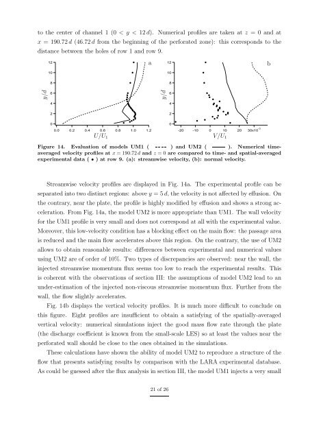
Figure 14. Evaluation of mo<strong>de</strong>ls UM1 ( ) and UM2 ( ). Numerical timeaveraged<br />
velocity profiles at x = 190.72 d and z = 0 are compared to time- and spatial-averaged<br />
experimental data ( • ) at row 9. (a): streamwise velocity, (b): normal velocity.<br />
Streamwise velocity profiles are displayed in Fig. 14a. The experimental profile can be<br />
separated into two distinct regions: above y = 5 d, the velocity is not affected by effusion. On<br />
the contrary, near the plate, the profile is highly modified by effusion and shows a strong acceleration.<br />
From Fig. 14a, the mo<strong>de</strong>l UM2 is more appropriate than UM1. The wall velocity<br />
for the UM1 profile is very small and does not correspond at all with the experimental value.<br />
Moreover, this low-velocity condition has a blocking effect on the main flow: the passage area<br />
is reduced and the main flow accelerates above this region. On the contrary, the use of UM2<br />
allows to obtain reasonable results: differences b<strong>et</strong>ween experimental and numerical values<br />
using UM2 are of or<strong>de</strong>r of 10%. Two types of discrepancies are observed: near the wall, the<br />
injected streamwise momentum flux seems too low to reach the experimental results. This<br />
is coherent with the observations of section III: the assumptions of mo<strong>de</strong>l UM2 lead to an<br />
un<strong>de</strong>r-estimation of the injected non-viscous streamwise momentum flux. Further from the<br />
wall, the flow slightly accelerates.<br />
Fig. 14b displays the vertical velocity profiles. It is much more difficult to conclu<strong>de</strong> on<br />
this figure. Eight profiles are insufficient to obtain a satisfying of the spatially-averaged<br />
vertical velocity: numerical <strong>simulation</strong>s inject the good mass flow rate through the plate<br />
(the discharge coefficient is known from the small-scale LES) so at least the values near the<br />
perforated wall should be close to the ones obtained in the <strong>simulation</strong>s.<br />
These calculations have shown the ability of mo<strong>de</strong>l UM2 to reproduce a structure of the<br />
flow that presents satisfying results by comparison with the LARA experimental database.<br />
As could be guessed after the flux analysis in section III, the mo<strong>de</strong>l UM1 injects a very small<br />
21 of 26


