these simulation numerique et modelisation de l'ecoulement autour ...
these simulation numerique et modelisation de l'ecoulement autour ... these simulation numerique et modelisation de l'ecoulement autour ...
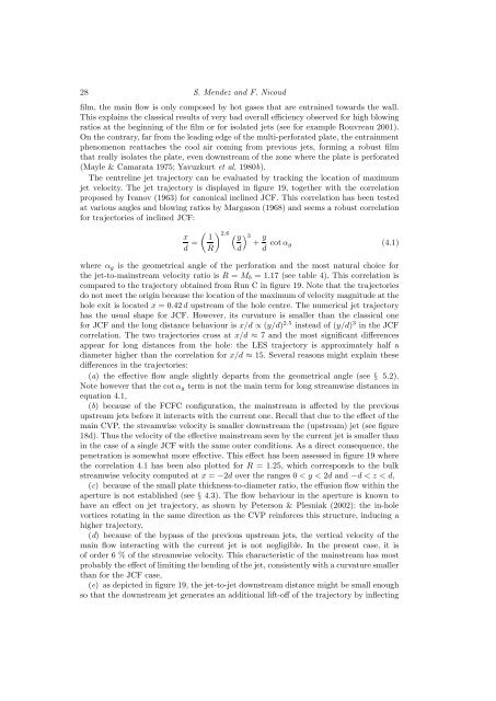
LES of a bi-periodic turbulent flow with effusion 27 Figure 18. Description of the jet and its wake. (a): Contours and isolines of the time-averaged streamwise velocity on the mid plane z = 0. (b): Contours and isolines of the streamwise RMS velocity on the mid plane z = 0. (c): Contours and isolines of the vertical RMS velocity on the mid plane z = 0. (d): Contours of the time-averaged vertical velocity on a plane normal to the direction of the crossflow, visualised in (a) by a black vertical line (x = 3 d, zoom on the near-wall region). White isolines of the time-averaged streamwise velocity (same values as in a). Black isolines of the Q criterion (Q = V j 2 /d 2 ) to show the counter-rotating vortex pair. 2006). Figure 18(c) displays the field of vertical RMS velocity in the mid plane z = 0. High levels of velocity fluctuations are observed in the in-hole separation zone and at the windward edge of the jet (6). Figure 18(d) shows the contours of the time-averaged vertical velocity. Black isolines of Q criterion (Q = V j 2 /d 2 ) are used to locate the two main vortices of the wake. White isolines of time-averaged streamwise velocity allow observation of the location of the jet core. From figure 18(d), the jet (7) conserves the kidney shape it has in the hole (see § 4.3) after it penetrates the main stream. However, it is no longer confined by the walls of the hole and it becomes wider (approximately 1.6 d). The two counter-rotating vortices forming the CVP (see figure 15) are located under the jet, and the distance between their centres is approximately 0.6 d. They induce a zone of low streamwise and high vertical velocity between them (8). Figure 18(d) also shows how the main flow is convected near the wall (negative vertical velocity is observed on both sides of the jet (9)) and then decelerated in the streamwise direction (8) under the effect of the two counter-rotating vortices under the jet. Note that the vertical velocity under the jet (8) is actually larger than in the jet itself (7). These features are related to the entrainment effect, responsible for the whole structure of the film. In non-isothermal cases, at the beginning of a cooling
28 S. Mendez and F. Nicoud film, the main flow is only composed by hot gases that are entrained towards the wall. This explains the classical results of very bad overall efficiency observed for high blowing ratios at the beginning of the film or for isolated jets (see for example Rouvreau 2001). On the contrary, far from the leading edge of the multi-perforated plate, the entrainment phenomenon reattaches the cool air coming from previous jets, forming a robust film that really isolates the plate, even downstream of the zone where the plate is perforated (Mayle & Camarata 1975; Yavuzkurt et al. 1980b). The centreline jet trajectory can be evaluated by tracking the location of maximum jet velocity. The jet trajectory is displayed in figure 19, together with the correlation proposed by Ivanov (1963) for canonical inclined JCF. This correlation has been tested at various angles and blowing ratios by Margason (1968) and seems a robust correlation for trajectories of inclined JCF: ( 2.6 x 1 (y ) 3 d R) = y + d d cotα g (4.1) where α g is the geometrical angle of the perforation and the most natural choice for the jet-to-mainstream velocity ratio is R = M b = 1.17 (see table 4). This correlation is compared to the trajectory obtained from Run C in figure 19. Note that the trajectories do not meet the origin because the location of the maximum of velocity magnitude at the hole exit is located x = 0.42 d upstream of the hole centre. The numerical jet trajectory has the usual shape for JCF. However, its curvature is smaller than the classical one for JCF and the long distance behaviour is x/d ∝ (y/d) 2.5 instead of (y/d) 3 in the JCF correlation. The two trajectories cross at x/d ≈ 7 and the most significant differences appear for long distances from the hole: the LES trajectory is approximately half a diameter higher than the correlation for x/d ≈ 15. Several reasons might explain these differences in the trajectories: (a) the effective flow angle slightly departs from the geometrical angle (see § 5.2). Note however that the cotα g term is not the main term for long streamwise distances in equation 4.1, (b) because of the FCFC configuration, the mainstream is affected by the previous upstream jets before it interacts with the current one. Recall that due to the effect of the main CVP, the streamwise velocity is smaller downstream the (upstream) jet (see figure 18d). Thus the velocity of the effective mainstream seen by the current jet is smaller than in the case of a single JCF with the same outer conditions. As a direct consequence, the penetration is somewhat more effective. This effect has been assessed in figure 19 where the correlation 4.1 has been also plotted for R = 1.25, which corresponds to the bulk streamwise velocity computed at x = −2d over the ranges 0 < y < 2d and −d < z < d, (c) because of the small plate thickness-to-diameter ratio, the effusion flow within the aperture is not established (see § 4.3). The flow behaviour in the aperture is known to have an effect on jet trajectory, as shown by Peterson & Plesniak (2002): the in-hole vortices rotating in the same direction as the CVP reinforces this structure, inducing a higher trajectory, (d) because of the bypass of the previous upstream jets, the vertical velocity of the main flow interacting with the current jet is not negligible. In the present case, it is of order 6 % of the streamwise velocity. This characteristic of the mainstream has most probably the effect of limiting the bending of the jet, consistently with a curvature smaller than for the JCF case, (e) as depicted in figure 19, the jet-to-jet downstream distance might be small enough so that the downstream jet generates an additional lift-off of the trajectory by inflecting
- Page 73 and 74: 3.3 Le code de calcul AVBP 3.3.1 As
- Page 75 and 76: 3.3 Le code de calcul AVBP dans le
- Page 77 and 78: 3.3 Le code de calcul AVBP de sa st
- Page 79 and 80: Chapitre 4 Simulations numériques
- Page 81 and 82: 4.1 Quelles simulations pour la mod
- Page 83 and 84: 4.2 Choix de la méthode de simulat
- Page 85 and 86: 4.2 Choix de la méthode de simulat
- Page 87 and 88: 4.3 Sensibilité des simulations au
- Page 89 and 90: 4.3 Sensibilité des simulations au
- Page 91 and 92: 4.3 Sensibilité des simulations au
- Page 93 and 94: 4.3 Sensibilité des simulations au
- Page 95 and 96: 4.3 Sensibilité des simulations au
- Page 97 and 98: Chapitre 5 Simulations numériques
- Page 99 and 100: 2 S. Mendez and F. Nicoud COMBUSTIO
- Page 101 and 102: 4 S. Mendez and F. Nicoud (c) The i
- Page 103 and 104: 6 S. Mendez and F. Nicoud CALCULATI
- Page 105 and 106: 8 S. Mendez and F. Nicoud Name Numb
- Page 107 and 108: 10 S. Mendez and F. Nicoud x/d z/d
- Page 109 and 110: 12 S. Mendez and F. Nicoud main, it
- Page 111 and 112: 14 S. Mendez and F. Nicoud 1.0 a 1.
- Page 113 and 114: 16 S. Mendez and F. Nicoud ROWS 1 3
- Page 115 and 116: 18 S. Mendez and F. Nicoud Figure 1
- Page 117 and 118: 20 S. Mendez and F. Nicoud 30 ◦ 3
- Page 119 and 120: 22 S. Mendez and F. Nicoud & Mahesh
- Page 121 and 122: 24 S. Mendez and F. Nicoud Figure 1
- Page 123: 26 S. Mendez and F. Nicoud Figure 1
- Page 127 and 128: 30 S. Mendez and F. Nicoud Region t
- Page 129 and 130: 32 S. Mendez and F. Nicoud Expressi
- Page 131 and 132: 34 S. Mendez and F. Nicoud geometri
- Page 133 and 134: 36 S. Mendez and F. Nicoud (f) Two
- Page 135 and 136: 38 S. Mendez and F. Nicoud Mendez,
- Page 137 and 138: Chapitre 6 Un modèle adiabatique p
- Page 139 and 140: ρ Mass density, kg/m 3 P T V i τ
- Page 141 and 142: cence of the jets. This is particul
- Page 143 and 144: Simulations. The small-scale LES re
- Page 145 and 146: chosen to compare with numerical re
- Page 147 and 148: pressure drop of 41 Pa is effective
- Page 149 and 150: Region total plate hole solid wall
- Page 151 and 152: This equality is almost verified at
- Page 153 and 154: V U σ V inj jet cotan(α′ ) V U
- Page 155 and 156: PERIODIC Z INFLOW 1 WALL 24 OUTFLOW
- Page 157 and 158: part of the plate. Downstream of th
- Page 159 and 160: streamwise momentum flux. As a cons
- Page 161 and 162: 8 Fric, T. and Roshko, A., “Vorti
- Page 163 and 164: Discussion sur la modélisation de
- Page 165 and 166: 20 15 10 y/d 5 0 -5 -10 0.0 0.2 0.4
- Page 167 and 168: Chapitre 7 Simulations numériques
- Page 169 and 170: Primary flow (burnt gases) Secondar
- Page 171 and 172: Figure 7: Nusselt number over the s
- Page 173 and 174: the perforated plate. A Large-Eddy
28 S. Men<strong>de</strong>z and F. Nicoud<br />
film, the main flow is only composed by hot gases that are entrained towards the wall.<br />
This explains the classical results of very bad overall efficiency observed for high blowing<br />
ratios at the beginning of the film or for isolated j<strong>et</strong>s (see for example Rouvreau 2001).<br />
On the contrary, far from the leading edge of the multi-perforated plate, the entrainment<br />
phenomenon reattaches the cool air coming from previous j<strong>et</strong>s, forming a robust film<br />
that really isolates the plate, even downstream of the zone where the plate is perforated<br />
(Mayle & Camarata 1975; Yavuzkurt <strong>et</strong> al. 1980b).<br />
The centreline j<strong>et</strong> trajectory can be evaluated by tracking the location of maximum<br />
j<strong>et</strong> velocity. The j<strong>et</strong> trajectory is displayed in figure 19, tog<strong>et</strong>her with the correlation<br />
proposed by Ivanov (1963) for canonical inclined JCF. This correlation has been tested<br />
at various angles and blowing ratios by Margason (1968) and seems a robust correlation<br />
for trajectories of inclined JCF:<br />
( 2.6<br />
x 1 (y ) 3<br />
d R) = y +<br />
d d cotα g (4.1)<br />
where α g is the geom<strong>et</strong>rical angle of the perforation and the most natural choice for<br />
the j<strong>et</strong>-to-mainstream velocity ratio is R = M b = 1.17 (see table 4). This correlation is<br />
compared to the trajectory obtained from Run C in figure 19. Note that the trajectories<br />
do not me<strong>et</strong> the origin because the location of the maximum of velocity magnitu<strong>de</strong> at the<br />
hole exit is located x = 0.42 d upstream of the hole centre. The numerical j<strong>et</strong> trajectory<br />
has the usual shape for JCF. However, its curvature is smaller than the classical one<br />
for JCF and the long distance behaviour is x/d ∝ (y/d) 2.5 instead of (y/d) 3 in the JCF<br />
correlation. The two trajectories cross at x/d ≈ 7 and the most significant differences<br />
appear for long distances from the hole: the LES trajectory is approximately half a<br />
diam<strong>et</strong>er higher than the correlation for x/d ≈ 15. Several reasons might explain <strong>these</strong><br />
differences in the trajectories:<br />
(a) the effective flow angle slightly <strong>de</strong>parts from the geom<strong>et</strong>rical angle (see § 5.2).<br />
Note however that the cotα g term is not the main term for long streamwise distances in<br />
equation 4.1,<br />
(b) because of the FCFC configuration, the mainstream is affected by the previous<br />
upstream j<strong>et</strong>s before it interacts with the current one. Recall that due to the effect of the<br />
main CVP, the streamwise velocity is smaller downstream the (upstream) j<strong>et</strong> (see figure<br />
18d). Thus the velocity of the effective mainstream seen by the current j<strong>et</strong> is smaller than<br />
in the case of a single JCF with the same outer conditions. As a direct consequence, the<br />
pen<strong>et</strong>ration is somewhat more effective. This effect has been assessed in figure 19 where<br />
the correlation 4.1 has been also plotted for R = 1.25, which corresponds to the bulk<br />
streamwise velocity computed at x = −2d over the ranges 0 < y < 2d and −d < z < d,<br />
(c) because of the small plate thickness-to-diam<strong>et</strong>er ratio, the effusion flow within the<br />
aperture is not established (see § 4.3). The flow behaviour in the aperture is known to<br />
have an effect on j<strong>et</strong> trajectory, as shown by P<strong>et</strong>erson & Plesniak (2002): the in-hole<br />
vortices rotating in the same direction as the CVP reinforces this structure, inducing a<br />
higher trajectory,<br />
(d) because of the bypass of the previous upstream j<strong>et</strong>s, the vertical velocity of the<br />
main flow interacting with the current j<strong>et</strong> is not negligible. In the present case, it is<br />
of or<strong>de</strong>r 6 % of the streamwise velocity. This characteristic of the mainstream has most<br />
probably the effect of limiting the bending of the j<strong>et</strong>, consistently with a curvature smaller<br />
than for the JCF case,<br />
(e) as <strong>de</strong>picted in figure 19, the j<strong>et</strong>-to-j<strong>et</strong> downstream distance might be small enough<br />
so that the downstream j<strong>et</strong> generates an additional lift-off of the trajectory by inflecting


