

these simulation numerique et modelisation de l'ecoulement autour ...
these simulation numerique et modelisation de l'ecoulement autour ...
these simulation numerique et modelisation de l'ecoulement autour ...

You also want an ePaper? Increase the reach of your titles
YUMPU automatically turns print PDFs into web optimized ePapers that Google loves.
LES of a bi-periodic turbulent flow with effusion 19<br />
SUCTION WALL<br />
y<br />
z<br />
x<br />
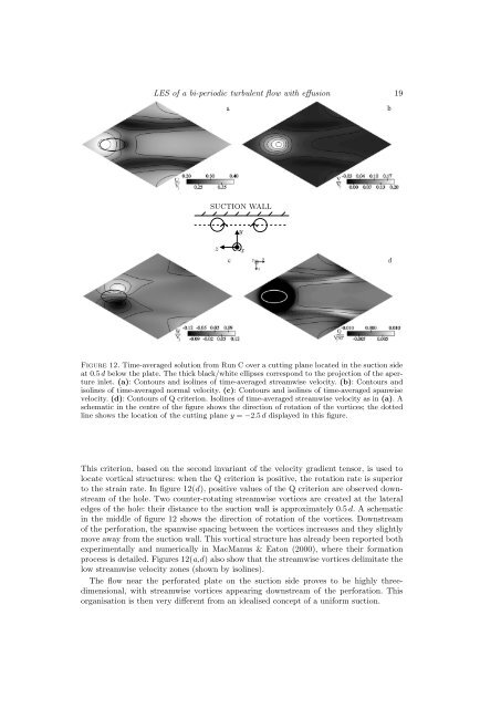
Figure 12. Time-averaged solution from Run C over a cutting plane located in the suction si<strong>de</strong><br />
at 0.5 d below the plate. The thick black/white ellipses correspond to the projection of the aperture<br />
inl<strong>et</strong>. (a): Contours and isolines of time-averaged streamwise velocity. (b): Contours and<br />
isolines of time-averaged normal velocity. (c): Contours and isolines of time-averaged spanwise<br />
velocity. (d): Contours of Q criterion. Isolines of time-averaged streamwise velocity as in (a). A<br />
schematic in the centre of the figure shows the direction of rotation of the vortices; the dotted<br />
line shows the location of the cutting plane y = −2.5 d displayed in this figure.<br />
This criterion, based on the second invariant of the velocity gradient tensor, is used to<br />
locate vortical structures: when the Q criterion is positive, the rotation rate is superior<br />
to the strain rate. In figure 12(d), positive values of the Q criterion are observed downstream<br />
of the hole. Two counter-rotating streamwise vortices are created at the lateral<br />
edges of the hole: their distance to the suction wall is approximately 0.5 d. A schematic<br />
in the middle of figure 12 shows the direction of rotation of the vortices. Downstream<br />
of the perforation, the spanwise spacing b<strong>et</strong>ween the vortices increases and they slightly<br />
move away from the suction wall. This vortical structure has already been reported both<br />
experimentally and numerically in MacManus & Eaton (2000), where their formation<br />
process is d<strong>et</strong>ailed. Figures 12(a,d) also show that the streamwise vortices <strong>de</strong>limitate the<br />
low streamwise velocity zones (shown by isolines).<br />
The flow near the perforated plate on the suction si<strong>de</strong> proves to be highly threedimensional,<br />
with streamwise vortices appearing downstream of the perforation. This<br />
organisation is then very different from an i<strong>de</strong>alised concept of a uniform suction.


