BayStack 150-series Ethernet Hubs - K12 - Plano ISD
BayStack 150-series Ethernet Hubs - K12 - Plano ISD
BayStack 150-series Ethernet Hubs - K12 - Plano ISD

You also want an ePaper? Increase the reach of your titles
YUMPU automatically turns print PDFs into web optimized ePapers that Google loves.
<strong>BayStack</strong> <strong>150</strong>-<strong>series</strong><br />
<strong>Ethernet</strong> <strong>Hubs</strong><br />
Installation Instructions<br />
Installationsanweisungen<br />
Guide d’installation<br />
Instrucciones para la instalación<br />
Istruzioni per l’installazione<br />
Part No. 893-01028-A<br />
June 1997
© 1997 by Bay Networks, Inc. All rights reserved. Bay Networks is a registered trademark of Bay Networks, Inc. <strong>BayStack</strong><br />
is a trademark of Bay Networks, Inc.<br />
© 1997 Bay Networks, Inc. Alle Rechte vorbehalten. Bay Networks ist ein eingetragenes Warenzeichen von Bay Networks,<br />
Inc. <strong>BayStack</strong> ist ein Warenzeichen der Bay Networks, Inc.<br />
© 1997 par Bay Networks, Inc. Tous droits réservés. Bay Networks est une marque déposée de Bay Networks, In<br />
<strong>BayStack</strong> est une marque de fabrique de Bay Networks, Inc.<br />
© 1997 por Bay Networks, Inc. Todos los derechos reservados. Bay Networks es una marca registrada de Bay Networks,<br />
Inc. <strong>BayStack</strong> es una marca comercial de Bay Networks, Inc.<br />
© 1997 Bay Networks, Inc. Tutti i diritti riservati. Bay Networks è un marchio registrato di Bay Networks, Inc. <strong>BayStack</strong> è<br />
un marchio di fabbrica di Bay Networks, Inc.<br />
Statement of Conditions<br />
In the interest of improving internal design, operational function, and/or reliability, Bay Networks, Inc. reserves the right to<br />
make changes to the products described in this document without notice. Bay Networks, Inc. does not assume any liability<br />
that may occur due to the use or application of the product(s) or circuit layout(s) described herein.<br />
Erklärung<br />
Zur Verbesserung von internem Design, Funktionsfähigkeit und/oder Zuverlässigkeit behält sich Bay Networks, Inc.<br />
Änderungen hinsichtlich des im vorliegenden Dokument beschriebenen Produktes ohne vorherige Ankündigung vor. Bay<br />
Networks, Inc. übernimmt keinerlei Haftung aufgrund des Einsatzes oder der Anwendung des/der hier beschriebenen<br />
Produktes/Produkte oder Schaltpläne.<br />
Conditions<br />
Afin d’ameliorer la conception interne, les fonctionnalités et la fiabilité de ses produits, Bay Networks, Inc. se reserve le<br />
droit d’apporter sans préavis des modifications aux produits décrits dans ce document. Bay Networks ne saurait être tenu<br />
responsable de tout prejudice lié àl’emploi du ou des produits ou circuits décrits dans le présent document.<br />
Cláusula de condiciones<br />
En interés de mejora de diseños internos, funciones operativas y fiabilidad, Bay Networks se reserva el derecho de efectuar<br />
cambios en los productos descritos en este documento sin notificación previa. Bay Networks, Inc. no asume ninguna<br />
responsabilidad de los hechos que pudieran producirse debido al uso o aplicación del producto o productos o diseño o<br />
diseños de circuitos descritos en este manual.<br />
Dichiarazione delle condizioni<br />
Nell’interesse del miglioramento della struttura interna, delle caratteristiche operative e/o della sicurezza, Bay Networks,<br />
Inc. si riserva il diritto di apportare modifiche senza preavviso ai prodotti descritti nel presente documento. Bay Networks,<br />
Inc. non si assume impegni connessi all’uso o all’applicazione dei prodotti o dei circuiti qui descritti.<br />
ii
Federal Communications Commission (FCC) Statement<br />
Note: This equipment has been tested and found to comply with the limits for a Class A digital device, pursuant to Part 15<br />
of the FCC rules. These limits are designed to provide reasonable protection against harmful interference when the<br />
equipment is operated in a commercial environment. This equipment generates, uses, and can radiate radio frequency<br />
energy. If it is not installed and used in accordance with the instruction manual, it may cause harmful interference to radio<br />
communications. Operation of this equipment in a residential area is likely to cause harmful interference, in which case<br />
users will be required to take whatever measures may be necessary to correct the interference at their own expense.<br />
EN 55 022 Declaration of Conformance<br />
This is to certify that the Bay Networks <strong>BayStack</strong> <strong>150</strong>-<strong>series</strong> <strong>Ethernet</strong> hubs are shielded against the generation of radio<br />
interference in accordance with the application of Council Directive 89/336/EEC, Article 4a. Conformity is declared by the<br />
application of EN 55 022 Class A (CISPR 22).<br />
Caution: This device is a Class A product. In a domestic environment, this device can cause radio<br />
interference, in which case, the user may be required to take appropriate measures.<br />
Achtung: Dieses Gerät ist ein Produkt der Klasse A. Bei Heiminstallationen kann dieses Gerät Störungen<br />
des Rundfunkempfangs verursachen, wodurch der Benutzer gegebenenfalls entsprechende Maßnahmen<br />
ergreifen muß.<br />
Attention: Appareil électrique de classe A pouvant causer des radio-interférences en utilisation domestique<br />
et nécessiter, le cas échéant, l'application de mesures correctives appropriées.<br />
Precaución: Este dispositivo es un producto de la Clase A. En un entorno doméstico, este dispositivo puede<br />
producir interferencias de radio, en cuyo caso, puede exigirse al usuario que tome las medidas de corrección<br />
apropiadas.<br />
Attenzione: Questo dispositivo è un prodotto di Classe A. Se utilizzato in ambiente domestico, può causare<br />
interferenze radio e, in tal caso, l'utente dovrà prendere le opportune precauzioni.<br />
iii
Contents<br />
Installation Instructions................................................................................................................. 1<br />
Installationsanweisungen .............................................................................................................. 7<br />
Guide d’installation..................................................................................................................... 13<br />
Instrucciones para la instalación ................................................................................................. 19<br />
Istruzioni per l’installazione ....................................................................................................... 25<br />
.......................................................................................................................... 31<br />
iv
About This Guide<br />
This guide provides instructions for unpacking, installing, and connecting the <strong>BayStack</strong> <strong>150</strong>-<strong>series</strong><br />
hubs. Refer to Installation and Reference for the <strong>BayStack</strong> <strong>150</strong>-<strong>series</strong> <strong>Ethernet</strong> <strong>Hubs</strong> (Bay Networks ®<br />
part number 893-01021-A) for more detailed information.<br />
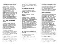
Unpacking<br />
Refer to the drawing numbers for descriptions of the parts in the box.<br />
1<br />
2<br />
4<br />
3<br />
6<br />
5<br />
7536FB<br />
Number<br />
Description<br />
1 AC power cord<br />
2 Self-adhesive rubber feet<br />
3 Mounting brackets (two) and screws<br />
4 This Guide: Installing the <strong>BayStack</strong> <strong>150</strong>-<strong>series</strong> <strong>Ethernet</strong> <strong>Hubs</strong><br />
5 <strong>BayStack</strong> <strong>150</strong>-<strong>series</strong> <strong>Ethernet</strong> hubs: <strong>BayStack</strong> <strong>150</strong> hub (24-port with built-in NMM * )<br />
<strong>BayStack</strong> 151 hub (24-port)<br />
<strong>BayStack</strong> 152 hub (12-port with built-in NMM)<br />
<strong>BayStack</strong>153 hub (12-port)<br />
6 Transceiver tray for AUI connection<br />
* NMM = Network management module<br />
1
Installing the Hub on a Flat Surface<br />
7676FA<br />
7675FA<br />
1. Attach the four self-adhesive rubber feet to<br />
the marked locations.<br />
2. Set the hub on a flat surface with 2 inches<br />
(5 cm) on each side for ventilation.<br />
Installing the Hub in a Rack<br />
Required Tool: #2 Phillips screwdriver<br />
1. Determine the best position for the hub in the rack.<br />
Note: For managed configurations, each stack of hubs must include at least one managed<br />
hub (<strong>BayStack</strong> <strong>150</strong> or 152 hub) placed at the top of the stack.<br />
.<br />
7677FA<br />
2. Attach the mounting brackets to the hub with<br />
the machine screws in the rack-mount kit.<br />
7678FA<br />
3. Mount the hub in the rack and insert and<br />
tighten the rack-mount screws.<br />
2
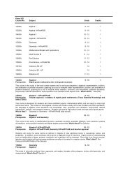
<strong>BayStack</strong> <strong>150</strong>-<strong>series</strong> Front and Rear Panels<br />
Refer to the numbers on the front and rear panel illustrations when connecting the hubs.<br />
Number Description Function<br />
1 LED indicators Indicate port and hub status<br />
2 HUB ID LED Indicates hub identification number<br />
3 MDI/MDI-X switch Configures port 1 to MDI (Uplink) or MDI-X (Normal)<br />
4 10 BASE-T <strong>Ethernet</strong> ports RJ-45 ports for connecting to other devices<br />
<strong>BayStack</strong> <strong>150</strong> <strong>Ethernet</strong> Hub Front Panel<br />
1<br />
2 3<br />
4<br />
12<br />
Master<br />
Con AUI Runt F/A L/C Other Isolate In Out<br />
1 2 3 4 5 6 7 8 9 10 11 12<br />
Hub ID<br />
1<br />
1 2 3 4 5 6<br />
7 8 9 10 11 12<br />
Link/Rx Disable Auto Part<br />
MDI<br />
MDI-X<br />
13 14 15 16 17 18 19 20 21 22 23 34<br />
<strong>150</strong> 10BASE-T HUB<br />
3 5 10 20 >40<br />
1 1 10 5 >20<br />
Utilization %<br />
Collision<br />
13 14 15 16 17 18<br />
19 20 21 22 23 24<br />
7671EA<br />
<strong>BayStack</strong> 151 <strong>Ethernet</strong> Hub Front Panel<br />
1<br />
2 3<br />
4<br />
12<br />
AUI CoL<br />
Isolate In Out<br />
1 2 3 4 5 6 7 8 9 10 11 12<br />
Hub ID<br />
1<br />
1 2 3 4 5 6<br />
7 8 9 10 11 12<br />
Link/Rx Disable Auto Part<br />
MDI<br />
MDI-X<br />
13 14 15 16 17 18<br />
151 10BASE-T HUB<br />
1 3 5 10 20 >40<br />
19 20 21 22 23 34<br />
Utilization %<br />
13 14 15 16 17 18<br />
19 20 21 22 23 24<br />
7672EA<br />
<strong>BayStack</strong> 152 <strong>Ethernet</strong> Hub Front Panel<br />
1<br />
2 3<br />
4<br />
12<br />
Master<br />
Con AUI Runt F/A L/C Other Isolate In Out<br />
1 2 3 4 5 6<br />
Hub ID<br />
1<br />
1 2 3 4 5 6<br />
Link/Rx<br />
Disable/Auto Part<br />
MDI<br />
MDI-X<br />
152 10BASE-T HUB<br />
7 8 9 10 11 12<br />
3 5 10 20 >40<br />
1 1 10 5 >20<br />
Utilization %<br />
Collision<br />
13 14 15 16 17 18<br />
7673EA<br />
3
<strong>BayStack</strong> 153 <strong>Ethernet</strong> Hub Front Panel<br />
Number Description Function<br />
1 LED indicators Indicate port and hub status<br />
2 HUB ID LED Indicates hub identification number<br />
3 MDI/MDI-X switch Configures port 1 to MDI (Uplink) or MDI-X (Normal)<br />
4 10 BASE-T <strong>Ethernet</strong> ports RJ-45 ports for connecting to other devices<br />
1<br />
2 3<br />
4<br />
12<br />
AUI<br />
Col<br />
1 2 3 4 5 6<br />
Isolate In Out<br />
Hub ID<br />
1<br />
1 2 3 4 5 6<br />
Link/Rx<br />
Disable/Auto Part<br />
MDI<br />
MDI-X<br />
153 10BASE-T HUB<br />
7 8 9 10 11 12<br />
1 3 5 10 20 >40<br />
Utilization %<br />
13 14 15 16 17 18<br />
7674EA<br />
The <strong>BayStack</strong> <strong>150</strong>-<strong>series</strong> Hub Rear Panel<br />
Number Description Function<br />
5 Communications port<br />
RS-232 connection to the console<br />
(<strong>BayStack</strong> <strong>150</strong> and 152 hubs only)<br />
6 Cascade In and Out ports Used to connect hubs together in a stack<br />
7 Power connector Connects to AC power using power cord standard for the<br />
country of installation<br />
5 6 7<br />
Comm Port<br />
In<br />
Cascade<br />
Out<br />
AC LINE<br />
100-240 VAC<br />
50-60 Hz<br />
1.5A MAX<br />
7679EA<br />
4
Cascading <strong>Hubs</strong><br />
Comm Port<br />
Cascade<br />
In<br />
Out<br />
In<br />
Cascade<br />
Out<br />
In<br />
Cascade<br />
Out<br />
7640EA<br />
To connect hubs together, use the Cascade In and Out ports (6) on the rear panel with unshielded<br />
twisted pair (UTP) or shielded twisted pair (STP) cable terminated at each end with an RJ-45 plug.<br />
Connect the Out port of the first hub in the stack (a managed hub) to the In port of the next hub in<br />
the stack.<br />
Connecting to the Network<br />
1. Connect network devices to the hub RJ-45 10BASE-T <strong>Ethernet</strong> ports (4) with STP or UTP<br />
cables. Port 1 can be configured as an MDI (Uplink) port or an MDI-X (Normal) port using<br />
the MDI/MDI-X switch (3). All other ports are MDI-X (normal).<br />
2. Use the RS-232 Communications port (5) on managed hubs (<strong>BayStack</strong> <strong>150</strong> and 152 hubs)<br />
to connect to a PC or terminal to monitor and configure hubs.<br />
For detailed information, refer to Chapter 3, “Installation,” of Installation and Reference for the<br />
<strong>BayStack</strong> <strong>150</strong>-<strong>series</strong> <strong>Ethernet</strong> <strong>Hubs</strong>.<br />
5
Applying Power to the Hub<br />
1. Verify that you have the correct power cord for your region.<br />
Caution: Use only power cords with a grounding path. Without a proper ground, a person<br />
touching the unit is in danger of receiving an electrical shock. Lack of a grounding path to the<br />
unit may result in excessive emissions.<br />
.<br />
AC LINE<br />
100-240 VAC<br />
50-60 Hz<br />
1.5A MAX<br />
7670FA<br />
2. Attach the power cord to the back of the hub.<br />
3. With power applied, the managed hub does a power-on self-test (POST) to verify that ports and<br />
hub connections are working. Verify that Link LEDs light for all connected ports.<br />
4. If the managed hub is connected to a terminal or PC, the BootP process automatically begins.<br />
Press [Ctrl]+C before the process stops to prepare for configuring the hub.<br />
5. Refer to Chapter 4 of Installation and Reference for the <strong>BayStack</strong> <strong>150</strong>-<strong>series</strong> <strong>Ethernet</strong> <strong>Hubs</strong> for<br />
procedures to configure the hub.<br />
6
Über dieses Handbuch<br />
Dieses Handbuch enthält Hinweise zum Auspacken, Installieren und Anschließen der<br />
<strong>BayStack</strong> -<strong>Hubs</strong> der Serie <strong>150</strong>. Ausführliche Informationen finden Sie in Installation and Reference<br />
for the <strong>BayStack</strong> <strong>150</strong>-<strong>series</strong> <strong>Ethernet</strong> <strong>Hubs</strong> (Bay Networks ® Teilenummer 893-01021-A).<br />
Auspacken<br />
Die im Lieferumfang enthaltenen Komponenten können Sie anhand der Nummern in der Abbildung<br />
und in der Tabelle identifizieren.<br />
1<br />
2<br />
4<br />
3<br />
6<br />
5<br />
7536FB<br />
Nummer<br />
Bezeichnung<br />
1 Netzkabel (für Wechselstrom)<br />
2 Selbstklebende Gummifüße<br />
3 Halterungen (zwei) und Schrauben<br />
4 Dieses Handbuch: Installieren der <strong>BayStack</strong> <strong>Ethernet</strong>-<strong>Hubs</strong> der Serie <strong>150</strong><br />
5 <strong>BayStack</strong> <strong>Ethernet</strong>-Hub der<br />
Serie <strong>150</strong>:<br />
6 Transceiver-Fach für AUI-Anschluß<br />
* NMM = Netzwerkmanagementmodul<br />
<strong>BayStack</strong>-Hub <strong>150</strong> (24-polige Anschlüsse mit integriertem NMM * )<br />
<strong>BayStack</strong>-Hub 151 (24-polige Anschlüsse)<br />
<strong>BayStack</strong>-Hub 152 (12-polige Anschlüsse mit integriertem NMM)<br />
<strong>BayStack</strong>-Hub 153 (12-polige Anschlüsse)<br />
7
Aufstellen des <strong>Hubs</strong> auf einer ebenen Fläche<br />
7676FA<br />
7675FA<br />
1. Bringen Sie die vier selbstklebenden<br />
Gummifüße an den markierten Stellen an.<br />
2. Stellen Sie den Hub auf eine ebene Fläche.<br />
Lassen Sie dabei auf jeder Seite 5 cm frei,<br />
um eine gute Luftzirkulation zu<br />
gewährleisten.<br />
Einbauen des <strong>Hubs</strong> in ein Gerätegestell<br />
Benötigtes Werkzeug: Ein Kreuzschlitzschraubendreher Nr. 2<br />
1. Bestimmen Sie die beste Position des <strong>Hubs</strong> im Gestell.<br />
Hinweis: Fur Konfigurationen mit Managementzugriff, muß jeder Stack (mehrere <strong>Hubs</strong>)<br />
mindestens ein managed Hub (<strong>BayStack</strong> <strong>150</strong> oder 152 Hub) enthalten. Dieser muß als<br />
oberstes Hub im Stack installiert werden.<br />
.<br />
7677FA<br />
2. Befestigen Sie die Halterungen mit den im<br />
Gestelleinbausatz enthaltenen<br />
Maschinenschrauben am Hub.<br />
7678FA<br />
3. Setzen Sie den Hub in das Gestell ein, und<br />
befestigen Sie ihn mit den Schrauben für den<br />
Gestelleinbau.<br />
8
Frontblende und Rückwand der <strong>BayStack</strong>-<strong>Hubs</strong> der Serie <strong>150</strong><br />
Beim Anschließen der <strong>Hubs</strong> können Sie sich an die Anschlüsse anhand der Nummern in den<br />
Abbildungen zu Frontblende und Rückwand wenden.<br />
Nummer Bezeichnung Funktion<br />
1 LED-Anzeigen Zeigen den Status der Anschlüsse und des <strong>Hubs</strong> an.<br />
2 LED-Anzeige der Hub-ID Zeigt die Hub-Identifikationsnummer an.<br />
3 MDI/MDI-X-Schalter Dient der Einstellung von Anschluß 1 auf MDI (Uplink)<br />
oder MDI-X (Normal).<br />
4 10BASE-T <strong>Ethernet</strong>-Anschlüsse RJ-45-Schnittstellen für den Anschluß an andere Geräte.<br />
Frontblende des <strong>BayStack</strong> <strong>Ethernet</strong>-<strong>Hubs</strong> <strong>150</strong><br />
1<br />
2 3<br />
4<br />
12<br />
Master<br />
Con AUI Runt F/A L/C Other Isolate In Out<br />
1 2 3 4 5 6 7 8 9 10 11 12<br />
Hub ID<br />
1<br />
1 2 3 4 5 6<br />
7 8 9 10 11 12<br />
Link/Rx Disable Auto Part<br />
MDI<br />
MDI-X<br />
13 14 15 16 17 18 19 20 21 22 23 34<br />
<strong>150</strong> 10BASE-T HUB<br />
3 5 10 20 >40<br />
1 1 10 5 >20<br />
Utilization %<br />
Collision<br />
13 14 15 16 17 18<br />
19 20 21 22 23 24<br />
7671EA<br />
Frontblende des <strong>BayStack</strong> <strong>Ethernet</strong>-<strong>Hubs</strong> 151<br />
1<br />
2 3<br />
4<br />
12<br />
AUI CoL<br />
Isolate In Out<br />
1 2 3 4 5 6 7 8 9 10 11 12<br />
Hub ID<br />
1<br />
1 2 3 4 5 6<br />
7 8 9 10 11 12<br />
Link/Rx Disable Auto Part<br />
MDI<br />
MDI-X<br />
13 14 15 16 17 18<br />
151 10BASE-T HUB<br />
1 3 5 10 20 >40<br />
19 20 21 22 23 34<br />
Utilization %<br />
13 14 15 16 17 18<br />
19 20 21 22 23 24<br />
7672EA<br />
Frontblende des <strong>BayStack</strong> <strong>Ethernet</strong>-<strong>Hubs</strong> 152<br />
1<br />
2 3<br />
4<br />
12<br />
Master<br />
Con AUI Runt F/A L/C Other Isolate In Out<br />
1 2 3 4 5 6<br />
Hub ID<br />
1<br />
1 2 3 4 5 6<br />
Link/Rx<br />
Disable/Auto Part<br />
MDI<br />
MDI-X<br />
152 10BASE-T HUB<br />
7 8 9 10 11 12<br />
3 5 10 20 >40<br />
1 1 10 5 >20<br />
Utilization %<br />
Collision<br />
13 14 15 16 17 18<br />
7673EA<br />
9
Frontblende des <strong>BayStack</strong> <strong>Ethernet</strong>-<strong>Hubs</strong> 153<br />
Nummer Bezeichnung Funktion<br />
1 LED-Anzeigen Zeigen den Status der Anschlüsse und des <strong>Hubs</strong> an.<br />
2 LED-Anzeige der Hub-ID Zeigt die Hub-Identifikationsnummer an.<br />
3 MDI/MDI-X-Schalter Dient der Einstellung von Anschluß 1 auf MDI (Uplink)<br />
oder MDI-X (Normal).<br />
4 10BASE-T <strong>Ethernet</strong>-Anschlüsse RJ-45-Schnittstellen für den Anschluß an andere Geräte.<br />
1<br />
2 3<br />
4<br />
12<br />
AUI<br />
Col<br />
1 2 3 4 5 6<br />
Isolate In Out<br />
Hub ID<br />
1<br />
1 2 3 4 5 6<br />
Link/Rx<br />
Disable/Auto Part<br />
MDI<br />
MDI-X<br />
153 10BASE-T HUB<br />
7 8 9 10 11 12<br />
1 3 5 10 20 >40<br />
Utilization %<br />
13 14 15 16 17 18<br />
7674EA<br />
Rückwand der <strong>BayStack</strong>-<strong>Hubs</strong> der Serie <strong>150</strong><br />
Nummer Bezeichnung Funktion<br />
5 Kommunikationsport<br />
(nur <strong>BayStack</strong>-Hub-Modelle <strong>150</strong><br />
und 152)<br />
RS-232-Verbindung zur Konsole.<br />
6 Kaskadenanschlüsse Ein- und Dienen zur Verbindung von <strong>Hubs</strong> in einem Stapel.<br />
Ausgang<br />
7 Netzanschluß Dient für den Anschluß des <strong>Hubs</strong> an die Stromversorgung<br />
(Wechselspannung) über ein Standard-Netzkabel für das<br />
Land, in dem der Hub installiert wird.<br />
5 6 7<br />
Comm Port<br />
In<br />
Cascade<br />
Out<br />
AC LINE<br />
100-240 VAC<br />
50-60 Hz<br />
1.5A MAX<br />
7679EA<br />
10
Kaskadenförmige Verbindung von <strong>Hubs</strong><br />
Comm Port<br />
Cascade<br />
In<br />
Out<br />
In<br />
Cascade<br />
Out<br />
In<br />
Cascade<br />
Out<br />
7640EA<br />
<strong>Hubs</strong> werden über die in der Rückwand sitzenden Kaskadenanschlüsse Ein- und Ausgang (6)<br />
miteinander verbunden. Verwenden Sie dazu ein unabgeschirmtes verdrilltes Zwillingskabel (UTP)<br />
oder ein abgeschirmtes verdrilltes Zwillingskabel (STP), das an jedem Ende mit einem RJ-45-Stecker<br />
abschließt. Verbinden Sie den Anschluß Aus des ersten <strong>Hubs</strong> im Stapel (einem verwalteten Hub) mit<br />
dem Anschluß Ein des nächsten <strong>Hubs</strong> im Stapel.<br />
Anschluß an ein Netzwerk<br />
1. Netzwerkgeräte werden mittels STP- oder UTP-Kabel an die RJ-45 10BASE-T<br />
<strong>Ethernet</strong>-Anschlüsse des <strong>Hubs</strong> (4) angeschlossen. Mit dem MDI/MDI-X-Schalter (3) kann<br />
Anschluß 1 als MDI-Anschluß (Uplink) oder als MDI-X-Anschluß (Normal) konfiguriert werden.<br />
Alle anderen Anschlüsse sind auf MDI-X (Normal) eingestellt.<br />
2. Bei verwalteten <strong>Hubs</strong> (<strong>BayStack</strong>-Hub-Modelle <strong>150</strong> und 152) kann an den<br />
RS-232-Kommunikationsport (5) ein PC oder ein Terminal zur Überwachung und Konfiguration<br />
der <strong>Hubs</strong> angeschlossen werden.<br />
Ausführliche Informationen dazu finden Sie in Kapitel 3 “Installation” der Dokumentation Installation<br />
and Reference for the <strong>BayStack</strong> <strong>150</strong>-<strong>series</strong> <strong>Ethernet</strong> <strong>Hubs</strong>.<br />
11
Anschließen des <strong>Hubs</strong> an die Stromversorgung<br />
1. Stellen Sie sicher, daß das Netzkabel dem für Ihr Land geltenden Standard entspricht.<br />
Vorsicht: Verwenden Sie nur Netzkabel mit einem Schutzleiter. Ohne eine ordnungsgemäße<br />
Erdung besteht die Gefahr, daß eine Person bei Berührung des Geräts einen elektrischen<br />
Schlag bekommt. Weist das Gerät keinen Schutzleiter auf, kann dies übermäßige Emissionen<br />
zur Folge haben.<br />
.<br />
AC LINE<br />
100-240 VAC<br />
50-60 Hz<br />
1.5A MAX<br />
7670FA<br />
2. Schließen Sie das Netzkabel auf der Rückseite des <strong>Hubs</strong> an.<br />
3. Wenn der Hub mit Strom versorgt wird, führt er einen automatischen Selbsttest (POST) beim<br />
Einschalten aus, um zu prüfen, ob die Anschlüsse und Hub-Verbindungen funktionsfähig sind.<br />
Achten Sie darauf, ob die Verbindungs-LED-Anzeigen aller Anschlüsse, die eine Verbindung<br />
aufweisen, leuchten.<br />
4. Wenn das managed Hub mit einem Terminal oder einem PC verbunden ist, startet automatisch der<br />
Prozeß BootP. Drücken Sie vor Beendigung des Prozesses die Tastenkombination Strg+C, um den<br />
Hub zu konfigurieren.<br />
5. Anweisungen zur Konfiguration des <strong>Hubs</strong> finden Sie in Kapitel 4 der Dokumentation Installation<br />
and Reference for the <strong>BayStack</strong> <strong>150</strong>-<strong>series</strong> <strong>Ethernet</strong> <strong>Hubs</strong>.<br />
12
À propos de ce manuel<br />
Ce manuel fournit des instructions pour le déballage, l'installation et la connexion des concentrateurs<br />
<strong>BayStack</strong> <strong>150</strong>. Pour des informations plus détaillées, reportez-vous au manuel Installation et<br />
référence pour les concentrateurs <strong>Ethernet</strong> <strong>BayStack</strong> série <strong>150</strong> (numéro de pièce Bay Networks ®<br />
893-01021-A).<br />
Déballage<br />
Les numéros indiqués renvoient à la description des pièces contenues dans la boîte.<br />
1<br />
2<br />
4<br />
3<br />
6<br />
5<br />
7536FB<br />
Numéro<br />
Description<br />
1 Cordon d'alimentation<br />
2 Pieds autoadhésifs en caoutchouc<br />
3 Supports de montage (2) et vis<br />
4 Le présent guide: Installation des concentrateurs <strong>Ethernet</strong> <strong>BayStack</strong> <strong>150</strong><br />
5 Concentrateurs <strong>Ethernet</strong> <strong>BayStack</strong> <strong>150</strong>: Concentrateur <strong>BayStack</strong> <strong>150</strong> (24 ports, MGR * intégré)<br />
Concentrateur <strong>BayStack</strong> 151 (24 ports)<br />
Concentrateur <strong>BayStack</strong> 152 (12 ports, MGR intégré)<br />
Concentrateur <strong>BayStack</strong> 153 (12 ports)<br />
6 Plateau d'émetteur-récepteur pour connexion AVI<br />
* MGR = Module de gestion de réseau<br />
13
Installation du concentrateur sur une surface plate<br />
7<br />
7675FA<br />
1. Collez les quatre pieds autoadhésifs aux<br />
emplacements indiqués.<br />
2. Placez le concentrateur sur une surface<br />
plane, en veillant à dégager un espace de<br />
5cm minimum de chaque côté, pour assurer<br />
une ventilation adéquate.<br />
Installation du concentrateur sur châssis<br />
Outil requis: Tournevis Phillips no 2<br />
1. Déterminez le meilleur emplacement pour insérer le concentrateur dans le châssis.<br />
Nota: Pour les configurations gérées avec module de management, chaque rangée de<br />
concentrateurs doit comprendre au moins un concentrateur géré (concentrateur <strong>BayStack</strong><br />
<strong>150</strong> ou 152), placé au haut de la rangée.<br />
.<br />
2. Fixez les supports de montage sur le<br />
concentrateur à l'aide des vis fournies.<br />
7677FA<br />
7678FA<br />
3. Montez le concentrateur sur le châssis puis<br />
serrez les vis.<br />
14
Concentrateur <strong>BayStack</strong> série <strong>150</strong> - Panneaux avant et arrière<br />
Reportez-vous aux numéros indiqués sur les illustrations des panneaux avant et arrière pour connecter<br />
les concentrateurs.<br />
Numéro Description Fonction<br />
1 Voyants DEL Indiquent l'état des ports et du concentrateur<br />
2 DEL ID concentrateur Indique le numéro d'identification du concentrateur<br />
3 Commutateur MDI/MDI-X Configure le port 1 pour MDI (liaison montante) ou MDI-X (normal)<br />
4 Ports <strong>Ethernet</strong> 10BaseT Connecteurs RJ-45 pour le branchement d'autres concentrateurs<br />
Concentrateur <strong>Ethernet</strong> <strong>BayStack</strong> <strong>150</strong> - Panneau avant<br />
1<br />
2 3<br />
4<br />
12<br />
Master<br />
Con AUI Runt F/A L/C Other Isolate In Out<br />
1 2 3 4 5 6 7 8 9 10 11 12<br />
Hub ID<br />
1<br />
1 2 3 4 5 6<br />
7 8 9 10 11 12<br />
Link/Rx Disable Auto Part<br />
MDI<br />
MDI-X<br />
13 14 15 16 17 18 19 20 21 22 23 34<br />
<strong>150</strong> 10BASE-T HUB<br />
3 5 10 20 >40<br />
1 1 10 5 >20<br />
Utilization %<br />
Collision<br />
13 14 15 16 17 18<br />
19 20 21 22 23 24<br />
7671EA<br />
Concentrateur <strong>Ethernet</strong> <strong>BayStack</strong> 151 - Panneau avant<br />
1<br />
2 3<br />
4<br />
12<br />
AUI CoL<br />
Isolate In Out<br />
1 2 3 4 5 6 7 8 9 10 11 12<br />
Hub ID<br />
1<br />
1 2 3 4 5 6<br />
7 8 9 10 11 12<br />
Link/Rx Disable Auto Part<br />
MDI<br />
MDI-X<br />
13 14 15 16 17 18<br />
151 10BASE-T HUB<br />
1 3 5 10 20 >40<br />
19 20 21 22 23 34<br />
Utilization %<br />
13 14 15 16 17 18<br />
19 20 21 22 23 24<br />
7672EA<br />
Concentrateur <strong>Ethernet</strong> <strong>BayStack</strong> 152 - Panneau avant<br />
1<br />
2 3<br />
4<br />
12<br />
Master<br />
Con AUI Runt F/A L/C Other Isolate In Out<br />
1 2 3 4 5 6<br />
Hub ID<br />
1<br />
1 2 3 4 5 6<br />
Link/Rx<br />
Disable/Auto Part<br />
MDI<br />
MDI-X<br />
152 10BASE-T HUB<br />
7 8 9 10 11 12<br />
3 5 10 20 >40<br />
1 1 10 5 >20<br />
Utilization %<br />
Collision<br />
13 14 15 16 17 18<br />
7673EA<br />
15
Concentrateur <strong>Ethernet</strong> <strong>BayStack</strong> 153 - Panneau avant<br />
Numéro Description Fonction<br />
1 Voyants DEL Indiquent l'état des ports et du concentrateur<br />
2 DEL ID concentrateur Indique le numéro d'identification du concentrateur<br />
3 Commutateur MDI/MDI-X Configure le port 1 pour MDI (liaison montante) ou MDI-X<br />
(normal)<br />
4 Ports <strong>Ethernet</strong> 10BaseT Connecteurs RJ-45 pour le branchement d'autres<br />
concentrateurs<br />
1<br />
2 3<br />
4<br />
12<br />
AUI<br />
Col<br />
1 2 3 4 5 6<br />
Isolate In Out<br />
Hub ID<br />
1<br />
1 2 3 4 5 6<br />
Link/Rx<br />
Disable/Auto Part<br />
MDI<br />
MDI-X<br />
153 10BASE-T HUB<br />
7 8 9 10 11 12<br />
1 3 5 10 20 >40<br />
Utilization %<br />
13 14 15 16 17 18<br />
7674EA<br />
Concentrateur <strong>BayStack</strong> série <strong>150</strong> - Panneau arrière<br />
Numéro Description Fonction<br />
5 Port de communication<br />
(concentrateurs <strong>BayStack</strong> <strong>150</strong> et<br />
152 seulement)<br />
Connexion RS-232 vers la console<br />
6 Ports Cascade In (entrée) et Out Permet de connecter des concentrateurs en cascade<br />
(sortie) pour montage en cascade<br />
7 Connecteur d'alimentation Pour brancher le cordon d'alimentation<br />
5 6 7<br />
Comm Port<br />
In<br />
Cascade<br />
Out<br />
AC LINE<br />
100-240 VAC<br />
50-60 Hz<br />
1.5A MAX<br />
7679EA<br />
16
Concentrateurs en cascade<br />
Comm Port<br />
Cascade<br />
In<br />
Out<br />
In<br />
Cascade<br />
Out<br />
In<br />
Cascade<br />
Out<br />
7640EA<br />
Pour relier des concentrateurs, utilisez les ports Cascade In (entrée) et Out (sortie) (6) du panneau<br />
arrière, avec des câbles à paire torsadée non blindée (PTNB) ou à paire torsadée blindée (PTB) dont les<br />
extrémités sont munies d'une prise RJ-45. Connectez le port Out (sortie) du premier concentrateur de<br />
la rangée (concentrateur géré avec module de management) au port In (entrée) du concentrateur<br />
suivant.<br />
Connexion au réseau<br />
1. Connectez les unités réseau aux ports <strong>Ethernet</strong> 10BaseT RJ-45 (4) à l'aide de câbles PTNB ou<br />
PTB. Le port 1 peut être configuré en tant que port MDI (liaison montante) ou MDI-X (normal) au<br />
moyen du commutateur MDI/MDI-X (3). Tous les autres ports sont des ports MDI-X.<br />
2. Pour connecter les concentrateurs à un PC ou à un terminal aux fins de configuration et de<br />
contrôle, utilisez les ports de communication RS-232 (5) sur les concentrateurs gérés (<strong>BayStack</strong><br />
<strong>150</strong> et 152).<br />
Pour des informations détaillées, reportez-vous au chapitre 3, “Installation”, du manuel Installation et<br />
référence pour les concentrateurs <strong>Ethernet</strong> <strong>BayStack</strong> série <strong>150</strong>.<br />
17
Mise sous tension du concentrateur<br />
1. Assurez-vous d'utiliser le cordon d'alimentation approprié pour votre région.<br />
Avertissement: Utilisez un cordon d'alimentation avec mise à la terre uniquement. Sans<br />
mise à la terre appropriée, la manipulation de l'appareil présente des risques d'électrocution et<br />
son fonctionnement peut generer des interférences.<br />
.<br />
AC LINE<br />
100-240 VAC<br />
50-60 Hz<br />
1.5A MAX<br />
7670FA<br />
2. Branchez le cordon d'alimentation à l'arrière du concentrateur.<br />
3. Dès la mise sous tension, le concentrateur géré avec module de management exécute une<br />
vérification automatique afin d'assurer que les ports et les connexions des autres appareils sont en<br />
fonction. Assurez-vous que les DEL Link (liaison) sont allumées pour tous les ports connectés.<br />
4. Si le concentrateur géré avec module de management est connecté à un PC ou à un terminal, le<br />
processus BootP s'amorce automatiquement. Pour configurer le concentrateur avant la fin de<br />
BootP, appuyez sur les touches Ctrl+C.<br />
5. Pour des informations détaillées sur la configuration du concentrateur, reportez-vous au chapitre 4<br />
du manuel Installation et référence pour les concentrateurs <strong>Ethernet</strong> <strong>BayStack</strong> série <strong>150</strong>.<br />
18
Acerca de esta guía<br />
En esta guía se facilitan instrucciones para desembalar, montar y conectar los <strong>Hubs</strong> Baystack serie<br />
<strong>150</strong> . Para obtener información más detallada consulte Instalación y Referencia de los <strong>Hubs</strong> <strong>Ethernet</strong><br />
<strong>BayStack</strong> serie <strong>150</strong> (Bay Networks ® ref. 893-01021-A).<br />
Desembalaje<br />
Remítase a los números de planos para obtener descripciones de las piezas contenidas en la caja.<br />
1<br />
2<br />
4<br />
3<br />
6<br />
5<br />
7536FB<br />
Número<br />
Descripción<br />
1 Cable de alimentación CA<br />
2 Pie de goma autoadhesiva<br />
3 Soportes de sujeción (dos) y tornillos<br />
4 Esta Guía: Instalación de los hubs <strong>Ethernet</strong> <strong>BayStack</strong> serie <strong>150</strong><br />
5 <strong>Hubs</strong> <strong>Ethernet</strong> <strong>BayStack</strong> serie <strong>150</strong> : Hub <strong>BayStack</strong> <strong>150</strong> (24 puertos con NMM * incorporado)<br />
Hub <strong>BayStack</strong> 151 (24 puertos)<br />
Hub <strong>BayStack</strong> 152 (12 puertos con NMM incorporado)<br />
Hub <strong>BayStack</strong> 153 (12 puertos)<br />
6 Bandeja de transceptor para conexión AUI<br />
* NMM = Módulo de gestión de red<br />
19
Instalación del Hub en una superficie plana<br />
7676FA<br />
7675FA<br />
1. Acople los cuatro pies de goma autoadhesiva<br />
en las posiciones marcadas.<br />
2. Coloque el hub en una superficie plana<br />
dejando 2 pulgadas (5 cm) a cada lado para<br />
ventilación.<br />
Instalación del Hub en un bastidor<br />
Herramienta necesaria: #2 Destornillador Phillips<br />
1. Determine la mejor posición para el hub en el bastidor.<br />
Nota: Para configuraciones administradas, cada pila de hubs debe incluir al menos un hub<br />
administrado (hub <strong>BayStack</strong> <strong>150</strong> o 152) situado en la parte superior de la pila.<br />
.<br />
7677FA<br />
2. Acople los soportes de sujeción al hub con<br />
los tornillos para metal del kit de montaje en<br />
bastidor.<br />
7678FA<br />
3. Monte el hub en el bastidor e inserte y<br />
apriete los tornillos de montaje en bastidor.<br />
20
Paneles delantero y trasero de <strong>BayStack</strong> serie <strong>150</strong><br />
Remítase a los números de las ilustraciones de los paneles delantero y trasero para conectar los hubs.<br />
Número Descripción Función<br />
1 Indicadores LED Indican estado de los puertos y del hub<br />
2 LED DE IDENTIFICACIÓN DE HUB Indica el número de identificación del hub<br />
3 Interruptor MDI/MDI-X Configura el puerto 1 a MDI (Uplink) o MDI-X (Normal)<br />
4 10 Puertos <strong>Ethernet</strong> BASE-T Puertos RJ-45 para conectar a otros dispositivos<br />
Panel delantero del Hub <strong>Ethernet</strong> <strong>BayStack</strong> <strong>150</strong><br />
1<br />
2 3<br />
4<br />
12<br />
Master<br />
Con AUI Runt F/A L/C Other Isolate In Out<br />
1 2 3 4 5 6 7 8 9 10 11 12<br />
Hub ID<br />
1<br />
1 2 3 4 5 6<br />
7 8 9 10 11 12<br />
Link/Rx Disable Auto Part<br />
MDI<br />
MDI-X<br />
13 14 15 16 17 18 19 20 21 22 23 34<br />
<strong>150</strong> 10BASE-T HUB<br />
3 5 10 20 >40<br />
1 1 10 5 >20<br />
Utilization %<br />
Collision<br />
13 14 15 16 17 18<br />
19 20 21 22 23 24<br />
7671EA<br />
Panel delantero del hub <strong>Ethernet</strong> <strong>BayStack</strong> 151<br />
1<br />
2 3<br />
4<br />
12<br />
AUI CoL<br />
Isolate In Out<br />
1 2 3 4 5 6 7 8 9 10 11 12<br />
Hub ID<br />
1<br />
1 2 3 4 5 6<br />
7 8 9 10 11 12<br />
Link/Rx Disable Auto Part<br />
MDI<br />
MDI-X<br />
13 14 15 16 17 18<br />
151 10BASE-T HUB<br />
1 3 5 10 20 >40<br />
19 20 21 22 23 34<br />
Utilization %<br />
13 14 15 16 17 18<br />
19 20 21 22 23 24<br />
7672EA<br />
Panel delantero del hub <strong>Ethernet</strong> <strong>BayStack</strong> 152<br />
1<br />
2 3<br />
4<br />
12<br />
Master<br />
Con AUI Runt F/A L/C Other Isolate In Out<br />
1 2 3 4 5 6<br />
Hub ID<br />
1<br />
1 2 3 4 5 6<br />
Link/Rx<br />
Disable/Auto Part<br />
MDI<br />
MDI-X<br />
152 10BASE-T HUB<br />
7 8 9 10 11 12<br />
3 5 10 20 >40<br />
1 1 10 5 >20<br />
Utilization %<br />
Collision<br />
13 14 15 16 17 18<br />
7673EA<br />
21
Panel delantero del hub <strong>Ethernet</strong> <strong>BayStack</strong> 153<br />
Número Descripción Función<br />
1 Indicadores LED Indican estado de los puertos y del hub<br />
2 LED DE IDENTIFICACIÓN DE HUB Indica el número de identificación del hub<br />
3 Interruptor MDI/MDI-X Configura el puerto 1 a MDI (Uplink) o MDI-X (Normal)<br />
4 10 Puertos <strong>Ethernet</strong> BASE-T Puertos RJ-45 para conectar a otros dispositivos<br />
1<br />
2 3<br />
4<br />
12<br />
AUI<br />
Col<br />
1 2 3 4 5 6<br />
Isolate In Out<br />
Hub ID<br />
1<br />
1 2 3 4 5 6<br />
Link/Rx<br />
Disable/Auto Part<br />
MDI<br />
MDI-X<br />
153 10BASE-T HUB<br />
7 8 9 10 11 12<br />
1 3 5 10 20 >40<br />
Utilization %<br />
13 14 15 16 17 18<br />
7674EA<br />
Panel trasero del Hub <strong>BayStack</strong> serie <strong>150</strong><br />
Número Descripción Función<br />
5 Puerto de comunicaciones<br />
(solament para hubs <strong>BayStack</strong> <strong>150</strong> y<br />
152)<br />
Conexión RS-232 a la consola<br />
6 Puertos en cascada In y Out Se utilizan para conectar los hubs juntos en una pila<br />
7 Conector de alimentación Conecta a la corriente alterna con el cable de<br />
alimentación estándar para el país donde se instala<br />
5 6 7<br />
Comm Port<br />
In<br />
Cascade<br />
Out<br />
AC LINE<br />
100-240 VAC<br />
50-60 Hz<br />
1.5A MAX<br />
7679EA<br />
22
<strong>Hubs</strong> en cascada<br />
Comm Port<br />
Cascade<br />
In<br />
Out<br />
In<br />
Cascade<br />
Out<br />
In<br />
Cascade<br />
Out<br />
7640EA<br />
Para conectar hubs juntos utilice los puertos Cascade In y Out (6) del panel trasero con cable de par<br />
trenzado no apantallado (UTP) o de par trenzado apantallado (STP) terminado en cada extremo con<br />
enchufe RJ-45. Conecte el puerto Out del primer hub de la pila (hub administrado) al puerto In del<br />
siguiente hub de la pila.<br />
Conexión a la Red<br />
1. Conecte dispositivos de red a los puertos <strong>Ethernet</strong> RJ-45 10BASE-T del hub (4) con cables STP o<br />
UTP. El puerto 1 puede configurarse con un puerto MDI (Uplink) o un puerto MDI-X (Normal)<br />
mediante el interruptor MDI/MDI-X (3). Todos los demás puertos son MDI-X (normales).<br />
2. Utilice el puerto de comunicaciones RS-232 (5) en los hubs administrados (hubs <strong>BayStack</strong> <strong>150</strong> y<br />
152) para conectar a un PC o terminal para monitorizar y configurar los hubs.<br />
Para obtener información detallada consulte el capítulo 3, “Instalación”, de Instalación y Referencia de<br />
los <strong>Hubs</strong> <strong>Ethernet</strong> <strong>BayStack</strong> serie <strong>150</strong>.<br />
23
Aplicación de corriente al hub<br />
1. Verifique que el cable de alimentación sea el correcto para su región.<br />
Precaución: Utilice únicamente cables de alimentación con puesta a tierra. Sin una puesta a<br />
tierra adecuada una persona que toque la unidad corre el peligro de recibir, una descarga<br />
eléctrica. La falta de una puesta a tierra de la unidad puede provocar un exceso de emisiones.<br />
.<br />
AC LINE<br />
100-240 VAC<br />
50-60 Hz<br />
1.5A MAX<br />
7670FA<br />
2. Enchufe el cable de alimentación a la parte posterior del hub.<br />
3. Con la corriente aplicada, el hub administrado ejecuta una prueba automática de activación<br />
(POST) para verificar que los puertos y las conexiones del hub estén funcionando. Verifique que<br />
los LEDs Link se enciendan para todos los puertos conectados.<br />
4. Si el hub administrado está conectado a un terminal o un PC, el proceso BootP se inicia<br />
automáticamente. Pulse [Ctrl]+C antes de que se detenga el proceso para iniciar configuracion del<br />
hub.<br />
5. Consulte el capítulo 4 de Instalación y Referencia de los <strong>Hubs</strong> <strong>Ethernet</strong> <strong>BayStack</strong> serie <strong>150</strong> los<br />
procedimientos para configurar el hub.<br />
24
Informazioni su questa guida<br />
Questa guida contiene le istruzioni relative alle operazioni di estrazione dall'imballaggio, installazione<br />
e connessione degli hub <strong>BayStack</strong> serie <strong>150</strong>. Per ulteriori informazioni in proposito, consultare<br />
Installazione e informazioni di riferimento relative agli hub <strong>Ethernet</strong> <strong>BayStack</strong> serie <strong>150</strong> (Bay<br />
Networks ® numero di parte 893-01021-A).<br />
Estrazione dall'imballaggio<br />
Per una descrizione delle parti contenute nella scatola, consultare i numeri riportati nel disegno.<br />
1<br />
2<br />
4<br />
3<br />
6<br />
5<br />
7536FB<br />
Numero<br />
Descrizione<br />
1 Cavo di alimentazione CA<br />
2 Piedini autoadesivi in gomma<br />
3 Staffe di montaggio (due) e relative viti<br />
4 Questa guida: Installazione degli hub <strong>Ethernet</strong> <strong>BayStack</strong> serie <strong>150</strong><br />
5 Hub <strong>Ethernet</strong> <strong>BayStack</strong> serie <strong>150</strong>: Hub <strong>BayStack</strong> <strong>150</strong> (24 porte con NMM * incorporato)<br />
Hub <strong>BayStack</strong> 151 (24 porte)<br />
Hub <strong>BayStack</strong> 152 (12 porte con NMM incorporato)<br />
Hub <strong>BayStack</strong> 153 (12 porte)<br />
6 Vassoio del transceiver per connessione AUI<br />
* NMM = Network management module (modulo di gestione della rete)<br />
25
Installazione dell'hub su una superficie piatta<br />
7676FA<br />
7675FA<br />
1. Attaccare i quattro piedini autoadesivi in<br />
gomma nelle posizioni indicate.<br />
2. Posizionare l'hub su una superficie piatta<br />
lasciando uno spazio pari a due pollici<br />
(5 cm) su ogni lato per consentire la<br />
ventilazione.<br />
Installazione dell'hub su una intelaiatura<br />
Strumento richiesto: Cacciavite di tipo Phillips #2<br />
1. Determinare la posizione migliore per l'hub sull'intelaiatura.<br />
Nota: Per le configurazioni gestite, ogni stack di hub deve includere almeno un hub gestito<br />
(hub <strong>BayStack</strong> <strong>150</strong> o 152) situato nella parte superiore dello stack.<br />
.<br />
2. Attaccare le staffe di montaggio all'hub<br />
utilizzando le viti contenute nel kit di<br />
montaggio dell'intelaiatura.<br />
7677FA<br />
7678FA<br />
3. Montare l'hub sull'intelaiatura ed inserire e<br />
stringere le viti di montaggio<br />
dell'intelaiatura.<br />
26
Pannello anteriore e posteriore dell'hub <strong>BayStack</strong> serie <strong>150</strong><br />
Prima di eseguire il collegamento degli hub, consultare i numeri riportati sulle illustrazioni relative al<br />
pannello anteriore e posteriore.<br />
Numero Descrizione Funzione<br />
1 Indicatori LED Indicano lo stato dell'hub e della porta<br />
2 LED ID HUB Indica il numero di identificazione dell'hub<br />
3 Interruttore MDI/MDI-X Configura la porta 1 su MDI (Uplink) o su MDI-X (Normal)<br />
4 Porte <strong>Ethernet</strong> 10 BASE-T Porte RJ-45 per la connessione di altri dispositivi<br />
Pannello anteriore dell'hub <strong>Ethernet</strong> <strong>BayStack</strong> <strong>150</strong><br />
1<br />
2 3<br />
4<br />
12<br />
Master<br />
Con AUI Runt F/A L/C Other Isolate In Out<br />
1 2 3 4 5 6 7 8 9 10 11 12<br />
Hub ID<br />
1<br />
1 2 3 4 5 6<br />
7 8 9 10 11 12<br />
Link/Rx Disable Auto Part<br />
MDI<br />
MDI-X<br />
13 14 15 16 17 18 19 20 21 22 23 34<br />
<strong>150</strong> 10BASE-T HUB<br />
3 5 10 20 >40<br />
1 1 10 5 >20<br />
Utilization %<br />
Collision<br />
13 14 15 16 17 18<br />
19 20 21 22 23 24<br />
7671EA<br />
Pannello anteriore dell'hub <strong>Ethernet</strong> <strong>BayStack</strong> 151<br />
1<br />
2 3<br />
4<br />
12<br />
AUI CoL<br />
Isolate In Out<br />
1 2 3 4 5 6 7 8 9 10 11 12<br />
Hub ID<br />
1<br />
1 2 3 4 5 6<br />
7 8 9 10 11 12<br />
Link/Rx Disable Auto Part<br />
MDI<br />
MDI-X<br />
13 14 15 16 17 18<br />
151 10BASE-T HUB<br />
1 3 5 10 20 >40<br />
19 20 21 22 23 34<br />
Utilization %<br />
13 14 15 16 17 18<br />
19 20 21 22 23 24<br />
7672EA<br />
Pannello anteriore dell'hub <strong>Ethernet</strong> <strong>BayStack</strong> 152<br />
1<br />
2 3<br />
4<br />
12<br />
Master<br />
Con AUI Runt F/A L/C Other Isolate In Out<br />
1 2 3 4 5 6<br />
Hub ID<br />
1<br />
1 2 3 4 5 6<br />
Link/Rx<br />
Disable/Auto Part<br />
MDI<br />
MDI-X<br />
152 10BASE-T HUB<br />
7 8 9 10 11 12<br />
3 5 10 20 >40<br />
1 1 10 5 >20<br />
Utilization %<br />
Collision<br />
13 14 15 16 17 18<br />
7673EA<br />
27
Pannello anteriore dell'hub <strong>Ethernet</strong> <strong>BayStack</strong> 153<br />
Numero Descrizione Funzione<br />
1 Indicatori LED Indicano lo stato dell'hub e della porta<br />
2 LED ID HUB Indica il numero di identificazione dell'hub<br />
3 Interruttore MDI/MDI-X Configura la porta 1 su MDI (Uplink) o su MDI-X (Normal)<br />
4 Porte <strong>Ethernet</strong> 10 BASE-T Porte RJ-45 per la connessione di altri dispositivi<br />
1<br />
2 3<br />
4<br />
12<br />
AUI<br />
Col<br />
1 2 3 4 5 6<br />
Isolate In Out<br />
Hub ID<br />
1<br />
1 2 3 4 5 6<br />
Link/Rx<br />
Disable/Auto Part<br />
MDI<br />
MDI-X<br />
153 10BASE-T HUB<br />
7 8 9 10 11 12<br />
1 3 5 10 20 >40<br />
Utilization %<br />
13 14 15 16 17 18<br />
7674EA<br />
Pannello posteriore dell'hub <strong>BayStack</strong> serie <strong>150</strong><br />
Numero Descrizione Funzione<br />
5 Porta di comunicazione<br />
(solo per gli hub <strong>BayStack</strong> <strong>150</strong><br />
e 152)<br />
6 Porte di entrata e uscita per<br />
l'installazione a cascata<br />
7 Connettore dell'alimentazione<br />
elettrica<br />
Connessione RS-232 alla console<br />
Utilizzate per collegare gli hub fra loro in uno stack<br />
Collega l'alimentazione CA utilizzando lo standard del<br />
cavo di alimentazione locale<br />
5 6 7<br />
Comm Port<br />
In<br />
Cascade<br />
Out<br />
AC LINE<br />
100-240 VAC<br />
50-60 Hz<br />
1.5A MAX<br />
7679EA<br />
28
Installazione a cascata degli hub<br />
Comm Port<br />
Cascade<br />
In<br />
Out<br />
In<br />
Cascade<br />
Out<br />
In<br />
Cascade<br />
Out<br />
7640EA<br />
Per collegare gli hub fra loro, utilizzare le porte di entrata e uscita per l'installazione a cascata (6)<br />
situate sul pannello posteriore con un cavo UTP (a coppia intrecciata non schermata) o STP (a coppia<br />
intrecciate schermato) dotato di terminazioni RJ-45 ad ogni estremità. Collegare la porta di uscita del<br />
primo hub dello stack (un hub gestito) alla porta di entrata dell'hub successivo nello stack.<br />
Collegamento alla rete<br />
1. Collegare i dispositivi di rete alle porte <strong>Ethernet</strong> 10BASE-T RJ-45 dell'hub (4) con cavi STP o<br />
UTP. La porta 1 può essere configurata come porta MDI (Uplink) o porta MDI-X (Normal)<br />
utilizzando l'interruttore MDI/MDI-X (3). Tutte le altre porte sono MDI-X (normal).<br />
2. Utilizzare la porta di comunicazione RS-232 (5) su hub gestiti (hub <strong>BayStack</strong> <strong>150</strong> e 152) per<br />
eseguire il collegamento ad un PC o ad un terminale al fine di controllare e configurare gli hub.<br />
Per ulteriori informazioni, consultare il Capitolo 3, “Installazione”, di Installazione e informazioni di<br />
riferimento relative agli hub <strong>Ethernet</strong> <strong>BayStack</strong> serie <strong>150</strong>.<br />
29
Alimentazione dell'hub<br />
1. Verificare di disporre di un cavo di alimentazione adatto per il luogo di residenza.<br />
Attenzione: Utilizzare solamente cavi di alimentazione dotati di messa a terra. Senza<br />
un'adeguata messa a terra, chiunque tocchi l'unità potrebbe ricevere una scossa elettrica. La<br />
mancanza di un'adeguata messa a terra potrebbe provocare emissioni eccessive.<br />
.<br />
AC LINE<br />
100-240 VAC<br />
50-60 Hz<br />
1.5A MAX<br />
7670FA<br />
2. Collegare il cavo di alimentazione alla parte posteriore dell'hub.<br />
3. Una volta applicata la corrente, l'hub gestito esegue un test all'accensione (POST) per verificare il<br />
funzionamento delle connessioni degli hub e delle porte. Verificare che si accendano i LED dei<br />
collegamenti di tutte le porte connesse.<br />
4. Nel caso in cui l'hub gestito fosse collegato ad un terminale o ad un PC, ha inizio automaticamente<br />
la procedura di BootP. Premere i tasti [Ctrl]+C prima che la procedura si interrompa per prepararsi<br />
alla configurazione dell'hub.<br />
5. Per ulteriori informazioni sulle procedure per configurare l'hub, consultare il Capitolo 4 di<br />
Installazione e informazioni di riferimento relative agli hub <strong>Ethernet</strong> <strong>BayStack</strong> serie <strong>150</strong>.<br />
30
<strong>BayStack</strong> TM <strong>150</strong>-<strong>series</strong> <strong>Hubs</strong><br />
Installation and Reference for the <strong>BayStack</strong> <strong>150</strong>-<strong>series</strong> <strong>Ethernet</strong> <strong>Hubs</strong><br />
Networks<br />
893-01021-A<br />
Bay<br />
1<br />
= Network management module<br />
2<br />
1 NMM<br />
4<br />
3<br />
5<br />
6<br />
7536FB<br />
1<br />
2<br />
3 (2<br />
4 ( <strong>BayStack</strong> <strong>150</strong>-<strong>series</strong> <strong>Ethernet</strong> <strong>Hubs</strong><br />
5 <strong>BayStack</strong> <strong>150</strong>-<strong>series</strong> <strong>Ethernet</strong> <strong>Hubs</strong>: <strong>BayStack</strong> <strong>150</strong> (24- NMM 1<br />
)<br />
<strong>BayStack</strong> 151 (24- )<br />
<strong>BayStack</strong> 152 (12- NMM )<br />
<strong>BayStack</strong> 153 (12- )<br />
6 AUI
7675FA<br />
7676FA<br />
1. 4 2.<br />
5 cm<br />
2<br />
1.<br />
(<strong>BayStack</strong> <strong>150</strong> 152 )<br />
1 1<br />
7677FA<br />
7678FA<br />
2. 3.
<strong>BayStack</strong> <strong>150</strong><br />
1 LED<br />
2 ID LED<br />
3 MDI/MDI-X 1 MDI ( ) MDI-X ( )<br />
4 10 BASE-T <strong>Ethernet</strong> RJ-45<br />
<strong>BayStack</strong> <strong>150</strong> <strong>Ethernet</strong><br />
1<br />
2 3<br />
4<br />
1 2 3 4 5 6<br />
7 8 9 10 11 12<br />
Master<br />
Con AUI Runt F/A L/C Other Isolate In Out<br />
1 2 3 4 5 6 7 8 9 10 11 12<br />
Hub ID<br />
1<br />
Link/Rx Disable Auto Part<br />
MDI<br />
MDI-X<br />
13 14 15 16 17 18<br />
<strong>150</strong> 10BASE-T HUB<br />
3 5 10 20 >40<br />
1 1 10 5 >20<br />
Utilization %<br />
19 20 21 22 23 34<br />
Collision<br />
13 14 15 16 17 18<br />
19 20 21 22 23 24<br />
7671EA<br />
<strong>BayStack</strong> 151 <strong>Ethernet</strong><br />
1<br />
2 3<br />
4<br />
1 2 3 4 5 6<br />
7 8 9 10 11 12<br />
AUI CoL<br />
Isolate In Out<br />
1 2 3 4 5 6 7 8 9 10 11 12<br />
Hub ID<br />
1<br />
Link/Rx Disable Auto Part<br />
MDI<br />
MDI-X<br />
13 14 15 16 17 18<br />
151 10BASE-T HUB<br />
1 3 5 10 20 >40<br />
19 20 21 22 23 34<br />
Utilization %<br />
13 14 15 16 17 18<br />
19 20 21 22 23 24<br />
7672EA<br />
<strong>BayStack</strong> 152 <strong>Ethernet</strong><br />
1<br />
2 3<br />
4<br />
1 2 3 4 5 6<br />
Master<br />
Con AUI Runt F/A L/C Other Isolate In Out<br />
1 2 3 4 5 6<br />
Hub ID<br />
1<br />
Link/Rx<br />
Disable/Auto Part<br />
MDI<br />
MDI-X<br />
152 10BASE-T HUB<br />
7 8 9 10 11 12<br />
3 5 10 20 >40<br />
1 1 10 5 >20<br />
Utilization %<br />
Collision<br />
13 14 15 16 17 18<br />
7673EA
<strong>BayStack</strong> 153 <strong>Ethernet</strong><br />
1 LED<br />
2 ID LED<br />
3 MDI/MDI-X 1 MDI ( ) MDI-X ( )<br />
4 10 BASE-T <strong>Ethernet</strong> RJ-45<br />
1<br />
2 3<br />
4<br />
1 2 3 4 5 6<br />
AUI<br />
Col<br />
Isolate In Out<br />
1 2 3 4 5 6<br />
Hub ID<br />
1<br />
Link/Rx<br />
Disable/Auto Part<br />
MDI<br />
MDI-X<br />
153 10BASE-T HUB<br />
7 8 9 10 11 12<br />
1 3 5 10 20 >40<br />
Utilization %<br />
13 14 15 16 17 18<br />
7674EA<br />
The <strong>BayStack</strong> <strong>150</strong><br />
5 RS-232<br />
(<strong>BayStack</strong> <strong>150</strong> 152 )<br />
6 (<br />
7<br />
5 6 7<br />
Comm Port<br />
In<br />
Cascade<br />
Out<br />
AC LINE<br />
100-240 VAC<br />
50-60 Hz<br />
1.5A MAX<br />
7679EA
Cascade<br />
AUI<br />
Comm Port<br />
In<br />
Out<br />
AUI<br />
In<br />
Cascade<br />
Out<br />
AUI<br />
In<br />
Cascade<br />
Out<br />
7640EA<br />
(STP)<br />
(6) RJ-45 (UTP)<br />
1. STP UTP RJ-45 10BASE-T <strong>Ethernet</strong> (4)<br />
1 MDI/MDI-X (3) MDI ( ) MDI-X ( )<br />
MDI-X ( )<br />
2. (<strong>BayStack</strong> <strong>150</strong> and 152 hubs) RS-232 (5) PC<br />
Installation<br />
Installation and Reference for the <strong>BayStack</strong> <strong>150</strong>-<strong>series</strong> <strong>Ethernet</strong> <strong>Hubs</strong> 3
AC LINE<br />
1.<br />
100-240 VAC<br />
50-60 Hz<br />
1.5A MAX<br />
7670FA<br />
2.<br />
3. (POST power-on self-test)<br />
LED<br />
4. PC [Ctrl]+C<br />
5. Installation and Reference for the <strong>BayStack</strong> <strong>150</strong>-<strong>series</strong> <strong>Ethernet</strong> <strong>Hubs</strong><br />
4