KESSEL-Kleinkläranlagen INNO-CLEAN® - Kessel Design
KESSEL-Kleinkläranlagen INNO-CLEAN® - Kessel Design
KESSEL-Kleinkläranlagen INNO-CLEAN® - Kessel Design

Create successful ePaper yourself
Turn your PDF publications into a flip-book with our unique Google optimized e-Paper software.
4. Installation and assembly<br />
During the intermediate storage of the small sewage treatment<br />
plant and until completion of the installation<br />
work, suitable safeguarding measures must be taken at<br />
the building site to prevent accidents and damage to the<br />
small sewage treatment plant.<br />
The maximum clearance for plants with several tanks amounts<br />
to 3.0 m. Should this clearance be exceeded, additional<br />
hoses will be necessary.<br />
The chapter "Safety instructions" must be heeded.<br />
Installation requirements<br />
Installation must only be carried out by companies who are<br />
in possession of the technical experience, suitable implements<br />
and equipment as well as adequately trained personnel.<br />
A measurement of the soil conditions with a view to<br />
its structural suitability must have been carried out (soil classification<br />
for structural purposes DIN 18196). The maximum<br />
occurring ground water level must also be determined before<br />
the start of construction work. A sufficient drainage of<br />
seepage water is compulsory for soils that are impermeable<br />
to water. The types of loads occurring such as maximum travelling<br />
loads and installation depth must have been clarified.<br />
Brief overview installation steps (see also 4.1 to 4.12)<br />
1. Deciding on the place of installation.<br />
2. Excavating the excavation pit.<br />
3. Preparing the blinding layer (tank bed) .<br />
4. Placing the tank into the excavation pit..<br />
5. Filling all chambers of the tank halfway up with water to<br />
guarantee stability.<br />
6. Backfilling the excavation pit with gravel in layers (to<br />
below the outlet) and compacting.<br />
7. Pipe installation for the inlets and drains as well as the<br />
ventilation line and cable conduit lines.<br />
8. Laying the ventilation hose and control line inside the<br />
cable conduit.<br />
9. Attaching the attachment piece and fastening with clamping<br />
ring.<br />
10. Concluding filling of the tank.<br />
11. Installing and connecting wall bracket, compressor and<br />
control.<br />
12. Commissioning the plant (see chapter 5).<br />
4.1 Place of installation<br />
Immediately before placing the tank into the excavation pit,<br />
the technical expert of the company that has been commissioned<br />
to carry out the installation has to check and certify<br />
the following:<br />
- The sound condition of the tank wall;<br />
- The proper condition of the excavation pit with a view to<br />
its dimensions and base bedding;<br />
- Consistence of the filling material graining.<br />
The clearance between control unit and tank may amount<br />
to a maximum of 12.6 m (option: 30 m - hose package =<br />
clearance 27.5 m). If this proves to be insufficient, the control<br />
unit and the compressor can be installed inside an optional<br />
control cabinet.<br />
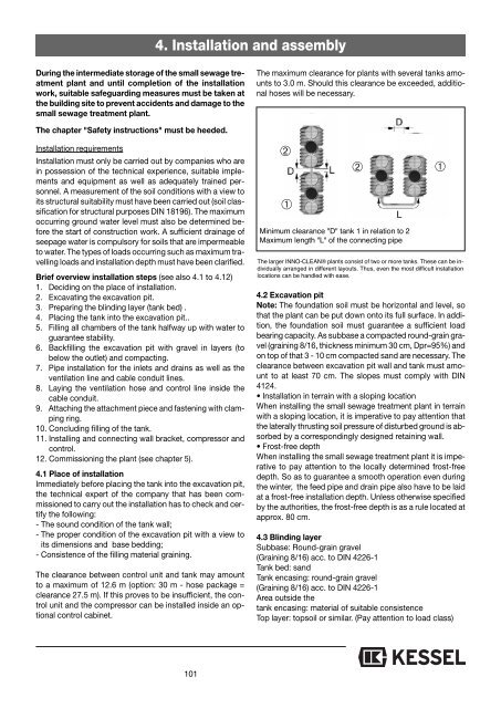
➁<br />
➀<br />
➁<br />
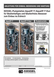
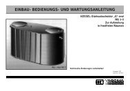
Minimum clearance "D" tank 1 in relation to 2<br />
Maximum length "L" of the connecting pipe<br />
➀<br />
The larger <strong>INNO</strong>-<strong>CLEAN®</strong> plants consist of two or more tanks. These can be individually<br />
arranged in different layouts. Thus, even the most difficult installation<br />
locations can be handled with ease.<br />
4.2 Excavation pit<br />
Note: The foundation soil must be horizontal and level, so<br />
that the plant can be put down onto its full surface. In addition,<br />
the foundation soil must guarantee a sufficient load<br />
bearing capacity. As subbase a compacted round-grain gravel<br />
(graining 8/16, thickness minimum 30 cm, Dpr=95%) and<br />
on top of that 3 - 10 cm compacted sand are necessary. The<br />
clearance between excavation pit wall and tank must amount<br />
to at least 70 cm. The slopes must comply with DIN<br />
4124.<br />
• Installation in terrain with a sloping location<br />
When installing the small sewage treatment plant in terrain<br />
with a sloping location, it is imperative to pay attention that<br />
the laterally thrusting soil pressure of disturbed ground is absorbed<br />
by a correspondingly designed retaining wall.<br />
• Frost-free depth<br />
When installing the small sewage treatment plant it is imperative<br />
to pay attention to the locally determined frost-free<br />
depth. So as to guarantee a smooth operation even during<br />
the winter, the feed pipe and drain pipe also have to be laid<br />
at a frost-free installation depth. Unless otherwise specified<br />
by the authorities, the frost-free depth is as a rule located at<br />
approx. 80 cm.<br />
4.3 Blinding layer<br />
Subbase: Round-grain gravel<br />
(Graining 8/16) acc. to DIN 4226-1<br />
Tank bed: sand<br />
Tank encasing: round-grain gravel<br />
(Graining 8/16) acc. to DIN 4226-1<br />
Area outside the<br />
tank encasing: material of suitable consistence<br />
Top layer: topsoil or similar. (Pay attention to load class)<br />
101