KESSEL-Kleinkläranlagen INNO-CLEAN® - Kessel Design
KESSEL-Kleinkläranlagen INNO-CLEAN® - Kessel Design
KESSEL-Kleinkläranlagen INNO-CLEAN® - Kessel Design

Create successful ePaper yourself
Turn your PDF publications into a flip-book with our unique Google optimized e-Paper software.
ANLEITUNG FÜR EINBAU, BEDIENUNG UND WARTUNG<br />
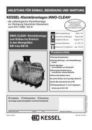
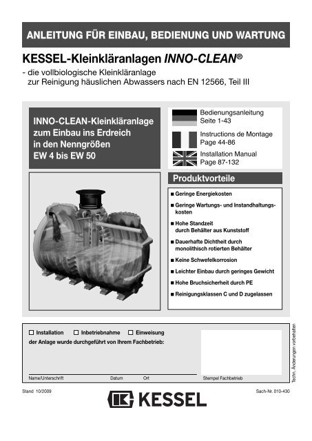
<strong>KESSEL</strong>-<strong>Kleinkläranlagen</strong> <strong>INNO</strong>-CLEAN ®<br />
- die vollbiologische Kleinkläranlage<br />
zur Reinigung häuslichen Abwassers nach EN 12566, Teil III<br />
<strong>INNO</strong>-CLEAN-Kleinkläranlage<br />
zum Einbau ins Erdreich<br />
in den Nenngrößen<br />
EW 4 bis EW 50<br />
Bedienungsanleitung<br />
Seite 1-43<br />
Instructions de Montage<br />
Page 44-86<br />
Installation Manual<br />
Page 87-132<br />
Produktvorteile<br />
Geringe Energiekosten<br />
Geringe Wartungs- und Instandhaltungskosten<br />
Hohe Standzeit<br />
durch Behälter aus Kunststoff<br />
Dauerhafte Dichtheit durch<br />
monolithisch rotierten Behälter<br />
Keine Schwefelkorrosion<br />
Leichter Einbau durch geringes Gewicht<br />
Hohe Bruchsicherheit durch PE<br />
Reinigungsklassen C und D zugelassen<br />
Installation Inbetriebnahme Einweisung<br />
der Anlage wurde durchgeführt von Ihrem Fachbetrieb:<br />
Name/Unterschrift Datum Ort<br />
Stempel Fachbetrieb<br />
Techn. Änderungen vorbehalten<br />
Stand 10/2009<br />
Sach-Nr. 010-430
1. Sicherheitshinweise<br />
Achtung! Erstickungsgefahr beim Betreten der Anlage<br />
Das Personal für Montage, Bedienung, Wartung und Reparatur muss die entsprechende Qualifikation<br />
für diese Arbeiten aufweisen.<br />
Der Verantwortungsbereich, die Zuständigkeit und die Überwachung des Personals müssen durch<br />
den Betreiber genau geregelt sein.<br />
Die Betriebssicherheit der gelieferten Anlage ist nur bei bestimmungsgemäßer Verwendung gewährleistet.<br />
Die Grenzwerte der technischen Daten dürfen auf keinen Fall überschritten werden.<br />
Diese Anlage enthält elektrische Spannungen und steuert mechanische Anlagenteile. Bei Nichtbeachtung<br />
der Bedienungsanleitung können erhebliche Sachschäden, Körperverletzungen oder tödliche<br />
Unfälle die Folge sein.<br />
Bei Montage, Bedienung, Wartung und Reparatur der Anlage sind die Unfallverhütungsvorschriften,<br />
die in Frage kommenden DIN- und VDE-Normen und Richtlinien zu beachten.<br />
Dies sind u.a.:<br />
• „Unfallverhütungsvorschriften - Bauarbeiten“ BGV C22 bisher VBG 37<br />
• „Baugruben und Gräben, Böschungen, Arbeitsraumbreite, Verbau“ DIN 4124<br />
• „Verlegung und Prüfung von Abwasserleitungen und -kanälen“ DIN EN 1610<br />
• „Richtlinien für Arbeiten in Behältern und engen Räumen“ BGR 117 bisher ZH1/77<br />
Die Abdeckung der Kleinkläranlage muss gegen unbefugtes Öffnen (insbesondere durch Kinder)<br />
auch während der Arbeitspausen ausreichend gesichert sein.<br />
Warnung !<br />
Die Anlage besteht aus mehreren Komponenten. Beachten Sie deshalb die einzelnen Kapitel in der<br />
Bedienungsanleitung. Bei jeder Montage, Wartung, Inspektion und Reparatur an einer der Komponenten<br />
ist immer die Gesamtanlage durch ziehen des Netzsteckers an der Steuereinheit außer Betrieb<br />
zu setzen und gegen Wiedereinschalten zu sichern. Stellen Sie sicher, dass der Zufluss von Abwasser<br />
während der Montage unterbrochen ist.<br />
Das Steuergerät steht unter Spannung und darf nicht geöffnet werden.<br />
Nur Elektrofachkräfte dürfen Arbeiten an elektrischen Einrichtungen durchführen.<br />
Der Begriff Elektrofachkraft ist in der VDE 0105 definiert.<br />
Arbeiten am Verdichter, die über die im Kapitel Inspektion und Wartung beschriebenen Tätigkeiten<br />
hinausgehen, sind unzulässig.<br />
Es ist sicherzustellen, dass sich die Elektrokabel sowie alle anderen elektrischen Anlagenteile in<br />
einem einwandfreien Zustand befinden. Bei Beschädigung darf die Anlage auf keinen Fall in Betrieb<br />
genommen werden.<br />
Achtung !<br />
Umbau oder Veränderungen der Anlage sind nur in Absprache mit dem Hersteller zu tätigen. Originalersatzteile<br />
und vom Hersteller zugelassenes Zubehör dienen der Sicherheit. Die Verwendung anderer<br />
Teile kann die Haftung für die daraus entstehenden Folgen aufheben.<br />
2
Inhaltsverzeichnis<br />
1. Sicherheitshinweise .......... .............................................................................................. Seite 2<br />
2. Allgemeines 2.1 Einsatzbereich ........................................................................ Seite 5<br />
2.2 Anlagenbeschreibung .............................................................. Seite 5<br />
2.3 Anlagenkonfiguration .............................................................. Seite 6<br />
2.4 Maße und Nutzvolumen .......................................................... Seite 11<br />
2.5 Funktionsbeschreibung ........................................................... Seite 12<br />
3. Verpackung, Transport 3.1 Verpackung.............................................................................. Seite 14<br />
und Lagerung 3.2 Transport................................................................................. Seite 14<br />
3.3 Lagerung ................................................................................. Seite 14<br />
4. Einbau und Montage 4.1 Einbauort................................................................................. Seite 15<br />
4.2 Baugrube................................................................................. Seite 15<br />
4.3 Sauberkeitsschicht.................................................................. Seite 15<br />
4.4 Einsetzen ................................................................................ Seite 16<br />
4.5 Behälter befüllen..................................................................... Seite 16<br />
4.6 Verfüllung Baugrube................................................................ Seite 16<br />
4.7 Verrohrung .............................................................................. Seite 16<br />
4.8 Verlegung der Verbindungsleitungen...................................... Seite 17<br />
4.9 Montage der Aufsatzstücke..................................................... Seite 17<br />
4.10 Befüllen................................................................................... Seite 18<br />
4.11 Einbau Steuereinheit und Verdichter....................................... Seite 19<br />
5. Inbetriebnahme 5.1 Anlage in Betriebsbereitschaft setzen..................................... Seite 21<br />
5.2 Pflichten des Betreibers .......................................................... Seite 23<br />
5.3 Einweisung Kunde .................................................................. Seite 23<br />
6. Betrieb und Entsorgung 6.1 Betrieb..................................................................................... Seite 24<br />
6.2 Eigenkontrolle des Betreibers ................................................. Seite 24<br />
6.3 Was nicht in die biol. Kleinkläranlage gehört........................... Seite 25<br />
6.4 Entsorgung.............................................................................. Seite 26<br />
7. Wartung 7.1 Vorklärung und Belebung........................................................ Seite 27<br />
7.2 Verdichter ................................................................................ Seite 27<br />
8. Steuerung der Kleinkläranlage 8.1 Systemmenü........................................................................... Seite 30<br />
8.2 Informationsmenü................................................................... Seite 30<br />
8.3 Wartungsmenü........................................................................ Seite 30<br />
9. Störungen und Abhilfemaßnahmen ............................................. ................................................... Seite 33<br />
10. Gewährleistung ..... ................................................................................................. Seite 36<br />
11. Anlagenpass und Werkabnahme ....................................................................................................... Seite 47<br />
12. Konformitätserklärung ....................................................................................................... Seite 38<br />
13. Betriebstagebuch ....................................................................................................... Seite 39<br />
14. Wartungscheckliste ....................................................................................................... Seite 40<br />
15. Technische Daten ....................................................................................................... Seite 41<br />
16. Übergabeprotokoll ....................................................................................................... Seite 43<br />
3
Sehr geehrter Kunde,<br />
wir freuen uns, dass Sie sich für ein Produkt von <strong>KESSEL</strong> entschieden haben.<br />
Die gesamte Anlage wurde vor Verlassen des Werkes einer strengen Qualitätskontrolle unterzogen. Prüfen Sie bitte dennoch<br />
sofort, ob die Anlage vollständig und unbeschädigt bei Ihnen angeliefert wurde. Im Falle eines Transportschadens<br />
beachten Sie bitte die Anweisungen in Kapitel „Gewährleistung“ dieser Anleitung.<br />
Diese Einbau-, Bedienungs- und Wartungsanleitung enthält wichtige Hinweise, die bei Montage, Bedienung, Wartung und<br />
Reparatur zu beachten sind. Vor allen Arbeiten an der Anlage müssen der Betreiber sowie das zuständige Fachpersonal<br />
diese Anleitung sorgfältig lesen und befolgen.<br />
<strong>KESSEL</strong> GmbH<br />
4
2. Allgemeines<br />
2.1 Einsatzbereich<br />
<strong>INNO</strong>-CLEAN ® , die Kleinkläranlage von <strong>KESSEL</strong>, ist eine<br />
Reinigungsanlage für häusliche Abwässer nach EN 12566,<br />
Teil III. Für Niederschlagsabwässer, Abwässer aus der Tierhaltung<br />
sowie Schwimmbadabwässer ist diese Anlage nicht<br />
vorgesehen. In einem biologischen Verfahren, reinigt diese<br />
Kleinkläranlage häusliches Abwasser und passt sich automatisch<br />
den anfallenden Mengen an. Das Abwasser wird je<br />
nach Anlagengröße in einem oder mehreren Kunststoffbehältern<br />
gesammelt und gereinigt. Dieser Behälter ist zum<br />
Verbau im Erdreich vorgesehen. Die Belüftung und Umwälzung<br />
wird von einem Verdichter bereitgestellt und durch<br />
eine Steuereinheit vollautomatisch geregelt. Der Verdichter<br />
und die Steuerung sind zum freien Einbau in frostgeschützten,<br />
überflutungssicheren und trockenen Räumen vorgesehen.<br />
Die Zuleitung muß rückstaufrei an die <strong>INNO</strong>-CLEAN ®<br />
angeschlossen werden. Zusätzlich zu der Kleinkläranlage<br />
muss für eine angemessene Abwasserableitung nach ATV-<br />
DVWK-A138 gesorgt werden. Weiterhin ist in jedem Fall die<br />
Kommune, der Landkreis oder die untere Wasserbehörde<br />
für eine Genehmigung zur Errichtung und den Betrieb der<br />
Anlage zuständig.<br />
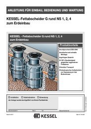
2.2 Anlagenbeschreibung<br />
<br />
<br />
<br />
<br />
<br />
<br />
<br />
<br />
<br />
<br />
<strong>KESSEL</strong>-<strong>INNO</strong>-CLEAN ® besteht aus zwei Hauptsegmenten.<br />
Innerhalb eines frostfreien, überflutungssicheren und<br />
trockenen Raumes befindet sich die Steuereinheit; der<br />
Kunststoffbehälter, in dem der Klärungsprozess stattfindet,<br />
wird außerhalb des Gebäudes im Erdreich verbaut.<br />
Steuereinheit (Steuerung und Verdichter)<br />
Zulauf<br />
Vorklärkammer<br />
Belebungskammer<br />
Belüfterkerze<br />
Sickerschacht (optional)<br />
Ventilblock<br />
Klärturm mit integriertem Probenahmebehälter,<br />
Luftheber und Ablauf<br />
Kabelleerrohr<br />
Lüftungsleitung<br />
5
2. Allgemeines<br />
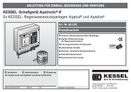
2.3 Anlagenkonfiguration<br />
Seitenansicht<br />
Behälter EW 4 - 6<br />
Nutzvolumen 4800 l<br />
Seitenansicht<br />
Behälter EW 8 -10<br />
Nutzvolumen 7600 l<br />
Frontansicht<br />
6
Anlagenkonfiguration EW 4, EW 6, EW 8 und EW 10<br />
2. Allgemeines<br />
7
2. Allgemeines<br />
Anlagenkonfiguration EW 12, EW 14, EW 16 und EW 20<br />
8
2. Allgemeines<br />
Anlagenkonfiguration EW 22 bis EW 30<br />
9
2. Allgemeines<br />
Anlagenkonfiguration EW 30 bis EW 50<br />
10
2. Allgemeines<br />
2.4 Maße und Nutzvolumen<br />
Kleinkläranlage Innoclean Klasse "C", mit Abdeckung Kl. A/B, tagwasserdicht und unverriegelt<br />
Einwohnergleichwert<br />
(EW)<br />
Artikelnummer Reinigungsklasse<br />
Behälter<br />
Zu-/Ablauf<br />
(DN)<br />
Gesamtvolumen<br />
(l)<br />
L<br />
(mm)<br />
B<br />
(mm)<br />
T<br />
(mm)<br />
T EÜ<br />
(mm)<br />
GW<br />
(mm)<br />
h2<br />
(mm)<br />
h1<br />
(mm)<br />
h leer<br />
(mm)<br />
Gewicht<br />
(ca. kg)<br />
C D Gesamt Behälter 1 Behälter 2 Behälter 3 Behälter 4 Behälter 5 Behälter 6 l1 l2 l3 b1=b2 min max<br />
4 97804 RC 97804 RD 1 150 4800 4800 2350 2000 800 1005 T-255 1775 1875 1775 2000 530<br />
6 97806 RC 97806 RD 1 150 4800 4800 2350 2000 800 1005 T-255 1775 1875 1775 2000 530<br />
8 97808 RC 97808 RD 1 150 7600 7600 3470 2000 800 1005 T-255 1775 1875 1775 2000 700<br />
10 97810 RC 97810 RD 1 150 7600 7600 3470 2000 800 1005 T-255 1775 1875 1775 2000 700<br />
12 97812 RC 97812 RD 2 150 9600 4800 4800 2350 2350 2000 800 1005 T-255 1775 1875 1775 2000 970<br />
14 97814 RC 97814 RD 2 150 12400 7600 4800 3470 2350 2000 800 1005 T-255 1775 1875 1775 2000 1130<br />
16 97816 RC 97816 RD 2 150 12400 7600 4800 3470 2350 2000 800 1005 T-255 1775 1875 1775 2000 1130<br />
18 97818 RC 97818 RD 2 150 15200 7600 7600 3470 3470 2000 800 1005 T-255 1775 1875 1775 2000 1300<br />
20 97820 RC 97820 RD 2 150 15200 7600 7600 3470 3470 2000 800 1005 T-255 1775 1875 1775 2000 1300<br />
22 97822 RC 97822 RD 3 150 18300 5350 7600 5350 2350 3470 2350 2000 800 1005 T-255 1775 1875 1775 2000 1430<br />
24 97824 RC 97824 RD 3 150 21000 8100 4800 8100 3470 2350 3470 2000 800 1005 T-255 1775 1875 1775 2000 1540<br />
26 97826 RC 97826 RD 3 150 21000 8100 4800 8100 3470 2350 3470 2000 800 1005 T-255 1775 1875 1775 2000 1540<br />
28 97828 RC 97828 RD 3 150 23800 8100 7600 8100 3470 3470 3470 2000 800 1005 T-255 1775 1875 1775 2000 1700<br />
30 97830 RC 97830 RD 3 150 23800 8100 7600 8100 3470 3470 3470 2000 800 1005 T-255 1775 1875 1775 2000 1700<br />
32 97832 RC 97832 RD 6 150 31000 5350 5350 4800 5350 4800 5350 2350 2350 2350 2000 800 1005 T-255 1775 1875 1775 2000 2620<br />
34 97834 RC 97834 RD 6 150 31000 5350 5350 4800 5350 4800 5350 2350 2350 2350 2000 800 1005 T-255 1775 1875 1775 2000 2620<br />
36 97836 RC 97836 RD 6 150 31000 5350 5350 4800 5350 4800 5350 2350 2350 2350 2000 800 1005 T-255 1775 1875 1775 2000 2620<br />
38 97838 RC 97838 RD 6 150 36600 5350 5350 7600 5350 7600 5350 2350 3470 2350 2000 800 1005 T-255 1775 1875 1775 2000 2950<br />
40 97840 RC 97840 RD 6 150 36600 5350 5350 7600 5350 7600 5350 2350 3470 2350 2000 800 1005 T-255 1775 1875 1775 2000 2950<br />
42 97842 RC 97842 RD 6 150 36600 5350 5350 7600 5350 7600 5350 2350 3470 2350 2000 800 1005 T-255 1775 1875 1775 2000 2950<br />
44 97844 RC 97844 RD 6 150 36600 5350 5350 7600 5350 7600 5350 2350 3470 2350 2000 800 1005 T-255 1775 1875 1775 2000 2950<br />
46 97846 RC 97846 RD 6 150 42000 8100 8100 4800 8100 4800 8100 3470 2350 3470 2000 800 1005 T-255 1775 1875 1775 2000 3150<br />
48 97848 RC 97848 RD 6 150 42000 8100 8100 4800 8100 4800 8100 3470 2350 3470 2000 800 1005 T-255 1775 1875 1775 2000 3150<br />
50 97850 RC 97850 RD 6 150 42000 8100 8100 4800 8100 4800 8100 3470 2350 3470 2000 800 1005 T-255 1775 1875 1775 2000 3150<br />
11
2. Allgemeines<br />
2.5 Funktionsbeschreibung<br />
Der Klärprozess wird vollautomatisch von<br />
der Steuereinheit geregelt. Ein Klärzyklus<br />
dauert ca. 8 Stunden und wird durch<br />
Abführen des geklärten Wassers beendet.<br />
Der Klärungsprozess basiert auf Mikroorganismen,<br />
die während der Behandlungsphase<br />
das Abwasser reinigen.<br />
1. Einleitung des Schwarzwassers<br />
(gesamtes häusliches Abwasser)<br />
Sämtliches häusliches Abwasser gelangt<br />
in die Vorklärkammer. Dort sinken die<br />
Schwerteile zum Boden ab und bilden eine<br />
Schlammschicht. Der Abwasserschlamm<br />
verbleibt in der Vorklärkammer, verdichtet<br />
sich und muss bei Erreichen der maximalen<br />
Aufnahmekapazität entsorgt werden.<br />
2. Füllen der Belebungskammer<br />
(Beschickung)<br />
Die Belebungskammer wird mit dem Abwasser<br />
aus der Vorklärkammer befüllt.<br />
Über den Beschickungsheber wird ein definiertes<br />
Abwasservolumen aus der Vorklärkammer<br />
in die Belebungskammer geführt.<br />
3. Behandlungsphase des Abwassers<br />
(Normal-, Spar- und Urlaubsphase)<br />
In der Belebungskammer wird das Abwasser<br />
mit kurzen Belüfterstößen (Membranrohrbelüfter)<br />
verwirbelt. Durch eine phasenweise<br />
Belüftung gelangt Sauerstoff in<br />
das Abwasser und Mikroorganismen erhalten<br />
Sauerstoff für den Nährstoffabbau.<br />
Dabei bildet sich Belebtschlamm. Der<br />
Stoffwechsel der Mikroorganismen reinigt<br />
das Abwasser.<br />
Die Behandlungsphase dauert in der Regel<br />
ca. sechs Stunden. Darüber hinaus reguliert<br />
sich die Anlage gemäß ihrer Beschickung.<br />
Die Abwasserbehandlung läuft<br />
dann im Rahmen der “Normalphase”, der<br />
“Sparphase” oder der “Urlaubsphase” ab.<br />
(siehe Punkt 6.1)<br />
12
2. Allgemeines<br />
4. Absetzphase<br />
Nach der Behandlungsphase folgt eine<br />
zweistündige Absetzphase. Alle in dem Abwasser<br />
enthaltenen Feststoffe, sowie der<br />
Belebtschlamm setzen sich am Beckenboden<br />
ab somit bildet sich im oberen Bereich<br />
eine Klarwasserschicht und am Boden eine<br />
Schlammschicht aus Mikroorganismen.<br />
5. Abziehen des Klarwassers<br />
(Klarwasserabzug)<br />
Oberhalb dieser Schlammschicht verbleibt<br />
nun gesäubertes Wasser das über den<br />
Luftheber für den Klarwasserabzug in die<br />
Vorflut oder Versickerung geführt wird.<br />
6. Rückpumpen des Belebtschlamms<br />
(Schlammabzug)<br />
Überschüssiger Belebtschlamm wird in die<br />
Vorklärung zurückgehoben.<br />
13
3. Verpackung, Transport und Lagerung<br />
Das Kapitel Sicherheitshinweise ist zu beachten!<br />
3.1 Verpackung<br />
Eine Verpackung der Behälter zum Zwecke des Transports<br />
bzw. der Lagerung ist bei Beachtung der nachfolgenden<br />
Punkte nicht notwendig.<br />
Hinweis: Der Eintrag von Fremdkörpern (Schmutz, Staub<br />
etc.) während der Verbauphase in die Kläranlage ist zu vermeiden.<br />
Ggf. sind an allen Öffnungen Abdeckungen anzubringen.<br />
3.2 Transport<br />
• Der Transport ist nur von solchen Firmen durchzuführen,<br />
die über fachliche Erfahrungen, geeignete Geräte, Einrichtungen<br />
und Transportmittel, sowie ausreichend geschultes<br />
Personal verfügen.<br />
• Die Behälter müssen so transportiert werden, daß sie nicht<br />
unzulässig belastet werden und dass eine Lageveränderung<br />
während des Transports ausgeschlossen ist. Im Falle<br />
einer Verspannung ist diese so vorzunehmen, dass eine<br />
Beschädigung der Behälter ausgeschlossen ist (z.B. Verwendung<br />
von Gewebe- oder Schlaufengurten). Die Verwendung<br />
von Drahtseilen oder Ketten ist nicht zulässig.<br />
• Die Behälter sind gegen unzulässige Lageveränderungen<br />
während der Beförderung zu sichern. Durch die Art der Befestigung<br />
dürfen die Behälter nicht beschädigt werden.<br />
3.3 Lagerung<br />
Sollte eine Lagerung der Behälter vor dem Einbau erforderlich<br />
sein, so darf diese nur kurzzeitig und auf ebenem, von<br />
scharfkantigen Gegenständen befreitem Untergrund geschehen.<br />
Bei Lagerung im Freien sind die Behälter gegen<br />
Beschädigung, Sturmeinwirkung und Verschmutzung zu<br />
schützen.<br />
• Beim Abheben, Verfahren und Absetzen der Behälter müssen<br />
stoßartige Beanspruchungen vermieden werden.<br />
Kommt ein Gabelstapler zum Einsatz, müssen während<br />
der Fahrt mit dem Gabelstapler die Behälter gesichert werden.<br />
Ein Rollen oder Schleifen der Behälter über den Untergrund<br />
ist nicht zulässig.<br />
14
4. Einbau und Montage<br />
Während der Zwischenlagerung der Kleinkläranlage<br />
sowie bis zum Abschluss der Einbauarbeiten, müssen<br />
an der Baustelle geeignete Sicherungsmaßnahmen getroffen<br />
werden, um Unfälle und Beschädigungen der<br />
Kleinkläranlage zu verhindern.<br />
Das Kapitel Sicherheitshinweise ist zu beachten.<br />
Einbauvoraussetzungen<br />
Der Einbau ist nur von solchen Firmen durchzuführen, die<br />
über fachliche Erfahrungen, geeignete Geräte und Einrichtungen<br />
sowie ausreichend geschultes Personal verfügen.<br />
Eine Erfassung der Bodenbeschaffenheit im Hinblick auf die<br />
bautechnische Eignung muss vorgenommen worden sein<br />
(Bodenklassifikation für bautechnische Zwecke DIN 18196).<br />
Der maximal auftretende Grundwasserstand muss ebenso<br />
vor Beginn der Bauarbeiten festgestellt werden. Eine ausreichende<br />
Ableitung (Drainage) von Sickerwässern ist bei<br />
wasserundurchlässigen Böden zwingend notwendig. Die<br />
auftretenden Belastungsarten wie max. Verkehrslasten und<br />
Einbautiefe müssen abgeklärt sein.<br />
Kurzübersicht Einbauschritte (siehe auch 4.1 bis 4.12)<br />
1. Einbauort festlegen.<br />
2. Baugrube ausheben.<br />
3. Sauberkeitsschicht (Behälterbett) erstellen.<br />
4. Behälter in die Baugrube einsetzen.<br />
5. Behälter in allen Kammern bis zur Hälfte mit Wasser befüllen,<br />
um Standsicherheit zu gewährleisten.<br />
6. Baugrube mit Kies (bis unter den Auslauf) lagenweise<br />
verfüllen und verdichten.<br />
7. Verrohrung der Zu- und Abläufe, sowie der Lüftungsleitung<br />
und Kabelleerrohrleitung.<br />
8. Belüftungsschlauch und Steuerleitung im Kabelleerrohr<br />
verlegen.<br />
9. Aufsatzstück aufsetzen und mit Klemmring fixieren.<br />
10. Abschließende Befüllung des Behälters.<br />
11. Wandkonsole, Verdichter und Steuerung montieren und<br />
anschließen.<br />
12. Inbetriebnahme der Anlage (siehe Kapitel 5).<br />
4.1 Einbauort<br />
Unmittelbar vor dem Einbringen des Behälters in die Baugrube<br />
hat der Sachkundige der mit dem Einbau beauftragten<br />
Firma folgendes zu prüfen und zu bescheinigen:<br />
- Die Unversehrtheit der Behälterwand;<br />
- den ordnungsgemäßen Zustand der Baugrube, insbesondere<br />
hinsichtlich der Abmessungen und Sohlenbettung;<br />
- Beschaffenheit der Körnung des Verfüllmaterials.<br />
Die Distanz zwischen Steuereinheit und Behälter darf maximal<br />
12,5 m (Option: 30 m - Schlauchpaket = Distanz 27,5<br />
m) betragen. Sollte dies nicht ausreichen, so kann die<br />
Steuereinheit und der Verdichter in einem optionalen Schaltschrank<br />
installiert werden.<br />
Der max. Abstand bei Anlagen mit mehreren Behältern beträgt<br />
3,0 m. Sollten Sie diesen Abstand überschreiten, so<br />
sind zusätzliche Schläuche notwendig.<br />
4.2 Baugrube<br />
➁<br />
➀<br />
➁<br />
➀<br />
Die größeren <strong>INNO</strong>-CLEAN ® -Anlagen bestehen aus zwei oder mehr Behältern.<br />
Diese lassen sich individuell in verschiedenen Varianten anordnen. So können<br />
schwierigste Einbausituationen leicht gemacht werden.<br />
Hinweis: Bei Mehrbehälteranlagen eine Baugrube für alle<br />
Behälter ausheben!<br />
Der Baugrund muss waagerecht und eben sein, um die Anlage<br />
vollflächig aufstellen zu können. Außerdem muss der<br />
Baugrund eine ausreichende Tragfähigkeit gewährleisten.<br />
Als Unterbau ist ein verdichteter Rundkornkies (Körnung<br />
8/16, Dicke mind. 30 cm, Dpr=95%) und darauf 3 - 10 cm<br />
verdichteter Sand notwendig. Der Abstand zwischen Baugrubenwand<br />
und Behälter muss mindestens 70 cm betragen.<br />
Die Böschungen müssen der DIN 4124 entsprechen.<br />
• Einbau im Gelände mit Hanglage<br />
Beim Einbau der Kleinkläranlage in ein Gelände mit Hanglage<br />
ist unbedingt darauf zu achten, dass der seitlich schiebende<br />
Erddruck bei nicht gewachsenem Boden durch eine<br />
entsprechend ausgelegte Stützmauer abgefangen wird.<br />
• Frostfreie Tiefe<br />
Beachten Sie beim Einbau der Kleinkläranlage unbedingt<br />
die örtlich festgelegte frostfreie Tiefe. Um auch im Winter<br />
einen reibungslosen Betrieb zu gewährleisten, ist beim<br />
Einbau ebenso die Zu- und Ablaufleitung in frostfreier<br />
Einbautiefe zu verlegen. In aller Regel liegt die frostfreie<br />
Tiefe, wenn nicht anders durch die Behörde angegeben, bei<br />
ca. 80 cm.<br />
4.3 Sauberkeitsschicht<br />
Unterbau: Rundkornkies<br />
(Körnung 8/16) nach DIN 4226-1<br />
Behälterbett: Sand<br />
Behälterumhüllung: Rundkornkies<br />
(Körnung 8/16) nach DIN 4226-1<br />
Bereich außerhalb<br />
Behälterumhüllung: Material geeigneter Beschaffenheit<br />
Deckschicht: Humus o.ä. (Belastungsklasse beachten)<br />
15
4. Einbau und Montage<br />
<br />
<br />
<br />
≤ 20cm<br />
≤ 30cm<br />
≤ 30cm<br />
≤ 30cm<br />
≥ 50cm<br />
<br />
≥ 50cm<br />
≤ 30cm<br />
≤ 30cm<br />
≤ 30cm<br />
≤ 30cm<br />
≤ 30cm<br />
β nach<br />
DIN 4124<br />
<br />
<br />
≤ 30cm<br />
3-10cm<br />
≥ 30cm<br />
≥ 70cm<br />
Unterbau: Rundkornkies (max. Körnung 8/16) nach<br />
DIN 4226-1 verdichtet mit Dpr=95%<br />
Behälterbett: verdichteter Sand<br />
Behälter<br />
Behälterumhüllung: Rundkornkies (max. Körnung<br />
≥ 70cm<br />
8/16) nach DIN 4226-1 verdichtet mit Dpr=95%<br />
Bereich außerhalb Behälterumhüllung:<br />
Material geeigneter Beschaffenheit<br />
Deckschicht: Humus, Straßenbelag, Beton o.ä.<br />
4.4 Einsetzen<br />
Der Behälter ist mit Hilfe einer geeigneten Vorrichtung<br />
stoßfrei in die Baugrube einzubringen und auf die Sohlenbettung<br />
aufzusetzen (siehe auch Kapitel „Transport“).<br />
Fließrichtung und Fließrichtungspfeile auf dem Behälter beachten!<br />
4.5 Behälter befüllen<br />
Behälter in beiden Kammern mit Klarwasser befüllen (ca. 80<br />
cm) um eine bessere Standfestigkeit zu erlangen.<br />
4.6 Verfüllung Baugrube<br />
Generell sollte das Befüllen des Behälters und die Verfüllung<br />
der Baugrube parallel ausgeführt werden. Die Verfüllung der<br />
Baugrube erfolgt bis Unterkante Zu- und Ablauf, sowie der<br />
Lüftungs- und Kabelleerrohrleitung. Die Behälterumhüllung<br />
muss in einer Breite von mindestens 50 cm hergestellt werden.<br />
Die einzelnen Lagen des Verfüllmaterials sollten nicht<br />
höher als 30 cm sein. Sie sind mit leichten Verdichtungsgeräten<br />
zu verdichten (mind. Dpr=95%). Eine Beschädigung<br />
der Behälterwand und eine Verlagerung der Behälter während<br />
und nach dem Einbau muss ausgeschlossen werden.<br />
4.7 Verrohrung<br />
Die Zu-/Ablaufleitungen, sowie Verbindungsleitungen sind<br />
frostfrei (siehe 4.2) zu verlegen und anzuschließen, sobald<br />
die Baugrube bis zur Unterkante der Zu- und Ablaufleitung<br />
verfüllt und verdichtet ist.<br />
Der Übergang von Fallleitungen in horizontale Leitungen ist<br />
mit zwei 45°-Bogenformstücken und einem mindestens 250<br />
mm langen Zwischenstück auszuführen. Vor dem Inno-<br />
Clean-Behälter ist eine Beruhigungsstrecke vorzusehen,<br />
deren Länge mindestens dem 10-fachen der Nennweite der<br />
Rohrleitung entspricht.<br />
• Kabelleerrohr<br />
Für die Leitungsverbindung zwischen Steuergerät/Kompressor<br />
und Ventilblock/Inno-Clean-Behälter muss ein Kabelleerrohr<br />
(KG-Rohr aus PVC-U in der Dimension DN 100)<br />
verlegt werden. Das Leerrohr sollte über seine gesamte<br />
Länge über ein stetiges Gefälle von ≥ 2° zum Behälter verfügen.<br />
Für die Durchführung durch die Gebäudewand empfiehlt<br />
<strong>KESSEL</strong> auf handelsübliche Wanddurchführungen<br />
zurück zu greifen (siehe Bild). Zur Abdichtung des Kabelleerrohres<br />
im Gebäude, sollte die Abdeckung von <strong>KESSEL</strong><br />
16
4. Einbau und Montage<br />
4.8 Verlegung der Verbindungsleitungen zur Steuereinheit<br />
(Belüftungsschlauch und Steuerleitung)<br />
Die Steuerleitung, sowie der Belüftungsschlauch sind zwischen<br />
Ventilblock und Steuereinheit im Kabelleerrohr zu verlegen<br />
( siehe Vorgehen).<br />
Luftschlauch zum Verdichter<br />
Betondecke<br />
Kellerwand<br />
Kabelleerrohrabdichtung<br />
Art. Nr. 97 711<br />
KG-Rohr DN 100<br />
Dichtung<br />
Art.-Nr. 860 116<br />
Dichtung für<br />
Rohrdurchführung<br />
Schnellverbinder<br />
Ventilblock<br />
Verriegelungsbügel<br />
Ventilblock<br />
Inno-Clean<br />
handelsübliche<br />
Wanddurchführung<br />
z. B.<br />
Fa. Steelter oder<br />
Fa. DOYMA<br />
DN 100<br />
Gefälle mind. 2°<br />
fallend zum Behälter<br />
Behälterwand<br />
Inno-Clean<br />
Adapterplatte<br />
(Kabelleerrohrabdichtung Art.-Nr. 97711) zum Schutz vor<br />
Geruchsbelästigungen eingesetzt werden.<br />
Richtungsänderungen sollten über Bogenformstücke mit<br />
maximal 30° Abwinkelung realisiert werden.<br />
Achtung: Alle Leitungen sollten temporär bis zum endgültigen<br />
Anschluß, mit Klebeband verschlossen werden, um<br />
Schmutzeintrag während des Durchschiebens zu vermeiden.<br />
Bemerkung:<br />
Die Behälter können im Bereich der Dome angebohrt werden,<br />
um zusätzliche Anschluß- und Lüftungsleitungen herzustellen.<br />
Hierzu sind Original-Bohrkronen und Rohrdurchführungsdichtungen<br />
von <strong>KESSEL</strong> zu verwenden (<strong>KESSEL</strong>-<br />
Bohrkronen DN 50 - DN 150, Art.-Nr. 50100,<br />
<strong>KESSEL</strong>-Rohrdurchführungsabdichtungen:<br />
DN 50 Art.-Nr. 850114<br />
DN 70 Art.-Nr. 850116<br />
DN 100 Art.-Nr. 850117<br />
DN 125 Art.-Nr. 850118<br />
DN 150 Art.-Nr. 850119)<br />
Die Bohrungen sollten auf möglichst planen Flächen erfolgen.<br />
Für eine optimale Abdichtung der Bohrung sollte der<br />
Abstand zwischen dem Rand der Bohrung und unebener<br />
Kontur mindestens 15 mm betragen, damit die Dichtung umlaufend<br />
gleichmäßig um die Bohrung anliegt.<br />
Lasche zum<br />
Einhängen der<br />
Steuerleitung<br />
Steuerleitung<br />
Luftschläuche zu den Drucklufthebern<br />
Vorgehen:<br />
- Öffnen des Verriegelungsbügels am Ventilblock im Behälter<br />
- Entnahme des Ventilblocks von der Adapterplatte<br />
- grauen Belüftungsschlauch und Steuerleitung durch das<br />
Kabelleerrohr ziehen<br />
- Belüftungsschlauch mittels Schnellverbinder am Ventilblock<br />
anschließen (siehe 4.11 Punkt 5)<br />
- Ventilblock auf Adapterplatte einsetzen<br />
- Achtung: Steuerleitung muss in vorgesehene Lasche eingeklipst<br />
werden (siehe Abb.) um ein korrektes Verriegeln<br />
mit der Adapterplatte zu gewährleisten.<br />
- Ventilblock auf korrekten Sitz prüfen und Verriegelungsbügel<br />
schließen<br />
4.9 Montage der Aufsatzstücke<br />
Zuerst die Dichtung (siehe Zeichnung 4.9) in die vorgesehene<br />
Sicke im Dom einlegen.<br />
• Entlüftung<br />
Die Be- und Entlüftung der Anlage erfolgt über eine Lüftungsleitung<br />
der Größe DN 100 und wird an der entsprechenden Öffnung<br />
am Dom angeschlossen. Eine zusätzliche Lüftungsleitung<br />
kann am Dom angeschlossen werden (siehe Abb. S. 5).<br />
Hierzu ist die entsprechende Bohrkrone und Rohrdurchführungsdichtung<br />
von <strong>KESSEL</strong> zu verwenden . <strong>KESSEL</strong> empfiehlt<br />
die Verwendung eines Aktivkohlefilters zur Vermeidung<br />
von Geruchsbelästigung.<br />
17
4. Einbau und Montage<br />
Die Dichtlippe soll auf der Innenseite des<br />
Ringes nach unten zeigen.<br />
Das teleskopische <strong>KESSEL</strong>-Aufsatzstück im unteren Bereich<br />
mit Gleitmittel einfetten und in die Behälteröffnung einstecken,<br />
in die gewünschte Position bringen und mittels<br />
Klemmring fixieren. Alternativ kann Gleitmittel auch auf den<br />
Dichtring aufgetragen werden. Mit Hilfe des vorhandenen<br />
Klemmringes kann nun das Aufsatzstück in der gewünschten<br />
Position (Ausrichtung an der Geländeoberkante) fixiert<br />
werden. Die Feinjustierung auf die endgültige Höhe erfolgt<br />
dann mittels der Stellschrauben. Bodenneigungen können<br />
durch das stufenlos höhenverstellbare und bis 5° neigbare<br />
Aufsatzstück ausgeglichen werden. Die mitgelieferten Aufkleber<br />
der “Innofanten” sind auf die gereinigte und trockene<br />
Innenfläche am Aufsatzstück anzubringen (siehe Bild).<br />
Wichtig: Der grüne “Innofant” ist auf die Zulaufseite zu kleben<br />
und der rote auf die Auslaufseite!<br />
Anschließend das Aufsatzstück ausreichend verfüllen und<br />
verdichten.<br />
Zulauf<br />
➔<br />
➔<br />
Auslauf<br />
4.10 Abschließende Befüllung des Behälters<br />
Vor dem Verfüllen nochmaliges Kontrollieren der Zu- und Ablaufleitung, sowie der Entlüftungsleitung und des Kabelleerrohrs.<br />
Das Aufsatzstück mit der Geländeoberkante abgleichen.<br />
18
4. Einbau und Montage<br />
<br />
<br />
Netzanschluss<br />
<br />
<br />
Verdichter<br />
Wandkonsole<br />
<br />
<br />
<br />
Steuergerät<br />
Netzanschluss Verdichter<br />
<br />
<br />
<br />
Anschlussbuchse für potentialfreien Kontakt<br />
Anschluss Ventilblock<br />
(inkl. Schwimmerschalter)<br />
Anschluss externer Signalgeber<br />
<br />
Druckluftanschluss Ventilblock<br />
Anschluss Druckluftsensor<br />
<br />
Winkelstück für<br />
Anschluss Druckluftschlauch<br />
Schnellverbinder<br />
4. 11 Einbau der Steuereinheit und des Verdichters<br />
Beachten Sie bitte, daß für die Anschlussleitungen vom<br />
Behälter zur Steuereinheit ein Kabelleerrohr (DN 100) verlegt<br />
werden muss (siehe 4.7).<br />
Allgemeine Hinweise<br />
ACHTUNG: <strong>KESSEL</strong> empfiehlt, für die Ausführung von<br />
elektrischen Anschlüssen, einen Fachbetrieb des Elektrohandwerks<br />
zu beauftragen. Nehmen sie die Anlage<br />
erst nach vollständigem Einbau in Betrieb. Während der<br />
Anschlussarbeiten darf die Anlage nicht ans Netz angeschlossen<br />
sein.<br />
Steuerung und Verdichter sind in einem frostgeschützten,<br />
überflutungssicheren und trockenen Raum zu montieren.<br />
Rückstausichere Montage beachten!<br />
Auf eine gute Belüftung des Raumes in dem der Verdichter<br />
aufgestellt wird ist zu achten. Eine ausreichende Luftzirkulation,<br />
insbesondere auch bei Geräten die innerhalb eines<br />
Außenschaltschrankes untergebracht werden sollen, ist zu<br />
achten, um den Verdichter vor Überhitzung zu schützen.<br />
Eine kühle Umgebungstemperatur sichert eine hohe Lebensdauer<br />
der Membranen und Ventile.<br />
Der Verdichter sollte nicht in staubiger Umgebung betrieben<br />
werden. Ein Überhitzen durch verstopfte Filter verkürzt die<br />
Lebensdauer der Membranen und Filter.<br />
Der Verdichter soll vor direkter Sonneneinstrahlung, Regen,<br />
Schnee und Frost geschützt sein. Die angesaugte Umgebungsluft<br />
muss frei von entflammbaren oder aggressiven<br />
Gasen oder Dämpfen sein.<br />
Die Schlauchleitung ist so kurz und so gerade wie möglich<br />
zwischen Steuerung und Behälter zu verlegen. Richtungsänderungen<br />
sind über lange Bögen anstatt engen Abwinkelungen<br />
zu realisieren.<br />
Der Verdichter ist oberhalb der Steuerung auf einem geeigneten<br />
Sockel oder einer Konsole zu platzieren, um evtl.<br />
Schäden zu vermeiden.<br />
Bei der Montage auf einer instabilen Unterlage können durch<br />
Vibrationen störende Geräusche auftreten.<br />
Der Verdichter ist horizontal zu montieren, um eine einseitige<br />
Belastung der Membranen und dadurch verkürzte Lebensdauer<br />
der Komponenten zu verhindern.<br />
Der Verdichter soll auf allen 4 Gummifüßen komplett aufstehen<br />
und soll nicht wackeln.<br />
19
4. Einbau und Montage<br />
Montage und Anschluß<br />
Die Wandkonsole ist mittels beider mitgelieferter<br />
Dübel und Schrauben waagerecht an der Wand zu<br />
fixieren.<br />
<br />
<br />
<br />
<br />
<br />
<br />
<br />
<br />
Das Steuergerät durch Lösen der vier stirnseitigen<br />
Kreuzschlitzschrauben öffnen und dessen Rückwand<br />
mit den mitgelieferten vier Kreuzschlitzschrauben an<br />
den vorgebohrten Stellen der Wandkonsole (unterhalb<br />
der Abstellfläche für den Verdichter) befestigen.<br />
Anschließend ist das Steuergerät wieder zu verschließen.<br />
Achtung: Darauf achten, dass das Gerät<br />
spannungsfrei ist (siehe Sicherheitshinweise S.2)<br />
Den Verdichter auf der Abstellfläche der Wandkonsole<br />
in die dafür vorgesehenen Vertiefungen stellen.<br />
Bitte beachten Sie, dass die Kontrolllampe nach<br />
vorne gerichtet und der elektrische Anschluss des<br />
Gerätes auf der rechten Seite des Gerätes ist. Der<br />
Netzstecker des Verdichters ist mit der Schuko-<br />
Kupplung am Schaltgerät zu verbinden.<br />
Bevor das Winkelstück für den Anschluss der Druckluftleitung<br />
an den Verdichter am Gerät angeschlossen<br />
wird, ist die mitgelieferte Metallhülse in den langen<br />
Schenkel des Winkelstückes einzuschieben. Anschließend<br />
erfolgt die Montage des Winkelstückes<br />
am Stutzen des Verdichters und dessen Fixierung<br />
mittels der Federklemme am Gerät.<br />
Abweichung bei den Verdichtergrößen EL 150/200/<br />
250: Entfernen Sie den Stutzen beim Verdichter und<br />
Schrauben Sie das mitgelieferte Winkelstück am Gewinde<br />
des Verdichters ein (Gewinde mit Teflonband<br />
o.ä. abdichten). Das Einbringen der Metallhülse entfällt<br />
bei diesen Verdichtergrößen.<br />
Den Schnellverbinder durch Drehen der Verschlusskappe um 60° nach links öffnen und das lange Ende des<br />
Winkelstückes bis zum Anschlag einschieben. Die Verschlusskappe durch Rechtsdrehung schließen.<br />
Der transparente Schlauch des Druckluftsensors ist mit dem Steuergerät an der dritten Buchse von links<br />
anzuschließen. Hierfür die schwarze Überwurfmutter lösen und den innenliegenden Klemmring entnehmen,<br />
danach die Überwurfmutter und den Klemmring auf den transparenten Schlauch aufschieben, anschl.<br />
Schlauch aufstecken. Zum Schluss schwarze Überwurfmutter handfest anschrauben.<br />
Für den Anschluss der Druckluftleitung aus dem Behälter ist der graue Belüftungsschlauch im Kabelleerrohr<br />
auf passende Länge zu kürzen und ohne Abwinkelungen mit dem Schnellverbinder am Verdichter zu<br />
fixieren. Achtung: Belüftungsschlauch locker, nicht auf Spannung verlegen.<br />
Das Anschlusskabel vom Ventilblock ist in die entsprechende Buchse am Steuergerät einzustecken und mit<br />
der Verschraubung zu fixieren.<br />
20
4. Einbau und Montage<br />
Optionale Anschlüsse am Schaltgerät:<br />
Achtung: Alle optionalen Anschlüsse sind nur durch Elektrofachkräfte durchzuführen.<br />
21
5. Inbetriebnahme<br />
<br />
<br />
Display/Anzeigenfeld<br />
Bewegungstasten/Richtungstasten<br />
für die Führung durch das Programm-Menü<br />
<br />
<br />
<br />
<br />
Bestätigungstaste/OK-Taste<br />
Zurücktaste/ESC-Taste<br />
Kontrolllampe für Betriebsbereitschaft<br />
Kontrolllampe für Störungsmeldung<br />
Netzabschlusskabel<br />
Netzanschluss für Verdichter<br />
Anschluss Druckluftsensor<br />
Anschlussmöglichkeiten<br />
für externen Signalgeber<br />
<br />
Anschlus für Ventilblock<br />
<br />
<br />
Anschlussbuchse für potentialfreien Kontakt<br />
Einweisung / Übergabe<br />
Das Kapitel Sicherheitshinweise ist zu beachten! (S.2)<br />
Hinweis: Die Netzleitung muss mit einem FI-Schutzautomaten<br />
ausgerüstet sein.<br />
Die Inbetriebnahme wird von einem Fachbetrieb oder einem<br />
<strong>KESSEL</strong>-Beauftragten durchgeführt (gegen Aufpreis).<br />
Folgende Personen sollten bei der Übergabe anwesend sein:<br />
- Abnahmeberechtigter des Bauherrn<br />
- Fachbetrieb<br />
Ferner empfehlen wir die Teilnahme des Bedienungspersonals/<br />
Betreibers, Entsorgungsunternehmens<br />
0.<br />
Systemstart<br />
Systemdiagnose<br />
0.1 Sprache<br />
deutsch<br />
französisch<br />
englisch<br />
Übersicht Einweisung:<br />
5. 1. Anlage in Betriebsbereitschaft setzen<br />
5. 2. Kontrolle der Anlage<br />
5. 3. Einweisung anhand der Einbau- und Bedienungsanleitung<br />
5. 4. Erstellung des Übergabeprotokolls. (siehe Kapitel 13)<br />
0.2 Datum/Uhrzeit<br />
0.3 Klassen<br />
C<br />
D<br />
Datum<br />
01.01.2009 Uhrzeit<br />
12:00<br />
Nach Beendigung der Einweisung ist die Anlage in betriebsbereiten<br />
Zustand zu setzen.<br />
5.1 Anlage in Betriebsbereitschaft setzen<br />
Die Anlage ist vor Inbetriebnahme vollständig zu reinigen<br />
(einschließlich Zu- und Abläufe); Fest- und Grobstoffe sind zu<br />
entfernen.<br />
Die Anlage ist bis zu einer Höhe von 1,20 m in beiden Kammern<br />
mit klarem Wasser zu befüllen. Netzstecker des Steuergerätes<br />
in die Steckdose stecken. Die Anlage initialisiert sich<br />
selbständig.<br />
1.5 Systeminfo<br />
Uhrzeit: 20:45<br />
Schwimmer: S1<br />
S2<br />
Ereignisse:<br />
Netzausfall<br />
Normalphase<br />
0.4 Nenngrößen<br />
EW4<br />
EW6<br />
EW8<br />
EW10<br />
…<br />
EW24<br />
22
5. Inbetriebnahme<br />
Bei der Erstinitialisierung der Anlage fragt das Steuergerät<br />
nach vier Grundeinstellungen. Im Display des<br />
Steuergerätes erscheint die Frage nach<br />
1. der Sprache für die Benutzerführung<br />
2. dem Datum und der Uhrzeit<br />
3. der gewünschten Reinigungsklasse C oder D<br />
4. der erforderlichen Nenngröße der Anlage.<br />
5.3. Einweisung des Kunden anhand der Einbauanleitung<br />
- Einbau- und Bedienungsanleitung mit Kunde durchgehen<br />
- Bedienung der Anlage (Erklären und Beschreiben)<br />
- Aufklärung des Kunden über die Pflichten des Betreibers<br />
(Entsorung, Wartung, Betrieb einer biologischen Kleinkläranlage,<br />
Betriebstagebuch)<br />
Durch Betätigen der Bewegungstasten / Richtungstasten<br />
kann die gewünschte Einstellung über einen Markierungsbalken<br />
gekennzeichnet werden und die Anschließende<br />
Betätigung der Bestätigungstaste hinterlegt die gewählte<br />
Einstellung im Systemspeicher. Sobald die 4 Voreinstellungen<br />
vorgenommen wurden, lädt das Steuergerät den Programmspeicher<br />
und geht selbständig in den Betriebsmodus.<br />
Die Anlage ist jetzt betriebsbereit.<br />
5.2 Pflichten des Betreibers<br />
Kontrolle<br />
- Transport- oder Montageschäden<br />
- bauliche Mängel<br />
- aller elektrischen und mechanischen Komponenenten auf<br />
Sitz und Funktion prüfen<br />
- Schwimmerfunktion<br />
- Schlauchanschlüsse<br />
- Prüfung der Leitungsverbindungen<br />
- der Heber (siehe Punkt 8)<br />
- Belüfterkerze<br />
23
6. Betrieb und Entsorgung<br />
6.1 Betrieb<br />
Nach Inbetriebnahme der Anlage bildet sich nach 3-6 Monaten<br />
eine aktive Belebtschlammschicht mit Mikroorganismen<br />
in der Belebungskammer. Mikroorganismen müssen<br />
dieser Anlage nicht zugeführt werden. Eine Zuführung von<br />
Belebtschlamm aus dem nächstgelegenen Klärwerk erachten<br />
wir jedoch als sinnvoll. Wichtig: Belebtschlamm ausschließlich<br />
in die Belebungskammer geben!<br />
Zum reibungslosen Betrieb sind die Wartungsintervalle unbedingt<br />
einzuhalten. Die rechtzeitige Entleerung der Vorklärkammer<br />
muss gewährleistet sein.<br />
Der Betrieb der Kleinkläranlage läuft vollautomatisch ab. Im<br />
Einzelnen sind dies drei Phasen, die “Normal”-, “Spar”-,<br />
und “Urlaubsphase”. Diese unterscheiden sich bezüglich<br />
ihrer Belüftungszeit und Menge. Die eigentliche Klärung findet<br />
in der Normalphase (6 Stunden) statt.<br />
Bei nicht ausreichender Beschickung der Anlage (zu geringer<br />
Schmutzwasserzulauf) geht diese selbständig in die<br />
“Sparphase” (2 Stunden) über. In dieser Phase wird aufgrund<br />
der geringeren Abwassermenge die Belüftungszeit reduziert,<br />
um ein “aushungern” der adaptierten Mikroorganismen<br />
zu verhindern. Bei längerem Verbleib in der “Sparphase”<br />
(8 Stunden) schaltet sich automatisch die “Urlaubsphase”<br />
ein.<br />
Die “Urlaubsphase” zeichnet sich durch eine noch geringere<br />
Sauerstoffzufuhr aus. Ergänzend dazu wird am Ende der<br />
Urlaubsphase eine definierte Schlammmenge von der Belebtkammer<br />
in die Vorklärung gefördert. Dies ermöglicht<br />
beim nächsten Beschicken eine gewisse Nährstoffzufuhr in<br />
die Belebung. Dies trägt zur Biologieerhaltung bei längerem<br />
Stillstand bei.<br />
Sobald in der Vorklärkammer ausreichend Wasser vorhanden<br />
ist, dass der Schwimmer beim anschließenden Beschicken<br />
eingeschaltet wird, geht die Anlage automatisch in<br />
die Normalphase über.<br />
Diese Anpassung an unterschiedliche Abwassermengen<br />
wird automatisch von der Steuerung geregelt. Die entsprechende<br />
Phase wird am Schaltgerät angezeigt. Eine allgemeine<br />
Übersicht über die entsprechenden Phasen und Zyklen<br />
finden Sie im Kapitel 2.5.<br />
Wenn Sie sich an nachfolgende Empfehlungen halten, können<br />
Sie unnötige Reparaturkosten vermeiden und die Lebensdauer<br />
Ihrer Anlage erhöhen:<br />
• Die Anlage muss ständig eingeschaltet bleiben, auch<br />
während Sie sich im Urlaub befinden.<br />
• Fremdwasser, wie Regen-, Grund-, Schwimmbad- und<br />
Aquarienwasser darf nicht eingeleitet werden.<br />
• Bei Haushaltsreinigern beachten Sie bitte, dass diese keine<br />
sauren oder alkalischen Reaktionen zeigen. Wir empfehlen<br />
biologische abbaubare Reiniger und Waschmittel.<br />
• Die Deckel der Anlage müssen sich öffnen lassen.<br />
• Sorgen Sie dafür, dass die Anlage regelmäßig durch eine<br />
Fachfirma gewartet wird.<br />
• Nur die Vorklärung muss regelmäßig (ca. alle 12-24 Monate)<br />
durch ein Entsorgungsunternehmen entschlammt<br />
werden! Nach Rücksprache mit den zuständigen Wasserbehörden<br />
und Abschluss eines Wartungsvertrages kann<br />
dies aber auch ggf. bedarfsgerecht erfolgen.<br />
Hinweis: Bei Außerbetriebnahme muss sicher gestellt werden,<br />
dass die Anlage weiterhin gefüllt bleibt.<br />
Unbedingt beachten:<br />
Sie können weiterhin alle Reinigungs- und Waschmittel<br />
benutzen - aber bitte die Dosierungsvorschriften<br />
der Hersteller beachten!<br />
Auch verschiedene Rohrreiniger sind, wenn die Dosierung<br />
nach Herstellerangaben eingehalten wird,<br />
verwendbar.<br />
Allerdings sterben bei jeder Einleitung dieser Reinigungsmittel<br />
eine Anzahl an Bakterien ab. Wenn möglich,<br />
bitte auf biologisch abbaubare Reiniger zurückgreifen<br />
und auf die Verwendung von Rohrreinigungsmitteln<br />
verzichten (siehe 6.3).<br />
6.2 Eigenkontrolle des Betreibers<br />
Als Betreiber der Kläranlage haben Sie gegenüber der Wasserbehörde<br />
die Pflicht, für einen reibungslosen Betrieb der<br />
Anlage zu sorgen. Betriebsstörungen an biologischen <strong>Kleinkläranlagen</strong><br />
wirken sich negativ auf die Ablaufqualität des<br />
gereinigten Wassers aus. Diese müssen daher umgehend<br />
erkannt und durch Sie selbst oder einen qualifizierten Wartungsbetrieb<br />
beseitigt werden. Um die Eigenkontrollen zu<br />
dokumentieren, sind Sie verpflichtet, ein Betriebstagebuch<br />
zu führen. Am Ende dieses Handbuches finden Sie eine Kopiervorlage,<br />
die alle notwendigen Vorgaben enthält.<br />
Die Wasserbehörde kann Einsicht in dieses Betriebstagebuch<br />
verlangen. Im Einzelnen sind Sie dazu aufgefordert,<br />
folgende Kontrollen regelmäßig durchzuführen:<br />
Monatliche Kontrollen<br />
• An der Steuerung: Übertragen der Betriebszeiten vom Display<br />
ins Betriebstagebuch<br />
• An der Vorklärung: Kontrolle von Schwimmschlamm auf<br />
der Wasseroberfläche. Dieser ist ggf. abzuziehen oder mit<br />
Klarwasser zu zerschlagen. Es darf kein Schlamm unkontrolliert<br />
in die Belebungskammer gelangen. Spätestens<br />
bei 70% der Aufnahmekapazität muss der Schlamm entsorgt<br />
werden. Die Messung der Dicke der Schlammschicht<br />
erfolgt ähnlich der Ölstandsmessung bei Kraftfahrzeugen.<br />
Benutzen Sie eine lange Stange oder ein ähnliches<br />
Hilfsmittel. Diese wird in die Vorklärkammer bis zum<br />
Behälterboden eingetaucht. Das Messwerkzeug wird danach<br />
aus dem Behälter genommen und die Schlammschicht<br />
kann gemessen werden. Eine genaue Messung<br />
kann durch Fachpersonal durchgeführt werden.<br />
• An der Belebungskammer: Sichtkontrolle des ablaufenden<br />
Wassers auf Klarheit<br />
• Sichtkontrolle der Durchmischung und Luftblaseneintrag<br />
24
6. Betrieb und Entsorgung<br />
Halbjährliche Kontrollen<br />
Wartung durch einen Fachbetrieb. Dabei sind die Vorgaben der zuständigen Behörden zu beachten. Bei einer Schlammhöhe<br />
von 95 cm vom Behälterboden sind ca. 70 % der Aufnahmekapazität erreicht.<br />
6.3 Was nicht in eine biologische Kleinkläranlage gehört<br />
Folgende Hinweise sollten Sie im eigenen Interesse beachten:<br />
Feste oder flüssige Stoffe, Was sie anrichten Wo sie gut aufgehoben sind<br />
die nicht in den Ausguss<br />
oder in die Toilette gehören<br />
Asche zersetzt sich nicht Mülltonne<br />
Kondome Verstopfungen Mülltonne<br />
Chemikalien vergiftet Abwasser Sammelstellen<br />
Desinfektionsmittel tötet Bakterien Nicht verwenden<br />
Farben vergiftet Abwasser Sammelstellen<br />
Fotochemikalien vergiftet Abwasser Sammelstellen<br />
Frittierfett lagert sich in Rohren ab und Mülltonne<br />
führt zu Verstopfungen<br />
Heftpflaster verstopft die Rohre Mülltonne<br />
Katzenstreu verstopft die Rohre Mülltonne<br />
Kippen lagern sich in der Anlage ab Mülltonne<br />
Korken lagern sich in der Anlage ab Mülltonne<br />
Lacke vergiften Abwasser Sammelstellen<br />
Medikamente vergiften Abwasser Sammelstellen, Apotheken<br />
Motoröl vergiftet Abwasser Sammelstellen, Tankstellen<br />
Ölhaltige Abfälle vergiften Abwasser Sammelstellen<br />
Ohrenstäbchen verstopfen die Kläranlage Mülltonne<br />
Pflanzenschutzmittel vergiften Abwasser Sammelstellen<br />
Pinselreiniger vergiften Abwasser Sammelstellen<br />
Putzmittel vergiften Abwasser Sammelstellen<br />
Rasierklingen verstopfen die Kläranlage, Mülltonne<br />
Verletzungsgefahr<br />
Rohrreiniger vergiften Abwasser, Rohrfraß Nicht verwenden<br />
Schädlingsbekämpfungsmittel vergiften Abwasser Sammelstellen<br />
Slipeinlagen, Tampons verstopfen die Kläranlage Mülltonne<br />
Speiseöl verstopft die Kläranlage Mülltonne / Sammelstellen<br />
Speisereste verstopfen die Kläranlage Mülltonne<br />
Tapetenkleister verstopft die Kläranlage Sammelstellen<br />
Textilien (z. B. Nylonstrümpfe, verstopfen die Kläranlage Altkleidersammlung, Putzlappen,<br />
Taschentücher)<br />
Mülltonne<br />
Verdünner vergiftet Abwasser Sammelstellen<br />
Vogelsand verstopft Kläranlage Mülltonne<br />
WC-Steine vergiften Abwasser Nicht verwenden<br />
Windeln verstopfen Kläranlage Mülltonne<br />
25
6. Betrieb und Entsorgung<br />
6.4 Entsorgung<br />
Entleerungsintervalle:<br />
Soweit nicht anders bestimmt, gelten folgende Entleerungsintervalle<br />
des Klärschlamms (aus der Vorklärkammer):<br />
Bei 70% der Aufnahmemenge der Kleinkläranlage, das entspricht<br />
ca. 95 cm, ist der Inhalt des Schlammfanges durch<br />
einen Entsorgungsfachbetrieb zu entsorgen (Messung siehe<br />
6.2 Eigenkontrolle des Betreibers oder durch Wartungsfirma).<br />
Achtung: Nur eine rechtzeitige Entsorgung der Anlage<br />
gewährleistet eine richtige Funktion.<br />
Aus diesem Grunde sollte mit einem fachkundigen Unternehmen<br />
ein Entsorgungsvertrag abgeschlossen werden.<br />
Durchführung der Entsorgung<br />
In der Vorklärkammer sammelt sich Klärschlamm an. Dieser<br />
muss entsorgt werden.<br />
Zum Aus- und Einheben der Schachtabdeckung mitgelieferte<br />
Aushebeschlüssel verwenden.<br />
• Schachtabdeckung abnehmen.<br />
• Mit Saugrüssel des Entsorgungsfahrzeuges den<br />
Schlammfang bzw. die Vorklärkammer möglichst<br />
komplett entleeren.<br />
• Behälterwände mit Klarwasser reinigen.<br />
• Behälter bis zu einer Höhe von 1,2 m mit Klarwasser<br />
befüllen.<br />
• Auflagering für Abdeckung säubern.<br />
• Schachtabdeckung auflegen.<br />
Der Schlammfang, der regelmäßig zu entsorgen ist, befindet sich auf der Zulaufseite des Behälters.<br />
Zulauf<br />
➔<br />
➔<br />
Auslauf<br />
ACHTUNG:<br />
Die Belebungskammer befindet sich unterhalb der Rohrleitung, die das Abwasser aus der Anlage abfließen läßt (Auslauf).<br />
Der Belebtschlamm in der Kammer darunter darf unter keinen Umständen entsorgt werden! Achten Sie darauf, dass bei<br />
der Entsorgung keine Einbauteile beschädigt werden.<br />
26
7. Wartung<br />
7.1 Wartung Vorklärung + Belebung<br />
Hinweis: Informieren Sie sich, wer in Ihrem Gebiet für die<br />
Wartung von <strong>Kleinkläranlagen</strong> zuständig ist.<br />
Bei der Wartung müssen Arbeiten und Untersuchungen in<br />
Abständen von ca. 6 Monaten (mind. 2 mal jährlich) durch<br />
das Servicepersonal durchgeführt werden. Die Anlagenbestandteile<br />
innerhalb des Behälters sind wartungsfreundlich.<br />
Die Untersuchungsergebnisse des gereinigten Abwassers<br />
werden von der unteren Wasserbehörde als Nachweis der<br />
Reinigungsleistung angefordert (Betriebstagebuch).<br />
Wir empfehlen, mindestens folgende Arbeiten vorzunehmen:<br />
• Kontrolle des Betriebstagebuches auf regelmäßige Eintragung<br />
der Laufzeiten.<br />
• Überprüfen des baulichen Zustands der Anlage, z.B.: Zugänglichkeit,<br />
Lüftung, Schraubverbindungen, Schläuche.<br />
• Freie Beweglichkeit des Schwimmers kontrollieren.<br />
• Funktionskontrolle aller betriebswichtigen maschinellen,<br />
elektrotechnischen und sonstigen Anlagenteile, insbesondere<br />
des Verdichters und der Belüftungseinrichtungen.<br />
• Funktionskontrolle der Alarmfunktion und der Steuerung<br />
auf mögliche Fehler oder Ereignisse.<br />
• Kontrolle der Luftheber (Klarwasser-, Beschickungs- und<br />
Schlammheber) auf Verstopfung. Dazu kann es notwendig<br />
sein, die Luftheber zu entfernen und zu säubern. Hierzu<br />
entriegeln Sie den Schnellverschluss am Heber und ziehen<br />
den grauen Luftschlauch heraus. Anschließend öffnen Sie<br />
den roten Verschlusshebel und ziehen den Luftheber aus<br />
dem Klärturm heraus. Somit kann der Heber inkl. innenliegendem<br />
Schlauch von Verschmutzungen gereinigt werden.<br />
Anschließend setzen Sie den Heber wieder in die entsprechende<br />
Position und schließen ihn wieder korrekt an.<br />
• Sollte es aufgrund eines unzureichenden Belüftungsbildes<br />
notwendig sein, die Belüfterkerze zu reinigen oder zu tauschen,<br />
kann diese über die integrierte Führungsschiene<br />
am Klärturm entnommen werden. Die Position der Belüfterkerze<br />
befindet sich unterhalb des Auslaufrohres am<br />
Boden des Behälters. Ziehen Sie hierzu am entsprechenden<br />
Luftschlauch die Belüfterkerze heraus. Achten Sie<br />
beim Einsetzen der Belüfterkerze darauf, dass die integrierte<br />
Führungskralle wieder in die Führungsschiene am<br />
Klärturm eingesetzt wird. Die Belüfterkerze muss bis auf<br />
den Boden des Behälters heruntergelassen werden.<br />
• Durchführung allgemeiner Reinigungsarbeiten wie z.B.:<br />
Beseitigung von Ablagerungen, Entfernen von Fremdkörpern.<br />
• Achten Sie darauf, dass der Schwimmerschalter sauber<br />
und frei vorliegt.<br />
• Einstellen optimaler Betriebswerte (siehe Tabelle S. 29)<br />
z.B. Sauerstoffversorgung (~ 2 mg/l), Schlammvolumen<br />
(300 - 500 ml/l).<br />
• Feststellung der Schlammspiegelhöhe im Schlammspeicher<br />
und ggf. Veranlassung der Schlammabfuhr.<br />
Die durchgeführte Wartung muss im Betriebstagebuch vermerkt<br />
werden.<br />
<br />
<br />
<br />
<br />
<br />
<br />
<br />
<br />
<br />
Probenahmebehälter<br />
Klarwasserheber<br />
Beschickungsheber<br />
Schlammheber<br />
Auslaufrohr<br />
Schnellverschluss<br />
Verschlusshebel<br />
Ventilblock<br />
Schwimmerschalter<br />
27
7. Wartung<br />
7.2 Wartung des Verdichters<br />
Achtung: Vor Beginn der Wartungsarbeiten ist der Netzstecker<br />
zu ziehen.<br />
Hinweis: Bitte beachten Sie die Angaben im Betriebshandbuch<br />
des Verdichters.<br />
Filterreinigung einmal pro Quartal.<br />
1. Lösen Sie die Befestigungsschraube des Filterdeckels.<br />
2. Den Filterdeckel abziehen/lösen.<br />
3. Entnehmen Sie den Filter. Den Filter durch Aufschlagen<br />
vom Staub befreien. Bei starker Verschmutzung den Filter<br />
mit einem neutralen Reiniger säubern, anschließend<br />
mit Wasser auswaschen und im Schatten trocknen.<br />
4. Den gereinigten Filter wieder so einsetzen, dass die feinere<br />
Wabenstruktur auf der Unterseite liegt! Den Filterdeckel<br />
wie dargestellt durch Druck von oben einpressen.<br />
5. Befestigen Sie den Filterdeckel mit der Schraube.<br />
Achtung! Benutzen Sie keine Lösungsmittel zur Filterreinigung,<br />
da dies zu Schaden führen kann.<br />
Generell ist zu prüfen:<br />
- Strömt Luft aus dem Luftaustritt?<br />
- Sind abnormale Geräusch oder Vibrationen zu vernehmen?<br />
- Ist die Temperatur des Verdichters normal oder evtl. zu<br />
hoch?<br />
- Zeigt das Netzkabel etwaige Schäden auf?<br />
7.3 Diagnose und Fehler<br />
Bei Beanstandungen beachten Sie bitte zuerst Kapitel 10<br />
Störungen und Abhilfemaßnahmen.<br />
Kann ein Fehler dennoch nicht behoben werden, Anlage<br />
vom Stromnetz trennen und einen unserer Händler oder Servicemitarbeiter<br />
kontaktieren. Hierbei Angaben der Bauteile<br />
(Typenschild) und Fehler so detailliert wie möglich übermitteln.<br />
Warnung:<br />
Vor Behebung eines eventuellen Fehlers der Anlage nicht<br />
wieder in Betrieb nehmen. Keine weiteren selbständigen Reparaturversuche<br />
unternehmen! Instandsetzung muss vom<br />
Fachpersonal durchgeführt werden. Für etwaige Fragen zu<br />
Servicearbeiten, kontaktieren Sie bitte einen unserer Händler<br />
oder Servicemitarbeiter.<br />
Ersatzteile<br />
Bitte verwenden Sie ausschließlich Originalteile.<br />
Andernfalls kann es zu Fehlfunktionen oder Defekt des<br />
Verdichters führen.<br />
Für die Erhaltung normaler Serviceintervalle des Verdichters<br />
die gesonderte Einbau- und Bedienungsanleitung beachten.<br />
Eine Ersatzteilliste erhalten Sie über den Kundendienst der<br />
<strong>KESSEL</strong> GmbH.<br />
28
7. Wartung<br />
Einstellparameter für Steuerung 331-105 Inno-Clean<br />
Kompressortyp<br />
KLASSE C<br />
EL 100 EL 150 EL 200 EL 250<br />
Timer Bezeichnung Zeitbereich EW4 EW6 EW8 EW10 EW 12 EW14 EW16 EW18 EW20 EW22 EW24 EW26 EW28 EW30<br />
T1 Beschickung M:S 10:00 14:00 18:00 22:00 18:00 22:00 26:00 22:00 26:00 30:00 24:00 28:00 32:00 36:00<br />
T2 Deni-Zeit H:M 00:00 00:00 00:00 00:00 00:00 00:00 00:00 00:00 00:00 00:00 00:00 00:00 00:00 00:00<br />
T3 Nitri-Zeit H:M 02:00 02:00 02:00 02:00 02:00 02:00 02:00 02:00 02:00 02:00 02:00 02:00 02:00 02:00<br />
T4 Sparphase H:M 02:00 02:00 02:00 02:00 02:00 02:00 02:00 02:00 02:00 02:00 02:00 02:00 02:00 02:00<br />
T5 Absetzzeit H:M 01:20 01:20 01:20 01:20 01:20 01:20 01:20 01:20 01:20 01:20 01:20 01:20 01:20 01:20<br />
T6 Pause Deni M:S 00:00 00:00 00:00 00:00 00:00 00:00 00:00 00:00 00:00 00:00 00:00 00:00 00:00 00:00<br />
T7 Belüften Deni M:S 00:00 00:00 00:00 00:00 00:00 00:00 00:00 00:00 00:00 00:00 00:00 00:00 00:00 00:00<br />
T8 Pause Nitri M:S 15:00 15:00 15:00 15:00 15:00 15:00 15:00 15:00 15:00 13:00 15:00 13:00 10:00 08:00<br />
T9 Belüften Nitri M:S 03:00 06:00 07:30 10:30 07:30 10:30 15:00 10:30 15:00 15:00 15:00 15:00 15:00 15:00<br />
T10 Pause Sparphase M:S 15:00 15:00 15:00 15:00 15:00 15:00 15:00 15:00 15:00 15:00 15:00 15:00 15:00 15:00<br />
T11 Belüften Sparphase M:S 02:00 03:00 04:00 05:00 04:00 05:00 06:00 05:00 06:00 07:00 06:00 07:00 08:00 09:00<br />
T12 Zeit Handbetrieb Belüften M:S 05:00 05:00 05:00 05:00 05:00 05:00 05:00 05:00 05:00 05:00 05:00 05:00 05:00 05:00<br />
T13 Zeit Handbetrieb Beschickung M:S 05:00 05:00 05:00 05:00 05:00 05:00 05:00 05:00 05:00 05:00 05:00 05:00 05:00 05:00<br />
T14 Zeit Handbetrieb KW-Abzug M:S 05:00 05:00 05:00 05:00 05:00 05:00 05:00 05:00 05:00 05:00 05:00 05:00 05:00 05:00<br />
T15 Zeit Handbetrieb Schlammabzug M:S 05:00 05:00 05:00 05:00 05:00 05:00 05:00 05:00 05:00 05:00 05:00 05:00 05:00 05:00<br />
T16 Alarm KW-Abzug H:M 01:00 01:00 01:00 01:00 01:00 01:00 01:00 01:00 01:00 01:00 01:00 01:00 01:00 01:00<br />
T17 Urlaubsphase H:M 08:00 08:00 08:00 08:00 08:00 08:00 08:00 08:00 08:00 08:00 08:00 08:00 08:00 08:00<br />
T18 Belüften Urlaubsphase M:S 01:00 01:30 02:00 02:30 02:00 02:30 03:00 02:30 03:00 03:30 03:00 03:30 04:00 04:30<br />
T19 Pause Urlaubsphase M:S 15:00 15:00 15:00 15:00 15:00 15:00 15:00 15:00 15:00 15:00 15:00 15:00 15:00 15:00<br />
T20 Rückführung Urlaubsphase M:S 01:00 01:30 02:00 02:30 02:00 02:30 03:00 02:30 03:00 03:30 03:00 03:30 04:00 04:30<br />
T21 Schlammabzug M:S 02:00 03:00 04:00 05:00 04:00 05:00 06:00 05:00 06:00 07:00 06:00 07:00 08:00 09:00<br />
T22 Normalphase H:M 06:00 06:00 06:00 06:00 06:00 06:00 06:00 06:00 06:00 06:00 06:00 06:00 06:00 06:00<br />
T23 Nachlaufzeit M:S 00:00 04:00 00:00 04:00 04:00 03:00 04:00 03:00 04:00 04:00 03:00 04:00 03:00 04:00<br />
T24 Überlast M:S 04:00 06:00 08:00 10:00 08:00 10:00 12:00 10:00 12:00 14:00 11:00 13:00 15:00 17:00<br />
C1 Phasenwechsel Konstante 12 12 12 12 12 12 12 12 12 12 12 12 12 12<br />
C2 Unterlast Konstante 4 4 4 4 4 4 4 4 4 4 4 4 4 4<br />
Belüftungszeit 63 108 135 158 135 158 180 158 180 204 180 204 225 240<br />
Kompressortyp<br />
KLASSE D<br />
EL 100 EL 150 EL 200 EL 250<br />
Timer Bezeichnung Zeitbereich EW4 EW6 EW8 EW10 EW 12 EW14 EW16 EW18 EW20 EW 22 EW24 EW26 EW28 EW30<br />
T1 Beschickung M:S 10:00 14:00 18:00 22:00 18:00 22:00 26:00 22:00 26:00 30:00 24:00 28:00 32:00 36:00<br />
T2 Deni-Zeit H:M 00:45 00:45 00:45 00:45 00:45 00:45 00:45 00:45 00:45 00:45 00:45 00:45 00:30 00:30<br />
T3 Nitri-Zeit H:M 01:15 01:15 01:15 01:15 01:15 01:15 01:15 01:15 01:15 01:15 01:15 01:15 01:30 01:30<br />
T4 Sparphase H:M 02:00 02:00 02:00 02:00 02:00 02:00 02:00 02:00 02:00 02:00 02:00 02:00 02:00 02:00<br />
T5 Absetzzeit H:M 01:20 01:20 01:20 01:20 01:20 01:20 01:20 01:20 01:20 01:20 01:20 01:20 01:20 01:20<br />
T6 Pause Deni M:S 14:50 14:50 14:50 14:50 14:50 14:50 14:50 14:50 14:50 14:50 14:50 14:50 14:50 14:50<br />
T7 Belüften Deni M:S 00:10 00:10 00:10 00:10 00:10 00:10 00:10 00:10 00:10 00:10 00:10 00:10 00:10 00:10<br />
T8 Pause Nitri M:S 15:00 15:00 05:00 00:10 07:30 05:00 00:10 05:00 02:00 00:10 02:00 00:10 02:00 00:10<br />
T9 Belüften Nitri M:S 08:00 15:00 15:00 15:00 15:00 15:00 15:00 15:00 15:00 15:00 15:00 15:00 15:00 15:00<br />
T10 Pause Sparphase M:S 15:00 15:00 15:00 15:00 15:00 15:00 15:00 15:00 15:00 15:00 15:00 15:00 15:00 15:00<br />
T11 Belüften Sparphase M:S 02:00 03:00 04:00 05:00 04:00 05:00 06:00 05:00 06:00 07:00 06:00 07:00 08:00 09:00<br />
T12 Zeit Handbetrieb Belüften M:S 05:00 05:00 05:00 05:00 05:00 05:00 05:00 05:00 05:00 05:00 05:00 05:00 05:00 05:00<br />
T13 Zeit Handbetrieb Beschickung M:S 05:00 05:00 05:00 05:00 05:00 05:00 05:00 05:00 05:00 05:00 05:00 05:00 05:00 05:00<br />
T14 Zeit Handbetrieb KW-Abzug M:S 05:00 05:00 05:00 05:00 05:00 05:00 05:00 05:00 05:00 05:00 05:00 05:00 05:00 05:00<br />
T15 Zeit Handbetrieb Schlammabzug M:S 05:00 05:00 05:00 05:00 05:00 05:00 05:00 05:00 05:00 05:00 05:00 05:00 05:00 05:00<br />
T16 Alarm KW-Abzug H:M 01:00 01:00 01:00 01:00 01:00 01:00 01:00 01:00 01:00 01:00 01:00 01:00 01:00 01:00<br />
T17 Urlaubsphase H:M 08:00 08:00 08:00 08:00 08:00 08:00 08:00 08:00 08:00 08:00 08:00 08:00 08:00 08:00<br />
T18 Belüften Urlaubsphase M:S 01:00 01:30 02:00 02:30 02:00 02:30 03:00 02:30 03:00 03:30 03:00 03:30 04:00 04:30<br />
T19 Pause Urlaubsphase M:S 15:00 15:00 15:00 15:00 15:00 15:00 15:00 15:00 15:00 15:00 15:00 15:00 15:00 15:00<br />
T20 Rückführung Urlaubsphase M:S 01:00 01:30 02:00 02:30 02:00 02:30 03:00 02:30 03:00 03:30 03:00 03:30 04:00 04:30<br />
T21 Schlammabzug M:S 02:00 03:00 04:00 05:00 04:00 05:00 06:00 05:00 06:00 07:00 06:00 07:00 08:00 09:00<br />
T22 Normalphase H:M 06:00 06:00 06:00 06:00 06:00 06:00 06:00 06:00 06:00 06:00 06:00 06:00 06:00 06:00<br />
T23 Nachlaufzeit M:S 00:00 04:00 00:00 04:00 04:00 03:00 04:00 03:00 04:00 04:00 03:00 04:00 03:00 04:00<br />
T24 Überlast M:S 04:00 06:00 08:00 10:00 08:00 10:00 12:00 10:00 12:00 14:00 11:00 13:00 15:00 17:00<br />
C1 Phasenwechsel Konstante 12 12 12 12 12 12 12 12 12 12 12 12 12 12<br />
C2 Unterlast Konstante 4 4 4 4 4 4 4 4 4 4 4 4 4 4<br />
Belüftungszeit 90 135 180 225 160 180 225 180 200 225 200 225 240 270<br />
29
8. Steuerung der Kleinkläranlage<br />
8. Bedienung des Schaltgerätes<br />
<br />
<br />
Display/Anzeigenfeld<br />
Bewegungstasten/Richtungstasten<br />
<br />
<br />
<br />
<br />
Bestätigungstaste/OK-Taste<br />
Zurücktaste/ESC-Taste<br />
Kontrolllampe für Betriebsbereitschaft<br />
Kontrolllampe für Störungsmeldung<br />
Netzabschlusskabel<br />
Netzanschlus für Verdichter<br />
Anschluss Druckluftsensor<br />
Anschlussmöglichkeiten<br />
für externen Signalgeber<br />
<br />
Anschluss für Ventilblock<br />
Anschlussbuchse für potentialfreien Kontakt<br />
Menüführung<br />
Die Menüführung des Schaltgerätes ist in die Systeminfo,<br />
sowie drei unterschiedliche Hauptmenüpunkte unterteilt.<br />
Durch einmaliges betätigen einer Bedientaste wird die<br />
Hintergrundbeleuchtung aktiviert.<br />
OK-Taste: Sprung in nächst höhere Ebene<br />
ESC-Taste: Sprung in die nächst niedrigere Ebene<br />
▲ : Navigation innerhalb einer Ebene<br />
▼<br />
Alarmtaste Durch einmaliges drücken kann akustisches<br />
Signal quittiert werden.<br />
Insofern der Fehler behoben wurde, kann<br />
durch nochmaliges betätigen der Alarmtaste<br />
auch der optische Fehler quitttiert werden.<br />
Wurde der Fehler nicht behoben wird durch erneutes<br />
Betätigen der Alarmtaste der akustische Alarm erneut<br />
ausgelöst.<br />
Alarmtaste kann der akustische Alarm quittiert werden.<br />
Der Stand-by-Modus wird für mind. 72 Stunden aufrecht<br />
erhalten. Anschließend schaltet sich das Schaltgerät<br />
selbständig aus. Wird während einer Stunde der Netzanschluss<br />
wiederhergestellt, fährt das Programm selbständig<br />
mit der letzten Programmphase fort. Sollte dies nicht<br />
der Fall sein, initialisiert sich das Gerät bei wiederkehrendem<br />
Netzanschluss neu. Dies kann auch manuell durch<br />
längeres Betätigen der Alarmtaste durchgeführt werden.<br />
Hinweis:<br />
Bestimmte Menüs sind durch ein Passwort geschützt.<br />
Das dient dem Schutz der Anlage vor nicht sachgemäßer<br />
Benutzung.<br />
Bei Auftreten eines Netzausfalls ist die Anlage nicht betriebsbereit.<br />
Das Schaltgerät geht in Stand-by-Modus<br />
(Akku-Betrieb). Dies macht sich durch einen akustischen<br />
und optischen Alarm bemerkbar. Durch Betätigen der<br />
30
8. Steuerung der Kleinkläranlage<br />
8.1.System-Menü<br />
Systeminfo<br />
Uhrzeit: 00:00:00<br />
Schwimmer 1: Ein / Aus<br />
TX: (Phase T1 bis T24)<br />
TX1: (Zeit: 00:00:00)<br />
Informationen<br />
Wartung<br />
B<br />
Einstellungen<br />
Anzeige der Hierarchie-Ebene<br />
Uhrzeit<br />
Anzeige der aktivierten Schwimmer, sowie deren Position<br />
Anzeige der Phase<br />
Anzeige der aktuell abgelaufenen Zeit der jeweil. Phase<br />
Anzeige von Alarm/Fehlerinformationen<br />
8.2 Informationsmenü<br />
Systeminfo Systeminfo<br />
Informationen<br />
Uhrzeit: 00:00:00 Uhrzeit: 00:00:00<br />
Schwimmer Schwimmer 1: Ein / Aus 1: Ein / Aus<br />
TX: (Phase TX: T1 (Phase bis T24) T1 bis T24)<br />
TX1: (Zeit: TX1: 00:00:00) (Zeit: 00:00:00)<br />
Wartung Wartung<br />
Einstellungen<br />
Betriebsstunden<br />
B<br />
Ereignisse / Fehler<br />
Steuerungstyp<br />
Wartungstermin<br />
Wasserhöhe<br />
Parameter<br />
8.2.1 Betriebsstunden<br />
Anzeige aller Laufzeiten der Anlage.<br />
8.2.2G<br />
Ereignisse / Fehler<br />
Chronologische Fehler- und Ereignisanzeige (siehe<br />
auch Kapitel 10 „Störungen und Abhilfemaßnahmen“)<br />
Alle vorgenommenen Änderungen der Einstellungen<br />
werden hier gespeichert.<br />
8.2.3 Steuerungstyp<br />
Anzeige der Reinigungsklasse, Größe, Sprache und<br />
des Softwarestandes<br />
8.2.4 Wartungstermin<br />
Anzeige der nächst notwendigen, sowie der zuletzt<br />
durchgeführten Wartung.<br />
Hinweis: Daten liegen nur vor, wenn diese vom Wartungspartner<br />
im Menü Einstellungen hinterlegt worden<br />
sind. (siehe auch 8.3.3)<br />
8.2.5 Wasserhöhe<br />
Durch Betätigen der OK-Taste wird eine Messung der<br />
aktuellen Wasserhöhe im Belebungsbecken durchgeführt.<br />
8.2.6 Parameter<br />
Anzeige aller eingestellten Steuerungsparameter der<br />
Anlage. Eine Änderung der Parameter ist in diesem<br />
Menü nicht möglich. (siehe auch 8.4.1 und 8.4.2)<br />
8.3 Wartungsmenü<br />
Systeminfo Informationen<br />
Wartung<br />
Einstellungen<br />
Handbetrieb<br />
Testbetrieb<br />
Wartungstermin<br />
8.3.1 Handbetrieb<br />
Durch den Handbetrieb wird der Automatikbetrieb<br />
außer Kraft gesetzt. Manuelle Ansteuerung der Lüftungsheber,<br />
sowie der Belüfterkerze.<br />
8.3.2 Testbetrieb<br />
Automatischer Test der Ventile im Ventilblock. Der Ver-<br />
31
8. Steuerung der Kleinkläranlage<br />
8.4 Einstellungsmenü<br />
Systeminfo Informationen<br />
Wartung<br />
Einstellungen<br />
Parameter<br />
Parameterspeicher<br />
Datum / Uhrzeit<br />
Schwimmer<br />
Drucksensor<br />
HW Modul<br />
UW Modul<br />
Drucküberwachung<br />
Kommunikation<br />
Klassen<br />
Nenngrößen<br />
Sprache<br />
Reset<br />
Stromüberwachung<br />
dichter wird hierbei nicht eingeschaltet.<br />
8.3.3 Wartungstermin<br />
Eingabe des nächsten Wartungstermins durch den<br />
Wartungspartner.<br />
8.4.1 Parameter<br />
Änderung werkseitig hinterlegter Parameter.<br />
Hinweis: Jede Änderung wird mit Bestätigung der<br />
OK-Taste sofort übernommen. Zusätzlich gibt es<br />
beim Verlassen des Menüs die Möglichkeit, diese<br />
Werte in dem Parameterspeicher (siehe Punkt 8.4.2)<br />
unter einem eigenen Namen zu speichern.<br />
8.4.2 Parameterspeicher<br />
Laden der bei der Initialisierung übernommenen<br />
Werte und der unter neuem Namen hinzugefügten<br />
Werte (siehe 8.4.1).<br />
8.4.3 Datum/Uhrzeit<br />
Einstellung des aktuellen Datums und der Uhrzeit.<br />
8.4.4 Schwimmer<br />
Ein-/Ausschalten der beiden Schwimmer (zweiter<br />
Schwimmer ist optionales Zubehör). Status wird im<br />
Systeminfomenü angezeigt.<br />
8.4.5 Drucksensor<br />
Aktivierung / Deaktivierung des Drucksensors.<br />
Durch die Deaktivierung wird das Hochwasser- und<br />
das Unterwasser-Modul, sowie die Drucküberwachung<br />
deaktiviert.<br />
8.4.6 HW Modul Ein- und Ausschalten des Hochwasseralarms.<br />
Die werkseitig voreingestellte Höhe<br />
für die Alarmmeldung beträgt 150 cm.<br />
8.4.7 UW Modul Ein- und Ausschalten des Unterwasseralarms. Die werkseitig voreingestellte Höhe für<br />
die Alarmmeldung beträgt 80 cm.<br />
8.4.8 Drucküberwachung Kontinuierliche Druckmessung (Überwachung) des Systems der <strong>INNO</strong> CLEAN ® . Die voreingestellten<br />
Werte sollten nicht verändert werden. Die Drucküberwachung wird durch<br />
Deaktivieren des Drucksensors deaktiviert (siehe 8.4.5)<br />
8.4.9 Kommunikation Eingabe/Änderung des Stationsnamens, der Gerätenummer, des Modemtyps, des PINS<br />
und der Nr. des Mobiltelefons, an welche mögliche Störungen per SMS gesendet werden<br />
können (detaillierte Beschreibung siehe separate Bedienungsanleitung).<br />
8.4.10 Klassen Anzeige/Änderung der Reinigungsklasse.<br />
8.4.11 Nenngrößen Anzeige/Änderung der Nenngröße.<br />
8.4.12 Sprache Anzeige/Änderung der Sprache.<br />
8.4.13 Reset Zurücksetzen des Steuergerätes auf die Werkseinstellung (Betriebsstunden werden<br />
nicht zurückgesetzt).<br />
8.4.14 Stromüberwachung Kontinuierliche Strommessung (Überwachung) des Systems der <strong>INNO</strong> CLEAN ® . Die<br />
voreingestellten Werte sollten nicht verändert werden. Die Stromüberwachung wird<br />
durch Setzen der unteren Stromgrenze auf 0,0 A deaktiviert.<br />
32
9. Störungen und Abhilfemaßnahmen<br />
Fehler<br />
Fehleranzeige Schaltgerät<br />
Hochwasser Schwimmer 2+<br />
Hochwasser Sensor<br />
Wasserstand in der Belebungskammer<br />
hat max. Niveau überschritten.<br />
Gefahr des Überlaufens<br />
der Anlage.<br />
Mögliche Ursache<br />
- Niveau zu niedrig eingestellt<br />
- Zulaufmenge zu hoch<br />
- Klarwasserheber defekt oder<br />
verstopft<br />
- Wasser kann nicht abfließen,<br />
Rückstau<br />
Behebung<br />
- Einstellung auf 150 cm<br />
- Überprüfung der Zulaufmengen<br />
der Anlage<br />
- Überprüfung der hydraulischen<br />
Leistung des Klarwasserhebers<br />
und ggf. Reinigung<br />
- Für freie Ablaufmöglichkeiten im<br />
Probenahmeschacht sorgen.<br />
Unterwasser Sensor:<br />
Wasserstand in der Belebungskammer<br />
hat min. Niveau unterschritten.<br />
- Niveau zu hoch eingestellt<br />
- Anlage nach Wartung nicht ausreichend<br />
befüllt<br />
- Behälter undicht<br />
- Einstellung auf 80 cm<br />
- Anlage mit 1,20 m Wasser<br />
befüllen<br />
- Abdichten des Behälters<br />
Überdruck:<br />
Überschreiten des max.<br />
eingestellten Drucks der<br />
Drucküberwachung<br />
- Druck zu niedrig eingestellt<br />
- Verdichter baut zu hohen Gegendruck<br />
auf<br />
- Ventilblock schaltet nicht<br />
- Einstellung auf 350 mbar<br />
- Überprüfung des Ventilblocks<br />
und ggf. Austausch<br />
- Belüftungsschlauch ist geknickt<br />
- Luftheber sind verstopft<br />
- Belüftungskerze ist verstopft<br />
- Knickstellen entfernen<br />
- Reinigung der Luftheber<br />
- Reinigung der Belüftungskerze<br />
Unterdruck:<br />
Unterschreiten des max. eingestellten<br />
Drucks der Drucküberwachung<br />
- Druck zu hoch eingestellt<br />
- Verdichter arbeitet nicht<br />
oder nur unzureichend<br />
- Undichtigkeit im System<br />
der <strong>INNO</strong>-CLEAN ®<br />
- Einstellung auf 10 mbar<br />
- Überprüfung der Leistungsfähigkeit<br />
des Verdichters (siehe<br />
Kapitel Wartung)<br />
- Überprüfung aller Anschlüsse<br />
und Schläuche auf mögliche<br />
Leckagen<br />
Überstrom<br />
(Stromaufnahme zu hoch)<br />
- Wert zu niedrig eingestellt<br />
- Defekt am Verdichter<br />
- Einstellung auf 2,0 A<br />
- Tausch der elektrischen Komponenten<br />
und ggf. Überprüfung<br />
durch Elektrofachkraft<br />
Unterstrom<br />
(Stromaufnahme zu niedrig)<br />
Akkuspannung zu niedrig<br />
- Wert zu hoch eingestellt<br />
- Verdichter schaltet nicht ein<br />
- defekt<br />
- interne Feinsicherung im<br />
Schaltgerät (3,15 A) hat ausgelöst<br />
- Akku defekt oder Lebensdauer<br />
überschritten<br />
- Einstellung auf 0,1 A<br />
- Netzanschluss des Verdichters<br />
am Schaltgerät überprüfen<br />
- Austausch<br />
- Austausch Sicherung<br />
- Austausch des Akkus<br />
33
9. Störungen und Abhilfemaßnahmen<br />
Fehler Mögliche Ursache Behebung<br />
Akkuspannung zu hoch<br />
Relaisfehler<br />
Auf dem Display der Steuerung<br />
ist keine Anzeige vorhanden oder<br />
es erscheint “Netzausfall”<br />
- Akku nicht vorhanden<br />
- Kontaktfehler am Akku<br />
- Relaiskontakt im Schaltgerät<br />
“verklebt”<br />
- Die Anlage ist stromlos<br />
- Das Display ist defekt<br />
- Akku einsetzen<br />
- Akku auf Polarität und Sitz prüfen<br />
- Schaltgerät tauschen<br />
- Vorsicherung und/oder<br />
FI-Schalter überprüfen<br />
- Service anrufen<br />
Auf dem Display erscheint die<br />
Meldung „Abzug“<br />
- Maximale Abzugszeit zu niedrig<br />
- Unkontrollierter Zufluss zur<br />
Anlage (z.B. Regenwasser,<br />
Undichtigkeiten der Anlage)<br />
- Wasser kann nicht abfließen (z.B.<br />
Rückstau, Schlauch des Drucklufthebers<br />
nicht im Ablauf)<br />
- Schwimmerschalter zu niedrig<br />
(Einstellung: siehe Schwimmerschalter)<br />
- Maximale Abzugszeit<br />
anpassen<br />
- Sicherstellen, dass kein<br />
Fremdwasser der Anlage<br />
zuläuft<br />
- Für freie Ablaufmöglichkeiten<br />
sorgen.<br />
- Schwimmerschalter austauschen<br />
Weitere Fehlermöglichkeiten<br />
Der Wasserstand in der Vorklärung<br />
ist ungewöhnlich hoch, wobei in<br />
der Belebung ein normaler Wasserstand<br />
vorhanden ist<br />
- zu hohe Stoßbelastung<br />
der Anlage<br />
- Druckluftheber für die<br />
Beschickung ist verstopft<br />
- Stoßbelastung regulieren<br />
- Kann auch im längeren Handbetrieb<br />
die Funktion nicht wiederhergestellt<br />
werden, Druckluftheber<br />
herausnehmen und<br />
freispülen<br />
Der Wasserstand in der Vorklärung<br />
und in der Belebung ist ungewöhnlich<br />
hoch<br />
- Anlage unterdimensioniert<br />
- Netzausfall<br />
- Außergewöhnlich hoher Fremdwasserzufluss.<br />
Bei starkem Regen<br />
durch Oberflächenwasser oder<br />
aufgeweichten Böden durch einen<br />
undichten Behälter.<br />
- Verdichter arbeitet nicht.<br />
- Druckluftheber für Klarwasserabzug<br />
ist verstopft.<br />
- Druckschlauch undicht oder<br />
nicht mehr angeschlossen.<br />
- Zulaufmengen anpassen oder<br />
Anlage erweitern<br />
- Anlage an Netz anschließen<br />
- Fremdwasser darf in Kläranlagen<br />
nicht über längere Zeit eindringen.<br />
Ggf. Betonbehälterabdichten<br />
oder sonstige Ursachen<br />
abstellen.<br />
- Im Handbetrieb Funktion überprüfen.<br />
Lässt sich der Verdichter<br />
nicht in Betrieb nehmen,<br />
Service anrufen.<br />
- Kann auch im längeren Handbetrieb<br />
die Funktion nicht wiederhergestellt<br />
werden, Druckluftheber<br />
herausnehmen und<br />
freispülen.<br />
- Anschlüsse und Druckschlauch<br />
überprüfen und ggf.<br />
wiederherstellen.<br />
34
9. Störungen und Abhilfemaßnahmen<br />
Fehler Mögliche Ursache Behebung<br />
- Magnetventil defekt.<br />
- Es kommt zum Rückstau an der<br />
Einleitungsstelle. Das mit dem<br />
Klarwasserheber geförderte Wasser<br />
fließt wieder zurück.<br />
- Ist beim Handbetrieb Klarwasserabzug<br />
kein deutliches Öffnungsgeräusch<br />
feststellbar, Service anrufen.<br />
- Die Einleitungsstelle muss wieder<br />
freigängig gemacht werden.<br />
Die Reinigungsleistung der Anlage<br />
ist unbefriedigend<br />
Die meisten vorgenannten Störfälle<br />
können zu einer Verminderung der<br />
Reinigungsleistung führen. Des<br />
weiteren kann es vielerlei Gründe<br />
für unzureichende Ablaufwerte<br />
geben, wie z.B.:<br />
- Unzureichender Lufteintrag,<br />
Einleitung größerer Mengen<br />
Reinigungs- oder Desinfektionsmittel<br />
sowie anderer unzulässiger<br />
Stoffe (Farben,<br />
Lösungsmittel, etc.).<br />
- Nicht durchgeführte Schlammentsorgung.<br />
- Fehlerhafte Einstellungen der<br />
Einwohnerwerte.<br />
- Anlage längere Zeit vom Stromnetz<br />
getrennt.<br />
Im Interesse der Umwelt sollten Sie<br />
sich mit Ihrem<br />
Servicebetrieb in Verbindung setzen,<br />
um eine Verbesserung<br />
der Ablaufwerte zu erreichen.<br />
35
10. Gewährleistung<br />
1. Ist eine Lieferung oder Leistung mangelhaft, so hat <strong>KESSEL</strong><br />
nach Ihrer Wahl den Mangel durch Nachbesserung zu beseitigen<br />
oder eine mangelfreie Sache zu liefern. Schlägt die Nachbesserung<br />
zweimal fehl oder ist sie wirtschaftlich nicht vertretbar,<br />
so hat der Käufer/Auftraggeber das Recht, vom Vertrag<br />
zurückzutreten oder seine Zahlungspflicht entsprechend zu<br />
mindern. Die Feststellung von offensichtlichen Mängeln muss<br />
unverzüglich, bei nicht erkennbaren oder verdeckten Mängeln<br />
unverzüglich nach ihrer Erkennbarkeit schriftlich mitgeteilt werden.<br />
Für Nachbesserungen und Nachlieferungen haftet KES-<br />
SEL in gleichem Umfang wie für den ursprünglichen Vertragsgegenstand.<br />
Für Neulieferungen beginnt die Gewährleistungsfrist<br />
neu zu laufen, jedoch nur im Umfang der Neulieferung.<br />
Es wird nur für neu hergestellte Sachen eine Gewährleistung<br />
übernommen.<br />
Die Gewährleistungsfrist beträgt 24 Monate ab Auslieferung an<br />
unseren Vertragspartner.<br />
§§ 377.378 HGB finden weiterhin Anwendung.<br />
Über die gesetzliche Regelung hinaus erhöht die <strong>KESSEL</strong><br />
GmbH die Gewährleistungsfrist für Leichtflüssigkeitsabscheider,<br />
Fettabscheider, Schächte, <strong>Kleinkläranlagen</strong> und Regenwasserzisternen<br />
auf 20 Jahre bezüglich Behälter. Dies bezieht<br />
sich auf die Dichtheit, Gebrauchstauglichkeit und statische Sicherheit.<br />
Voraussetzung hierfür ist eine fachmännische Montage sowie<br />
ein bestimmungsgemäßer Betrieb entsprechend den aktuell<br />
gültigen Einbau- und Bedienungsleitungen und den gültigen<br />
Normen.<br />
2. <strong>KESSEL</strong> stellt ausdrücklich klar, dass Verschleiß kein Mangel<br />
ist. Gleiches gilt für Fehler, die aufgrund mangelhafter Wartung<br />
auftreten.<br />
Stand 01.07.2006<br />
36
11. Anlagenpaß / Werksabnahme<br />
Artikel:<br />
Kleinkläranlage <strong>INNO</strong>-CLEAN<br />
Bauart:<br />
___________________________________________________________________________<br />
Artikel-Nr.:<br />
___________________________________________________________________________<br />
Seriennummer:<br />
___________________________________________________________________________<br />
Norm: EN 12566 / DIN 4261<br />
Zulassung: Z-55.3-187 (Klasse C) Z-55.3-186 (Klasse N) Z-55.3-185 (Klasse D)<br />
Volumen:<br />
___________________________________________________________________________<br />
Werkstoff:<br />
Polyethylen<br />
Die Anlage wurde vor Verlassen des Werks auf Vollständigkeit und Dichtheit überprüft.<br />
Datum<br />
Name des Prüfers<br />
37
12. Konformitätserklärung
13. Betriebstagebuch (Kopiervorlage)<br />
Datum: Wöchentliche Kontrollen: Besondere Vorkommnisse<br />
Betriebszeiten<br />
Belüftung (h) Beschickung (h) Abzug (h) Gesamtzeit (h)<br />
39
14. Wartungscheckliste<br />
Stammdaten<br />
Name des Betreibers: ____________________________<br />
Typ der Anlage:<br />
____________________________<br />
Reinigungsklasse: ____________________________<br />
angeschlossene Einwohner / Einwohnergleichheit:<br />
Datum:<br />
____________________________<br />
Standort:<br />
Anlagengröße:<br />
Seriennummer:<br />
Uhrzeit:<br />
____________________________<br />
____________________________<br />
____________________________<br />
____________________________<br />
Anlagenteil / Funktion<br />
Erster Eindruck<br />
Einbausituation Behälter<br />
Einbausituation Heber / Pumpen<br />
Einbausituation Schläuche + Kabel<br />
Entlüftungsleitung<br />
Schaltgerät<br />
Gibt es oder gab es Fehlermeldungen?<br />
Überprüfung Betriebstagebuch<br />
Anzeige --> Sparphase<br />
Laufzeit Klarwasserheber<br />
Laufzeit Beschickungsheber<br />
Laufzeit Belüftung<br />
Gesamtlaufzeit<br />
Vorklärung<br />
Kann Fremdwasser eintreten?<br />
Sind Pumpen / Heber funktionstüchtig?<br />
Ist Zulaufrohr frei von Verunreinigungen<br />
Ist Schwimmschlamm vorhanden?<br />
Höhe-Schlammspiegel (wenn möglich)<br />
Höhe Wasserstand (wenn möglich)<br />
Belebung<br />
Kann Fremdwasser eintreten?<br />
Sind Pumpen / Heber funktionstüchtig?<br />
Schlammheber offen / geschlossen?<br />
Funktion Sauerstoffeintrag?<br />
Funktion Schwimmerschalter bei Hmax.<br />
Funktion Schwimmerschalter bei Hmin.<br />
Freigängigkeit Schwimmerschalter?<br />
Ist Schwimmschlamm vorhanden?<br />
Ist Anlage übergelaufen?<br />
Kontrolle Mängel Bemerkung<br />
ja nein ja nein<br />
<br />
<br />
<br />
<br />
<br />
<br />
<br />
<br />
<br />
<br />
<br />
<br />
<br />
<br />
<br />
<br />
<br />
<br />
<br />
<br />
<br />
<br />
<br />
<br />
<br />
<br />
Abwasseranalyse (Parameter soweit messbar)<br />
Geruch<br />
Farbe<br />
Temperatur<br />
Belebtschlammvolumen<br />
absetzbare Stoffe<br />
pH-Wert<br />
Sauerstoffkonzentration<br />
sonstige Bemerkung<br />
Datum<br />
Unterschrift<br />
NH 4 -N-Ammoniumstickstoff<br />
NH 3 -N-Nitratstickstoff<br />
NH 2 -N-Nitritstickstoff<br />
N ges -Gesamtstickstoff<br />
P ges -Gesamtphosphat<br />
CSB<br />
BSB 5<br />
40
15. Technische Daten<br />
Schaltgerät<br />
• Netzanschluß Absicherung 10 A träge; FI Schutzschalter 30 mA<br />
• Geräteinterne Glasrohr-Feinsicherung 5x20mm 3,15AT nur für die Eingänge und Ausgänge<br />
(Die Elektronik hat eine unabhängige Spannungsversorgung und Akku-Pufferung)<br />
• Netzspannung / Netzfrequenz 230 VAC / 50 Hz<br />
• Schaltgerät mit 1,4 m Netzanschlussleitung und abgewinkeltem Schutzkontaktstecker<br />
• Netzstrom Standby (Einsatzbereit) 17 mA (Display Hintergrundbeleuchtung ist ausgeschaltet).<br />
• Netzstrom in Betrieb 0,8 A bis 1,4 A (je nach Verdichtergrösse)<br />
• Einsatztemperatur 0°C bis + 40°C<br />
• Schutzart IP 42 (IP44 bei Verdichter eingesteckt)<br />
• Schutzklasse 1<br />
• Schaltleistung der Relais-Ausgänge 230 V AC, 16 A, cos phi = 1<br />
• Schaltleistung des potentialfreien Kontaktes (Wechsler) 230 Vac, 5 A ; 42 VDC 0,5 A<br />
• Anschluss für serielle Schnittstelle COM1 über 5poligen Pfostenstecker (Option)<br />
• Anschluss für zweiten Schwimmerschalter 230 Vac über 3 Klemmen (Option)<br />
• Anschluss für Fernsignalgeber 20 m Leitung 2x0,75 qmm (<strong>KESSEL</strong>-Nr. 20162) (Option)<br />
• Anschluss für Verdichter über Schutzkontakt Kupplung<br />
• Anschluss für Ventilblock über Amphenolbuchse 6+PE<br />
• Abmessungen [mm] = 180x200x65<br />
• Gewicht Schaltgerät 1,2 kg (ohne Verpackung)<br />
Verdichter<br />
Membrankompressor Typ EL 100<br />
Netzspannung/Netzfrequenz 230VAC - 50Hz<br />
Anschluss am Schaltgerät über 1,.. m Netzanschlussleitung<br />
mit geradem Schutzkontaktstecker<br />
Leistung P=120 W bei 200 mbar<br />
Schutzklasse 1<br />
Schutzart IP 44<br />
Q = 93 l/min bei 200 mbar<br />
Einsatztemperatur 0°C bis + 40°C<br />
Abmessungen = 270 x 200 x 220<br />
Schlauchanschluss d = 19 mm<br />
Gewicht = 8,5 kg<br />
Ventilblock mit Schwimmerschalter<br />
Netzspannung/Netzfrequenz 230 VAC - 50 Hz<br />
Anschluss am Schaltgerät über 15 m Anschlussleitung<br />
mit Amphenolstecker 6+PE<br />
Leistung P = 7W<br />
Schutzklasse 1<br />
Schutzart IP 68<br />
Einsatztemperatur 0°C bis + 40°C<br />
Abmessungen[mm] = 200 x 140 x 140<br />
Schlauchanschlüsse da = 25 mm & da = 20 mm<br />
Gewicht: 3,5 kg<br />
Membrankompressor Typ EL 150<br />
Netzspannung/Netzfrequenz 230 VAC - 50 Hz<br />
Anschluss am Schaltgerät über 1,.. m Netzanschlussleitung<br />
mit geradem Schutzkontaktstecker<br />
Leistung P=170 W bei 200 mbar<br />
Schutzklasse 1<br />
Schutzart IP 44<br />
Q = 205l/min bei 200 mbar<br />
Einsatztemperatur 0°C bis + 40°C<br />
Abmessungen[mm] = 360 x 270 x 230<br />
Schlauchanschluss da = 27 mm<br />
Gewicht = 16 kg<br />
41
Ersatzteile<br />
––––––––––––––––––––––––––––––––––––––––––––––––––––––––––––––––––––––––––––––––––––––––––––––––<br />
––––––––––––––––––––––––––––––––––––––––––––––––––––––––––––––––––––––––––––––––––––––––––––––––<br />
––––––––––––––––––––––––––––––––––––––––––––––––––––––––––––––––––––––––––––––––––––––––––––––––<br />
––––––––––––––––––––––––––––––––––––––––––––––––––––––––––––––––––––––––––––––––––––––––––––––––<br />
––––––––––––––––––––––––––––––––––––––––––––––––––––––––––––––––––––––––––––––––––––––––––––––––<br />
––––––––––––––––––––––––––––––––––––––––––––––––––––––––––––––––––––––––––––––––––––––––––––––––<br />
––––––––––––––––––––––––––––––––––––––––––––––––––––––––––––––––––––––––––––––––––––––––––––––––<br />
––––––––––––––––––––––––––––––––––––––––––––––––––––––––––––––––––––––––––––––––––––––––––––––––<br />
––––––––––––––––––––––––––––––––––––––––––––––––––––––––––––––––––––––––––––––––––––––––––––––––<br />
––––––––––––––––––––––––––––––––––––––––––––––––––––––––––––––––––––––––––––––––––––––––––––––––<br />
––––––––––––––––––––––––––––––––––––––––––––––––––––––––––––––––––––––––––––––––––––––––––––––––<br />
––––––––––––––––––––––––––––––––––––––––––––––––––––––––––––––––––––––––––––––––––––––––––––––––<br />
––––––––––––––––––––––––––––––––––––––––––––––––––––––––––––––––––––––––––––––––––––––––––––––––<br />
––––––––––––––––––––––––––––––––––––––––––––––––––––––––––––––––––––––––––––––––––––––––––––––––<br />
––––––––––––––––––––––––––––––––––––––––––––––––––––––––––––––––––––––––––––––––––––––––––––––––<br />
––––––––––––––––––––––––––––––––––––––––––––––––––––––––––––––––––––––––––––––––––––––––––––––––<br />
––––––––––––––––––––––––––––––––––––––––––––––––––––––––––––––––––––––––––––––––––––––––––––––––<br />
––––––––––––––––––––––––––––––––––––––––––––––––––––––––––––––––––––––––––––––––––––––––––––––––<br />
––––––––––––––––––––––––––––––––––––––––––––––––––––––––––––––––––––––––––––––––––––––––––––––––<br />
––––––––––––––––––––––––––––––––––––––––––––––––––––––––––––––––––––––––––––––––––––––––––––––––<br />
––––––––––––––––––––––––––––––––––––––––––––––––––––––––––––––––––––––––––––––––––––––––––––––––<br />
––––––––––––––––––––––––––––––––––––––––––––––––––––––––––––––––––––––––––––––––––––––––––––––––<br />
––––––––––––––––––––––––––––––––––––––––––––––––––––––––––––––––––––––––––––––––––––––––––––––––<br />
––––––––––––––––––––––––––––––––––––––––––––––––––––––––––––––––––––––––––––––––––––––––––––––––<br />
42
Übergabeprotokoll<br />
Bezeichnung und NG:<br />
__________________________________________________________<br />
Tag / Uhrzeit<br />
__________________________________________________________<br />
Objektbezeichung<br />
Adresse<br />
Telefon / Telefax<br />
__________________________________________________________<br />
__________________________________________________________<br />
__________________________________________________________<br />
Bauherr<br />
Adresse<br />
Telefon / Telefax<br />
__________________________________________________________<br />
__________________________________________________________<br />
__________________________________________________________<br />
Planer<br />
Adresse<br />
Telefon / Telefax<br />
__________________________________________________________<br />
__________________________________________________________<br />
__________________________________________________________<br />
Ausführende Sanitärfirma<br />
Adresse<br />
Telefon / Telefax<br />
__________________________________________________________<br />
__________________________________________________________<br />
__________________________________________________________<br />
<strong>KESSEL</strong>-Kommissions-Nr.:<br />
Abnahmeberechtigter<br />
Adresse<br />
Telefon / Telefax<br />
__________________________________________________________<br />
__________________________________________________________<br />
__________________________________________________________<br />
Anlagen-Betreiber<br />
Adresse<br />
Telefon / Telefax<br />
__________________________________________________________<br />
__________________________________________________________<br />
__________________________________________________________<br />
Übergabeperson<br />
__________________________________________________________<br />
Sonstige Anwesende / Sonstiges<br />
__________________________________________________________<br />
Die aufgeführte Inbetriebnahme und Einweisung wurde im Beisein des Abnahmeberechtigten und des Anlagenbetreibers<br />
durchgeführt. Bitte Durchschrift ans Werk senden!<br />
____________________________ ____________________________ ____________________________<br />
Ort, Datum Unterschrift Abnahmeberechtigter Unterschrift Anlagenbetreiber<br />
<br />
43
NOTICE D´INSTALLATION, DE MONTAGE ET D´ENTRETIEN<br />
Micro station d'épuration <strong>KESSEL</strong> <strong>INNO</strong>-CLEAN ®<br />
Micro station d'épuration totalement biologique pour le traitement des<br />
eaux usées ménagères, selon la EN 12566, partie III<br />
Micro station d´épuration<br />
<strong>INNO</strong>-CLEAN ® pour une<br />
Installation à enterrer,<br />
dans les Grandeur nominales<br />
EQ 4 à EQ 50<br />
Avantages du produit<br />
Dépenses d'énergie réduites<br />
Faibles frais de maintenance et<br />
d'entretien<br />
Durée d'usage élevée grâce á la matière<br />
PE<br />
Etanchéité absolue, cuve monolithique,<br />
fabrication par roto moulage<br />
Longévité, même avec des eaux usées<br />
agressives<br />
Faible poids, coût réduit d´installation<br />
pas de grande machine nécessaire<br />
Haute sécurité à la rupture.<br />
Classes de nettoyage C et D autorisées<br />
L'installation Mise en service Initiation au système<br />
du système a été exécutée par l'installateur spécialisé :<br />
Nom/Signature Date Lieu Cachet de l'installateur spécialisé<br />
Sous toutes réserves de modifications techniques<br />
Mise à jour 08/2009<br />
N° d'ident. 010-430-FR
1. Consignes de sécurité<br />
Attention ! Risque d'asphyxie en cas d´intervention dans la cuve.<br />
Le personnel affecté au montage, à la manipulation, à la maintenance et aux réparations doit présenter<br />
la qualification correspondant à ces travaux.<br />
L'exploitant doit dicter les règles exactes concernant les domaines de responsabilité, les compétences<br />
et la surveillance du personnel.<br />
La sécurité du fonctionnement du système fourni n'est assurée que si son utilisation est bien conforme<br />
à sa destination. Les valeurs limites des caractéristiques techniques ne doivent en aucun cas être dépassées.<br />
Ce système contient des parties sous tension électrique et commande des pièces mécaniques. Des<br />
dommages matériels considérables, des lésions corporelles et des accidents mortels peuvent résulter<br />
de la non-observation des instructions de service.<br />
Il faut observer les prescriptions de prévention des accidents et les normes et directives DIN ou VDE<br />
entrant en ligne de compte lors du montage, de l'utilisation, de la maintenance et de réparations du système.<br />
Il s'agit entre autres des :<br />
• « Prescriptions de prévention des accidents - Travaux de construction » BGV C22 auparavant VBG 37<br />
• « Fouilles et tranchées, talus, largeur d'espace de travail, étayage » DIN 4124<br />
• « Pose et contrôle de conduites et de canalisations d'eaux usées » DIN EN 1610<br />
• « Directives relatives aux travaux dans des réservoirs et des espaces étroits »<br />
BGR 117 auparavant ZH1/77<br />
Avertissement !<br />
Le couvercle du système d'épuration doit être suffisamment sécurisé contre toute ouverture non autorisée<br />
(notamment par des enfants), y compris pendant les phases de d´installation.<br />
Le système est constitué de plusieurs composants. C'est pourquoi vous devez tenir compte des différents<br />
chapitres des instructions de service. Il faut toujours, pour chaque montage, maintenance, inspection<br />
et réparation sur un des composants, mettre l'ensemble du système hors service en retirant la<br />
prise de secteur sur l'unité de commande et le sécuriser contre tout ré enclenchement. Assurez-vous<br />
que le flux d'arrivée d'eaux usées est interrompu pendant le montage.<br />
L'appareil de commande est sous tension et ne doit pas être ouvert.<br />
Seuls des professionnels qualifiés doivent exécuter des travaux sur les dispositifs électriques.<br />
L'appellation d'électricien qualifié est définie dans la norme VDE 0105.<br />
Il est interdit d'effectuer tous travaux sur le compresseur sortant du cadre des activités décrites au chapitre<br />
relatif à l'inspection et à la maintenance.<br />
Attention !<br />
Il faut s'assurer que les câbles électriques ainsi que toutes les pièces électriques du système sont en<br />
parfait état. Le système ne doit en aucun cas être mis en service s'il est endommagé.<br />
Toute transformation ou modification du système ne doit être faite qu'en concertation avec le constructeur.<br />
Les pièces de rechange d'origine et les accessoires autorisés par le constructeur servent à la<br />
sécurité. L'emploi d'autres pièces peut entraîner l'exclusion de toute responsabilité pour les conséquences<br />
qui en résultent.<br />
45
Sommaire<br />
1. Consignes de sécurité .......... .............................................................................................. Page 45<br />
2. Généralités 2.1 Champ d'application ............................................................... Page 48<br />
2.2 Description du système............................................................ Page 48<br />
2.3 Configuration de l´installation.................................................. Page 49<br />
2.4 Dimension et volume............................................................... Page 54<br />
2.5 Description du fonctionnement................................................ Page 55<br />
3. Emballage, transport 3.1 Emballage................................................................................ Page 48<br />
et entreposage 3.2 Transport................................................................................. Page 57<br />
3.3 Entreposage............................................................................ Page 57<br />
4. Installation et montage 4.1 Lieu de l´installation .................................................................. Page 58<br />
4.2 La Fouille .................................................................................. Page 58<br />
4.3 Mise à niveau du fond de fouille. .............................................. Page 58<br />
4.4 La pose ..................................................................................... Page 59<br />
4.5 Remplissage de la cuve............................................................ Page 59<br />
4.6 Remblaiement........................................................................... Page 59<br />
4.7 Raccordement .......................................................................... Page 59<br />
4.8 Montage des tuyaux pneumatiques.......................................... Page 60<br />
4.9 Mise en place des rehausses ................................................... Page 60<br />
4.10 Remplissage final ................................................................... Page 61<br />
4.11 Installation du gestionnaire et du compresseur...................... Page 62<br />
5. Mise en service 5.1 Mise en service de l´installation................................................ Page 63<br />
5.2 Recommandation à l´utilisateur ................................................ Page 63<br />
5.3 Explication du fonctionnement ................................................. Page 63<br />
6. Entretien et vidange de boue 6.1 Phase de fonctionnement.................................................... Page 67<br />
6.2 Vérification par l´utilisateur ...................................................... Page 67<br />
6.3 Consignes d´enlèvement des boues ................................. Page 67<br />
6.4 Elimination............................................................................... Page 67<br />
7. Maintenance 7.1 Décantation et traitement ........................................................ Page 70<br />
7.2 Compresseur........................................................................... Page 70<br />
8. Programmation de la micro station 8.1 Menu du système .................................................................... Page 73<br />
8.2 Menu - Information .................................................................. Page 73<br />
8.3 Menu - entretien....................................................................... Page 73<br />
9. Pannes - solutions ................................................................................................ Page 76<br />
10. Garantie ........................................................................................................ Page 79<br />
11. Certificat de l´installation/ mise en service .............................................................................................. Page 80<br />
12. . Certificat de conformité ........................................................................................................ Page 81<br />
13. Rapport journalier ........................................................................................................ Page 83<br />
14. Instructions d´entretien ........................................................................................................ Page 84<br />
15. Information technique ........................................................................................................ Page 85<br />
Rapport sur l´installation ........................................................................................................ Page 86<br />
46
Cher client,<br />
Nous nous réjouissons que vous vous soyez décidé en faveur d'un produit de <strong>KESSEL</strong>.<br />
L'ensemble du système a été soumis à un contrôle de qualité sévère avant de quitter l'usine. Veuillez contrôler immédiatement<br />
si le système a bien été livré chez vous complet et sans dommages. Veuillez tenir compte, en cas de dommages<br />
pendant le transport, des instructions du chapitre « Garantie » de ces instructions.<br />
Ces instructions de montage, de service et de maintenance contiennent des remarques importantes devant être observées<br />
au moment du montage, de la maintenance et de réparations. L'exploitant et le personnel spécialisé responsable<br />
doivent les lire avec attention et les suivre avant tous travaux sur le système.<br />
<strong>KESSEL</strong> GmbH<br />
47
2. Généralités<br />
2.1 Champ d'application<br />
<strong>INNO</strong>-CLEAN ® , le système d'épuration de <strong>KESSEL</strong> est un<br />
système de nettoyage pour les eaux usées ménagères conforme<br />
à la norme DIN 4261 Partie II / EN 12566, Partie I et<br />
Partie III. Ce système n'est pas prévu pour les eaux usées<br />
de précipitation, les eaux usées provenant de l'élevage d'animaux,<br />
ni les eaux usées de piscines. Ce système d'épuration<br />
nettoie, par un procédé biologique, les eaux usées<br />
ménagères et s'adapte automatiquement aux quantités qui<br />
surviennent. Les eaux usées sont collectées dans un réservoir<br />
en plastique et nettoyées. Ce réservoir n'est pas prévu<br />
pour l'étayage en terre. L'aération et la circulation sont entièrement<br />
régulées automatiquement par une unité de commande.<br />
Celle-ci est prévue pour un montage libre dans des<br />
locaux secs protégés contre le gel et les inondations. La<br />
conduite d'alimentation doit être raccordée sans refoulement<br />
à l'<strong>INNO</strong>-CLEAN ® . Il faut, outre la conduite d'alimentation<br />
du système d'épuration, prévoir une conduite d'évacuation<br />
des eaux usées conforme à la norme ATV-DVWK-<br />
A138. En outre, la commune, le district ou l'administration<br />
responsables des eaux du plus bas niveau de hiérarchie<br />
sont compétents pour délivrer les permis de construction et<br />
d'exploitation.<br />
2.2 Description de l'installation<br />
<br />
<br />
<br />
<br />
<br />
<br />
<br />
<br />
<br />
<br />
<strong>KESSEL</strong> <strong>INNO</strong>-<strong>CLEAN®</strong> est composé de deux unités principaux.<br />
Le Boîtier de commande et compresseur qui doivent<br />
être installés à l'abri du gel et protégé contre l´humidité la<br />
cuve en matière PE dans laquelle se déroule le processus<br />
de purification et qui est situé en dehors du bâtiment, en<br />
pose enterrer.<br />
Boîtier de commande (Gestionnaire et compresseur)<br />
Entrée<br />
Compartiment de décantation primaire<br />
Compartiment à lit bactérien<br />
Cartouche d'aérateur<br />
Puisard (optionnel)<br />
Vannes pneumatiques<br />
Tourelle d'épuration avec bac de prélèvement, élément<br />
air lift et écoulement intégré<br />
Gaine pour câbles<br />
Conduite de ventilation<br />
48
2. Généralités<br />
2.3 Configuration des installations<br />
Vue de face,<br />
Cuve EQ 4 - 6<br />
volume utile 4800 l<br />
Vue de face,<br />
conteneur EQ 8-10<br />
volume utile 7600 l<br />
Vue de face<br />
Nappe phréatique<br />
1800 mm<br />
49
2. Généralités<br />
Configuration des installations EQ 4, EQ 6, EQ 8 EQ et 10<br />
Bac de prélèvement<br />
Capteur de chargement<br />
Elément de renvoie des eaux claires<br />
Trop plein<br />
Elément de renvoie d'excédent de boue<br />
Commutateur de flotteur<br />
Cartouche de ventilation aérateur<br />
Entrée<br />
Bd kg/d BSB5 Fret/jour<br />
Qd m 3 /d Arrivé eau usée / jour<br />
Q10 m 3 /h max. Arrivé eau usée /heure<br />
Vdz m 3 max. Eau usée /cycle<br />
Entrée<br />
DN 100<br />
Dépôt de matière<br />
lourde etdécantation<br />
de boues<br />
Aération SBR<br />
Sortie<br />
DN 100<br />
Volumina<br />
Vr, moyen m 3 Volume de réacteur moyen,<br />
Vr, max m 3 Volume de réacteur maximal<br />
Vr, min m 3 Volume de réacteur minimal<br />
Vs m 3 Volume minimal de boues<br />
Vp m 3 Volume de stockage de boue<br />
Vs, ges m 3 Volume utile du réservoir de boues<br />
Hauteur<br />
Hr max m Niveau d'eau maximal pour traitement<br />
Hr min m Niveau d'eau minimal pour traitement<br />
Hs m Niveau d'eau minimal réservoir de<br />
boues<br />
Hp m Hauteur du tampon dans le réservoir<br />
Hges m Niveau d'eau maximal réservoir de<br />
boues<br />
Cuve en PE Variante mono cuve<br />
Entrée Masse<br />
Volume Hauteur Surface<br />
50
2. Généralités<br />
Configuration des installations EQ 12, EQ 14, EQ 16 et EQ 20<br />
Bac de prélèvement<br />
Capteur de chargement<br />
Elément de renvoie des eaux claires<br />
Trop plein<br />
Elément de renvoie d'excédent de boue<br />
Conteneur 1<br />
Commutateur de flotteur<br />
Cartouche de ventilation aérateur<br />
Entrée<br />
Bd kg/d BSB5 Fret/jour<br />
Qd m 3 /d Arrivé eau usée / jour<br />
Q10 m 3 /h max. Arrivé eau usée /heure<br />
Vdz m 3 max. eau usée /cycle<br />
Entrée<br />
DN 100<br />
Sortie<br />
DN 100<br />
Volumina<br />
Vr, moyen m 3 Volume de réacteur moyen,<br />
Vr, max m 3 Volume de réacteur maximal<br />
Vr, min m 3 Volume de réacteur minimal<br />
Vs m 3 Volume minimal de boues<br />
Vp m 3 Volume de stockage de boue<br />
Vs, ges m 3 Volume utile du réservoir de boues<br />
Lignes de connexion DN 150<br />
Conteneur 2<br />
Elément aérateur<br />
pour tuyau 1+ 2<br />
Hauteur<br />
Hr max m Niveau d'eau maximal pour traitement<br />
Hr min m Niveau d'eau minimal pour traitement<br />
Hs m Niveau d'eau minimal réservoir de<br />
boues<br />
Hp m Hauteur du tampon dans le réservoir<br />
Hges m Niveau d'eau maximal réservoir de<br />
boues<br />
Dépôt de matière<br />
lourde etdécantation<br />
de boues<br />
Aération<br />
SBR<br />
Cuve en PE Variante deux cuve<br />
Entrée Masse<br />
Volume Hauteur Surface<br />
51
2. Généralités<br />
Configuration des installations EQ 22 - EQ 30<br />
Elément de renvoie des eaux claires<br />
Bac de prélèvement<br />
Capteur de chargement<br />
Trop plein<br />
Elément de renvoie d'excédent de boue<br />
Dépôt de matière lourde<br />
et décantation de boues<br />
Commutateur de flotteur Cartouche de ventilation aérateur 2<br />
Cartouche de ventilation aérateur1<br />
Aération<br />
SBR<br />
Entrée<br />
DN 100<br />
Dépôt de matière lourde<br />
et décantation de boues<br />
Aération<br />
SBR<br />
Sortie<br />
DN 100<br />
Conteneur 1 Conteneur 2 Conteneur 3<br />
Vue de face<br />
Entrée<br />
Bd kg/d BSB5 Fret/jour<br />
Qd m 3 /d Arrivé Eau usée / jour<br />
Q10 m 3 /h max. Arrivé Eau usée /heure<br />
Vdz m 3 max. Eau usée /cycle<br />
Volumina<br />
Vr, moyen m 3 Volume de réacteur moyen,<br />
Vr, max m 3 Volume de réacteur maximal<br />
Vr, min m 3 Volume de réacteur minimal<br />
Vs m 3 Volume minimal de boues<br />
Vp m 3 Volume de stockage de boue<br />
Vs, ges m 3 Volume utile du réservoir de boues<br />
Cuve en PE Variante trois cuve<br />
Entrée Masse<br />
Volume Hauteur Surface<br />
52
2. Généralités<br />
Configuration des installations EQ 30 - EQ 50<br />
Bac de prélèvement<br />
Capteur de chargement<br />
Elément de renvoie des eaux claires<br />
Trop plein<br />
Elément de renvoie d'excédent de boue<br />
Vue de face<br />
Commutateur de flotteur<br />
Cartouche de ventilation aérateur 1<br />
Cartouche de ventilation<br />
aérateur 2<br />
Conteneur 3 Conteneur 4<br />
Sortie<br />
DN 150<br />
Conteneur 1 Conteneur 2<br />
Entrée<br />
DN 150<br />
Dépôt de matière lourde<br />
et décantation de boues<br />
Aération<br />
SBR<br />
Aération<br />
SBR<br />
Conteneur 5 Conteneur 6<br />
Dépôt de matière lourde<br />
et décantation de boues<br />
Dépôt de matière lourde<br />
etdécantation de boues<br />
Sortie<br />
DN 150<br />
Dépôt de matière lourde<br />
etdécantation de boues<br />
Aération<br />
SBR<br />
Aération<br />
SBR<br />
Cuve en PE Variante six cuve<br />
Entrée Masse<br />
Volume Hauteur Surface<br />
53
2. Généralités<br />
2.4. Masse et volume utile<br />
Equivalent<br />
Einwohnergleichwert<br />
habitant (EW)<br />
(EW)<br />
Numéro d'article classe de<br />
Artikelnummer Reinigungsklasse<br />
nettoyage<br />
Quantité<br />
Behälter<br />
conteneurs<br />
Zu-/Ablauf Entrée et<br />
Sortie (DN) DN<br />
Gesamtvolumen<br />
Volumes totaux<br />
(l)<br />
L<br />
(mm)<br />
B<br />
(mm)<br />
T<br />
(mm)<br />
T EÜ<br />
(mm)<br />
GW<br />
(mm)<br />
h2<br />
(mm)<br />
h1<br />
(mm)<br />
h leer<br />
(mm)<br />
Gewicht<br />
(ca. kg)<br />
C D Gesamt Behälter 1 Behälter 2 Behälter 3 Behälter 4 Behälter 5 Behälter 6 l1 l2 l3 b1=b2 min max<br />
4 97804 RC 97804 RD 1 150 4800 4800 2350 2000 800 1005 T-255 1775 1875 1775 2000 530<br />
6 97806 RC 97806 RD 1 150 4800 4800 2350 2000 800 1005 T-255 1775 1875 1775 2000 530<br />
8 97808 RC 97808 RD 1 150 7600 7600 3470 2000 800 1005 T-255 1775 1875 1775 2000 700<br />
10 97810 RC 97810 RD 1 150 7600 7600 3470 2000 800 1005 T-255 1775 1875 1775 2000 700<br />
12 97812 RC 97812 RD 2 150 9600 4800 4800 2350 2350 2000 800 1005 T-255 1775 1875 1775 2000 970<br />
14 97814 RC 97814 RD 2 150 12400 7600 4800 3470 2350 2000 800 1005 T-255 1775 1875 1775 2000 1130<br />
16 97816 RC 97816 RD 2 150 12400 7600 4800 3470 2350 2000 800 1005 T-255 1775 1875 1775 2000 1130<br />
18 97818 RC 97818 RD 2 150 15200 7600 7600 3470 3470 2000 800 1005 T-255 1775 1875 1775 2000 1300<br />
20 97820 RC 97820 RD 2 150 15200 7600 7600 3470 3470 2000 800 1005 T-255 1775 1875 1775 2000 1300<br />
22 97822 RC 97822 RD 3 150 18300 5350 7600 5350 2350 3470 2350 2000 800 1005 T-255 1775 1875 1775 2000 1430<br />
24 97824 RC 97824 RD 3 150 21000 8100 4800 8100 3470 2350 3470 2000 800 1005 T-255 1775 1875 1775 2000 1540<br />
26 97826 RC 97826 RD 3 150 21000 8100 4800 8100 3470 2350 3470 2000 800 1005 T-255 1775 1875 1775 2000 1540<br />
28 97828 RC 97828 RD 3 150 23800 8100 7600 8100 3470 3470 3470 2000 800 1005 T-255 1775 1875 1775 2000 1700<br />
30 97830 RC 97830 RD 3 150 23800 8100 7600 8100 3470 3470 3470 2000 800 1005 T-255 1775 1875 1775 2000 1700<br />
32 97832 RC 97832 RD 6 150 31000 5350 5350 4800 5350 4800 5350 2350 2350 2350 2000 800 1005 T-255 1775 1875 1775 2000 2620<br />
34 97834 RC 97834 RD 6 150 31000 5350 5350 4800 5350 4800 5350 2350 2350 2350 2000 800 1005 T-255 1775 1875 1775 2000 2620<br />
36 97836 RC 97836 RD 6 150 31000 5350 5350 4800 5350 4800 5350 2350 2350 2350 2000 800 1005 T-255 1775 1875 1775 2000 2620<br />
38 97838 RC 97838 RD 6 150 36600 5350 5350 7600 5350 7600 5350 2350 3470 2350 2000 800 1005 T-255 1775 1875 1775 2000 2950<br />
40 97840 RC 97840 RD 6 150 36600 5350 5350 7600 5350 7600 5350 2350 3470 2350 2000 800 1005 T-255 1775 1875 1775 2000 2950<br />
42 97842 RC 97842 RD 6 150 36600 5350 5350 7600 5350 7600 5350 2350 3470 2350 2000 800 1005 T-255 1775 1875 1775 2000 2950<br />
44 97844 RC 97844 RD 6 150 36600 5350 5350 7600 5350 7600 5350 2350 3470 2350 2000 800 1005 T-255 1775 1875 1775 2000 2950<br />
46 97846 RC 97846 RD 6 150 42000 8100 8100 4800 8100 4800 8100 3470 2350 3470 2000 800 1005 T-255 1775 1875 1775 2000 3150<br />
48 97848 RC 97848 RD 6 150 42000 8100 8100 4800 8100 4800 8100 3470 2350 3470 2000 800 1005 T-255 1775 1875 1775 2000 3150<br />
50 97850 RC 97850 RD 6 150 42000 8100 8100 4800 8100 4800 8100 3470 2350 3470 2000 800 1005 T-255 1775 1875 1775 2000 3150<br />
54
2. Généralités<br />
2.5 Description du fonctionnement<br />
Le processus d'épuration est automatiquement<br />
régulé par le gestionnaire. Un<br />
cycle d'épuration dure environ 8 heures et<br />
se termine par l’évacuation de l'eau purifiée.<br />
Le processus de clarification se base<br />
sur des micro-organismes qui se charge de<br />
la purification des eaux.<br />
1. Les eaux usées arrivent dans le premier<br />
compartiment ou est appliqué une<br />
phase de décantation<br />
Les eaux usées arrivent dans le premier<br />
compartiment ou est appliqué une phase<br />
de décantation<br />
L´ors de la phase de décantation les matières<br />
lourdes se déposent au fond et forment<br />
une couche de boue. Les boues d'eaux<br />
résiduaires restent dans le compartiment<br />
de décantation primaire et devront être<br />
éliminées lorsque la capacité d'absorption<br />
maximale aura été atteinte.<br />
2. . Remplissage du compartiment<br />
d´activation (chargement)<br />
Le compartiment à lit bactérien est rempli<br />
avec les eaux usées provenant de du compartiment<br />
de décantation primaire. Un<br />
volume d'eaux usées défini, en provenance<br />
du compartiment de décantation primaire<br />
est envoyer, au moyen du système<br />
air lift, dans le compartiment de traitement.<br />
3. Phase de traitement des eaux usées<br />
(phase normale, économique ou vacance)<br />
Dans le compartiment de traitement des eaux<br />
usées. Des pulsations d´air en phase séquentielle<br />
sont envoyées (cartouche de ventilation<br />
à membrane). Par La ventilation séquentielle,<br />
l'oxygène arrive dans les eaux usées; les<br />
micro-organismes s´enrichi d´oxygène afin de<br />
détruire les substances nutritives. Il se forme<br />
ainsi de la boue activée. Le métabolisme des<br />
micro-organismes nettoie les eaux usées. La<br />
phase de traitement dure habituellement environ<br />
six heures. En outre, l'installation est<br />
réglée en fonction de son chargement. Le traitement<br />
d'eaux usées passe alors dans le<br />
cadre de la "phase normale", de la "phase<br />
économique" ou de la "phase congé". (voir<br />
point 6.1)<br />
55
2. Généralités<br />
4. Phase de décantation<br />
Une phase de décantation de 2 heures suit<br />
la phase de traitement. Toutes Les matières<br />
solides contenues dans les eaux usées<br />
ainsi que la boue activée se déposent au<br />
fond du bassin, ce qui est l’origine de formation<br />
d´une couche d'eau claire dans la<br />
zone supérieure, tandis qu’une couche de<br />
boue des micro-organismes se dépose au<br />
fond.<br />
5. Evacuation de l'eau claire<br />
(renvoie de l’eau claire)<br />
Maintenant, au-dessus de cette couche de<br />
boue, il ne reste que de l'eau purifiée qui<br />
par l´intermédiaire de l´air lift est renvoyer<br />
vers l´extérieur, vers un puisard, en milieu<br />
naturel ou en filtration.<br />
6. Renvoie du micro organisme vers le<br />
compartiment de décantation<br />
La boue activée excédentaire est renvoyée<br />
dans le compartiment de décantation primaire<br />
56
3. Emballage, transport et stockage<br />
Il faut tenir compte du chapitre traitant des consignes<br />
de sécurité !<br />
3.1 Emballage<br />
Il n'est pas nécessaire d'emballer les réservoirs en vue de<br />
leur transport ou de leur entreposage si on tient compte des<br />
points suivants.<br />
Note : Il faut éviter tout pénétration de corps étrangers (saleté,<br />
poussières etc.) dans le système d'épuration. Il faut, le<br />
cas échéant, poser des couvercles sur toutes les ouvertures.<br />
3.2 Transport<br />
l Le transport ne doit être effectué que par des sociétés disposant<br />
de l'expérience professionnelle, des appareillages,<br />
dispositifs et moyens de transport adaptés, ainsi que de personnel<br />
suffisamment formé.<br />
l Les réservoirs doivent être transportés de manière à ne pas<br />
être sollicités au-delà de ce qui est admis et que tout changement<br />
de position pendant le transport soit exclu. En cas<br />
de haubannage, il faut procéder à ce dernier de façon à ce<br />
que tout endommagement des réservoirs soit exclu (p. ex.<br />
emploi de courroies en tissu, de cordes en chanvre). Il est<br />
interdit d'employer des câbles métalliques ou des chaînes.<br />
l Les réservoirs doivent être sécurisés contre tout changement<br />
de position non autorisé pendant leur convoyage. Les<br />
réservoirs ne doivent pas être endommagés par le type de<br />
fixation.<br />
3.3 Entreposage<br />
S'il devait être nécessaire d'entreposer les réservoirs avant<br />
leur montage, ce dernier ne doit avoir lieu que pour une période<br />
brève et sur un sol plat libre d'objets contondants. En cas<br />
d'entreposage à l'air libre, les réservoirs doivent être<br />
protégés contre les endommagements, les effets de la<br />
tempête et la salissure.<br />
l Il faut éviter toute espèce de choc au moment de soulever,<br />
de déplacer et de déposer les réservoirs. Si on emploie un<br />
chariot élévateur, il faut assurer les réservoirs pendant le déplacement<br />
avec ce dernier. Il est interdit de faire rouler ou de<br />
traîner les réservoirs sur le sol.<br />
l Veuillez observer :<br />
Le réservoir ne doit être être soulevé qu'à l'aide de sangles<br />
de retenues autorisées pour soulever des charges (n'employer<br />
en aucun cas des courroies de fixation).<br />
57
4. Installation et montage<br />
Pendant l'entreposage d'une micro station d'épuration<br />
ainsi que jusqu'à la conclusion des travaux d'installation,<br />
des mesures de protection appropriées doivent être<br />
prises sur le chantier de construction pour empêcher<br />
des accidents et endommager la micro station d'épuration.<br />
Il faut respecter le chapitre des consignes de sécurité.<br />
Conditions de montage<br />
Le montage ne peut être exécuté que par des entreprises<br />
qui disposent des expériences professionnelles, des appareils<br />
appropriés et des installations ainsi que d’un personnel<br />
suffisamment formé. Une étude de la nature du sol<br />
en vue de l'aptitude technique de la construction doit avoir<br />
été entreprise (classification des sols pour des buts techniques<br />
de construction DIN 18196). ). Le niveau de la nappe<br />
phréatique pouvant être présent doit également avoir été<br />
déterminé avant le début des travaux de construction. Un<br />
drainage suffisant des eaux d’infiltration est souvent nécessaire<br />
en cas de sols imperméables. Les types de charge<br />
susceptibles de se produire de même que les charges de<br />
circulation maximales et la profondeur d'installation doivent<br />
être clarifiées.<br />
Aperçu des étapes du montage (voir aussi 4.1 à 4.12)<br />
1. Choisir l'endroit d'installation.<br />
2. Préparer la fouille.<br />
3. Préparer un radier au niveau.<br />
4. Placer la cuve dans la fouille.<br />
5. Remplir à moitie les compartiments de la cuve avec de<br />
l´eau.<br />
6. Remplir par couches et comprimer la fouille avec du gravier<br />
(jusqu'à la sortie).<br />
7. Raccorder les entrées et les sorties, ainsi que la conduite<br />
de ventilation et la gaine pour le câblage.<br />
8. Mettre en place le tuyau flexible de ventilation et la ligne<br />
de commande dans la gaine à câbles.<br />
9. Fixer l'anneau de serrage sur la rehausse et la positionner<br />
10. Finir le remplissage de la cuve<br />
11. Monter la console murale, le compresseur et raccorder<br />
la conduite d´air<br />
12. Mise en service de l'installation (voir chapitre 5).<br />
➁<br />
➀<br />
➁<br />
Les plus grandes installations <strong>INNO</strong>-CLEAN ® se composent de deux ou de davantage<br />
de conteneurs. Ceux-ci peuvent être attribués individuellement dans des<br />
variantes différentes. Il est ainsi possible de faciliter le montage même dans les<br />
cas les plus difficiles.<br />
4.1 Emplacements de montage<br />
Immédiatement avant la mise en place de la cuve dans la<br />
fouille, le représentant de la société, en compagnie du responsable<br />
chargé du montage doit contrôler et certifier les<br />
points suivants :<br />
- L'intégrité de la paroi de la cuve;<br />
- L'état réglementaire de la fouille, en particulier par rapport<br />
aux mesurages et de la dalle de fondation;<br />
- Qualité de la granulation du matériau de remplissage.<br />
La distance entre le pupitre de commande et le de la cuve<br />
ne doit pas être supérieure à 12,5 m (option : 30 m - ensemble<br />
de tuyaux = distance 27,5 m). Si cela ne suffit pas,<br />
le pupitre de commande et le compresseur peuvent être installés<br />
dans une armoire de commande optionnelle.<br />
En cas d’installations avec plusieurs cuves, la distance maximale<br />
est 3,0 m. Si cette distance est dépassée, des tuyaux<br />
supplémentaires sont nécessaires.<br />
4.2 Fouille<br />
Remarque: En cas d'installation à plusieurs cuves creuser<br />
une fouille de d´installation pour tous les cuves!<br />
Le sol à bâtir doit être horizontal et plat afin de pouvoir positionner<br />
l'installation sur toute la surface. En outre, le sol à<br />
bâtir doit garantir une force portative suffisante. Comme<br />
soubassement, on utilisera obligatoirement du gravier rond<br />
compressé (granulation 8/16, épaisseur minimale 30 cm,<br />
Dpr=95 %) avec au dessus 3 - 10 cm de sable compressé.<br />
La distance entre le mur de fouille et le conteneur doit être<br />
au moins 70 cm. Les pentes doivent correspondre à la DIN<br />
4124.<br />
• Installation sur un terrain en pente<br />
En cas d’installation d'une micro station d'épuration sur un<br />
terrain en pente, il faut impérativement faire attention à ce<br />
que la poussée des terres exercée latéralement soit étayée<br />
par un mur d'appui conçu en conséquence.<br />
• Profondeur à l’abri du gel<br />
Lors de l'installation d'une micro station d'épuration il faut<br />
impérativement que la profondeur prévue pour la recevoir<br />
soit à l’abri du gel. Pour garantir un fonctionnement sans<br />
problème également en hiver, il faut également que les entrées<br />
et sorties de l’alimentation aient été conçues pour être<br />
à l’abri du gel. En règle générale, la profondeur à l’abri du<br />
gel, sauf autre indication donnée par les services publics<br />
donné, se situe à environ 80 cm.<br />
4.3 Couches de propreté<br />
Fond de fouille : gravier roulé<br />
(granulation 8/16) selon DIN 4226-1<br />
Radier pour la cuve : sable<br />
Remblaiement : gravier roulé<br />
(granulation 8/16) selon DIN 4226-1<br />
➀<br />
58
4. Installation et montage<br />
<br />
<br />
<br />
≤ 20cm<br />
≤ 30cm<br />
≤ 30cm<br />
≤ 30cm<br />
≥ 50cm<br />
<br />
≥ 50cm<br />
≤ 30cm<br />
≤ 30cm<br />
≤ 30cm<br />
≤ 30cm<br />
≤ 30cm<br />
β nach<br />
DIN 4124<br />
<br />
<br />
≤ 30cm<br />
3-10cm<br />
≥ 30cm<br />
≥ 70cm<br />
fondement : gravier rond (granulation maximale 8/16) selon<br />
DIN 4226-1 compressé avec Dpr=95 %<br />
lits de conteneur : sable compressé<br />
Cuve<br />
≥ 70cm<br />
enveloppement du conteneur : gravier rond (granulation maximale<br />
8/16) selon DIN 4226-1 compressé avec Dpr=95 %<br />
zone à lʼextérieur de lʼenveloppement du conteneur:<br />
matériau de qualité appropriée<br />
couches de couverture : humus, tapis routier, béton ou autres.<br />
Zone extérieure<br />
Remblaiement de la cuve: matériau de qualité appropriée<br />
Couche de couverture : humus ou autre (tenir compte de la<br />
classe de charge)<br />
4.4 Mise en place<br />
La pose le la cuve dans la fouille doit être mis en place sans<br />
chocs, dans la fouille à l'aide d'un dispositif approprié et déposé<br />
sur la dalle de fondation (voir aussi chapitre "Transport").<br />
Lors de la mise en place faire attention au sens<br />
d´écoulement voir flèche entrée-sortie<br />
4.5 5 Remplissage du conteneur<br />
Remplir avec de l'eau claire les deux compartiments de la<br />
cuve (environ 80 cm) pour avoir une meilleure stabilité.<br />
4.6 Remblayage de la fouille<br />
En règle générale, le remplissage de la cuve et le remblayage<br />
de la fouille doivent être réalisés parallèlement. Le<br />
remblayage de la fouille s’exécute jusqu'au bord inférieur de<br />
l’entrée et de la sortie ainsi que des conduits de ventilation<br />
et de câblage. L'enveloppement du conteneur doit avoir une<br />
largeur d'au moins 50 cm. Les différents dépôts du matériel<br />
de remplissage ne doivent pas avoir une hauteur supérieure<br />
à 30 cm. Ils doivent être compressés avec des compacteurs<br />
(Dpr min. =95 %). Après le remblayage, il est exclu de<br />
déplacer ou bouger la cuve sans endommager celle ci.<br />
4.7 Tuyauteries<br />
Les alimentations d’entrée et de sortie ainsi que les conduites<br />
de connexion doivent être conçues pour être à l’abri du<br />
gel (voir 4.2) et raccordés dès que la fouille est compacté et<br />
remplies jusqu'au bord inférieur des conduites d’entrée et<br />
de sortie. Le passage à l’horizontale des lignes de descente<br />
est à réaliser avec deux pièces arquées à 45 ° et une pièce<br />
intermédiaire d'au moins 250 mm de long. A l´entrée de la<br />
cuve il faut prévoir une distance d´apaisement des fluides<br />
dont la longueur corresponde à au moins dix fois le diamètre<br />
nominal de la conduite.<br />
• Gaine pour câblage<br />
La liaison entre le boîtier de commande / compresseur et<br />
bloc de soupape / cuve Inno-Clean sera assurée par<br />
une gaine pour câbles (tube KG en PVC et de dimension<br />
59
4. Installation et montage<br />
5). <strong>KESSEL</strong> recommande l'application d'un filtre à charbon<br />
actif pour éviter les mauvaises odeurs.<br />
Flexible dʼair pour compresseur<br />
Dalle en béton<br />
Dispositif<br />
d´étanchéité<br />
Réf : 97 711<br />
Cloison<br />
Tube DN 100 (Ø110)<br />
Joint réf : 860 116<br />
Joint au passage<br />
des tubes<br />
Raccord rapide<br />
Bloc de soupape<br />
Levier de<br />
verrouillage<br />
Paroi de la cuve<br />
<strong>INNO</strong>-CLEAN<br />
Réalisation de<br />
passage de<br />
cloison<br />
Pentes au minimum<br />
de 2° par rapport au<br />
cuve<br />
Bloc de soupape<br />
Inno-Clean<br />
Plaque<br />
d'adaptation<br />
DN 100). La gaine vide doit avoir sur toute sa longueur une<br />
pente permanente de ≥ 2 ° ° vers la cuve. Pour la réalisation<br />
du mur du bâtiment, <strong>KESSEL</strong> recommande d'avoir recours<br />
à des réalisations commerciales (voir figure).<br />
Pour l´étanchéitée de la gaine pour câbles située dans le<br />
bâtiment, <strong>KESSEL</strong> propose une pièce spéciale (Référence<br />
de commande 97711) afin d’obtenir une protection contre<br />
les odeurs.<br />
Les changements de direction doivent être réalisés avec des<br />
coudes avec un angle de 30 ° au maximum.<br />
Attention: toutes les conduites, qu’elles soient temporaires<br />
ou définitives, doivent être étanchéifiées avec du scotch<br />
pour éviterl'entrée d´impuretés l´ors der la pose.<br />
Remarque:<br />
Dans la zone du trou d homme, les cuves peuvent être percé<br />
pour les conduites de raccordement et de ventilation supplémentaires.<br />
Il faut alors utiliser les couronnes de scie cloche<br />
originales et les joints de passage pour tube de <strong>KESSEL</strong><br />
(<strong>KESSEL</strong> - Scie cloche DN 50 - DN 150, référence 50100)<br />
Dispositif d´étanchéité <strong>KESSEL</strong>:<br />
DN 50 Réf : 850114<br />
DN 70 Réf : 850116<br />
DN 100 Réf : 850117<br />
DN 125 Réf : 850118<br />
DN 150 Réf : 850119)<br />
Languette pour<br />
accrocher le câble<br />
de commande<br />
Ligne de commande<br />
Flexibles pour les airs lifts<br />
4.8 Pose des lignes de connexion pour l’unité de commande<br />
(tuyau flexible de ventilation et ligne de commande)<br />
Les conduites de commande sont à placer en gaine et à raccorder<br />
au gestionnaire et au bloc de vannes pneumatiques<br />
(voir la procédure)<br />
Manière de procéder :<br />
- Débloquer le levier de verrouillage sur le bloc de soupape<br />
dans la cuve<br />
- Retirer le bloc de soupape de la plaque d'adaptation<br />
- Tirer le tuyau flexible de ventilation gris et le câble de commande<br />
en passant par la gaine pour câbles.<br />
- Connecter le tuyau flexible de ventilation au bloc de soupape<br />
au moyen d’un raccord rapide (voir 4.11 point 5)<br />
- Placer le bloc de soupape sur la plaque d'adaptation<br />
- Attention: le câble de commande doit être clipsé dans la<br />
languette prévue à cet effet (voir figure) afin d’avoir un<br />
Rehausse télescopique<br />
Les percements doivent être exécutés, si possible, sur des<br />
surfaces planes. Pour une étanchéité optimale du percement,<br />
la distance entre le bord et le contour inégal, doit être<br />
au moins 15 mm afin que le joint soit positionné de façon régulière<br />
autour du trou.<br />
• Ventilation<br />
La ventilation de l'installation se fait via une conduite<br />
d´alimentations. Dans un diamètre DN 100 (Ø110) . Une conduite<br />
de ventilation secondaire peut être raccordé au trou<br />
d´homme. Dans ce cas, il faut utiliser la scie cloche correspondante<br />
et le joint adéquat <strong>KESSEL</strong> (voir la figure en page<br />
Joint de lèvre DN 600<br />
Anneau de serrage<br />
Trou d´homme<br />
de la cuve<br />
Profondeur<br />
d'insertion<br />
minimale<br />
100 mm<br />
60
4. Installation et montage<br />
Les langette du joint doivent être orienté<br />
vers le fond de cuve.<br />
verrouillage correct avec la plaque d'adaptation.<br />
- Vérifier que le bloc de soupape est correctement positionné<br />
et bloquer la pièce de verrouillage<br />
Important: L’auto-collant "Innofant" vert doit être appliqué<br />
du côté Entrée et rouge du côté sortie! Pour terminer, effectuer<br />
en remblayage finale autour de la rehausse et colmater.<br />
4.9 Montage de la rehausse<br />
Placer d'abord le joint (voir dessin 4.9) dans la cannelure<br />
prévue dans le dôme.<br />
Avec un lubrifiant, graisser la partie bisoute de la rehausse<br />
<strong>KESSEL</strong> et le joint et emboiter dans le trous d´homme jusqu’à<br />
la position souhaité, puis fixer au moyen d’un collier de<br />
serrage. Un ajustage de précision à la hauteur définitive peut<br />
être effectué á l´aide des vis de réglage. Les inclinaisons au<br />
sol peuvent être égalisées au moyen de la rehausse qui peut<br />
être inclinée et réglée de manière continue en hauteur jusqu’à<br />
5°. Les autocollants "Innofanten" fournis à la livraison<br />
doivent être fixés sur la surface nettoyée et sèche de la rehausse<br />
(voir figurine).<br />
Entrée<br />
➔<br />
➔<br />
Sortie<br />
4.10 Remplissage finale de la cuve<br />
Avant de procéder au remplissage, vérifier une dernière<br />
fois l'alimentation entrée et de sortie, ainsi que la conduite<br />
de ventilation et la gaine pour câbles. Egaliser la rehausse<br />
par rapport au terrain<br />
61
4. Installation et montage<br />
<br />
<br />
<br />
<br />
Prise secteur<br />
Compresseur<br />
Consoles murale<br />
<br />
<br />
<br />
Boîtier de commande<br />
Raccordement compresseur<br />
<br />
Raccord pour contact libre de potentielle<br />
<br />
<br />
Raccordement bloc de vannes pneumatiques<br />
(y compris commutateur de flotteur)<br />
Raccord émetteur de signaux extérieurs<br />
<br />
Raccord air pour vannes pneumatique<br />
<br />
Raccord détecteur pneumatique<br />
Raccord coudé pour branchement tuyau à<br />
air comprimé<br />
Raccord rapide<br />
4. 11 Montage du gestionnaire et du compresseur<br />
Veuillez faire attention à utiliser une gaine de minimum (DN 100)<br />
pour les lignes de raccordement allant du conteneur au pupitre<br />
e de commande.<br />
Instructions générales<br />
ATTENTION : <strong>KESSEL</strong> recommande de faire exécuter les<br />
raccordements électriques par une entreprise spécialisée<br />
en électricité. Ne mettez l'installation en service<br />
qu’une fois que le montage est entièrement terminé.<br />
Pendant les travaux de raccordement, l'installation ne<br />
doit pas être sous tension.<br />
Le gestionnaire et le compresseur doivent être installé dans<br />
un local sec, et á l´abri du gel et des inondations. Il faut tenir<br />
compte d’éventuel refoulement !<br />
Il faut assurer une bonne ventilation dans le local où le compresseur<br />
est installé. en particulier pour les appareils placés<br />
à l'intérieur d'un abri extérieure, afin deprotéger le compresseur<br />
contre un surchauffe ment.<br />
Une température ambiante fraîche garantit une durée de vie<br />
élevée des membranes et des soupapes.<br />
Le compresseur ne doit pas se trouver dans un environnement<br />
poussiéreux. Une surchauffe par des filtres bouchés<br />
réduit la durée de la vie des membranes et des filtres. Le<br />
compresseur doit être protégé de la lumière directe du soleil,<br />
de la pluie, de la neige et du gel. L'air ambiant aspiré ne<br />
doit pas contenir des vapeurs ou de gaz inflammables ou<br />
agressifs.<br />
La tuyauterie flexible doit être aussi courte et rectiligne que<br />
possible entre la commande et la cuve. Les changements de<br />
direction doivent réalisés en effectuant de larges courbes.<br />
Le compresseur doit être positionné au-dessus du gestionnaire<br />
au moyen d’un support approprié ou d’une console<br />
pour éviter d’éventuels dommages. Si le montage est<br />
effectué sur un support instable, des bruits gênants peuvent<br />
être générés par les vibrations.<br />
Le compresseur doit être monté horizontalement pour<br />
empêcher une charge unilatérale des membranes, ce qui réduirait<br />
ainsi la durée de vie des composants. Le compresseur<br />
doit être placé sur 4 plots en caoutchouc<br />
et ne pas bouger.<br />
62
4. Installation et montage<br />
Montage et raccordement<br />
La console murale doit être fixée à l’horizontale sur le<br />
mur, au moyen des deux vis et chevilles fournies à la<br />
livraison.<br />
<br />
<br />
<br />
<br />
<br />
<br />
<br />
<br />
Ouvrir le boîtier de commande en desserrant les quatre<br />
vis à tête cruciforme situées sur la face avant et<br />
fixer sa paroi arrière sur la console murale (en dessous<br />
de la surface de pose du compresseur) à l’aide<br />
des quatre vis à tête cruciforme fournies à la livraison.<br />
Refermer ensuite le boîtier de commande. Attention:<br />
vérifier auparavant que l'appareil est hors tension<br />
(voir les consignes de sécurité en page 2)<br />
Positionner le compresseur sur la surface de pose de<br />
la console murale, en utilisant les creux prévus à cet<br />
effet. Veuillez bien faire attention que le voyant de<br />
contrôle soit placé vers l’avant de l'appareil et que le<br />
raccordement électrique se trouve sur la droite de l'-<br />
appareil. La fiche de secteur du compresseur doit<br />
être connectée à l'embrayage Schuko de l'appareil<br />
de commande.<br />
Avant que le raccord angulaire pour le raccordement<br />
de la conduite pneumatique au compresseur à l'appareil<br />
ne soit connecté, il faut introduire l'enveloppe<br />
métallique fournie à la livraison dans la longue branche<br />
du raccord angulaire. Le montage du raccord angulaire<br />
s’exécute sur la tubulure du compresseur et<br />
sa fixation se fait sur l’appareil au moyen du serrejoint<br />
à ressort.<br />
Adaptation aux dimensions du compresseur EL 150/200/250 : retirez le raccord du compresseur et vissez<br />
sur le filetage du compresseur le raccord angulaire fourni à la livraison (étanchéifier le filetage avec une<br />
bande téflon ou similaire). On ne peut pas utiliser de gaine métallique avec ces dimensions de compresseur.<br />
Ouvrir le raccord rapide en tournant le bouchon de fermeture de 60 ° vers la gauche et introduire la longue<br />
extrémité du raccord angulaire jusqu'à la butée. Fermer le couvercle de fermeture en tournant vers la droite.<br />
Le tuyau flexible transparent du capteur pneumatique doit être connecté au boîtier de commande avec la<br />
troisième douille de gauche. Pour ce faire, desserrer l'écrou à chapeau noir et retirer l'anneau de serrage<br />
intégré puis enfiler l'écrou à chapeau et l'anneau de serrage sur le tuyau flexible transparent et terminer en<br />
fixant le tuyau flexible. Enfin, visser fermement l'écrou à chapeau noir.<br />
Pour le raccordement de la conduite pneumatique du conteneur, il faut raccourcir le tuyau flexible de ventilation<br />
gris pour l’adapter à la longueur appropriée dans la gaine pour câbles et le fixer au compresseur<br />
avec le raccord rapide sans le plier. Attention: le tuyau flexible de ventilation doit être souple et non pas<br />
tendu.<br />
Le câble de jonction du bloc de soupape doit enfiché dans la douille correspondante du boîtier de commande<br />
et fixé par vissage.<br />
63
4. Installation et montage<br />
Raccords optionnels sur l'appareil de commande :<br />
Attention: tous les raccords optionnels doivent être exécutés par des électriciens de métier.<br />
64
5. Mise en service<br />
<br />
<br />
écran / champ d'annonces<br />
touches de mouvement / touches de direction<br />
pour la commande via le menu de programme<br />
<br />
<br />
<br />
<br />
touche de confirmation / touche Ok<br />
touche retour / touche ESC<br />
lampe témoin pour ordre de marche<br />
lampe témoin pour message de panne<br />
câbles de connexion secteur<br />
raccordement secteur pour compresseur<br />
raccords capteur pneumatique<br />
<br />
<br />
<br />
possibilités de connexion pour l'émetteur de<br />
signaux extérieur<br />
raccords bloc de soupape<br />
Raccord prise pour contact libre de potentiel<br />
Instruction / Transfert<br />
Il faut respecter le chapitre des consignes de sécurité !<br />
(page 2)<br />
La mise en service eservice doit être exécutée par une entreprise<br />
spécialisée ou un mandataire <strong>KESSEL</strong> (contre majoration).<br />
Les personnes suivantes doivent être présentes lors du<br />
transfert :<br />
- le représentant du maître de l'ouvrage<br />
- l’entreprise spécialisée<br />
Nous recommandons en outre la participation du personnel /<br />
exploitant, de l'entreprise spécialisée dans l'élimination des<br />
déchets<br />
Aperçu des consignes :<br />
5.1. Mise en ordre de marche de l’installation<br />
5.2. Contrôle de l'installation<br />
5.3. Instruction au moyen des consignes de montage et du<br />
mode d'emploi<br />
5. 4. Elaboration du procès-verbal de transfert. (voir chap. 13)<br />
Après la fin de l'instruction, l'installation doit être mise en état<br />
prêt à fonctionner.<br />
5.1 Mise en ordre de marche de l’installation<br />
Avant la mise en service, l’installation doit être complètement<br />
nettoyée (y compris entrées et sorties); les matières solides<br />
doivent être retirées.<br />
Les deux compartiments de la cuve doivent être remplis avec<br />
de l'eau claire jusqu'à une hauteur de 1,20 m. Les fiches de<br />
0.<br />
systéme Systemstart depart<br />
systéme Systemdiagnose diagnose<br />
1.5 Systéme Systeminfo information<br />
Heure: Uhrzeit: 20:45<br />
Flotteur: Schwimmer: S1<br />
S2<br />
Ereignisse:<br />
Evenéments<br />
Netzausfall Coupure<br />
Normale Normalphase phase<br />
0.1 Sprache Idiome<br />
deutsch<br />
französisch<br />
englisch<br />
Allemand<br />
Francais<br />
Anglais<br />
0.2 Datum/Uhrzeit<br />
Date/Heure<br />
Datum<br />
Date<br />
01.01.2009 Uhrzeit<br />
12:00 01.01.02009 Heure<br />
12:00<br />
0.3 Klassen Classification<br />
C<br />
D<br />
0.4 Nenngrößen Grandeur nominale<br />
EW4<br />
EW6<br />
EW8<br />
EW10<br />
…<br />
EW24<br />
65
5. Mise en service<br />
secteur du boîtier de commande sont insérées dans les prises<br />
de courant. L'installation s'initialise d’elle-même.<br />
Instruction : la conduite de réseau doit être équipée d’un automate<br />
de protection FI.<br />
Lors d'une première initialisation de l'installation, le boîtier de<br />
commande demande quatre mises au point de base. Les questions<br />
suivantes apparaissent alors sur l'écran du boîtier de<br />
commande :<br />
1. Langue utilisée par l’opérateur<br />
2. Date et heure<br />
3. Classe de nettoyage souhaitée C ou D<br />
4. Grandeur nominale nécessaire de l'installation.<br />
- Raccordements de la tuyauterie<br />
- Contrôle des branchements des conduites<br />
- Siphon (voir point 8)<br />
- Aérateur<br />
5.3. Instruction du client au moyen des<br />
consignes de montage<br />
- Voir avec le client les consignes de montage et le mode d'emploi<br />
- Exploitation de l'installation (explications et description)<br />
- Préciser au client les obligations de l'exploitant (élimination<br />
des déchets, maintenance, exploitation d'une petite station<br />
d'épuration biologique, journal d'entreprise)<br />
Le réglage souhaité peut être affiché sur une colonne de marquage<br />
en actionnant les touches de direction / les touches de<br />
mouvement et la mise en action est confirmée par la touche de<br />
validation du réglage choisi dans le système. Dès que les 4<br />
préréglages ont été exécutés, le boîtier de commande charge<br />
la mémoire du programme et passe de lui-même dans le mode<br />
d'exploitation.<br />
L'installation est maintenant prête à fonctionner.<br />
5.2 Obligations de l'exploitant<br />
Contrôle<br />
- Dégâts dus au transport ou au montage<br />
- Manques constructifs<br />
- Vérification de l’emplacement et du fonctionnement de tous<br />
les composants électriques et mécaniques<br />
- Fonctionnement du flotteur<br />
66
6. Entretien et vidange de boue<br />
6.1 Exploitation<br />
Après la mise en service de l'installation, une couche de<br />
boue active avec des micro-organismes se forme dans le<br />
compartiment d´activation durant les 3-6 mois.<br />
L´implantation de micro-organismes dans cette installation<br />
est inutile. Cependant, nous considérons judicieux d’avoir<br />
une amenée de la boue activée d´une station d'épuration<br />
voisine. Important: L´implantation de boue activée uniquement<br />
dans le compartiment de traitement!<br />
Les périodes de maintenance doivent être impérativement<br />
respectées pour que l’exploitation se déroule sans problème.<br />
Il faut s’assurer que vidage des compartiments de décantation<br />
primaire est exécuté dans les délais<br />
L'exploitation d'une petite station d'épuration se déroule automatiquement.<br />
Il existe trois phases, "normale", "économique"<br />
et "congé". Celles-ci se différencient en fonction de<br />
leur durée de ventilation et du volume. La clarification proprement<br />
dite a lieu durant la phase normale (6 heures).<br />
En cas de chargement insuffisant de l'installation (petit apport<br />
d'eau usée), celle-ci passe indépendamment dans la<br />
"phase économique" (2 heures). Durant cette phase, le<br />
temps de ventilation est réduit en raison de la plus petite<br />
quantité d'eaux usées, afin d’empêcher que les micro-organismes<br />
ne soient « affamés ». En cas de durée plus longue<br />
dans la "phase économique" (8 heures) la phase<br />
"congé" démarre automatiquement.<br />
La phase "congé" se distingue par un approvisionnement<br />
d'oxygène encore plus réduit. A la fin de la phase de congé,<br />
une quantité de boue définie est déplacée le compartiment<br />
d’activation dans la décantation primaire. Cela permet d’avoir<br />
lors de l’alimentation suivante une certaine quantité de<br />
substance nutritive dans le lit bactérien. Cela contribue à la<br />
conservation biologique en cas d’arrêt plus long.<br />
Dès que l’eau dans le compartiment de décantation primaire<br />
est en quantité suffisante pour que le flotteur soit activé<br />
lorsque l’alimentation est connectée, l'installation passe automatiquement<br />
en phase normale.<br />
Cette adaptation aux différentes quantités d'eaux usées est<br />
réglée automatiquement par la commande. La phase correspondante<br />
est affichée sur le gestionnaire. Vous trouverez<br />
un aperçu général sur les phases correspondantes et les<br />
cycles dans le chapitre 2.5.<br />
En respectant les recommandations suivantes, vous éviterez<br />
des frais de réparation inutiles et vous augmenterez la<br />
durée de la vie de votre installation :<br />
• L'installation doit rester continuellement allumée, même<br />
pendant la durée des vacances..<br />
• L'eau claire, parasite, telle que de l'eau de pluie, de l’eau<br />
de nappe phréatique, de piscine et d'aquarium ne doit pas<br />
être introduite<br />
• Veuillez faire attention à ce que les produits d´entretien<br />
ménagers n’aient pas de réactions acide ou alcalines.<br />
Nous recommandons d’utiliser des nettoyants et des lessives<br />
biodégradables.<br />
• Les couvercles de l'installation doivent être ouverts doivent<br />
impérativement avoir un accès.<br />
• Prenez toute disposition utile pour que l'installation soit<br />
régulièrement entretenue par une société spécialisée.<br />
• Seule la décantation primaire doit être régulièrement (environ<br />
tous les 12-24 mois) débarrassée de sa boue par une entreprise<br />
spécialisée dans l'élimination des déchets ! Cependant<br />
après consultation des services publics d'eau compétents et<br />
la conclusion d'un contrat de maintenance, ce point peut être<br />
aussi, si nécessaire, adapté à la demande.<br />
Remarque: En cas de mise hors service, il faut s’assurer que<br />
l'installation reste remplie.<br />
Points à respecter impérativement:<br />
L´utilisation de produits de nettoyage et des lessives – respectez<br />
impérativement les dosages indiqués par les fabricants<br />
!<br />
Vous pouvez également utiliser différents déboucheurs<br />
de tuyauterie mai respectez strictement le dosage indiqué<br />
par le fabricant.<br />
Cependant ces produits de nettoyage détruisent un<br />
grand nombre de bactéries. Si possible, donnez la<br />
préférence aux nettoyants biodégradables et n’utilisez<br />
pas de déboucheurs de tuyauterie (voir 6.3).<br />
6.2 Contrôles exécutés par l'exploitant<br />
En tant qu’exploitant de la station d'épuration, vous devez,<br />
vis-à-vis des services publics d’alimentation en eau prendre<br />
toute mesure pour que votre installation fonctionne sans<br />
problème. Les incidents d'exploitation des micros stations<br />
d'épuration biologiques ont un impact négatif sur la qualité<br />
de l'eau purifier. C’est pourquoi un incident doit être immédiatement<br />
détectés et remédié par vous-même ou par une<br />
entreprise de maintenance qualifiée. Pour documenter vos<br />
propres contrôles, vous devez tenir un journal d'entreprise.<br />
A la fin de ce manuel, vous trouverez un document qui contient<br />
toutes les données nécessaires. Les services publics<br />
des eaux peuvent exiger que vous leur présentiez ce journal<br />
d'entreprise. Vous devez exécuter régulièrement les contrôles<br />
suivants:<br />
Contrôles mensuels<br />
• Concernant la commande: Inscription dans le journal<br />
d'entreprise des temps de fonctionnement de l'écran.<br />
• Concernant la décantation primaire : contrôle de la boue<br />
flottante à la surface de l'eau. Celle-ci doit être retirée ou<br />
épurée avec de l'eau claire. Aucune boue ne doit parvenir<br />
dans les compartiments à lit bactérien sans avoir été contrôlée.<br />
La boue doit être éliminée avant que la capacité d'-<br />
absorption n’ait atteint 70 %. La mesure de l'épaisseur de<br />
la couche de boue s’effectue de la même manière que le<br />
mesurage du niveau d'huile d’une voiture. Utilisez une longue<br />
perche ou un moyen semblable. Enfoncez perche dans<br />
la compartiment de décantation primaire jusqu'à toucher le<br />
fond de la cuve Retirez-la ensuite et mesurez la couche de<br />
boue. Une mesure exacte peut être exécutée par du per-<br />
67
6. Entretien et vidange de boue<br />
sonnel spécialisé.<br />
• Concernant la chambre à lit bactérien : contrôle visuel de<br />
la clarté de l'eau<br />
• Contrôle visuel du mélange et de la présence de bulles<br />
d'air<br />
Contrôles semestriels<br />
Maintenance par une entreprise spécialisée. Il faut tenir<br />
compte des indications des services publics compétents. Si<br />
la hauteur de boue est de 95 cm par rapport au fond du conteneur,<br />
cela signifie qu’on a atteint environ 70% de la capacité<br />
d'absorption.<br />
6.3 Points ne faisant pas partie d’une micro station d'épuration biologique<br />
Dans votre propre intérêt, vous devez faire attention aux instructions suivantes:<br />
Matière lourde ou fluide, qui Ce que vous faites Où vous êtes en de bonnes mains<br />
ne doivent dans aucun cas être<br />
déversé dans la micro station.<br />
Cendre ne se dégrade pas Poubelle<br />
Préservatifs Obturations Poubelle<br />
Produits chimiques spéciaux empoisonnent les eaux usées Points de collecte de déchets<br />
Produits désinfectants tuent les bactéries Ne pas employer<br />
Peintures spéciaux empoisonnent les eaux usées Points de collecte de déchets<br />
Produits de développement photo empoisonnent les eaux usées Points de collecte de déchets<br />
spéciaux<br />
Graisse pour frites se dépose dans les tuyaux et Poubelle<br />
conduit à des obturations<br />
Sparadraps bouchent les tuyaux Poubelle<br />
Litière pour chat bouchent les tuyaux Poubelle<br />
Mégots se déposent dans le système Poubelle<br />
Bouchons se déposent dans le système Poubelle<br />
Vernis spéciaux empoisonnent les eaux usées Points de collecte de déchets<br />
Médicaments empoisonnent les eaux usées Points de collecte pour<br />
déchets spéciaux, pharmacies<br />
Huile pour moteur déchets empoisonnent les eaux usées Points de collecte pour spéciaux,<br />
pompes à essence<br />
Déchets contenant de l'huile empoisonnent les eaux usées Points de collecte de déchets<br />
spéciaux<br />
Bâtonnets ouatés bouchent le système d'épuration Poubelle<br />
Produits phytosanitaires spéciaux empoisonnent les eaux usées Points de collecte de déchets<br />
Nettoyant pour pinceau spéciaux empoisonnent les eaux usées Points de collecte de déchets<br />
Produits de nettoyage spéciaux empoisonnent les eaux usées Points de collecte de déchets<br />
Lames de rasoir bouchent le système d'épuration, Poubelle<br />
risque de blessure<br />
Nettoyant pour tuyaux empoisonnent les eaux usées, Ne pas employer<br />
corrodent les tuyaux<br />
Insecticides spéciaux empoisonnent les eaux usées Points de collecte de déchets<br />
Lingettes intimes, tampons bouchent le système d'épuration Poubelle<br />
Huile alimentaire bouche le système d'épuration Poubelle / points de collecte<br />
de déchets spéciaux<br />
Restes de repas bouchent le système d'épuration Poubelle<br />
Colle pour tapisserie spéciaux bouche le système d'épuration Points de collecte de déchets<br />
Textiles (p. ex. bas en nylon,<br />
chiffons de nettoyage, mouchoirs) bouchent le système d'épuration Collecte de vieux vêtements,<br />
poubelle<br />
Diluant spéciaux empoisonnent les eaux usées Points de collecte de déchets<br />
Aliment pour oiseau bouche le système d'épuration Poubelle<br />
Pastilles pour WC empoisonnent les eaux usées Ne pas employer<br />
Langes bouchent le système d'épuration Poubelle<br />
68
6. Entretien et vidange de boue<br />
6.4 4 Elimination des déchets<br />
Intervalles de vidage: si rien d'autre n'est prescrit, les intervalles<br />
de vidange des boues à respecter sont les suivants<br />
(depuis le compartiment de décantation primaire) : Lorsque<br />
la capacité de réception d'une micro station d'épuration a<br />
atteint 70 %, ce qui correspond à environ 95 cm, le contenu<br />
de boue doit être retiré par une entreprise spécialisée dans<br />
le traitement des déchets (Mesure, voir 6.2 propres contrôles<br />
de l'exploitant ou par la société de maintenance).<br />
Attention: Seule une élimination des déchets de l'installation<br />
exécutée dans les délais garantit un fonctionnement<br />
correct.<br />
Pour cette raison, il est judicieux de passer un contrat<br />
d´entretien avec une entreprise spécialisé.<br />
Exécution de l’élimination des déchets<br />
Les boues d'épuration s'accumulent dans le compartiment<br />
de décantation primaire. Elles doivent être éliminées.<br />
Pour soulever et abaisser le couvercle du puits, il faut utiliser<br />
la clé spéciale fournie à la livraison.<br />
• Retirer le couvercle du puits<br />
• Avec la trompe d'aspiration du véhicule d'élimination des<br />
déchets vider complètement le compartiment de décantation<br />
primaire de la boue accumulée.<br />
• Nettoyer les parois de la cuve avec de l’eau claire.<br />
• Remplir la cuve avec de l’eau claire jusqu’à une hauteur<br />
de 1,2 m.<br />
• Nettoyer la rondelle d’appui du couvercle<br />
• Remettre en place le couvercle.<br />
Le compartiment de décantation primaire qui se trouve du côté arrivée de la cuve doit être nettoyé à intervalles réguliers.<br />
Arrivée<br />
➔<br />
➔<br />
Sortie<br />
ATTENTION :<br />
Le compartiment à lit bactérien se trouve au-dessous de la conduite par laquelle s'écoulent les eaux usées purifiés de<br />
l'installation (sortie). La boue activée dans le compartiment ne doit en aucun cas être éliminée ! Faites attention à ce que<br />
durant l'élimination des déchets aucun élément du système ne soit endommagé.<br />
69
7. Maintenance<br />
7.1 Maintenance décantation primaire + lit bactérien<br />
Remarque : Informez-vous pour savoir qui est compétent<br />
dans votre région pour la maintenance de micro station<br />
d'épuration.<br />
Lors de la maintenance, des travaux et des contrôles doivent<br />
être exécutés à d’intervalles d'environ 6 mois (au moins 2<br />
fois par an) par du personnel de service. Les parties d'installations<br />
à l'intérieur de la cuve sont faciles à entretenir. Les<br />
résultats d'examen des eaux usées nettoyées sont demandés<br />
par les services publics d’alimentation en eau comme<br />
preuve de l'exécution du nettoyage (journal d'entreprise).<br />
Nous recommandons d'exécuter au moins les travaux suivants<br />
:<br />
• Contrôle du journal d'entreprise concernant l'enregistrement<br />
régulier des temps de marche.<br />
• Contrôle de l'état constructif de l'installation, par exemple:<br />
accessibilité, ventilation, raccords à écrou, tuyaux.<br />
• Contrôle de la mobilité libre du flotteur.<br />
• Contrôle du fonctionnement de toutes les parties importantes<br />
de l'installation, les parties automatiques, électrotechniques<br />
et autres, en particulier du compresseur et des<br />
installations de ventilation.<br />
• Contrôle du fonctionnement de la fonction d'alerte et de la<br />
commande pour détecter les défauts possibles ou les événements.<br />
• Contrôle des siphons (siphons d'eau claire, de chargement<br />
et de boue) pour détecter un engorgement. En outre, il peut<br />
être nécessaire de retirer et de nettoyer le système air-lift.<br />
Pour cela, déverrouillez la fermeture rapide du vérin et<br />
retirez le tuyau gris. Ensuite, ouvrez le levier de fermeture<br />
rouge et retirez l´air-lift de la tour d'épuration. On peut ainsi<br />
nettoyer le système air-lift, y compris le tuyau flexible intégré<br />
et éliminer les impuretés. Ensuite, vous replacez<br />
l´ensemble dans sa position initiale et effectuer le raccordement.<br />
• S'il est nécessaire en raison d'une ventilation insuffisante<br />
de nettoyer l’aérateur ou de l'échanger, celui-ci peut être<br />
retiré la tour d'épuration via la glissière intégrée. La position<br />
de l’aérateur se trouve au-dessous du tuyau de sortie<br />
à la terre de la cuve. Retirez le tuyau d’air correspondant<br />
de l’aérateur. En positionnant l’aérateur faites attention à<br />
ce que le crampon principal intégré soit de nouveau placé<br />
dans la glissière de la tour d'épuration. L’aérateur doit être<br />
abaissé jusqu'au fond de la cuve.<br />
• Réalisation des travaux généraux de nettoyage comme,<br />
par exemple : élimination des dépôts, éloignement des<br />
corps hétérogènes.<br />
• Vérifier à ce que le commutateur de flotteur soit propre et<br />
se déplace librement.<br />
• Réglage des valeurs d'exploitation optimales (voir le<br />
tableau en page 29) par exemple approvisionnement<br />
d'oxygène (~ 2 mg/l), volumes de boue (300 - 500 ml/l).<br />
• Détermination de la hauteur d'inversion de boue dans le<br />
réservoir de boues et si nécessaire, origine de la sortie de<br />
boue.<br />
La maintenance exécutée doit être enregistrée dans le journal<br />
d'entreprise<br />
<br />
<br />
<br />
<br />
<br />
<br />
<br />
<br />
<br />
Bac de prélèvement<br />
Air-lift d'eau clarifiéer<br />
Air-lift de chargement<br />
Air-lift de renvoie de boue<br />
Tuyau de sortie<br />
Fermeture rapide<br />
Levier de fermeture<br />
Bloc de vannes pneumatiques<br />
Commutateur de flotteur<br />
70
7. Maintenance<br />
7.2 Maintenance du compresseur<br />
ATTENTION : Avant le début des opérations de maintenance,<br />
il faut retirer la prise de secteur.<br />
Remarque: Veuillez respecter les indications du manuel d'-<br />
exploitation du compresseur.<br />
Nettoyage du filtre une fois par trimestre..<br />
1. Desserrez la vis de fixation du couvercle de filtre.<br />
2. Desserrez/retirez le couvercle de filtre.<br />
3. Retirez le filtre. Tapotez le filtre pour évacuer la poussière.<br />
En cas de forte pollution nettoyez le filtre avec un nettoyant<br />
neutre, puis lavez-le avec de l'eau avant de le laisser<br />
sécher à l'ombre.<br />
4. Remettez en place le filtre nettoyé de telle sorte que la fine<br />
structure en nid d'abeille se trouve en dessous ! Appuyez<br />
sur le couvercle du filtre tel que montré sur la figurine.<br />
5. Fixer avec la vis le couvercle du filtre.<br />
ATTENTION ! N'utilisez aucun solvant pour le nettoyage<br />
de filtre car cela peut l’endommager.<br />
Généralement, il faut contrôler<br />
- Est ce que de l’air s’écoule par la sortie d’air ?<br />
- A t’on remarqué des vibrations ou des bruits anormaux ?<br />
- La température du compresseur est-elle normale ou éventuellement<br />
trop élevée ?<br />
- Le câble de réseau est-il endommagé ?<br />
7.3 Diagnostics et erreurs<br />
En cas de réclamations, veuillez d'abord consulter le chapitre<br />
10 Pannes et actions correctives.<br />
Si, malgré tout, un défaut ne peut pas être éliminé, il faut<br />
déconnecter l'installation d'avec le réseau électrique et<br />
contacter l'un de nos commerciaux ou employés du service<br />
après vente. Dans ce cas, vous devez aussi transmettre<br />
les indications des composants (plaque signalétique) et les<br />
défauts constatés en donnant un maximum de détails<br />
Avertissement :<br />
Tant que le défaut éventuel de l'installation n'a pas été<br />
résolu, ne pas remettre en service. N'entreprendre de vous<br />
même aucune autre tentative de réparation ! La réparation<br />
doit être exécutée par du personnel spécialiste. Pour toute<br />
autre question, contactez l'un de nos commerciaux ou employés<br />
du service après-vente<br />
Pièces détachées<br />
N'utilisez, s.v.p. que des pièces d'origine.<br />
Dans le cas contraire, cela peut entrainer des défauts de fonctionnement<br />
ou endommager le compresseur<br />
Pour connaître les intervalles de service normaux du compresseur,<br />
consulter l'instruction de montage et le mode<br />
d'emploi.<br />
Vous recevez une liste de pièces de rechange auprès du service<br />
après-vente de <strong>KESSEL</strong> GmbH<br />
71
7. Maintenance<br />
Paramètres de réglage pour la commande <strong>INNO</strong>-CLEAN<br />
KLASSE C<br />
Kompressortyp<br />
EL 100 EL 150 EL 200 EL 250<br />
Timer Marque Temps EW4 EW6 EW8 EW10 EW 12 EW14 EW16 EW18 EW20 EW22 EW24 EW26 EW28 EW30<br />
T1 Chargement M:S 8:00 12:00 16:00 20:00 16:00 20:00 24:00 20:00 24:00 28:00 22:00 26:00 30:00 34:00<br />
T2 Temps Deni H:M 0:00 0:00 0:00 0:00 0:00 0:00 0:00 0:00 0:00 0:00 0:00 0:00 0:00 0:00<br />
T3 Temps Nitri H:M 2:00 2:00 2:00 2:00 2:00 2:00 2:00 2:00 2:00 2:00 2:00 2:00 2:00 2:00<br />
T4 Phase économique H:M 2:00 2:00 2:00 2:00 2:00 2:00 2:00 2:00 2:00 2:00 2:00 2:00 2:00 2:00<br />
T5 Temps de sédimentation H:M 1:20 1:20 1:20 1:20 1:20 1:20 1:20 1:20 1:20 1:20 1:20 1:20 1:20 1:20<br />
T6 Pause Deni M:S 0:00 0:00 0:00 0:00 0:00 0:00 0:00 0:00 0:00 0:00 0:00 0:00 0:00 0:00<br />
T7 Ventilation Deni M:S 0:00 0:00 0:00 0:00 0:00 0:00 0:00 0:00 0:00 0:00 0:00 0:00 0:00 0:00<br />
T8 Pause Nitri M:S 15:00 15:00 15:00 15:00 15:00 15:00 15:00 15:00 15:00 13:00 15:00 13:00 10:00 8:00<br />
T9 Ventilation Nitri M:S 3:00 6:00 7:30 10:30 7:30 10:30 15:00 10:30 15:00 15:00 15:00 15:00 15:00 15:00<br />
T10 Pause phase économique M:S 15:00 15:00 15:00 15:00 15:00 15:00 15:00 15:00 15:00 15:00 15:00 15:00 15:00 15:00<br />
T11 Ventilation phase économique M:S 2:00 3:00 4:00 5:00 4:00 5:00 6:00 5:00 6:00 7:00 6:00 7:00 8:00 9:00<br />
T12 Temps service manuel ventilation M:S 5:00 5:00 5:00 5:00 5:00 5:00 5:00 5:00 5:00 5:00 5:00 5:00 5:00 5:00<br />
T13 Temps service manuel chargement M:S 5:00 5:00 5:00 5:00 5:00 5:00 5:00 5:00 5:00 5:00 5:00 5:00 5:00 5:00<br />
T14 Temps service manuel sortie KW M:S 5:00 5:00 5:00 5:00 5:00 5:00 5:00 5:00 5:00 5:00 5:00 5:00 5:00 5:00<br />
T15 Temps service manuel sortie de boue M:S 5:00 5:00 5:00 5:00 5:00 5:00 5:00 5:00 5:00 5:00 5:00 5:00 5:00 5:00<br />
T16 Alerte sortie KW H:M 01:00 01:00 01:00 01:00 01:00 01:00 01:00 01:00 01:00 01:00 01:00 01:00 01:00 01:00<br />
T17 Phase congé H:M 8:00 8:00 8:00 8:00 8:00 8:00 8:00 8:00 8:00 8:00 8:00 8:00 8:00 8:00<br />
T18 Ventilation phase congé M:S 1:00 1:30 2:00 2:30 2:00 2:30 3:00 2:30 3:00 3:30 3:00 3:30 4:00 4:30<br />
T19 Pause phase congé M:S 15:00 15:00 15:00 15:00 15:00 15:00 15:00 15:00 15:00 15:00 15:00 15:00 15:00 15:00<br />
T20 Retour phase congé M:S 1:00 1:30 2:00 2:30 2:00 2:30 3:00 2:30 3:00 3:30 3:00 3:30 4:00 4:30<br />
T21 Sortie de boue M:S 2:00 3:00 4:00 5:00 4:00 5:00 6:00 5:00 6:00 7:00 6:00 7:00 8:00 9:00<br />
T22 Phase normale H:M 6:00 6:00 6:00 6:00 6:00 6:00 6:00 6:00 6:00 6:00 6:00 6:00 6:00 6:00<br />
T23 Temporisation marche à vide M:S 0:00 4:00 0:00 4:00 4:00 3:00 4:00 3:00 4:00 4:00 3:00 4:00 3:00 4:00<br />
T24 Surcharge M:S 10:00 10:00 10:00 10:00 10:00 10:00 10:00 10:00 10:00 10:00 10:00 10:00 10:00 10:00<br />
T25 M:S 0:00 0:00 0:00 0:00 0:00 0:00 0:00 0:00 0:00 0:00 0:00 0:00 0:00 0:00<br />
T26 M:S 0:00 0:00 0:00 0:00 0:00 0:00 0:00 0:00 0:00 0:00 0:00 0:00 0:00 0:00<br />
T27 H:M 0:00 0:00 0:00 0:00 0:00 0:00 0:00 0:00 0:00 0:00 0:00 0:00 0:00 0:00<br />
C1 Changement de phase Konstante 12 12 12 12 12 12 12 12 12 12 12 12 12 12<br />
C2 Sous-charge Konstante 4 4 4 4 4 4 4 4 4 4 4 4 4 4<br />
CF Facteur de correction Konstante 110 110 110 110 110 110 110 110 110 110 110 110 110 110<br />
F1 Energie Konstante 1 1 1 1 1 1 1 1 1 1 1 1 1 1<br />
F2 Niveau d'eau Konstante 1 1 1 1 1 1 1 1 1 1 1 1 1 1<br />
Niveau d'eau au minimum 80 80 80 80 80 80 80 80 80 80 80 80 80 80<br />
Niveau d'eau au maximum 150 150 150 150 150 150 150 150 150 150 150 150 150 150<br />
Temps de ventilation 63 108 135 158 135 158 180 158 180 204 180 204 225 240<br />
KLASSE D<br />
Kompressortyp<br />
EL 100 EL 150 EL 200 EL 250<br />
Timer Marque Temps EW4 EW6 EW8 EW10 EW 12 EW14 EW16 EW18 EW20 EW 22 EW24 EW26 EW28 EW30<br />
T1 Chargement M:S 8:00 12:00 16:00 20:00 16:00 20:00 24:00 20:00 24:00 28:00 22:00 26:00 30:00 34:00<br />
T2 Temps Deni H:M 0:45 0:45 0:45 0:45 0:45 0:45 0:45 0:45 0:45 0:45 0:45 0:45 0:30 0:30<br />
T3 Temps Nitri H:M 1:15 1:15 1:15 1:15 1:15 1:15 1:15 1:15 1:15 1:15 1:15 1:15 1:30 1:30<br />
T4 Phase économique H:M 2:00 2:00 2:00 2:00 2:00 2:00 2:00 2:00 2:00 2:00 2:00 2:00 2:00 2:00<br />
T5 Temps de sédimentation H:M 1:20 1:20 1:20 1:20 1:20 1:20 1:20 1:20 1:20 1:20 1:20 1:20 1:20 1:20<br />
T6 Pause Deni M:S 14:50 14:50 14:50 14:50 14:50 14:50 14:50 14:50 14:50 14:50 14:50 14:50 14:50 14:50<br />
T7 Ventilation Deni M:S 0:10 0:10 0:10 0:10 0:10 0:10 0:10 0:10 0:10 0:10 0:10 0:10 0:10 0:10<br />
T8 Pause Nitri M:S 15:00 15:00 5:00 0:10 7:30 5:00 0:10 5:00 2:00 0:10 2:00 0:10 2:00 0:10<br />
T9 Ventilation Nitri M:S 8:00 15:00 15:00 15:00 15:00 15:00 15:00 15:00 15:00 15:00 15:00 15:00 15:00 15:00<br />
T10 Pause phase économique M:S 15:00 15:00 15:00 15:00 15:00 15:00 15:00 15:00 15:00 15:00 15:00 15:00 15:00 15:00<br />
T11 Ventilation phase économique M:S 2:00 3:00 4:00 5:00 4:00 5:00 6:00 5:00 6:00 7:00 6:00 7:00 8:00 9:00<br />
T12 Temps service manuel ventilation M:S 5:00 5:00 5:00 5:00 5:00 5:00 5:00 5:00 5:00 5:00 5:00 5:00 5:00 5:00<br />
T13 Temps service manuel chargement M:S 5:00 5:00 5:00 5:00 5:00 5:00 5:00 5:00 5:00 5:00 5:00 5:00 5:00 5:00<br />
T14 Temps service manuel sortie KW M:S 5:00 5:00 5:00 5:00 5:00 5:00 5:00 5:00 5:00 5:00 5:00 5:00 5:00 5:00<br />
T15 Temps service manuel sortie de boue M:S 5:00 5:00 5:00 5:00 5:00 5:00 5:00 5:00 5:00 5:00 5:00 5:00 5:00 5:00<br />
T16 Alerte sortie KW H:M 01:00 01:00 01:00 01:00 01:00 01:00 01:00 01:00 01:00 01:00 01:00 01:00 01:00 01:00<br />
T17 Phase congé H:M 8:00 8:00 8:00 8:00 8:00 8:00 8:00 8:00 8:00 8:00 8:00 8:00 8:00 8:00<br />
T18 Ventilation phase congé M:S 1:00 1:30 2:00 2:30 2:00 2:30 3:00 2:30 3:00 3:30 3:00 3:30 4:00 4:30<br />
T19 Pause phase congé M:S 15:00 15:00 15:00 15:00 15:00 15:00 15:00 15:00 15:00 15:00 15:00 15:00 15:00 15:00<br />
T20 Retour phase congé M:S 1:00 1:30 2:00 2:30 2:00 2:30 3:00 2:30 3:00 3:30 3:00 3:30 4:00 4:30<br />
T21 Sortie de boue M:S 2:00 3:00 4:00 5:00 4:00 5:00 6:00 5:00 6:00 7:00 6:00 7:00 8:00 9:00<br />
T22 Phase normale H:M 6:00 6:00 6:00 6:00 6:00 6:00 6:00 6:00 6:00 6:00 6:00 6:00 6:00 6:00<br />
T23 Temporisation marche à vide M:S 0:00 4:00 0:00 4:00 4:00 3:00 4:00 3:00 4:00 4:00 3:00 4:00 3:00 4:00<br />
T24 Surcharge M:S 10:00 10:00 10:00 10:00 10:00 10:00 10:00 10:00 10:00 10:00 10:00 10:00 10:00 10:00<br />
T25 M:S 0:00 0:00 0:00 0:00 0:00 0:00 0:00 0:00 0:00 0:00 0:00 0:00 0:00 0:00<br />
T26 M:S 0:00 0:00 0:00 0:00 0:00 0:00 0:00 0:00 0:00 0:00 0:00 0:00 0:00 0:00<br />
T27 H:M 0:00 0:00 0:00 0:00 0:00 0:00 0:00 0:00 0:00 0:00 0:00 0:00 0:00 0:00<br />
C1 Changement de phase Konstante 12 12 12 12 12 12 12 12 12 12 12 12 12 12<br />
C2 Sous-charge Konstante 4 4 4 4 4 4 4 4 4 4 4 4 4 4 C2 < C1<br />
CF Facteur de correction Konstante 110 110 110 110 110 110 110 110 110 110 110 110 110 110<br />
F1 Energie Konstante 1 1 1 1 1 1 1 1 1 1 1 1 1 1<br />
F2 Niveau d'eau Konstante 1 1 1 1 1 1 1 1 1 1 1 1 1 1<br />
Niveau d'eau au minimum 80 80 80 80 80 80 80 80 80 80 80 80 80 80<br />
Niveau d'eau au maximum 150 150 150 150 150 150 150 150 150 150 150 150 150 150<br />
Temps de ventilation 90 135 180 225 160 180 225 180 200 225 200 225 240 270<br />
72
8. Programmation de la micro station<br />
Ecran / champ d'annonces<br />
<br />
<br />
Touches de mouvement /<br />
touches de direction<br />
<br />
<br />
<br />
<br />
Touche de validation / Touche OK<br />
Touche retour / clé de sortie<br />
Voyant de contrôle pour ordre de marche<br />
Voyant de contrôle pour message de panne<br />
Câble d´alimentation secteur<br />
Câble d´alimentation pour le compresseur<br />
Raccord du capteur pneumatique<br />
Raccord en attende pour une connexion<br />
d´un émetteur de signaux extérieur<br />
<br />
Raccord pour le bloc d´électrovannes<br />
Raccord en attende pour le contact libre<br />
de potentiel<br />
Direction de menu<br />
La direction de menu de l'appareil de commande se compose<br />
de l'info de système ainsi que de trois points principaux<br />
de menu. En appuyant une seule fois sur une touche<br />
de service, le rétro-éclairage est activé<br />
OK-Touche: Saut au niveau suivant supérieur<br />
ESC-Touche: Saut au niveau suivant inférieur<br />
▲ :<br />
Navigation à lʼintérieur dʼun niveau<br />
▼<br />
Touche Alarm : En appuyant une seule fois, on peut<br />
accuser réception du signal acoustique.<br />
Pour autant que le défaut ait été éliminé,<br />
on peut actionner encore une fois la touche<br />
d'alerte, le défaut optique est alors<br />
également acquitté.<br />
Si le défaut n'a pas été éliminé, en activant une nouvelle<br />
fois la touche d'alerte, le signal acoustique est de nouveau<br />
déclenché.<br />
En cas de panne de réseau, l'installation n'est pas prête<br />
à fonctionner. L'appareil de commande passe en mode<br />
Stand-by (fonctionnement de l'accumulateur). Cela se remarque<br />
par une alerte acoustique et optique. L'alerte<br />
acoustique peut être acquittée en actionnant la touche<br />
d'alerte. Le mode Stand-by d'état est conservé pendant<br />
au moins 72 heures. Ensuite, l'appareil de commande<br />
s'éteint indépendamment. Si le raccordement au réseau<br />
est restauré dans lʼheure, le programme continue indépendamment<br />
avec la dernière phase de programme. Si ce<br />
n'est pas le cas, l'appareil s'initialise en cas de nouveau<br />
raccordement au réseau. Ceci peut être aussi exécuté<br />
manuellement en actionnant plus longtemps la touche<br />
d'alerte.<br />
Remarque:<br />
Les menus déterminés sont protégés par un mot de<br />
passe. Cela a pour but de protéger l'installation d'une utilisation<br />
non appropriée.<br />
73
8. Programmation de la micro station<br />
8.1.Menu de système<br />
Système Information<br />
Systeminfo<br />
Heure: Uhrzeit: 00:00:00<br />
Flotteur1: Schwimmer Marché/arrêt<br />
1: Ein / Aus<br />
TX: TX: Phase (Phase T1 T1 -bis T24T24)<br />
TX1:<br />
TX1:<br />
(temp:<br />
(Zeit: 00:00:00)<br />
00:00:00)<br />
Informationen<br />
Entretien Wartung<br />
Programmation<br />
Einstellungen<br />
B<br />
0 Systéme Information<br />
Heure:<br />
Flotteur1:<br />
T1 Remplissage<br />
TX1< 00:05:54 Remplissage<br />
Annonce du niveau de hiérarchie<br />
Heure<br />
Annonce des flotteurs activés ainsi que de leur position<br />
Annonce de la phase<br />
Annonce du temps actuellement écoulé de la phase correspondante<br />
Annonce de l'alerte / renseignements sur le défaut<br />
8.2 Information menu<br />
Systeminfo<br />
Système Information<br />
Systeminfo Informationen<br />
Informationen<br />
Uhrzeit: 00:00:00<br />
Heure: Uhrzeit: 00:00:00<br />
Schwimmer 1: Ein / Aus<br />
Flotteur1: Schwimmer Marché/arrêt<br />
1: Ein / Aus<br />
TX: (Phase T1 bis T24)<br />
TX: TX: (Phase T1 T1 -bis T24T24)<br />
TX1: (Zeit: 00:00:00)<br />
TX1: TX1: (temp: (Zeit: 00:00:00)<br />
Wartung Entretien Wartung<br />
Einstellungen Programmation<br />
Einstellungen<br />
Heure Betriebsstunden<br />
service<br />
B<br />
Evénement/Défaut<br />
Ereignisse / Fehler<br />
Type Steuerungstyp<br />
de commande<br />
Prochaine Wartungstermin révision<br />
Niveau Wasserhöhe d´éau<br />
Paramètre Parameter<br />
8.2.1 Heures de service<br />
Affichage de tous les temps de marche de l'installation.<br />
8.2.2G<br />
Evénements// Erreurs chronologiques<br />
Affichage des événements et des erreurs (voir aussi le<br />
chapitre 10 „Pannes et actions correctives“)<br />
Toutes les modifications des réglages entreprises sont<br />
sauvegardées ici.<br />
8.2.3 Type de commande<br />
Affichage de la classe de nettoyage, grandeur, langue<br />
et version du logiciel<br />
8.2.4 Date de maintenance<br />
Annonce de la prochaine maintenance nécessaire ainsi<br />
que de celle exécutée finalement.<br />
Remarque : les données sont seulement présentées si<br />
elles ont été entrées par le responsable de la maintenance<br />
dans le menu Réglages. (voir aussi 8.3.3)<br />
8.2.5 Niveau d'eau<br />
Une mesure du niveau d'eau actuel est exécutée en<br />
actionnant la touche OK dans le bassin d'aération.<br />
8.2.6 Paramètres<br />
Affichage de tous les paramètres de commande réglés<br />
de l'installation. Une modification des paramètres n'est<br />
pas possible dans ce menu. (voir aussi 8.4.1 et 8.4.2)<br />
8.3 Menu d´entretien<br />
Système<br />
Information<br />
Systeminfo<br />
Informationen<br />
Entretien Wartung<br />
Programmation<br />
Einstellungen<br />
Commande manuel<br />
Handbetrieb<br />
Testbetrieb<br />
Teste de marche<br />
Prochain Wartungstermin entretien<br />
8.3.1 Service manuel<br />
Le mode automatique est automatiquement mis hors<br />
service par le mode manuel. Commande manuelle des<br />
siphons de ventilation ainsi que de l’aérateur.<br />
8.3.2 2 Test de fonctionnement<br />
Test automatique des soupapes dans le bloc de soupape.<br />
De ce fait, le compresseur n'est pas allumé.<br />
74
8. Programmation de la micro station<br />
8.3.3 Date de maintenance<br />
Entrée par le responsable de la maintenance de la<br />
prochaine date de maintenance.<br />
8.4 Menu de programation<br />
8.4.1 1 Paramètres<br />
Système<br />
Information Systeminfo<br />
Informationen<br />
Paramètre Parameter<br />
Mémoire Parameterspeicher paramètre<br />
Modification des paramètres réglés en usine.<br />
Remarque : chaque modification est immédiatement<br />
prise en compte en confirmant avec la touche OK. De<br />
Entretien Wartung<br />
Date Datum / Heure / Uhrzeit<br />
plus, en quittant le menu, il est possible de sauvegarder<br />
ces valeurs sous un propre nom dans la mémoire<br />
des paramètres (voir le point 8.4.2).<br />
Flotteur Schwimmer<br />
Programmation<br />
Einstellungen<br />
Capteur Drucksensor pression<br />
HW Modul<br />
UW Modul<br />
Surveillance Drucküberwachung pression<br />
Communication<br />
Kommunikation<br />
Klassen Classes<br />
Taille Nenngrößen nominale<br />
Langue Sprache<br />
Reset<br />
Contrôle Stromüberwachung coulée<br />
8.4.2 Mémoire des paramètres<br />
Chargement des valeurs prises en compte lors de l'initialisation<br />
et des valeurs ajoutées sous un nouveau<br />
nom (voir 8.4.1).<br />
8.4.3 Date / heure<br />
Réglage de la date actuelle et de l'heure.<br />
8.4.4 Flotteur<br />
Mise sous tension / hors tension des deux flotteurs<br />
(le deuxième flotteur est un accessoire optionnel). Le<br />
statut est affiché dans le menu informations du système.<br />
8.4.5 Capteur de pression<br />
Activation / désactivation du capteur de pression. En<br />
le désactivant, le module hautes eaux et basses eaux<br />
ainsi que la surveillance de la pression sont désactivés.<br />
8.4.6 Activation Module Activer et désactivation l´alarme du niveau maximum d´eau . La hauteur préréglée en usine<br />
pour le message d'alerte est de 150 cm<br />
8.4.7 Module Activation Activer et désactivation de l'alarme du niveau minimum de l´eau. La hauteur préréglée en<br />
usine pour le message d'alerte est de 80 cm.<br />
8.4.8 Surveillance de Mesure permanente (surveillance) de la pression du système Inno Clean. Les valeurs<br />
pression<br />
préréglées ne doivent pas être changées. La surveillance de la pression est désactivée<br />
par la désactivation du capteur de pression (voir 8.4.5)<br />
8.4.9 9 Entrée Modification du nom de station, du numéro d'appareil, du type de modem, du PIN et du<br />
communication numéro du téléphone cellulaire auquel des comptes-rendus des pannes possibles<br />
peuvent être envoyées par SMS (description détaillée, voir le mode d'emploi séparé).<br />
8.4.10 Affichage des classes / Modification de la classe de nettoyage.<br />
8.4.11 Affichage des grandeurs nominales / Modification de la grandeur nominale<br />
8.4.12 Affichage de la Modification de la langue<br />
langue<br />
8.4.13 Réinitialisation Remise sur le réglage usine du boîtier de commande (les heures de service ne sont pas<br />
remises à zéro).<br />
0<br />
8.4.14 Surveillance Mesure de courant (surveillance) continuelle du système Inno Clean. Les valeurs<br />
de courant<br />
préréglées ne doivent pas être changées. La surveillance de courant est désactivée en<br />
plaçant la limite de courant inférieure sur 0,0 A.<br />
75
9. Pannes - solutions<br />
Défaut<br />
Indicateur de défauts sur l'appareil<br />
de commande<br />
Flotteur niveau max.2 + capteur<br />
de niveau max.<br />
Le niveau d'eau dans le compartiment<br />
à lit bactérien a dépassé le<br />
niveau maximum. Danger de débordement<br />
de l'installation.<br />
Capteur niveau mini :<br />
Le niveau d'eau dans la chambre<br />
à lit bactérien est passé en dessous<br />
du niveau minimum.<br />
Cause possible<br />
- Niveau réglé trop bas<br />
- Flux d’arrivée trop élevé<br />
- Air lift pour l´eau purifier défectueux<br />
- L'eau ne peut pas s'écouler. Refoulement<br />
- Niveau réglé trop haut<br />
- Installation insuffisamment remplie<br />
après la maintenance<br />
- Cuve non étanche<br />
- Pression réglée trop basse<br />
- Le compresseur a une contrepression<br />
trop élevée<br />
Elimination des défauts<br />
- Réglage sur 150 cm<br />
- Contrôle des influents<br />
de l'installation<br />
- Contrôle de la puissance hydraulique<br />
de l´air lift d'eau purifié et<br />
si nécessaire, nettoyage<br />
- Vérifier l´écoulement libre dans le<br />
Bac de prélèvement<br />
- Réglage sur 80 cm<br />
- Remplir l’installation avec 1,20 m<br />
d'eau<br />
- Obstruer la fuite<br />
Le niveau d'eau dans le compartiment<br />
à lit bactérien est passé en<br />
dessous du niveau minimum.<br />
Surpression :<br />
Pression trop élevée par rapport á<br />
la pression maximale préréglée du<br />
presse-contrôle<br />
Dépression :<br />
Pression trop basse par rapport á<br />
la pression maximale préréglée<br />
du presse-contrôle<br />
- Le bloc de membranes ne commute<br />
pas<br />
- Le tuyau flexible de ventilation est<br />
plié<br />
- Les sáirs lift sont bouchés<br />
- La cartouche d’oxygénation est<br />
bouché<br />
- Pression réglée trop haute<br />
- Le compresseur ne travaille pas<br />
ou de manière insuffisante<br />
- Non-étanchéité du système Inno<br />
Clean<br />
- Valeur réglée trop basse<br />
- Compresseur défectueux<br />
- Valeur réglée trop haut<br />
- Réglage à 350 mbar<br />
- Contrôle du bloc d´électrovanne<br />
et si nécessaire le changer<br />
- Eliminer les plis<br />
- Nettoyage des airs lift<br />
- Nettoyage de la cartouche<br />
d´oxygénation<br />
- Réglage à 10 mbar<br />
- Contrôle de la capacité du compresseur<br />
(voir chapitre Maintenance)<br />
- Contrôle de tous les raccords et<br />
tuyaux pour détecter de possibles<br />
fuites<br />
Surintensité<br />
(Densité de courant trop élevée)<br />
Sous-intensité<br />
(Densité de courant trop basse)<br />
- Le compresseur ne s´enclenche<br />
pas<br />
- Défectueux<br />
- Fusible interne défectueux<br />
(3,15 A)<br />
- Réglage sur 2,0 A<br />
- Echange des composants électriques<br />
et si nécessaire, contrôle<br />
par un professionnel<br />
- Réglage sur 0,1 A<br />
- Contrôle du raccordement<br />
d´alimentation du compresseur<br />
au gestionnaire<br />
- Echange<br />
Tension de batterie trop<br />
Basse<br />
- Batterie défectueux ou durée de<br />
vie dépassée<br />
- Echange fusible<br />
- Echange des batteries<br />
76
9. Pannes - solutions<br />
Défaut Raisons Elimination des défauts<br />
Tension de batterie trop haute<br />
Défaut de relais<br />
Aucune annonce n'apparait sur<br />
l´écran du gestionnaire<br />
- Manque batterie<br />
- Défaut de contact aux batteries<br />
- Le relais dans le gestionnaire<br />
est collé<br />
- L'installation hors courant<br />
- L'écran est défectueux<br />
- Mettre en place une batterie<br />
- Contrôler la polarité et la position<br />
de la batterie<br />
- Remplacer le gestionnaire<br />
- Contrôler le fusible et / ou le disjoncteur<br />
différentielle Appeler le<br />
service après-vente<br />
Sur l´écran apparaît Le message<br />
"Evacuation"<br />
- Temps d´évacuation trop bas<br />
- Arrivée d’eau incontrôlée dans<br />
l’installation (par exemple, eau de<br />
pluie, non-étanchéité de l'installation)<br />
- L'eau ne peut pas s'écouler (par<br />
exemple, refoulement, tuyau flexible<br />
de l´air lift mal positionné)<br />
- Adapter le temps de<br />
d’évacuation<br />
- Vérifier qu'aucune eau d´apport<br />
ne passe dans l'installation<br />
- Vérifier que l’écoulement se<br />
passe sans problème.<br />
- Remplacer le commutateur de<br />
Flotteur<br />
Autres possibilités de défauts<br />
Le niveau d'eau dans le compartiment<br />
de décantation et beaucoup<br />
plus haut par rapport au compartiment<br />
de traitement<br />
- Commutateur de flotteur réglé<br />
trop bas (réglage : voir. commutateur<br />
de Flotteur<br />
- Influent dans l'installation trop<br />
levée pendant des heures de<br />
pointes<br />
- Régler les influents par temps de<br />
pointe<br />
- Si la fonction ne peut pas être restaurée<br />
en mode manuel, retirer<br />
l´air lift et le rincer.<br />
Le niveau d'eau dans le compartiment<br />
de décantation<br />
Et de traitement et top haut<br />
- Air lift pour le chargement est<br />
bouché<br />
- Installation sous-dimensionnée<br />
- Panne de réseau<br />
- Arrivée inhabituelle en grande<br />
quantité d’eau. Encas de forte<br />
pluie par ruissellement de l'eau<br />
de surface ou sur le sol en raison<br />
de la cuve non étanche.<br />
- Compresseur en panne.<br />
- Air lift pour évacuation eau purifié<br />
est bouchée.<br />
- Fuite tuyau flexible ou<br />
déconnecté.<br />
- Adapter l´influent ou agrandir l'installation<br />
- Connecter l'installation au<br />
réseau<br />
- Un apport d´eau ne doit pas<br />
pénétrer dans les stations<br />
d'épuration pendant une période<br />
prolongée. Si nécessaire, rentre<br />
tanche ou trouvez les autres<br />
causes.<br />
- Contrôler le fonctionnement en<br />
service manuel. Si le compresseur<br />
ne peut pas être activé, appeler<br />
le service après-vente.<br />
- Si la fonction ne peut pas être restaurée<br />
en mode manuel, retirer<br />
l´air lift et le rincer.<br />
- Contrôler les raccords et le tuyau<br />
flexible de pression et si nécessaire<br />
les remettre en état.<br />
77
9. Pannes - solutions<br />
Défaut Cause possible Elimination des défauts<br />
- Electrovanne défectueuse.<br />
- Formation d’un bouchon au niveau<br />
de l'ouverture. L'eau transportée<br />
via le siphon d'eau clarifiée<br />
repart vers l’arrière.<br />
- Si, en service manuel pour le renvoi<br />
d'eau purifiée, aucun bruit de<br />
déclanchement de vanne n'est<br />
perceptible, appeler le service<br />
après-vente.<br />
- Débouché la sortie.<br />
Le résultat de purification<br />
sont pas satisfaisant<br />
La plupart des pannes citées peuvent<br />
entraîner une réduction des<br />
performances de nettoyage. En<br />
outre, différentes raisons peuvent<br />
être à l’origine de valeurs de flux insuffisantes,<br />
comme, par exemple :<br />
entrées d’air déficitaires.<br />
Apport de plus grandes quantités<br />
de produit de nettoyage ou désinfectants<br />
ainsi que d'autres matières<br />
interdites (peinture, solvants, etc.).<br />
Non exécution de l'élimination de la<br />
boue.<br />
Réglages des valeurs qui ne correspondent<br />
pas au équivalent habitant.<br />
Coupure du réseau électrique<br />
pendant une longue période.<br />
Dans l'intérêt de l'environnement,<br />
vous devriez prendre contact avec<br />
votre entreprise de service afin<br />
d’améliorer les valeurs d’exploitation<br />
78
10. Garantie<br />
1. Si une livraison ou une prestation est défectueuse, <strong>KESSEL</strong><br />
sʼengage, selon votre choix, à éliminer, par réparation, le<br />
manque constaté ou à livrer un article sans défaut. Si la réparation<br />
échoue par deux fois ou si elle nʼest pas rentable financièrement,<br />
l'acheteur / le client a le droit de résilier le contrat<br />
ou de diminuer en conséquence le paiement dû. La constatation<br />
de manques évidents doit faire lʼobjet dʼun compterendu<br />
immédiat ; en cas de manques non reconnaissables ou<br />
cachés, ce compte-rendu écrit sera envoyé dès que ces manques<br />
auront été constatés. <strong>KESSEL</strong> est responsable des<br />
réparations et livraisons postérieures dans les mêmes conditions<br />
que celles de l'objet du contrat originel. En cas de nouvelles<br />
livraisons, le délai de garantie reprend, mais seulement<br />
en ce qui concerne le volume d'une nouvelle livraison.<br />
Une garantie ne peut être transmise quʼaux objets nouvellement<br />
fabriqués.<br />
La durée de garantie est de 24 mois après livraison par notre<br />
contractant.<br />
Les §§ 377.378 du HGB (code du commerce) sont applicables<br />
ultérieurement.<br />
En se basant sur la réglementation légale, <strong>KESSEL</strong> GmbH<br />
augmente et accorde un délai de garantie de 20 ans sʼappliquant<br />
au conteneur pour le décanteur, le dégraisseur, les<br />
puits, les petites stations d'épuration et les citernes d'eau de<br />
pluie. Ceci concerne l'étanchéité, lʼaptitude à l'emploi et la sécurité<br />
statique.<br />
Il faut, pour cela que le montage ait été effectué par une entreprise<br />
professionnelle et que lʼexploitation se déroule conformément<br />
aux directives de montage et de service ainsi<br />
quʼaux normes actuellement en vigueur.<br />
2. <strong>KESSEL</strong> rappelle que l'usure n'est pas un défaut pris en<br />
compte par la garantie. Il en est de même pour les défauts<br />
dus à une maintenance défectueuse.<br />
En date du 01.07.2006<br />
79
11. Certificat de l´installation/ mise en service<br />
Article: Micro station d´épuration <strong>INNO</strong>-CLEAN ®<br />
N°art.:<br />
___________________________________________________________________________________<br />
Numéro de série:______________________________________________________________________________________<br />
Norme: EN 12566 / DIN 4261<br />
Volume:<br />
___________________________________________________________________________________<br />
Matériaux :<br />
Polyéthylène<br />
Poids:<br />
___________________________________________________________________________________<br />
Il a été vérifié que le système est bien complet et étanche avant qu'il ne quitte l'usine.<br />
Date<br />
Nom du contrôleur<br />
80
12. Certificat de conformité<br />
81
13. Rapport journalier<br />
Date : Contrôles hebdomadaires : Evénements particuliers<br />
Temps de service<br />
Ventilation (h) Alimentation (h) Extraction (h) Temps total (h)<br />
82
13. Rapport journalier<br />
Date : Contrôles hebdomadaires : Evénements particuliers<br />
Temps de service<br />
Ventilation (h) Alimentation (h) Extraction (h) Temps total (h)<br />
83
14. Instructions d´entretien<br />
Données de base<br />
Nom de l'exploitant: ____________________________<br />
Type de l'installation: ____________________________<br />
Classe de nettoyage: ____________________________<br />
Habitants connecté / équivalent habitant :<br />
Date:<br />
____________________________<br />
Lieu:<br />
Taille de l'installation :<br />
Numéro de série :<br />
Heure :<br />
____________________________<br />
____________________________<br />
____________________________<br />
____________________________<br />
Partie d'installation / Fonction<br />
Première empreinte<br />
Emplacement de montage du conteneur<br />
Emplacement de montage du siphon / des pompe<br />
Emplacement de montage des tuyaux + câble<br />
Conduite de ventilation<br />
Appareil de commande<br />
Ya tʼil ou y a tʼil eu des messages d'erreur ?<br />
Contrôle journal d'entreprise<br />
Annonce - > phase économique<br />
Temps de marche du siphon d'eau clarifiée<br />
Temps de marche du siphon de chargement<br />
Temps de marche de la ventilation<br />
Délai de validité total<br />
Décantation primaire<br />
Peut-on introduire de lʼeau claire parasite?<br />
Les pompes/Le siphon peuvent-elles fonctionner ?<br />
Le tuyau dʼarrivée est-il libre de toutes impuretés ?<br />
Y a-t-il de la boue flottante ?<br />
Inversion de hauteur de la boue (si possible)<br />
Hauteur du niveau d'eau (si possible)<br />
Aération<br />
De lʼeau claire parasite peut-elle pénétrer?<br />
Les pompes/le siphon peuvent-elles fonctionner ?<br />
Siphon à boue est-il ouvert / fermé ?<br />
Fonctionnement de l'entrée d'oxygène ?<br />
Fonctionnement du commutateur de flotteur à H max.<br />
Fonctionnement du commutateur de flotteur à H min.<br />
Accès libre du commutateur de flotteur ?<br />
Y a-t-il de la boue flottante ?<br />
L'installation a tʼelle débordé ?<br />
Kontrolle Mängel Bemerkung<br />
ja nein ja nein<br />
<br />
<br />
<br />
<br />
<br />
<br />
<br />
<br />
<br />
<br />
<br />
<br />
<br />
<br />
<br />
<br />
<br />
<br />
<br />
<br />
<br />
<br />
<br />
<br />
<br />
<br />
Analyse des eaux usées (paramètre jusqu'ici mesurale)<br />
Odeur<br />
NH 4 -N-Azote d'ammonium<br />
Couleur<br />
NH 3 -N-Azote nitrique<br />
Température<br />
NH 2 -N-Azote nitrique<br />
Volumes de boue activée<br />
N ges -Azote total<br />
Matières pouvant se déposer<br />
P ges -Phosphate total<br />
Valeur pH<br />
CSB<br />
Concentration d'oxygène<br />
Autres remarques<br />
Date<br />
Signature<br />
BSB 5<br />
84
15. Information technique<br />
Appareil de commande<br />
• Raccord de réseau Protection par fusible 10 A ; commutateur de protection FI 30 mA<br />
• Protection de tubes de verre dans l'appareil 5x20mm 3,15AT seulement pour les entrées et les sorties<br />
(l'électronique dispose dʼune alimentation en courant indépendante et dʼune sauvegarde dʼaccu)<br />
• Tension de réseau / Fréquence du secteur 230 VAC / 50 Hz<br />
• Appareil de commande avec 1,4 m de câble de raccordement secteur et une fiche mâle de sécurité<br />
• Courant de réseau standby (opérationnel) 17 mA (le rétro-éclairage de lʼécran est éteint).<br />
• Courant de réseau en service 0,8 A jusqu'à 1,4 A (selon la grandeur du compresseur)<br />
• Température d'exploitation 0°C jusqu'à + 40°C<br />
• Type de protection IP 42 (IP44 en cas de compresseur intégré)<br />
• Classe de protection 1<br />
• Puissance de coupure des sorties de relais 230 V AC, 16 A, cos phi = 1<br />
• Puissance de coupure du contact (contact à deux directions) libre de potentiel 230 Vac, 5 A ; 42 VDC 0,5 A<br />
• Raccord pour l'interface en série COM1 sur prise de montant (option) 5 bornes<br />
• Raccord pour un deuxième commutateur de flotteur 230Vac via 3 bornes (option)<br />
• Raccord pour l'émetteur de signaux lointain 20 m de conduite 2x0,75 qmm (numéro <strong>KESSEL</strong> 20162) (option)<br />
• Raccord pour le compresseur via couplage contact de mise à la terre<br />
• Raccord pour le bloc de soupape sur douille Amphenol 6+PE<br />
• Dimensions [mm] = 180x200x65<br />
• Poids de l'appareil de commande 1,2 kg (sans emballage)<br />
Compresseur<br />
Compresseur à membrane type EL 100<br />
Tension de réseau / fréquence du secteur 230VAC - 50 Hz<br />
Raccordement à l'appareil de commande via câble de raccordement<br />
secteur, de 1,..m, avec fiche mâle de sécurité<br />
longitudinale<br />
Puissance P = 120W à 200 mbar<br />
Classe de protection 1<br />
Type de protection IP 44<br />
Q = 93l / au minimum à 200 mbar<br />
Température d'exploitation 0°C jusqu'à + 40°C<br />
Dimensions = 270 x 200 x 220<br />
Raccordements de la tuyauterie d = 19 mm<br />
Poids = 8,5 kg<br />
Bloc de soupape avec commutateur de flotteur<br />
Tension de réseau / fréquence du secteur 230VAC - 50 Hz<br />
Raccordement à l'appareil de commande, plus de 15 m de<br />
ligne de raccordement avec fiche amphénol 6 + PE<br />
Puissance P= 7 W<br />
Classe de protection 1<br />
Type de protection IP 68<br />
Température d'exploitation 0°C jusqu'à + 40°C<br />
Dimensions [mm] 200 x 140 x 140<br />
Raccordements de la tuyauterie diamètre ext. = 25mm et<br />
diamètre ext. = 20 mm<br />
Poids : 3,5 kg<br />
Compresseur à membrane le type EL 150<br />
Tension de réseau / fréquence du secteur 230VAC - 50 Hz<br />
Raccordement à l'appareil de commande via câble de raccordement<br />
secteur, de 1,..m, avec fiche mâle de sécurité<br />
longitudinale<br />
Puissance P = 170 W à 200 mbar<br />
Classe de protection 1<br />
Type de protection IP 44<br />
Q = 205l / au minimum à 200 mbar<br />
Température d'engagement 0°C jusqu'à + 40°C<br />
Mesurages [mm] 360 x 270 x 230<br />
Raccordements de la tuyauterie diamètre ext. = 27 mm<br />
Poids = 16 kg<br />
85
Rapport sur l´installation<br />
Désignation :<br />
__________________________________________________________<br />
Jour / heure<br />
__________________________________________________________<br />
Désignation de l'objet<br />
Adresse<br />
Téléphone / téléfax<br />
__________________________________________________________<br />
__________________________________________________________<br />
__________________________________________________________<br />
Maître d'ouvrage<br />
Adresse<br />
Téléphone / téléfax<br />
__________________________________________________________<br />
__________________________________________________________<br />
__________________________________________________________<br />
Programmateur des travaux<br />
Adresse<br />
Téléphone / téléfax<br />
__________________________________________________________<br />
__________________________________________________________<br />
__________________________________________________________<br />
Société sanitaire en charge de l'exécution des travaux__________________________________________________________<br />
Adresse<br />
__________________________________________________________<br />
Téléphone / téléfax<br />
__________________________________________________________<br />
N° de commission <strong>KESSEL</strong> :<br />
Personne habilitée à faire la réception<br />
Adresse<br />
Téléphone / téléfax<br />
__________________________________________________________<br />
__________________________________________________________<br />
__________________________________________________________<br />
Exploitant du système<br />
Adresse<br />
Téléphone / téléfax<br />
__________________________________________________________<br />
__________________________________________________________<br />
__________________________________________________________<br />
Personne chargée de la remise<br />
__________________________________________________________<br />
Autres personnes présentes / autres<br />
__________________________________________________________<br />
La mise en service et l'initiation effectuées ont été faites en présence de la personne habilitée à effectuer la réception et<br />
de l'exploitant du système. Veuillez en envoyer copie à l'usine !<br />
Lieu, date Signature de la personne habilité à faire la réception Signature de l'exploitant du système<br />
<br />
86
INSTALLATION, OPERATING AND MAINTENANCE INSTRUTIONS<br />
<strong>KESSEL</strong>-Septic-System <strong>INNO</strong>-CLEAN ®<br />
- the fully biological septic system for domestic sewage<br />
purification according to EN 12566, part III<br />
<strong>INNO</strong>-CLEAN-Septic-System<br />
for installation in the ground<br />
in nominal sizes<br />
EW 4 to EW 50<br />
Product advantages<br />
Low energy costs<br />
Low maintenance and servicing costs<br />
Long service life due to plastic tanks<br />
Permanent leak tightness due to<br />
monolithically rotated tank<br />
No sulphur corrosion<br />
Easy installation due to low weight<br />
High break resistance due to PE<br />
Approved for purification<br />
classes C and D<br />
The installation and service of this unit should be carried out<br />
by a licensed professional servicer<br />
Name /Sign Date Place<br />
Edition 08/2009<br />
Stamp<br />
ID number 010-430<br />
Subject to technical amendment
1. Safety instructions<br />
Caution! Danger of suffocation when entering the plant.<br />
The personnel for assembly, operation, maintenance and repair must possess the appropriate qualification<br />
for this type of work.<br />
The area of responsibility, the authority and the supervision of personnel must be exactly regulated<br />
by the operator.<br />
The operational security of the plant supplied is only guaranteed when it is used in accordance with<br />
the regulations. The limits of the technical specifications may not be exceeded on any account.<br />
This plant contains electric charges and controls mechanical plant components. Non-compliance<br />
with the operating instructions may result in considerable damage to property, personal injuries or<br />
fatal accidents.<br />
During assembly, operation, maintenance and repair of the plant, the regulations for the prevention<br />
of accidents, the pertinent DIN and VDE standards and directives must be heeded.<br />
These are among others:<br />
• "Regulations for the prevention of accidents - construction work" BGV C22, previously VBG 37<br />
• "Excavations and trenches - slopes, planking and strutting, breadths of working spaces“ DIN 4124<br />
• "Construction and testing of drains and sewers" DIN EN 1610<br />
• "Directives for working in tanks and narrow spaces" BGR 117, previously ZH1/77<br />
The cover on the small sewage treatment plant must be sufficiently secured against unauthorised<br />
opening (in particular by children) also during work breaks.<br />
Warning !<br />
The plant consists of several components. Please therefore also heed the individual chapters in the<br />
operating instructions. During assembly, maintenance, service and repair work on one of the components,<br />
the plant as a whole must always be put out of operation by unplugging the mains plug on the<br />
control unit and securing it against unintentional restart. Ensure that the inflow of sewage is interrupted<br />
during assembly.<br />
The control unit is live and may not be opened.<br />
Only qualified electricians may carry out work on electrical facilities.<br />
The term qualified electrician is defined in VDE 0105.<br />
Work on the compressor exceeding the scope of the activities described in the chapter "Service and<br />
Maintenance" is not permissible.<br />
It must be ensured that the electric cables as well as all other electrical plant components are in<br />
faultless condition. In case of damage, the plant may on no account be put into operation.<br />
Caution !<br />
Conversions or changes to the plant may only be carried out in agreement with the manufacturer.<br />
For safety reasons, use original spare parts and accessories approved by the manufacturer. The use<br />
of other parts may void the liability for any consequences arising thereof.<br />
88
Table of contents<br />
1. Safety instructions .......... .............................................................................................. Page 88<br />
2. General 2.1 Area of application ................................................................. Page 91<br />
2.2 Description of system ............................................................... Page 91<br />
2.3 Plant configuration .................................................................. Page 92<br />
2.4 Dimensions and useful volume .............................................. Page 97<br />
2.5 Functional description ............................................................ Page 98<br />
3. Packaging, transport and storage 3.1 Packaging ................................................................................ Page 100<br />
3.2 Transport................................................................................. Page 100<br />
3.3 Storage.................................................................................... Page 100<br />
4. Installation and assembly 4.1 Place of installation ................................................................. Page 101<br />
4.2 Excavation pit.......................................................................... Page 101<br />
4.3 Blinding layer ......................................................................... Page 101<br />
4.4 Placing .................................................................................... Page 102<br />
4.5 Filling the tank ........................................................................ Page 102<br />
4.6 Backfilling the excavation pit ................................................... Page 102<br />
4.7 Pipework ................................................................................. Page 102<br />
4.8 Laying the connecting lines .................................................... Page 103<br />
4.9 Assembly of the attachment pieces ....................................... Page 103<br />
4.10 Filling ...................................................................................... Page 104<br />
4.11 Installation control unit and compressor ................................ Page 105<br />
5. Commissioning 5.1 Making the plant ready for operation ...................................... Page 108<br />
5.2 Operator's duties..................................................................... Page 109<br />
5.3 Instruction of the Customer .................................................... Page 109<br />
6. Operation and disposal 6.1 Operation ................................................................................ Page 110<br />
6.2 Self-inspection by the operator ............................................... Page 110<br />
6.3 Things that do not belong into a septic system ....................... Page 111<br />
6.4 Disposal................................................................................... Page 112<br />
7. Maintenance 7.1 Preliminary sedimentation and aeration ................................. Page 113<br />
7.2 Compressor............................................................................. Page 114<br />
8. Control of the septic system 8.0 ............................................................................................... Page 115<br />
8.1 System menu ......................................................................... Page 117<br />
8.2 Information menu .................................................................. Page 117<br />
8.3 Maintenance menu ................................................................. Page 117<br />
9. Malfunctions and remedial measures ............................................. ................................................... Page 119<br />
10. Warranty ..... ................................................................................................. Page 122<br />
11. Plant passport and factory approval ....................................................................................................... Page 123<br />
12. Declaration of conformity ....................................................................................................... Page 124<br />
13. Operations diary ....................................................................................................... Page 125<br />
14. Maintenance checklist ....................................................................................................... Page 126<br />
15. Technical specifications ....................................................................................................... Page 127<br />
16. Important contacts/info ....................................................................................................... Page 129<br />
89
Dear customer,<br />
we are pleased that you have decided to buy a <strong>KESSEL</strong> product.<br />
The entire plant has been subjected to a stringent quality control before it has left our factory. Please nevertheless check<br />
immediately whether the plant has been delivered to you complete and undamaged. In case of any transport damage,<br />
please refer to the instructions in the chapter "Warranty" in this manual.<br />
These installation, operating and maintenance instructions contain important information that has to be observed during<br />
assembly, operation, maintenance and repair. Prior to carrying out any work on the plant, the operator and the responsible<br />
technical personnel must carefully read and heed these instructions.<br />
<strong>KESSEL</strong> GmbH<br />
90
2. General<br />
2.1 Area of application<br />
<strong>INNO</strong>-CLEAN ® , the septic system from <strong>KESSEL</strong>, is a cleaning<br />
unit for domestic wastewater in keeping with DIN 4261<br />
Part II / EN 12566. It is not envisaged for precipitation and<br />
animal husbandry and swimming pool wastewater. This<br />
septic system biologically cleans domestic wastewater and<br />
automatically adapts to the quantities arising. The wastewater<br />
is collected and cleaned in a plastic tank.<br />
This tank is envisaged for trench shoring in the ground. A<br />
control unit automatically regulates aeration and agitation.<br />
It is envisaged for unobstructed installation in frost-protected,<br />
dry rooms which are safeguarded from flooding. In addition<br />
to the septic system, provision must be made for a<br />
suitable wastewater discharge line in keeping with ATVD-<br />
VWK A138. Furthermore, the council, country district or<br />
district water authority is responsible for installation and<br />
operation approval.<br />
2.2 Description of system<br />
<br />
<br />
<br />
<br />
<br />
<br />
<br />
<br />
<br />
<br />
<strong>KESSEL</strong>-<strong>INNO</strong>-CLEAN ® consists of two main segments.<br />
The control unit is located inside a frost-free, flood-proof and<br />
dry room. The plastic tank inside of which the purification<br />
process is taking place is installed in the ground outside the<br />
building.<br />
Control unit (control and compressor)<br />
Inlet<br />
Preliminary sedimentation chamber<br />
Aeration chamber<br />
Aerator spark plug<br />
Seepage pit (optional)<br />
Valve block<br />
Purification tower with integrated sampling<br />
vessel and drain<br />
Cable conduit<br />
Ventilation line<br />
91
2. General<br />
2.3 Plant configuration<br />
Side view,<br />
tank EW 4 – 6<br />
useful volume 4800 l<br />
Side view<br />
tank EW 8 -10<br />
useful volume 7600 l<br />
Front view<br />
Ground water<br />
1800 mm<br />
92
Plant configuration EW 4, EW 6, EW 8 and EW 10<br />
2. General<br />
Sampling vessel<br />
Feed sensor<br />
Clear water syphon<br />
Emergency overflow<br />
Excess sludge syphon<br />
Floating switch<br />
Pipe aerator element<br />
Inlet<br />
Bd kg/d BSB5 Freight/day<br />
Qd m 3 /d Sewage inlet/day<br />
Q10 m 3 /h Sewage inlet//hour<br />
Vdz m 3 Sewage inlet/cycle<br />
Inlet<br />
DN 100<br />
Coarse particle<br />
strainer and<br />
sludge storage<br />
Aeration<br />
SBR<br />
Outlet<br />
DN 100<br />
Volumes<br />
Vr, moyen m 3 Medium reactor volume,<br />
Vr, max m 3 Maximumreactor volume<br />
Vr, min m 3 Minimum reactor volume<br />
Vs m 3 Minimum sludge storage<br />
Vp m 3 Volume of buffer inside the storage<br />
Vs, ges m 3 Useful volume sludge storage<br />
Heights<br />
Hr max m Maximum water level Aeration<br />
Hr min m Minimum water level Aeration<br />
Hs m Minimum water level sludge storage<br />
Hp m Height of the buffer inside the storage<br />
Hges m Max. water level sludge storage<br />
Plastic tank, single tank version<br />
Inlet Dimensions Volumes Height Surface<br />
93
2. General<br />
Plant configuration EW 12, EW 14, EW 16 and EW 20<br />
Sampling vessel<br />
Feed sensor<br />
Clear water syphon<br />
Emergency overflow<br />
Excess sludge syphon<br />
Floating switch<br />
Pipe aerator element<br />
Inlet<br />
DN 100<br />
Coupler DN 100<br />
Tank 1<br />
Tank 2<br />
Outlet<br />
DN 100<br />
Pipe aerator element<br />
1 + 2<br />
Inlet<br />
Bd kg/d BSB5 Freight/day<br />
Qd m 3 /d Sewage inlet/day<br />
Q10 m 3 /h Sewage inlet//hour<br />
Vdz m 3 Sewage inlet/cycle<br />
Volumes<br />
Vr, moyen m 3 Medium reactor volume,<br />
Vr, max m 3 Maximumreactor volume<br />
Vr, min m 3 Minimum reactor volume<br />
Vs m 3 Minimum sludge storage<br />
Vp m 3 Volume of buffer inside the storage<br />
Vs, ges m 3 Useful volume sludge storage<br />
Heights<br />
Hr max m Maximum water level Aeration<br />
Hr min m Minimum water level Aeration<br />
Hs m Minimum water level sludge storage<br />
Hp m Height of the buffer inside the storage<br />
Hges m Max. water level sludge storage<br />
Coarse particle<br />
strainer and sludge<br />
storage<br />
Aeration<br />
SBR<br />
Plastic tank, two tank version<br />
Inlet Dimensions Volumes<br />
Height Surface<br />
94
2. General<br />
Plant configuration EW 22 to EW 30<br />
Sampling vessel<br />
Feed sensor<br />
Clear water syphon<br />
Emergency overflow<br />
Excess sludge syphon<br />
Coarse particle<br />
strainer and sludge<br />
storage<br />
Coupler DN 100<br />
Floating switch Pipe aerator element 2<br />
Pipe aerator element 1<br />
Aeration<br />
SBR<br />
Inlet<br />
DN 100<br />
Coarse particle<br />
strainer and<br />
sludge storage<br />
Aeration<br />
SBR<br />
Outlet<br />
DN<br />
100<br />
Tank 1 Tank 2 Tank 3<br />
Inlet<br />
Heights<br />
Front view<br />
Bd kg/d BSB5 Freight/day<br />
Hr max m Maximum water level Aeration<br />
Qd m 3 /d Sewage inlet/day<br />
Hr min m Minimum water level Aeration<br />
Q10 m 3 /h Sewage inlet//hour<br />
Hs m Minimum water level sludge<br />
Vdz m 3 Sewage inlet/cycle<br />
storage<br />
Hp m Height of the buffer inside the<br />
storage<br />
Volumes<br />
Hges m Max. water level sludge<br />
Vr, moyen m 3 Medium reactor volume,<br />
storage<br />
Vr, max m 3 Maximumreactor volume<br />
Vr, min m 3 Minimum reactor volume<br />
Vs m 3 Minimum sludge storage<br />
Vp m 3 Volume of buffer inside<br />
the storage<br />
Vs, ges m 3 Useful volume sludge storage<br />
Plastic tank, three tank version<br />
Inlet Dimensions<br />
Volumes Height Surface<br />
95
2. General<br />
Plant configuration EW 30 to EW 50<br />
Sampling vessel<br />
Feed sensor<br />
Clear water syphon<br />
Emergency overflow<br />
Excess sludge syphon<br />
Front view<br />
Floating switch<br />
Pipe aerator element 1<br />
Pipe aerator element 2<br />
Tank 3 Tank 4<br />
Tank 1 Tank 2<br />
Outlet<br />
DN 150<br />
Inlet<br />
DN 150<br />
Coarse particle strainer<br />
and sludge storage<br />
Aeration SBR<br />
Aeration SBR<br />
Tank 5 Tank 6<br />
Coarse particle strainer<br />
and sludge storage<br />
Coarse particle strainer<br />
and sludge storage<br />
Outlet<br />
DN 150<br />
Coarse particle strainer<br />
and sludge storage<br />
Aeration SBR<br />
Aeration SBR<br />
Plastic tank, six tank version<br />
Inlet Dimensions<br />
Volumes Height Surface<br />
96
2. General<br />
2.4 Dimensions and useful volume<br />
Einwohnergleichwert<br />
(PE) Item Artikelnummer number Purification Reinigungsklasse class Behälter Inlet/drain<br />
Total of tanks (DN)<br />
(l)<br />
Population<br />
Number Zu-/Ablauf<br />
Gesamtvolumen<br />
equivalent<br />
(EW)<br />
L<br />
(mm)<br />
B<br />
(mm)<br />
T<br />
(mm)<br />
T EÜ<br />
(mm)<br />
GW<br />
(mm)<br />
h2<br />
(mm)<br />
h1<br />
(mm)<br />
h leer<br />
(mm)<br />
Gewicht<br />
(ca. kg)<br />
C D Gesamt Behälter 1 Behälter 2 Behälter 3 Behälter 4 Behälter 5 Behälter 6 l1 l2 l3 b1=b2 min max<br />
4 97804 RC 97804 RD 1 150 4800 4800 2350 2000 800 1005 T-255 1775 1875 1775 2000 530<br />
6 97806 RC 97806 RD 1 150 4800 4800 2350 2000 800 1005 T-255 1775 1875 1775 2000 530<br />
8 97808 RC 97808 RD 1 150 7600 7600 3470 2000 800 1005 T-255 1775 1875 1775 2000 700<br />
10 97810 RC 97810 RD 1 150 7600 7600 3470 2000 800 1005 T-255 1775 1875 1775 2000 700<br />
12 97812 RC 97812 RD 2 150 9600 4800 4800 2350 2350 2000 800 1005 T-255 1775 1875 1775 2000 970<br />
14 97814 RC 97814 RD 2 150 12400 7600 4800 3470 2350 2000 800 1005 T-255 1775 1875 1775 2000 1130<br />
16 97816 RC 97816 RD 2 150 12400 7600 4800 3470 2350 2000 800 1005 T-255 1775 1875 1775 2000 1130<br />
18 97818 RC 97818 RD 2 150 15200 7600 7600 3470 3470 2000 800 1005 T-255 1775 1875 1775 2000 1300<br />
20 97820 RC 97820 RD 2 150 15200 7600 7600 3470 3470 2000 800 1005 T-255 1775 1875 1775 2000 1300<br />
22 97822 RC 97822 RD 3 150 18300 5350 7600 5350 2350 3470 2350 2000 800 1005 T-255 1775 1875 1775 2000 1430<br />
24 97824 RC 97824 RD 3 150 21000 8100 4800 8100 3470 2350 3470 2000 800 1005 T-255 1775 1875 1775 2000 1540<br />
26 97826 RC 97826 RD 3 150 21000 8100 4800 8100 3470 2350 3470 2000 800 1005 T-255 1775 1875 1775 2000 1540<br />
28 97828 RC 97828 RD 3 150 23800 8100 7600 8100 3470 3470 3470 2000 800 1005 T-255 1775 1875 1775 2000 1700<br />
30 97830 RC 97830 RD 3 150 23800 8100 7600 8100 3470 3470 3470 2000 800 1005 T-255 1775 1875 1775 2000 1700<br />
32 97832 RC 97832 RD 6 150 31000 5350 5350 4800 5350 4800 5350 2350 2350 2350 2000 800 1005 T-255 1775 1875 1775 2000 2620<br />
34 97834 RC 97834 RD 6 150 31000 5350 5350 4800 5350 4800 5350 2350 2350 2350 2000 800 1005 T-255 1775 1875 1775 2000 2620<br />
36 97836 RC 97836 RD 6 150 31000 5350 5350 4800 5350 4800 5350 2350 2350 2350 2000 800 1005 T-255 1775 1875 1775 2000 2620<br />
38 97838 RC 97838 RD 6 150 36600 5350 5350 7600 5350 7600 5350 2350 3470 2350 2000 800 1005 T-255 1775 1875 1775 2000 2950<br />
40 97840 RC 97840 RD 6 150 36600 5350 5350 7600 5350 7600 5350 2350 3470 2350 2000 800 1005 T-255 1775 1875 1775 2000 2950<br />
42 97842 RC 97842 RD 6 150 36600 5350 5350 7600 5350 7600 5350 2350 3470 2350 2000 800 1005 T-255 1775 1875 1775 2000 2950<br />
44 97844 RC 97844 RD 6 150 36600 5350 5350 7600 5350 7600 5350 2350 3470 2350 2000 800 1005 T-255 1775 1875 1775 2000 2950<br />
46 97846 RC 97846 RD 6 150 42000 8100 8100 4800 8100 4800 8100 3470 2350 3470 2000 800 1005 T-255 1775 1875 1775 2000 3150<br />
48 97848 RC 97848 RD 6 150 42000 8100 8100 4800 8100 4800 8100 3470 2350 3470 2000 800 1005 T-255 1775 1875 1775 2000 3150<br />
50 97850 RC 97850 RD 6 150 42000 8100 8100 4800 8100 4800 8100 3470 2350 3470 2000 800 1005 T-255 1775 1875 1775 2000 3150<br />
97
2. General<br />
2.5 Functional description<br />
The purification process is controlled fully<br />
automatically by the control unit. A purification<br />
cycle lasts approx. 8 hours and is<br />
completed with the discharge of the purified<br />
water. The purification process is<br />
based on microorganisms which purify the<br />
sewage during the treatment phase.<br />
1. Introduction of the black water<br />
(total domestic sewage)<br />
The entire domestic sewage reaches the<br />
preliminary sedimentation chamber. There<br />
the heavy parts sink to the bottom and form<br />
a layer of sludge. The sewage sludge remains<br />
in the preliminary sedimentation<br />
chamber, consolidates and has to be disposed<br />
off on reaching the maximum intake<br />
capacity.<br />
2. Filling the aeration chamber (feeding)<br />
The aeration chamber is filled with the sewage<br />
from the preliminary sedimentation<br />
chamber. A defined sewage volume is led<br />
via the feed syphon from the preliminary<br />
sedimentation chamber into the aeration<br />
chamber.<br />
3. Sewage treatment phase<br />
(normal, economy and holiday phase)<br />
Inside the aeration chamber, the sewage is<br />
vortexed with short aerator blasts (diaphragm<br />
pipe aerator). Thanks to an intermittent<br />
aeration, oxygen gets into the sewage<br />
and microorganisms receive oxygen<br />
for nutrient decomposition. In the process,<br />
activated sludge is generated. The metabolism<br />
of these microorganisms purifies<br />
the sewage.<br />
As a rule, the treatment phase lasts approx.<br />
six hours. Beyond that, the plant regulates<br />
itself according to its feeding rate. The sewage<br />
treatment then proceeds in line with<br />
the “normal phase”, “economy phase” or<br />
“holiday phase”. (see point 6.1)<br />
98
2. General<br />
4. Sedimentation phase<br />
The treatment phase is followed by a 2-<br />
hour sedimentation phase. Any solids contained<br />
in the sewage as well as the activated<br />
sludge settle on the bottom of the tank<br />
and a clear water layer thus forms in the<br />
upper area, while a sludge layer made up of<br />
microorganisms forms on the bottom.<br />
5. Extracting the clear water<br />
(clear water extraction)<br />
Clear water now remains above this sludge<br />
layer and is fed via the air syphon for the<br />
clear water extraction into the preclarifier or<br />
infiltration plant.<br />
6. Repumping the activated sludge<br />
(sludge extraction)<br />
Excess activated sludge is pumped back<br />
into the preliminary sedimentation.<br />
99
3. Packaging, transport and storage<br />
The chapter "Safety instructions" must be heeded!<br />
3.1 Packaging<br />
Packaging the tanks for the purpose of transport or storage<br />
is not necessary if the following points are observed.<br />
Note: The ingress of impurities (dirt, dust, etc.) into the sewage<br />
plant during the construction phase must be avoided.<br />
If necessary, covers must be attached to all openings.<br />
• The tanks must be secured against undue dislocations during<br />
transport. The manner of fastening may not damage<br />
the tanks.<br />
3.3 Storage<br />
If it is necessary to store the tanks prior to installation, this<br />
may only be done temporarily and on level ground that has<br />
been cleared of any sharp-edged objects. In case of outdoor<br />
storage, the tanks must be protected against damage,<br />
exposure to storms and soiling.<br />
3.2 Transport<br />
• Transport must only be carried out by companies who are<br />
in possession of the technical experience, suitable implements,<br />
equipment and means of transport, as well as adequately<br />
trained personnel.<br />
• The tanks must be transported such that they are not subject<br />
to undue stresses and that a dislocation during transport<br />
is ruled out. If restraints are used, these must be attached<br />
such that damage to the tanks is ruled out (e.g. use<br />
of canvas belts or loop belts). The use of wire ropes or<br />
chains is not permissible.<br />
• When lifting, transporting and putting down the tanks, impact<br />
loads must be avoided. If a fork lift is used, the tanks<br />
must be secured while they are transported on the fork lift.<br />
It is not permissible to roll or drag the tanks across the<br />
floor.<br />
100
4. Installation and assembly<br />
During the intermediate storage of the small sewage treatment<br />
plant and until completion of the installation<br />
work, suitable safeguarding measures must be taken at<br />
the building site to prevent accidents and damage to the<br />
small sewage treatment plant.<br />
The maximum clearance for plants with several tanks amounts<br />
to 3.0 m. Should this clearance be exceeded, additional<br />
hoses will be necessary.<br />
The chapter "Safety instructions" must be heeded.<br />
Installation requirements<br />
Installation must only be carried out by companies who are<br />
in possession of the technical experience, suitable implements<br />
and equipment as well as adequately trained personnel.<br />
A measurement of the soil conditions with a view to<br />
its structural suitability must have been carried out (soil classification<br />
for structural purposes DIN 18196). The maximum<br />
occurring ground water level must also be determined before<br />
the start of construction work. A sufficient drainage of<br />
seepage water is compulsory for soils that are impermeable<br />
to water. The types of loads occurring such as maximum travelling<br />
loads and installation depth must have been clarified.<br />
Brief overview installation steps (see also 4.1 to 4.12)<br />
1. Deciding on the place of installation.<br />
2. Excavating the excavation pit.<br />
3. Preparing the blinding layer (tank bed) .<br />
4. Placing the tank into the excavation pit..<br />
5. Filling all chambers of the tank halfway up with water to<br />
guarantee stability.<br />
6. Backfilling the excavation pit with gravel in layers (to<br />
below the outlet) and compacting.<br />
7. Pipe installation for the inlets and drains as well as the<br />
ventilation line and cable conduit lines.<br />
8. Laying the ventilation hose and control line inside the<br />
cable conduit.<br />
9. Attaching the attachment piece and fastening with clamping<br />
ring.<br />
10. Concluding filling of the tank.<br />
11. Installing and connecting wall bracket, compressor and<br />
control.<br />
12. Commissioning the plant (see chapter 5).<br />
4.1 Place of installation<br />
Immediately before placing the tank into the excavation pit,<br />
the technical expert of the company that has been commissioned<br />
to carry out the installation has to check and certify<br />
the following:<br />
- The sound condition of the tank wall;<br />
- The proper condition of the excavation pit with a view to<br />
its dimensions and base bedding;<br />
- Consistence of the filling material graining.<br />
The clearance between control unit and tank may amount<br />
to a maximum of 12.6 m (option: 30 m - hose package =<br />
clearance 27.5 m). If this proves to be insufficient, the control<br />
unit and the compressor can be installed inside an optional<br />
control cabinet.<br />
➁<br />
➀<br />
➁<br />
Minimum clearance "D" tank 1 in relation to 2<br />
Maximum length "L" of the connecting pipe<br />
➀<br />
The larger <strong>INNO</strong>-<strong>CLEAN®</strong> plants consist of two or more tanks. These can be individually<br />
arranged in different layouts. Thus, even the most difficult installation<br />
locations can be handled with ease.<br />
4.2 Excavation pit<br />
Note: The foundation soil must be horizontal and level, so<br />
that the plant can be put down onto its full surface. In addition,<br />
the foundation soil must guarantee a sufficient load<br />
bearing capacity. As subbase a compacted round-grain gravel<br />
(graining 8/16, thickness minimum 30 cm, Dpr=95%) and<br />
on top of that 3 - 10 cm compacted sand are necessary. The<br />
clearance between excavation pit wall and tank must amount<br />
to at least 70 cm. The slopes must comply with DIN<br />
4124.<br />
• Installation in terrain with a sloping location<br />
When installing the small sewage treatment plant in terrain<br />
with a sloping location, it is imperative to pay attention that<br />
the laterally thrusting soil pressure of disturbed ground is absorbed<br />
by a correspondingly designed retaining wall.<br />
• Frost-free depth<br />
When installing the small sewage treatment plant it is imperative<br />
to pay attention to the locally determined frost-free<br />
depth. So as to guarantee a smooth operation even during<br />
the winter, the feed pipe and drain pipe also have to be laid<br />
at a frost-free installation depth. Unless otherwise specified<br />
by the authorities, the frost-free depth is as a rule located at<br />
approx. 80 cm.<br />
4.3 Blinding layer<br />
Subbase: Round-grain gravel<br />
(Graining 8/16) acc. to DIN 4226-1<br />
Tank bed: sand<br />
Tank encasing: round-grain gravel<br />
(Graining 8/16) acc. to DIN 4226-1<br />
Area outside the<br />
tank encasing: material of suitable consistence<br />
Top layer: topsoil or similar. (Pay attention to load class)<br />
101
4. Installation and assembly<br />
<br />
<br />
<br />
≤ 20cm<br />
≤ 30cm<br />
≤ 30cm<br />
≤ 30cm<br />
≥ 50cm<br />
<br />
≥ 50cm<br />
≤ 30cm<br />
≤ 30cm<br />
≤ 30cm<br />
≤ 30cm<br />
≤ 30cm<br />
β nach<br />
DIN 4124<br />
<br />
<br />
≤ 30cm<br />
3-10cm<br />
≥ 30cm<br />
≥ 70cm<br />
Subbase: round-grain gravel (max. graining 8/16) according<br />
to DIN 4226-1 compacted with Dpr=95%<br />
Tank bed: compacted sand<br />
Tank<br />
Tank encasing: round-grain gravel (max. graining 8/16)<br />
<br />
<br />
≥ 70cm<br />
according to DIN 4226-1 compacted with Dpr=95%<br />
Area outside tank encasing: material of suitable<br />
consistence<br />
Top layer: topsoil, road surface, concrete or similar<br />
4.4 Placing<br />
The tank must be placed shock-free into the excavation pit<br />
with the aid of suitable equipment and put down onto the<br />
base bedding (see also chapter "Transport").<br />
Pay attention to direction of flow and direction of flow arrows<br />
on the tank!<br />
4.5 Filling the tank<br />
Fill tanks in both chambers with clear water (approx. 80 cm)<br />
to achieve an improved stability.<br />
4.6 Backfilling the excavation pit<br />
In general, filling the tank and backfilling the excavation pit<br />
should be carried out in parallel. The excavation pit is backfilled<br />
up to the bottom edge of inlet and drain, as well as the<br />
ventilation line and cable conduit line. The tank encasing<br />
must be produced in a width of at least 50 cm. The individual<br />
layers of the backfilling material should not exceed a<br />
height of 30 cm. They must be compacted using light compacting<br />
equipment (minimum Dpr=95%). Damage to the<br />
tank wall and a dislocation of the tanks during and after installation<br />
must be ruled out.<br />
4.7 Pipework<br />
The inlet/drain lines as well as connecting lines must be laid<br />
in a frost-free manner (see 4.2) and connected as soon as<br />
the excavation pit has been backfilled and compacted up to<br />
the bottom edge of inlet and drain line.<br />
The transition from penstocks to horizontal lines must be<br />
executed with two 45° curved fittings and an at least 250<br />
mm long connecting piece. A stilling section, the length of<br />
which corresponds to at least the tenfold of the pipeline's<br />
nominal width, must be provided upstream of the <strong>INNO</strong>-<br />
CLEAN ® tank.<br />
A cable conduit (KG pipe made of PVC-U in the dimension<br />
DN 100) must be laid as line link between control unit/ compressor<br />
and valve block /<strong>INNO</strong>-CLEAN ® tank. The empty<br />
conduit should exhibit a constant gradient of ≥ 2° in relation<br />
to the tank along its entire length. <strong>KESSEL</strong> recommends to<br />
execute the duct through the building wall in the manner of<br />
wall ducts customary in trade (see illustration).<br />
In order to seal the cable conduit inside the building the<br />
<strong>KESSEL</strong> cover (cable conduit sealing, item No. 97711)<br />
should be installed as protection against unpleasant odours.<br />
102
4. Installation and assembly<br />
cable conduit between valve block and control unit (see-<br />
Procedure)<br />
Air hose to the compressor<br />
Concrete sealing<br />
Cable conduit<br />
seal Item No.<br />
97 711<br />
Basement<br />
wall<br />
KG-pipe DN 100<br />
Seal item<br />
No. 860 116<br />
Seal for pipe duct<br />
Quick-action coupling<br />
Valve block<br />
Locking bracket<br />
Ventil Valve<br />
Inno-Clean<br />
Wall duct customary<br />
in trade e.g.<br />
by Steelter or<br />
DOYMA DN 100<br />
Gradient at least<br />
2° sloping towards<br />
the tank<br />
Tank wall<br />
<strong>INNO</strong>-<strong>CLEAN®</strong><br />
Adapter plate<br />
Lug to hook<br />
in the control line<br />
Changes in direction should be carried out by means of curved<br />
fittings with a maximum bend of 30°.<br />
Caution: Up to their final connection, all pipes should be<br />
temporarily sealed with adhesive tape to prevent the ingress<br />
of dirt while the pipes are pushed through.<br />
Remark:<br />
The tanks may be drilled open in the area of the domes to<br />
produce additional connecting and ventilation lines. For this,<br />
original drill bits and pipe duct seals by <strong>KESSEL</strong> must be<br />
used (<strong>KESSEL</strong> drill bits DN 50 - DN 150, item No. 50100,<br />
<strong>KESSEL</strong> pipe duct seals:<br />
DN 50 item No. 850114<br />
DN 70 item No. 850116<br />
DN 100 item No. 850117<br />
DN 125 item No. 850118<br />
DN 150 item No. 850119<br />
Drilling should be carried out on surfaces that are as plane<br />
as possible.<br />
To provide an optimum seal for the drilled hole, the clearance<br />
between the edge of the drilled hole and uneven contour<br />
should amount to at least 15 mm so that the seal circumferentially<br />
butts evenly against the drill hole.<br />
Control line<br />
Air hoses to the compressed air syphons<br />
Procedure:<br />
- Open the locking bracket on the valve block inside the tank<br />
- Remove the valve block from the adapter plate<br />
- Pull the grey ventilation hose and control line through the<br />
cable conduit<br />
- Connect the ventilation hose on the valve block using a<br />
quick-action coupling (see 4.11 Point 5)<br />
- Insert valve block on adapter plate<br />
- Caution: Control line must be clipped into the lug provided<br />
for that purpose (see illustration) to ensure a correct locking<br />
with the adapter plate.<br />
- Check valve block for correct seat and close the locking<br />
lever<br />
4.9 Assembly of the attachment pieces<br />
First of all, place the seal (see drawing 4.9) into the bead provided<br />
inside the dome.<br />
Telescopic attachment piece<br />
• Ventilation<br />
Plants with closed cover are aerated and ventilated via the<br />
penstock of the drainage plant. An additional ventilation line<br />
in DN 100 can be connected to the dome. For this purpose,<br />
the appropriate drill bit and pipe duct seal by <strong>KESSEL</strong> must<br />
be used (see illustration page 5). <strong>KESSEL</strong> recommends the<br />
use of an activated carbon filter to avoid any unpleasant<br />
odours.<br />
4.8 Laying the connecting lines to the control unit<br />
(ventilation hose and control line)<br />
The control line and the ventilation hose must be laid in the<br />
Lip seal DN 600<br />
Clamping ring<br />
Tank dome<br />
Minimum insertion<br />
depth 100 mm<br />
103
4. Installation and assembly<br />
The sealing lips could point downwards on<br />
the inside of the ring.<br />
Grease the bottom part of the telescopic <strong>KESSEL</strong> attachment<br />
piece with lubricant and place into the tank opening,<br />
bring into the desired position and fasten by means of a<br />
clamping ring. Alternatively, it is also possible to apply lubricant<br />
to the sealing ring. With the aid of the existing clamping<br />
ring it is now possible to fasten the attachment piece in the<br />
desired position (alignment with the top ground surface). The<br />
fine adjustment to the final height is then effected with the<br />
adjusting screws. A ground slope can be compensated for<br />
with the continuously height-adjustable and up to 5° inclinable<br />
attachment piece. The "Innofant" labels included in the<br />
supply must be attached to the cleaned and dry surface on<br />
the attachment piece (see illustration).<br />
Important: The green "Innofant" must be placed on the inlet<br />
side and the red one on the drain side!<br />
The attachment piece must afterwards be sufficiently backfilled<br />
and compacted.<br />
Inlet<br />
➔<br />
➔<br />
Outlet<br />
4.10 Concluding filling of the tank.<br />
Before starting to backfill, check once again the inlet and drain line as well as the ventilation line and the cable conduit.<br />
Align the attachment piece with the top ground surface.<br />
104
4. Installation and assembly<br />
<br />
<br />
Mains connection<br />
<br />
<br />
Compressor<br />
Wall bracket<br />
<br />
<br />
<br />
Control unit<br />
Mains connection compressor<br />
<br />
<br />
<br />
Connecting socket for floating contact<br />
Connection valve block (incl. floating switch)<br />
Connection external signal generator<br />
Compressed air connection valve block<br />
<br />
Connection compressed air sensor<br />
<br />
Elbow for connection compressed air hose<br />
Quick-action coupling<br />
4. 11 Installation control unit and compressor<br />
Please note that an empty conduit (DN 100) must be laid to<br />
accommodate the connecting lines between tank and control<br />
unit (see 4.7).<br />
General notes<br />
CAUTION: <strong>KESSEL</strong> recommends to commission a specialist<br />
electrical firm to execute the electrical connections.<br />
Only put the plant into operation after it has been<br />
completely assembled. The plant may not be connected<br />
to the mains while connection work is ongoing.<br />
Control unit and compressor must be assembled in a frostprotected,<br />
flood-proof and dry room. Pay attention to a<br />
backwater-protected assembly!<br />
Pay attention that the room in which the compressor will be<br />
installed is well-ventilated. An adequate air circulation must<br />
be ensured, in particular for equipment that is to be accommodated<br />
inside an external control cabinet so as to protect<br />
the compressor against overheating.<br />
A cool ambient temperature ensures a long service life for<br />
diaphragms and valves.<br />
The compressor should not be operated in a dusty environment.<br />
Overheating caused by clogged filters shortens the<br />
service life of diaphragms and filters.<br />
The compressor is to be protected against direct solar radiation,<br />
snow and frost. The aspirated ambient air must be<br />
free of flammable or aggressive gases or fumes.<br />
The hose line must be laid as short and as straight as possible<br />
between control unit and tank. Changes in direction<br />
must be implemented via long curves instead of narrow<br />
bends.<br />
The compressor must be placed upstream of the control unit<br />
on a suitable pedestal or bracket to avoid any possible damage.<br />
Assembly on an instable basis may give rise to bothersome<br />
noises due to vibrations.<br />
The compressor must be assembled horizontally to prevent<br />
a one-sided load on the diaphragms and thus a shortened<br />
service life of the components.<br />
The compressor should fully rest on all 4 rubber feet and may<br />
not wobble.<br />
105
4. Installation and assembly<br />
Assembly and connection<br />
The wall bracket must be fastened horizontally on the<br />
wall by means of the two dowels and screws included<br />
in the supply.<br />
<br />
<br />
<br />
<br />
Open the control unit by undoing the four cruciform<br />
head screws on the face side and fasten its rear wall<br />
at the predrilled points of the wall bracket (below the<br />
storage space for the compressor) using the four cruciform<br />
head screws included in the supply. Afterwards<br />
the control unit must be closed again. Caution:<br />
pay attention that the unit is de-energised (see safety<br />
information page 2)<br />
<br />
<br />
<br />
<br />
Place the compressor on the storage space of the<br />
wall bracket into the recesses provided for that purpose.<br />
Please pay attention that the pilot lamp must<br />
face to the front and that the device's electrical<br />
connection must be located on the right hand side of<br />
the device. The compressor's mains plug must be<br />
connected with the earthed connector on the control<br />
unit.<br />
Before the elbow for connecting the compressed air<br />
line to the compressor is connected with the device,<br />
the metal sleeve included in the supply must be pushed<br />
into the long leg of the elbow. Afterwards, the<br />
elbow is mounted on the compressor's connection<br />
and is fastened on the device using the spring terminal.<br />
Open the quick-action coupling by turning the end cap by 60° to the left and push in the long end of the<br />
elbow up to the stop. Close the end cap by turning it to the right.<br />
The transparent hose of the compressed air sensor must be connected with the control unit on the third<br />
socket from the left. To do so, undo the black cap nut and remove the clamping ring inside, then push the<br />
cap nut and the clamping ring onto the transparent hose, afterwards push on the hose. Finally, screw on<br />
black cap nut hand-tight.<br />
To connect the compressed air line from the tank, the grey aeration hose in the cable conduit must be shortened<br />
to the adequate length and fastened on the compressor without bends by means of the quick-action<br />
coupling. Caution: lay the aeration hose loosely, without tension.<br />
The connecting cable from the valve block must be plugged into the appropriate socket on the control unit<br />
and fastened by means of the screw connection.<br />
106
4. Installation and assembly<br />
Optional connections on the control unit:<br />
Caution: All optional connections may only be carried out by qualified electricians<br />
107
5. Commissioning<br />
<br />
<br />
Display/indicator panel<br />
Movement keys/direction keys for guidance<br />
through the program menu<br />
<br />
<br />
<br />
<br />
Enter key/OK key<br />
Back key/ESC key<br />
Pilot lamp indicating readiness for operation<br />
Pilot lamp for malfunction message<br />
Mains power supply cable<br />
Mains connection compressor<br />
Connection compressed air sensor<br />
Connection options for external signal<br />
generator<br />
<br />
Connection for valve block<br />
<br />
<br />
Connecting socket for floating contact<br />
Instruction / hand-over<br />
The chapter "Safety instructions" must be heeded! (p. 2)<br />
Both chambers of the plant must be filled UP with clear water<br />
to a height of 1.20 m.<br />
Commissioning is carried out by a specialised firm or by an authorised<br />
<strong>KESSEL</strong> agent (at an additional charge).<br />
The following persons should be present for the hand-over:<br />
- Person authorised to perform the acceptance on behalf of the<br />
building owner<br />
- Specialised firm<br />
In addition, we recommend the participation of operating personnel/operator,<br />
waste disposal contractor<br />
0.<br />
Systemstart<br />
start<br />
System Systemdiagnose diagnostic<br />
0.1 Sprache Language<br />
deutsch<br />
französisch<br />
German<br />
englisch<br />
French<br />
English<br />
0.2 Datum/Uhrzeit<br />
Date/Time<br />
Overview instruction:<br />
5. 1. Making the plant ready for operation<br />
5. 2. Checking the plant<br />
5. 3. Instruction based on the installation and operating instructions<br />
5. 4. Drawing up the handover certificate. (see chapter 13)<br />
0.3 Klassen Classes<br />
C<br />
D<br />
Datum Date<br />
01.01.2009 Uhrzeit<br />
12:00 01.01.02009 Time<br />
12:00<br />
Once the instruction is completed, the plant must be made<br />
ready for operation.<br />
0.4 Nenngrößen Nominal Size<br />
EW4<br />
EW6<br />
EW8<br />
EW10<br />
…<br />
EW24<br />
5.1 Making the plant ready for operation<br />
Prior to commissioning, the plant must be completely cleaned<br />
(including inlets and drains); solids and coarse particles must<br />
be removed.<br />
1.5 Systeminfo information<br />
Time: Uhrzeit: 20:45 20:45<br />
Floater: Schwimmer: S1 S1<br />
S2<br />
Events Ereignisse: Main power Netzausfall failure<br />
Normalphase<br />
108
5. Commissioning<br />
Plug the mains plug of the control unit into the socket. The plant<br />
will initialise automatically.<br />
Note: The mains power supply cable must be equipped with a<br />
fault current circuit breaker.<br />
During the first initialisation of the plant, the control unit requests<br />
four basic settings. The control unit display shows a<br />
query for<br />
1. the language for the user prompting<br />
2. the date and the time<br />
3. the desired purification class C or D<br />
4. the required nominal size of the plant.<br />
5.3. Instruction of the customer based on the installation<br />
instructions<br />
- Perusing the installation and operating instructions with the<br />
customer<br />
- Operating the plant (explaining and describing)<br />
- Explaining the operator duties to the customer (disposal,<br />
maintenance, operation of a small biological sewage treatment<br />
plant, operations diary)<br />
By pressing the movement keys / direction keys, the desired<br />
setting can be highlighted with a marking bar. Pressing the<br />
enter key stores the selected setting in the system memory. As<br />
soon as the 4 presettings have been made, the control unit<br />
loads the program memory and automatically enters into operating<br />
mode.<br />
The plant is now ready for operation.<br />
5.2 Operator's duties<br />
Checking<br />
- for transport or installation damage<br />
- for structural defects<br />
- all electrical and mechanical components for seat and function<br />
- floater function<br />
- hose connections<br />
- line connections<br />
- syphons (see point 8)<br />
- aerator<br />
109
6. Operation and disposal<br />
6.1 Operation<br />
After commissioning of the plant, an active activated sludge<br />
layer with microorganisms forms in the aeration chamber<br />
after 3-6 months. It is not necessary to feed any microorganisms<br />
to this plant. We however consider a feeding of activated<br />
sludge from the nearest sewage treatment plant reasonable.<br />
Important: Only feed activated sludge into the aeration<br />
chamber!<br />
To ensure a smooth operation, maintenance intervals have<br />
to be strictly adhered to. The timely emptying of the preliminary<br />
sedimentation chamber must be ensured.<br />
The operation of the small sewage treatment plant is fully<br />
automatic. In detail, there are three phases, the "normal",<br />
"economy" and "holiday" phase. These differ with regard to<br />
their aeration time and quantity. The actual purification takes<br />
place during the normal phase (6 hours).<br />
In case of an inadequate feeding of the plant (insufficient sewage<br />
inflow), it will automatically switch to the "economy<br />
phase" (2 hours). In this phase, the aeration time is reduced<br />
to the lower sewage quantity, to prevent "starving out" the<br />
adapted microorganisms. If the plant remains in the "economy<br />
phase" for a longer period of time (8 hours), it automatically<br />
switches to the "holiday phase".<br />
The "holiday phase" is characterised by an even lower supply<br />
of oxygen. Supplementary to that, a defined amount of<br />
sludge is conveyed from the aeration chamber into the preliminary<br />
sedimentation at the end of the holiday phase. This<br />
makes it possible to supply a certain amount of nutrients to<br />
the aeration phase during the next feeding. This contributes<br />
towards the preservation of the biology during a prolonged<br />
standstill.<br />
As soon as a sufficient amount of water is available in the<br />
preliminary sedimentation chamber so that the floater is<br />
switched on during the subsequent feeding, the plant will<br />
automatically switch back to the normal phase.<br />
This adaptation to different sewage quantities is automatically<br />
controlled by the control unit. The corresponding phase<br />
is indicated on the control unit. A general overview of the<br />
pertinent phases and cycles is provided in chapter 2.5.<br />
Heeding the following recommendations will help you avoid<br />
unnecessary costs of repair and increase your plant's service<br />
life:<br />
• The plant must remain switched on all the time, even if you<br />
are away on holiday.<br />
• External water, such as rain, ground, swimming pool or fish<br />
tank water may not be discharged into the plant.<br />
• In the case of household detergents please pay attention<br />
that these do not exhibit any acidic or alkaline reactions.<br />
We recommend the use of biodegradable detergents and<br />
washing agents.<br />
• It must be possible to open the plant's covers.<br />
• Ensure that the plant is regularly serviced by a specialised<br />
firm.<br />
• It is only necessary to have the preliminary sedimentation<br />
desludged regularly (approx. every 12-24 months) by a<br />
waste disposal contractor! After consultation with the responsible<br />
water authorities and conclusion of a maintenance<br />
contract, this can however possibly also take place<br />
in line with demand.<br />
Note: If the plant is taken out of operation, it must be ensured<br />
that it continues to remain filled.<br />
It is imperative to note the following:<br />
You can continue to use any detergent and washing<br />
agent, but please adhere to the manufacturers' dosing instructions!<br />
It is also possible to use various drain cleaners, provided<br />
the dosing according to manufacturers' specifications is<br />
adhered to.<br />
However, every time these detergents are discharged into<br />
the plant, a number of bacteria die off. If possible, please<br />
make use of biodegradable detergents and dispense<br />
with the use of drain cleaners (see 6.3).<br />
6.2 Self-inspection by the operator<br />
As operator of the sewage treatment plant it is your obligation<br />
vis-à-vis the water authority to ensure a smooth operation<br />
of the plant. Malfunctions on small biological sewage<br />
treatment plants have a negative effect on the drainage quality<br />
of the purified water. These must therefore be detected<br />
without delay and rectified by yourself or by a qualified maintenance<br />
firm. So as to keep a record of your self-inspections<br />
you are obliged to keep an operations diary. At the end of<br />
this manual, you will find a master copy that contains all the<br />
necessary specifications.<br />
The water authority may demand to look at this operations<br />
diary. In detail, you are requested to regularly carry out the<br />
following inspections:<br />
Monthly inspections<br />
• At the control: Carrying forward the operating times on the<br />
display into the operations diary<br />
• At the preliminary sedimentation: inspection of the floating<br />
sludge on the water surface. If necessary, this must be<br />
drawn off or broken up with clear water. No sludge may<br />
enter the aeration chamber in an uncontrolled manner.<br />
The sludge must be disposed off at the latest when 70%<br />
of the intake capacity has been reached. Measuring the<br />
thickness of the sludge layer is carried out similar to measuring<br />
the oil level on motorcars. Use a long stick or similar<br />
implement. This is plunged into the preliminary sedimentation<br />
chamber down to the bottom of the tank. The<br />
measuring tool is then removed from the tank and the<br />
sludge layer can be measured. An exact measurement can<br />
be carried out by qualified personnel.<br />
• At the aeration chamber: visual inspection of the draining<br />
water for clearness<br />
• Visual inspection of the mixing process and the input of air<br />
bubbles<br />
110
6. Operation and disposal<br />
Six-monthly inspections<br />
Maintenance by a specialised firm. In the process, the responsible authorities' specifications must be observed. Approx.<br />
70% of the intake capacity has been reached at a sludge height of 95 cm from the tank bottom.<br />
6.3 Things that do not belong into a septic system<br />
In your own interest, you should heed the following information:<br />
Solid or liquid substances, The damage they cause Where they belong<br />
that do not belong into the<br />
drain or into the toilet<br />
Ash does not decompose rubbish bin<br />
Condoms clogging rubbish bin<br />
Chemicals poison sewage collecting points<br />
Disinfectants kill bacteria do not use<br />
Paints poison sewage collecting point<br />
Photo chemicals poison sewage collecting points<br />
Chip fat deposits in pipes and rubbish bin<br />
leads to clogging<br />
Adhesive plaster clogs the pipes rubbish bin<br />
Cat litter clogs the pipes rubbish bin<br />
Butts deposit in the plant rubbish bin<br />
Corks deposit in the plant rubbish bin<br />
Lacquers poison sewage collecting points<br />
Drugs poison sewage collecting points, pharmacies<br />
Motor oil poisons sewage collecting points, petrol stations<br />
Oily wastes poison sewage collecting points<br />
Ear buds clog the sewage treatment plant rubbish bin<br />
Pesticides poison sewage collecting points<br />
Paint brush cleaners poison sewage collecting points<br />
Cleaning agents poison sewage collecting points<br />
Razor blades clog the sewage treatment plant, rubbish bin<br />
danger of injury<br />
Drain cleaners poison sewage, rubbish bin<br />
pipe corrosion Biocides<br />
Panty liners, tampons clog the sewage treatment plant rubbish bin<br />
Cooking oil clogs the sewage treatment plant rubbish bin<br />
Leftovers clog the sewage treatment plant rubbish bin<br />
Wallpaper glue clogs the sewage treatment plant collecting points<br />
Textiles (e.g. nylons, cleaning rags, clog the sewage treatment plant collection of second hand<br />
handkerchiefs)<br />
clothing/rubbish bin<br />
Thinners poisons sewage collecting points<br />
Bird sand clogs sewage treatment plant rubbish bin<br />
Toilet deodorising blocks poison sewage do not use<br />
Nappies clog sewage treatment plant rubbish bin<br />
111
6. Operation and disposal<br />
6.4 Disposal<br />
Evacuation intervals:<br />
Unless otherwise specified, the following evacuation intervals<br />
apply to the sewage sludge (from the preliminary sedimentation<br />
chamber):<br />
At 70% of the intake capacity of the small sewage treatment<br />
plant, which corresponds to approx. 95 cm, the content of<br />
the sludge sump must be disposed off by a waste disposal<br />
contractor (measurement see 6.2 self-inspection of the operator<br />
or by maintenance firm).<br />
Caution: A correct function can only be guaranteed if the<br />
plant content is disposed of in good time.<br />
Performing the disposal<br />
Sewage sludge collects in the preliminary sedimentation<br />
chamber. This sludge must be disposed of.<br />
For taking off and replacing the duct cover use the lifting key<br />
included in the supply.<br />
• Take off the duct cover.<br />
• Use the suction spout of the sewage disposal vehicle to<br />
evacuate the sludge sump or the preliminary sedimentation<br />
chamber as completely as possible.<br />
• Clean the tank walls with clear water.<br />
• Fill tank with clear water up to a height of 1.2 m.<br />
• Clean cover bearing ring.<br />
• Put on the duct cover.<br />
For this reason, a disposal contract should be concluded<br />
with an expert company.<br />
The sludge sump, the contents of which must be disposed of at regular intervals, is located on the inlet side of the tank.<br />
Inlet<br />
➔<br />
➔<br />
Outlet<br />
CAUTION:<br />
The aeration chamber is located below the pipeline, which drains the sewage from the plant (outlet). The activated sludge<br />
inside the chamber may on no account be disposed of! Pay attention that no mounting parts are damaged during the<br />
disposal.<br />
112
7. Maintenance<br />
7.1 Maintenance Preliminary sedimentation + aeration<br />
Note: Please find out who is responsible for the maintenance<br />
of small sewage treatment plants in your area.<br />
For maintenance purposes, work and inspections must be<br />
carried out by the service staff at intervals of approx. 6<br />
months (at least twice every year). The plant components inside<br />
the tank are easy to maintain. The examination results<br />
of the purified sewage are requested by the Lower Water<br />
Authority as proof of the purification performance (operations<br />
diary).<br />
We recommend to at least carry out the following tasks:<br />
• Inspection of the operations diary for regular entry of the<br />
operating times.<br />
• Checking the plant's state of repair, e.g.: accessibility, ventilation,<br />
screw connections, hoses.<br />
• Checking the free mobility of the floater.<br />
• Function check of all mechanical, electrical and other plant<br />
parts, in particular of the compressor and ventilation facilities.<br />
• Function check of the alarm function and control for possible<br />
faults or incidents.<br />
• Inspection of the air syphons (clear water, feeding and<br />
sludge syphon) for clogging. For this purpose it may be necessary<br />
to remove and clean the air syphons. To do so,<br />
unlock the snap closing on the syphon and pull out the<br />
grey air hose. Afterwards open the red locking lever and<br />
pull the air syphon out of the purification tower. Thus, the<br />
syphon incl. the inside hose can be cleaned of any dirt. Afterwards<br />
return the lever into the appropriate position and<br />
connect it correctly.<br />
• If an inadequate ventilation pattern makes it necessary to<br />
clean or replace the aerator spark plug, the latter can be<br />
removed via the integrated guide rail on the purification<br />
tower. The aerator spark plug is located underneath the<br />
outlet pipe on the bottom of the tank. Pull out the aerator<br />
spark plug by means of the pertinent air hose. When inserting<br />
the aerator spark plug, pay attention that the integrated<br />
guide claw is placed back into the guide rail on the<br />
purification tower. The aerator spark plug must be let down<br />
to the bottom of the tank.<br />
• Performance of general cleaning work such as e.g.: removal<br />
of deposits, removal of foreign matter.<br />
• Pay attention that the floating switch is clean and free floating.<br />
• Setting optimum performance data (see table page 29) e.g.<br />
oxygen supply (~ 2 mg/l), sludge volume (300 - 500 ml/l).<br />
• Determining the sludge level inside the sludge storage and<br />
possibly initiating the sludge removal.<br />
The maintenance that is carried out must be recorded in the<br />
operations diary.<br />
<br />
<br />
<br />
<br />
<br />
<br />
<br />
<br />
<br />
Sampling vessel<br />
Clear water syphon<br />
Feed syphon<br />
Sludge syphon<br />
Discharge pipe<br />
Snap closing<br />
Locking lever<br />
Valve block<br />
Floating switch<br />
113
7. Maintenance<br />
7.2 Compressor maintenance<br />
Caution: Before the start of any maintenance work, the<br />
mains plug must be unplugged.<br />
Note: Please note the details in the compressor operations<br />
diary<br />
Filter cleaning every three months<br />
1. Unscrew the attachment screw on the filter lid.<br />
2. Detach/undo the filter lid.<br />
3. Remove the filter. Release any dust by knocking the filter<br />
against something. If it is heavily soiled, clean the filter<br />
with a neutral detergent, afterwards rinse with water and<br />
allow to dry in the shade.<br />
4. Refit the cleaned filter such that the finer honeycomb<br />
structure is located on the bottom side! Press the filter lid<br />
back into place by exerting pressure from above as illustrated.<br />
5. Fasten the filter lid with the screw.<br />
Caution! Do not use any solvents to clean the filter, as<br />
this may lead to damage.<br />
In general, the following must be checked:<br />
- Is any air flowing from the air outlet?<br />
- Can any abnormal noises or vibrations be heard?<br />
- Is the compressor's temperature normal or possibly<br />
excessive?<br />
- Does the mains power supply cable exhibit any damage?<br />
7.3 Diagnosis and faults<br />
In case of complaints, please first of all refer to chapter 10<br />
"Malfunctions and Remedial Measures".<br />
If it is nevertheless not possible to eliminate a fault, separate<br />
the plant from the power supply and contact one of our<br />
dealers or after-sales service technicians. When doing so,<br />
communicate details of the components (rating plate) and<br />
faults as detailed as possible.<br />
Warning:<br />
Do not put the plant back into operation before a possible<br />
fault has been eliminated. Do not undertake any further attempts<br />
at repairing the plant yourself! Repairs must be carried<br />
out by qualified personnel. If you have any queries in respect<br />
of service work, please contact one of our dealers or<br />
after-sales service technicians.<br />
Spare parts<br />
Please use exclusively original parts.<br />
Failure to do so may lead to malfunctions or defects on the<br />
compressor.<br />
Observe the separate installation and operating instructions<br />
with regard to maintaining the normal service intervals for the<br />
compressor. You can obtain a spare parts list from the aftersales<br />
service of <strong>KESSEL</strong> GmbH.<br />
114
7. Maintenance<br />
KLASSE C<br />
Kompressortyp<br />
EL 100 EL 150 EL 200 EL 250<br />
Timer <strong>Design</strong>ation Zeitbereich EW4 EW6 EW8 EW10 EW 12 EW14 EW16 EW18 EW20 EW22 EW24 EW26 EW28 EW30<br />
T1 Feeding M:S 8:00 12:00 16:00 20:00 16:00 20:00 24:00 20:00 24:00 28:00 22:00 26:00 30:00 34:00<br />
T2 Denitrificationtime H:M 0:00 0:00 0:00 0:00 0:00 0:00 0:00 0:00 0:00 0:00 0:00 0:00 0:00 0:00<br />
T3 Nitrification time H:M 2:00 2:00 2:00 2:00 2:00 2:00 2:00 2:00 2:00 2:00 2:00 2:00 2:00 2:00<br />
T4 Economy phase H:M 2:00 2:00 2:00 2:00 2:00 2:00 2:00 2:00 2:00 2:00 2:00 2:00 2:00 2:00<br />
T5 Sedimentationtime H:M 1:20 1:20 1:20 1:20 1:20 1:20 1:20 1:20 1:20 1:20 1:20 1:20 1:20 1:20<br />
T6 Intervaldenitrification M:S 0:00 0:00 0:00 0:00 0:00 0:00 0:00 0:00 0:00 0:00 0:00 0:00 0:00 0:00<br />
T7 Aeration economy phase M:S 0:00 0:00 0:00 0:00 0:00 0:00 0:00 0:00 0:00 0:00 0:00 0:00 0:00 0:00<br />
T8 Interval economy phase M:S 15:00 15:00 15:00 15:00 15:00 15:00 15:00 15:00 15:00 13:00 15:00 13:00 10:00 8:00<br />
T9 Aeration nitrification M:S 3:00 6:00 7:30 10:30 7:30 10:30 15:00 10:30 15:00 15:00 15:00 15:00 15:00 15:00<br />
T10 Interval economy phase M:S 15:00 15:00 15:00 15:00 15:00 15:00 15:00 15:00 15:00 15:00 15:00 15:00 15:00 15:00<br />
T11 Aeration economy phase M:S 2:00 3:00 4:00 5:00 4:00 5:00 6:00 5:00 6:00 7:00 6:00 7:00 8:00 9:00<br />
T12 Time manual operation aeration M:S 5:00 5:00 5:00 5:00 5:00 5:00 5:00 5:00 5:00 5:00 5:00 5:00 5:00 5:00<br />
T13 Time manual operation feeding M:S 5:00 5:00 5:00 5:00 5:00 5:00 5:00 5:00 5:00 5:00 5:00 5:00 5:00 5:00<br />
T14 Time man. Oper. clearwaterextraction M:S 5:00 5:00 5:00 5:00 5:00 5:00 5:00 5:00 5:00 5:00 5:00 5:00 5:00 5:00<br />
T15 Time manual operation sludge extraction M:S 5:00 5:00 5:00 5:00 5:00 5:00 5:00 5:00 5:00 5:00 5:00 5:00 5:00 5:00<br />
T16 Alarm clear water extraction H:M 01:00 01:00 01:00 01:00 01:00 01:00 01:00 01:00 01:00 01:00 01:00 01:00 01:00 01:00<br />
T17 Holiday phase H:M 8:00 8:00 8:00 8:00 8:00 8:00 8:00 8:00 8:00 8:00 8:00 8:00 8:00 8:00<br />
T18 Aeration holiday phase M:S 1:00 1:30 2:00 2:30 2:00 2:30 3:00 2:30 3:00 3:30 3:00 3:30 4:00 4:30<br />
T19 Interval holiday phase M:S 15:00 15:00 15:00 15:00 15:00 15:00 15:00 15:00 15:00 15:00 15:00 15:00 15:00 15:00<br />
T20 Refeeding holiday phase M:S 1:00 1:30 2:00 2:30 2:00 2:30 3:00 2:30 3:00 3:30 3:00 3:30 4:00 4:30<br />
T21 Sludge extraction M:S 2:00 3:00 4:00 5:00 4:00 5:00 6:00 5:00 6:00 7:00 6:00 7:00 8:00 9:00<br />
T22 Normalphase H:M 6:00 6:00 6:00 6:00 6:00 6:00 6:00 6:00 6:00 6:00 6:00 6:00 6:00 6:00<br />
T23 Run-down time M:S 0:00 4:00 0:00 4:00 4:00 3:00 4:00 3:00 4:00 4:00 3:00 4:00 3:00 4:00<br />
T24 Overload M:S 10:00 10:00 10:00 10:00 10:00 10:00 10:00 10:00 10:00 10:00 10:00 10:00 10:00 10:00<br />
T25 M:S 0:00 0:00 0:00 0:00 0:00 0:00 0:00 0:00 0:00 0:00 0:00 0:00 0:00 0:00<br />
T26 M:S 0:00 0:00 0:00 0:00 0:00 0:00 0:00 0:00 0:00 0:00 0:00 0:00 0:00 0:00<br />
T27 H:M 0:00 0:00 0:00 0:00 0:00 0:00 0:00 0:00 0:00 0:00 0:00 0:00 0:00 0:00<br />
C1 Phase change Konstante 12 12 12 12 12 12 12 12 12 12 12 12 12 12<br />
C2 Underload Konstante 4 4 4 4 4 4 4 4 4 4 4 4 4 4<br />
CF Correction factor Konstante 110 110 110 110 110 110 110 110 110 110 110 110 110 110<br />
F1 Energy Konstante 1 1 1 1 1 1 1 1 1 1 1 1 1 1<br />
F2 Water level Konstante 1 1 1 1 1 1 1 1 1 1 1 1 1 1<br />
Water level min 80 80 80 80 80 80 80 80 80 80 80 80 80 80<br />
Water level max 150 150 150 150 150 150 150 150 150 150 150 150 150 150<br />
Aeration time 63 108 135 158 135 158 180 158 180 204 180 204 225 240<br />
Kompressortyp<br />
KLASSE D<br />
EL 100 EL 150 EL 200 EL 250<br />
Timer <strong>Design</strong>ation Zeitbereich EW4 EW6 EW8 EW10 EW 12 EW14 EW16 EW18 EW20 EW 22 EW24 EW26 EW28 EW30<br />
T1 Feeding M:S 8:00 12:00 16:00 20:00 16:00 20:00 24:00 20:00 24:00 28:00 22:00 26:00 30:00 34:00<br />
T2 Denitrification time H:M 0:45 0:45 0:45 0:45 0:45 0:45 0:45 0:45 0:45 0:45 0:45 0:45 0:30 0:30<br />
T3 Nitrification time H:M 1:15 1:15 1:15 1:15 1:15 1:15 1:15 1:15 1:15 1:15 1:15 1:15 1:30 1:30<br />
T4 Economy phase H:M 2:00 2:00 2:00 2:00 2:00 2:00 2:00 2:00 2:00 2:00 2:00 2:00 2:00 2:00<br />
T5 Sedimentationtime H:M 1:20 1:20 1:20 1:20 1:20 1:20 1:20 1:20 1:20 1:20 1:20 1:20 1:20 1:20<br />
T6 Interval denitrification M:S 14:50 14:50 14:50 14:50 14:50 14:50 14:50 14:50 14:50 14:50 14:50 14:50 14:50 14:50<br />
T7 Aeration economy phase M:S 0:10 0:10 0:10 0:10 0:10 0:10 0:10 0:10 0:10 0:10 0:10 0:10 0:10 0:10<br />
T8 Interval economy phase M:S 15:00 15:00 5:00 0:10 7:30 5:00 0:10 5:00 2:00 0:10 2:00 0:10 2:00 0:10<br />
T9 Aeration nitrification M:S 8:00 15:00 15:00 15:00 15:00 15:00 15:00 15:00 15:00 15:00 15:00 15:00 15:00 15:00<br />
T10 Interval economy phase M:S 15:00 15:00 15:00 15:00 15:00 15:00 15:00 15:00 15:00 15:00 15:00 15:00 15:00 15:00<br />
T11 Aeration economy phase M:S 2:00 3:00 4:00 5:00 4:00 5:00 6:00 5:00 6:00 7:00 6:00 7:00 8:00 9:00<br />
T12 Time manual operation aeration M:S 5:00 5:00 5:00 5:00 5:00 5:00 5:00 5:00 5:00 5:00 5:00 5:00 5:00 5:00<br />
T13 Time manual operation feeding M:S 5:00 5:00 5:00 5:00 5:00 5:00 5:00 5:00 5:00 5:00 5:00 5:00 5:00 5:00<br />
T14 Time man. Oper. clearwaterextraction M:S 5:00 5:00 5:00 5:00 5:00 5:00 5:00 5:00 5:00 5:00 5:00 5:00 5:00 5:00<br />
T15 Time manual operation sludge extraction M:S 5:00 5:00 5:00 5:00 5:00 5:00 5:00 5:00 5:00 5:00 5:00 5:00 5:00 5:00<br />
T16 Alarm clear water extraction H:M 01:00 01:00 01:00 01:00 01:00 01:00 01:00 01:00 01:00 01:00 01:00 01:00 01:00 01:00<br />
T17 Holiday phase H:M 8:00 8:00 8:00 8:00 8:00 8:00 8:00 8:00 8:00 8:00 8:00 8:00 8:00 8:00<br />
T18 Aeration holiday phase M:S 1:00 1:30 2:00 2:30 2:00 2:30 3:00 2:30 3:00 3:30 3:00 3:30 4:00 4:30<br />
T19 Interval holiday phase M:S 15:00 15:00 15:00 15:00 15:00 15:00 15:00 15:00 15:00 15:00 15:00 15:00 15:00 15:00<br />
T20 Refeeding holiday phase M:S 1:00 1:30 2:00 2:30 2:00 2:30 3:00 2:30 3:00 3:30 3:00 3:30 4:00 4:30<br />
T21 Sludge extraction M:S 2:00 3:00 4:00 5:00 4:00 5:00 6:00 5:00 6:00 7:00 6:00 7:00 8:00 9:00<br />
T22 Normalphase H:M 6:00 6:00 6:00 6:00 6:00 6:00 6:00 6:00 6:00 6:00 6:00 6:00 6:00 6:00<br />
T23 Run-down time M:S 0:00 4:00 0:00 4:00 4:00 3:00 4:00 3:00 4:00 4:00 3:00 4:00 3:00 4:00<br />
T24 Overload M:S 10:00 10:00 10:00 10:00 10:00 10:00 10:00 10:00 10:00 10:00 10:00 10:00 10:00 10:00<br />
T25 M:S 0:00 0:00 0:00 0:00 0:00 0:00 0:00 0:00 0:00 0:00 0:00 0:00 0:00 0:00<br />
T26 M:S 0:00 0:00 0:00 0:00 0:00 0:00 0:00 0:00 0:00 0:00 0:00 0:00 0:00 0:00<br />
T27 H:M 0:00 0:00 0:00 0:00 0:00 0:00 0:00 0:00 0:00 0:00 0:00 0:00 0:00 0:00<br />
C1 Phase change Konstante 12 12 12 12 12 12 12 12 12 12 12 12 12 12<br />
C2 Underload Konstante 4 4 4 4 4 4 4 4 4 4 4 4 4 4 C2 < C1<br />
CF Correction factor Konstante 110 110 110 110 110 110 110 110 110 110 110 110 110 110<br />
F1 Energy Konstante 1 1 1 1 1 1 1 1 1 1 1 1 1 1<br />
F2 Water level Konstante 1 1 1 1 1 1 1 1 1 1 1 1 1 1<br />
Water level min 80 80 80 80 80 80 80 80 80 80 80 80 80 80<br />
Water level max 150 150 150 150 150 150 150 150 150 150 150 150 150 150<br />
Aeration time 90 135 180 225 160 180 225 180 200 225 200 225 240 270<br />
115
8. Control of the septic system<br />
8. Control unit operation<br />
<br />
<br />
Display/indicator panel<br />
Movement keys / direction keys<br />
<br />
<br />
<br />
<br />
Enter key/OK key<br />
Back key/ESC key<br />
Pilot lamp indicating readiness for operation<br />
Pilot lamp for malfunction message<br />
Mains power supply cable<br />
Mains connection for compressor<br />
Connection compressed air sensor<br />
Connection options<br />
for external signal generator<br />
<br />
Connection for valve block<br />
Connecting socket for floating contact<br />
Menu navigation<br />
The control unit's menu navigation is subdivided into the<br />
system information as well as three different main menu<br />
items. The background lighting is activated if one of the<br />
control keys is pressed once.<br />
OK-key: Skip to the next higher level<br />
ESC-key: Skip to the next lower level<br />
▲ : Navigation innerhalb einer Ebene<br />
▼<br />
Alarmkey:<br />
The acoustic signal can be acknowledged<br />
by pressing this key once.<br />
If the fault has been eliminated, the visual<br />
fault can also be acknowledged by pressing<br />
the key once more. If the fault has not been<br />
eliminated, the acoustic alarm is triggered<br />
once more when the alarm key is pressed<br />
again.<br />
an acoustic and visual alarm. The acoustic alarm can be<br />
acknowledged by pressing the alarm key. Stand-by mode<br />
is maintained for at least 72 hours. Afterwards, the control<br />
unit switches off automatically. If the mains connection is<br />
re-established within one hour, the program will automatically<br />
continue with the last program phase. If that is not<br />
the case, the device re-initialises itself when the mains<br />
connection returns. This can also be carried out manually<br />
by prolonged pressing of the alarm key.<br />
Note:<br />
Certain menus are password-protected. This serves to<br />
protect the plant against inappropriate use.<br />
In case of a mains power failure, the plant is not ready for<br />
operation. The control unit switches to stand-by mode<br />
(battery operation). This becomes noticeable by means of<br />
116
8. Control of the septic system<br />
8.1.System menu<br />
System Information<br />
Systeminfo<br />
Time: Uhrzeit: 00:00:00<br />
Floater: Schwimmer On/Off 1: Ein / Aus<br />
TX: TX: (Phase T1 T1 - bis T24T24)<br />
TX1: TX1: (time: (Zeit: 00:00:00)<br />
Informationen<br />
Maintenance<br />
Wartung<br />
Positions Einstellungen<br />
B<br />
0 System Information<br />
Time:<br />
Floater:<br />
T1 Feeding<br />
TX1< 00:05:54 Feeding<br />
Display of the hierarchy level<br />
Time<br />
Display of the activated floaters and their position<br />
Display of the phase<br />
Display of the currently expired time of the respective phase<br />
Display of alarm/fault information<br />
8.2 Information menu<br />
Information<br />
Systeminfo Systeminfo<br />
Informationen<br />
Uhrzeit: Time: 00:00:00 Uhrzeit: 00:00:00<br />
Schwimmer Floater: Schwimmer 1: Ein On/Off / Aus 1: Ein / Aus<br />
TX: (Phase TX: TX: T1 Phase (Phase bis T24) T1 T1 -bis T24T24)<br />
TX1: (Zeit: TX1:<br />
TX1: 00:00:00) (time: 00:00:00)<br />
(Zeit: 00:00:00)<br />
Wartung Maintenance<br />
Wartung<br />
Positions Einstellungen<br />
8.3 Maintenance menu<br />
System<br />
Information<br />
Systeminfo<br />
Informationen<br />
Maintenance Wartung<br />
Positions Einstellungen<br />
Attendend Betriebsstunden<br />
B time<br />
Events/Errors<br />
Ereignisse / Fehler<br />
Command Steuerungstyp type<br />
Maintenance Wartungstermin Date<br />
Water Wasserhöhe level<br />
Parameter<br />
man. Handbetrieb operation<br />
test Testbetrieb operation<br />
Maintenance Wartungstermin Date<br />
8.2.2G<br />
Incidents / faults<br />
Display of chronological faults and incidents (see also<br />
chapter 10 "Malfunctions and remedial measures")<br />
All changes made to the settings are saved at this point.<br />
8.2.3 Control type<br />
Display of purification class, size, language and software<br />
version<br />
8.2.4 Maintenance deadline<br />
Display of the next necessary and last performed maintenance<br />
Note: Data are only available if these have been stored<br />
in the menu "Settings" by the maintenance partner. (see<br />
also 8.3.3)<br />
8.2.5 Water level<br />
Pressing the OK key carries out a measurement of the<br />
current water level in the aeration basin.<br />
8.2.6 Parameters<br />
Display of all set control parameters of the plant. Changing<br />
the parameters is not possible in this menu (see also<br />
8.4.1 and 8.4.2)<br />
8.3.1 Manual operation<br />
Manual operation overrides automatic operation. Manual<br />
activation of the ventilation plate lifters and of the<br />
aerator spark plug.<br />
8.3.2 Test operation<br />
Automatic test of the valves in the valve block. The compressor<br />
is not switched on during this process.<br />
117
8. Control of the septic system<br />
8.3.3 Maintenance deadline<br />
Input of the next maintenance deadline by the maintenance<br />
partner.<br />
8.4 Setting menu<br />
Systeminfo<br />
Informationen<br />
Maintenance<br />
Wartung<br />
Positions Einstellungen<br />
Parameter<br />
Parameterspeicher storage<br />
Date/time Datum / Uhrzeit<br />
Float Schwimmer<br />
Pressure Drucksensor<br />
HW Modul<br />
UW Modul<br />
Pressure Drucküberwachung<br />
monitor<br />
Communication<br />
Kommunikation<br />
Classes Klassen<br />
Nominal Nenngrößen size<br />
Language Sprache<br />
Reset<br />
Electricity Stromüberwachung control<br />
8.4.1 Parameters<br />
Change of parameters stored at the factory.<br />
Note: Every change is immediately accepted when<br />
the OK key is pressed. In addition, on quitting this<br />
menu it is possible to save these values in the parameter<br />
memory (see point 8.4.2) under a separate<br />
name.<br />
8.4.2 Parameter memory<br />
Loading of the values accepted on initialisation and<br />
of the values added under a new name (see 8.4.1).<br />
8.4.3 Date / time<br />
Setting the current date and time.<br />
8.4.4 Floater<br />
Switching the two floaters on and off (second floater<br />
is an optional accessory). The status is displayed in<br />
the system information menu.<br />
8.4.5 Pressure sensor<br />
Activation / deactivation of the pressure sensor. Deactivation<br />
deactivates the high water and low water<br />
module and the pressure monitoring system.<br />
8.4.6 High water module<br />
Switching on and off the high water alarm. The height<br />
for the alarm signal preset at the factory is 150 cm.<br />
8.4.7 Low water module Switching on and off the low water alarm. The height for the alarm signal preset at the<br />
factory is 80 cm.<br />
8.4.8 Pressure monitoring Continuous pressure measurement (monitoring) of the <strong>INNO</strong>-<strong>CLEAN®</strong> system. The<br />
preset values should not be changed. The pressure monitoring system is deactivated<br />
by deactivating the pressure sensor (see 8.4.5)<br />
8.4.9 Communication Input / change of the station name, the device number, the modem type, the PINS and<br />
the number of the mobile phone to which possible malfunctions can be sent via SMS<br />
(for a detailed description see separate operating instructions).<br />
8.4.10 Classes Display / change of purification class.<br />
8.4.11 Nominal sizes Display / change of nominal size.<br />
8.4.12 Language Display / change of language<br />
8.4.13 Reset Resetting the control unit to the factory setting (operating hours are not reset).<br />
8.4.14 Current monitoring Continuous current measurement (monitoring) of the <strong>INNO</strong>-CLEAN ® system. The preset<br />
values should not be changed. Current monitoring is deactivated by setting the bottom<br />
current limit to 0.0 A.<br />
118
9. Malfunctions and remedial measure faults<br />
Faults<br />
Fault display control unit<br />
High water floater 2+ high water<br />
sensor<br />
Water level in the aeration chamber<br />
has exceeded maximum level.<br />
Danger of plant overflowing.<br />
Causes<br />
- Level set too low<br />
- Feed quantity too high<br />
- Clear water syphon defective or<br />
clogged<br />
- Water cannot drain off.<br />
Backup<br />
Elimination<br />
- Setting to 150 cm<br />
- Checking the plant's feed quantities<br />
- Checking the clear water syphon's<br />
hydraulic performance<br />
and cleaning it if necessary<br />
- Providing free drainage in the<br />
sampling duct.<br />
Low water sensor:<br />
Water level in the aeration chamber<br />
has dropped below the minimum<br />
level.<br />
- Level set too high<br />
- Plant not sufficiently filled after<br />
maintenance<br />
- Tank leaky<br />
- Setting to 80 cm<br />
- Filling the plant with 1.20 m of<br />
water<br />
- Sealing the tank<br />
Excess pressure:<br />
Exceeding the maximum<br />
set pressure of the<br />
pressure monitoring system<br />
- Pressure set too low<br />
- Compressor builds up excessive<br />
backpressure:<br />
- Valve block does not switch<br />
- Vent hose is kinked<br />
- Air syphons are clogged<br />
- Aerator spark plug is clogged<br />
- Setting to 350 mbar<br />
- Checking and if necessary replacing<br />
the valve block<br />
- Removing any kinks<br />
- Cleaning the air syphons<br />
- Cleaning the aerator spark plug<br />
Negative pressure:<br />
Falling below the maximum set<br />
pressure of the pressure monitoring<br />
system<br />
- Pressure is set too high<br />
- Compressor does not work or<br />
works only inadequately<br />
- Leak inside the <strong>INNO</strong>-CLEAN ®<br />
system<br />
- Setting to 10 mbar<br />
- Checking the compressor's<br />
efficiency (see chapter<br />
"Maintenance")<br />
- Checking all connections and<br />
hoses for possible leakages<br />
Overcurrent<br />
(Current consumption too high)<br />
- Value set too low<br />
- Defect on the compressor<br />
- Setting to 2.0 A<br />
- Replacing the electrical components<br />
and if necessary testing by<br />
a qualified electrician<br />
Undercurrent<br />
(Current consumption too low)<br />
- Value set too high<br />
- Compressor does not switch on<br />
- Defective<br />
- Internal microfuse in<br />
control unit (3.15 A) has tripped<br />
- Setting to 0.1 A<br />
- Checking the compressor's<br />
mains connection on the control<br />
unit<br />
- Replacement/ fuse<br />
Battery voltage too low<br />
- Battery defective or service life<br />
exceeded<br />
- Replacement battery<br />
119
9. Malfunctions and remedial measure faults<br />
Faults Causes Elimination<br />
Battery voltage too high<br />
Relay error<br />
The display of the control<br />
does not show anything or shows<br />
the message "Mains failure"<br />
The display shows the<br />
message "Extraction"<br />
Other possible faults<br />
The water level in the preliminary<br />
sedimentation is exceptionally<br />
high, while the aeration exhibits a<br />
normal water level<br />
- Battery not available<br />
- Battery contact error<br />
- Relay contact in control unit is<br />
stuck together<br />
- The plant is currentless<br />
- The display is defective<br />
- Maximum extraction time too<br />
short<br />
- Uncontrolled inflow to the plant<br />
(e.g. rain water, plant leaks)<br />
- Water cannot drain off (e.g.<br />
backup, compressed air syphon<br />
hose not in drain)<br />
- Floating switch too low (setting<br />
see floating switch)<br />
- Excessive impact load on plant<br />
- Compressed air syphon for the<br />
feeding is clogged<br />
- Insert a battery<br />
- Check battery polarity and seat<br />
- Replace the control unit<br />
- Check pre-fuse and / or earth<br />
leakage circuit breaker<br />
- Call after-sales service, adapt<br />
maximum extraction time<br />
- Ensure that there is no inflow of<br />
external water into the plant<br />
- Provide free drainage.<br />
- Replace the floating switch<br />
- Control the impact load<br />
- If it is not possible to restore the<br />
function even during longer manual<br />
operation, remove the<br />
compressed air syphon and<br />
rinse clean<br />
- Adapt the inflow quantities or<br />
expand the plant<br />
- Connect the plant to the grid<br />
- External water may not penetrate<br />
into sewage treatment plants<br />
for a longer period of time. If necessary<br />
seal concrete tank or<br />
eliminate other causes.<br />
The water level in the preliminary<br />
sedimentation and in the aeration<br />
is exceptionally high<br />
- Plant undersized<br />
- Mains failure<br />
- Exceedingly high external water<br />
inflow. In case of heavy rainfalls<br />
due to surface water or on soaked<br />
soils due to a leaky tank.<br />
- Compressor does not work<br />
- Compressed air syphon for clear<br />
water extraction is clogged<br />
- Pressure hose leaky or no longer<br />
connected.<br />
- Check function in manual mode.<br />
If it is not possible to start up<br />
the compressor, call the aftersales<br />
service.<br />
- If it is not possible to restore the<br />
function even during longer manual<br />
operation, remove the<br />
compressed air syphon and<br />
rinse clean.<br />
- Check connections and pressure<br />
hose and if necessary restore<br />
120
9. Malfunctions and remedial measure faults<br />
Faults Causes Elimination<br />
- Solenoid valve defective.<br />
- A backup occurs at the point of<br />
discharge. The water conveyed<br />
with the clear water syphon flows<br />
back again.<br />
- If during the manual operation of<br />
the clear water extraction no distinct<br />
opening noise can be<br />
heard, please call the after-sales<br />
service. The point of discharge<br />
must be cleared again.<br />
The clearing capacity of the facility<br />
is disappointing<br />
Most of the above-mentioned faults<br />
can lead to a reduction of the purification<br />
performance. In addition,<br />
there may be all kinds of reasons for<br />
inadequate drain values such as insufficient<br />
entry of air.<br />
- Discharge of larger amounts of<br />
detergents or disinfectants or<br />
other forbidden substances<br />
(paints, solvents, etc.) into the<br />
plant.<br />
- Sludge disposal not performed.<br />
- Faulty settings for the population<br />
values.<br />
- Plant has been separated from the<br />
power grid for a longer period of<br />
time.<br />
- In the interest of the environment,<br />
you should contact your aftersales<br />
service to achieve an improvement<br />
of the drain values.<br />
121
10. Warranty<br />
1. In the case that a <strong>KESSEL</strong> product is defective, <strong>KESSEL</strong> has<br />
the option of repairing or replacing the product. If the product<br />
remains defective after the second attempt to repair or replace<br />
the product or it is economically unfeasible to repair or replace<br />
the product, the customer has the right to cancel the<br />
order / contract or reduce payment accordingly. <strong>KESSEL</strong><br />
must be notified immediately in writing of defects in a product.<br />
In the case that the defect is not visible or difficult to detect,<br />
<strong>KESSEL</strong> must be notified immediately in writing of the defect<br />
as soon as it is discovered. If the product is repaired or replaced,<br />
the newly repaired or replaced product shall receive<br />
a new warranty identical to that which the original (defective)<br />
product was granted. The term defective product refers only<br />
to the product or part needing repair or replacement and not<br />
necessarily to the entire product or unit. <strong>KESSEL</strong> products<br />
are warranted for a period of 24 months. This warranty period<br />
begins on the day the product is shipped from <strong>KESSEL</strong> to<br />
its customer. The warranty only applies to newly manufactured<br />
products. Additional information can be found in section<br />
377 and 378 of the HGB.<br />
2. Wear and tear on a product will not be considered a defect.<br />
Problems with products resulting from improper installation,<br />
handling or maintenance will also not be considered a defect.<br />
July 1, 2006<br />
122
11. Plant passport and factory approval<br />
Article:<br />
Septic System <strong>INNO</strong>-CLEAN<br />
Type:<br />
___________________________________________________________________________<br />
Article-no.:<br />
___________________________________________________________________________<br />
Serial-number:<br />
___________________________________________________________________________<br />
Norm: EN 12566 / DIN 4261<br />
Volume:<br />
___________________________________________________________________________<br />
Material:<br />
Polyethylen<br />
Weight:<br />
This unit has been checked for watertightness to be sure that it is fully operational before leaving the factory.<br />
Date<br />
Name of examiner<br />
123
12. Konformitätserklärung
13. Operations diary (master copy)<br />
Date: Weekly inspections: Special incidents<br />
Hours of operation<br />
Aeration (h) Feeding (h) Extraction (h) Total time (h)<br />
125
14. Maintenance Checklist<br />
Master data<br />
Name of operator: ____________________________<br />
Plant model:<br />
____________________________<br />
Purification class: ____________________________<br />
Number of connected residents / population equivalent:<br />
Date:<br />
____________________________<br />
Location:<br />
Plant size:<br />
Serial number:<br />
Time:<br />
____________________________<br />
____________________________<br />
____________________________<br />
____________________________<br />
Plant component / function<br />
First impression<br />
Installation location tank<br />
Installation location syphons / pumps<br />
Installation situation hoses + cables<br />
Ventilation line<br />
Control unit<br />
Are there/Were are malfunction messages?<br />
Inspection operations diary<br />
Display --> economy phase<br />
Operating time clear water syphon<br />
Operating time feed syphon<br />
Operating time ventilation<br />
Total operating time<br />
Preliminary sedimentation<br />
Is it possible for external water to enter?<br />
Are pumps / syphons functional?<br />
Is the feed pipe free of dirt?<br />
Is there any floating sludge?<br />
Height sludge level (if possible)<br />
Height water level (if possible)<br />
Aeration<br />
Is it possible for external water to enter?<br />
Are pumps / syphons functional?<br />
Is the sludge syphon open / closed?<br />
Function oxygen supply?<br />
Function floating switch at Hmax.<br />
Function floating switch at Hmin.<br />
Freedom of movement floating switch?<br />
Is there any floating sludge?<br />
Has plant overflown?<br />
Check Defect Comment<br />
yes no yes no<br />
<br />
<br />
<br />
<br />
<br />
<br />
<br />
<br />
<br />
<br />
<br />
<br />
<br />
<br />
<br />
<br />
<br />
<br />
<br />
<br />
<br />
<br />
<br />
<br />
<br />
<br />
Sewage analysis (parameters as far as measurable)<br />
Odour<br />
Colour<br />
Temperature<br />
Activated sludge volume<br />
Sedimentable substances<br />
pH value<br />
Oxygen concentration<br />
Other remarks<br />
Date<br />
Sign<br />
NH 4 -N-ammonia nitrogen<br />
NH 3 -N-nitrate nitrogen<br />
NH 2 -N-nitrite nitrogen<br />
N tot -total nitrogen<br />
P ges -Gesamtphosphat<br />
CSB Ptot total phosphate<br />
BSB 5<br />
126
15. Technical specifications<br />
Control unit<br />
• Mains connection fuse 10 A slow-blow; fault current circuit breaker 30 mA<br />
• Device-internal glass tube microfuse 5x20mm 3.15AT only for the inputs and outputs<br />
(The electronic system has an independent power supply and battery buffer)<br />
• Mains voltage / mains frequency 230 VAC / 50 Hz<br />
• Control unit with 1.4 m mains power supply cable and angled earthed connector<br />
• Mains current standby (ready for operation) 17 mA (display background lighting is switched off).<br />
• Mains current in operation 0.8 A to 1.4 A (depending on compressor size)<br />
• Working temperature 0°C to + 40°C<br />
• Type of protection IP 42 (IP44 when compressor is plugged in)<br />
• Protection class 1<br />
• Switching capacity of the relay outputs 230 V AC, 16 A, cos phi = 1<br />
• Switching capacity of the floating contact (changeover contact) 230 Vac, 5 A ; 42 VDC 0.5 A<br />
• Connection for serial interface COM1 via 5-pole connector (optional)<br />
• Connection for second floating switch 230 VAC via 3 terminals (optional)<br />
• Connection for remote signal generator 20 m line 2 x 0.75 qmm (<strong>KESSEL</strong>-No. 20162) (optional)<br />
• Connection for compressor via earthed coupling<br />
• Connection for valve block via Amphenol socket 6 + PE<br />
• Dimensions [mm] = 180 x 200 x 65<br />
• Weight control unit 1.2 kg (without packaging)<br />
Compressor<br />
Diaphragm compressor model EL 100<br />
Mains voltage / mains frequency 230 VAC - 50 Hz<br />
Connection to control unit via 1 m mains power supply<br />
cable with straight earthed connector<br />
Performance P = 120 W at 200 mbar<br />
Protection class 1<br />
Type of protection IP 44<br />
Q = 93 l/min at 200 mbar<br />
Working temperature 0° C up to + 40° C<br />
Dimensions [mm] = 270 x 200 x 220<br />
Hose connection d = 19 mm<br />
Weight = 8.5 kg<br />
Valve block with floating switch<br />
Mains voltage / mains frequency 230 VAC - 50 Hz<br />
Connection on the control unit via 15 m connecting line<br />
with Amphenol connector 6 + PE<br />
Performance P = 7W<br />
Protection class 1<br />
Type of protection IP 68<br />
Working temperature 0° C up to + 40° C<br />
Dimensions [mm] = 200 x 140 x 140<br />
Hose connections da = 25 mm & da = 20 mm<br />
Weight: 3,5 kg<br />
Diaphragm compressor model EL 150<br />
Mains voltage / mains frequency 230 VAC - 50 Hz<br />
Connection to control unit via 1 m mains power supply<br />
cable with straight earthed connector<br />
Performance P = 170 W at 200 mbar<br />
Protection class 1<br />
Type of protection IP 44<br />
Q = 205 l/min at 200 mbar<br />
Working temperature 0° C up to + 40° C<br />
Dimensions[mm] = 360 x 270 x 230<br />
Hose connection da = 27 mm<br />
Weight = 16 kg<br />
127
Spare Parts<br />
––––––––––––––––––––––––––––––––––––––––––––––––––––––––––––––––––––––––––––––––––––––––––––––––<br />
––––––––––––––––––––––––––––––––––––––––––––––––––––––––––––––––––––––––––––––––––––––––––––––––<br />
––––––––––––––––––––––––––––––––––––––––––––––––––––––––––––––––––––––––––––––––––––––––––––––––<br />
––––––––––––––––––––––––––––––––––––––––––––––––––––––––––––––––––––––––––––––––––––––––––––––––<br />
––––––––––––––––––––––––––––––––––––––––––––––––––––––––––––––––––––––––––––––––––––––––––––––––<br />
––––––––––––––––––––––––––––––––––––––––––––––––––––––––––––––––––––––––––––––––––––––––––––––––<br />
––––––––––––––––––––––––––––––––––––––––––––––––––––––––––––––––––––––––––––––––––––––––––––––––<br />
––––––––––––––––––––––––––––––––––––––––––––––––––––––––––––––––––––––––––––––––––––––––––––––––<br />
––––––––––––––––––––––––––––––––––––––––––––––––––––––––––––––––––––––––––––––––––––––––––––––––<br />
––––––––––––––––––––––––––––––––––––––––––––––––––––––––––––––––––––––––––––––––––––––––––––––––<br />
––––––––––––––––––––––––––––––––––––––––––––––––––––––––––––––––––––––––––––––––––––––––––––––––<br />
––––––––––––––––––––––––––––––––––––––––––––––––––––––––––––––––––––––––––––––––––––––––––––––––<br />
––––––––––––––––––––––––––––––––––––––––––––––––––––––––––––––––––––––––––––––––––––––––––––––––<br />
––––––––––––––––––––––––––––––––––––––––––––––––––––––––––––––––––––––––––––––––––––––––––––––––<br />
––––––––––––––––––––––––––––––––––––––––––––––––––––––––––––––––––––––––––––––––––––––––––––––––<br />
––––––––––––––––––––––––––––––––––––––––––––––––––––––––––––––––––––––––––––––––––––––––––––––––<br />
––––––––––––––––––––––––––––––––––––––––––––––––––––––––––––––––––––––––––––––––––––––––––––––––<br />
––––––––––––––––––––––––––––––––––––––––––––––––––––––––––––––––––––––––––––––––––––––––––––––––<br />
––––––––––––––––––––––––––––––––––––––––––––––––––––––––––––––––––––––––––––––––––––––––––––––––<br />
––––––––––––––––––––––––––––––––––––––––––––––––––––––––––––––––––––––––––––––––––––––––––––––––<br />
––––––––––––––––––––––––––––––––––––––––––––––––––––––––––––––––––––––––––––––––––––––––––––––––<br />
––––––––––––––––––––––––––––––––––––––––––––––––––––––––––––––––––––––––––––––––––––––––––––––––<br />
––––––––––––––––––––––––––––––––––––––––––––––––––––––––––––––––––––––––––––––––––––––––––––––––<br />
––––––––––––––––––––––––––––––––––––––––––––––––––––––––––––––––––––––––––––––––––––––––––––––––<br />
128
Important contacts / Info<br />
Separator Type / NS:<br />
__________________________________________________________<br />
Day / Hour<br />
__________________________________________________________<br />
Project description /Building services supervisor __________________________________________________________<br />
Address<br />
Telephone / Fax<br />
__________________________________________________________<br />
__________________________________________________________<br />
Builder<br />
Address<br />
Telephone / Fax<br />
__________________________________________________________<br />
__________________________________________________________<br />
__________________________________________________________<br />
Planner<br />
Address<br />
Telephone / Fax<br />
__________________________________________________________<br />
__________________________________________________________<br />
__________________________________________________________<br />
Contracted plumbing company<br />
Address<br />
Telephone / Fax<br />
__________________________________________________________<br />
__________________________________________________________<br />
__________________________________________________________<br />
<strong>KESSEL</strong>-Commissions no.:<br />
System operator /owner<br />
Address<br />
Telephone / Fax<br />
__________________________________________________________<br />
__________________________________________________________<br />
__________________________________________________________<br />
User<br />
Address<br />
Telephone / Fax<br />
__________________________________________________________<br />
__________________________________________________________<br />
__________________________________________________________<br />
Person of delivery<br />
__________________________________________________________<br />
Other remarks<br />
__________________________________________________________<br />
The system operator, and those responsible, were present during the commissioning of this system.<br />
____________________________ ____________________________ ____________________________<br />
Place and date Signature owner Signature user<br />
<br />
129
Notice<br />
––––––––––––––––––––––––––––––––––––––––––––––––––––––––––––––––––––––––––––––––––––––––––––––––<br />
––––––––––––––––––––––––––––––––––––––––––––––––––––––––––––––––––––––––––––––––––––––––––––––––<br />
––––––––––––––––––––––––––––––––––––––––––––––––––––––––––––––––––––––––––––––––––––––––––––––––<br />
––––––––––––––––––––––––––––––––––––––––––––––––––––––––––––––––––––––––––––––––––––––––––––––––<br />
––––––––––––––––––––––––––––––––––––––––––––––––––––––––––––––––––––––––––––––––––––––––––––––––<br />
––––––––––––––––––––––––––––––––––––––––––––––––––––––––––––––––––––––––––––––––––––––––––––––––<br />
––––––––––––––––––––––––––––––––––––––––––––––––––––––––––––––––––––––––––––––––––––––––––––––––<br />
––––––––––––––––––––––––––––––––––––––––––––––––––––––––––––––––––––––––––––––––––––––––––––––––<br />
––––––––––––––––––––––––––––––––––––––––––––––––––––––––––––––––––––––––––––––––––––––––––––––––<br />
––––––––––––––––––––––––––––––––––––––––––––––––––––––––––––––––––––––––––––––––––––––––––––––––<br />
––––––––––––––––––––––––––––––––––––––––––––––––––––––––––––––––––––––––––––––––––––––––––––––––<br />
––––––––––––––––––––––––––––––––––––––––––––––––––––––––––––––––––––––––––––––––––––––––––––––––<br />
––––––––––––––––––––––––––––––––––––––––––––––––––––––––––––––––––––––––––––––––––––––––––––––––<br />
––––––––––––––––––––––––––––––––––––––––––––––––––––––––––––––––––––––––––––––––––––––––––––––––<br />
––––––––––––––––––––––––––––––––––––––––––––––––––––––––––––––––––––––––––––––––––––––––––––––––<br />
––––––––––––––––––––––––––––––––––––––––––––––––––––––––––––––––––––––––––––––––––––––––––––––––<br />
––––––––––––––––––––––––––––––––––––––––––––––––––––––––––––––––––––––––––––––––––––––––––––––––<br />
––––––––––––––––––––––––––––––––––––––––––––––––––––––––––––––––––––––––––––––––––––––––––––––––<br />
––––––––––––––––––––––––––––––––––––––––––––––––––––––––––––––––––––––––––––––––––––––––––––––––<br />
––––––––––––––––––––––––––––––––––––––––––––––––––––––––––––––––––––––––––––––––––––––––––––––––<br />
––––––––––––––––––––––––––––––––––––––––––––––––––––––––––––––––––––––––––––––––––––––––––––––––<br />
––––––––––––––––––––––––––––––––––––––––––––––––––––––––––––––––––––––––––––––––––––––––––––––––<br />
––––––––––––––––––––––––––––––––––––––––––––––––––––––––––––––––––––––––––––––––––––––––––––––––<br />
––––––––––––––––––––––––––––––––––––––––––––––––––––––––––––––––––––––––––––––––––––––––––––––––<br />
130
Notice<br />
––––––––––––––––––––––––––––––––––––––––––––––––––––––––––––––––––––––––––––––––––––––––––––––––<br />
––––––––––––––––––––––––––––––––––––––––––––––––––––––––––––––––––––––––––––––––––––––––––––––––<br />
––––––––––––––––––––––––––––––––––––––––––––––––––––––––––––––––––––––––––––––––––––––––––––––––<br />
––––––––––––––––––––––––––––––––––––––––––––––––––––––––––––––––––––––––––––––––––––––––––––––––<br />
––––––––––––––––––––––––––––––––––––––––––––––––––––––––––––––––––––––––––––––––––––––––––––––––<br />
––––––––––––––––––––––––––––––––––––––––––––––––––––––––––––––––––––––––––––––––––––––––––––––––<br />
––––––––––––––––––––––––––––––––––––––––––––––––––––––––––––––––––––––––––––––––––––––––––––––––<br />
––––––––––––––––––––––––––––––––––––––––––––––––––––––––––––––––––––––––––––––––––––––––––––––––<br />
––––––––––––––––––––––––––––––––––––––––––––––––––––––––––––––––––––––––––––––––––––––––––––––––<br />
––––––––––––––––––––––––––––––––––––––––––––––––––––––––––––––––––––––––––––––––––––––––––––––––<br />
––––––––––––––––––––––––––––––––––––––––––––––––––––––––––––––––––––––––––––––––––––––––––––––––<br />
––––––––––––––––––––––––––––––––––––––––––––––––––––––––––––––––––––––––––––––––––––––––––––––––<br />
––––––––––––––––––––––––––––––––––––––––––––––––––––––––––––––––––––––––––––––––––––––––––––––––<br />
––––––––––––––––––––––––––––––––––––––––––––––––––––––––––––––––––––––––––––––––––––––––––––––––<br />
––––––––––––––––––––––––––––––––––––––––––––––––––––––––––––––––––––––––––––––––––––––––––––––––<br />
––––––––––––––––––––––––––––––––––––––––––––––––––––––––––––––––––––––––––––––––––––––––––––––––<br />
––––––––––––––––––––––––––––––––––––––––––––––––––––––––––––––––––––––––––––––––––––––––––––––––<br />
––––––––––––––––––––––––––––––––––––––––––––––––––––––––––––––––––––––––––––––––––––––––––––––––<br />
––––––––––––––––––––––––––––––––––––––––––––––––––––––––––––––––––––––––––––––––––––––––––––––––<br />
––––––––––––––––––––––––––––––––––––––––––––––––––––––––––––––––––––––––––––––––––––––––––––––––<br />
––––––––––––––––––––––––––––––––––––––––––––––––––––––––––––––––––––––––––––––––––––––––––––––––<br />
––––––––––––––––––––––––––––––––––––––––––––––––––––––––––––––––––––––––––––––––––––––––––––––––<br />
––––––––––––––––––––––––––––––––––––––––––––––––––––––––––––––––––––––––––––––––––––––––––––––––<br />
––––––––––––––––––––––––––––––––––––––––––––––––––––––––––––––––––––––––––––––––––––––––––––––––<br />
131
Alles für die Entwässerung<br />
Schutz vor Wasser im Keller<br />
Rückstauverschlüsse<br />
Hebeanlagen<br />
Abwasser ableiten<br />
Abläufe / Rinnen<br />
innerhalb von Gebäuden<br />
Abläufe / Rinnen<br />
außerhalb von Gebäuden<br />
Abwasser kontrollieren<br />
Abwasser behandeln<br />
Abscheider<br />
Fettabscheider<br />
Öl-/Benzinabscheider<br />
Stärkeabscheider<br />
Sinkstoffabscheider<br />
<strong>Kleinkläranlagen</strong><br />
Regenwasser nutzen<br />
Regenwassernutzanlagen<br />
Schächte