KESSEL-Kleinkläranlagen INNO-CLEAN® - Kessel Design
KESSEL-Kleinkläranlagen INNO-CLEAN® - Kessel Design
KESSEL-Kleinkläranlagen INNO-CLEAN® - Kessel Design

You also want an ePaper? Increase the reach of your titles
YUMPU automatically turns print PDFs into web optimized ePapers that Google loves.
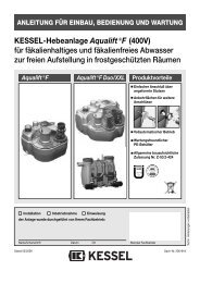
ANLEITUNG FÜR EINBAU, BEDIENUNG UND WARTUNG<br />
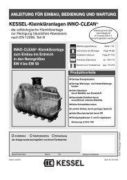
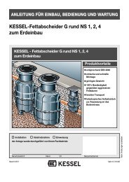
<strong>KESSEL</strong>-<strong>Kleinkläranlagen</strong> <strong>INNO</strong>-CLEAN ®<br />
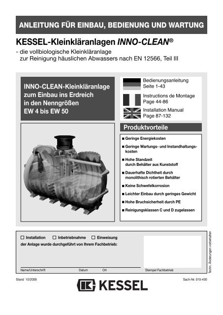
- die vollbiologische Kleinkläranlage<br />
zur Reinigung häuslichen Abwassers nach EN 12566, Teil III<br />
<strong>INNO</strong>-CLEAN-Kleinkläranlage<br />
zum Einbau ins Erdreich<br />
in den Nenngrößen<br />
EW 4 bis EW 50<br />
Bedienungsanleitung<br />
Seite 1-43<br />
Instructions de Montage<br />
Page 44-86<br />
Installation Manual<br />
Page 87-132<br />
Produktvorteile<br />
Geringe Energiekosten<br />
Geringe Wartungs- und Instandhaltungskosten<br />
Hohe Standzeit<br />
durch Behälter aus Kunststoff<br />
Dauerhafte Dichtheit durch<br />
monolithisch rotierten Behälter<br />
Keine Schwefelkorrosion<br />
Leichter Einbau durch geringes Gewicht<br />
Hohe Bruchsicherheit durch PE<br />
Reinigungsklassen C und D zugelassen<br />
Installation Inbetriebnahme Einweisung<br />
der Anlage wurde durchgeführt von Ihrem Fachbetrieb:<br />
Name/Unterschrift Datum Ort<br />
Stempel Fachbetrieb<br />
Techn. Änderungen vorbehalten<br />
Stand 10/2009<br />
Sach-Nr. 010-430
1. Sicherheitshinweise<br />
Achtung! Erstickungsgefahr beim Betreten der Anlage<br />
Das Personal für Montage, Bedienung, Wartung und Reparatur muss die entsprechende Qualifikation<br />
für diese Arbeiten aufweisen.<br />
Der Verantwortungsbereich, die Zuständigkeit und die Überwachung des Personals müssen durch<br />
den Betreiber genau geregelt sein.<br />
Die Betriebssicherheit der gelieferten Anlage ist nur bei bestimmungsgemäßer Verwendung gewährleistet.<br />
Die Grenzwerte der technischen Daten dürfen auf keinen Fall überschritten werden.<br />
Diese Anlage enthält elektrische Spannungen und steuert mechanische Anlagenteile. Bei Nichtbeachtung<br />
der Bedienungsanleitung können erhebliche Sachschäden, Körperverletzungen oder tödliche<br />
Unfälle die Folge sein.<br />
Bei Montage, Bedienung, Wartung und Reparatur der Anlage sind die Unfallverhütungsvorschriften,<br />
die in Frage kommenden DIN- und VDE-Normen und Richtlinien zu beachten.<br />
Dies sind u.a.:<br />
• „Unfallverhütungsvorschriften - Bauarbeiten“ BGV C22 bisher VBG 37<br />
• „Baugruben und Gräben, Böschungen, Arbeitsraumbreite, Verbau“ DIN 4124<br />
• „Verlegung und Prüfung von Abwasserleitungen und -kanälen“ DIN EN 1610<br />
• „Richtlinien für Arbeiten in Behältern und engen Räumen“ BGR 117 bisher ZH1/77<br />
Die Abdeckung der Kleinkläranlage muss gegen unbefugtes Öffnen (insbesondere durch Kinder)<br />
auch während der Arbeitspausen ausreichend gesichert sein.<br />
Warnung !<br />
Die Anlage besteht aus mehreren Komponenten. Beachten Sie deshalb die einzelnen Kapitel in der<br />
Bedienungsanleitung. Bei jeder Montage, Wartung, Inspektion und Reparatur an einer der Komponenten<br />
ist immer die Gesamtanlage durch ziehen des Netzsteckers an der Steuereinheit außer Betrieb<br />
zu setzen und gegen Wiedereinschalten zu sichern. Stellen Sie sicher, dass der Zufluss von Abwasser<br />
während der Montage unterbrochen ist.<br />
Das Steuergerät steht unter Spannung und darf nicht geöffnet werden.<br />
Nur Elektrofachkräfte dürfen Arbeiten an elektrischen Einrichtungen durchführen.<br />
Der Begriff Elektrofachkraft ist in der VDE 0105 definiert.<br />
Arbeiten am Verdichter, die über die im Kapitel Inspektion und Wartung beschriebenen Tätigkeiten<br />
hinausgehen, sind unzulässig.<br />
Es ist sicherzustellen, dass sich die Elektrokabel sowie alle anderen elektrischen Anlagenteile in<br />
einem einwandfreien Zustand befinden. Bei Beschädigung darf die Anlage auf keinen Fall in Betrieb<br />
genommen werden.<br />
Achtung !<br />
Umbau oder Veränderungen der Anlage sind nur in Absprache mit dem Hersteller zu tätigen. Originalersatzteile<br />
und vom Hersteller zugelassenes Zubehör dienen der Sicherheit. Die Verwendung anderer<br />
Teile kann die Haftung für die daraus entstehenden Folgen aufheben.<br />
2
Inhaltsverzeichnis<br />
1. Sicherheitshinweise .......... .............................................................................................. Seite 2<br />
2. Allgemeines 2.1 Einsatzbereich ........................................................................ Seite 5<br />
2.2 Anlagenbeschreibung .............................................................. Seite 5<br />
2.3 Anlagenkonfiguration .............................................................. Seite 6<br />
2.4 Maße und Nutzvolumen .......................................................... Seite 11<br />
2.5 Funktionsbeschreibung ........................................................... Seite 12<br />
3. Verpackung, Transport 3.1 Verpackung.............................................................................. Seite 14<br />
und Lagerung 3.2 Transport................................................................................. Seite 14<br />
3.3 Lagerung ................................................................................. Seite 14<br />
4. Einbau und Montage 4.1 Einbauort................................................................................. Seite 15<br />
4.2 Baugrube................................................................................. Seite 15<br />
4.3 Sauberkeitsschicht.................................................................. Seite 15<br />
4.4 Einsetzen ................................................................................ Seite 16<br />
4.5 Behälter befüllen..................................................................... Seite 16<br />
4.6 Verfüllung Baugrube................................................................ Seite 16<br />
4.7 Verrohrung .............................................................................. Seite 16<br />
4.8 Verlegung der Verbindungsleitungen...................................... Seite 17<br />
4.9 Montage der Aufsatzstücke..................................................... Seite 17<br />
4.10 Befüllen................................................................................... Seite 18<br />
4.11 Einbau Steuereinheit und Verdichter....................................... Seite 19<br />
5. Inbetriebnahme 5.1 Anlage in Betriebsbereitschaft setzen..................................... Seite 21<br />
5.2 Pflichten des Betreibers .......................................................... Seite 23<br />
5.3 Einweisung Kunde .................................................................. Seite 23<br />
6. Betrieb und Entsorgung 6.1 Betrieb..................................................................................... Seite 24<br />
6.2 Eigenkontrolle des Betreibers ................................................. Seite 24<br />
6.3 Was nicht in die biol. Kleinkläranlage gehört........................... Seite 25<br />
6.4 Entsorgung.............................................................................. Seite 26<br />
7. Wartung 7.1 Vorklärung und Belebung........................................................ Seite 27<br />
7.2 Verdichter ................................................................................ Seite 27<br />
8. Steuerung der Kleinkläranlage 8.1 Systemmenü........................................................................... Seite 30<br />
8.2 Informationsmenü................................................................... Seite 30<br />
8.3 Wartungsmenü........................................................................ Seite 30<br />
9. Störungen und Abhilfemaßnahmen ............................................. ................................................... Seite 33<br />
10. Gewährleistung ..... ................................................................................................. Seite 36<br />
11. Anlagenpass und Werkabnahme ....................................................................................................... Seite 47<br />
12. Konformitätserklärung ....................................................................................................... Seite 38<br />
13. Betriebstagebuch ....................................................................................................... Seite 39<br />
14. Wartungscheckliste ....................................................................................................... Seite 40<br />
15. Technische Daten ....................................................................................................... Seite 41<br />
16. Übergabeprotokoll ....................................................................................................... Seite 43<br />
3
Sehr geehrter Kunde,<br />
wir freuen uns, dass Sie sich für ein Produkt von <strong>KESSEL</strong> entschieden haben.<br />
Die gesamte Anlage wurde vor Verlassen des Werkes einer strengen Qualitätskontrolle unterzogen. Prüfen Sie bitte dennoch<br />
sofort, ob die Anlage vollständig und unbeschädigt bei Ihnen angeliefert wurde. Im Falle eines Transportschadens<br />
beachten Sie bitte die Anweisungen in Kapitel „Gewährleistung“ dieser Anleitung.<br />
Diese Einbau-, Bedienungs- und Wartungsanleitung enthält wichtige Hinweise, die bei Montage, Bedienung, Wartung und<br />
Reparatur zu beachten sind. Vor allen Arbeiten an der Anlage müssen der Betreiber sowie das zuständige Fachpersonal<br />
diese Anleitung sorgfältig lesen und befolgen.<br />
<strong>KESSEL</strong> GmbH<br />
4
2. Allgemeines<br />
2.1 Einsatzbereich<br />
<strong>INNO</strong>-CLEAN ® , die Kleinkläranlage von <strong>KESSEL</strong>, ist eine<br />
Reinigungsanlage für häusliche Abwässer nach EN 12566,<br />
Teil III. Für Niederschlagsabwässer, Abwässer aus der Tierhaltung<br />
sowie Schwimmbadabwässer ist diese Anlage nicht<br />
vorgesehen. In einem biologischen Verfahren, reinigt diese<br />
Kleinkläranlage häusliches Abwasser und passt sich automatisch<br />
den anfallenden Mengen an. Das Abwasser wird je<br />
nach Anlagengröße in einem oder mehreren Kunststoffbehältern<br />
gesammelt und gereinigt. Dieser Behälter ist zum<br />
Verbau im Erdreich vorgesehen. Die Belüftung und Umwälzung<br />
wird von einem Verdichter bereitgestellt und durch<br />
eine Steuereinheit vollautomatisch geregelt. Der Verdichter<br />
und die Steuerung sind zum freien Einbau in frostgeschützten,<br />
überflutungssicheren und trockenen Räumen vorgesehen.<br />
Die Zuleitung muß rückstaufrei an die <strong>INNO</strong>-CLEAN ®<br />
angeschlossen werden. Zusätzlich zu der Kleinkläranlage<br />
muss für eine angemessene Abwasserableitung nach ATV-<br />
DVWK-A138 gesorgt werden. Weiterhin ist in jedem Fall die<br />
Kommune, der Landkreis oder die untere Wasserbehörde<br />
für eine Genehmigung zur Errichtung und den Betrieb der<br />
Anlage zuständig.<br />
2.2 Anlagenbeschreibung<br />
<br />
<br />
<br />
<br />
<br />
<br />
<br />
<br />
<br />
<br />
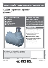
<strong>KESSEL</strong>-<strong>INNO</strong>-CLEAN ® besteht aus zwei Hauptsegmenten.<br />
Innerhalb eines frostfreien, überflutungssicheren und<br />
trockenen Raumes befindet sich die Steuereinheit; der<br />
Kunststoffbehälter, in dem der Klärungsprozess stattfindet,<br />
wird außerhalb des Gebäudes im Erdreich verbaut.<br />
Steuereinheit (Steuerung und Verdichter)<br />
Zulauf<br />
Vorklärkammer<br />
Belebungskammer<br />
Belüfterkerze<br />
Sickerschacht (optional)<br />
Ventilblock<br />
Klärturm mit integriertem Probenahmebehälter,<br />
Luftheber und Ablauf<br />
Kabelleerrohr<br />
Lüftungsleitung<br />
5
2. Allgemeines<br />
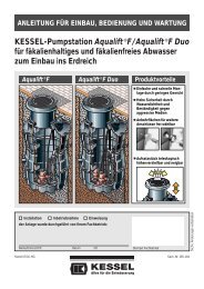
2.3 Anlagenkonfiguration<br />
Seitenansicht<br />
Behälter EW 4 - 6<br />
Nutzvolumen 4800 l<br />
Seitenansicht<br />
Behälter EW 8 -10<br />
Nutzvolumen 7600 l<br />
Frontansicht<br />
6
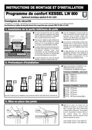
Anlagenkonfiguration EW 4, EW 6, EW 8 und EW 10<br />
2. Allgemeines<br />
7
2. Allgemeines<br />
Anlagenkonfiguration EW 12, EW 14, EW 16 und EW 20<br />
8
2. Allgemeines<br />
Anlagenkonfiguration EW 22 bis EW 30<br />
9
2. Allgemeines<br />
Anlagenkonfiguration EW 30 bis EW 50<br />
10
2. Allgemeines<br />
2.4 Maße und Nutzvolumen<br />
Kleinkläranlage Innoclean Klasse "C", mit Abdeckung Kl. A/B, tagwasserdicht und unverriegelt<br />
Einwohnergleichwert<br />
(EW)<br />
Artikelnummer Reinigungsklasse<br />
Behälter<br />
Zu-/Ablauf<br />
(DN)<br />
Gesamtvolumen<br />
(l)<br />
L<br />
(mm)<br />
B<br />
(mm)<br />
T<br />
(mm)<br />
T EÜ<br />
(mm)<br />
GW<br />
(mm)<br />
h2<br />
(mm)<br />
h1<br />
(mm)<br />
h leer<br />
(mm)<br />
Gewicht<br />
(ca. kg)<br />
C D Gesamt Behälter 1 Behälter 2 Behälter 3 Behälter 4 Behälter 5 Behälter 6 l1 l2 l3 b1=b2 min max<br />
4 97804 RC 97804 RD 1 150 4800 4800 2350 2000 800 1005 T-255 1775 1875 1775 2000 530<br />
6 97806 RC 97806 RD 1 150 4800 4800 2350 2000 800 1005 T-255 1775 1875 1775 2000 530<br />
8 97808 RC 97808 RD 1 150 7600 7600 3470 2000 800 1005 T-255 1775 1875 1775 2000 700<br />
10 97810 RC 97810 RD 1 150 7600 7600 3470 2000 800 1005 T-255 1775 1875 1775 2000 700<br />
12 97812 RC 97812 RD 2 150 9600 4800 4800 2350 2350 2000 800 1005 T-255 1775 1875 1775 2000 970<br />
14 97814 RC 97814 RD 2 150 12400 7600 4800 3470 2350 2000 800 1005 T-255 1775 1875 1775 2000 1130<br />
16 97816 RC 97816 RD 2 150 12400 7600 4800 3470 2350 2000 800 1005 T-255 1775 1875 1775 2000 1130<br />
18 97818 RC 97818 RD 2 150 15200 7600 7600 3470 3470 2000 800 1005 T-255 1775 1875 1775 2000 1300<br />
20 97820 RC 97820 RD 2 150 15200 7600 7600 3470 3470 2000 800 1005 T-255 1775 1875 1775 2000 1300<br />
22 97822 RC 97822 RD 3 150 18300 5350 7600 5350 2350 3470 2350 2000 800 1005 T-255 1775 1875 1775 2000 1430<br />
24 97824 RC 97824 RD 3 150 21000 8100 4800 8100 3470 2350 3470 2000 800 1005 T-255 1775 1875 1775 2000 1540<br />
26 97826 RC 97826 RD 3 150 21000 8100 4800 8100 3470 2350 3470 2000 800 1005 T-255 1775 1875 1775 2000 1540<br />
28 97828 RC 97828 RD 3 150 23800 8100 7600 8100 3470 3470 3470 2000 800 1005 T-255 1775 1875 1775 2000 1700<br />
30 97830 RC 97830 RD 3 150 23800 8100 7600 8100 3470 3470 3470 2000 800 1005 T-255 1775 1875 1775 2000 1700<br />
32 97832 RC 97832 RD 6 150 31000 5350 5350 4800 5350 4800 5350 2350 2350 2350 2000 800 1005 T-255 1775 1875 1775 2000 2620<br />
34 97834 RC 97834 RD 6 150 31000 5350 5350 4800 5350 4800 5350 2350 2350 2350 2000 800 1005 T-255 1775 1875 1775 2000 2620<br />
36 97836 RC 97836 RD 6 150 31000 5350 5350 4800 5350 4800 5350 2350 2350 2350 2000 800 1005 T-255 1775 1875 1775 2000 2620<br />
38 97838 RC 97838 RD 6 150 36600 5350 5350 7600 5350 7600 5350 2350 3470 2350 2000 800 1005 T-255 1775 1875 1775 2000 2950<br />
40 97840 RC 97840 RD 6 150 36600 5350 5350 7600 5350 7600 5350 2350 3470 2350 2000 800 1005 T-255 1775 1875 1775 2000 2950<br />
42 97842 RC 97842 RD 6 150 36600 5350 5350 7600 5350 7600 5350 2350 3470 2350 2000 800 1005 T-255 1775 1875 1775 2000 2950<br />
44 97844 RC 97844 RD 6 150 36600 5350 5350 7600 5350 7600 5350 2350 3470 2350 2000 800 1005 T-255 1775 1875 1775 2000 2950<br />
46 97846 RC 97846 RD 6 150 42000 8100 8100 4800 8100 4800 8100 3470 2350 3470 2000 800 1005 T-255 1775 1875 1775 2000 3150<br />
48 97848 RC 97848 RD 6 150 42000 8100 8100 4800 8100 4800 8100 3470 2350 3470 2000 800 1005 T-255 1775 1875 1775 2000 3150<br />
50 97850 RC 97850 RD 6 150 42000 8100 8100 4800 8100 4800 8100 3470 2350 3470 2000 800 1005 T-255 1775 1875 1775 2000 3150<br />
11
2. Allgemeines<br />
2.5 Funktionsbeschreibung<br />
Der Klärprozess wird vollautomatisch von<br />
der Steuereinheit geregelt. Ein Klärzyklus<br />
dauert ca. 8 Stunden und wird durch<br />
Abführen des geklärten Wassers beendet.<br />
Der Klärungsprozess basiert auf Mikroorganismen,<br />
die während der Behandlungsphase<br />
das Abwasser reinigen.<br />
1. Einleitung des Schwarzwassers<br />
(gesamtes häusliches Abwasser)<br />
Sämtliches häusliches Abwasser gelangt<br />
in die Vorklärkammer. Dort sinken die<br />
Schwerteile zum Boden ab und bilden eine<br />
Schlammschicht. Der Abwasserschlamm<br />
verbleibt in der Vorklärkammer, verdichtet<br />
sich und muss bei Erreichen der maximalen<br />
Aufnahmekapazität entsorgt werden.<br />
2. Füllen der Belebungskammer<br />
(Beschickung)<br />
Die Belebungskammer wird mit dem Abwasser<br />
aus der Vorklärkammer befüllt.<br />
Über den Beschickungsheber wird ein definiertes<br />
Abwasservolumen aus der Vorklärkammer<br />
in die Belebungskammer geführt.<br />
3. Behandlungsphase des Abwassers<br />
(Normal-, Spar- und Urlaubsphase)<br />
In der Belebungskammer wird das Abwasser<br />
mit kurzen Belüfterstößen (Membranrohrbelüfter)<br />
verwirbelt. Durch eine phasenweise<br />
Belüftung gelangt Sauerstoff in<br />
das Abwasser und Mikroorganismen erhalten<br />
Sauerstoff für den Nährstoffabbau.<br />
Dabei bildet sich Belebtschlamm. Der<br />
Stoffwechsel der Mikroorganismen reinigt<br />
das Abwasser.<br />
Die Behandlungsphase dauert in der Regel<br />
ca. sechs Stunden. Darüber hinaus reguliert<br />
sich die Anlage gemäß ihrer Beschickung.<br />
Die Abwasserbehandlung läuft<br />
dann im Rahmen der “Normalphase”, der<br />
“Sparphase” oder der “Urlaubsphase” ab.<br />
(siehe Punkt 6.1)<br />
12
2. Allgemeines<br />
4. Absetzphase<br />
Nach der Behandlungsphase folgt eine<br />
zweistündige Absetzphase. Alle in dem Abwasser<br />
enthaltenen Feststoffe, sowie der<br />
Belebtschlamm setzen sich am Beckenboden<br />
ab somit bildet sich im oberen Bereich<br />
eine Klarwasserschicht und am Boden eine<br />
Schlammschicht aus Mikroorganismen.<br />
5. Abziehen des Klarwassers<br />
(Klarwasserabzug)<br />
Oberhalb dieser Schlammschicht verbleibt<br />
nun gesäubertes Wasser das über den<br />
Luftheber für den Klarwasserabzug in die<br />
Vorflut oder Versickerung geführt wird.<br />
6. Rückpumpen des Belebtschlamms<br />
(Schlammabzug)<br />
Überschüssiger Belebtschlamm wird in die<br />
Vorklärung zurückgehoben.<br />
13
3. Verpackung, Transport und Lagerung<br />
Das Kapitel Sicherheitshinweise ist zu beachten!<br />
3.1 Verpackung<br />
Eine Verpackung der Behälter zum Zwecke des Transports<br />
bzw. der Lagerung ist bei Beachtung der nachfolgenden<br />
Punkte nicht notwendig.<br />
Hinweis: Der Eintrag von Fremdkörpern (Schmutz, Staub<br />
etc.) während der Verbauphase in die Kläranlage ist zu vermeiden.<br />
Ggf. sind an allen Öffnungen Abdeckungen anzubringen.<br />
3.2 Transport<br />
• Der Transport ist nur von solchen Firmen durchzuführen,<br />
die über fachliche Erfahrungen, geeignete Geräte, Einrichtungen<br />
und Transportmittel, sowie ausreichend geschultes<br />
Personal verfügen.<br />
• Die Behälter müssen so transportiert werden, daß sie nicht<br />
unzulässig belastet werden und dass eine Lageveränderung<br />
während des Transports ausgeschlossen ist. Im Falle<br />
einer Verspannung ist diese so vorzunehmen, dass eine<br />
Beschädigung der Behälter ausgeschlossen ist (z.B. Verwendung<br />
von Gewebe- oder Schlaufengurten). Die Verwendung<br />
von Drahtseilen oder Ketten ist nicht zulässig.<br />
• Die Behälter sind gegen unzulässige Lageveränderungen<br />
während der Beförderung zu sichern. Durch die Art der Befestigung<br />
dürfen die Behälter nicht beschädigt werden.<br />
3.3 Lagerung<br />
Sollte eine Lagerung der Behälter vor dem Einbau erforderlich<br />
sein, so darf diese nur kurzzeitig und auf ebenem, von<br />
scharfkantigen Gegenständen befreitem Untergrund geschehen.<br />
Bei Lagerung im Freien sind die Behälter gegen<br />
Beschädigung, Sturmeinwirkung und Verschmutzung zu<br />
schützen.<br />
• Beim Abheben, Verfahren und Absetzen der Behälter müssen<br />
stoßartige Beanspruchungen vermieden werden.<br />
Kommt ein Gabelstapler zum Einsatz, müssen während<br />
der Fahrt mit dem Gabelstapler die Behälter gesichert werden.<br />
Ein Rollen oder Schleifen der Behälter über den Untergrund<br />
ist nicht zulässig.<br />
14
4. Einbau und Montage<br />
Während der Zwischenlagerung der Kleinkläranlage<br />
sowie bis zum Abschluss der Einbauarbeiten, müssen<br />
an der Baustelle geeignete Sicherungsmaßnahmen getroffen<br />
werden, um Unfälle und Beschädigungen der<br />
Kleinkläranlage zu verhindern.<br />
Das Kapitel Sicherheitshinweise ist zu beachten.<br />
Einbauvoraussetzungen<br />
Der Einbau ist nur von solchen Firmen durchzuführen, die<br />
über fachliche Erfahrungen, geeignete Geräte und Einrichtungen<br />
sowie ausreichend geschultes Personal verfügen.<br />
Eine Erfassung der Bodenbeschaffenheit im Hinblick auf die<br />
bautechnische Eignung muss vorgenommen worden sein<br />
(Bodenklassifikation für bautechnische Zwecke DIN 18196).<br />
Der maximal auftretende Grundwasserstand muss ebenso<br />
vor Beginn der Bauarbeiten festgestellt werden. Eine ausreichende<br />
Ableitung (Drainage) von Sickerwässern ist bei<br />
wasserundurchlässigen Böden zwingend notwendig. Die<br />
auftretenden Belastungsarten wie max. Verkehrslasten und<br />
Einbautiefe müssen abgeklärt sein.<br />
Kurzübersicht Einbauschritte (siehe auch 4.1 bis 4.12)<br />
1. Einbauort festlegen.<br />
2. Baugrube ausheben.<br />
3. Sauberkeitsschicht (Behälterbett) erstellen.<br />
4. Behälter in die Baugrube einsetzen.<br />
5. Behälter in allen Kammern bis zur Hälfte mit Wasser befüllen,<br />
um Standsicherheit zu gewährleisten.<br />
6. Baugrube mit Kies (bis unter den Auslauf) lagenweise<br />
verfüllen und verdichten.<br />
7. Verrohrung der Zu- und Abläufe, sowie der Lüftungsleitung<br />
und Kabelleerrohrleitung.<br />
8. Belüftungsschlauch und Steuerleitung im Kabelleerrohr<br />
verlegen.<br />
9. Aufsatzstück aufsetzen und mit Klemmring fixieren.<br />
10. Abschließende Befüllung des Behälters.<br />
11. Wandkonsole, Verdichter und Steuerung montieren und<br />
anschließen.<br />
12. Inbetriebnahme der Anlage (siehe Kapitel 5).<br />
4.1 Einbauort<br />
Unmittelbar vor dem Einbringen des Behälters in die Baugrube<br />
hat der Sachkundige der mit dem Einbau beauftragten<br />
Firma folgendes zu prüfen und zu bescheinigen:<br />
- Die Unversehrtheit der Behälterwand;<br />
- den ordnungsgemäßen Zustand der Baugrube, insbesondere<br />
hinsichtlich der Abmessungen und Sohlenbettung;<br />
- Beschaffenheit der Körnung des Verfüllmaterials.<br />
Die Distanz zwischen Steuereinheit und Behälter darf maximal<br />
12,5 m (Option: 30 m - Schlauchpaket = Distanz 27,5<br />
m) betragen. Sollte dies nicht ausreichen, so kann die<br />
Steuereinheit und der Verdichter in einem optionalen Schaltschrank<br />
installiert werden.<br />
Der max. Abstand bei Anlagen mit mehreren Behältern beträgt<br />
3,0 m. Sollten Sie diesen Abstand überschreiten, so<br />
sind zusätzliche Schläuche notwendig.<br />
4.2 Baugrube<br />
➁<br />
➀<br />
➁<br />
➀<br />
Die größeren <strong>INNO</strong>-CLEAN ® -Anlagen bestehen aus zwei oder mehr Behältern.<br />
Diese lassen sich individuell in verschiedenen Varianten anordnen. So können<br />
schwierigste Einbausituationen leicht gemacht werden.<br />
Hinweis: Bei Mehrbehälteranlagen eine Baugrube für alle<br />
Behälter ausheben!<br />
Der Baugrund muss waagerecht und eben sein, um die Anlage<br />
vollflächig aufstellen zu können. Außerdem muss der<br />
Baugrund eine ausreichende Tragfähigkeit gewährleisten.<br />
Als Unterbau ist ein verdichteter Rundkornkies (Körnung<br />
8/16, Dicke mind. 30 cm, Dpr=95%) und darauf 3 - 10 cm<br />
verdichteter Sand notwendig. Der Abstand zwischen Baugrubenwand<br />
und Behälter muss mindestens 70 cm betragen.<br />
Die Böschungen müssen der DIN 4124 entsprechen.<br />
• Einbau im Gelände mit Hanglage<br />
Beim Einbau der Kleinkläranlage in ein Gelände mit Hanglage<br />
ist unbedingt darauf zu achten, dass der seitlich schiebende<br />
Erddruck bei nicht gewachsenem Boden durch eine<br />
entsprechend ausgelegte Stützmauer abgefangen wird.<br />
• Frostfreie Tiefe<br />
Beachten Sie beim Einbau der Kleinkläranlage unbedingt<br />
die örtlich festgelegte frostfreie Tiefe. Um auch im Winter<br />
einen reibungslosen Betrieb zu gewährleisten, ist beim<br />
Einbau ebenso die Zu- und Ablaufleitung in frostfreier<br />
Einbautiefe zu verlegen. In aller Regel liegt die frostfreie<br />
Tiefe, wenn nicht anders durch die Behörde angegeben, bei<br />
ca. 80 cm.<br />
4.3 Sauberkeitsschicht<br />
Unterbau: Rundkornkies<br />
(Körnung 8/16) nach DIN 4226-1<br />
Behälterbett: Sand<br />
Behälterumhüllung: Rundkornkies<br />
(Körnung 8/16) nach DIN 4226-1<br />
Bereich außerhalb<br />
Behälterumhüllung: Material geeigneter Beschaffenheit<br />
Deckschicht: Humus o.ä. (Belastungsklasse beachten)<br />
15
4. Einbau und Montage<br />
<br />
<br />
<br />
≤ 20cm<br />
≤ 30cm<br />
≤ 30cm<br />
≤ 30cm<br />
≥ 50cm<br />
<br />
≥ 50cm<br />
≤ 30cm<br />
≤ 30cm<br />
≤ 30cm<br />
≤ 30cm<br />
≤ 30cm<br />
β nach<br />
DIN 4124<br />
<br />
<br />
≤ 30cm<br />
3-10cm<br />
≥ 30cm<br />
≥ 70cm<br />
Unterbau: Rundkornkies (max. Körnung 8/16) nach<br />
DIN 4226-1 verdichtet mit Dpr=95%<br />
Behälterbett: verdichteter Sand<br />
Behälter<br />
Behälterumhüllung: Rundkornkies (max. Körnung<br />
≥ 70cm<br />
8/16) nach DIN 4226-1 verdichtet mit Dpr=95%<br />
Bereich außerhalb Behälterumhüllung:<br />
Material geeigneter Beschaffenheit<br />
Deckschicht: Humus, Straßenbelag, Beton o.ä.<br />
4.4 Einsetzen<br />
Der Behälter ist mit Hilfe einer geeigneten Vorrichtung<br />
stoßfrei in die Baugrube einzubringen und auf die Sohlenbettung<br />
aufzusetzen (siehe auch Kapitel „Transport“).<br />
Fließrichtung und Fließrichtungspfeile auf dem Behälter beachten!<br />
4.5 Behälter befüllen<br />
Behälter in beiden Kammern mit Klarwasser befüllen (ca. 80<br />
cm) um eine bessere Standfestigkeit zu erlangen.<br />
4.6 Verfüllung Baugrube<br />
Generell sollte das Befüllen des Behälters und die Verfüllung<br />
der Baugrube parallel ausgeführt werden. Die Verfüllung der<br />
Baugrube erfolgt bis Unterkante Zu- und Ablauf, sowie der<br />
Lüftungs- und Kabelleerrohrleitung. Die Behälterumhüllung<br />
muss in einer Breite von mindestens 50 cm hergestellt werden.<br />
Die einzelnen Lagen des Verfüllmaterials sollten nicht<br />
höher als 30 cm sein. Sie sind mit leichten Verdichtungsgeräten<br />
zu verdichten (mind. Dpr=95%). Eine Beschädigung<br />
der Behälterwand und eine Verlagerung der Behälter während<br />
und nach dem Einbau muss ausgeschlossen werden.<br />
4.7 Verrohrung<br />
Die Zu-/Ablaufleitungen, sowie Verbindungsleitungen sind<br />
frostfrei (siehe 4.2) zu verlegen und anzuschließen, sobald<br />
die Baugrube bis zur Unterkante der Zu- und Ablaufleitung<br />
verfüllt und verdichtet ist.<br />
Der Übergang von Fallleitungen in horizontale Leitungen ist<br />
mit zwei 45°-Bogenformstücken und einem mindestens 250<br />
mm langen Zwischenstück auszuführen. Vor dem Inno-<br />
Clean-Behälter ist eine Beruhigungsstrecke vorzusehen,<br />
deren Länge mindestens dem 10-fachen der Nennweite der<br />
Rohrleitung entspricht.<br />
• Kabelleerrohr<br />
Für die Leitungsverbindung zwischen Steuergerät/Kompressor<br />
und Ventilblock/Inno-Clean-Behälter muss ein Kabelleerrohr<br />
(KG-Rohr aus PVC-U in der Dimension DN 100)<br />
verlegt werden. Das Leerrohr sollte über seine gesamte<br />
Länge über ein stetiges Gefälle von ≥ 2° zum Behälter verfügen.<br />
Für die Durchführung durch die Gebäudewand empfiehlt<br />
<strong>KESSEL</strong> auf handelsübliche Wanddurchführungen<br />
zurück zu greifen (siehe Bild). Zur Abdichtung des Kabelleerrohres<br />
im Gebäude, sollte die Abdeckung von <strong>KESSEL</strong><br />
16
4. Einbau und Montage<br />
4.8 Verlegung der Verbindungsleitungen zur Steuereinheit<br />
(Belüftungsschlauch und Steuerleitung)<br />
Die Steuerleitung, sowie der Belüftungsschlauch sind zwischen<br />
Ventilblock und Steuereinheit im Kabelleerrohr zu verlegen<br />
( siehe Vorgehen).<br />
Luftschlauch zum Verdichter<br />
Betondecke<br />
Kellerwand<br />
Kabelleerrohrabdichtung<br />
Art. Nr. 97 711<br />
KG-Rohr DN 100<br />
Dichtung<br />
Art.-Nr. 860 116<br />
Dichtung für<br />
Rohrdurchführung<br />
Schnellverbinder<br />
Ventilblock<br />
Verriegelungsbügel<br />
Ventilblock<br />
Inno-Clean<br />
handelsübliche<br />
Wanddurchführung<br />
z. B.<br />
Fa. Steelter oder<br />
Fa. DOYMA<br />
DN 100<br />
Gefälle mind. 2°<br />
fallend zum Behälter<br />
Behälterwand<br />
Inno-Clean<br />
Adapterplatte<br />
(Kabelleerrohrabdichtung Art.-Nr. 97711) zum Schutz vor<br />
Geruchsbelästigungen eingesetzt werden.<br />
Richtungsänderungen sollten über Bogenformstücke mit<br />
maximal 30° Abwinkelung realisiert werden.<br />
Achtung: Alle Leitungen sollten temporär bis zum endgültigen<br />
Anschluß, mit Klebeband verschlossen werden, um<br />
Schmutzeintrag während des Durchschiebens zu vermeiden.<br />
Bemerkung:<br />
Die Behälter können im Bereich der Dome angebohrt werden,<br />
um zusätzliche Anschluß- und Lüftungsleitungen herzustellen.<br />
Hierzu sind Original-Bohrkronen und Rohrdurchführungsdichtungen<br />
von <strong>KESSEL</strong> zu verwenden (<strong>KESSEL</strong>-<br />
Bohrkronen DN 50 - DN 150, Art.-Nr. 50100,<br />
<strong>KESSEL</strong>-Rohrdurchführungsabdichtungen:<br />
DN 50 Art.-Nr. 850114<br />
DN 70 Art.-Nr. 850116<br />
DN 100 Art.-Nr. 850117<br />
DN 125 Art.-Nr. 850118<br />
DN 150 Art.-Nr. 850119)<br />
Die Bohrungen sollten auf möglichst planen Flächen erfolgen.<br />
Für eine optimale Abdichtung der Bohrung sollte der<br />
Abstand zwischen dem Rand der Bohrung und unebener<br />
Kontur mindestens 15 mm betragen, damit die Dichtung umlaufend<br />
gleichmäßig um die Bohrung anliegt.<br />
Lasche zum<br />
Einhängen der<br />
Steuerleitung<br />
Steuerleitung<br />
Luftschläuche zu den Drucklufthebern<br />
Vorgehen:<br />
- Öffnen des Verriegelungsbügels am Ventilblock im Behälter<br />
- Entnahme des Ventilblocks von der Adapterplatte<br />
- grauen Belüftungsschlauch und Steuerleitung durch das<br />
Kabelleerrohr ziehen<br />
- Belüftungsschlauch mittels Schnellverbinder am Ventilblock<br />
anschließen (siehe 4.11 Punkt 5)<br />
- Ventilblock auf Adapterplatte einsetzen<br />
- Achtung: Steuerleitung muss in vorgesehene Lasche eingeklipst<br />
werden (siehe Abb.) um ein korrektes Verriegeln<br />
mit der Adapterplatte zu gewährleisten.<br />
- Ventilblock auf korrekten Sitz prüfen und Verriegelungsbügel<br />
schließen<br />
4.9 Montage der Aufsatzstücke<br />
Zuerst die Dichtung (siehe Zeichnung 4.9) in die vorgesehene<br />
Sicke im Dom einlegen.<br />
• Entlüftung<br />
Die Be- und Entlüftung der Anlage erfolgt über eine Lüftungsleitung<br />
der Größe DN 100 und wird an der entsprechenden Öffnung<br />
am Dom angeschlossen. Eine zusätzliche Lüftungsleitung<br />
kann am Dom angeschlossen werden (siehe Abb. S. 5).<br />
Hierzu ist die entsprechende Bohrkrone und Rohrdurchführungsdichtung<br />
von <strong>KESSEL</strong> zu verwenden . <strong>KESSEL</strong> empfiehlt<br />
die Verwendung eines Aktivkohlefilters zur Vermeidung<br />
von Geruchsbelästigung.<br />
17
4. Einbau und Montage<br />
Die Dichtlippe soll auf der Innenseite des<br />
Ringes nach unten zeigen.<br />
Das teleskopische <strong>KESSEL</strong>-Aufsatzstück im unteren Bereich<br />
mit Gleitmittel einfetten und in die Behälteröffnung einstecken,<br />
in die gewünschte Position bringen und mittels<br />
Klemmring fixieren. Alternativ kann Gleitmittel auch auf den<br />
Dichtring aufgetragen werden. Mit Hilfe des vorhandenen<br />
Klemmringes kann nun das Aufsatzstück in der gewünschten<br />
Position (Ausrichtung an der Geländeoberkante) fixiert<br />
werden. Die Feinjustierung auf die endgültige Höhe erfolgt<br />
dann mittels der Stellschrauben. Bodenneigungen können<br />
durch das stufenlos höhenverstellbare und bis 5° neigbare<br />
Aufsatzstück ausgeglichen werden. Die mitgelieferten Aufkleber<br />
der “Innofanten” sind auf die gereinigte und trockene<br />
Innenfläche am Aufsatzstück anzubringen (siehe Bild).<br />
Wichtig: Der grüne “Innofant” ist auf die Zulaufseite zu kleben<br />
und der rote auf die Auslaufseite!<br />
Anschließend das Aufsatzstück ausreichend verfüllen und<br />
verdichten.<br />
Zulauf<br />
➔<br />
➔<br />
Auslauf<br />
4.10 Abschließende Befüllung des Behälters<br />
Vor dem Verfüllen nochmaliges Kontrollieren der Zu- und Ablaufleitung, sowie der Entlüftungsleitung und des Kabelleerrohrs.<br />
Das Aufsatzstück mit der Geländeoberkante abgleichen.<br />
18
4. Einbau und Montage<br />
<br />
<br />
Netzanschluss<br />
<br />
<br />
Verdichter<br />
Wandkonsole<br />
<br />
<br />
<br />
Steuergerät<br />
Netzanschluss Verdichter<br />
<br />
<br />
<br />
Anschlussbuchse für potentialfreien Kontakt<br />
Anschluss Ventilblock<br />
(inkl. Schwimmerschalter)<br />
Anschluss externer Signalgeber<br />
<br />
Druckluftanschluss Ventilblock<br />
Anschluss Druckluftsensor<br />
<br />
Winkelstück für<br />
Anschluss Druckluftschlauch<br />
Schnellverbinder<br />
4. 11 Einbau der Steuereinheit und des Verdichters<br />
Beachten Sie bitte, daß für die Anschlussleitungen vom<br />
Behälter zur Steuereinheit ein Kabelleerrohr (DN 100) verlegt<br />
werden muss (siehe 4.7).<br />
Allgemeine Hinweise<br />
ACHTUNG: <strong>KESSEL</strong> empfiehlt, für die Ausführung von<br />
elektrischen Anschlüssen, einen Fachbetrieb des Elektrohandwerks<br />
zu beauftragen. Nehmen sie die Anlage<br />
erst nach vollständigem Einbau in Betrieb. Während der<br />
Anschlussarbeiten darf die Anlage nicht ans Netz angeschlossen<br />
sein.<br />
Steuerung und Verdichter sind in einem frostgeschützten,<br />
überflutungssicheren und trockenen Raum zu montieren.<br />
Rückstausichere Montage beachten!<br />
Auf eine gute Belüftung des Raumes in dem der Verdichter<br />
aufgestellt wird ist zu achten. Eine ausreichende Luftzirkulation,<br />
insbesondere auch bei Geräten die innerhalb eines<br />
Außenschaltschrankes untergebracht werden sollen, ist zu<br />
achten, um den Verdichter vor Überhitzung zu schützen.<br />
Eine kühle Umgebungstemperatur sichert eine hohe Lebensdauer<br />
der Membranen und Ventile.<br />
Der Verdichter sollte nicht in staubiger Umgebung betrieben<br />
werden. Ein Überhitzen durch verstopfte Filter verkürzt die<br />
Lebensdauer der Membranen und Filter.<br />
Der Verdichter soll vor direkter Sonneneinstrahlung, Regen,<br />
Schnee und Frost geschützt sein. Die angesaugte Umgebungsluft<br />
muss frei von entflammbaren oder aggressiven<br />
Gasen oder Dämpfen sein.<br />
Die Schlauchleitung ist so kurz und so gerade wie möglich<br />
zwischen Steuerung und Behälter zu verlegen. Richtungsänderungen<br />
sind über lange Bögen anstatt engen Abwinkelungen<br />
zu realisieren.<br />
Der Verdichter ist oberhalb der Steuerung auf einem geeigneten<br />
Sockel oder einer Konsole zu platzieren, um evtl.<br />
Schäden zu vermeiden.<br />
Bei der Montage auf einer instabilen Unterlage können durch<br />
Vibrationen störende Geräusche auftreten.<br />
Der Verdichter ist horizontal zu montieren, um eine einseitige<br />
Belastung der Membranen und dadurch verkürzte Lebensdauer<br />
der Komponenten zu verhindern.<br />
Der Verdichter soll auf allen 4 Gummifüßen komplett aufstehen<br />
und soll nicht wackeln.<br />
19
4. Einbau und Montage<br />
Montage und Anschluß<br />
Die Wandkonsole ist mittels beider mitgelieferter<br />
Dübel und Schrauben waagerecht an der Wand zu<br />
fixieren.<br />
<br />
<br />
<br />
<br />
<br />
<br />
<br />
<br />
Das Steuergerät durch Lösen der vier stirnseitigen<br />
Kreuzschlitzschrauben öffnen und dessen Rückwand<br />
mit den mitgelieferten vier Kreuzschlitzschrauben an<br />
den vorgebohrten Stellen der Wandkonsole (unterhalb<br />
der Abstellfläche für den Verdichter) befestigen.<br />
Anschließend ist das Steuergerät wieder zu verschließen.<br />
Achtung: Darauf achten, dass das Gerät<br />
spannungsfrei ist (siehe Sicherheitshinweise S.2)<br />
Den Verdichter auf der Abstellfläche der Wandkonsole<br />
in die dafür vorgesehenen Vertiefungen stellen.<br />
Bitte beachten Sie, dass die Kontrolllampe nach<br />
vorne gerichtet und der elektrische Anschluss des<br />
Gerätes auf der rechten Seite des Gerätes ist. Der<br />
Netzstecker des Verdichters ist mit der Schuko-<br />
Kupplung am Schaltgerät zu verbinden.<br />
Bevor das Winkelstück für den Anschluss der Druckluftleitung<br />
an den Verdichter am Gerät angeschlossen<br />
wird, ist die mitgelieferte Metallhülse in den langen<br />
Schenkel des Winkelstückes einzuschieben. Anschließend<br />
erfolgt die Montage des Winkelstückes<br />
am Stutzen des Verdichters und dessen Fixierung<br />
mittels der Federklemme am Gerät.<br />
Abweichung bei den Verdichtergrößen EL 150/200/<br />
250: Entfernen Sie den Stutzen beim Verdichter und<br />
Schrauben Sie das mitgelieferte Winkelstück am Gewinde<br />
des Verdichters ein (Gewinde mit Teflonband<br />
o.ä. abdichten). Das Einbringen der Metallhülse entfällt<br />
bei diesen Verdichtergrößen.<br />
Den Schnellverbinder durch Drehen der Verschlusskappe um 60° nach links öffnen und das lange Ende des<br />
Winkelstückes bis zum Anschlag einschieben. Die Verschlusskappe durch Rechtsdrehung schließen.<br />
Der transparente Schlauch des Druckluftsensors ist mit dem Steuergerät an der dritten Buchse von links<br />
anzuschließen. Hierfür die schwarze Überwurfmutter lösen und den innenliegenden Klemmring entnehmen,<br />
danach die Überwurfmutter und den Klemmring auf den transparenten Schlauch aufschieben, anschl.<br />
Schlauch aufstecken. Zum Schluss schwarze Überwurfmutter handfest anschrauben.<br />
Für den Anschluss der Druckluftleitung aus dem Behälter ist der graue Belüftungsschlauch im Kabelleerrohr<br />
auf passende Länge zu kürzen und ohne Abwinkelungen mit dem Schnellverbinder am Verdichter zu<br />
fixieren. Achtung: Belüftungsschlauch locker, nicht auf Spannung verlegen.<br />
Das Anschlusskabel vom Ventilblock ist in die entsprechende Buchse am Steuergerät einzustecken und mit<br />
der Verschraubung zu fixieren.<br />
20
4. Einbau und Montage<br />
Optionale Anschlüsse am Schaltgerät:<br />
Achtung: Alle optionalen Anschlüsse sind nur durch Elektrofachkräfte durchzuführen.<br />
21
5. Inbetriebnahme<br />
<br />
<br />
Display/Anzeigenfeld<br />
Bewegungstasten/Richtungstasten<br />
für die Führung durch das Programm-Menü<br />
<br />
<br />
<br />
<br />
Bestätigungstaste/OK-Taste<br />
Zurücktaste/ESC-Taste<br />
Kontrolllampe für Betriebsbereitschaft<br />
Kontrolllampe für Störungsmeldung<br />
Netzabschlusskabel<br />
Netzanschluss für Verdichter<br />
Anschluss Druckluftsensor<br />
Anschlussmöglichkeiten<br />
für externen Signalgeber<br />
<br />
Anschlus für Ventilblock<br />
<br />
<br />
Anschlussbuchse für potentialfreien Kontakt<br />
Einweisung / Übergabe<br />
Das Kapitel Sicherheitshinweise ist zu beachten! (S.2)<br />
Hinweis: Die Netzleitung muss mit einem FI-Schutzautomaten<br />
ausgerüstet sein.<br />
Die Inbetriebnahme wird von einem Fachbetrieb oder einem<br />
<strong>KESSEL</strong>-Beauftragten durchgeführt (gegen Aufpreis).<br />
Folgende Personen sollten bei der Übergabe anwesend sein:<br />
- Abnahmeberechtigter des Bauherrn<br />
- Fachbetrieb<br />
Ferner empfehlen wir die Teilnahme des Bedienungspersonals/<br />
Betreibers, Entsorgungsunternehmens<br />
0.<br />
Systemstart<br />
Systemdiagnose<br />
0.1 Sprache<br />
deutsch<br />
französisch<br />
englisch<br />
Übersicht Einweisung:<br />
5. 1. Anlage in Betriebsbereitschaft setzen<br />
5. 2. Kontrolle der Anlage<br />
5. 3. Einweisung anhand der Einbau- und Bedienungsanleitung<br />
5. 4. Erstellung des Übergabeprotokolls. (siehe Kapitel 13)<br />
0.2 Datum/Uhrzeit<br />
0.3 Klassen<br />
C<br />
D<br />
Datum<br />
01.01.2009 Uhrzeit<br />
12:00<br />
Nach Beendigung der Einweisung ist die Anlage in betriebsbereiten<br />
Zustand zu setzen.<br />
5.1 Anlage in Betriebsbereitschaft setzen<br />
Die Anlage ist vor Inbetriebnahme vollständig zu reinigen<br />
(einschließlich Zu- und Abläufe); Fest- und Grobstoffe sind zu<br />
entfernen.<br />
Die Anlage ist bis zu einer Höhe von 1,20 m in beiden Kammern<br />
mit klarem Wasser zu befüllen. Netzstecker des Steuergerätes<br />
in die Steckdose stecken. Die Anlage initialisiert sich<br />
selbständig.<br />
1.5 Systeminfo<br />
Uhrzeit: 20:45<br />
Schwimmer: S1<br />
S2<br />
Ereignisse:<br />
Netzausfall<br />
Normalphase<br />
0.4 Nenngrößen<br />
EW4<br />
EW6<br />
EW8<br />
EW10<br />
…<br />
EW24<br />
22
5. Inbetriebnahme<br />
Bei der Erstinitialisierung der Anlage fragt das Steuergerät<br />
nach vier Grundeinstellungen. Im Display des<br />
Steuergerätes erscheint die Frage nach<br />
1. der Sprache für die Benutzerführung<br />
2. dem Datum und der Uhrzeit<br />
3. der gewünschten Reinigungsklasse C oder D<br />
4. der erforderlichen Nenngröße der Anlage.<br />
5.3. Einweisung des Kunden anhand der Einbauanleitung<br />
- Einbau- und Bedienungsanleitung mit Kunde durchgehen<br />
- Bedienung der Anlage (Erklären und Beschreiben)<br />
- Aufklärung des Kunden über die Pflichten des Betreibers<br />
(Entsorung, Wartung, Betrieb einer biologischen Kleinkläranlage,<br />
Betriebstagebuch)<br />
Durch Betätigen der Bewegungstasten / Richtungstasten<br />
kann die gewünschte Einstellung über einen Markierungsbalken<br />
gekennzeichnet werden und die Anschließende<br />
Betätigung der Bestätigungstaste hinterlegt die gewählte<br />
Einstellung im Systemspeicher. Sobald die 4 Voreinstellungen<br />
vorgenommen wurden, lädt das Steuergerät den Programmspeicher<br />
und geht selbständig in den Betriebsmodus.<br />
Die Anlage ist jetzt betriebsbereit.<br />
5.2 Pflichten des Betreibers<br />
Kontrolle<br />
- Transport- oder Montageschäden<br />
- bauliche Mängel<br />
- aller elektrischen und mechanischen Komponenenten auf<br />
Sitz und Funktion prüfen<br />
- Schwimmerfunktion<br />
- Schlauchanschlüsse<br />
- Prüfung der Leitungsverbindungen<br />
- der Heber (siehe Punkt 8)<br />
- Belüfterkerze<br />
23
6. Betrieb und Entsorgung<br />
6.1 Betrieb<br />
Nach Inbetriebnahme der Anlage bildet sich nach 3-6 Monaten<br />
eine aktive Belebtschlammschicht mit Mikroorganismen<br />
in der Belebungskammer. Mikroorganismen müssen<br />
dieser Anlage nicht zugeführt werden. Eine Zuführung von<br />
Belebtschlamm aus dem nächstgelegenen Klärwerk erachten<br />
wir jedoch als sinnvoll. Wichtig: Belebtschlamm ausschließlich<br />
in die Belebungskammer geben!<br />
Zum reibungslosen Betrieb sind die Wartungsintervalle unbedingt<br />
einzuhalten. Die rechtzeitige Entleerung der Vorklärkammer<br />
muss gewährleistet sein.<br />
Der Betrieb der Kleinkläranlage läuft vollautomatisch ab. Im<br />
Einzelnen sind dies drei Phasen, die “Normal”-, “Spar”-,<br />
und “Urlaubsphase”. Diese unterscheiden sich bezüglich<br />
ihrer Belüftungszeit und Menge. Die eigentliche Klärung findet<br />
in der Normalphase (6 Stunden) statt.<br />
Bei nicht ausreichender Beschickung der Anlage (zu geringer<br />
Schmutzwasserzulauf) geht diese selbständig in die<br />
“Sparphase” (2 Stunden) über. In dieser Phase wird aufgrund<br />
der geringeren Abwassermenge die Belüftungszeit reduziert,<br />
um ein “aushungern” der adaptierten Mikroorganismen<br />
zu verhindern. Bei längerem Verbleib in der “Sparphase”<br />
(8 Stunden) schaltet sich automatisch die “Urlaubsphase”<br />
ein.<br />
Die “Urlaubsphase” zeichnet sich durch eine noch geringere<br />
Sauerstoffzufuhr aus. Ergänzend dazu wird am Ende der<br />
Urlaubsphase eine definierte Schlammmenge von der Belebtkammer<br />
in die Vorklärung gefördert. Dies ermöglicht<br />
beim nächsten Beschicken eine gewisse Nährstoffzufuhr in<br />
die Belebung. Dies trägt zur Biologieerhaltung bei längerem<br />
Stillstand bei.<br />
Sobald in der Vorklärkammer ausreichend Wasser vorhanden<br />
ist, dass der Schwimmer beim anschließenden Beschicken<br />
eingeschaltet wird, geht die Anlage automatisch in<br />
die Normalphase über.<br />
Diese Anpassung an unterschiedliche Abwassermengen<br />
wird automatisch von der Steuerung geregelt. Die entsprechende<br />
Phase wird am Schaltgerät angezeigt. Eine allgemeine<br />
Übersicht über die entsprechenden Phasen und Zyklen<br />
finden Sie im Kapitel 2.5.<br />
Wenn Sie sich an nachfolgende Empfehlungen halten, können<br />
Sie unnötige Reparaturkosten vermeiden und die Lebensdauer<br />
Ihrer Anlage erhöhen:<br />
• Die Anlage muss ständig eingeschaltet bleiben, auch<br />
während Sie sich im Urlaub befinden.<br />
• Fremdwasser, wie Regen-, Grund-, Schwimmbad- und<br />
Aquarienwasser darf nicht eingeleitet werden.<br />
• Bei Haushaltsreinigern beachten Sie bitte, dass diese keine<br />
sauren oder alkalischen Reaktionen zeigen. Wir empfehlen<br />
biologische abbaubare Reiniger und Waschmittel.<br />
• Die Deckel der Anlage müssen sich öffnen lassen.<br />
• Sorgen Sie dafür, dass die Anlage regelmäßig durch eine<br />
Fachfirma gewartet wird.<br />
• Nur die Vorklärung muss regelmäßig (ca. alle 12-24 Monate)<br />
durch ein Entsorgungsunternehmen entschlammt<br />
werden! Nach Rücksprache mit den zuständigen Wasserbehörden<br />
und Abschluss eines Wartungsvertrages kann<br />
dies aber auch ggf. bedarfsgerecht erfolgen.<br />
Hinweis: Bei Außerbetriebnahme muss sicher gestellt werden,<br />
dass die Anlage weiterhin gefüllt bleibt.<br />
Unbedingt beachten:<br />
Sie können weiterhin alle Reinigungs- und Waschmittel<br />
benutzen - aber bitte die Dosierungsvorschriften<br />
der Hersteller beachten!<br />
Auch verschiedene Rohrreiniger sind, wenn die Dosierung<br />
nach Herstellerangaben eingehalten wird,<br />
verwendbar.<br />
Allerdings sterben bei jeder Einleitung dieser Reinigungsmittel<br />
eine Anzahl an Bakterien ab. Wenn möglich,<br />
bitte auf biologisch abbaubare Reiniger zurückgreifen<br />
und auf die Verwendung von Rohrreinigungsmitteln<br />
verzichten (siehe 6.3).<br />
6.2 Eigenkontrolle des Betreibers<br />
Als Betreiber der Kläranlage haben Sie gegenüber der Wasserbehörde<br />
die Pflicht, für einen reibungslosen Betrieb der<br />
Anlage zu sorgen. Betriebsstörungen an biologischen <strong>Kleinkläranlagen</strong><br />
wirken sich negativ auf die Ablaufqualität des<br />
gereinigten Wassers aus. Diese müssen daher umgehend<br />
erkannt und durch Sie selbst oder einen qualifizierten Wartungsbetrieb<br />
beseitigt werden. Um die Eigenkontrollen zu<br />
dokumentieren, sind Sie verpflichtet, ein Betriebstagebuch<br />
zu führen. Am Ende dieses Handbuches finden Sie eine Kopiervorlage,<br />
die alle notwendigen Vorgaben enthält.<br />
Die Wasserbehörde kann Einsicht in dieses Betriebstagebuch<br />
verlangen. Im Einzelnen sind Sie dazu aufgefordert,<br />
folgende Kontrollen regelmäßig durchzuführen:<br />
Monatliche Kontrollen<br />
• An der Steuerung: Übertragen der Betriebszeiten vom Display<br />
ins Betriebstagebuch<br />
• An der Vorklärung: Kontrolle von Schwimmschlamm auf<br />
der Wasseroberfläche. Dieser ist ggf. abzuziehen oder mit<br />
Klarwasser zu zerschlagen. Es darf kein Schlamm unkontrolliert<br />
in die Belebungskammer gelangen. Spätestens<br />
bei 70% der Aufnahmekapazität muss der Schlamm entsorgt<br />
werden. Die Messung der Dicke der Schlammschicht<br />
erfolgt ähnlich der Ölstandsmessung bei Kraftfahrzeugen.<br />
Benutzen Sie eine lange Stange oder ein ähnliches<br />
Hilfsmittel. Diese wird in die Vorklärkammer bis zum<br />
Behälterboden eingetaucht. Das Messwerkzeug wird danach<br />
aus dem Behälter genommen und die Schlammschicht<br />
kann gemessen werden. Eine genaue Messung<br />
kann durch Fachpersonal durchgeführt werden.<br />
• An der Belebungskammer: Sichtkontrolle des ablaufenden<br />
Wassers auf Klarheit<br />
• Sichtkontrolle der Durchmischung und Luftblaseneintrag<br />
24
6. Betrieb und Entsorgung<br />
Halbjährliche Kontrollen<br />
Wartung durch einen Fachbetrieb. Dabei sind die Vorgaben der zuständigen Behörden zu beachten. Bei einer Schlammhöhe<br />
von 95 cm vom Behälterboden sind ca. 70 % der Aufnahmekapazität erreicht.<br />
6.3 Was nicht in eine biologische Kleinkläranlage gehört<br />
Folgende Hinweise sollten Sie im eigenen Interesse beachten:<br />
Feste oder flüssige Stoffe, Was sie anrichten Wo sie gut aufgehoben sind<br />
die nicht in den Ausguss<br />
oder in die Toilette gehören<br />
Asche zersetzt sich nicht Mülltonne<br />
Kondome Verstopfungen Mülltonne<br />
Chemikalien vergiftet Abwasser Sammelstellen<br />
Desinfektionsmittel tötet Bakterien Nicht verwenden<br />
Farben vergiftet Abwasser Sammelstellen<br />
Fotochemikalien vergiftet Abwasser Sammelstellen<br />
Frittierfett lagert sich in Rohren ab und Mülltonne<br />
führt zu Verstopfungen<br />
Heftpflaster verstopft die Rohre Mülltonne<br />
Katzenstreu verstopft die Rohre Mülltonne<br />
Kippen lagern sich in der Anlage ab Mülltonne<br />
Korken lagern sich in der Anlage ab Mülltonne<br />
Lacke vergiften Abwasser Sammelstellen<br />
Medikamente vergiften Abwasser Sammelstellen, Apotheken<br />
Motoröl vergiftet Abwasser Sammelstellen, Tankstellen<br />
Ölhaltige Abfälle vergiften Abwasser Sammelstellen<br />
Ohrenstäbchen verstopfen die Kläranlage Mülltonne<br />
Pflanzenschutzmittel vergiften Abwasser Sammelstellen<br />
Pinselreiniger vergiften Abwasser Sammelstellen<br />
Putzmittel vergiften Abwasser Sammelstellen<br />
Rasierklingen verstopfen die Kläranlage, Mülltonne<br />
Verletzungsgefahr<br />
Rohrreiniger vergiften Abwasser, Rohrfraß Nicht verwenden<br />
Schädlingsbekämpfungsmittel vergiften Abwasser Sammelstellen<br />
Slipeinlagen, Tampons verstopfen die Kläranlage Mülltonne<br />
Speiseöl verstopft die Kläranlage Mülltonne / Sammelstellen<br />
Speisereste verstopfen die Kläranlage Mülltonne<br />
Tapetenkleister verstopft die Kläranlage Sammelstellen<br />
Textilien (z. B. Nylonstrümpfe, verstopfen die Kläranlage Altkleidersammlung, Putzlappen,<br />
Taschentücher)<br />
Mülltonne<br />
Verdünner vergiftet Abwasser Sammelstellen<br />
Vogelsand verstopft Kläranlage Mülltonne<br />
WC-Steine vergiften Abwasser Nicht verwenden<br />
Windeln verstopfen Kläranlage Mülltonne<br />
25
6. Betrieb und Entsorgung<br />
6.4 Entsorgung<br />
Entleerungsintervalle:<br />
Soweit nicht anders bestimmt, gelten folgende Entleerungsintervalle<br />
des Klärschlamms (aus der Vorklärkammer):<br />
Bei 70% der Aufnahmemenge der Kleinkläranlage, das entspricht<br />
ca. 95 cm, ist der Inhalt des Schlammfanges durch<br />
einen Entsorgungsfachbetrieb zu entsorgen (Messung siehe<br />
6.2 Eigenkontrolle des Betreibers oder durch Wartungsfirma).<br />
Achtung: Nur eine rechtzeitige Entsorgung der Anlage<br />
gewährleistet eine richtige Funktion.<br />
Aus diesem Grunde sollte mit einem fachkundigen Unternehmen<br />
ein Entsorgungsvertrag abgeschlossen werden.<br />
Durchführung der Entsorgung<br />
In der Vorklärkammer sammelt sich Klärschlamm an. Dieser<br />
muss entsorgt werden.<br />
Zum Aus- und Einheben der Schachtabdeckung mitgelieferte<br />
Aushebeschlüssel verwenden.<br />
• Schachtabdeckung abnehmen.<br />
• Mit Saugrüssel des Entsorgungsfahrzeuges den<br />
Schlammfang bzw. die Vorklärkammer möglichst<br />
komplett entleeren.<br />
• Behälterwände mit Klarwasser reinigen.<br />
• Behälter bis zu einer Höhe von 1,2 m mit Klarwasser<br />
befüllen.<br />
• Auflagering für Abdeckung säubern.<br />
• Schachtabdeckung auflegen.<br />
Der Schlammfang, der regelmäßig zu entsorgen ist, befindet sich auf der Zulaufseite des Behälters.<br />
Zulauf<br />
➔<br />
➔<br />
Auslauf<br />
ACHTUNG:<br />
Die Belebungskammer befindet sich unterhalb der Rohrleitung, die das Abwasser aus der Anlage abfließen läßt (Auslauf).<br />
Der Belebtschlamm in der Kammer darunter darf unter keinen Umständen entsorgt werden! Achten Sie darauf, dass bei<br />
der Entsorgung keine Einbauteile beschädigt werden.<br />
26
7. Wartung<br />
7.1 Wartung Vorklärung + Belebung<br />
Hinweis: Informieren Sie sich, wer in Ihrem Gebiet für die<br />
Wartung von <strong>Kleinkläranlagen</strong> zuständig ist.<br />
Bei der Wartung müssen Arbeiten und Untersuchungen in<br />
Abständen von ca. 6 Monaten (mind. 2 mal jährlich) durch<br />
das Servicepersonal durchgeführt werden. Die Anlagenbestandteile<br />
innerhalb des Behälters sind wartungsfreundlich.<br />
Die Untersuchungsergebnisse des gereinigten Abwassers<br />
werden von der unteren Wasserbehörde als Nachweis der<br />
Reinigungsleistung angefordert (Betriebstagebuch).<br />
Wir empfehlen, mindestens folgende Arbeiten vorzunehmen:<br />
• Kontrolle des Betriebstagebuches auf regelmäßige Eintragung<br />
der Laufzeiten.<br />
• Überprüfen des baulichen Zustands der Anlage, z.B.: Zugänglichkeit,<br />
Lüftung, Schraubverbindungen, Schläuche.<br />
• Freie Beweglichkeit des Schwimmers kontrollieren.<br />
• Funktionskontrolle aller betriebswichtigen maschinellen,<br />
elektrotechnischen und sonstigen Anlagenteile, insbesondere<br />
des Verdichters und der Belüftungseinrichtungen.<br />
• Funktionskontrolle der Alarmfunktion und der Steuerung<br />
auf mögliche Fehler oder Ereignisse.<br />
• Kontrolle der Luftheber (Klarwasser-, Beschickungs- und<br />
Schlammheber) auf Verstopfung. Dazu kann es notwendig<br />
sein, die Luftheber zu entfernen und zu säubern. Hierzu<br />
entriegeln Sie den Schnellverschluss am Heber und ziehen<br />
den grauen Luftschlauch heraus. Anschließend öffnen Sie<br />
den roten Verschlusshebel und ziehen den Luftheber aus<br />
dem Klärturm heraus. Somit kann der Heber inkl. innenliegendem<br />
Schlauch von Verschmutzungen gereinigt werden.<br />
Anschließend setzen Sie den Heber wieder in die entsprechende<br />
Position und schließen ihn wieder korrekt an.<br />
• Sollte es aufgrund eines unzureichenden Belüftungsbildes<br />
notwendig sein, die Belüfterkerze zu reinigen oder zu tauschen,<br />
kann diese über die integrierte Führungsschiene<br />
am Klärturm entnommen werden. Die Position der Belüfterkerze<br />
befindet sich unterhalb des Auslaufrohres am<br />
Boden des Behälters. Ziehen Sie hierzu am entsprechenden<br />
Luftschlauch die Belüfterkerze heraus. Achten Sie<br />
beim Einsetzen der Belüfterkerze darauf, dass die integrierte<br />
Führungskralle wieder in die Führungsschiene am<br />
Klärturm eingesetzt wird. Die Belüfterkerze muss bis auf<br />
den Boden des Behälters heruntergelassen werden.<br />
• Durchführung allgemeiner Reinigungsarbeiten wie z.B.:<br />
Beseitigung von Ablagerungen, Entfernen von Fremdkörpern.<br />
• Achten Sie darauf, dass der Schwimmerschalter sauber<br />
und frei vorliegt.<br />
• Einstellen optimaler Betriebswerte (siehe Tabelle S. 29)<br />
z.B. Sauerstoffversorgung (~ 2 mg/l), Schlammvolumen<br />
(300 - 500 ml/l).<br />
• Feststellung der Schlammspiegelhöhe im Schlammspeicher<br />
und ggf. Veranlassung der Schlammabfuhr.<br />
Die durchgeführte Wartung muss im Betriebstagebuch vermerkt<br />
werden.<br />
<br />
<br />
<br />
<br />
<br />
<br />
<br />
<br />
<br />
Probenahmebehälter<br />
Klarwasserheber<br />
Beschickungsheber<br />
Schlammheber<br />
Auslaufrohr<br />
Schnellverschluss<br />
Verschlusshebel<br />
Ventilblock<br />
Schwimmerschalter<br />
27
7. Wartung<br />
7.2 Wartung des Verdichters<br />
Achtung: Vor Beginn der Wartungsarbeiten ist der Netzstecker<br />
zu ziehen.<br />
Hinweis: Bitte beachten Sie die Angaben im Betriebshandbuch<br />
des Verdichters.<br />
Filterreinigung einmal pro Quartal.<br />
1. Lösen Sie die Befestigungsschraube des Filterdeckels.<br />
2. Den Filterdeckel abziehen/lösen.<br />
3. Entnehmen Sie den Filter. Den Filter durch Aufschlagen<br />
vom Staub befreien. Bei starker Verschmutzung den Filter<br />
mit einem neutralen Reiniger säubern, anschließend<br />
mit Wasser auswaschen und im Schatten trocknen.<br />
4. Den gereinigten Filter wieder so einsetzen, dass die feinere<br />
Wabenstruktur auf der Unterseite liegt! Den Filterdeckel<br />
wie dargestellt durch Druck von oben einpressen.<br />
5. Befestigen Sie den Filterdeckel mit der Schraube.<br />
Achtung! Benutzen Sie keine Lösungsmittel zur Filterreinigung,<br />
da dies zu Schaden führen kann.<br />
Generell ist zu prüfen:<br />
- Strömt Luft aus dem Luftaustritt?<br />
- Sind abnormale Geräusch oder Vibrationen zu vernehmen?<br />
- Ist die Temperatur des Verdichters normal oder evtl. zu<br />
hoch?<br />
- Zeigt das Netzkabel etwaige Schäden auf?<br />
7.3 Diagnose und Fehler<br />
Bei Beanstandungen beachten Sie bitte zuerst Kapitel 10<br />
Störungen und Abhilfemaßnahmen.<br />
Kann ein Fehler dennoch nicht behoben werden, Anlage<br />
vom Stromnetz trennen und einen unserer Händler oder Servicemitarbeiter<br />
kontaktieren. Hierbei Angaben der Bauteile<br />
(Typenschild) und Fehler so detailliert wie möglich übermitteln.<br />
Warnung:<br />
Vor Behebung eines eventuellen Fehlers der Anlage nicht<br />
wieder in Betrieb nehmen. Keine weiteren selbständigen Reparaturversuche<br />
unternehmen! Instandsetzung muss vom<br />
Fachpersonal durchgeführt werden. Für etwaige Fragen zu<br />
Servicearbeiten, kontaktieren Sie bitte einen unserer Händler<br />
oder Servicemitarbeiter.<br />
Ersatzteile<br />
Bitte verwenden Sie ausschließlich Originalteile.<br />
Andernfalls kann es zu Fehlfunktionen oder Defekt des<br />
Verdichters führen.<br />
Für die Erhaltung normaler Serviceintervalle des Verdichters<br />
die gesonderte Einbau- und Bedienungsanleitung beachten.<br />
Eine Ersatzteilliste erhalten Sie über den Kundendienst der<br />
<strong>KESSEL</strong> GmbH.<br />
28
7. Wartung<br />
Einstellparameter für Steuerung 331-105 Inno-Clean<br />
Kompressortyp<br />
KLASSE C<br />
EL 100 EL 150 EL 200 EL 250<br />
Timer Bezeichnung Zeitbereich EW4 EW6 EW8 EW10 EW 12 EW14 EW16 EW18 EW20 EW22 EW24 EW26 EW28 EW30<br />
T1 Beschickung M:S 10:00 14:00 18:00 22:00 18:00 22:00 26:00 22:00 26:00 30:00 24:00 28:00 32:00 36:00<br />
T2 Deni-Zeit H:M 00:00 00:00 00:00 00:00 00:00 00:00 00:00 00:00 00:00 00:00 00:00 00:00 00:00 00:00<br />
T3 Nitri-Zeit H:M 02:00 02:00 02:00 02:00 02:00 02:00 02:00 02:00 02:00 02:00 02:00 02:00 02:00 02:00<br />
T4 Sparphase H:M 02:00 02:00 02:00 02:00 02:00 02:00 02:00 02:00 02:00 02:00 02:00 02:00 02:00 02:00<br />
T5 Absetzzeit H:M 01:20 01:20 01:20 01:20 01:20 01:20 01:20 01:20 01:20 01:20 01:20 01:20 01:20 01:20<br />
T6 Pause Deni M:S 00:00 00:00 00:00 00:00 00:00 00:00 00:00 00:00 00:00 00:00 00:00 00:00 00:00 00:00<br />
T7 Belüften Deni M:S 00:00 00:00 00:00 00:00 00:00 00:00 00:00 00:00 00:00 00:00 00:00 00:00 00:00 00:00<br />
T8 Pause Nitri M:S 15:00 15:00 15:00 15:00 15:00 15:00 15:00 15:00 15:00 13:00 15:00 13:00 10:00 08:00<br />
T9 Belüften Nitri M:S 03:00 06:00 07:30 10:30 07:30 10:30 15:00 10:30 15:00 15:00 15:00 15:00 15:00 15:00<br />
T10 Pause Sparphase M:S 15:00 15:00 15:00 15:00 15:00 15:00 15:00 15:00 15:00 15:00 15:00 15:00 15:00 15:00<br />
T11 Belüften Sparphase M:S 02:00 03:00 04:00 05:00 04:00 05:00 06:00 05:00 06:00 07:00 06:00 07:00 08:00 09:00<br />
T12 Zeit Handbetrieb Belüften M:S 05:00 05:00 05:00 05:00 05:00 05:00 05:00 05:00 05:00 05:00 05:00 05:00 05:00 05:00<br />
T13 Zeit Handbetrieb Beschickung M:S 05:00 05:00 05:00 05:00 05:00 05:00 05:00 05:00 05:00 05:00 05:00 05:00 05:00 05:00<br />
T14 Zeit Handbetrieb KW-Abzug M:S 05:00 05:00 05:00 05:00 05:00 05:00 05:00 05:00 05:00 05:00 05:00 05:00 05:00 05:00<br />
T15 Zeit Handbetrieb Schlammabzug M:S 05:00 05:00 05:00 05:00 05:00 05:00 05:00 05:00 05:00 05:00 05:00 05:00 05:00 05:00<br />
T16 Alarm KW-Abzug H:M 01:00 01:00 01:00 01:00 01:00 01:00 01:00 01:00 01:00 01:00 01:00 01:00 01:00 01:00<br />
T17 Urlaubsphase H:M 08:00 08:00 08:00 08:00 08:00 08:00 08:00 08:00 08:00 08:00 08:00 08:00 08:00 08:00<br />
T18 Belüften Urlaubsphase M:S 01:00 01:30 02:00 02:30 02:00 02:30 03:00 02:30 03:00 03:30 03:00 03:30 04:00 04:30<br />
T19 Pause Urlaubsphase M:S 15:00 15:00 15:00 15:00 15:00 15:00 15:00 15:00 15:00 15:00 15:00 15:00 15:00 15:00<br />
T20 Rückführung Urlaubsphase M:S 01:00 01:30 02:00 02:30 02:00 02:30 03:00 02:30 03:00 03:30 03:00 03:30 04:00 04:30<br />
T21 Schlammabzug M:S 02:00 03:00 04:00 05:00 04:00 05:00 06:00 05:00 06:00 07:00 06:00 07:00 08:00 09:00<br />
T22 Normalphase H:M 06:00 06:00 06:00 06:00 06:00 06:00 06:00 06:00 06:00 06:00 06:00 06:00 06:00 06:00<br />
T23 Nachlaufzeit M:S 00:00 04:00 00:00 04:00 04:00 03:00 04:00 03:00 04:00 04:00 03:00 04:00 03:00 04:00<br />
T24 Überlast M:S 04:00 06:00 08:00 10:00 08:00 10:00 12:00 10:00 12:00 14:00 11:00 13:00 15:00 17:00<br />
C1 Phasenwechsel Konstante 12 12 12 12 12 12 12 12 12 12 12 12 12 12<br />
C2 Unterlast Konstante 4 4 4 4 4 4 4 4 4 4 4 4 4 4<br />
Belüftungszeit 63 108 135 158 135 158 180 158 180 204 180 204 225 240<br />
Kompressortyp<br />
KLASSE D<br />
EL 100 EL 150 EL 200 EL 250<br />
Timer Bezeichnung Zeitbereich EW4 EW6 EW8 EW10 EW 12 EW14 EW16 EW18 EW20 EW 22 EW24 EW26 EW28 EW30<br />
T1 Beschickung M:S 10:00 14:00 18:00 22:00 18:00 22:00 26:00 22:00 26:00 30:00 24:00 28:00 32:00 36:00<br />
T2 Deni-Zeit H:M 00:45 00:45 00:45 00:45 00:45 00:45 00:45 00:45 00:45 00:45 00:45 00:45 00:30 00:30<br />
T3 Nitri-Zeit H:M 01:15 01:15 01:15 01:15 01:15 01:15 01:15 01:15 01:15 01:15 01:15 01:15 01:30 01:30<br />
T4 Sparphase H:M 02:00 02:00 02:00 02:00 02:00 02:00 02:00 02:00 02:00 02:00 02:00 02:00 02:00 02:00<br />
T5 Absetzzeit H:M 01:20 01:20 01:20 01:20 01:20 01:20 01:20 01:20 01:20 01:20 01:20 01:20 01:20 01:20<br />
T6 Pause Deni M:S 14:50 14:50 14:50 14:50 14:50 14:50 14:50 14:50 14:50 14:50 14:50 14:50 14:50 14:50<br />
T7 Belüften Deni M:S 00:10 00:10 00:10 00:10 00:10 00:10 00:10 00:10 00:10 00:10 00:10 00:10 00:10 00:10<br />
T8 Pause Nitri M:S 15:00 15:00 05:00 00:10 07:30 05:00 00:10 05:00 02:00 00:10 02:00 00:10 02:00 00:10<br />
T9 Belüften Nitri M:S 08:00 15:00 15:00 15:00 15:00 15:00 15:00 15:00 15:00 15:00 15:00 15:00 15:00 15:00<br />
T10 Pause Sparphase M:S 15:00 15:00 15:00 15:00 15:00 15:00 15:00 15:00 15:00 15:00 15:00 15:00 15:00 15:00<br />
T11 Belüften Sparphase M:S 02:00 03:00 04:00 05:00 04:00 05:00 06:00 05:00 06:00 07:00 06:00 07:00 08:00 09:00<br />
T12 Zeit Handbetrieb Belüften M:S 05:00 05:00 05:00 05:00 05:00 05:00 05:00 05:00 05:00 05:00 05:00 05:00 05:00 05:00<br />
T13 Zeit Handbetrieb Beschickung M:S 05:00 05:00 05:00 05:00 05:00 05:00 05:00 05:00 05:00 05:00 05:00 05:00 05:00 05:00<br />
T14 Zeit Handbetrieb KW-Abzug M:S 05:00 05:00 05:00 05:00 05:00 05:00 05:00 05:00 05:00 05:00 05:00 05:00 05:00 05:00<br />
T15 Zeit Handbetrieb Schlammabzug M:S 05:00 05:00 05:00 05:00 05:00 05:00 05:00 05:00 05:00 05:00 05:00 05:00 05:00 05:00<br />
T16 Alarm KW-Abzug H:M 01:00 01:00 01:00 01:00 01:00 01:00 01:00 01:00 01:00 01:00 01:00 01:00 01:00 01:00<br />
T17 Urlaubsphase H:M 08:00 08:00 08:00 08:00 08:00 08:00 08:00 08:00 08:00 08:00 08:00 08:00 08:00 08:00<br />
T18 Belüften Urlaubsphase M:S 01:00 01:30 02:00 02:30 02:00 02:30 03:00 02:30 03:00 03:30 03:00 03:30 04:00 04:30<br />
T19 Pause Urlaubsphase M:S 15:00 15:00 15:00 15:00 15:00 15:00 15:00 15:00 15:00 15:00 15:00 15:00 15:00 15:00<br />
T20 Rückführung Urlaubsphase M:S 01:00 01:30 02:00 02:30 02:00 02:30 03:00 02:30 03:00 03:30 03:00 03:30 04:00 04:30<br />
T21 Schlammabzug M:S 02:00 03:00 04:00 05:00 04:00 05:00 06:00 05:00 06:00 07:00 06:00 07:00 08:00 09:00<br />
T22 Normalphase H:M 06:00 06:00 06:00 06:00 06:00 06:00 06:00 06:00 06:00 06:00 06:00 06:00 06:00 06:00<br />
T23 Nachlaufzeit M:S 00:00 04:00 00:00 04:00 04:00 03:00 04:00 03:00 04:00 04:00 03:00 04:00 03:00 04:00<br />
T24 Überlast M:S 04:00 06:00 08:00 10:00 08:00 10:00 12:00 10:00 12:00 14:00 11:00 13:00 15:00 17:00<br />
C1 Phasenwechsel Konstante 12 12 12 12 12 12 12 12 12 12 12 12 12 12<br />
C2 Unterlast Konstante 4 4 4 4 4 4 4 4 4 4 4 4 4 4<br />
Belüftungszeit 90 135 180 225 160 180 225 180 200 225 200 225 240 270<br />
29
8. Steuerung der Kleinkläranlage<br />
8. Bedienung des Schaltgerätes<br />
<br />
<br />
Display/Anzeigenfeld<br />
Bewegungstasten/Richtungstasten<br />
<br />
<br />
<br />
<br />
Bestätigungstaste/OK-Taste<br />
Zurücktaste/ESC-Taste<br />
Kontrolllampe für Betriebsbereitschaft<br />
Kontrolllampe für Störungsmeldung<br />
Netzabschlusskabel<br />
Netzanschlus für Verdichter<br />
Anschluss Druckluftsensor<br />
Anschlussmöglichkeiten<br />
für externen Signalgeber<br />
<br />
Anschluss für Ventilblock<br />
Anschlussbuchse für potentialfreien Kontakt<br />
Menüführung<br />
Die Menüführung des Schaltgerätes ist in die Systeminfo,<br />
sowie drei unterschiedliche Hauptmenüpunkte unterteilt.<br />
Durch einmaliges betätigen einer Bedientaste wird die<br />
Hintergrundbeleuchtung aktiviert.<br />
OK-Taste: Sprung in nächst höhere Ebene<br />
ESC-Taste: Sprung in die nächst niedrigere Ebene<br />
▲ : Navigation innerhalb einer Ebene<br />
▼<br />
Alarmtaste Durch einmaliges drücken kann akustisches<br />
Signal quittiert werden.<br />
Insofern der Fehler behoben wurde, kann<br />
durch nochmaliges betätigen der Alarmtaste<br />
auch der optische Fehler quitttiert werden.<br />
Wurde der Fehler nicht behoben wird durch erneutes<br />
Betätigen der Alarmtaste der akustische Alarm erneut<br />
ausgelöst.<br />
Alarmtaste kann der akustische Alarm quittiert werden.<br />
Der Stand-by-Modus wird für mind. 72 Stunden aufrecht<br />
erhalten. Anschließend schaltet sich das Schaltgerät<br />
selbständig aus. Wird während einer Stunde der Netzanschluss<br />
wiederhergestellt, fährt das Programm selbständig<br />
mit der letzten Programmphase fort. Sollte dies nicht<br />
der Fall sein, initialisiert sich das Gerät bei wiederkehrendem<br />
Netzanschluss neu. Dies kann auch manuell durch<br />
längeres Betätigen der Alarmtaste durchgeführt werden.<br />
Hinweis:<br />
Bestimmte Menüs sind durch ein Passwort geschützt.<br />
Das dient dem Schutz der Anlage vor nicht sachgemäßer<br />
Benutzung.<br />
Bei Auftreten eines Netzausfalls ist die Anlage nicht betriebsbereit.<br />
Das Schaltgerät geht in Stand-by-Modus<br />
(Akku-Betrieb). Dies macht sich durch einen akustischen<br />
und optischen Alarm bemerkbar. Durch Betätigen der<br />
30
8. Steuerung der Kleinkläranlage<br />
8.1.System-Menü<br />
Systeminfo<br />
Uhrzeit: 00:00:00<br />
Schwimmer 1: Ein / Aus<br />
TX: (Phase T1 bis T24)<br />
TX1: (Zeit: 00:00:00)<br />
Informationen<br />
Wartung<br />
B<br />
Einstellungen<br />
Anzeige der Hierarchie-Ebene<br />
Uhrzeit<br />
Anzeige der aktivierten Schwimmer, sowie deren Position<br />
Anzeige der Phase<br />
Anzeige der aktuell abgelaufenen Zeit der jeweil. Phase<br />
Anzeige von Alarm/Fehlerinformationen<br />
8.2 Informationsmenü<br />
Systeminfo Systeminfo<br />
Informationen<br />
Uhrzeit: 00:00:00 Uhrzeit: 00:00:00<br />
Schwimmer Schwimmer 1: Ein / Aus 1: Ein / Aus<br />
TX: (Phase TX: T1 (Phase bis T24) T1 bis T24)<br />
TX1: (Zeit: TX1: 00:00:00) (Zeit: 00:00:00)<br />
Wartung Wartung<br />
Einstellungen<br />
Betriebsstunden<br />
B<br />
Ereignisse / Fehler<br />
Steuerungstyp<br />
Wartungstermin<br />
Wasserhöhe<br />
Parameter<br />
8.2.1 Betriebsstunden<br />
Anzeige aller Laufzeiten der Anlage.<br />
8.2.2G<br />
Ereignisse / Fehler<br />
Chronologische Fehler- und Ereignisanzeige (siehe<br />
auch Kapitel 10 „Störungen und Abhilfemaßnahmen“)<br />
Alle vorgenommenen Änderungen der Einstellungen<br />
werden hier gespeichert.<br />
8.2.3 Steuerungstyp<br />
Anzeige der Reinigungsklasse, Größe, Sprache und<br />
des Softwarestandes<br />
8.2.4 Wartungstermin<br />
Anzeige der nächst notwendigen, sowie der zuletzt<br />
durchgeführten Wartung.<br />
Hinweis: Daten liegen nur vor, wenn diese vom Wartungspartner<br />
im Menü Einstellungen hinterlegt worden<br />
sind. (siehe auch 8.3.3)<br />
8.2.5 Wasserhöhe<br />
Durch Betätigen der OK-Taste wird eine Messung der<br />
aktuellen Wasserhöhe im Belebungsbecken durchgeführt.<br />
8.2.6 Parameter<br />
Anzeige aller eingestellten Steuerungsparameter der<br />
Anlage. Eine Änderung der Parameter ist in diesem<br />
Menü nicht möglich. (siehe auch 8.4.1 und 8.4.2)<br />
8.3 Wartungsmenü<br />
Systeminfo Informationen<br />
Wartung<br />
Einstellungen<br />
Handbetrieb<br />
Testbetrieb<br />
Wartungstermin<br />
8.3.1 Handbetrieb<br />
Durch den Handbetrieb wird der Automatikbetrieb<br />
außer Kraft gesetzt. Manuelle Ansteuerung der Lüftungsheber,<br />
sowie der Belüfterkerze.<br />
8.3.2 Testbetrieb<br />
Automatischer Test der Ventile im Ventilblock. Der Ver-<br />
31
8. Steuerung der Kleinkläranlage<br />
8.4 Einstellungsmenü<br />
Systeminfo Informationen<br />
Wartung<br />
Einstellungen<br />
Parameter<br />
Parameterspeicher<br />
Datum / Uhrzeit<br />
Schwimmer<br />
Drucksensor<br />
HW Modul<br />
UW Modul<br />
Drucküberwachung<br />
Kommunikation<br />
Klassen<br />
Nenngrößen<br />
Sprache<br />
Reset<br />
Stromüberwachung<br />
dichter wird hierbei nicht eingeschaltet.<br />
8.3.3 Wartungstermin<br />
Eingabe des nächsten Wartungstermins durch den<br />
Wartungspartner.<br />
8.4.1 Parameter<br />
Änderung werkseitig hinterlegter Parameter.<br />
Hinweis: Jede Änderung wird mit Bestätigung der<br />
OK-Taste sofort übernommen. Zusätzlich gibt es<br />
beim Verlassen des Menüs die Möglichkeit, diese<br />
Werte in dem Parameterspeicher (siehe Punkt 8.4.2)<br />
unter einem eigenen Namen zu speichern.<br />
8.4.2 Parameterspeicher<br />
Laden der bei der Initialisierung übernommenen<br />
Werte und der unter neuem Namen hinzugefügten<br />
Werte (siehe 8.4.1).<br />
8.4.3 Datum/Uhrzeit<br />
Einstellung des aktuellen Datums und der Uhrzeit.<br />
8.4.4 Schwimmer<br />
Ein-/Ausschalten der beiden Schwimmer (zweiter<br />
Schwimmer ist optionales Zubehör). Status wird im<br />
Systeminfomenü angezeigt.<br />
8.4.5 Drucksensor<br />
Aktivierung / Deaktivierung des Drucksensors.<br />
Durch die Deaktivierung wird das Hochwasser- und<br />
das Unterwasser-Modul, sowie die Drucküberwachung<br />
deaktiviert.<br />
8.4.6 HW Modul Ein- und Ausschalten des Hochwasseralarms.<br />
Die werkseitig voreingestellte Höhe<br />
für die Alarmmeldung beträgt 150 cm.<br />
8.4.7 UW Modul Ein- und Ausschalten des Unterwasseralarms. Die werkseitig voreingestellte Höhe für<br />
die Alarmmeldung beträgt 80 cm.<br />
8.4.8 Drucküberwachung Kontinuierliche Druckmessung (Überwachung) des Systems der <strong>INNO</strong> CLEAN ® . Die voreingestellten<br />
Werte sollten nicht verändert werden. Die Drucküberwachung wird durch<br />
Deaktivieren des Drucksensors deaktiviert (siehe 8.4.5)<br />
8.4.9 Kommunikation Eingabe/Änderung des Stationsnamens, der Gerätenummer, des Modemtyps, des PINS<br />
und der Nr. des Mobiltelefons, an welche mögliche Störungen per SMS gesendet werden<br />
können (detaillierte Beschreibung siehe separate Bedienungsanleitung).<br />
8.4.10 Klassen Anzeige/Änderung der Reinigungsklasse.<br />
8.4.11 Nenngrößen Anzeige/Änderung der Nenngröße.<br />
8.4.12 Sprache Anzeige/Änderung der Sprache.<br />
8.4.13 Reset Zurücksetzen des Steuergerätes auf die Werkseinstellung (Betriebsstunden werden<br />
nicht zurückgesetzt).<br />
8.4.14 Stromüberwachung Kontinuierliche Strommessung (Überwachung) des Systems der <strong>INNO</strong> CLEAN ® . Die<br />
voreingestellten Werte sollten nicht verändert werden. Die Stromüberwachung wird<br />
durch Setzen der unteren Stromgrenze auf 0,0 A deaktiviert.<br />
32
9. Störungen und Abhilfemaßnahmen<br />
Fehler<br />
Fehleranzeige Schaltgerät<br />
Hochwasser Schwimmer 2+<br />
Hochwasser Sensor<br />
Wasserstand in der Belebungskammer<br />
hat max. Niveau überschritten.<br />
Gefahr des Überlaufens<br />
der Anlage.<br />
Mögliche Ursache<br />
- Niveau zu niedrig eingestellt<br />
- Zulaufmenge zu hoch<br />
- Klarwasserheber defekt oder<br />
verstopft<br />
- Wasser kann nicht abfließen,<br />
Rückstau<br />
Behebung<br />
- Einstellung auf 150 cm<br />
- Überprüfung der Zulaufmengen<br />
der Anlage<br />
- Überprüfung der hydraulischen<br />
Leistung des Klarwasserhebers<br />
und ggf. Reinigung<br />
- Für freie Ablaufmöglichkeiten im<br />
Probenahmeschacht sorgen.<br />
Unterwasser Sensor:<br />
Wasserstand in der Belebungskammer<br />
hat min. Niveau unterschritten.<br />
- Niveau zu hoch eingestellt<br />
- Anlage nach Wartung nicht ausreichend<br />
befüllt<br />
- Behälter undicht<br />
- Einstellung auf 80 cm<br />
- Anlage mit 1,20 m Wasser<br />
befüllen<br />
- Abdichten des Behälters<br />
Überdruck:<br />
Überschreiten des max.<br />
eingestellten Drucks der<br />
Drucküberwachung<br />
- Druck zu niedrig eingestellt<br />
- Verdichter baut zu hohen Gegendruck<br />
auf<br />
- Ventilblock schaltet nicht<br />
- Einstellung auf 350 mbar<br />
- Überprüfung des Ventilblocks<br />
und ggf. Austausch<br />
- Belüftungsschlauch ist geknickt<br />
- Luftheber sind verstopft<br />
- Belüftungskerze ist verstopft<br />
- Knickstellen entfernen<br />
- Reinigung der Luftheber<br />
- Reinigung der Belüftungskerze<br />
Unterdruck:<br />
Unterschreiten des max. eingestellten<br />
Drucks der Drucküberwachung<br />
- Druck zu hoch eingestellt<br />
- Verdichter arbeitet nicht<br />
oder nur unzureichend<br />
- Undichtigkeit im System<br />
der <strong>INNO</strong>-CLEAN ®<br />
- Einstellung auf 10 mbar<br />
- Überprüfung der Leistungsfähigkeit<br />
des Verdichters (siehe<br />
Kapitel Wartung)<br />
- Überprüfung aller Anschlüsse<br />
und Schläuche auf mögliche<br />
Leckagen<br />
Überstrom<br />
(Stromaufnahme zu hoch)<br />
- Wert zu niedrig eingestellt<br />
- Defekt am Verdichter<br />
- Einstellung auf 2,0 A<br />
- Tausch der elektrischen Komponenten<br />
und ggf. Überprüfung<br />
durch Elektrofachkraft<br />
Unterstrom<br />
(Stromaufnahme zu niedrig)<br />
Akkuspannung zu niedrig<br />
- Wert zu hoch eingestellt<br />
- Verdichter schaltet nicht ein<br />
- defekt<br />
- interne Feinsicherung im<br />
Schaltgerät (3,15 A) hat ausgelöst<br />
- Akku defekt oder Lebensdauer<br />
überschritten<br />
- Einstellung auf 0,1 A<br />
- Netzanschluss des Verdichters<br />
am Schaltgerät überprüfen<br />
- Austausch<br />
- Austausch Sicherung<br />
- Austausch des Akkus<br />
33
9. Störungen und Abhilfemaßnahmen<br />
Fehler Mögliche Ursache Behebung<br />
Akkuspannung zu hoch<br />
Relaisfehler<br />
Auf dem Display der Steuerung<br />
ist keine Anzeige vorhanden oder<br />
es erscheint “Netzausfall”<br />
- Akku nicht vorhanden<br />
- Kontaktfehler am Akku<br />
- Relaiskontakt im Schaltgerät<br />
“verklebt”<br />
- Die Anlage ist stromlos<br />
- Das Display ist defekt<br />
- Akku einsetzen<br />
- Akku auf Polarität und Sitz prüfen<br />
- Schaltgerät tauschen<br />
- Vorsicherung und/oder<br />
FI-Schalter überprüfen<br />
- Service anrufen<br />
Auf dem Display erscheint die<br />
Meldung „Abzug“<br />
- Maximale Abzugszeit zu niedrig<br />
- Unkontrollierter Zufluss zur<br />
Anlage (z.B. Regenwasser,<br />
Undichtigkeiten der Anlage)<br />
- Wasser kann nicht abfließen (z.B.<br />
Rückstau, Schlauch des Drucklufthebers<br />
nicht im Ablauf)<br />
- Schwimmerschalter zu niedrig<br />
(Einstellung: siehe Schwimmerschalter)<br />
- Maximale Abzugszeit<br />
anpassen<br />
- Sicherstellen, dass kein<br />
Fremdwasser der Anlage<br />
zuläuft<br />
- Für freie Ablaufmöglichkeiten<br />
sorgen.<br />
- Schwimmerschalter austauschen<br />
Weitere Fehlermöglichkeiten<br />
Der Wasserstand in der Vorklärung<br />
ist ungewöhnlich hoch, wobei in<br />
der Belebung ein normaler Wasserstand<br />
vorhanden ist<br />
- zu hohe Stoßbelastung<br />
der Anlage<br />
- Druckluftheber für die<br />
Beschickung ist verstopft<br />
- Stoßbelastung regulieren<br />
- Kann auch im längeren Handbetrieb<br />
die Funktion nicht wiederhergestellt<br />
werden, Druckluftheber<br />
herausnehmen und<br />
freispülen<br />
Der Wasserstand in der Vorklärung<br />
und in der Belebung ist ungewöhnlich<br />
hoch<br />
- Anlage unterdimensioniert<br />
- Netzausfall<br />
- Außergewöhnlich hoher Fremdwasserzufluss.<br />
Bei starkem Regen<br />
durch Oberflächenwasser oder<br />
aufgeweichten Böden durch einen<br />
undichten Behälter.<br />
- Verdichter arbeitet nicht.<br />
- Druckluftheber für Klarwasserabzug<br />
ist verstopft.<br />
- Druckschlauch undicht oder<br />
nicht mehr angeschlossen.<br />
- Zulaufmengen anpassen oder<br />
Anlage erweitern<br />
- Anlage an Netz anschließen<br />
- Fremdwasser darf in Kläranlagen<br />
nicht über längere Zeit eindringen.<br />
Ggf. Betonbehälterabdichten<br />
oder sonstige Ursachen<br />
abstellen.<br />
- Im Handbetrieb Funktion überprüfen.<br />
Lässt sich der Verdichter<br />
nicht in Betrieb nehmen,<br />
Service anrufen.<br />
- Kann auch im längeren Handbetrieb<br />
die Funktion nicht wiederhergestellt<br />
werden, Druckluftheber<br />
herausnehmen und<br />
freispülen.<br />
- Anschlüsse und Druckschlauch<br />
überprüfen und ggf.<br />
wiederherstellen.<br />
34
9. Störungen und Abhilfemaßnahmen<br />
Fehler Mögliche Ursache Behebung<br />
- Magnetventil defekt.<br />
- Es kommt zum Rückstau an der<br />
Einleitungsstelle. Das mit dem<br />
Klarwasserheber geförderte Wasser<br />
fließt wieder zurück.<br />
- Ist beim Handbetrieb Klarwasserabzug<br />
kein deutliches Öffnungsgeräusch<br />
feststellbar, Service anrufen.<br />
- Die Einleitungsstelle muss wieder<br />
freigängig gemacht werden.<br />
Die Reinigungsleistung der Anlage<br />
ist unbefriedigend<br />
Die meisten vorgenannten Störfälle<br />
können zu einer Verminderung der<br />
Reinigungsleistung führen. Des<br />
weiteren kann es vielerlei Gründe<br />
für unzureichende Ablaufwerte<br />
geben, wie z.B.:<br />
- Unzureichender Lufteintrag,<br />
Einleitung größerer Mengen<br />
Reinigungs- oder Desinfektionsmittel<br />
sowie anderer unzulässiger<br />
Stoffe (Farben,<br />
Lösungsmittel, etc.).<br />
- Nicht durchgeführte Schlammentsorgung.<br />
- Fehlerhafte Einstellungen der<br />
Einwohnerwerte.<br />
- Anlage längere Zeit vom Stromnetz<br />
getrennt.<br />
Im Interesse der Umwelt sollten Sie<br />
sich mit Ihrem<br />
Servicebetrieb in Verbindung setzen,<br />
um eine Verbesserung<br />
der Ablaufwerte zu erreichen.<br />
35
10. Gewährleistung<br />
1. Ist eine Lieferung oder Leistung mangelhaft, so hat <strong>KESSEL</strong><br />
nach Ihrer Wahl den Mangel durch Nachbesserung zu beseitigen<br />
oder eine mangelfreie Sache zu liefern. Schlägt die Nachbesserung<br />
zweimal fehl oder ist sie wirtschaftlich nicht vertretbar,<br />
so hat der Käufer/Auftraggeber das Recht, vom Vertrag<br />
zurückzutreten oder seine Zahlungspflicht entsprechend zu<br />
mindern. Die Feststellung von offensichtlichen Mängeln muss<br />
unverzüglich, bei nicht erkennbaren oder verdeckten Mängeln<br />
unverzüglich nach ihrer Erkennbarkeit schriftlich mitgeteilt werden.<br />
Für Nachbesserungen und Nachlieferungen haftet KES-<br />
SEL in gleichem Umfang wie für den ursprünglichen Vertragsgegenstand.<br />
Für Neulieferungen beginnt die Gewährleistungsfrist<br />
neu zu laufen, jedoch nur im Umfang der Neulieferung.<br />
Es wird nur für neu hergestellte Sachen eine Gewährleistung<br />
übernommen.<br />
Die Gewährleistungsfrist beträgt 24 Monate ab Auslieferung an<br />
unseren Vertragspartner.<br />
§§ 377.378 HGB finden weiterhin Anwendung.<br />
Über die gesetzliche Regelung hinaus erhöht die <strong>KESSEL</strong><br />
GmbH die Gewährleistungsfrist für Leichtflüssigkeitsabscheider,<br />
Fettabscheider, Schächte, <strong>Kleinkläranlagen</strong> und Regenwasserzisternen<br />
auf 20 Jahre bezüglich Behälter. Dies bezieht<br />
sich auf die Dichtheit, Gebrauchstauglichkeit und statische Sicherheit.<br />
Voraussetzung hierfür ist eine fachmännische Montage sowie<br />
ein bestimmungsgemäßer Betrieb entsprechend den aktuell<br />
gültigen Einbau- und Bedienungsleitungen und den gültigen<br />
Normen.<br />
2. <strong>KESSEL</strong> stellt ausdrücklich klar, dass Verschleiß kein Mangel<br />
ist. Gleiches gilt für Fehler, die aufgrund mangelhafter Wartung<br />
auftreten.<br />
Stand 01.07.2006<br />
36
11. Anlagenpaß / Werksabnahme<br />
Artikel:<br />
Kleinkläranlage <strong>INNO</strong>-CLEAN<br />
Bauart:<br />
___________________________________________________________________________<br />
Artikel-Nr.:<br />
___________________________________________________________________________<br />
Seriennummer:<br />
___________________________________________________________________________<br />
Norm: EN 12566 / DIN 4261<br />
Zulassung: Z-55.3-187 (Klasse C) Z-55.3-186 (Klasse N) Z-55.3-185 (Klasse D)<br />
Volumen:<br />
___________________________________________________________________________<br />
Werkstoff:<br />
Polyethylen<br />
Die Anlage wurde vor Verlassen des Werks auf Vollständigkeit und Dichtheit überprüft.<br />
Datum<br />
Name des Prüfers<br />
37
12. Konformitätserklärung
13. Betriebstagebuch (Kopiervorlage)<br />
Datum: Wöchentliche Kontrollen: Besondere Vorkommnisse<br />
Betriebszeiten<br />
Belüftung (h) Beschickung (h) Abzug (h) Gesamtzeit (h)<br />
39
14. Wartungscheckliste<br />
Stammdaten<br />
Name des Betreibers: ____________________________<br />
Typ der Anlage:<br />
____________________________<br />
Reinigungsklasse: ____________________________<br />
angeschlossene Einwohner / Einwohnergleichheit:<br />
Datum:<br />
____________________________<br />
Standort:<br />
Anlagengröße:<br />
Seriennummer:<br />
Uhrzeit:<br />
____________________________<br />
____________________________<br />
____________________________<br />
____________________________<br />
Anlagenteil / Funktion<br />
Erster Eindruck<br />
Einbausituation Behälter<br />
Einbausituation Heber / Pumpen<br />
Einbausituation Schläuche + Kabel<br />
Entlüftungsleitung<br />
Schaltgerät<br />
Gibt es oder gab es Fehlermeldungen?<br />
Überprüfung Betriebstagebuch<br />
Anzeige --> Sparphase<br />
Laufzeit Klarwasserheber<br />
Laufzeit Beschickungsheber<br />
Laufzeit Belüftung<br />
Gesamtlaufzeit<br />
Vorklärung<br />
Kann Fremdwasser eintreten?<br />
Sind Pumpen / Heber funktionstüchtig?<br />
Ist Zulaufrohr frei von Verunreinigungen<br />
Ist Schwimmschlamm vorhanden?<br />
Höhe-Schlammspiegel (wenn möglich)<br />
Höhe Wasserstand (wenn möglich)<br />
Belebung<br />
Kann Fremdwasser eintreten?<br />
Sind Pumpen / Heber funktionstüchtig?<br />
Schlammheber offen / geschlossen?<br />
Funktion Sauerstoffeintrag?<br />
Funktion Schwimmerschalter bei Hmax.<br />
Funktion Schwimmerschalter bei Hmin.<br />
Freigängigkeit Schwimmerschalter?<br />
Ist Schwimmschlamm vorhanden?<br />
Ist Anlage übergelaufen?<br />
Kontrolle Mängel Bemerkung<br />
ja nein ja nein<br />
<br />
<br />
<br />
<br />
<br />
<br />
<br />
<br />
<br />
<br />
<br />
<br />
<br />
<br />
<br />
<br />
<br />
<br />
<br />
<br />
<br />
<br />
<br />
<br />
<br />
<br />
Abwasseranalyse (Parameter soweit messbar)<br />
Geruch<br />
Farbe<br />
Temperatur<br />
Belebtschlammvolumen<br />
absetzbare Stoffe<br />
pH-Wert<br />
Sauerstoffkonzentration<br />
sonstige Bemerkung<br />
Datum<br />
Unterschrift<br />
NH 4 -N-Ammoniumstickstoff<br />
NH 3 -N-Nitratstickstoff<br />
NH 2 -N-Nitritstickstoff<br />
N ges -Gesamtstickstoff<br />
P ges -Gesamtphosphat<br />
CSB<br />
BSB 5<br />
40
15. Technische Daten<br />
Schaltgerät<br />
• Netzanschluß Absicherung 10 A träge; FI Schutzschalter 30 mA<br />
• Geräteinterne Glasrohr-Feinsicherung 5x20mm 3,15AT nur für die Eingänge und Ausgänge<br />
(Die Elektronik hat eine unabhängige Spannungsversorgung und Akku-Pufferung)<br />
• Netzspannung / Netzfrequenz 230 VAC / 50 Hz<br />
• Schaltgerät mit 1,4 m Netzanschlussleitung und abgewinkeltem Schutzkontaktstecker<br />
• Netzstrom Standby (Einsatzbereit) 17 mA (Display Hintergrundbeleuchtung ist ausgeschaltet).<br />
• Netzstrom in Betrieb 0,8 A bis 1,4 A (je nach Verdichtergrösse)<br />
• Einsatztemperatur 0°C bis + 40°C<br />
• Schutzart IP 42 (IP44 bei Verdichter eingesteckt)<br />
• Schutzklasse 1<br />
• Schaltleistung der Relais-Ausgänge 230 V AC, 16 A, cos phi = 1<br />
• Schaltleistung des potentialfreien Kontaktes (Wechsler) 230 Vac, 5 A ; 42 VDC 0,5 A<br />
• Anschluss für serielle Schnittstelle COM1 über 5poligen Pfostenstecker (Option)<br />
• Anschluss für zweiten Schwimmerschalter 230 Vac über 3 Klemmen (Option)<br />
• Anschluss für Fernsignalgeber 20 m Leitung 2x0,75 qmm (<strong>KESSEL</strong>-Nr. 20162) (Option)<br />
• Anschluss für Verdichter über Schutzkontakt Kupplung<br />
• Anschluss für Ventilblock über Amphenolbuchse 6+PE<br />
• Abmessungen [mm] = 180x200x65<br />
• Gewicht Schaltgerät 1,2 kg (ohne Verpackung)<br />
Verdichter<br />
Membrankompressor Typ EL 100<br />
Netzspannung/Netzfrequenz 230VAC - 50Hz<br />
Anschluss am Schaltgerät über 1,.. m Netzanschlussleitung<br />
mit geradem Schutzkontaktstecker<br />
Leistung P=120 W bei 200 mbar<br />
Schutzklasse 1<br />
Schutzart IP 44<br />
Q = 93 l/min bei 200 mbar<br />
Einsatztemperatur 0°C bis + 40°C<br />
Abmessungen = 270 x 200 x 220<br />
Schlauchanschluss d = 19 mm<br />
Gewicht = 8,5 kg<br />
Ventilblock mit Schwimmerschalter<br />
Netzspannung/Netzfrequenz 230 VAC - 50 Hz<br />
Anschluss am Schaltgerät über 15 m Anschlussleitung<br />
mit Amphenolstecker 6+PE<br />
Leistung P = 7W<br />
Schutzklasse 1<br />
Schutzart IP 68<br />
Einsatztemperatur 0°C bis + 40°C<br />
Abmessungen[mm] = 200 x 140 x 140<br />
Schlauchanschlüsse da = 25 mm & da = 20 mm<br />
Gewicht: 3,5 kg<br />
Membrankompressor Typ EL 150<br />
Netzspannung/Netzfrequenz 230 VAC - 50 Hz<br />
Anschluss am Schaltgerät über 1,.. m Netzanschlussleitung<br />
mit geradem Schutzkontaktstecker<br />
Leistung P=170 W bei 200 mbar<br />
Schutzklasse 1<br />
Schutzart IP 44<br />
Q = 205l/min bei 200 mbar<br />
Einsatztemperatur 0°C bis + 40°C<br />
Abmessungen[mm] = 360 x 270 x 230<br />
Schlauchanschluss da = 27 mm<br />
Gewicht = 16 kg<br />
41
Ersatzteile<br />
––––––––––––––––––––––––––––––––––––––––––––––––––––––––––––––––––––––––––––––––––––––––––––––––<br />
––––––––––––––––––––––––––––––––––––––––––––––––––––––––––––––––––––––––––––––––––––––––––––––––<br />
––––––––––––––––––––––––––––––––––––––––––––––––––––––––––––––––––––––––––––––––––––––––––––––––<br />
––––––––––––––––––––––––––––––––––––––––––––––––––––––––––––––––––––––––––––––––––––––––––––––––<br />
––––––––––––––––––––––––––––––––––––––––––––––––––––––––––––––––––––––––––––––––––––––––––––––––<br />
––––––––––––––––––––––––––––––––––––––––––––––––––––––––––––––––––––––––––––––––––––––––––––––––<br />
––––––––––––––––––––––––––––––––––––––––––––––––––––––––––––––––––––––––––––––––––––––––––––––––<br />
––––––––––––––––––––––––––––––––––––––––––––––––––––––––––––––––––––––––––––––––––––––––––––––––<br />
––––––––––––––––––––––––––––––––––––––––––––––––––––––––––––––––––––––––––––––––––––––––––––––––<br />
––––––––––––––––––––––––––––––––––––––––––––––––––––––––––––––––––––––––––––––––––––––––––––––––<br />
––––––––––––––––––––––––––––––––––––––––––––––––––––––––––––––––––––––––––––––––––––––––––––––––<br />
––––––––––––––––––––––––––––––––––––––––––––––––––––––––––––––––––––––––––––––––––––––––––––––––<br />
––––––––––––––––––––––––––––––––––––––––––––––––––––––––––––––––––––––––––––––––––––––––––––––––<br />
––––––––––––––––––––––––––––––––––––––––––––––––––––––––––––––––––––––––––––––––––––––––––––––––<br />
––––––––––––––––––––––––––––––––––––––––––––––––––––––––––––––––––––––––––––––––––––––––––––––––<br />
––––––––––––––––––––––––––––––––––––––––––––––––––––––––––––––––––––––––––––––––––––––––––––––––<br />
––––––––––––––––––––––––––––––––––––––––––––––––––––––––––––––––––––––––––––––––––––––––––––––––<br />
––––––––––––––––––––––––––––––––––––––––––––––––––––––––––––––––––––––––––––––––––––––––––––––––<br />
––––––––––––––––––––––––––––––––––––––––––––––––––––––––––––––––––––––––––––––––––––––––––––––––<br />
––––––––––––––––––––––––––––––––––––––––––––––––––––––––––––––––––––––––––––––––––––––––––––––––<br />
––––––––––––––––––––––––––––––––––––––––––––––––––––––––––––––––––––––––––––––––––––––––––––––––<br />
––––––––––––––––––––––––––––––––––––––––––––––––––––––––––––––––––––––––––––––––––––––––––––––––<br />
––––––––––––––––––––––––––––––––––––––––––––––––––––––––––––––––––––––––––––––––––––––––––––––––<br />
––––––––––––––––––––––––––––––––––––––––––––––––––––––––––––––––––––––––––––––––––––––––––––––––<br />
42
Übergabeprotokoll<br />
Bezeichnung und NG:<br />
__________________________________________________________<br />
Tag / Uhrzeit<br />
__________________________________________________________<br />
Objektbezeichung<br />
Adresse<br />
Telefon / Telefax<br />
__________________________________________________________<br />
__________________________________________________________<br />
__________________________________________________________<br />
Bauherr<br />
Adresse<br />
Telefon / Telefax<br />
__________________________________________________________<br />
__________________________________________________________<br />
__________________________________________________________<br />
Planer<br />
Adresse<br />
Telefon / Telefax<br />
__________________________________________________________<br />
__________________________________________________________<br />
__________________________________________________________<br />
Ausführende Sanitärfirma<br />
Adresse<br />
Telefon / Telefax<br />
__________________________________________________________<br />
__________________________________________________________<br />
__________________________________________________________<br />
<strong>KESSEL</strong>-Kommissions-Nr.:<br />
Abnahmeberechtigter<br />
Adresse<br />
Telefon / Telefax<br />
__________________________________________________________<br />
__________________________________________________________<br />
__________________________________________________________<br />
Anlagen-Betreiber<br />
Adresse<br />
Telefon / Telefax<br />
__________________________________________________________<br />
__________________________________________________________<br />
__________________________________________________________<br />
Übergabeperson<br />
__________________________________________________________<br />
Sonstige Anwesende / Sonstiges<br />
__________________________________________________________<br />
Die aufgeführte Inbetriebnahme und Einweisung wurde im Beisein des Abnahmeberechtigten und des Anlagenbetreibers<br />
durchgeführt. Bitte Durchschrift ans Werk senden!<br />
____________________________ ____________________________ ____________________________<br />
Ort, Datum Unterschrift Abnahmeberechtigter Unterschrift Anlagenbetreiber<br />
<br />
43
NOTICE D´INSTALLATION, DE MONTAGE ET D´ENTRETIEN<br />
Micro station d'épuration <strong>KESSEL</strong> <strong>INNO</strong>-CLEAN ®<br />
Micro station d'épuration totalement biologique pour le traitement des<br />
eaux usées ménagères, selon la EN 12566, partie III<br />
Micro station d´épuration<br />
<strong>INNO</strong>-CLEAN ® pour une<br />
Installation à enterrer,<br />
dans les Grandeur nominales<br />
EQ 4 à EQ 50<br />
Avantages du produit<br />
Dépenses d'énergie réduites<br />
Faibles frais de maintenance et<br />
d'entretien<br />
Durée d'usage élevée grâce á la matière<br />
PE<br />
Etanchéité absolue, cuve monolithique,<br />
fabrication par roto moulage<br />
Longévité, même avec des eaux usées<br />
agressives<br />
Faible poids, coût réduit d´installation<br />
pas de grande machine nécessaire<br />
Haute sécurité à la rupture.<br />
Classes de nettoyage C et D autorisées<br />
L'installation Mise en service Initiation au système<br />
du système a été exécutée par l'installateur spécialisé :<br />
Nom/Signature Date Lieu Cachet de l'installateur spécialisé<br />
Sous toutes réserves de modifications techniques<br />
Mise à jour 08/2009<br />
N° d'ident. 010-430-FR
1. Consignes de sécurité<br />
Attention ! Risque d'asphyxie en cas d´intervention dans la cuve.<br />
Le personnel affecté au montage, à la manipulation, à la maintenance et aux réparations doit présenter<br />
la qualification correspondant à ces travaux.<br />
L'exploitant doit dicter les règles exactes concernant les domaines de responsabilité, les compétences<br />
et la surveillance du personnel.<br />
La sécurité du fonctionnement du système fourni n'est assurée que si son utilisation est bien conforme<br />
à sa destination. Les valeurs limites des caractéristiques techniques ne doivent en aucun cas être dépassées.<br />
Ce système contient des parties sous tension électrique et commande des pièces mécaniques. Des<br />
dommages matériels considérables, des lésions corporelles et des accidents mortels peuvent résulter<br />
de la non-observation des instructions de service.<br />
Il faut observer les prescriptions de prévention des accidents et les normes et directives DIN ou VDE<br />
entrant en ligne de compte lors du montage, de l'utilisation, de la maintenance et de réparations du système.<br />
Il s'agit entre autres des :<br />
• « Prescriptions de prévention des accidents - Travaux de construction » BGV C22 auparavant VBG 37<br />
• « Fouilles et tranchées, talus, largeur d'espace de travail, étayage » DIN 4124<br />
• « Pose et contrôle de conduites et de canalisations d'eaux usées » DIN EN 1610<br />
• « Directives relatives aux travaux dans des réservoirs et des espaces étroits »<br />
BGR 117 auparavant ZH1/77<br />
Avertissement !<br />
Le couvercle du système d'épuration doit être suffisamment sécurisé contre toute ouverture non autorisée<br />
(notamment par des enfants), y compris pendant les phases de d´installation.<br />
Le système est constitué de plusieurs composants. C'est pourquoi vous devez tenir compte des différents<br />
chapitres des instructions de service. Il faut toujours, pour chaque montage, maintenance, inspection<br />
et réparation sur un des composants, mettre l'ensemble du système hors service en retirant la<br />
prise de secteur sur l'unité de commande et le sécuriser contre tout ré enclenchement. Assurez-vous<br />
que le flux d'arrivée d'eaux usées est interrompu pendant le montage.<br />
L'appareil de commande est sous tension et ne doit pas être ouvert.<br />
Seuls des professionnels qualifiés doivent exécuter des travaux sur les dispositifs électriques.<br />
L'appellation d'électricien qualifié est définie dans la norme VDE 0105.<br />
Il est interdit d'effectuer tous travaux sur le compresseur sortant du cadre des activités décrites au chapitre<br />
relatif à l'inspection et à la maintenance.<br />
Attention !<br />
Il faut s'assurer que les câbles électriques ainsi que toutes les pièces électriques du système sont en<br />
parfait état. Le système ne doit en aucun cas être mis en service s'il est endommagé.<br />
Toute transformation ou modification du système ne doit être faite qu'en concertation avec le constructeur.<br />
Les pièces de rechange d'origine et les accessoires autorisés par le constructeur servent à la<br />
sécurité. L'emploi d'autres pièces peut entraîner l'exclusion de toute responsabilité pour les conséquences<br />
qui en résultent.<br />
45
Sommaire<br />
1. Consignes de sécurité .......... .............................................................................................. Page 45<br />
2. Généralités 2.1 Champ d'application ............................................................... Page 48<br />
2.2 Description du système............................................................ Page 48<br />
2.3 Configuration de l´installation.................................................. Page 49<br />
2.4 Dimension et volume............................................................... Page 54<br />
2.5 Description du fonctionnement................................................ Page 55<br />
3. Emballage, transport 3.1 Emballage................................................................................ Page 48<br />
et entreposage 3.2 Transport................................................................................. Page 57<br />
3.3 Entreposage............................................................................ Page 57<br />
4. Installation et montage 4.1 Lieu de l´installation .................................................................. Page 58<br />
4.2 La Fouille .................................................................................. Page 58<br />
4.3 Mise à niveau du fond de fouille. .............................................. Page 58<br />
4.4 La pose ..................................................................................... Page 59<br />
4.5 Remplissage de la cuve............................................................ Page 59<br />
4.6 Remblaiement........................................................................... Page 59<br />
4.7 Raccordement .......................................................................... Page 59<br />
4.8 Montage des tuyaux pneumatiques.......................................... Page 60<br />
4.9 Mise en place des rehausses ................................................... Page 60<br />
4.10 Remplissage final ................................................................... Page 61<br />
4.11 Installation du gestionnaire et du compresseur...................... Page 62<br />
5. Mise en service 5.1 Mise en service de l´installation................................................ Page 63<br />
5.2 Recommandation à l´utilisateur ................................................ Page 63<br />
5.3 Explication du fonctionnement ................................................. Page 63<br />
6. Entretien et vidange de boue 6.1 Phase de fonctionnement.................................................... Page 67<br />
6.2 Vérification par l´utilisateur ...................................................... Page 67<br />
6.3 Consignes d´enlèvement des boues ................................. Page 67<br />
6.4 Elimination............................................................................... Page 67<br />
7. Maintenance 7.1 Décantation et traitement ........................................................ Page 70<br />
7.2 Compresseur........................................................................... Page 70<br />
8. Programmation de la micro station 8.1 Menu du système .................................................................... Page 73<br />
8.2 Menu - Information .................................................................. Page 73<br />
8.3 Menu - entretien....................................................................... Page 73<br />
9. Pannes - solutions ................................................................................................ Page 76<br />
10. Garantie ........................................................................................................ Page 79<br />
11. Certificat de l´installation/ mise en service .............................................................................................. Page 80<br />
12. . Certificat de conformité ........................................................................................................ Page 81<br />
13. Rapport journalier ........................................................................................................ Page 83<br />
14. Instructions d´entretien ........................................................................................................ Page 84<br />
15. Information technique ........................................................................................................ Page 85<br />
Rapport sur l´installation ........................................................................................................ Page 86<br />
46
Cher client,<br />
Nous nous réjouissons que vous vous soyez décidé en faveur d'un produit de <strong>KESSEL</strong>.<br />
L'ensemble du système a été soumis à un contrôle de qualité sévère avant de quitter l'usine. Veuillez contrôler immédiatement<br />
si le système a bien été livré chez vous complet et sans dommages. Veuillez tenir compte, en cas de dommages<br />
pendant le transport, des instructions du chapitre « Garantie » de ces instructions.<br />
Ces instructions de montage, de service et de maintenance contiennent des remarques importantes devant être observées<br />
au moment du montage, de la maintenance et de réparations. L'exploitant et le personnel spécialisé responsable<br />
doivent les lire avec attention et les suivre avant tous travaux sur le système.<br />
<strong>KESSEL</strong> GmbH<br />
47
2. Généralités<br />
2.1 Champ d'application<br />
<strong>INNO</strong>-CLEAN ® , le système d'épuration de <strong>KESSEL</strong> est un<br />
système de nettoyage pour les eaux usées ménagères conforme<br />
à la norme DIN 4261 Partie II / EN 12566, Partie I et<br />
Partie III. Ce système n'est pas prévu pour les eaux usées<br />
de précipitation, les eaux usées provenant de l'élevage d'animaux,<br />
ni les eaux usées de piscines. Ce système d'épuration<br />
nettoie, par un procédé biologique, les eaux usées<br />
ménagères et s'adapte automatiquement aux quantités qui<br />
surviennent. Les eaux usées sont collectées dans un réservoir<br />
en plastique et nettoyées. Ce réservoir n'est pas prévu<br />
pour l'étayage en terre. L'aération et la circulation sont entièrement<br />
régulées automatiquement par une unité de commande.<br />
Celle-ci est prévue pour un montage libre dans des<br />
locaux secs protégés contre le gel et les inondations. La<br />
conduite d'alimentation doit être raccordée sans refoulement<br />
à l'<strong>INNO</strong>-CLEAN ® . Il faut, outre la conduite d'alimentation<br />
du système d'épuration, prévoir une conduite d'évacuation<br />
des eaux usées conforme à la norme ATV-DVWK-<br />
A138. En outre, la commune, le district ou l'administration<br />
responsables des eaux du plus bas niveau de hiérarchie<br />
sont compétents pour délivrer les permis de construction et<br />
d'exploitation.<br />
2.2 Description de l'installation<br />
<br />
<br />
<br />
<br />
<br />
<br />
<br />
<br />
<br />
<br />
<strong>KESSEL</strong> <strong>INNO</strong>-<strong>CLEAN®</strong> est composé de deux unités principaux.<br />
Le Boîtier de commande et compresseur qui doivent<br />
être installés à l'abri du gel et protégé contre l´humidité la<br />
cuve en matière PE dans laquelle se déroule le processus<br />
de purification et qui est situé en dehors du bâtiment, en<br />
pose enterrer.<br />
Boîtier de commande (Gestionnaire et compresseur)<br />
Entrée<br />
Compartiment de décantation primaire<br />
Compartiment à lit bactérien<br />
Cartouche d'aérateur<br />
Puisard (optionnel)<br />
Vannes pneumatiques<br />
Tourelle d'épuration avec bac de prélèvement, élément<br />
air lift et écoulement intégré<br />
Gaine pour câbles<br />
Conduite de ventilation<br />
48
2. Généralités<br />
2.3 Configuration des installations<br />
Vue de face,<br />
Cuve EQ 4 - 6<br />
volume utile 4800 l<br />
Vue de face,<br />
conteneur EQ 8-10<br />
volume utile 7600 l<br />
Vue de face<br />
Nappe phréatique<br />
1800 mm<br />
49
2. Généralités<br />
Configuration des installations EQ 4, EQ 6, EQ 8 EQ et 10<br />
Bac de prélèvement<br />
Capteur de chargement<br />
Elément de renvoie des eaux claires<br />
Trop plein<br />
Elément de renvoie d'excédent de boue<br />
Commutateur de flotteur<br />
Cartouche de ventilation aérateur<br />
Entrée<br />
Bd kg/d BSB5 Fret/jour<br />
Qd m 3 /d Arrivé eau usée / jour<br />
Q10 m 3 /h max. Arrivé eau usée /heure<br />
Vdz m 3 max. Eau usée /cycle<br />
Entrée<br />
DN 100<br />
Dépôt de matière<br />
lourde etdécantation<br />
de boues<br />
Aération SBR<br />
Sortie<br />
DN 100<br />
Volumina<br />
Vr, moyen m 3 Volume de réacteur moyen,<br />
Vr, max m 3 Volume de réacteur maximal<br />
Vr, min m 3 Volume de réacteur minimal<br />
Vs m 3 Volume minimal de boues<br />
Vp m 3 Volume de stockage de boue<br />
Vs, ges m 3 Volume utile du réservoir de boues<br />
Hauteur<br />
Hr max m Niveau d'eau maximal pour traitement<br />
Hr min m Niveau d'eau minimal pour traitement<br />
Hs m Niveau d'eau minimal réservoir de<br />
boues<br />
Hp m Hauteur du tampon dans le réservoir<br />
Hges m Niveau d'eau maximal réservoir de<br />
boues<br />
Cuve en PE Variante mono cuve<br />
Entrée Masse<br />
Volume Hauteur Surface<br />
50
2. Généralités<br />
Configuration des installations EQ 12, EQ 14, EQ 16 et EQ 20<br />
Bac de prélèvement<br />
Capteur de chargement<br />
Elément de renvoie des eaux claires<br />
Trop plein<br />
Elément de renvoie d'excédent de boue<br />
Conteneur 1<br />
Commutateur de flotteur<br />
Cartouche de ventilation aérateur<br />
Entrée<br />
Bd kg/d BSB5 Fret/jour<br />
Qd m 3 /d Arrivé eau usée / jour<br />
Q10 m 3 /h max. Arrivé eau usée /heure<br />
Vdz m 3 max. eau usée /cycle<br />
Entrée<br />
DN 100<br />
Sortie<br />
DN 100<br />
Volumina<br />
Vr, moyen m 3 Volume de réacteur moyen,<br />
Vr, max m 3 Volume de réacteur maximal<br />
Vr, min m 3 Volume de réacteur minimal<br />
Vs m 3 Volume minimal de boues<br />
Vp m 3 Volume de stockage de boue<br />
Vs, ges m 3 Volume utile du réservoir de boues<br />
Lignes de connexion DN 150<br />
Conteneur 2<br />
Elément aérateur<br />
pour tuyau 1+ 2<br />
Hauteur<br />
Hr max m Niveau d'eau maximal pour traitement<br />
Hr min m Niveau d'eau minimal pour traitement<br />
Hs m Niveau d'eau minimal réservoir de<br />
boues<br />
Hp m Hauteur du tampon dans le réservoir<br />
Hges m Niveau d'eau maximal réservoir de<br />
boues<br />
Dépôt de matière<br />
lourde etdécantation<br />
de boues<br />
Aération<br />
SBR<br />
Cuve en PE Variante deux cuve<br />
Entrée Masse<br />
Volume Hauteur Surface<br />
51
2. Généralités<br />
Configuration des installations EQ 22 - EQ 30<br />
Elément de renvoie des eaux claires<br />
Bac de prélèvement<br />
Capteur de chargement<br />
Trop plein<br />
Elément de renvoie d'excédent de boue<br />
Dépôt de matière lourde<br />
et décantation de boues<br />
Commutateur de flotteur Cartouche de ventilation aérateur 2<br />
Cartouche de ventilation aérateur1<br />
Aération<br />
SBR<br />
Entrée<br />
DN 100<br />
Dépôt de matière lourde<br />
et décantation de boues<br />
Aération<br />
SBR<br />
Sortie<br />
DN 100<br />
Conteneur 1 Conteneur 2 Conteneur 3<br />
Vue de face<br />
Entrée<br />
Bd kg/d BSB5 Fret/jour<br />
Qd m 3 /d Arrivé Eau usée / jour<br />
Q10 m 3 /h max. Arrivé Eau usée /heure<br />
Vdz m 3 max. Eau usée /cycle<br />
Volumina<br />
Vr, moyen m 3 Volume de réacteur moyen,<br />
Vr, max m 3 Volume de réacteur maximal<br />
Vr, min m 3 Volume de réacteur minimal<br />
Vs m 3 Volume minimal de boues<br />
Vp m 3 Volume de stockage de boue<br />
Vs, ges m 3 Volume utile du réservoir de boues<br />
Cuve en PE Variante trois cuve<br />
Entrée Masse<br />
Volume Hauteur Surface<br />
52
2. Généralités<br />
Configuration des installations EQ 30 - EQ 50<br />
Bac de prélèvement<br />
Capteur de chargement<br />
Elément de renvoie des eaux claires<br />
Trop plein<br />
Elément de renvoie d'excédent de boue<br />
Vue de face<br />
Commutateur de flotteur<br />
Cartouche de ventilation aérateur 1<br />
Cartouche de ventilation<br />
aérateur 2<br />
Conteneur 3 Conteneur 4<br />
Sortie<br />
DN 150<br />
Conteneur 1 Conteneur 2<br />
Entrée<br />
DN 150<br />
Dépôt de matière lourde<br />
et décantation de boues<br />
Aération<br />
SBR<br />
Aération<br />
SBR<br />
Conteneur 5 Conteneur 6<br />
Dépôt de matière lourde<br />
et décantation de boues<br />
Dépôt de matière lourde<br />
etdécantation de boues<br />
Sortie<br />
DN 150<br />
Dépôt de matière lourde<br />
etdécantation de boues<br />
Aération<br />
SBR<br />
Aération<br />
SBR<br />
Cuve en PE Variante six cuve<br />
Entrée Masse<br />
Volume Hauteur Surface<br />
53
2. Généralités<br />
2.4. Masse et volume utile<br />
Equivalent<br />
Einwohnergleichwert<br />
habitant (EW)<br />
(EW)<br />
Numéro d'article classe de<br />
Artikelnummer Reinigungsklasse<br />
nettoyage<br />
Quantité<br />
Behälter<br />
conteneurs<br />
Zu-/Ablauf Entrée et<br />
Sortie (DN) DN<br />
Gesamtvolumen<br />
Volumes totaux<br />
(l)<br />
L<br />
(mm)<br />
B<br />
(mm)<br />
T<br />
(mm)<br />
T EÜ<br />
(mm)<br />
GW<br />
(mm)<br />
h2<br />
(mm)<br />
h1<br />
(mm)<br />
h leer<br />
(mm)<br />
Gewicht<br />
(ca. kg)<br />
C D Gesamt Behälter 1 Behälter 2 Behälter 3 Behälter 4 Behälter 5 Behälter 6 l1 l2 l3 b1=b2 min max<br />
4 97804 RC 97804 RD 1 150 4800 4800 2350 2000 800 1005 T-255 1775 1875 1775 2000 530<br />
6 97806 RC 97806 RD 1 150 4800 4800 2350 2000 800 1005 T-255 1775 1875 1775 2000 530<br />
8 97808 RC 97808 RD 1 150 7600 7600 3470 2000 800 1005 T-255 1775 1875 1775 2000 700<br />
10 97810 RC 97810 RD 1 150 7600 7600 3470 2000 800 1005 T-255 1775 1875 1775 2000 700<br />
12 97812 RC 97812 RD 2 150 9600 4800 4800 2350 2350 2000 800 1005 T-255 1775 1875 1775 2000 970<br />
14 97814 RC 97814 RD 2 150 12400 7600 4800 3470 2350 2000 800 1005 T-255 1775 1875 1775 2000 1130<br />
16 97816 RC 97816 RD 2 150 12400 7600 4800 3470 2350 2000 800 1005 T-255 1775 1875 1775 2000 1130<br />
18 97818 RC 97818 RD 2 150 15200 7600 7600 3470 3470 2000 800 1005 T-255 1775 1875 1775 2000 1300<br />
20 97820 RC 97820 RD 2 150 15200 7600 7600 3470 3470 2000 800 1005 T-255 1775 1875 1775 2000 1300<br />
22 97822 RC 97822 RD 3 150 18300 5350 7600 5350 2350 3470 2350 2000 800 1005 T-255 1775 1875 1775 2000 1430<br />
24 97824 RC 97824 RD 3 150 21000 8100 4800 8100 3470 2350 3470 2000 800 1005 T-255 1775 1875 1775 2000 1540<br />
26 97826 RC 97826 RD 3 150 21000 8100 4800 8100 3470 2350 3470 2000 800 1005 T-255 1775 1875 1775 2000 1540<br />
28 97828 RC 97828 RD 3 150 23800 8100 7600 8100 3470 3470 3470 2000 800 1005 T-255 1775 1875 1775 2000 1700<br />
30 97830 RC 97830 RD 3 150 23800 8100 7600 8100 3470 3470 3470 2000 800 1005 T-255 1775 1875 1775 2000 1700<br />
32 97832 RC 97832 RD 6 150 31000 5350 5350 4800 5350 4800 5350 2350 2350 2350 2000 800 1005 T-255 1775 1875 1775 2000 2620<br />
34 97834 RC 97834 RD 6 150 31000 5350 5350 4800 5350 4800 5350 2350 2350 2350 2000 800 1005 T-255 1775 1875 1775 2000 2620<br />
36 97836 RC 97836 RD 6 150 31000 5350 5350 4800 5350 4800 5350 2350 2350 2350 2000 800 1005 T-255 1775 1875 1775 2000 2620<br />
38 97838 RC 97838 RD 6 150 36600 5350 5350 7600 5350 7600 5350 2350 3470 2350 2000 800 1005 T-255 1775 1875 1775 2000 2950<br />
40 97840 RC 97840 RD 6 150 36600 5350 5350 7600 5350 7600 5350 2350 3470 2350 2000 800 1005 T-255 1775 1875 1775 2000 2950<br />
42 97842 RC 97842 RD 6 150 36600 5350 5350 7600 5350 7600 5350 2350 3470 2350 2000 800 1005 T-255 1775 1875 1775 2000 2950<br />
44 97844 RC 97844 RD 6 150 36600 5350 5350 7600 5350 7600 5350 2350 3470 2350 2000 800 1005 T-255 1775 1875 1775 2000 2950<br />
46 97846 RC 97846 RD 6 150 42000 8100 8100 4800 8100 4800 8100 3470 2350 3470 2000 800 1005 T-255 1775 1875 1775 2000 3150<br />
48 97848 RC 97848 RD 6 150 42000 8100 8100 4800 8100 4800 8100 3470 2350 3470 2000 800 1005 T-255 1775 1875 1775 2000 3150<br />
50 97850 RC 97850 RD 6 150 42000 8100 8100 4800 8100 4800 8100 3470 2350 3470 2000 800 1005 T-255 1775 1875 1775 2000 3150<br />
54
2. Généralités<br />
2.5 Description du fonctionnement<br />
Le processus d'épuration est automatiquement<br />
régulé par le gestionnaire. Un<br />
cycle d'épuration dure environ 8 heures et<br />
se termine par l’évacuation de l'eau purifiée.<br />
Le processus de clarification se base<br />
sur des micro-organismes qui se charge de<br />
la purification des eaux.<br />
1. Les eaux usées arrivent dans le premier<br />
compartiment ou est appliqué une<br />
phase de décantation<br />
Les eaux usées arrivent dans le premier<br />
compartiment ou est appliqué une phase<br />
de décantation<br />
L´ors de la phase de décantation les matières<br />
lourdes se déposent au fond et forment<br />
une couche de boue. Les boues d'eaux<br />
résiduaires restent dans le compartiment<br />
de décantation primaire et devront être<br />
éliminées lorsque la capacité d'absorption<br />
maximale aura été atteinte.<br />
2. . Remplissage du compartiment<br />
d´activation (chargement)<br />
Le compartiment à lit bactérien est rempli<br />
avec les eaux usées provenant de du compartiment<br />
de décantation primaire. Un<br />
volume d'eaux usées défini, en provenance<br />
du compartiment de décantation primaire<br />
est envoyer, au moyen du système<br />
air lift, dans le compartiment de traitement.<br />
3. Phase de traitement des eaux usées<br />
(phase normale, économique ou vacance)<br />
Dans le compartiment de traitement des eaux<br />
usées. Des pulsations d´air en phase séquentielle<br />
sont envoyées (cartouche de ventilation<br />
à membrane). Par La ventilation séquentielle,<br />
l'oxygène arrive dans les eaux usées; les<br />
micro-organismes s´enrichi d´oxygène afin de<br />
détruire les substances nutritives. Il se forme<br />
ainsi de la boue activée. Le métabolisme des<br />
micro-organismes nettoie les eaux usées. La<br />
phase de traitement dure habituellement environ<br />
six heures. En outre, l'installation est<br />
réglée en fonction de son chargement. Le traitement<br />
d'eaux usées passe alors dans le<br />
cadre de la "phase normale", de la "phase<br />
économique" ou de la "phase congé". (voir<br />
point 6.1)<br />
55
2. Généralités<br />
4. Phase de décantation<br />
Une phase de décantation de 2 heures suit<br />
la phase de traitement. Toutes Les matières<br />
solides contenues dans les eaux usées<br />
ainsi que la boue activée se déposent au<br />
fond du bassin, ce qui est l’origine de formation<br />
d´une couche d'eau claire dans la<br />
zone supérieure, tandis qu’une couche de<br />
boue des micro-organismes se dépose au<br />
fond.<br />
5. Evacuation de l'eau claire<br />
(renvoie de l’eau claire)<br />
Maintenant, au-dessus de cette couche de<br />
boue, il ne reste que de l'eau purifiée qui<br />
par l´intermédiaire de l´air lift est renvoyer<br />
vers l´extérieur, vers un puisard, en milieu<br />
naturel ou en filtration.<br />
6. Renvoie du micro organisme vers le<br />
compartiment de décantation<br />
La boue activée excédentaire est renvoyée<br />
dans le compartiment de décantation primaire<br />
56
3. Emballage, transport et stockage<br />
Il faut tenir compte du chapitre traitant des consignes<br />
de sécurité !<br />
3.1 Emballage<br />
Il n'est pas nécessaire d'emballer les réservoirs en vue de<br />
leur transport ou de leur entreposage si on tient compte des<br />
points suivants.<br />
Note : Il faut éviter tout pénétration de corps étrangers (saleté,<br />
poussières etc.) dans le système d'épuration. Il faut, le<br />
cas échéant, poser des couvercles sur toutes les ouvertures.<br />
3.2 Transport<br />
l Le transport ne doit être effectué que par des sociétés disposant<br />
de l'expérience professionnelle, des appareillages,<br />
dispositifs et moyens de transport adaptés, ainsi que de personnel<br />
suffisamment formé.<br />
l Les réservoirs doivent être transportés de manière à ne pas<br />
être sollicités au-delà de ce qui est admis et que tout changement<br />
de position pendant le transport soit exclu. En cas<br />
de haubannage, il faut procéder à ce dernier de façon à ce<br />
que tout endommagement des réservoirs soit exclu (p. ex.<br />
emploi de courroies en tissu, de cordes en chanvre). Il est<br />
interdit d'employer des câbles métalliques ou des chaînes.<br />
l Les réservoirs doivent être sécurisés contre tout changement<br />
de position non autorisé pendant leur convoyage. Les<br />
réservoirs ne doivent pas être endommagés par le type de<br />
fixation.<br />
3.3 Entreposage<br />
S'il devait être nécessaire d'entreposer les réservoirs avant<br />
leur montage, ce dernier ne doit avoir lieu que pour une période<br />
brève et sur un sol plat libre d'objets contondants. En cas<br />
d'entreposage à l'air libre, les réservoirs doivent être<br />
protégés contre les endommagements, les effets de la<br />
tempête et la salissure.<br />
l Il faut éviter toute espèce de choc au moment de soulever,<br />
de déplacer et de déposer les réservoirs. Si on emploie un<br />
chariot élévateur, il faut assurer les réservoirs pendant le déplacement<br />
avec ce dernier. Il est interdit de faire rouler ou de<br />
traîner les réservoirs sur le sol.<br />
l Veuillez observer :<br />
Le réservoir ne doit être être soulevé qu'à l'aide de sangles<br />
de retenues autorisées pour soulever des charges (n'employer<br />
en aucun cas des courroies de fixation).<br />
57
4. Installation et montage<br />
Pendant l'entreposage d'une micro station d'épuration<br />
ainsi que jusqu'à la conclusion des travaux d'installation,<br />
des mesures de protection appropriées doivent être<br />
prises sur le chantier de construction pour empêcher<br />
des accidents et endommager la micro station d'épuration.<br />
Il faut respecter le chapitre des consignes de sécurité.<br />
Conditions de montage<br />
Le montage ne peut être exécuté que par des entreprises<br />
qui disposent des expériences professionnelles, des appareils<br />
appropriés et des installations ainsi que d’un personnel<br />
suffisamment formé. Une étude de la nature du sol<br />
en vue de l'aptitude technique de la construction doit avoir<br />
été entreprise (classification des sols pour des buts techniques<br />
de construction DIN 18196). ). Le niveau de la nappe<br />
phréatique pouvant être présent doit également avoir été<br />
déterminé avant le début des travaux de construction. Un<br />
drainage suffisant des eaux d’infiltration est souvent nécessaire<br />
en cas de sols imperméables. Les types de charge<br />
susceptibles de se produire de même que les charges de<br />
circulation maximales et la profondeur d'installation doivent<br />
être clarifiées.<br />
Aperçu des étapes du montage (voir aussi 4.1 à 4.12)<br />
1. Choisir l'endroit d'installation.<br />
2. Préparer la fouille.<br />
3. Préparer un radier au niveau.<br />
4. Placer la cuve dans la fouille.<br />
5. Remplir à moitie les compartiments de la cuve avec de<br />
l´eau.<br />
6. Remplir par couches et comprimer la fouille avec du gravier<br />
(jusqu'à la sortie).<br />
7. Raccorder les entrées et les sorties, ainsi que la conduite<br />
de ventilation et la gaine pour le câblage.<br />
8. Mettre en place le tuyau flexible de ventilation et la ligne<br />
de commande dans la gaine à câbles.<br />
9. Fixer l'anneau de serrage sur la rehausse et la positionner<br />
10. Finir le remplissage de la cuve<br />
11. Monter la console murale, le compresseur et raccorder<br />
la conduite d´air<br />
12. Mise en service de l'installation (voir chapitre 5).<br />
➁<br />
➀<br />
➁<br />
Les plus grandes installations <strong>INNO</strong>-CLEAN ® se composent de deux ou de davantage<br />
de conteneurs. Ceux-ci peuvent être attribués individuellement dans des<br />
variantes différentes. Il est ainsi possible de faciliter le montage même dans les<br />
cas les plus difficiles.<br />
4.1 Emplacements de montage<br />
Immédiatement avant la mise en place de la cuve dans la<br />
fouille, le représentant de la société, en compagnie du responsable<br />
chargé du montage doit contrôler et certifier les<br />
points suivants :<br />
- L'intégrité de la paroi de la cuve;<br />
- L'état réglementaire de la fouille, en particulier par rapport<br />
aux mesurages et de la dalle de fondation;<br />
- Qualité de la granulation du matériau de remplissage.<br />
La distance entre le pupitre de commande et le de la cuve<br />
ne doit pas être supérieure à 12,5 m (option : 30 m - ensemble<br />
de tuyaux = distance 27,5 m). Si cela ne suffit pas,<br />
le pupitre de commande et le compresseur peuvent être installés<br />
dans une armoire de commande optionnelle.<br />
En cas d’installations avec plusieurs cuves, la distance maximale<br />
est 3,0 m. Si cette distance est dépassée, des tuyaux<br />
supplémentaires sont nécessaires.<br />
4.2 Fouille<br />
Remarque: En cas d'installation à plusieurs cuves creuser<br />
une fouille de d´installation pour tous les cuves!<br />
Le sol à bâtir doit être horizontal et plat afin de pouvoir positionner<br />
l'installation sur toute la surface. En outre, le sol à<br />
bâtir doit garantir une force portative suffisante. Comme<br />
soubassement, on utilisera obligatoirement du gravier rond<br />
compressé (granulation 8/16, épaisseur minimale 30 cm,<br />
Dpr=95 %) avec au dessus 3 - 10 cm de sable compressé.<br />
La distance entre le mur de fouille et le conteneur doit être<br />
au moins 70 cm. Les pentes doivent correspondre à la DIN<br />
4124.<br />
• Installation sur un terrain en pente<br />
En cas d’installation d'une micro station d'épuration sur un<br />
terrain en pente, il faut impérativement faire attention à ce<br />
que la poussée des terres exercée latéralement soit étayée<br />
par un mur d'appui conçu en conséquence.<br />
• Profondeur à l’abri du gel<br />
Lors de l'installation d'une micro station d'épuration il faut<br />
impérativement que la profondeur prévue pour la recevoir<br />
soit à l’abri du gel. Pour garantir un fonctionnement sans<br />
problème également en hiver, il faut également que les entrées<br />
et sorties de l’alimentation aient été conçues pour être<br />
à l’abri du gel. En règle générale, la profondeur à l’abri du<br />
gel, sauf autre indication donnée par les services publics<br />
donné, se situe à environ 80 cm.<br />
4.3 Couches de propreté<br />
Fond de fouille : gravier roulé<br />
(granulation 8/16) selon DIN 4226-1<br />
Radier pour la cuve : sable<br />
Remblaiement : gravier roulé<br />
(granulation 8/16) selon DIN 4226-1<br />
➀<br />
58
4. Installation et montage<br />
<br />
<br />
<br />
≤ 20cm<br />
≤ 30cm<br />
≤ 30cm<br />
≤ 30cm<br />
≥ 50cm<br />
<br />
≥ 50cm<br />
≤ 30cm<br />
≤ 30cm<br />
≤ 30cm<br />
≤ 30cm<br />
≤ 30cm<br />
β nach<br />
DIN 4124<br />
<br />
<br />
≤ 30cm<br />
3-10cm<br />
≥ 30cm<br />
≥ 70cm<br />
fondement : gravier rond (granulation maximale 8/16) selon<br />
DIN 4226-1 compressé avec Dpr=95 %<br />
lits de conteneur : sable compressé<br />
Cuve<br />
≥ 70cm<br />
enveloppement du conteneur : gravier rond (granulation maximale<br />
8/16) selon DIN 4226-1 compressé avec Dpr=95 %<br />
zone à lʼextérieur de lʼenveloppement du conteneur:<br />
matériau de qualité appropriée<br />
couches de couverture : humus, tapis routier, béton ou autres.<br />
Zone extérieure<br />
Remblaiement de la cuve: matériau de qualité appropriée<br />
Couche de couverture : humus ou autre (tenir compte de la<br />
classe de charge)<br />
4.4 Mise en place<br />
La pose le la cuve dans la fouille doit être mis en place sans<br />
chocs, dans la fouille à l'aide d'un dispositif approprié et déposé<br />
sur la dalle de fondation (voir aussi chapitre "Transport").<br />
Lors de la mise en place faire attention au sens<br />
d´écoulement voir flèche entrée-sortie<br />
4.5 5 Remplissage du conteneur<br />
Remplir avec de l'eau claire les deux compartiments de la<br />
cuve (environ 80 cm) pour avoir une meilleure stabilité.<br />
4.6 Remblayage de la fouille<br />
En règle générale, le remplissage de la cuve et le remblayage<br />
de la fouille doivent être réalisés parallèlement. Le<br />
remblayage de la fouille s’exécute jusqu'au bord inférieur de<br />
l’entrée et de la sortie ainsi que des conduits de ventilation<br />
et de câblage. L'enveloppement du conteneur doit avoir une<br />
largeur d'au moins 50 cm. Les différents dépôts du matériel<br />
de remplissage ne doivent pas avoir une hauteur supérieure<br />
à 30 cm. Ils doivent être compressés avec des compacteurs<br />
(Dpr min. =95 %). Après le remblayage, il est exclu de<br />
déplacer ou bouger la cuve sans endommager celle ci.<br />
4.7 Tuyauteries<br />
Les alimentations d’entrée et de sortie ainsi que les conduites<br />
de connexion doivent être conçues pour être à l’abri du<br />
gel (voir 4.2) et raccordés dès que la fouille est compacté et<br />
remplies jusqu'au bord inférieur des conduites d’entrée et<br />
de sortie. Le passage à l’horizontale des lignes de descente<br />
est à réaliser avec deux pièces arquées à 45 ° et une pièce<br />
intermédiaire d'au moins 250 mm de long. A l´entrée de la<br />
cuve il faut prévoir une distance d´apaisement des fluides<br />
dont la longueur corresponde à au moins dix fois le diamètre<br />
nominal de la conduite.<br />
• Gaine pour câblage<br />
La liaison entre le boîtier de commande / compresseur et<br />
bloc de soupape / cuve Inno-Clean sera assurée par<br />
une gaine pour câbles (tube KG en PVC et de dimension<br />
59
4. Installation et montage<br />
5). <strong>KESSEL</strong> recommande l'application d'un filtre à charbon<br />
actif pour éviter les mauvaises odeurs.<br />
Flexible dʼair pour compresseur<br />
Dalle en béton<br />
Dispositif<br />
d´étanchéité<br />
Réf : 97 711<br />
Cloison<br />
Tube DN 100 (Ø110)<br />
Joint réf : 860 116<br />
Joint au passage<br />
des tubes<br />
Raccord rapide<br />
Bloc de soupape<br />
Levier de<br />
verrouillage<br />
Paroi de la cuve<br />
<strong>INNO</strong>-CLEAN<br />
Réalisation de<br />
passage de<br />
cloison<br />
Pentes au minimum<br />
de 2° par rapport au<br />
cuve<br />
Bloc de soupape<br />
Inno-Clean<br />
Plaque<br />
d'adaptation<br />
DN 100). La gaine vide doit avoir sur toute sa longueur une<br />
pente permanente de ≥ 2 ° ° vers la cuve. Pour la réalisation<br />
du mur du bâtiment, <strong>KESSEL</strong> recommande d'avoir recours<br />
à des réalisations commerciales (voir figure).<br />
Pour l´étanchéitée de la gaine pour câbles située dans le<br />
bâtiment, <strong>KESSEL</strong> propose une pièce spéciale (Référence<br />
de commande 97711) afin d’obtenir une protection contre<br />
les odeurs.<br />
Les changements de direction doivent être réalisés avec des<br />
coudes avec un angle de 30 ° au maximum.<br />
Attention: toutes les conduites, qu’elles soient temporaires<br />
ou définitives, doivent être étanchéifiées avec du scotch<br />
pour éviterl'entrée d´impuretés l´ors der la pose.<br />
Remarque:<br />
Dans la zone du trou d homme, les cuves peuvent être percé<br />
pour les conduites de raccordement et de ventilation supplémentaires.<br />
Il faut alors utiliser les couronnes de scie cloche<br />
originales et les joints de passage pour tube de <strong>KESSEL</strong><br />
(<strong>KESSEL</strong> - Scie cloche DN 50 - DN 150, référence 50100)<br />
Dispositif d´étanchéité <strong>KESSEL</strong>:<br />
DN 50 Réf : 850114<br />
DN 70 Réf : 850116<br />
DN 100 Réf : 850117<br />
DN 125 Réf : 850118<br />
DN 150 Réf : 850119)<br />
Languette pour<br />
accrocher le câble<br />
de commande<br />
Ligne de commande<br />
Flexibles pour les airs lifts<br />
4.8 Pose des lignes de connexion pour l’unité de commande<br />
(tuyau flexible de ventilation et ligne de commande)<br />
Les conduites de commande sont à placer en gaine et à raccorder<br />
au gestionnaire et au bloc de vannes pneumatiques<br />
(voir la procédure)<br />
Manière de procéder :<br />
- Débloquer le levier de verrouillage sur le bloc de soupape<br />
dans la cuve<br />
- Retirer le bloc de soupape de la plaque d'adaptation<br />
- Tirer le tuyau flexible de ventilation gris et le câble de commande<br />
en passant par la gaine pour câbles.<br />
- Connecter le tuyau flexible de ventilation au bloc de soupape<br />
au moyen d’un raccord rapide (voir 4.11 point 5)<br />
- Placer le bloc de soupape sur la plaque d'adaptation<br />
- Attention: le câble de commande doit être clipsé dans la<br />
languette prévue à cet effet (voir figure) afin d’avoir un<br />
Rehausse télescopique<br />
Les percements doivent être exécutés, si possible, sur des<br />
surfaces planes. Pour une étanchéité optimale du percement,<br />
la distance entre le bord et le contour inégal, doit être<br />
au moins 15 mm afin que le joint soit positionné de façon régulière<br />
autour du trou.<br />
• Ventilation<br />
La ventilation de l'installation se fait via une conduite<br />
d´alimentations. Dans un diamètre DN 100 (Ø110) . Une conduite<br />
de ventilation secondaire peut être raccordé au trou<br />
d´homme. Dans ce cas, il faut utiliser la scie cloche correspondante<br />
et le joint adéquat <strong>KESSEL</strong> (voir la figure en page<br />
Joint de lèvre DN 600<br />
Anneau de serrage<br />
Trou d´homme<br />
de la cuve<br />
Profondeur<br />
d'insertion<br />
minimale<br />
100 mm<br />
60
4. Installation et montage<br />
Les langette du joint doivent être orienté<br />
vers le fond de cuve.<br />
verrouillage correct avec la plaque d'adaptation.<br />
- Vérifier que le bloc de soupape est correctement positionné<br />
et bloquer la pièce de verrouillage<br />
Important: L’auto-collant "Innofant" vert doit être appliqué<br />
du côté Entrée et rouge du côté sortie! Pour terminer, effectuer<br />
en remblayage finale autour de la rehausse et colmater.<br />
4.9 Montage de la rehausse<br />
Placer d'abord le joint (voir dessin 4.9) dans la cannelure<br />
prévue dans le dôme.<br />
Avec un lubrifiant, graisser la partie bisoute de la rehausse<br />
<strong>KESSEL</strong> et le joint et emboiter dans le trous d´homme jusqu’à<br />
la position souhaité, puis fixer au moyen d’un collier de<br />
serrage. Un ajustage de précision à la hauteur définitive peut<br />
être effectué á l´aide des vis de réglage. Les inclinaisons au<br />
sol peuvent être égalisées au moyen de la rehausse qui peut<br />
être inclinée et réglée de manière continue en hauteur jusqu’à<br />
5°. Les autocollants "Innofanten" fournis à la livraison<br />
doivent être fixés sur la surface nettoyée et sèche de la rehausse<br />
(voir figurine).<br />
Entrée<br />
➔<br />
➔<br />
Sortie<br />
4.10 Remplissage finale de la cuve<br />
Avant de procéder au remplissage, vérifier une dernière<br />
fois l'alimentation entrée et de sortie, ainsi que la conduite<br />
de ventilation et la gaine pour câbles. Egaliser la rehausse<br />
par rapport au terrain<br />
61
4. Installation et montage<br />
<br />
<br />
<br />
<br />
Prise secteur<br />
Compresseur<br />
Consoles murale<br />
<br />
<br />
<br />
Boîtier de commande<br />
Raccordement compresseur<br />
<br />
Raccord pour contact libre de potentielle<br />
<br />
<br />
Raccordement bloc de vannes pneumatiques<br />
(y compris commutateur de flotteur)<br />
Raccord émetteur de signaux extérieurs<br />
<br />
Raccord air pour vannes pneumatique<br />
<br />
Raccord détecteur pneumatique<br />
Raccord coudé pour branchement tuyau à<br />
air comprimé<br />
Raccord rapide<br />
4. 11 Montage du gestionnaire et du compresseur<br />
Veuillez faire attention à utiliser une gaine de minimum (DN 100)<br />
pour les lignes de raccordement allant du conteneur au pupitre<br />
e de commande.<br />
Instructions générales<br />
ATTENTION : <strong>KESSEL</strong> recommande de faire exécuter les<br />
raccordements électriques par une entreprise spécialisée<br />
en électricité. Ne mettez l'installation en service<br />
qu’une fois que le montage est entièrement terminé.<br />
Pendant les travaux de raccordement, l'installation ne<br />
doit pas être sous tension.<br />
Le gestionnaire et le compresseur doivent être installé dans<br />
un local sec, et á l´abri du gel et des inondations. Il faut tenir<br />
compte d’éventuel refoulement !<br />
Il faut assurer une bonne ventilation dans le local où le compresseur<br />
est installé. en particulier pour les appareils placés<br />
à l'intérieur d'un abri extérieure, afin deprotéger le compresseur<br />
contre un surchauffe ment.<br />
Une température ambiante fraîche garantit une durée de vie<br />
élevée des membranes et des soupapes.<br />
Le compresseur ne doit pas se trouver dans un environnement<br />
poussiéreux. Une surchauffe par des filtres bouchés<br />
réduit la durée de la vie des membranes et des filtres. Le<br />
compresseur doit être protégé de la lumière directe du soleil,<br />
de la pluie, de la neige et du gel. L'air ambiant aspiré ne<br />
doit pas contenir des vapeurs ou de gaz inflammables ou<br />
agressifs.<br />
La tuyauterie flexible doit être aussi courte et rectiligne que<br />
possible entre la commande et la cuve. Les changements de<br />
direction doivent réalisés en effectuant de larges courbes.<br />
Le compresseur doit être positionné au-dessus du gestionnaire<br />
au moyen d’un support approprié ou d’une console<br />
pour éviter d’éventuels dommages. Si le montage est<br />
effectué sur un support instable, des bruits gênants peuvent<br />
être générés par les vibrations.<br />
Le compresseur doit être monté horizontalement pour<br />
empêcher une charge unilatérale des membranes, ce qui réduirait<br />
ainsi la durée de vie des composants. Le compresseur<br />
doit être placé sur 4 plots en caoutchouc<br />
et ne pas bouger.<br />
62
4. Installation et montage<br />
Montage et raccordement<br />
La console murale doit être fixée à l’horizontale sur le<br />
mur, au moyen des deux vis et chevilles fournies à la<br />
livraison.<br />
<br />
<br />
<br />
<br />
<br />
<br />
<br />
<br />
Ouvrir le boîtier de commande en desserrant les quatre<br />
vis à tête cruciforme situées sur la face avant et<br />
fixer sa paroi arrière sur la console murale (en dessous<br />
de la surface de pose du compresseur) à l’aide<br />
des quatre vis à tête cruciforme fournies à la livraison.<br />
Refermer ensuite le boîtier de commande. Attention:<br />
vérifier auparavant que l'appareil est hors tension<br />
(voir les consignes de sécurité en page 2)<br />
Positionner le compresseur sur la surface de pose de<br />
la console murale, en utilisant les creux prévus à cet<br />
effet. Veuillez bien faire attention que le voyant de<br />
contrôle soit placé vers l’avant de l'appareil et que le<br />
raccordement électrique se trouve sur la droite de l'-<br />
appareil. La fiche de secteur du compresseur doit<br />
être connectée à l'embrayage Schuko de l'appareil<br />
de commande.<br />
Avant que le raccord angulaire pour le raccordement<br />
de la conduite pneumatique au compresseur à l'appareil<br />
ne soit connecté, il faut introduire l'enveloppe<br />
métallique fournie à la livraison dans la longue branche<br />
du raccord angulaire. Le montage du raccord angulaire<br />
s’exécute sur la tubulure du compresseur et<br />
sa fixation se fait sur l’appareil au moyen du serrejoint<br />
à ressort.<br />
Adaptation aux dimensions du compresseur EL 150/200/250 : retirez le raccord du compresseur et vissez<br />
sur le filetage du compresseur le raccord angulaire fourni à la livraison (étanchéifier le filetage avec une<br />
bande téflon ou similaire). On ne peut pas utiliser de gaine métallique avec ces dimensions de compresseur.<br />
Ouvrir le raccord rapide en tournant le bouchon de fermeture de 60 ° vers la gauche et introduire la longue<br />
extrémité du raccord angulaire jusqu'à la butée. Fermer le couvercle de fermeture en tournant vers la droite.<br />
Le tuyau flexible transparent du capteur pneumatique doit être connecté au boîtier de commande avec la<br />
troisième douille de gauche. Pour ce faire, desserrer l'écrou à chapeau noir et retirer l'anneau de serrage<br />
intégré puis enfiler l'écrou à chapeau et l'anneau de serrage sur le tuyau flexible transparent et terminer en<br />
fixant le tuyau flexible. Enfin, visser fermement l'écrou à chapeau noir.<br />
Pour le raccordement de la conduite pneumatique du conteneur, il faut raccourcir le tuyau flexible de ventilation<br />
gris pour l’adapter à la longueur appropriée dans la gaine pour câbles et le fixer au compresseur<br />
avec le raccord rapide sans le plier. Attention: le tuyau flexible de ventilation doit être souple et non pas<br />
tendu.<br />
Le câble de jonction du bloc de soupape doit enfiché dans la douille correspondante du boîtier de commande<br />
et fixé par vissage.<br />
63
4. Installation et montage<br />
Raccords optionnels sur l'appareil de commande :<br />
Attention: tous les raccords optionnels doivent être exécutés par des électriciens de métier.<br />
64
5. Mise en service<br />
<br />
<br />
écran / champ d'annonces<br />
touches de mouvement / touches de direction<br />
pour la commande via le menu de programme<br />
<br />
<br />
<br />
<br />
touche de confirmation / touche Ok<br />
touche retour / touche ESC<br />
lampe témoin pour ordre de marche<br />
lampe témoin pour message de panne<br />
câbles de connexion secteur<br />
raccordement secteur pour compresseur<br />
raccords capteur pneumatique<br />
<br />
<br />
<br />
possibilités de connexion pour l'émetteur de<br />
signaux extérieur<br />
raccords bloc de soupape<br />
Raccord prise pour contact libre de potentiel<br />
Instruction / Transfert<br />
Il faut respecter le chapitre des consignes de sécurité !<br />
(page 2)<br />
La mise en service eservice doit être exécutée par une entreprise<br />
spécialisée ou un mandataire <strong>KESSEL</strong> (contre majoration).<br />
Les personnes suivantes doivent être présentes lors du<br />
transfert :<br />
- le représentant du maître de l'ouvrage<br />
- l’entreprise spécialisée<br />
Nous recommandons en outre la participation du personnel /<br />
exploitant, de l'entreprise spécialisée dans l'élimination des<br />
déchets<br />
Aperçu des consignes :<br />
5.1. Mise en ordre de marche de l’installation<br />
5.2. Contrôle de l'installation<br />
5.3. Instruction au moyen des consignes de montage et du<br />
mode d'emploi<br />
5. 4. Elaboration du procès-verbal de transfert. (voir chap. 13)<br />
Après la fin de l'instruction, l'installation doit être mise en état<br />
prêt à fonctionner.<br />
5.1 Mise en ordre de marche de l’installation<br />
Avant la mise en service, l’installation doit être complètement<br />
nettoyée (y compris entrées et sorties); les matières solides<br />
doivent être retirées.<br />
Les deux compartiments de la cuve doivent être remplis avec<br />
de l'eau claire jusqu'à une hauteur de 1,20 m. Les fiches de<br />
0.<br />
systéme Systemstart depart<br />
systéme Systemdiagnose diagnose<br />
1.5 Systéme Systeminfo information<br />
Heure: Uhrzeit: 20:45<br />
Flotteur: Schwimmer: S1<br />
S2<br />
Ereignisse:<br />
Evenéments<br />
Netzausfall Coupure<br />
Normale Normalphase phase<br />
0.1 Sprache Idiome<br />
deutsch<br />
französisch<br />
englisch<br />
Allemand<br />
Francais<br />
Anglais<br />
0.2 Datum/Uhrzeit<br />
Date/Heure<br />
Datum<br />
Date<br />
01.01.2009 Uhrzeit<br />
12:00 01.01.02009 Heure<br />
12:00<br />
0.3 Klassen Classification<br />
C<br />
D<br />
0.4 Nenngrößen Grandeur nominale<br />
EW4<br />
EW6<br />
EW8<br />
EW10<br />
…<br />
EW24<br />
65
5. Mise en service<br />
secteur du boîtier de commande sont insérées dans les prises<br />
de courant. L'installation s'initialise d’elle-même.<br />
Instruction : la conduite de réseau doit être équipée d’un automate<br />
de protection FI.<br />
Lors d'une première initialisation de l'installation, le boîtier de<br />
commande demande quatre mises au point de base. Les questions<br />
suivantes apparaissent alors sur l'écran du boîtier de<br />
commande :<br />
1. Langue utilisée par l’opérateur<br />
2. Date et heure<br />
3. Classe de nettoyage souhaitée C ou D<br />
4. Grandeur nominale nécessaire de l'installation.<br />
- Raccordements de la tuyauterie<br />
- Contrôle des branchements des conduites<br />
- Siphon (voir point 8)<br />
- Aérateur<br />
5.3. Instruction du client au moyen des<br />
consignes de montage<br />
- Voir avec le client les consignes de montage et le mode d'emploi<br />
- Exploitation de l'installation (explications et description)<br />
- Préciser au client les obligations de l'exploitant (élimination<br />
des déchets, maintenance, exploitation d'une petite station<br />
d'épuration biologique, journal d'entreprise)<br />
Le réglage souhaité peut être affiché sur une colonne de marquage<br />
en actionnant les touches de direction / les touches de<br />
mouvement et la mise en action est confirmée par la touche de<br />
validation du réglage choisi dans le système. Dès que les 4<br />
préréglages ont été exécutés, le boîtier de commande charge<br />
la mémoire du programme et passe de lui-même dans le mode<br />
d'exploitation.<br />
L'installation est maintenant prête à fonctionner.<br />
5.2 Obligations de l'exploitant<br />
Contrôle<br />
- Dégâts dus au transport ou au montage<br />
- Manques constructifs<br />
- Vérification de l’emplacement et du fonctionnement de tous<br />
les composants électriques et mécaniques<br />
- Fonctionnement du flotteur<br />
66
6. Entretien et vidange de boue<br />
6.1 Exploitation<br />
Après la mise en service de l'installation, une couche de<br />
boue active avec des micro-organismes se forme dans le<br />
compartiment d´activation durant les 3-6 mois.<br />
L´implantation de micro-organismes dans cette installation<br />
est inutile. Cependant, nous considérons judicieux d’avoir<br />
une amenée de la boue activée d´une station d'épuration<br />
voisine. Important: L´implantation de boue activée uniquement<br />
dans le compartiment de traitement!<br />
Les périodes de maintenance doivent être impérativement<br />
respectées pour que l’exploitation se déroule sans problème.<br />
Il faut s’assurer que vidage des compartiments de décantation<br />
primaire est exécuté dans les délais<br />
L'exploitation d'une petite station d'épuration se déroule automatiquement.<br />
Il existe trois phases, "normale", "économique"<br />
et "congé". Celles-ci se différencient en fonction de<br />
leur durée de ventilation et du volume. La clarification proprement<br />
dite a lieu durant la phase normale (6 heures).<br />
En cas de chargement insuffisant de l'installation (petit apport<br />
d'eau usée), celle-ci passe indépendamment dans la<br />
"phase économique" (2 heures). Durant cette phase, le<br />
temps de ventilation est réduit en raison de la plus petite<br />
quantité d'eaux usées, afin d’empêcher que les micro-organismes<br />
ne soient « affamés ». En cas de durée plus longue<br />
dans la "phase économique" (8 heures) la phase<br />
"congé" démarre automatiquement.<br />
La phase "congé" se distingue par un approvisionnement<br />
d'oxygène encore plus réduit. A la fin de la phase de congé,<br />
une quantité de boue définie est déplacée le compartiment<br />
d’activation dans la décantation primaire. Cela permet d’avoir<br />
lors de l’alimentation suivante une certaine quantité de<br />
substance nutritive dans le lit bactérien. Cela contribue à la<br />
conservation biologique en cas d’arrêt plus long.<br />
Dès que l’eau dans le compartiment de décantation primaire<br />
est en quantité suffisante pour que le flotteur soit activé<br />
lorsque l’alimentation est connectée, l'installation passe automatiquement<br />
en phase normale.<br />
Cette adaptation aux différentes quantités d'eaux usées est<br />
réglée automatiquement par la commande. La phase correspondante<br />
est affichée sur le gestionnaire. Vous trouverez<br />
un aperçu général sur les phases correspondantes et les<br />
cycles dans le chapitre 2.5.<br />
En respectant les recommandations suivantes, vous éviterez<br />
des frais de réparation inutiles et vous augmenterez la<br />
durée de la vie de votre installation :<br />
• L'installation doit rester continuellement allumée, même<br />
pendant la durée des vacances..<br />
• L'eau claire, parasite, telle que de l'eau de pluie, de l’eau<br />
de nappe phréatique, de piscine et d'aquarium ne doit pas<br />
être introduite<br />
• Veuillez faire attention à ce que les produits d´entretien<br />
ménagers n’aient pas de réactions acide ou alcalines.<br />
Nous recommandons d’utiliser des nettoyants et des lessives<br />
biodégradables.<br />
• Les couvercles de l'installation doivent être ouverts doivent<br />
impérativement avoir un accès.<br />
• Prenez toute disposition utile pour que l'installation soit<br />
régulièrement entretenue par une société spécialisée.<br />
• Seule la décantation primaire doit être régulièrement (environ<br />
tous les 12-24 mois) débarrassée de sa boue par une entreprise<br />
spécialisée dans l'élimination des déchets ! Cependant<br />
après consultation des services publics d'eau compétents et<br />
la conclusion d'un contrat de maintenance, ce point peut être<br />
aussi, si nécessaire, adapté à la demande.<br />
Remarque: En cas de mise hors service, il faut s’assurer que<br />
l'installation reste remplie.<br />
Points à respecter impérativement:<br />
L´utilisation de produits de nettoyage et des lessives – respectez<br />
impérativement les dosages indiqués par les fabricants<br />
!<br />
Vous pouvez également utiliser différents déboucheurs<br />
de tuyauterie mai respectez strictement le dosage indiqué<br />
par le fabricant.<br />
Cependant ces produits de nettoyage détruisent un<br />
grand nombre de bactéries. Si possible, donnez la<br />
préférence aux nettoyants biodégradables et n’utilisez<br />
pas de déboucheurs de tuyauterie (voir 6.3).<br />
6.2 Contrôles exécutés par l'exploitant<br />
En tant qu’exploitant de la station d'épuration, vous devez,<br />
vis-à-vis des services publics d’alimentation en eau prendre<br />
toute mesure pour que votre installation fonctionne sans<br />
problème. Les incidents d'exploitation des micros stations<br />
d'épuration biologiques ont un impact négatif sur la qualité<br />
de l'eau purifier. C’est pourquoi un incident doit être immédiatement<br />
détectés et remédié par vous-même ou par une<br />
entreprise de maintenance qualifiée. Pour documenter vos<br />
propres contrôles, vous devez tenir un journal d'entreprise.<br />
A la fin de ce manuel, vous trouverez un document qui contient<br />
toutes les données nécessaires. Les services publics<br />
des eaux peuvent exiger que vous leur présentiez ce journal<br />
d'entreprise. Vous devez exécuter régulièrement les contrôles<br />
suivants:<br />
Contrôles mensuels<br />
• Concernant la commande: Inscription dans le journal<br />
d'entreprise des temps de fonctionnement de l'écran.<br />
• Concernant la décantation primaire : contrôle de la boue<br />
flottante à la surface de l'eau. Celle-ci doit être retirée ou<br />
épurée avec de l'eau claire. Aucune boue ne doit parvenir<br />
dans les compartiments à lit bactérien sans avoir été contrôlée.<br />
La boue doit être éliminée avant que la capacité d'-<br />
absorption n’ait atteint 70 %. La mesure de l'épaisseur de<br />
la couche de boue s’effectue de la même manière que le<br />
mesurage du niveau d'huile d’une voiture. Utilisez une longue<br />
perche ou un moyen semblable. Enfoncez perche dans<br />
la compartiment de décantation primaire jusqu'à toucher le<br />
fond de la cuve Retirez-la ensuite et mesurez la couche de<br />
boue. Une mesure exacte peut être exécutée par du per-<br />
67
6. Entretien et vidange de boue<br />
sonnel spécialisé.<br />
• Concernant la chambre à lit bactérien : contrôle visuel de<br />
la clarté de l'eau<br />
• Contrôle visuel du mélange et de la présence de bulles<br />
d'air<br />
Contrôles semestriels<br />
Maintenance par une entreprise spécialisée. Il faut tenir<br />
compte des indications des services publics compétents. Si<br />
la hauteur de boue est de 95 cm par rapport au fond du conteneur,<br />
cela signifie qu’on a atteint environ 70% de la capacité<br />
d'absorption.<br />
6.3 Points ne faisant pas partie d’une micro station d'épuration biologique<br />
Dans votre propre intérêt, vous devez faire attention aux instructions suivantes:<br />
Matière lourde ou fluide, qui Ce que vous faites Où vous êtes en de bonnes mains<br />
ne doivent dans aucun cas être<br />
déversé dans la micro station.<br />
Cendre ne se dégrade pas Poubelle<br />
Préservatifs Obturations Poubelle<br />
Produits chimiques spéciaux empoisonnent les eaux usées Points de collecte de déchets<br />
Produits désinfectants tuent les bactéries Ne pas employer<br />
Peintures spéciaux empoisonnent les eaux usées Points de collecte de déchets<br />
Produits de développement photo empoisonnent les eaux usées Points de collecte de déchets<br />
spéciaux<br />
Graisse pour frites se dépose dans les tuyaux et Poubelle<br />
conduit à des obturations<br />
Sparadraps bouchent les tuyaux Poubelle<br />
Litière pour chat bouchent les tuyaux Poubelle<br />
Mégots se déposent dans le système Poubelle<br />
Bouchons se déposent dans le système Poubelle<br />
Vernis spéciaux empoisonnent les eaux usées Points de collecte de déchets<br />
Médicaments empoisonnent les eaux usées Points de collecte pour<br />
déchets spéciaux, pharmacies<br />
Huile pour moteur déchets empoisonnent les eaux usées Points de collecte pour spéciaux,<br />
pompes à essence<br />
Déchets contenant de l'huile empoisonnent les eaux usées Points de collecte de déchets<br />
spéciaux<br />
Bâtonnets ouatés bouchent le système d'épuration Poubelle<br />
Produits phytosanitaires spéciaux empoisonnent les eaux usées Points de collecte de déchets<br />
Nettoyant pour pinceau spéciaux empoisonnent les eaux usées Points de collecte de déchets<br />
Produits de nettoyage spéciaux empoisonnent les eaux usées Points de collecte de déchets<br />
Lames de rasoir bouchent le système d'épuration, Poubelle<br />
risque de blessure<br />
Nettoyant pour tuyaux empoisonnent les eaux usées, Ne pas employer<br />
corrodent les tuyaux<br />
Insecticides spéciaux empoisonnent les eaux usées Points de collecte de déchets<br />
Lingettes intimes, tampons bouchent le système d'épuration Poubelle<br />
Huile alimentaire bouche le système d'épuration Poubelle / points de collecte<br />
de déchets spéciaux<br />
Restes de repas bouchent le système d'épuration Poubelle<br />
Colle pour tapisserie spéciaux bouche le système d'épuration Points de collecte de déchets<br />
Textiles (p. ex. bas en nylon,<br />
chiffons de nettoyage, mouchoirs) bouchent le système d'épuration Collecte de vieux vêtements,<br />
poubelle<br />
Diluant spéciaux empoisonnent les eaux usées Points de collecte de déchets<br />
Aliment pour oiseau bouche le système d'épuration Poubelle<br />
Pastilles pour WC empoisonnent les eaux usées Ne pas employer<br />
Langes bouchent le système d'épuration Poubelle<br />
68
6. Entretien et vidange de boue<br />
6.4 4 Elimination des déchets<br />
Intervalles de vidage: si rien d'autre n'est prescrit, les intervalles<br />
de vidange des boues à respecter sont les suivants<br />
(depuis le compartiment de décantation primaire) : Lorsque<br />
la capacité de réception d'une micro station d'épuration a<br />
atteint 70 %, ce qui correspond à environ 95 cm, le contenu<br />
de boue doit être retiré par une entreprise spécialisée dans<br />
le traitement des déchets (Mesure, voir 6.2 propres contrôles<br />
de l'exploitant ou par la société de maintenance).<br />
Attention: Seule une élimination des déchets de l'installation<br />
exécutée dans les délais garantit un fonctionnement<br />
correct.<br />
Pour cette raison, il est judicieux de passer un contrat<br />
d´entretien avec une entreprise spécialisé.<br />
Exécution de l’élimination des déchets<br />
Les boues d'épuration s'accumulent dans le compartiment<br />
de décantation primaire. Elles doivent être éliminées.<br />
Pour soulever et abaisser le couvercle du puits, il faut utiliser<br />
la clé spéciale fournie à la livraison.<br />
• Retirer le couvercle du puits<br />
• Avec la trompe d'aspiration du véhicule d'élimination des<br />
déchets vider complètement le compartiment de décantation<br />
primaire de la boue accumulée.<br />
• Nettoyer les parois de la cuve avec de l’eau claire.<br />
• Remplir la cuve avec de l’eau claire jusqu’à une hauteur<br />
de 1,2 m.<br />
• Nettoyer la rondelle d’appui du couvercle<br />
• Remettre en place le couvercle.<br />
Le compartiment de décantation primaire qui se trouve du côté arrivée de la cuve doit être nettoyé à intervalles réguliers.<br />
Arrivée<br />
➔<br />
➔<br />
Sortie<br />
ATTENTION :<br />
Le compartiment à lit bactérien se trouve au-dessous de la conduite par laquelle s'écoulent les eaux usées purifiés de<br />
l'installation (sortie). La boue activée dans le compartiment ne doit en aucun cas être éliminée ! Faites attention à ce que<br />
durant l'élimination des déchets aucun élément du système ne soit endommagé.<br />
69
7. Maintenance<br />
7.1 Maintenance décantation primaire + lit bactérien<br />
Remarque : Informez-vous pour savoir qui est compétent<br />
dans votre région pour la maintenance de micro station<br />
d'épuration.<br />
Lors de la maintenance, des travaux et des contrôles doivent<br />
être exécutés à d’intervalles d'environ 6 mois (au moins 2<br />
fois par an) par du personnel de service. Les parties d'installations<br />
à l'intérieur de la cuve sont faciles à entretenir. Les<br />
résultats d'examen des eaux usées nettoyées sont demandés<br />
par les services publics d’alimentation en eau comme<br />
preuve de l'exécution du nettoyage (journal d'entreprise).<br />
Nous recommandons d'exécuter au moins les travaux suivants<br />
:<br />
• Contrôle du journal d'entreprise concernant l'enregistrement<br />
régulier des temps de marche.<br />
• Contrôle de l'état constructif de l'installation, par exemple:<br />
accessibilité, ventilation, raccords à écrou, tuyaux.<br />
• Contrôle de la mobilité libre du flotteur.<br />
• Contrôle du fonctionnement de toutes les parties importantes<br />
de l'installation, les parties automatiques, électrotechniques<br />
et autres, en particulier du compresseur et des<br />
installations de ventilation.<br />
• Contrôle du fonctionnement de la fonction d'alerte et de la<br />
commande pour détecter les défauts possibles ou les événements.<br />
• Contrôle des siphons (siphons d'eau claire, de chargement<br />
et de boue) pour détecter un engorgement. En outre, il peut<br />
être nécessaire de retirer et de nettoyer le système air-lift.<br />
Pour cela, déverrouillez la fermeture rapide du vérin et<br />
retirez le tuyau gris. Ensuite, ouvrez le levier de fermeture<br />
rouge et retirez l´air-lift de la tour d'épuration. On peut ainsi<br />
nettoyer le système air-lift, y compris le tuyau flexible intégré<br />
et éliminer les impuretés. Ensuite, vous replacez<br />
l´ensemble dans sa position initiale et effectuer le raccordement.<br />
• S'il est nécessaire en raison d'une ventilation insuffisante<br />
de nettoyer l’aérateur ou de l'échanger, celui-ci peut être<br />
retiré la tour d'épuration via la glissière intégrée. La position<br />
de l’aérateur se trouve au-dessous du tuyau de sortie<br />
à la terre de la cuve. Retirez le tuyau d’air correspondant<br />
de l’aérateur. En positionnant l’aérateur faites attention à<br />
ce que le crampon principal intégré soit de nouveau placé<br />
dans la glissière de la tour d'épuration. L’aérateur doit être<br />
abaissé jusqu'au fond de la cuve.<br />
• Réalisation des travaux généraux de nettoyage comme,<br />
par exemple : élimination des dépôts, éloignement des<br />
corps hétérogènes.<br />
• Vérifier à ce que le commutateur de flotteur soit propre et<br />
se déplace librement.<br />
• Réglage des valeurs d'exploitation optimales (voir le<br />
tableau en page 29) par exemple approvisionnement<br />
d'oxygène (~ 2 mg/l), volumes de boue (300 - 500 ml/l).<br />
• Détermination de la hauteur d'inversion de boue dans le<br />
réservoir de boues et si nécessaire, origine de la sortie de<br />
boue.<br />
La maintenance exécutée doit être enregistrée dans le journal<br />
d'entreprise<br />
<br />
<br />
<br />
<br />
<br />
<br />
<br />
<br />
<br />
Bac de prélèvement<br />
Air-lift d'eau clarifiéer<br />
Air-lift de chargement<br />
Air-lift de renvoie de boue<br />
Tuyau de sortie<br />
Fermeture rapide<br />
Levier de fermeture<br />
Bloc de vannes pneumatiques<br />
Commutateur de flotteur<br />
70
7. Maintenance<br />
7.2 Maintenance du compresseur<br />
ATTENTION : Avant le début des opérations de maintenance,<br />
il faut retirer la prise de secteur.<br />
Remarque: Veuillez respecter les indications du manuel d'-<br />
exploitation du compresseur.<br />
Nettoyage du filtre une fois par trimestre..<br />
1. Desserrez la vis de fixation du couvercle de filtre.<br />
2. Desserrez/retirez le couvercle de filtre.<br />
3. Retirez le filtre. Tapotez le filtre pour évacuer la poussière.<br />
En cas de forte pollution nettoyez le filtre avec un nettoyant<br />
neutre, puis lavez-le avec de l'eau avant de le laisser<br />
sécher à l'ombre.<br />
4. Remettez en place le filtre nettoyé de telle sorte que la fine<br />
structure en nid d'abeille se trouve en dessous ! Appuyez<br />
sur le couvercle du filtre tel que montré sur la figurine.<br />
5. Fixer avec la vis le couvercle du filtre.<br />
ATTENTION ! N'utilisez aucun solvant pour le nettoyage<br />
de filtre car cela peut l’endommager.<br />
Généralement, il faut contrôler<br />
- Est ce que de l’air s’écoule par la sortie d’air ?<br />
- A t’on remarqué des vibrations ou des bruits anormaux ?<br />
- La température du compresseur est-elle normale ou éventuellement<br />
trop élevée ?<br />
- Le câble de réseau est-il endommagé ?<br />
7.3 Diagnostics et erreurs<br />
En cas de réclamations, veuillez d'abord consulter le chapitre<br />
10 Pannes et actions correctives.<br />
Si, malgré tout, un défaut ne peut pas être éliminé, il faut<br />
déconnecter l'installation d'avec le réseau électrique et<br />
contacter l'un de nos commerciaux ou employés du service<br />
après vente. Dans ce cas, vous devez aussi transmettre<br />
les indications des composants (plaque signalétique) et les<br />
défauts constatés en donnant un maximum de détails<br />
Avertissement :<br />
Tant que le défaut éventuel de l'installation n'a pas été<br />
résolu, ne pas remettre en service. N'entreprendre de vous<br />
même aucune autre tentative de réparation ! La réparation<br />
doit être exécutée par du personnel spécialiste. Pour toute<br />
autre question, contactez l'un de nos commerciaux ou employés<br />
du service après-vente<br />
Pièces détachées<br />
N'utilisez, s.v.p. que des pièces d'origine.<br />
Dans le cas contraire, cela peut entrainer des défauts de fonctionnement<br />
ou endommager le compresseur<br />
Pour connaître les intervalles de service normaux du compresseur,<br />
consulter l'instruction de montage et le mode<br />
d'emploi.<br />
Vous recevez une liste de pièces de rechange auprès du service<br />
après-vente de <strong>KESSEL</strong> GmbH<br />
71
7. Maintenance<br />
Paramètres de réglage pour la commande <strong>INNO</strong>-CLEAN<br />
KLASSE C<br />
Kompressortyp<br />
EL 100 EL 150 EL 200 EL 250<br />
Timer Marque Temps EW4 EW6 EW8 EW10 EW 12 EW14 EW16 EW18 EW20 EW22 EW24 EW26 EW28 EW30<br />
T1 Chargement M:S 8:00 12:00 16:00 20:00 16:00 20:00 24:00 20:00 24:00 28:00 22:00 26:00 30:00 34:00<br />
T2 Temps Deni H:M 0:00 0:00 0:00 0:00 0:00 0:00 0:00 0:00 0:00 0:00 0:00 0:00 0:00 0:00<br />
T3 Temps Nitri H:M 2:00 2:00 2:00 2:00 2:00 2:00 2:00 2:00 2:00 2:00 2:00 2:00 2:00 2:00<br />
T4 Phase économique H:M 2:00 2:00 2:00 2:00 2:00 2:00 2:00 2:00 2:00 2:00 2:00 2:00 2:00 2:00<br />
T5 Temps de sédimentation H:M 1:20 1:20 1:20 1:20 1:20 1:20 1:20 1:20 1:20 1:20 1:20 1:20 1:20 1:20<br />
T6 Pause Deni M:S 0:00 0:00 0:00 0:00 0:00 0:00 0:00 0:00 0:00 0:00 0:00 0:00 0:00 0:00<br />
T7 Ventilation Deni M:S 0:00 0:00 0:00 0:00 0:00 0:00 0:00 0:00 0:00 0:00 0:00 0:00 0:00 0:00<br />
T8 Pause Nitri M:S 15:00 15:00 15:00 15:00 15:00 15:00 15:00 15:00 15:00 13:00 15:00 13:00 10:00 8:00<br />
T9 Ventilation Nitri M:S 3:00 6:00 7:30 10:30 7:30 10:30 15:00 10:30 15:00 15:00 15:00 15:00 15:00 15:00<br />
T10 Pause phase économique M:S 15:00 15:00 15:00 15:00 15:00 15:00 15:00 15:00 15:00 15:00 15:00 15:00 15:00 15:00<br />
T11 Ventilation phase économique M:S 2:00 3:00 4:00 5:00 4:00 5:00 6:00 5:00 6:00 7:00 6:00 7:00 8:00 9:00<br />
T12 Temps service manuel ventilation M:S 5:00 5:00 5:00 5:00 5:00 5:00 5:00 5:00 5:00 5:00 5:00 5:00 5:00 5:00<br />
T13 Temps service manuel chargement M:S 5:00 5:00 5:00 5:00 5:00 5:00 5:00 5:00 5:00 5:00 5:00 5:00 5:00 5:00<br />
T14 Temps service manuel sortie KW M:S 5:00 5:00 5:00 5:00 5:00 5:00 5:00 5:00 5:00 5:00 5:00 5:00 5:00 5:00<br />
T15 Temps service manuel sortie de boue M:S 5:00 5:00 5:00 5:00 5:00 5:00 5:00 5:00 5:00 5:00 5:00 5:00 5:00 5:00<br />
T16 Alerte sortie KW H:M 01:00 01:00 01:00 01:00 01:00 01:00 01:00 01:00 01:00 01:00 01:00 01:00 01:00 01:00<br />
T17 Phase congé H:M 8:00 8:00 8:00 8:00 8:00 8:00 8:00 8:00 8:00 8:00 8:00 8:00 8:00 8:00<br />
T18 Ventilation phase congé M:S 1:00 1:30 2:00 2:30 2:00 2:30 3:00 2:30 3:00 3:30 3:00 3:30 4:00 4:30<br />
T19 Pause phase congé M:S 15:00 15:00 15:00 15:00 15:00 15:00 15:00 15:00 15:00 15:00 15:00 15:00 15:00 15:00<br />
T20 Retour phase congé M:S 1:00 1:30 2:00 2:30 2:00 2:30 3:00 2:30 3:00 3:30 3:00 3:30 4:00 4:30<br />
T21 Sortie de boue M:S 2:00 3:00 4:00 5:00 4:00 5:00 6:00 5:00 6:00 7:00 6:00 7:00 8:00 9:00<br />
T22 Phase normale H:M 6:00 6:00 6:00 6:00 6:00 6:00 6:00 6:00 6:00 6:00 6:00 6:00 6:00 6:00<br />
T23 Temporisation marche à vide M:S 0:00 4:00 0:00 4:00 4:00 3:00 4:00 3:00 4:00 4:00 3:00 4:00 3:00 4:00<br />
T24 Surcharge M:S 10:00 10:00 10:00 10:00 10:00 10:00 10:00 10:00 10:00 10:00 10:00 10:00 10:00 10:00<br />
T25 M:S 0:00 0:00 0:00 0:00 0:00 0:00 0:00 0:00 0:00 0:00 0:00 0:00 0:00 0:00<br />
T26 M:S 0:00 0:00 0:00 0:00 0:00 0:00 0:00 0:00 0:00 0:00 0:00 0:00 0:00 0:00<br />
T27 H:M 0:00 0:00 0:00 0:00 0:00 0:00 0:00 0:00 0:00 0:00 0:00 0:00 0:00 0:00<br />
C1 Changement de phase Konstante 12 12 12 12 12 12 12 12 12 12 12 12 12 12<br />
C2 Sous-charge Konstante 4 4 4 4 4 4 4 4 4 4 4 4 4 4<br />
CF Facteur de correction Konstante 110 110 110 110 110 110 110 110 110 110 110 110 110 110<br />
F1 Energie Konstante 1 1 1 1 1 1 1 1 1 1 1 1 1 1<br />
F2 Niveau d'eau Konstante 1 1 1 1 1 1 1 1 1 1 1 1 1 1<br />
Niveau d'eau au minimum 80 80 80 80 80 80 80 80 80 80 80 80 80 80<br />
Niveau d'eau au maximum 150 150 150 150 150 150 150 150 150 150 150 150 150 150<br />
Temps de ventilation 63 108 135 158 135 158 180 158 180 204 180 204 225 240<br />
KLASSE D<br />
Kompressortyp<br />
EL 100 EL 150 EL 200 EL 250<br />
Timer Marque Temps EW4 EW6 EW8 EW10 EW 12 EW14 EW16 EW18 EW20 EW 22 EW24 EW26 EW28 EW30<br />
T1 Chargement M:S 8:00 12:00 16:00 20:00 16:00 20:00 24:00 20:00 24:00 28:00 22:00 26:00 30:00 34:00<br />
T2 Temps Deni H:M 0:45 0:45 0:45 0:45 0:45 0:45 0:45 0:45 0:45 0:45 0:45 0:45 0:30 0:30<br />
T3 Temps Nitri H:M 1:15 1:15 1:15 1:15 1:15 1:15 1:15 1:15 1:15 1:15 1:15 1:15 1:30 1:30<br />
T4 Phase économique H:M 2:00 2:00 2:00 2:00 2:00 2:00 2:00 2:00 2:00 2:00 2:00 2:00 2:00 2:00<br />
T5 Temps de sédimentation H:M 1:20 1:20 1:20 1:20 1:20 1:20 1:20 1:20 1:20 1:20 1:20 1:20 1:20 1:20<br />
T6 Pause Deni M:S 14:50 14:50 14:50 14:50 14:50 14:50 14:50 14:50 14:50 14:50 14:50 14:50 14:50 14:50<br />
T7 Ventilation Deni M:S 0:10 0:10 0:10 0:10 0:10 0:10 0:10 0:10 0:10 0:10 0:10 0:10 0:10 0:10<br />
T8 Pause Nitri M:S 15:00 15:00 5:00 0:10 7:30 5:00 0:10 5:00 2:00 0:10 2:00 0:10 2:00 0:10<br />
T9 Ventilation Nitri M:S 8:00 15:00 15:00 15:00 15:00 15:00 15:00 15:00 15:00 15:00 15:00 15:00 15:00 15:00<br />
T10 Pause phase économique M:S 15:00 15:00 15:00 15:00 15:00 15:00 15:00 15:00 15:00 15:00 15:00 15:00 15:00 15:00<br />
T11 Ventilation phase économique M:S 2:00 3:00 4:00 5:00 4:00 5:00 6:00 5:00 6:00 7:00 6:00 7:00 8:00 9:00<br />
T12 Temps service manuel ventilation M:S 5:00 5:00 5:00 5:00 5:00 5:00 5:00 5:00 5:00 5:00 5:00 5:00 5:00 5:00<br />
T13 Temps service manuel chargement M:S 5:00 5:00 5:00 5:00 5:00 5:00 5:00 5:00 5:00 5:00 5:00 5:00 5:00 5:00<br />
T14 Temps service manuel sortie KW M:S 5:00 5:00 5:00 5:00 5:00 5:00 5:00 5:00 5:00 5:00 5:00 5:00 5:00 5:00<br />
T15 Temps service manuel sortie de boue M:S 5:00 5:00 5:00 5:00 5:00 5:00 5:00 5:00 5:00 5:00 5:00 5:00 5:00 5:00<br />
T16 Alerte sortie KW H:M 01:00 01:00 01:00 01:00 01:00 01:00 01:00 01:00 01:00 01:00 01:00 01:00 01:00 01:00<br />
T17 Phase congé H:M 8:00 8:00 8:00 8:00 8:00 8:00 8:00 8:00 8:00 8:00 8:00 8:00 8:00 8:00<br />
T18 Ventilation phase congé M:S 1:00 1:30 2:00 2:30 2:00 2:30 3:00 2:30 3:00 3:30 3:00 3:30 4:00 4:30<br />
T19 Pause phase congé M:S 15:00 15:00 15:00 15:00 15:00 15:00 15:00 15:00 15:00 15:00 15:00 15:00 15:00 15:00<br />
T20 Retour phase congé M:S 1:00 1:30 2:00 2:30 2:00 2:30 3:00 2:30 3:00 3:30 3:00 3:30 4:00 4:30<br />
T21 Sortie de boue M:S 2:00 3:00 4:00 5:00 4:00 5:00 6:00 5:00 6:00 7:00 6:00 7:00 8:00 9:00<br />
T22 Phase normale H:M 6:00 6:00 6:00 6:00 6:00 6:00 6:00 6:00 6:00 6:00 6:00 6:00 6:00 6:00<br />
T23 Temporisation marche à vide M:S 0:00 4:00 0:00 4:00 4:00 3:00 4:00 3:00 4:00 4:00 3:00 4:00 3:00 4:00<br />
T24 Surcharge M:S 10:00 10:00 10:00 10:00 10:00 10:00 10:00 10:00 10:00 10:00 10:00 10:00 10:00 10:00<br />
T25 M:S 0:00 0:00 0:00 0:00 0:00 0:00 0:00 0:00 0:00 0:00 0:00 0:00 0:00 0:00<br />
T26 M:S 0:00 0:00 0:00 0:00 0:00 0:00 0:00 0:00 0:00 0:00 0:00 0:00 0:00 0:00<br />
T27 H:M 0:00 0:00 0:00 0:00 0:00 0:00 0:00 0:00 0:00 0:00 0:00 0:00 0:00 0:00<br />
C1 Changement de phase Konstante 12 12 12 12 12 12 12 12 12 12 12 12 12 12<br />
C2 Sous-charge Konstante 4 4 4 4 4 4 4 4 4 4 4 4 4 4 C2 < C1<br />
CF Facteur de correction Konstante 110 110 110 110 110 110 110 110 110 110 110 110 110 110<br />
F1 Energie Konstante 1 1 1 1 1 1 1 1 1 1 1 1 1 1<br />
F2 Niveau d'eau Konstante 1 1 1 1 1 1 1 1 1 1 1 1 1 1<br />
Niveau d'eau au minimum 80 80 80 80 80 80 80 80 80 80 80 80 80 80<br />
Niveau d'eau au maximum 150 150 150 150 150 150 150 150 150 150 150 150 150 150<br />
Temps de ventilation 90 135 180 225 160 180 225 180 200 225 200 225 240 270<br />
72
8. Programmation de la micro station<br />
Ecran / champ d'annonces<br />
<br />
<br />
Touches de mouvement /<br />
touches de direction<br />
<br />
<br />
<br />
<br />
Touche de validation / Touche OK<br />
Touche retour / clé de sortie<br />
Voyant de contrôle pour ordre de marche<br />
Voyant de contrôle pour message de panne<br />
Câble d´alimentation secteur<br />
Câble d´alimentation pour le compresseur<br />
Raccord du capteur pneumatique<br />
Raccord en attende pour une connexion<br />
d´un émetteur de signaux extérieur<br />
<br />
Raccord pour le bloc d´électrovannes<br />
Raccord en attende pour le contact libre<br />
de potentiel<br />
Direction de menu<br />
La direction de menu de l'appareil de commande se compose<br />
de l'info de système ainsi que de trois points principaux<br />
de menu. En appuyant une seule fois sur une touche<br />
de service, le rétro-éclairage est activé<br />
OK-Touche: Saut au niveau suivant supérieur<br />
ESC-Touche: Saut au niveau suivant inférieur<br />
▲ :<br />
Navigation à lʼintérieur dʼun niveau<br />
▼<br />
Touche Alarm : En appuyant une seule fois, on peut<br />
accuser réception du signal acoustique.<br />
Pour autant que le défaut ait été éliminé,<br />
on peut actionner encore une fois la touche<br />
d'alerte, le défaut optique est alors<br />
également acquitté.<br />
Si le défaut n'a pas été éliminé, en activant une nouvelle<br />
fois la touche d'alerte, le signal acoustique est de nouveau<br />
déclenché.<br />
En cas de panne de réseau, l'installation n'est pas prête<br />
à fonctionner. L'appareil de commande passe en mode<br />
Stand-by (fonctionnement de l'accumulateur). Cela se remarque<br />
par une alerte acoustique et optique. L'alerte<br />
acoustique peut être acquittée en actionnant la touche<br />
d'alerte. Le mode Stand-by d'état est conservé pendant<br />
au moins 72 heures. Ensuite, l'appareil de commande<br />
s'éteint indépendamment. Si le raccordement au réseau<br />
est restauré dans lʼheure, le programme continue indépendamment<br />
avec la dernière phase de programme. Si ce<br />
n'est pas le cas, l'appareil s'initialise en cas de nouveau<br />
raccordement au réseau. Ceci peut être aussi exécuté<br />
manuellement en actionnant plus longtemps la touche<br />
d'alerte.<br />
Remarque:<br />
Les menus déterminés sont protégés par un mot de<br />
passe. Cela a pour but de protéger l'installation d'une utilisation<br />
non appropriée.<br />
73
8. Programmation de la micro station<br />
8.1.Menu de système<br />
Système Information<br />
Systeminfo<br />
Heure: Uhrzeit: 00:00:00<br />
Flotteur1: Schwimmer Marché/arrêt<br />
1: Ein / Aus<br />
TX: TX: Phase (Phase T1 T1 -bis T24T24)<br />
TX1:<br />
TX1:<br />
(temp:<br />
(Zeit: 00:00:00)<br />
00:00:00)<br />
Informationen<br />
Entretien Wartung<br />
Programmation<br />
Einstellungen<br />
B<br />
0 Systéme Information<br />
Heure:<br />
Flotteur1:<br />
T1 Remplissage<br />
TX1< 00:05:54 Remplissage<br />
Annonce du niveau de hiérarchie<br />
Heure<br />
Annonce des flotteurs activés ainsi que de leur position<br />
Annonce de la phase<br />
Annonce du temps actuellement écoulé de la phase correspondante<br />
Annonce de l'alerte / renseignements sur le défaut<br />
8.2 Information menu<br />
Systeminfo<br />
Système Information<br />
Systeminfo Informationen<br />
Informationen<br />
Uhrzeit: 00:00:00<br />
Heure: Uhrzeit: 00:00:00<br />
Schwimmer 1: Ein / Aus<br />
Flotteur1: Schwimmer Marché/arrêt<br />
1: Ein / Aus<br />
TX: (Phase T1 bis T24)<br />
TX: TX: (Phase T1 T1 -bis T24T24)<br />
TX1: (Zeit: 00:00:00)<br />
TX1: TX1: (temp: (Zeit: 00:00:00)<br />
Wartung Entretien Wartung<br />
Einstellungen Programmation<br />
Einstellungen<br />
Heure Betriebsstunden<br />
service<br />
B<br />
Evénement/Défaut<br />
Ereignisse / Fehler<br />
Type Steuerungstyp<br />
de commande<br />
Prochaine Wartungstermin révision<br />
Niveau Wasserhöhe d´éau<br />
Paramètre Parameter<br />
8.2.1 Heures de service<br />
Affichage de tous les temps de marche de l'installation.<br />
8.2.2G<br />
Evénements// Erreurs chronologiques<br />
Affichage des événements et des erreurs (voir aussi le<br />
chapitre 10 „Pannes et actions correctives“)<br />
Toutes les modifications des réglages entreprises sont<br />
sauvegardées ici.<br />
8.2.3 Type de commande<br />
Affichage de la classe de nettoyage, grandeur, langue<br />
et version du logiciel<br />
8.2.4 Date de maintenance<br />
Annonce de la prochaine maintenance nécessaire ainsi<br />
que de celle exécutée finalement.<br />
Remarque : les données sont seulement présentées si<br />
elles ont été entrées par le responsable de la maintenance<br />
dans le menu Réglages. (voir aussi 8.3.3)<br />
8.2.5 Niveau d'eau<br />
Une mesure du niveau d'eau actuel est exécutée en<br />
actionnant la touche OK dans le bassin d'aération.<br />
8.2.6 Paramètres<br />
Affichage de tous les paramètres de commande réglés<br />
de l'installation. Une modification des paramètres n'est<br />
pas possible dans ce menu. (voir aussi 8.4.1 et 8.4.2)<br />
8.3 Menu d´entretien<br />
Système<br />
Information<br />
Systeminfo<br />
Informationen<br />
Entretien Wartung<br />
Programmation<br />
Einstellungen<br />
Commande manuel<br />
Handbetrieb<br />
Testbetrieb<br />
Teste de marche<br />
Prochain Wartungstermin entretien<br />
8.3.1 Service manuel<br />
Le mode automatique est automatiquement mis hors<br />
service par le mode manuel. Commande manuelle des<br />
siphons de ventilation ainsi que de l’aérateur.<br />
8.3.2 2 Test de fonctionnement<br />
Test automatique des soupapes dans le bloc de soupape.<br />
De ce fait, le compresseur n'est pas allumé.<br />
74
8. Programmation de la micro station<br />
8.3.3 Date de maintenance<br />
Entrée par le responsable de la maintenance de la<br />
prochaine date de maintenance.<br />
8.4 Menu de programation<br />
8.4.1 1 Paramètres<br />
Système<br />
Information Systeminfo<br />
Informationen<br />
Paramètre Parameter<br />
Mémoire Parameterspeicher paramètre<br />
Modification des paramètres réglés en usine.<br />
Remarque : chaque modification est immédiatement<br />
prise en compte en confirmant avec la touche OK. De<br />
Entretien Wartung<br />
Date Datum / Heure / Uhrzeit<br />
plus, en quittant le menu, il est possible de sauvegarder<br />
ces valeurs sous un propre nom dans la mémoire<br />
des paramètres (voir le point 8.4.2).<br />
Flotteur Schwimmer<br />
Programmation<br />
Einstellungen<br />
Capteur Drucksensor pression<br />
HW Modul<br />
UW Modul<br />
Surveillance Drucküberwachung pression<br />
Communication<br />
Kommunikation<br />
Klassen Classes<br />
Taille Nenngrößen nominale<br />
Langue Sprache<br />
Reset<br />
Contrôle Stromüberwachung coulée<br />
8.4.2 Mémoire des paramètres<br />
Chargement des valeurs prises en compte lors de l'initialisation<br />
et des valeurs ajoutées sous un nouveau<br />
nom (voir 8.4.1).<br />
8.4.3 Date / heure<br />
Réglage de la date actuelle et de l'heure.<br />
8.4.4 Flotteur<br />
Mise sous tension / hors tension des deux flotteurs<br />
(le deuxième flotteur est un accessoire optionnel). Le<br />
statut est affiché dans le menu informations du système.<br />
8.4.5 Capteur de pression<br />
Activation / désactivation du capteur de pression. En<br />
le désactivant, le module hautes eaux et basses eaux<br />
ainsi que la surveillance de la pression sont désactivés.<br />
8.4.6 Activation Module Activer et désactivation l´alarme du niveau maximum d´eau . La hauteur préréglée en usine<br />
pour le message d'alerte est de 150 cm<br />
8.4.7 Module Activation Activer et désactivation de l'alarme du niveau minimum de l´eau. La hauteur préréglée en<br />
usine pour le message d'alerte est de 80 cm.<br />
8.4.8 Surveillance de Mesure permanente (surveillance) de la pression du système Inno Clean. Les valeurs<br />
pression<br />
préréglées ne doivent pas être changées. La surveillance de la pression est désactivée<br />
par la désactivation du capteur de pression (voir 8.4.5)<br />
8.4.9 9 Entrée Modification du nom de station, du numéro d'appareil, du type de modem, du PIN et du<br />
communication numéro du téléphone cellulaire auquel des comptes-rendus des pannes possibles<br />
peuvent être envoyées par SMS (description détaillée, voir le mode d'emploi séparé).<br />
8.4.10 Affichage des classes / Modification de la classe de nettoyage.<br />
8.4.11 Affichage des grandeurs nominales / Modification de la grandeur nominale<br />
8.4.12 Affichage de la Modification de la langue<br />
langue<br />
8.4.13 Réinitialisation Remise sur le réglage usine du boîtier de commande (les heures de service ne sont pas<br />
remises à zéro).<br />
0<br />
8.4.14 Surveillance Mesure de courant (surveillance) continuelle du système Inno Clean. Les valeurs<br />
de courant<br />
préréglées ne doivent pas être changées. La surveillance de courant est désactivée en<br />
plaçant la limite de courant inférieure sur 0,0 A.<br />
75
9. Pannes - solutions<br />
Défaut<br />
Indicateur de défauts sur l'appareil<br />
de commande<br />
Flotteur niveau max.2 + capteur<br />
de niveau max.<br />
Le niveau d'eau dans le compartiment<br />
à lit bactérien a dépassé le<br />
niveau maximum. Danger de débordement<br />
de l'installation.<br />
Capteur niveau mini :<br />
Le niveau d'eau dans la chambre<br />
à lit bactérien est passé en dessous<br />
du niveau minimum.<br />
Cause possible<br />
- Niveau réglé trop bas<br />
- Flux d’arrivée trop élevé<br />
- Air lift pour l´eau purifier défectueux<br />
- L'eau ne peut pas s'écouler. Refoulement<br />
- Niveau réglé trop haut<br />
- Installation insuffisamment remplie<br />
après la maintenance<br />
- Cuve non étanche<br />
- Pression réglée trop basse<br />
- Le compresseur a une contrepression<br />
trop élevée<br />
Elimination des défauts<br />
- Réglage sur 150 cm<br />
- Contrôle des influents<br />
de l'installation<br />
- Contrôle de la puissance hydraulique<br />
de l´air lift d'eau purifié et<br />
si nécessaire, nettoyage<br />
- Vérifier l´écoulement libre dans le<br />
Bac de prélèvement<br />
- Réglage sur 80 cm<br />
- Remplir l’installation avec 1,20 m<br />
d'eau<br />
- Obstruer la fuite<br />
Le niveau d'eau dans le compartiment<br />
à lit bactérien est passé en<br />
dessous du niveau minimum.<br />
Surpression :<br />
Pression trop élevée par rapport á<br />
la pression maximale préréglée du<br />
presse-contrôle<br />
Dépression :<br />
Pression trop basse par rapport á<br />
la pression maximale préréglée<br />
du presse-contrôle<br />
- Le bloc de membranes ne commute<br />
pas<br />
- Le tuyau flexible de ventilation est<br />
plié<br />
- Les sáirs lift sont bouchés<br />
- La cartouche d’oxygénation est<br />
bouché<br />
- Pression réglée trop haute<br />
- Le compresseur ne travaille pas<br />
ou de manière insuffisante<br />
- Non-étanchéité du système Inno<br />
Clean<br />
- Valeur réglée trop basse<br />
- Compresseur défectueux<br />
- Valeur réglée trop haut<br />
- Réglage à 350 mbar<br />
- Contrôle du bloc d´électrovanne<br />
et si nécessaire le changer<br />
- Eliminer les plis<br />
- Nettoyage des airs lift<br />
- Nettoyage de la cartouche<br />
d´oxygénation<br />
- Réglage à 10 mbar<br />
- Contrôle de la capacité du compresseur<br />
(voir chapitre Maintenance)<br />
- Contrôle de tous les raccords et<br />
tuyaux pour détecter de possibles<br />
fuites<br />
Surintensité<br />
(Densité de courant trop élevée)<br />
Sous-intensité<br />
(Densité de courant trop basse)<br />
- Le compresseur ne s´enclenche<br />
pas<br />
- Défectueux<br />
- Fusible interne défectueux<br />
(3,15 A)<br />
- Réglage sur 2,0 A<br />
- Echange des composants électriques<br />
et si nécessaire, contrôle<br />
par un professionnel<br />
- Réglage sur 0,1 A<br />
- Contrôle du raccordement<br />
d´alimentation du compresseur<br />
au gestionnaire<br />
- Echange<br />
Tension de batterie trop<br />
Basse<br />
- Batterie défectueux ou durée de<br />
vie dépassée<br />
- Echange fusible<br />
- Echange des batteries<br />
76
9. Pannes - solutions<br />
Défaut Raisons Elimination des défauts<br />
Tension de batterie trop haute<br />
Défaut de relais<br />
Aucune annonce n'apparait sur<br />
l´écran du gestionnaire<br />
- Manque batterie<br />
- Défaut de contact aux batteries<br />
- Le relais dans le gestionnaire<br />
est collé<br />
- L'installation hors courant<br />
- L'écran est défectueux<br />
- Mettre en place une batterie<br />
- Contrôler la polarité et la position<br />
de la batterie<br />
- Remplacer le gestionnaire<br />
- Contrôler le fusible et / ou le disjoncteur<br />
différentielle Appeler le<br />
service après-vente<br />
Sur l´écran apparaît Le message<br />
"Evacuation"<br />
- Temps d´évacuation trop bas<br />
- Arrivée d’eau incontrôlée dans<br />
l’installation (par exemple, eau de<br />
pluie, non-étanchéité de l'installation)<br />
- L'eau ne peut pas s'écouler (par<br />
exemple, refoulement, tuyau flexible<br />
de l´air lift mal positionné)<br />
- Adapter le temps de<br />
d’évacuation<br />
- Vérifier qu'aucune eau d´apport<br />
ne passe dans l'installation<br />
- Vérifier que l’écoulement se<br />
passe sans problème.<br />
- Remplacer le commutateur de<br />
Flotteur<br />
Autres possibilités de défauts<br />
Le niveau d'eau dans le compartiment<br />
de décantation et beaucoup<br />
plus haut par rapport au compartiment<br />
de traitement<br />
- Commutateur de flotteur réglé<br />
trop bas (réglage : voir. commutateur<br />
de Flotteur<br />
- Influent dans l'installation trop<br />
levée pendant des heures de<br />
pointes<br />
- Régler les influents par temps de<br />
pointe<br />
- Si la fonction ne peut pas être restaurée<br />
en mode manuel, retirer<br />
l´air lift et le rincer.<br />
Le niveau d'eau dans le compartiment<br />
de décantation<br />
Et de traitement et top haut<br />
- Air lift pour le chargement est<br />
bouché<br />
- Installation sous-dimensionnée<br />
- Panne de réseau<br />
- Arrivée inhabituelle en grande<br />
quantité d’eau. Encas de forte<br />
pluie par ruissellement de l'eau<br />
de surface ou sur le sol en raison<br />
de la cuve non étanche.<br />
- Compresseur en panne.<br />
- Air lift pour évacuation eau purifié<br />
est bouchée.<br />
- Fuite tuyau flexible ou<br />
déconnecté.<br />
- Adapter l´influent ou agrandir l'installation<br />
- Connecter l'installation au<br />
réseau<br />
- Un apport d´eau ne doit pas<br />
pénétrer dans les stations<br />
d'épuration pendant une période<br />
prolongée. Si nécessaire, rentre<br />
tanche ou trouvez les autres<br />
causes.<br />
- Contrôler le fonctionnement en<br />
service manuel. Si le compresseur<br />
ne peut pas être activé, appeler<br />
le service après-vente.<br />
- Si la fonction ne peut pas être restaurée<br />
en mode manuel, retirer<br />
l´air lift et le rincer.<br />
- Contrôler les raccords et le tuyau<br />
flexible de pression et si nécessaire<br />
les remettre en état.<br />
77
9. Pannes - solutions<br />
Défaut Cause possible Elimination des défauts<br />
- Electrovanne défectueuse.<br />
- Formation d’un bouchon au niveau<br />
de l'ouverture. L'eau transportée<br />
via le siphon d'eau clarifiée<br />
repart vers l’arrière.<br />
- Si, en service manuel pour le renvoi<br />
d'eau purifiée, aucun bruit de<br />
déclanchement de vanne n'est<br />
perceptible, appeler le service<br />
après-vente.<br />
- Débouché la sortie.<br />
Le résultat de purification<br />
sont pas satisfaisant<br />
La plupart des pannes citées peuvent<br />
entraîner une réduction des<br />
performances de nettoyage. En<br />
outre, différentes raisons peuvent<br />
être à l’origine de valeurs de flux insuffisantes,<br />
comme, par exemple :<br />
entrées d’air déficitaires.<br />
Apport de plus grandes quantités<br />
de produit de nettoyage ou désinfectants<br />
ainsi que d'autres matières<br />
interdites (peinture, solvants, etc.).<br />
Non exécution de l'élimination de la<br />
boue.<br />
Réglages des valeurs qui ne correspondent<br />
pas au équivalent habitant.<br />
Coupure du réseau électrique<br />
pendant une longue période.<br />
Dans l'intérêt de l'environnement,<br />
vous devriez prendre contact avec<br />
votre entreprise de service afin<br />
d’améliorer les valeurs d’exploitation<br />
78
10. Garantie<br />
1. Si une livraison ou une prestation est défectueuse, <strong>KESSEL</strong><br />
sʼengage, selon votre choix, à éliminer, par réparation, le<br />
manque constaté ou à livrer un article sans défaut. Si la réparation<br />
échoue par deux fois ou si elle nʼest pas rentable financièrement,<br />
l'acheteur / le client a le droit de résilier le contrat<br />
ou de diminuer en conséquence le paiement dû. La constatation<br />
de manques évidents doit faire lʼobjet dʼun compterendu<br />
immédiat ; en cas de manques non reconnaissables ou<br />
cachés, ce compte-rendu écrit sera envoyé dès que ces manques<br />
auront été constatés. <strong>KESSEL</strong> est responsable des<br />
réparations et livraisons postérieures dans les mêmes conditions<br />
que celles de l'objet du contrat originel. En cas de nouvelles<br />
livraisons, le délai de garantie reprend, mais seulement<br />
en ce qui concerne le volume d'une nouvelle livraison.<br />
Une garantie ne peut être transmise quʼaux objets nouvellement<br />
fabriqués.<br />
La durée de garantie est de 24 mois après livraison par notre<br />
contractant.<br />
Les §§ 377.378 du HGB (code du commerce) sont applicables<br />
ultérieurement.<br />
En se basant sur la réglementation légale, <strong>KESSEL</strong> GmbH<br />
augmente et accorde un délai de garantie de 20 ans sʼappliquant<br />
au conteneur pour le décanteur, le dégraisseur, les<br />
puits, les petites stations d'épuration et les citernes d'eau de<br />
pluie. Ceci concerne l'étanchéité, lʼaptitude à l'emploi et la sécurité<br />
statique.<br />
Il faut, pour cela que le montage ait été effectué par une entreprise<br />
professionnelle et que lʼexploitation se déroule conformément<br />
aux directives de montage et de service ainsi<br />
quʼaux normes actuellement en vigueur.<br />
2. <strong>KESSEL</strong> rappelle que l'usure n'est pas un défaut pris en<br />
compte par la garantie. Il en est de même pour les défauts<br />
dus à une maintenance défectueuse.<br />
En date du 01.07.2006<br />
79
11. Certificat de l´installation/ mise en service<br />
Article: Micro station d´épuration <strong>INNO</strong>-CLEAN ®<br />
N°art.:<br />
___________________________________________________________________________________<br />
Numéro de série:______________________________________________________________________________________<br />
Norme: EN 12566 / DIN 4261<br />
Volume:<br />
___________________________________________________________________________________<br />
Matériaux :<br />
Polyéthylène<br />
Poids:<br />
___________________________________________________________________________________<br />
Il a été vérifié que le système est bien complet et étanche avant qu'il ne quitte l'usine.<br />
Date<br />
Nom du contrôleur<br />
80
12. Certificat de conformité<br />
81
13. Rapport journalier<br />
Date : Contrôles hebdomadaires : Evénements particuliers<br />
Temps de service<br />
Ventilation (h) Alimentation (h) Extraction (h) Temps total (h)<br />
82
13. Rapport journalier<br />
Date : Contrôles hebdomadaires : Evénements particuliers<br />
Temps de service<br />
Ventilation (h) Alimentation (h) Extraction (h) Temps total (h)<br />
83
14. Instructions d´entretien<br />
Données de base<br />
Nom de l'exploitant: ____________________________<br />
Type de l'installation: ____________________________<br />
Classe de nettoyage: ____________________________<br />
Habitants connecté / équivalent habitant :<br />
Date:<br />
____________________________<br />
Lieu:<br />
Taille de l'installation :<br />
Numéro de série :<br />
Heure :<br />
____________________________<br />
____________________________<br />
____________________________<br />
____________________________<br />
Partie d'installation / Fonction<br />
Première empreinte<br />
Emplacement de montage du conteneur<br />
Emplacement de montage du siphon / des pompe<br />
Emplacement de montage des tuyaux + câble<br />
Conduite de ventilation<br />
Appareil de commande<br />
Ya tʼil ou y a tʼil eu des messages d'erreur ?<br />
Contrôle journal d'entreprise<br />
Annonce - > phase économique<br />
Temps de marche du siphon d'eau clarifiée<br />
Temps de marche du siphon de chargement<br />
Temps de marche de la ventilation<br />
Délai de validité total<br />
Décantation primaire<br />
Peut-on introduire de lʼeau claire parasite?<br />
Les pompes/Le siphon peuvent-elles fonctionner ?<br />
Le tuyau dʼarrivée est-il libre de toutes impuretés ?<br />
Y a-t-il de la boue flottante ?<br />
Inversion de hauteur de la boue (si possible)<br />
Hauteur du niveau d'eau (si possible)<br />
Aération<br />
De lʼeau claire parasite peut-elle pénétrer?<br />
Les pompes/le siphon peuvent-elles fonctionner ?<br />
Siphon à boue est-il ouvert / fermé ?<br />
Fonctionnement de l'entrée d'oxygène ?<br />
Fonctionnement du commutateur de flotteur à H max.<br />
Fonctionnement du commutateur de flotteur à H min.<br />
Accès libre du commutateur de flotteur ?<br />
Y a-t-il de la boue flottante ?<br />
L'installation a tʼelle débordé ?<br />
Kontrolle Mängel Bemerkung<br />
ja nein ja nein<br />
<br />
<br />
<br />
<br />
<br />
<br />
<br />
<br />
<br />
<br />
<br />
<br />
<br />
<br />
<br />
<br />
<br />
<br />
<br />
<br />
<br />
<br />
<br />
<br />
<br />
<br />
Analyse des eaux usées (paramètre jusqu'ici mesurale)<br />
Odeur<br />
NH 4 -N-Azote d'ammonium<br />
Couleur<br />
NH 3 -N-Azote nitrique<br />
Température<br />
NH 2 -N-Azote nitrique<br />
Volumes de boue activée<br />
N ges -Azote total<br />
Matières pouvant se déposer<br />
P ges -Phosphate total<br />
Valeur pH<br />
CSB<br />
Concentration d'oxygène<br />
Autres remarques<br />
Date<br />
Signature<br />
BSB 5<br />
84
15. Information technique<br />
Appareil de commande<br />
• Raccord de réseau Protection par fusible 10 A ; commutateur de protection FI 30 mA<br />
• Protection de tubes de verre dans l'appareil 5x20mm 3,15AT seulement pour les entrées et les sorties<br />
(l'électronique dispose dʼune alimentation en courant indépendante et dʼune sauvegarde dʼaccu)<br />
• Tension de réseau / Fréquence du secteur 230 VAC / 50 Hz<br />
• Appareil de commande avec 1,4 m de câble de raccordement secteur et une fiche mâle de sécurité<br />
• Courant de réseau standby (opérationnel) 17 mA (le rétro-éclairage de lʼécran est éteint).<br />
• Courant de réseau en service 0,8 A jusqu'à 1,4 A (selon la grandeur du compresseur)<br />
• Température d'exploitation 0°C jusqu'à + 40°C<br />
• Type de protection IP 42 (IP44 en cas de compresseur intégré)<br />
• Classe de protection 1<br />
• Puissance de coupure des sorties de relais 230 V AC, 16 A, cos phi = 1<br />
• Puissance de coupure du contact (contact à deux directions) libre de potentiel 230 Vac, 5 A ; 42 VDC 0,5 A<br />
• Raccord pour l'interface en série COM1 sur prise de montant (option) 5 bornes<br />
• Raccord pour un deuxième commutateur de flotteur 230Vac via 3 bornes (option)<br />
• Raccord pour l'émetteur de signaux lointain 20 m de conduite 2x0,75 qmm (numéro <strong>KESSEL</strong> 20162) (option)<br />
• Raccord pour le compresseur via couplage contact de mise à la terre<br />
• Raccord pour le bloc de soupape sur douille Amphenol 6+PE<br />
• Dimensions [mm] = 180x200x65<br />
• Poids de l'appareil de commande 1,2 kg (sans emballage)<br />
Compresseur<br />
Compresseur à membrane type EL 100<br />
Tension de réseau / fréquence du secteur 230VAC - 50 Hz<br />
Raccordement à l'appareil de commande via câble de raccordement<br />
secteur, de 1,..m, avec fiche mâle de sécurité<br />
longitudinale<br />
Puissance P = 120W à 200 mbar<br />
Classe de protection 1<br />
Type de protection IP 44<br />
Q = 93l / au minimum à 200 mbar<br />
Température d'exploitation 0°C jusqu'à + 40°C<br />
Dimensions = 270 x 200 x 220<br />
Raccordements de la tuyauterie d = 19 mm<br />
Poids = 8,5 kg<br />
Bloc de soupape avec commutateur de flotteur<br />
Tension de réseau / fréquence du secteur 230VAC - 50 Hz<br />
Raccordement à l'appareil de commande, plus de 15 m de<br />
ligne de raccordement avec fiche amphénol 6 + PE<br />
Puissance P= 7 W<br />
Classe de protection 1<br />
Type de protection IP 68<br />
Température d'exploitation 0°C jusqu'à + 40°C<br />
Dimensions [mm] 200 x 140 x 140<br />
Raccordements de la tuyauterie diamètre ext. = 25mm et<br />
diamètre ext. = 20 mm<br />
Poids : 3,5 kg<br />
Compresseur à membrane le type EL 150<br />
Tension de réseau / fréquence du secteur 230VAC - 50 Hz<br />
Raccordement à l'appareil de commande via câble de raccordement<br />
secteur, de 1,..m, avec fiche mâle de sécurité<br />
longitudinale<br />
Puissance P = 170 W à 200 mbar<br />
Classe de protection 1<br />
Type de protection IP 44<br />
Q = 205l / au minimum à 200 mbar<br />
Température d'engagement 0°C jusqu'à + 40°C<br />
Mesurages [mm] 360 x 270 x 230<br />
Raccordements de la tuyauterie diamètre ext. = 27 mm<br />
Poids = 16 kg<br />
85
Rapport sur l´installation<br />
Désignation :<br />
__________________________________________________________<br />
Jour / heure<br />
__________________________________________________________<br />
Désignation de l'objet<br />
Adresse<br />
Téléphone / téléfax<br />
__________________________________________________________<br />
__________________________________________________________<br />
__________________________________________________________<br />
Maître d'ouvrage<br />
Adresse<br />
Téléphone / téléfax<br />
__________________________________________________________<br />
__________________________________________________________<br />
__________________________________________________________<br />
Programmateur des travaux<br />
Adresse<br />
Téléphone / téléfax<br />
__________________________________________________________<br />
__________________________________________________________<br />
__________________________________________________________<br />
Société sanitaire en charge de l'exécution des travaux__________________________________________________________<br />
Adresse<br />
__________________________________________________________<br />
Téléphone / téléfax<br />
__________________________________________________________<br />
N° de commission <strong>KESSEL</strong> :<br />
Personne habilitée à faire la réception<br />
Adresse<br />
Téléphone / téléfax<br />
__________________________________________________________<br />
__________________________________________________________<br />
__________________________________________________________<br />
Exploitant du système<br />
Adresse<br />
Téléphone / téléfax<br />
__________________________________________________________<br />
__________________________________________________________<br />
__________________________________________________________<br />
Personne chargée de la remise<br />
__________________________________________________________<br />
Autres personnes présentes / autres<br />
__________________________________________________________<br />
La mise en service et l'initiation effectuées ont été faites en présence de la personne habilitée à effectuer la réception et<br />
de l'exploitant du système. Veuillez en envoyer copie à l'usine !<br />
Lieu, date Signature de la personne habilité à faire la réception Signature de l'exploitant du système<br />
<br />
86
INSTALLATION, OPERATING AND MAINTENANCE INSTRUTIONS<br />
<strong>KESSEL</strong>-Septic-System <strong>INNO</strong>-CLEAN ®<br />
- the fully biological septic system for domestic sewage<br />
purification according to EN 12566, part III<br />
<strong>INNO</strong>-CLEAN-Septic-System<br />
for installation in the ground<br />
in nominal sizes<br />
EW 4 to EW 50<br />
Product advantages<br />
Low energy costs<br />
Low maintenance and servicing costs<br />
Long service life due to plastic tanks<br />
Permanent leak tightness due to<br />
monolithically rotated tank<br />
No sulphur corrosion<br />
Easy installation due to low weight<br />
High break resistance due to PE<br />
Approved for purification<br />
classes C and D<br />
The installation and service of this unit should be carried out<br />
by a licensed professional servicer<br />
Name /Sign Date Place<br />
Edition 08/2009<br />
Stamp<br />
ID number 010-430<br />
Subject to technical amendment
1. Safety instructions<br />
Caution! Danger of suffocation when entering the plant.<br />
The personnel for assembly, operation, maintenance and repair must possess the appropriate qualification<br />
for this type of work.<br />
The area of responsibility, the authority and the supervision of personnel must be exactly regulated<br />
by the operator.<br />
The operational security of the plant supplied is only guaranteed when it is used in accordance with<br />
the regulations. The limits of the technical specifications may not be exceeded on any account.<br />
This plant contains electric charges and controls mechanical plant components. Non-compliance<br />
with the operating instructions may result in considerable damage to property, personal injuries or<br />
fatal accidents.<br />
During assembly, operation, maintenance and repair of the plant, the regulations for the prevention<br />
of accidents, the pertinent DIN and VDE standards and directives must be heeded.<br />
These are among others:<br />
• "Regulations for the prevention of accidents - construction work" BGV C22, previously VBG 37<br />
• "Excavations and trenches - slopes, planking and strutting, breadths of working spaces“ DIN 4124<br />
• "Construction and testing of drains and sewers" DIN EN 1610<br />
• "Directives for working in tanks and narrow spaces" BGR 117, previously ZH1/77<br />
The cover on the small sewage treatment plant must be sufficiently secured against unauthorised<br />
opening (in particular by children) also during work breaks.<br />
Warning !<br />
The plant consists of several components. Please therefore also heed the individual chapters in the<br />
operating instructions. During assembly, maintenance, service and repair work on one of the components,<br />
the plant as a whole must always be put out of operation by unplugging the mains plug on the<br />
control unit and securing it against unintentional restart. Ensure that the inflow of sewage is interrupted<br />
during assembly.<br />
The control unit is live and may not be opened.<br />
Only qualified electricians may carry out work on electrical facilities.<br />
The term qualified electrician is defined in VDE 0105.<br />
Work on the compressor exceeding the scope of the activities described in the chapter "Service and<br />
Maintenance" is not permissible.<br />
It must be ensured that the electric cables as well as all other electrical plant components are in<br />
faultless condition. In case of damage, the plant may on no account be put into operation.<br />
Caution !<br />
Conversions or changes to the plant may only be carried out in agreement with the manufacturer.<br />
For safety reasons, use original spare parts and accessories approved by the manufacturer. The use<br />
of other parts may void the liability for any consequences arising thereof.<br />
88
Table of contents<br />
1. Safety instructions .......... .............................................................................................. Page 88<br />
2. General 2.1 Area of application ................................................................. Page 91<br />
2.2 Description of system ............................................................... Page 91<br />
2.3 Plant configuration .................................................................. Page 92<br />
2.4 Dimensions and useful volume .............................................. Page 97<br />
2.5 Functional description ............................................................ Page 98<br />
3. Packaging, transport and storage 3.1 Packaging ................................................................................ Page 100<br />
3.2 Transport................................................................................. Page 100<br />
3.3 Storage.................................................................................... Page 100<br />
4. Installation and assembly 4.1 Place of installation ................................................................. Page 101<br />
4.2 Excavation pit.......................................................................... Page 101<br />
4.3 Blinding layer ......................................................................... Page 101<br />
4.4 Placing .................................................................................... Page 102<br />
4.5 Filling the tank ........................................................................ Page 102<br />
4.6 Backfilling the excavation pit ................................................... Page 102<br />
4.7 Pipework ................................................................................. Page 102<br />
4.8 Laying the connecting lines .................................................... Page 103<br />
4.9 Assembly of the attachment pieces ....................................... Page 103<br />
4.10 Filling ...................................................................................... Page 104<br />
4.11 Installation control unit and compressor ................................ Page 105<br />
5. Commissioning 5.1 Making the plant ready for operation ...................................... Page 108<br />
5.2 Operator's duties..................................................................... Page 109<br />
5.3 Instruction of the Customer .................................................... Page 109<br />
6. Operation and disposal 6.1 Operation ................................................................................ Page 110<br />
6.2 Self-inspection by the operator ............................................... Page 110<br />
6.3 Things that do not belong into a septic system ....................... Page 111<br />
6.4 Disposal................................................................................... Page 112<br />
7. Maintenance 7.1 Preliminary sedimentation and aeration ................................. Page 113<br />
7.2 Compressor............................................................................. Page 114<br />
8. Control of the septic system 8.0 ............................................................................................... Page 115<br />
8.1 System menu ......................................................................... Page 117<br />
8.2 Information menu .................................................................. Page 117<br />
8.3 Maintenance menu ................................................................. Page 117<br />
9. Malfunctions and remedial measures ............................................. ................................................... Page 119<br />
10. Warranty ..... ................................................................................................. Page 122<br />
11. Plant passport and factory approval ....................................................................................................... Page 123<br />
12. Declaration of conformity ....................................................................................................... Page 124<br />
13. Operations diary ....................................................................................................... Page 125<br />
14. Maintenance checklist ....................................................................................................... Page 126<br />
15. Technical specifications ....................................................................................................... Page 127<br />
16. Important contacts/info ....................................................................................................... Page 129<br />
89
Dear customer,<br />
we are pleased that you have decided to buy a <strong>KESSEL</strong> product.<br />
The entire plant has been subjected to a stringent quality control before it has left our factory. Please nevertheless check<br />
immediately whether the plant has been delivered to you complete and undamaged. In case of any transport damage,<br />
please refer to the instructions in the chapter "Warranty" in this manual.<br />
These installation, operating and maintenance instructions contain important information that has to be observed during<br />
assembly, operation, maintenance and repair. Prior to carrying out any work on the plant, the operator and the responsible<br />
technical personnel must carefully read and heed these instructions.<br />
<strong>KESSEL</strong> GmbH<br />
90
2. General<br />
2.1 Area of application<br />
<strong>INNO</strong>-CLEAN ® , the septic system from <strong>KESSEL</strong>, is a cleaning<br />
unit for domestic wastewater in keeping with DIN 4261<br />
Part II / EN 12566. It is not envisaged for precipitation and<br />
animal husbandry and swimming pool wastewater. This<br />
septic system biologically cleans domestic wastewater and<br />
automatically adapts to the quantities arising. The wastewater<br />
is collected and cleaned in a plastic tank.<br />
This tank is envisaged for trench shoring in the ground. A<br />
control unit automatically regulates aeration and agitation.<br />
It is envisaged for unobstructed installation in frost-protected,<br />
dry rooms which are safeguarded from flooding. In addition<br />
to the septic system, provision must be made for a<br />
suitable wastewater discharge line in keeping with ATVD-<br />
VWK A138. Furthermore, the council, country district or<br />
district water authority is responsible for installation and<br />
operation approval.<br />
2.2 Description of system<br />
<br />
<br />
<br />
<br />
<br />
<br />
<br />
<br />
<br />
<br />
<strong>KESSEL</strong>-<strong>INNO</strong>-CLEAN ® consists of two main segments.<br />
The control unit is located inside a frost-free, flood-proof and<br />
dry room. The plastic tank inside of which the purification<br />
process is taking place is installed in the ground outside the<br />
building.<br />
Control unit (control and compressor)<br />
Inlet<br />
Preliminary sedimentation chamber<br />
Aeration chamber<br />
Aerator spark plug<br />
Seepage pit (optional)<br />
Valve block<br />
Purification tower with integrated sampling<br />
vessel and drain<br />
Cable conduit<br />
Ventilation line<br />
91
2. General<br />
2.3 Plant configuration<br />
Side view,<br />
tank EW 4 – 6<br />
useful volume 4800 l<br />
Side view<br />
tank EW 8 -10<br />
useful volume 7600 l<br />
Front view<br />
Ground water<br />
1800 mm<br />
92
Plant configuration EW 4, EW 6, EW 8 and EW 10<br />
2. General<br />
Sampling vessel<br />
Feed sensor<br />
Clear water syphon<br />
Emergency overflow<br />
Excess sludge syphon<br />
Floating switch<br />
Pipe aerator element<br />
Inlet<br />
Bd kg/d BSB5 Freight/day<br />
Qd m 3 /d Sewage inlet/day<br />
Q10 m 3 /h Sewage inlet//hour<br />
Vdz m 3 Sewage inlet/cycle<br />
Inlet<br />
DN 100<br />
Coarse particle<br />
strainer and<br />
sludge storage<br />
Aeration<br />
SBR<br />
Outlet<br />
DN 100<br />
Volumes<br />
Vr, moyen m 3 Medium reactor volume,<br />
Vr, max m 3 Maximumreactor volume<br />
Vr, min m 3 Minimum reactor volume<br />
Vs m 3 Minimum sludge storage<br />
Vp m 3 Volume of buffer inside the storage<br />
Vs, ges m 3 Useful volume sludge storage<br />
Heights<br />
Hr max m Maximum water level Aeration<br />
Hr min m Minimum water level Aeration<br />
Hs m Minimum water level sludge storage<br />
Hp m Height of the buffer inside the storage<br />
Hges m Max. water level sludge storage<br />
Plastic tank, single tank version<br />
Inlet Dimensions Volumes Height Surface<br />
93
2. General<br />
Plant configuration EW 12, EW 14, EW 16 and EW 20<br />
Sampling vessel<br />
Feed sensor<br />
Clear water syphon<br />
Emergency overflow<br />
Excess sludge syphon<br />
Floating switch<br />
Pipe aerator element<br />
Inlet<br />
DN 100<br />
Coupler DN 100<br />
Tank 1<br />
Tank 2<br />
Outlet<br />
DN 100<br />
Pipe aerator element<br />
1 + 2<br />
Inlet<br />
Bd kg/d BSB5 Freight/day<br />
Qd m 3 /d Sewage inlet/day<br />
Q10 m 3 /h Sewage inlet//hour<br />
Vdz m 3 Sewage inlet/cycle<br />
Volumes<br />
Vr, moyen m 3 Medium reactor volume,<br />
Vr, max m 3 Maximumreactor volume<br />
Vr, min m 3 Minimum reactor volume<br />
Vs m 3 Minimum sludge storage<br />
Vp m 3 Volume of buffer inside the storage<br />
Vs, ges m 3 Useful volume sludge storage<br />
Heights<br />
Hr max m Maximum water level Aeration<br />
Hr min m Minimum water level Aeration<br />
Hs m Minimum water level sludge storage<br />
Hp m Height of the buffer inside the storage<br />
Hges m Max. water level sludge storage<br />
Coarse particle<br />
strainer and sludge<br />
storage<br />
Aeration<br />
SBR<br />
Plastic tank, two tank version<br />
Inlet Dimensions Volumes<br />
Height Surface<br />
94
2. General<br />
Plant configuration EW 22 to EW 30<br />
Sampling vessel<br />
Feed sensor<br />
Clear water syphon<br />
Emergency overflow<br />
Excess sludge syphon<br />
Coarse particle<br />
strainer and sludge<br />
storage<br />
Coupler DN 100<br />
Floating switch Pipe aerator element 2<br />
Pipe aerator element 1<br />
Aeration<br />
SBR<br />
Inlet<br />
DN 100<br />
Coarse particle<br />
strainer and<br />
sludge storage<br />
Aeration<br />
SBR<br />
Outlet<br />
DN<br />
100<br />
Tank 1 Tank 2 Tank 3<br />
Inlet<br />
Heights<br />
Front view<br />
Bd kg/d BSB5 Freight/day<br />
Hr max m Maximum water level Aeration<br />
Qd m 3 /d Sewage inlet/day<br />
Hr min m Minimum water level Aeration<br />
Q10 m 3 /h Sewage inlet//hour<br />
Hs m Minimum water level sludge<br />
Vdz m 3 Sewage inlet/cycle<br />
storage<br />
Hp m Height of the buffer inside the<br />
storage<br />
Volumes<br />
Hges m Max. water level sludge<br />
Vr, moyen m 3 Medium reactor volume,<br />
storage<br />
Vr, max m 3 Maximumreactor volume<br />
Vr, min m 3 Minimum reactor volume<br />
Vs m 3 Minimum sludge storage<br />
Vp m 3 Volume of buffer inside<br />
the storage<br />
Vs, ges m 3 Useful volume sludge storage<br />
Plastic tank, three tank version<br />
Inlet Dimensions<br />
Volumes Height Surface<br />
95
2. General<br />
Plant configuration EW 30 to EW 50<br />
Sampling vessel<br />
Feed sensor<br />
Clear water syphon<br />
Emergency overflow<br />
Excess sludge syphon<br />
Front view<br />
Floating switch<br />
Pipe aerator element 1<br />
Pipe aerator element 2<br />
Tank 3 Tank 4<br />
Tank 1 Tank 2<br />
Outlet<br />
DN 150<br />
Inlet<br />
DN 150<br />
Coarse particle strainer<br />
and sludge storage<br />
Aeration SBR<br />
Aeration SBR<br />
Tank 5 Tank 6<br />
Coarse particle strainer<br />
and sludge storage<br />
Coarse particle strainer<br />
and sludge storage<br />
Outlet<br />
DN 150<br />
Coarse particle strainer<br />
and sludge storage<br />
Aeration SBR<br />
Aeration SBR<br />
Plastic tank, six tank version<br />
Inlet Dimensions<br />
Volumes Height Surface<br />
96
2. General<br />
2.4 Dimensions and useful volume<br />
Einwohnergleichwert<br />
(PE) Item Artikelnummer number Purification Reinigungsklasse class Behälter Inlet/drain<br />
Total of tanks (DN)<br />
(l)<br />
Population<br />
Number Zu-/Ablauf<br />
Gesamtvolumen<br />
equivalent<br />
(EW)<br />
L<br />
(mm)<br />
B<br />
(mm)<br />
T<br />
(mm)<br />
T EÜ<br />
(mm)<br />
GW<br />
(mm)<br />
h2<br />
(mm)<br />
h1<br />
(mm)<br />
h leer<br />
(mm)<br />
Gewicht<br />
(ca. kg)<br />
C D Gesamt Behälter 1 Behälter 2 Behälter 3 Behälter 4 Behälter 5 Behälter 6 l1 l2 l3 b1=b2 min max<br />
4 97804 RC 97804 RD 1 150 4800 4800 2350 2000 800 1005 T-255 1775 1875 1775 2000 530<br />
6 97806 RC 97806 RD 1 150 4800 4800 2350 2000 800 1005 T-255 1775 1875 1775 2000 530<br />
8 97808 RC 97808 RD 1 150 7600 7600 3470 2000 800 1005 T-255 1775 1875 1775 2000 700<br />
10 97810 RC 97810 RD 1 150 7600 7600 3470 2000 800 1005 T-255 1775 1875 1775 2000 700<br />
12 97812 RC 97812 RD 2 150 9600 4800 4800 2350 2350 2000 800 1005 T-255 1775 1875 1775 2000 970<br />
14 97814 RC 97814 RD 2 150 12400 7600 4800 3470 2350 2000 800 1005 T-255 1775 1875 1775 2000 1130<br />
16 97816 RC 97816 RD 2 150 12400 7600 4800 3470 2350 2000 800 1005 T-255 1775 1875 1775 2000 1130<br />
18 97818 RC 97818 RD 2 150 15200 7600 7600 3470 3470 2000 800 1005 T-255 1775 1875 1775 2000 1300<br />
20 97820 RC 97820 RD 2 150 15200 7600 7600 3470 3470 2000 800 1005 T-255 1775 1875 1775 2000 1300<br />
22 97822 RC 97822 RD 3 150 18300 5350 7600 5350 2350 3470 2350 2000 800 1005 T-255 1775 1875 1775 2000 1430<br />
24 97824 RC 97824 RD 3 150 21000 8100 4800 8100 3470 2350 3470 2000 800 1005 T-255 1775 1875 1775 2000 1540<br />
26 97826 RC 97826 RD 3 150 21000 8100 4800 8100 3470 2350 3470 2000 800 1005 T-255 1775 1875 1775 2000 1540<br />
28 97828 RC 97828 RD 3 150 23800 8100 7600 8100 3470 3470 3470 2000 800 1005 T-255 1775 1875 1775 2000 1700<br />
30 97830 RC 97830 RD 3 150 23800 8100 7600 8100 3470 3470 3470 2000 800 1005 T-255 1775 1875 1775 2000 1700<br />
32 97832 RC 97832 RD 6 150 31000 5350 5350 4800 5350 4800 5350 2350 2350 2350 2000 800 1005 T-255 1775 1875 1775 2000 2620<br />
34 97834 RC 97834 RD 6 150 31000 5350 5350 4800 5350 4800 5350 2350 2350 2350 2000 800 1005 T-255 1775 1875 1775 2000 2620<br />
36 97836 RC 97836 RD 6 150 31000 5350 5350 4800 5350 4800 5350 2350 2350 2350 2000 800 1005 T-255 1775 1875 1775 2000 2620<br />
38 97838 RC 97838 RD 6 150 36600 5350 5350 7600 5350 7600 5350 2350 3470 2350 2000 800 1005 T-255 1775 1875 1775 2000 2950<br />
40 97840 RC 97840 RD 6 150 36600 5350 5350 7600 5350 7600 5350 2350 3470 2350 2000 800 1005 T-255 1775 1875 1775 2000 2950<br />
42 97842 RC 97842 RD 6 150 36600 5350 5350 7600 5350 7600 5350 2350 3470 2350 2000 800 1005 T-255 1775 1875 1775 2000 2950<br />
44 97844 RC 97844 RD 6 150 36600 5350 5350 7600 5350 7600 5350 2350 3470 2350 2000 800 1005 T-255 1775 1875 1775 2000 2950<br />
46 97846 RC 97846 RD 6 150 42000 8100 8100 4800 8100 4800 8100 3470 2350 3470 2000 800 1005 T-255 1775 1875 1775 2000 3150<br />
48 97848 RC 97848 RD 6 150 42000 8100 8100 4800 8100 4800 8100 3470 2350 3470 2000 800 1005 T-255 1775 1875 1775 2000 3150<br />
50 97850 RC 97850 RD 6 150 42000 8100 8100 4800 8100 4800 8100 3470 2350 3470 2000 800 1005 T-255 1775 1875 1775 2000 3150<br />
97
2. General<br />
2.5 Functional description<br />
The purification process is controlled fully<br />
automatically by the control unit. A purification<br />
cycle lasts approx. 8 hours and is<br />
completed with the discharge of the purified<br />
water. The purification process is<br />
based on microorganisms which purify the<br />
sewage during the treatment phase.<br />
1. Introduction of the black water<br />
(total domestic sewage)<br />
The entire domestic sewage reaches the<br />
preliminary sedimentation chamber. There<br />
the heavy parts sink to the bottom and form<br />
a layer of sludge. The sewage sludge remains<br />
in the preliminary sedimentation<br />
chamber, consolidates and has to be disposed<br />
off on reaching the maximum intake<br />
capacity.<br />
2. Filling the aeration chamber (feeding)<br />
The aeration chamber is filled with the sewage<br />
from the preliminary sedimentation<br />
chamber. A defined sewage volume is led<br />
via the feed syphon from the preliminary<br />
sedimentation chamber into the aeration<br />
chamber.<br />
3. Sewage treatment phase<br />
(normal, economy and holiday phase)<br />
Inside the aeration chamber, the sewage is<br />
vortexed with short aerator blasts (diaphragm<br />
pipe aerator). Thanks to an intermittent<br />
aeration, oxygen gets into the sewage<br />
and microorganisms receive oxygen<br />
for nutrient decomposition. In the process,<br />
activated sludge is generated. The metabolism<br />
of these microorganisms purifies<br />
the sewage.<br />
As a rule, the treatment phase lasts approx.<br />
six hours. Beyond that, the plant regulates<br />
itself according to its feeding rate. The sewage<br />
treatment then proceeds in line with<br />
the “normal phase”, “economy phase” or<br />
“holiday phase”. (see point 6.1)<br />
98
2. General<br />
4. Sedimentation phase<br />
The treatment phase is followed by a 2-<br />
hour sedimentation phase. Any solids contained<br />
in the sewage as well as the activated<br />
sludge settle on the bottom of the tank<br />
and a clear water layer thus forms in the<br />
upper area, while a sludge layer made up of<br />
microorganisms forms on the bottom.<br />
5. Extracting the clear water<br />
(clear water extraction)<br />
Clear water now remains above this sludge<br />
layer and is fed via the air syphon for the<br />
clear water extraction into the preclarifier or<br />
infiltration plant.<br />
6. Repumping the activated sludge<br />
(sludge extraction)<br />
Excess activated sludge is pumped back<br />
into the preliminary sedimentation.<br />
99
3. Packaging, transport and storage<br />
The chapter "Safety instructions" must be heeded!<br />
3.1 Packaging<br />
Packaging the tanks for the purpose of transport or storage<br />
is not necessary if the following points are observed.<br />
Note: The ingress of impurities (dirt, dust, etc.) into the sewage<br />
plant during the construction phase must be avoided.<br />
If necessary, covers must be attached to all openings.<br />
• The tanks must be secured against undue dislocations during<br />
transport. The manner of fastening may not damage<br />
the tanks.<br />
3.3 Storage<br />
If it is necessary to store the tanks prior to installation, this<br />
may only be done temporarily and on level ground that has<br />
been cleared of any sharp-edged objects. In case of outdoor<br />
storage, the tanks must be protected against damage,<br />
exposure to storms and soiling.<br />
3.2 Transport<br />
• Transport must only be carried out by companies who are<br />
in possession of the technical experience, suitable implements,<br />
equipment and means of transport, as well as adequately<br />
trained personnel.<br />
• The tanks must be transported such that they are not subject<br />
to undue stresses and that a dislocation during transport<br />
is ruled out. If restraints are used, these must be attached<br />
such that damage to the tanks is ruled out (e.g. use<br />
of canvas belts or loop belts). The use of wire ropes or<br />
chains is not permissible.<br />
• When lifting, transporting and putting down the tanks, impact<br />
loads must be avoided. If a fork lift is used, the tanks<br />
must be secured while they are transported on the fork lift.<br />
It is not permissible to roll or drag the tanks across the<br />
floor.<br />
100
4. Installation and assembly<br />
During the intermediate storage of the small sewage treatment<br />
plant and until completion of the installation<br />
work, suitable safeguarding measures must be taken at<br />
the building site to prevent accidents and damage to the<br />
small sewage treatment plant.<br />
The maximum clearance for plants with several tanks amounts<br />
to 3.0 m. Should this clearance be exceeded, additional<br />
hoses will be necessary.<br />
The chapter "Safety instructions" must be heeded.<br />
Installation requirements<br />
Installation must only be carried out by companies who are<br />
in possession of the technical experience, suitable implements<br />
and equipment as well as adequately trained personnel.<br />
A measurement of the soil conditions with a view to<br />
its structural suitability must have been carried out (soil classification<br />
for structural purposes DIN 18196). The maximum<br />
occurring ground water level must also be determined before<br />
the start of construction work. A sufficient drainage of<br />
seepage water is compulsory for soils that are impermeable<br />
to water. The types of loads occurring such as maximum travelling<br />
loads and installation depth must have been clarified.<br />
Brief overview installation steps (see also 4.1 to 4.12)<br />
1. Deciding on the place of installation.<br />
2. Excavating the excavation pit.<br />
3. Preparing the blinding layer (tank bed) .<br />
4. Placing the tank into the excavation pit..<br />
5. Filling all chambers of the tank halfway up with water to<br />
guarantee stability.<br />
6. Backfilling the excavation pit with gravel in layers (to<br />
below the outlet) and compacting.<br />
7. Pipe installation for the inlets and drains as well as the<br />
ventilation line and cable conduit lines.<br />
8. Laying the ventilation hose and control line inside the<br />
cable conduit.<br />
9. Attaching the attachment piece and fastening with clamping<br />
ring.<br />
10. Concluding filling of the tank.<br />
11. Installing and connecting wall bracket, compressor and<br />
control.<br />
12. Commissioning the plant (see chapter 5).<br />
4.1 Place of installation<br />
Immediately before placing the tank into the excavation pit,<br />
the technical expert of the company that has been commissioned<br />
to carry out the installation has to check and certify<br />
the following:<br />
- The sound condition of the tank wall;<br />
- The proper condition of the excavation pit with a view to<br />
its dimensions and base bedding;<br />
- Consistence of the filling material graining.<br />
The clearance between control unit and tank may amount<br />
to a maximum of 12.6 m (option: 30 m - hose package =<br />
clearance 27.5 m). If this proves to be insufficient, the control<br />
unit and the compressor can be installed inside an optional<br />
control cabinet.<br />
➁<br />
➀<br />
➁<br />
Minimum clearance "D" tank 1 in relation to 2<br />
Maximum length "L" of the connecting pipe<br />
➀<br />
The larger <strong>INNO</strong>-<strong>CLEAN®</strong> plants consist of two or more tanks. These can be individually<br />
arranged in different layouts. Thus, even the most difficult installation<br />
locations can be handled with ease.<br />
4.2 Excavation pit<br />
Note: The foundation soil must be horizontal and level, so<br />
that the plant can be put down onto its full surface. In addition,<br />
the foundation soil must guarantee a sufficient load<br />
bearing capacity. As subbase a compacted round-grain gravel<br />
(graining 8/16, thickness minimum 30 cm, Dpr=95%) and<br />
on top of that 3 - 10 cm compacted sand are necessary. The<br />
clearance between excavation pit wall and tank must amount<br />
to at least 70 cm. The slopes must comply with DIN<br />
4124.<br />
• Installation in terrain with a sloping location<br />
When installing the small sewage treatment plant in terrain<br />
with a sloping location, it is imperative to pay attention that<br />
the laterally thrusting soil pressure of disturbed ground is absorbed<br />
by a correspondingly designed retaining wall.<br />
• Frost-free depth<br />
When installing the small sewage treatment plant it is imperative<br />
to pay attention to the locally determined frost-free<br />
depth. So as to guarantee a smooth operation even during<br />
the winter, the feed pipe and drain pipe also have to be laid<br />
at a frost-free installation depth. Unless otherwise specified<br />
by the authorities, the frost-free depth is as a rule located at<br />
approx. 80 cm.<br />
4.3 Blinding layer<br />
Subbase: Round-grain gravel<br />
(Graining 8/16) acc. to DIN 4226-1<br />
Tank bed: sand<br />
Tank encasing: round-grain gravel<br />
(Graining 8/16) acc. to DIN 4226-1<br />
Area outside the<br />
tank encasing: material of suitable consistence<br />
Top layer: topsoil or similar. (Pay attention to load class)<br />
101
4. Installation and assembly<br />
<br />
<br />
<br />
≤ 20cm<br />
≤ 30cm<br />
≤ 30cm<br />
≤ 30cm<br />
≥ 50cm<br />
<br />
≥ 50cm<br />
≤ 30cm<br />
≤ 30cm<br />
≤ 30cm<br />
≤ 30cm<br />
≤ 30cm<br />
β nach<br />
DIN 4124<br />
<br />
<br />
≤ 30cm<br />
3-10cm<br />
≥ 30cm<br />
≥ 70cm<br />
Subbase: round-grain gravel (max. graining 8/16) according<br />
to DIN 4226-1 compacted with Dpr=95%<br />
Tank bed: compacted sand<br />
Tank<br />
Tank encasing: round-grain gravel (max. graining 8/16)<br />
<br />
<br />
≥ 70cm<br />
according to DIN 4226-1 compacted with Dpr=95%<br />
Area outside tank encasing: material of suitable<br />
consistence<br />
Top layer: topsoil, road surface, concrete or similar<br />
4.4 Placing<br />
The tank must be placed shock-free into the excavation pit<br />
with the aid of suitable equipment and put down onto the<br />
base bedding (see also chapter "Transport").<br />
Pay attention to direction of flow and direction of flow arrows<br />
on the tank!<br />
4.5 Filling the tank<br />
Fill tanks in both chambers with clear water (approx. 80 cm)<br />
to achieve an improved stability.<br />
4.6 Backfilling the excavation pit<br />
In general, filling the tank and backfilling the excavation pit<br />
should be carried out in parallel. The excavation pit is backfilled<br />
up to the bottom edge of inlet and drain, as well as the<br />
ventilation line and cable conduit line. The tank encasing<br />
must be produced in a width of at least 50 cm. The individual<br />
layers of the backfilling material should not exceed a<br />
height of 30 cm. They must be compacted using light compacting<br />
equipment (minimum Dpr=95%). Damage to the<br />
tank wall and a dislocation of the tanks during and after installation<br />
must be ruled out.<br />
4.7 Pipework<br />
The inlet/drain lines as well as connecting lines must be laid<br />
in a frost-free manner (see 4.2) and connected as soon as<br />
the excavation pit has been backfilled and compacted up to<br />
the bottom edge of inlet and drain line.<br />
The transition from penstocks to horizontal lines must be<br />
executed with two 45° curved fittings and an at least 250<br />
mm long connecting piece. A stilling section, the length of<br />
which corresponds to at least the tenfold of the pipeline's<br />
nominal width, must be provided upstream of the <strong>INNO</strong>-<br />
CLEAN ® tank.<br />
A cable conduit (KG pipe made of PVC-U in the dimension<br />
DN 100) must be laid as line link between control unit/ compressor<br />
and valve block /<strong>INNO</strong>-CLEAN ® tank. The empty<br />
conduit should exhibit a constant gradient of ≥ 2° in relation<br />
to the tank along its entire length. <strong>KESSEL</strong> recommends to<br />
execute the duct through the building wall in the manner of<br />
wall ducts customary in trade (see illustration).<br />
In order to seal the cable conduit inside the building the<br />
<strong>KESSEL</strong> cover (cable conduit sealing, item No. 97711)<br />
should be installed as protection against unpleasant odours.<br />
102
4. Installation and assembly<br />
cable conduit between valve block and control unit (see-<br />
Procedure)<br />
Air hose to the compressor<br />
Concrete sealing<br />
Cable conduit<br />
seal Item No.<br />
97 711<br />
Basement<br />
wall<br />
KG-pipe DN 100<br />
Seal item<br />
No. 860 116<br />
Seal for pipe duct<br />
Quick-action coupling<br />
Valve block<br />
Locking bracket<br />
Ventil Valve<br />
Inno-Clean<br />
Wall duct customary<br />
in trade e.g.<br />
by Steelter or<br />
DOYMA DN 100<br />
Gradient at least<br />
2° sloping towards<br />
the tank<br />
Tank wall<br />
<strong>INNO</strong>-<strong>CLEAN®</strong><br />
Adapter plate<br />
Lug to hook<br />
in the control line<br />
Changes in direction should be carried out by means of curved<br />
fittings with a maximum bend of 30°.<br />
Caution: Up to their final connection, all pipes should be<br />
temporarily sealed with adhesive tape to prevent the ingress<br />
of dirt while the pipes are pushed through.<br />
Remark:<br />
The tanks may be drilled open in the area of the domes to<br />
produce additional connecting and ventilation lines. For this,<br />
original drill bits and pipe duct seals by <strong>KESSEL</strong> must be<br />
used (<strong>KESSEL</strong> drill bits DN 50 - DN 150, item No. 50100,<br />
<strong>KESSEL</strong> pipe duct seals:<br />
DN 50 item No. 850114<br />
DN 70 item No. 850116<br />
DN 100 item No. 850117<br />
DN 125 item No. 850118<br />
DN 150 item No. 850119<br />
Drilling should be carried out on surfaces that are as plane<br />
as possible.<br />
To provide an optimum seal for the drilled hole, the clearance<br />
between the edge of the drilled hole and uneven contour<br />
should amount to at least 15 mm so that the seal circumferentially<br />
butts evenly against the drill hole.<br />
Control line<br />
Air hoses to the compressed air syphons<br />
Procedure:<br />
- Open the locking bracket on the valve block inside the tank<br />
- Remove the valve block from the adapter plate<br />
- Pull the grey ventilation hose and control line through the<br />
cable conduit<br />
- Connect the ventilation hose on the valve block using a<br />
quick-action coupling (see 4.11 Point 5)<br />
- Insert valve block on adapter plate<br />
- Caution: Control line must be clipped into the lug provided<br />
for that purpose (see illustration) to ensure a correct locking<br />
with the adapter plate.<br />
- Check valve block for correct seat and close the locking<br />
lever<br />
4.9 Assembly of the attachment pieces<br />
First of all, place the seal (see drawing 4.9) into the bead provided<br />
inside the dome.<br />
Telescopic attachment piece<br />
• Ventilation<br />
Plants with closed cover are aerated and ventilated via the<br />
penstock of the drainage plant. An additional ventilation line<br />
in DN 100 can be connected to the dome. For this purpose,<br />
the appropriate drill bit and pipe duct seal by <strong>KESSEL</strong> must<br />
be used (see illustration page 5). <strong>KESSEL</strong> recommends the<br />
use of an activated carbon filter to avoid any unpleasant<br />
odours.<br />
4.8 Laying the connecting lines to the control unit<br />
(ventilation hose and control line)<br />
The control line and the ventilation hose must be laid in the<br />
Lip seal DN 600<br />
Clamping ring<br />
Tank dome<br />
Minimum insertion<br />
depth 100 mm<br />
103
4. Installation and assembly<br />
The sealing lips could point downwards on<br />
the inside of the ring.<br />
Grease the bottom part of the telescopic <strong>KESSEL</strong> attachment<br />
piece with lubricant and place into the tank opening,<br />
bring into the desired position and fasten by means of a<br />
clamping ring. Alternatively, it is also possible to apply lubricant<br />
to the sealing ring. With the aid of the existing clamping<br />
ring it is now possible to fasten the attachment piece in the<br />
desired position (alignment with the top ground surface). The<br />
fine adjustment to the final height is then effected with the<br />
adjusting screws. A ground slope can be compensated for<br />
with the continuously height-adjustable and up to 5° inclinable<br />
attachment piece. The "Innofant" labels included in the<br />
supply must be attached to the cleaned and dry surface on<br />
the attachment piece (see illustration).<br />
Important: The green "Innofant" must be placed on the inlet<br />
side and the red one on the drain side!<br />
The attachment piece must afterwards be sufficiently backfilled<br />
and compacted.<br />
Inlet<br />
➔<br />
➔<br />
Outlet<br />
4.10 Concluding filling of the tank.<br />
Before starting to backfill, check once again the inlet and drain line as well as the ventilation line and the cable conduit.<br />
Align the attachment piece with the top ground surface.<br />
104
4. Installation and assembly<br />
<br />
<br />
Mains connection<br />
<br />
<br />
Compressor<br />
Wall bracket<br />
<br />
<br />
<br />
Control unit<br />
Mains connection compressor<br />
<br />
<br />
<br />
Connecting socket for floating contact<br />
Connection valve block (incl. floating switch)<br />
Connection external signal generator<br />
Compressed air connection valve block<br />
<br />
Connection compressed air sensor<br />
<br />
Elbow for connection compressed air hose<br />
Quick-action coupling<br />
4. 11 Installation control unit and compressor<br />
Please note that an empty conduit (DN 100) must be laid to<br />
accommodate the connecting lines between tank and control<br />
unit (see 4.7).<br />
General notes<br />
CAUTION: <strong>KESSEL</strong> recommends to commission a specialist<br />
electrical firm to execute the electrical connections.<br />
Only put the plant into operation after it has been<br />
completely assembled. The plant may not be connected<br />
to the mains while connection work is ongoing.<br />
Control unit and compressor must be assembled in a frostprotected,<br />
flood-proof and dry room. Pay attention to a<br />
backwater-protected assembly!<br />
Pay attention that the room in which the compressor will be<br />
installed is well-ventilated. An adequate air circulation must<br />
be ensured, in particular for equipment that is to be accommodated<br />
inside an external control cabinet so as to protect<br />
the compressor against overheating.<br />
A cool ambient temperature ensures a long service life for<br />
diaphragms and valves.<br />
The compressor should not be operated in a dusty environment.<br />
Overheating caused by clogged filters shortens the<br />
service life of diaphragms and filters.<br />
The compressor is to be protected against direct solar radiation,<br />
snow and frost. The aspirated ambient air must be<br />
free of flammable or aggressive gases or fumes.<br />
The hose line must be laid as short and as straight as possible<br />
between control unit and tank. Changes in direction<br />
must be implemented via long curves instead of narrow<br />
bends.<br />
The compressor must be placed upstream of the control unit<br />
on a suitable pedestal or bracket to avoid any possible damage.<br />
Assembly on an instable basis may give rise to bothersome<br />
noises due to vibrations.<br />
The compressor must be assembled horizontally to prevent<br />
a one-sided load on the diaphragms and thus a shortened<br />
service life of the components.<br />
The compressor should fully rest on all 4 rubber feet and may<br />
not wobble.<br />
105
4. Installation and assembly<br />
Assembly and connection<br />
The wall bracket must be fastened horizontally on the<br />
wall by means of the two dowels and screws included<br />
in the supply.<br />
<br />
<br />
<br />
<br />
Open the control unit by undoing the four cruciform<br />
head screws on the face side and fasten its rear wall<br />
at the predrilled points of the wall bracket (below the<br />
storage space for the compressor) using the four cruciform<br />
head screws included in the supply. Afterwards<br />
the control unit must be closed again. Caution:<br />
pay attention that the unit is de-energised (see safety<br />
information page 2)<br />
<br />
<br />
<br />
<br />
Place the compressor on the storage space of the<br />
wall bracket into the recesses provided for that purpose.<br />
Please pay attention that the pilot lamp must<br />
face to the front and that the device's electrical<br />
connection must be located on the right hand side of<br />
the device. The compressor's mains plug must be<br />
connected with the earthed connector on the control<br />
unit.<br />
Before the elbow for connecting the compressed air<br />
line to the compressor is connected with the device,<br />
the metal sleeve included in the supply must be pushed<br />
into the long leg of the elbow. Afterwards, the<br />
elbow is mounted on the compressor's connection<br />
and is fastened on the device using the spring terminal.<br />
Open the quick-action coupling by turning the end cap by 60° to the left and push in the long end of the<br />
elbow up to the stop. Close the end cap by turning it to the right.<br />
The transparent hose of the compressed air sensor must be connected with the control unit on the third<br />
socket from the left. To do so, undo the black cap nut and remove the clamping ring inside, then push the<br />
cap nut and the clamping ring onto the transparent hose, afterwards push on the hose. Finally, screw on<br />
black cap nut hand-tight.<br />
To connect the compressed air line from the tank, the grey aeration hose in the cable conduit must be shortened<br />
to the adequate length and fastened on the compressor without bends by means of the quick-action<br />
coupling. Caution: lay the aeration hose loosely, without tension.<br />
The connecting cable from the valve block must be plugged into the appropriate socket on the control unit<br />
and fastened by means of the screw connection.<br />
106
4. Installation and assembly<br />
Optional connections on the control unit:<br />
Caution: All optional connections may only be carried out by qualified electricians<br />
107
5. Commissioning<br />
<br />
<br />
Display/indicator panel<br />
Movement keys/direction keys for guidance<br />
through the program menu<br />
<br />
<br />
<br />
<br />
Enter key/OK key<br />
Back key/ESC key<br />
Pilot lamp indicating readiness for operation<br />
Pilot lamp for malfunction message<br />
Mains power supply cable<br />
Mains connection compressor<br />
Connection compressed air sensor<br />
Connection options for external signal<br />
generator<br />
<br />
Connection for valve block<br />
<br />
<br />
Connecting socket for floating contact<br />
Instruction / hand-over<br />
The chapter "Safety instructions" must be heeded! (p. 2)<br />
Both chambers of the plant must be filled UP with clear water<br />
to a height of 1.20 m.<br />
Commissioning is carried out by a specialised firm or by an authorised<br />
<strong>KESSEL</strong> agent (at an additional charge).<br />
The following persons should be present for the hand-over:<br />
- Person authorised to perform the acceptance on behalf of the<br />
building owner<br />
- Specialised firm<br />
In addition, we recommend the participation of operating personnel/operator,<br />
waste disposal contractor<br />
0.<br />
Systemstart<br />
start<br />
System Systemdiagnose diagnostic<br />
0.1 Sprache Language<br />
deutsch<br />
französisch<br />
German<br />
englisch<br />
French<br />
English<br />
0.2 Datum/Uhrzeit<br />
Date/Time<br />
Overview instruction:<br />
5. 1. Making the plant ready for operation<br />
5. 2. Checking the plant<br />
5. 3. Instruction based on the installation and operating instructions<br />
5. 4. Drawing up the handover certificate. (see chapter 13)<br />
0.3 Klassen Classes<br />
C<br />
D<br />
Datum Date<br />
01.01.2009 Uhrzeit<br />
12:00 01.01.02009 Time<br />
12:00<br />
Once the instruction is completed, the plant must be made<br />
ready for operation.<br />
0.4 Nenngrößen Nominal Size<br />
EW4<br />
EW6<br />
EW8<br />
EW10<br />
…<br />
EW24<br />
5.1 Making the plant ready for operation<br />
Prior to commissioning, the plant must be completely cleaned<br />
(including inlets and drains); solids and coarse particles must<br />
be removed.<br />
1.5 Systeminfo information<br />
Time: Uhrzeit: 20:45 20:45<br />
Floater: Schwimmer: S1 S1<br />
S2<br />
Events Ereignisse: Main power Netzausfall failure<br />
Normalphase<br />
108
5. Commissioning<br />
Plug the mains plug of the control unit into the socket. The plant<br />
will initialise automatically.<br />
Note: The mains power supply cable must be equipped with a<br />
fault current circuit breaker.<br />
During the first initialisation of the plant, the control unit requests<br />
four basic settings. The control unit display shows a<br />
query for<br />
1. the language for the user prompting<br />
2. the date and the time<br />
3. the desired purification class C or D<br />
4. the required nominal size of the plant.<br />
5.3. Instruction of the customer based on the installation<br />
instructions<br />
- Perusing the installation and operating instructions with the<br />
customer<br />
- Operating the plant (explaining and describing)<br />
- Explaining the operator duties to the customer (disposal,<br />
maintenance, operation of a small biological sewage treatment<br />
plant, operations diary)<br />
By pressing the movement keys / direction keys, the desired<br />
setting can be highlighted with a marking bar. Pressing the<br />
enter key stores the selected setting in the system memory. As<br />
soon as the 4 presettings have been made, the control unit<br />
loads the program memory and automatically enters into operating<br />
mode.<br />
The plant is now ready for operation.<br />
5.2 Operator's duties<br />
Checking<br />
- for transport or installation damage<br />
- for structural defects<br />
- all electrical and mechanical components for seat and function<br />
- floater function<br />
- hose connections<br />
- line connections<br />
- syphons (see point 8)<br />
- aerator<br />
109
6. Operation and disposal<br />
6.1 Operation<br />
After commissioning of the plant, an active activated sludge<br />
layer with microorganisms forms in the aeration chamber<br />
after 3-6 months. It is not necessary to feed any microorganisms<br />
to this plant. We however consider a feeding of activated<br />
sludge from the nearest sewage treatment plant reasonable.<br />
Important: Only feed activated sludge into the aeration<br />
chamber!<br />
To ensure a smooth operation, maintenance intervals have<br />
to be strictly adhered to. The timely emptying of the preliminary<br />
sedimentation chamber must be ensured.<br />
The operation of the small sewage treatment plant is fully<br />
automatic. In detail, there are three phases, the "normal",<br />
"economy" and "holiday" phase. These differ with regard to<br />
their aeration time and quantity. The actual purification takes<br />
place during the normal phase (6 hours).<br />
In case of an inadequate feeding of the plant (insufficient sewage<br />
inflow), it will automatically switch to the "economy<br />
phase" (2 hours). In this phase, the aeration time is reduced<br />
to the lower sewage quantity, to prevent "starving out" the<br />
adapted microorganisms. If the plant remains in the "economy<br />
phase" for a longer period of time (8 hours), it automatically<br />
switches to the "holiday phase".<br />
The "holiday phase" is characterised by an even lower supply<br />
of oxygen. Supplementary to that, a defined amount of<br />
sludge is conveyed from the aeration chamber into the preliminary<br />
sedimentation at the end of the holiday phase. This<br />
makes it possible to supply a certain amount of nutrients to<br />
the aeration phase during the next feeding. This contributes<br />
towards the preservation of the biology during a prolonged<br />
standstill.<br />
As soon as a sufficient amount of water is available in the<br />
preliminary sedimentation chamber so that the floater is<br />
switched on during the subsequent feeding, the plant will<br />
automatically switch back to the normal phase.<br />
This adaptation to different sewage quantities is automatically<br />
controlled by the control unit. The corresponding phase<br />
is indicated on the control unit. A general overview of the<br />
pertinent phases and cycles is provided in chapter 2.5.<br />
Heeding the following recommendations will help you avoid<br />
unnecessary costs of repair and increase your plant's service<br />
life:<br />
• The plant must remain switched on all the time, even if you<br />
are away on holiday.<br />
• External water, such as rain, ground, swimming pool or fish<br />
tank water may not be discharged into the plant.<br />
• In the case of household detergents please pay attention<br />
that these do not exhibit any acidic or alkaline reactions.<br />
We recommend the use of biodegradable detergents and<br />
washing agents.<br />
• It must be possible to open the plant's covers.<br />
• Ensure that the plant is regularly serviced by a specialised<br />
firm.<br />
• It is only necessary to have the preliminary sedimentation<br />
desludged regularly (approx. every 12-24 months) by a<br />
waste disposal contractor! After consultation with the responsible<br />
water authorities and conclusion of a maintenance<br />
contract, this can however possibly also take place<br />
in line with demand.<br />
Note: If the plant is taken out of operation, it must be ensured<br />
that it continues to remain filled.<br />
It is imperative to note the following:<br />
You can continue to use any detergent and washing<br />
agent, but please adhere to the manufacturers' dosing instructions!<br />
It is also possible to use various drain cleaners, provided<br />
the dosing according to manufacturers' specifications is<br />
adhered to.<br />
However, every time these detergents are discharged into<br />
the plant, a number of bacteria die off. If possible, please<br />
make use of biodegradable detergents and dispense<br />
with the use of drain cleaners (see 6.3).<br />
6.2 Self-inspection by the operator<br />
As operator of the sewage treatment plant it is your obligation<br />
vis-à-vis the water authority to ensure a smooth operation<br />
of the plant. Malfunctions on small biological sewage<br />
treatment plants have a negative effect on the drainage quality<br />
of the purified water. These must therefore be detected<br />
without delay and rectified by yourself or by a qualified maintenance<br />
firm. So as to keep a record of your self-inspections<br />
you are obliged to keep an operations diary. At the end of<br />
this manual, you will find a master copy that contains all the<br />
necessary specifications.<br />
The water authority may demand to look at this operations<br />
diary. In detail, you are requested to regularly carry out the<br />
following inspections:<br />
Monthly inspections<br />
• At the control: Carrying forward the operating times on the<br />
display into the operations diary<br />
• At the preliminary sedimentation: inspection of the floating<br />
sludge on the water surface. If necessary, this must be<br />
drawn off or broken up with clear water. No sludge may<br />
enter the aeration chamber in an uncontrolled manner.<br />
The sludge must be disposed off at the latest when 70%<br />
of the intake capacity has been reached. Measuring the<br />
thickness of the sludge layer is carried out similar to measuring<br />
the oil level on motorcars. Use a long stick or similar<br />
implement. This is plunged into the preliminary sedimentation<br />
chamber down to the bottom of the tank. The<br />
measuring tool is then removed from the tank and the<br />
sludge layer can be measured. An exact measurement can<br />
be carried out by qualified personnel.<br />
• At the aeration chamber: visual inspection of the draining<br />
water for clearness<br />
• Visual inspection of the mixing process and the input of air<br />
bubbles<br />
110
6. Operation and disposal<br />
Six-monthly inspections<br />
Maintenance by a specialised firm. In the process, the responsible authorities' specifications must be observed. Approx.<br />
70% of the intake capacity has been reached at a sludge height of 95 cm from the tank bottom.<br />
6.3 Things that do not belong into a septic system<br />
In your own interest, you should heed the following information:<br />
Solid or liquid substances, The damage they cause Where they belong<br />
that do not belong into the<br />
drain or into the toilet<br />
Ash does not decompose rubbish bin<br />
Condoms clogging rubbish bin<br />
Chemicals poison sewage collecting points<br />
Disinfectants kill bacteria do not use<br />
Paints poison sewage collecting point<br />
Photo chemicals poison sewage collecting points<br />
Chip fat deposits in pipes and rubbish bin<br />
leads to clogging<br />
Adhesive plaster clogs the pipes rubbish bin<br />
Cat litter clogs the pipes rubbish bin<br />
Butts deposit in the plant rubbish bin<br />
Corks deposit in the plant rubbish bin<br />
Lacquers poison sewage collecting points<br />
Drugs poison sewage collecting points, pharmacies<br />
Motor oil poisons sewage collecting points, petrol stations<br />
Oily wastes poison sewage collecting points<br />
Ear buds clog the sewage treatment plant rubbish bin<br />
Pesticides poison sewage collecting points<br />
Paint brush cleaners poison sewage collecting points<br />
Cleaning agents poison sewage collecting points<br />
Razor blades clog the sewage treatment plant, rubbish bin<br />
danger of injury<br />
Drain cleaners poison sewage, rubbish bin<br />
pipe corrosion Biocides<br />
Panty liners, tampons clog the sewage treatment plant rubbish bin<br />
Cooking oil clogs the sewage treatment plant rubbish bin<br />
Leftovers clog the sewage treatment plant rubbish bin<br />
Wallpaper glue clogs the sewage treatment plant collecting points<br />
Textiles (e.g. nylons, cleaning rags, clog the sewage treatment plant collection of second hand<br />
handkerchiefs)<br />
clothing/rubbish bin<br />
Thinners poisons sewage collecting points<br />
Bird sand clogs sewage treatment plant rubbish bin<br />
Toilet deodorising blocks poison sewage do not use<br />
Nappies clog sewage treatment plant rubbish bin<br />
111
6. Operation and disposal<br />
6.4 Disposal<br />
Evacuation intervals:<br />
Unless otherwise specified, the following evacuation intervals<br />
apply to the sewage sludge (from the preliminary sedimentation<br />
chamber):<br />
At 70% of the intake capacity of the small sewage treatment<br />
plant, which corresponds to approx. 95 cm, the content of<br />
the sludge sump must be disposed off by a waste disposal<br />
contractor (measurement see 6.2 self-inspection of the operator<br />
or by maintenance firm).<br />
Caution: A correct function can only be guaranteed if the<br />
plant content is disposed of in good time.<br />
Performing the disposal<br />
Sewage sludge collects in the preliminary sedimentation<br />
chamber. This sludge must be disposed of.<br />
For taking off and replacing the duct cover use the lifting key<br />
included in the supply.<br />
• Take off the duct cover.<br />
• Use the suction spout of the sewage disposal vehicle to<br />
evacuate the sludge sump or the preliminary sedimentation<br />
chamber as completely as possible.<br />
• Clean the tank walls with clear water.<br />
• Fill tank with clear water up to a height of 1.2 m.<br />
• Clean cover bearing ring.<br />
• Put on the duct cover.<br />
For this reason, a disposal contract should be concluded<br />
with an expert company.<br />
The sludge sump, the contents of which must be disposed of at regular intervals, is located on the inlet side of the tank.<br />
Inlet<br />
➔<br />
➔<br />
Outlet<br />
CAUTION:<br />
The aeration chamber is located below the pipeline, which drains the sewage from the plant (outlet). The activated sludge<br />
inside the chamber may on no account be disposed of! Pay attention that no mounting parts are damaged during the<br />
disposal.<br />
112
7. Maintenance<br />
7.1 Maintenance Preliminary sedimentation + aeration<br />
Note: Please find out who is responsible for the maintenance<br />
of small sewage treatment plants in your area.<br />
For maintenance purposes, work and inspections must be<br />
carried out by the service staff at intervals of approx. 6<br />
months (at least twice every year). The plant components inside<br />
the tank are easy to maintain. The examination results<br />
of the purified sewage are requested by the Lower Water<br />
Authority as proof of the purification performance (operations<br />
diary).<br />
We recommend to at least carry out the following tasks:<br />
• Inspection of the operations diary for regular entry of the<br />
operating times.<br />
• Checking the plant's state of repair, e.g.: accessibility, ventilation,<br />
screw connections, hoses.<br />
• Checking the free mobility of the floater.<br />
• Function check of all mechanical, electrical and other plant<br />
parts, in particular of the compressor and ventilation facilities.<br />
• Function check of the alarm function and control for possible<br />
faults or incidents.<br />
• Inspection of the air syphons (clear water, feeding and<br />
sludge syphon) for clogging. For this purpose it may be necessary<br />
to remove and clean the air syphons. To do so,<br />
unlock the snap closing on the syphon and pull out the<br />
grey air hose. Afterwards open the red locking lever and<br />
pull the air syphon out of the purification tower. Thus, the<br />
syphon incl. the inside hose can be cleaned of any dirt. Afterwards<br />
return the lever into the appropriate position and<br />
connect it correctly.<br />
• If an inadequate ventilation pattern makes it necessary to<br />
clean or replace the aerator spark plug, the latter can be<br />
removed via the integrated guide rail on the purification<br />
tower. The aerator spark plug is located underneath the<br />
outlet pipe on the bottom of the tank. Pull out the aerator<br />
spark plug by means of the pertinent air hose. When inserting<br />
the aerator spark plug, pay attention that the integrated<br />
guide claw is placed back into the guide rail on the<br />
purification tower. The aerator spark plug must be let down<br />
to the bottom of the tank.<br />
• Performance of general cleaning work such as e.g.: removal<br />
of deposits, removal of foreign matter.<br />
• Pay attention that the floating switch is clean and free floating.<br />
• Setting optimum performance data (see table page 29) e.g.<br />
oxygen supply (~ 2 mg/l), sludge volume (300 - 500 ml/l).<br />
• Determining the sludge level inside the sludge storage and<br />
possibly initiating the sludge removal.<br />
The maintenance that is carried out must be recorded in the<br />
operations diary.<br />
<br />
<br />
<br />
<br />
<br />
<br />
<br />
<br />
<br />
Sampling vessel<br />
Clear water syphon<br />
Feed syphon<br />
Sludge syphon<br />
Discharge pipe<br />
Snap closing<br />
Locking lever<br />
Valve block<br />
Floating switch<br />
113
7. Maintenance<br />
7.2 Compressor maintenance<br />
Caution: Before the start of any maintenance work, the<br />
mains plug must be unplugged.<br />
Note: Please note the details in the compressor operations<br />
diary<br />
Filter cleaning every three months<br />
1. Unscrew the attachment screw on the filter lid.<br />
2. Detach/undo the filter lid.<br />
3. Remove the filter. Release any dust by knocking the filter<br />
against something. If it is heavily soiled, clean the filter<br />
with a neutral detergent, afterwards rinse with water and<br />
allow to dry in the shade.<br />
4. Refit the cleaned filter such that the finer honeycomb<br />
structure is located on the bottom side! Press the filter lid<br />
back into place by exerting pressure from above as illustrated.<br />
5. Fasten the filter lid with the screw.<br />
Caution! Do not use any solvents to clean the filter, as<br />
this may lead to damage.<br />
In general, the following must be checked:<br />
- Is any air flowing from the air outlet?<br />
- Can any abnormal noises or vibrations be heard?<br />
- Is the compressor's temperature normal or possibly<br />
excessive?<br />
- Does the mains power supply cable exhibit any damage?<br />
7.3 Diagnosis and faults<br />
In case of complaints, please first of all refer to chapter 10<br />
"Malfunctions and Remedial Measures".<br />
If it is nevertheless not possible to eliminate a fault, separate<br />
the plant from the power supply and contact one of our<br />
dealers or after-sales service technicians. When doing so,<br />
communicate details of the components (rating plate) and<br />
faults as detailed as possible.<br />
Warning:<br />
Do not put the plant back into operation before a possible<br />
fault has been eliminated. Do not undertake any further attempts<br />
at repairing the plant yourself! Repairs must be carried<br />
out by qualified personnel. If you have any queries in respect<br />
of service work, please contact one of our dealers or<br />
after-sales service technicians.<br />
Spare parts<br />
Please use exclusively original parts.<br />
Failure to do so may lead to malfunctions or defects on the<br />
compressor.<br />
Observe the separate installation and operating instructions<br />
with regard to maintaining the normal service intervals for the<br />
compressor. You can obtain a spare parts list from the aftersales<br />
service of <strong>KESSEL</strong> GmbH.<br />
114
7. Maintenance<br />
KLASSE C<br />
Kompressortyp<br />
EL 100 EL 150 EL 200 EL 250<br />
Timer <strong>Design</strong>ation Zeitbereich EW4 EW6 EW8 EW10 EW 12 EW14 EW16 EW18 EW20 EW22 EW24 EW26 EW28 EW30<br />
T1 Feeding M:S 8:00 12:00 16:00 20:00 16:00 20:00 24:00 20:00 24:00 28:00 22:00 26:00 30:00 34:00<br />
T2 Denitrificationtime H:M 0:00 0:00 0:00 0:00 0:00 0:00 0:00 0:00 0:00 0:00 0:00 0:00 0:00 0:00<br />
T3 Nitrification time H:M 2:00 2:00 2:00 2:00 2:00 2:00 2:00 2:00 2:00 2:00 2:00 2:00 2:00 2:00<br />
T4 Economy phase H:M 2:00 2:00 2:00 2:00 2:00 2:00 2:00 2:00 2:00 2:00 2:00 2:00 2:00 2:00<br />
T5 Sedimentationtime H:M 1:20 1:20 1:20 1:20 1:20 1:20 1:20 1:20 1:20 1:20 1:20 1:20 1:20 1:20<br />
T6 Intervaldenitrification M:S 0:00 0:00 0:00 0:00 0:00 0:00 0:00 0:00 0:00 0:00 0:00 0:00 0:00 0:00<br />
T7 Aeration economy phase M:S 0:00 0:00 0:00 0:00 0:00 0:00 0:00 0:00 0:00 0:00 0:00 0:00 0:00 0:00<br />
T8 Interval economy phase M:S 15:00 15:00 15:00 15:00 15:00 15:00 15:00 15:00 15:00 13:00 15:00 13:00 10:00 8:00<br />
T9 Aeration nitrification M:S 3:00 6:00 7:30 10:30 7:30 10:30 15:00 10:30 15:00 15:00 15:00 15:00 15:00 15:00<br />
T10 Interval economy phase M:S 15:00 15:00 15:00 15:00 15:00 15:00 15:00 15:00 15:00 15:00 15:00 15:00 15:00 15:00<br />
T11 Aeration economy phase M:S 2:00 3:00 4:00 5:00 4:00 5:00 6:00 5:00 6:00 7:00 6:00 7:00 8:00 9:00<br />
T12 Time manual operation aeration M:S 5:00 5:00 5:00 5:00 5:00 5:00 5:00 5:00 5:00 5:00 5:00 5:00 5:00 5:00<br />
T13 Time manual operation feeding M:S 5:00 5:00 5:00 5:00 5:00 5:00 5:00 5:00 5:00 5:00 5:00 5:00 5:00 5:00<br />
T14 Time man. Oper. clearwaterextraction M:S 5:00 5:00 5:00 5:00 5:00 5:00 5:00 5:00 5:00 5:00 5:00 5:00 5:00 5:00<br />
T15 Time manual operation sludge extraction M:S 5:00 5:00 5:00 5:00 5:00 5:00 5:00 5:00 5:00 5:00 5:00 5:00 5:00 5:00<br />
T16 Alarm clear water extraction H:M 01:00 01:00 01:00 01:00 01:00 01:00 01:00 01:00 01:00 01:00 01:00 01:00 01:00 01:00<br />
T17 Holiday phase H:M 8:00 8:00 8:00 8:00 8:00 8:00 8:00 8:00 8:00 8:00 8:00 8:00 8:00 8:00<br />
T18 Aeration holiday phase M:S 1:00 1:30 2:00 2:30 2:00 2:30 3:00 2:30 3:00 3:30 3:00 3:30 4:00 4:30<br />
T19 Interval holiday phase M:S 15:00 15:00 15:00 15:00 15:00 15:00 15:00 15:00 15:00 15:00 15:00 15:00 15:00 15:00<br />
T20 Refeeding holiday phase M:S 1:00 1:30 2:00 2:30 2:00 2:30 3:00 2:30 3:00 3:30 3:00 3:30 4:00 4:30<br />
T21 Sludge extraction M:S 2:00 3:00 4:00 5:00 4:00 5:00 6:00 5:00 6:00 7:00 6:00 7:00 8:00 9:00<br />
T22 Normalphase H:M 6:00 6:00 6:00 6:00 6:00 6:00 6:00 6:00 6:00 6:00 6:00 6:00 6:00 6:00<br />
T23 Run-down time M:S 0:00 4:00 0:00 4:00 4:00 3:00 4:00 3:00 4:00 4:00 3:00 4:00 3:00 4:00<br />
T24 Overload M:S 10:00 10:00 10:00 10:00 10:00 10:00 10:00 10:00 10:00 10:00 10:00 10:00 10:00 10:00<br />
T25 M:S 0:00 0:00 0:00 0:00 0:00 0:00 0:00 0:00 0:00 0:00 0:00 0:00 0:00 0:00<br />
T26 M:S 0:00 0:00 0:00 0:00 0:00 0:00 0:00 0:00 0:00 0:00 0:00 0:00 0:00 0:00<br />
T27 H:M 0:00 0:00 0:00 0:00 0:00 0:00 0:00 0:00 0:00 0:00 0:00 0:00 0:00 0:00<br />
C1 Phase change Konstante 12 12 12 12 12 12 12 12 12 12 12 12 12 12<br />
C2 Underload Konstante 4 4 4 4 4 4 4 4 4 4 4 4 4 4<br />
CF Correction factor Konstante 110 110 110 110 110 110 110 110 110 110 110 110 110 110<br />
F1 Energy Konstante 1 1 1 1 1 1 1 1 1 1 1 1 1 1<br />
F2 Water level Konstante 1 1 1 1 1 1 1 1 1 1 1 1 1 1<br />
Water level min 80 80 80 80 80 80 80 80 80 80 80 80 80 80<br />
Water level max 150 150 150 150 150 150 150 150 150 150 150 150 150 150<br />
Aeration time 63 108 135 158 135 158 180 158 180 204 180 204 225 240<br />
Kompressortyp<br />
KLASSE D<br />
EL 100 EL 150 EL 200 EL 250<br />
Timer <strong>Design</strong>ation Zeitbereich EW4 EW6 EW8 EW10 EW 12 EW14 EW16 EW18 EW20 EW 22 EW24 EW26 EW28 EW30<br />
T1 Feeding M:S 8:00 12:00 16:00 20:00 16:00 20:00 24:00 20:00 24:00 28:00 22:00 26:00 30:00 34:00<br />
T2 Denitrification time H:M 0:45 0:45 0:45 0:45 0:45 0:45 0:45 0:45 0:45 0:45 0:45 0:45 0:30 0:30<br />
T3 Nitrification time H:M 1:15 1:15 1:15 1:15 1:15 1:15 1:15 1:15 1:15 1:15 1:15 1:15 1:30 1:30<br />
T4 Economy phase H:M 2:00 2:00 2:00 2:00 2:00 2:00 2:00 2:00 2:00 2:00 2:00 2:00 2:00 2:00<br />
T5 Sedimentationtime H:M 1:20 1:20 1:20 1:20 1:20 1:20 1:20 1:20 1:20 1:20 1:20 1:20 1:20 1:20<br />
T6 Interval denitrification M:S 14:50 14:50 14:50 14:50 14:50 14:50 14:50 14:50 14:50 14:50 14:50 14:50 14:50 14:50<br />
T7 Aeration economy phase M:S 0:10 0:10 0:10 0:10 0:10 0:10 0:10 0:10 0:10 0:10 0:10 0:10 0:10 0:10<br />
T8 Interval economy phase M:S 15:00 15:00 5:00 0:10 7:30 5:00 0:10 5:00 2:00 0:10 2:00 0:10 2:00 0:10<br />
T9 Aeration nitrification M:S 8:00 15:00 15:00 15:00 15:00 15:00 15:00 15:00 15:00 15:00 15:00 15:00 15:00 15:00<br />
T10 Interval economy phase M:S 15:00 15:00 15:00 15:00 15:00 15:00 15:00 15:00 15:00 15:00 15:00 15:00 15:00 15:00<br />
T11 Aeration economy phase M:S 2:00 3:00 4:00 5:00 4:00 5:00 6:00 5:00 6:00 7:00 6:00 7:00 8:00 9:00<br />
T12 Time manual operation aeration M:S 5:00 5:00 5:00 5:00 5:00 5:00 5:00 5:00 5:00 5:00 5:00 5:00 5:00 5:00<br />
T13 Time manual operation feeding M:S 5:00 5:00 5:00 5:00 5:00 5:00 5:00 5:00 5:00 5:00 5:00 5:00 5:00 5:00<br />
T14 Time man. Oper. clearwaterextraction M:S 5:00 5:00 5:00 5:00 5:00 5:00 5:00 5:00 5:00 5:00 5:00 5:00 5:00 5:00<br />
T15 Time manual operation sludge extraction M:S 5:00 5:00 5:00 5:00 5:00 5:00 5:00 5:00 5:00 5:00 5:00 5:00 5:00 5:00<br />
T16 Alarm clear water extraction H:M 01:00 01:00 01:00 01:00 01:00 01:00 01:00 01:00 01:00 01:00 01:00 01:00 01:00 01:00<br />
T17 Holiday phase H:M 8:00 8:00 8:00 8:00 8:00 8:00 8:00 8:00 8:00 8:00 8:00 8:00 8:00 8:00<br />
T18 Aeration holiday phase M:S 1:00 1:30 2:00 2:30 2:00 2:30 3:00 2:30 3:00 3:30 3:00 3:30 4:00 4:30<br />
T19 Interval holiday phase M:S 15:00 15:00 15:00 15:00 15:00 15:00 15:00 15:00 15:00 15:00 15:00 15:00 15:00 15:00<br />
T20 Refeeding holiday phase M:S 1:00 1:30 2:00 2:30 2:00 2:30 3:00 2:30 3:00 3:30 3:00 3:30 4:00 4:30<br />
T21 Sludge extraction M:S 2:00 3:00 4:00 5:00 4:00 5:00 6:00 5:00 6:00 7:00 6:00 7:00 8:00 9:00<br />
T22 Normalphase H:M 6:00 6:00 6:00 6:00 6:00 6:00 6:00 6:00 6:00 6:00 6:00 6:00 6:00 6:00<br />
T23 Run-down time M:S 0:00 4:00 0:00 4:00 4:00 3:00 4:00 3:00 4:00 4:00 3:00 4:00 3:00 4:00<br />
T24 Overload M:S 10:00 10:00 10:00 10:00 10:00 10:00 10:00 10:00 10:00 10:00 10:00 10:00 10:00 10:00<br />
T25 M:S 0:00 0:00 0:00 0:00 0:00 0:00 0:00 0:00 0:00 0:00 0:00 0:00 0:00 0:00<br />
T26 M:S 0:00 0:00 0:00 0:00 0:00 0:00 0:00 0:00 0:00 0:00 0:00 0:00 0:00 0:00<br />
T27 H:M 0:00 0:00 0:00 0:00 0:00 0:00 0:00 0:00 0:00 0:00 0:00 0:00 0:00 0:00<br />
C1 Phase change Konstante 12 12 12 12 12 12 12 12 12 12 12 12 12 12<br />
C2 Underload Konstante 4 4 4 4 4 4 4 4 4 4 4 4 4 4 C2 < C1<br />
CF Correction factor Konstante 110 110 110 110 110 110 110 110 110 110 110 110 110 110<br />
F1 Energy Konstante 1 1 1 1 1 1 1 1 1 1 1 1 1 1<br />
F2 Water level Konstante 1 1 1 1 1 1 1 1 1 1 1 1 1 1<br />
Water level min 80 80 80 80 80 80 80 80 80 80 80 80 80 80<br />
Water level max 150 150 150 150 150 150 150 150 150 150 150 150 150 150<br />
Aeration time 90 135 180 225 160 180 225 180 200 225 200 225 240 270<br />
115
8. Control of the septic system<br />
8. Control unit operation<br />
<br />
<br />
Display/indicator panel<br />
Movement keys / direction keys<br />
<br />
<br />
<br />
<br />
Enter key/OK key<br />
Back key/ESC key<br />
Pilot lamp indicating readiness for operation<br />
Pilot lamp for malfunction message<br />
Mains power supply cable<br />
Mains connection for compressor<br />
Connection compressed air sensor<br />
Connection options<br />
for external signal generator<br />
<br />
Connection for valve block<br />
Connecting socket for floating contact<br />
Menu navigation<br />
The control unit's menu navigation is subdivided into the<br />
system information as well as three different main menu<br />
items. The background lighting is activated if one of the<br />
control keys is pressed once.<br />
OK-key: Skip to the next higher level<br />
ESC-key: Skip to the next lower level<br />
▲ : Navigation innerhalb einer Ebene<br />
▼<br />
Alarmkey:<br />
The acoustic signal can be acknowledged<br />
by pressing this key once.<br />
If the fault has been eliminated, the visual<br />
fault can also be acknowledged by pressing<br />
the key once more. If the fault has not been<br />
eliminated, the acoustic alarm is triggered<br />
once more when the alarm key is pressed<br />
again.<br />
an acoustic and visual alarm. The acoustic alarm can be<br />
acknowledged by pressing the alarm key. Stand-by mode<br />
is maintained for at least 72 hours. Afterwards, the control<br />
unit switches off automatically. If the mains connection is<br />
re-established within one hour, the program will automatically<br />
continue with the last program phase. If that is not<br />
the case, the device re-initialises itself when the mains<br />
connection returns. This can also be carried out manually<br />
by prolonged pressing of the alarm key.<br />
Note:<br />
Certain menus are password-protected. This serves to<br />
protect the plant against inappropriate use.<br />
In case of a mains power failure, the plant is not ready for<br />
operation. The control unit switches to stand-by mode<br />
(battery operation). This becomes noticeable by means of<br />
116
8. Control of the septic system<br />
8.1.System menu<br />
System Information<br />
Systeminfo<br />
Time: Uhrzeit: 00:00:00<br />
Floater: Schwimmer On/Off 1: Ein / Aus<br />
TX: TX: (Phase T1 T1 - bis T24T24)<br />
TX1: TX1: (time: (Zeit: 00:00:00)<br />
Informationen<br />
Maintenance<br />
Wartung<br />
Positions Einstellungen<br />
B<br />
0 System Information<br />
Time:<br />
Floater:<br />
T1 Feeding<br />
TX1< 00:05:54 Feeding<br />
Display of the hierarchy level<br />
Time<br />
Display of the activated floaters and their position<br />
Display of the phase<br />
Display of the currently expired time of the respective phase<br />
Display of alarm/fault information<br />
8.2 Information menu<br />
Information<br />
Systeminfo Systeminfo<br />
Informationen<br />
Uhrzeit: Time: 00:00:00 Uhrzeit: 00:00:00<br />
Schwimmer Floater: Schwimmer 1: Ein On/Off / Aus 1: Ein / Aus<br />
TX: (Phase TX: TX: T1 Phase (Phase bis T24) T1 T1 -bis T24T24)<br />
TX1: (Zeit: TX1:<br />
TX1: 00:00:00) (time: 00:00:00)<br />
(Zeit: 00:00:00)<br />
Wartung Maintenance<br />
Wartung<br />
Positions Einstellungen<br />
8.3 Maintenance menu<br />
System<br />
Information<br />
Systeminfo<br />
Informationen<br />
Maintenance Wartung<br />
Positions Einstellungen<br />
Attendend Betriebsstunden<br />
B time<br />
Events/Errors<br />
Ereignisse / Fehler<br />
Command Steuerungstyp type<br />
Maintenance Wartungstermin Date<br />
Water Wasserhöhe level<br />
Parameter<br />
man. Handbetrieb operation<br />
test Testbetrieb operation<br />
Maintenance Wartungstermin Date<br />
8.2.2G<br />
Incidents / faults<br />
Display of chronological faults and incidents (see also<br />
chapter 10 "Malfunctions and remedial measures")<br />
All changes made to the settings are saved at this point.<br />
8.2.3 Control type<br />
Display of purification class, size, language and software<br />
version<br />
8.2.4 Maintenance deadline<br />
Display of the next necessary and last performed maintenance<br />
Note: Data are only available if these have been stored<br />
in the menu "Settings" by the maintenance partner. (see<br />
also 8.3.3)<br />
8.2.5 Water level<br />
Pressing the OK key carries out a measurement of the<br />
current water level in the aeration basin.<br />
8.2.6 Parameters<br />
Display of all set control parameters of the plant. Changing<br />
the parameters is not possible in this menu (see also<br />
8.4.1 and 8.4.2)<br />
8.3.1 Manual operation<br />
Manual operation overrides automatic operation. Manual<br />
activation of the ventilation plate lifters and of the<br />
aerator spark plug.<br />
8.3.2 Test operation<br />
Automatic test of the valves in the valve block. The compressor<br />
is not switched on during this process.<br />
117
8. Control of the septic system<br />
8.3.3 Maintenance deadline<br />
Input of the next maintenance deadline by the maintenance<br />
partner.<br />
8.4 Setting menu<br />
Systeminfo<br />
Informationen<br />
Maintenance<br />
Wartung<br />
Positions Einstellungen<br />
Parameter<br />
Parameterspeicher storage<br />
Date/time Datum / Uhrzeit<br />
Float Schwimmer<br />
Pressure Drucksensor<br />
HW Modul<br />
UW Modul<br />
Pressure Drucküberwachung<br />
monitor<br />
Communication<br />
Kommunikation<br />
Classes Klassen<br />
Nominal Nenngrößen size<br />
Language Sprache<br />
Reset<br />
Electricity Stromüberwachung control<br />
8.4.1 Parameters<br />
Change of parameters stored at the factory.<br />
Note: Every change is immediately accepted when<br />
the OK key is pressed. In addition, on quitting this<br />
menu it is possible to save these values in the parameter<br />
memory (see point 8.4.2) under a separate<br />
name.<br />
8.4.2 Parameter memory<br />
Loading of the values accepted on initialisation and<br />
of the values added under a new name (see 8.4.1).<br />
8.4.3 Date / time<br />
Setting the current date and time.<br />
8.4.4 Floater<br />
Switching the two floaters on and off (second floater<br />
is an optional accessory). The status is displayed in<br />
the system information menu.<br />
8.4.5 Pressure sensor<br />
Activation / deactivation of the pressure sensor. Deactivation<br />
deactivates the high water and low water<br />
module and the pressure monitoring system.<br />
8.4.6 High water module<br />
Switching on and off the high water alarm. The height<br />
for the alarm signal preset at the factory is 150 cm.<br />
8.4.7 Low water module Switching on and off the low water alarm. The height for the alarm signal preset at the<br />
factory is 80 cm.<br />
8.4.8 Pressure monitoring Continuous pressure measurement (monitoring) of the <strong>INNO</strong>-<strong>CLEAN®</strong> system. The<br />
preset values should not be changed. The pressure monitoring system is deactivated<br />
by deactivating the pressure sensor (see 8.4.5)<br />
8.4.9 Communication Input / change of the station name, the device number, the modem type, the PINS and<br />
the number of the mobile phone to which possible malfunctions can be sent via SMS<br />
(for a detailed description see separate operating instructions).<br />
8.4.10 Classes Display / change of purification class.<br />
8.4.11 Nominal sizes Display / change of nominal size.<br />
8.4.12 Language Display / change of language<br />
8.4.13 Reset Resetting the control unit to the factory setting (operating hours are not reset).<br />
8.4.14 Current monitoring Continuous current measurement (monitoring) of the <strong>INNO</strong>-CLEAN ® system. The preset<br />
values should not be changed. Current monitoring is deactivated by setting the bottom<br />
current limit to 0.0 A.<br />
118
9. Malfunctions and remedial measure faults<br />
Faults<br />
Fault display control unit<br />
High water floater 2+ high water<br />
sensor<br />
Water level in the aeration chamber<br />
has exceeded maximum level.<br />
Danger of plant overflowing.<br />
Causes<br />
- Level set too low<br />
- Feed quantity too high<br />
- Clear water syphon defective or<br />
clogged<br />
- Water cannot drain off.<br />
Backup<br />
Elimination<br />
- Setting to 150 cm<br />
- Checking the plant's feed quantities<br />
- Checking the clear water syphon's<br />
hydraulic performance<br />
and cleaning it if necessary<br />
- Providing free drainage in the<br />
sampling duct.<br />
Low water sensor:<br />
Water level in the aeration chamber<br />
has dropped below the minimum<br />
level.<br />
- Level set too high<br />
- Plant not sufficiently filled after<br />
maintenance<br />
- Tank leaky<br />
- Setting to 80 cm<br />
- Filling the plant with 1.20 m of<br />
water<br />
- Sealing the tank<br />
Excess pressure:<br />
Exceeding the maximum<br />
set pressure of the<br />
pressure monitoring system<br />
- Pressure set too low<br />
- Compressor builds up excessive<br />
backpressure:<br />
- Valve block does not switch<br />
- Vent hose is kinked<br />
- Air syphons are clogged<br />
- Aerator spark plug is clogged<br />
- Setting to 350 mbar<br />
- Checking and if necessary replacing<br />
the valve block<br />
- Removing any kinks<br />
- Cleaning the air syphons<br />
- Cleaning the aerator spark plug<br />
Negative pressure:<br />
Falling below the maximum set<br />
pressure of the pressure monitoring<br />
system<br />
- Pressure is set too high<br />
- Compressor does not work or<br />
works only inadequately<br />
- Leak inside the <strong>INNO</strong>-CLEAN ®<br />
system<br />
- Setting to 10 mbar<br />
- Checking the compressor's<br />
efficiency (see chapter<br />
"Maintenance")<br />
- Checking all connections and<br />
hoses for possible leakages<br />
Overcurrent<br />
(Current consumption too high)<br />
- Value set too low<br />
- Defect on the compressor<br />
- Setting to 2.0 A<br />
- Replacing the electrical components<br />
and if necessary testing by<br />
a qualified electrician<br />
Undercurrent<br />
(Current consumption too low)<br />
- Value set too high<br />
- Compressor does not switch on<br />
- Defective<br />
- Internal microfuse in<br />
control unit (3.15 A) has tripped<br />
- Setting to 0.1 A<br />
- Checking the compressor's<br />
mains connection on the control<br />
unit<br />
- Replacement/ fuse<br />
Battery voltage too low<br />
- Battery defective or service life<br />
exceeded<br />
- Replacement battery<br />
119
9. Malfunctions and remedial measure faults<br />
Faults Causes Elimination<br />
Battery voltage too high<br />
Relay error<br />
The display of the control<br />
does not show anything or shows<br />
the message "Mains failure"<br />
The display shows the<br />
message "Extraction"<br />
Other possible faults<br />
The water level in the preliminary<br />
sedimentation is exceptionally<br />
high, while the aeration exhibits a<br />
normal water level<br />
- Battery not available<br />
- Battery contact error<br />
- Relay contact in control unit is<br />
stuck together<br />
- The plant is currentless<br />
- The display is defective<br />
- Maximum extraction time too<br />
short<br />
- Uncontrolled inflow to the plant<br />
(e.g. rain water, plant leaks)<br />
- Water cannot drain off (e.g.<br />
backup, compressed air syphon<br />
hose not in drain)<br />
- Floating switch too low (setting<br />
see floating switch)<br />
- Excessive impact load on plant<br />
- Compressed air syphon for the<br />
feeding is clogged<br />
- Insert a battery<br />
- Check battery polarity and seat<br />
- Replace the control unit<br />
- Check pre-fuse and / or earth<br />
leakage circuit breaker<br />
- Call after-sales service, adapt<br />
maximum extraction time<br />
- Ensure that there is no inflow of<br />
external water into the plant<br />
- Provide free drainage.<br />
- Replace the floating switch<br />
- Control the impact load<br />
- If it is not possible to restore the<br />
function even during longer manual<br />
operation, remove the<br />
compressed air syphon and<br />
rinse clean<br />
- Adapt the inflow quantities or<br />
expand the plant<br />
- Connect the plant to the grid<br />
- External water may not penetrate<br />
into sewage treatment plants<br />
for a longer period of time. If necessary<br />
seal concrete tank or<br />
eliminate other causes.<br />
The water level in the preliminary<br />
sedimentation and in the aeration<br />
is exceptionally high<br />
- Plant undersized<br />
- Mains failure<br />
- Exceedingly high external water<br />
inflow. In case of heavy rainfalls<br />
due to surface water or on soaked<br />
soils due to a leaky tank.<br />
- Compressor does not work<br />
- Compressed air syphon for clear<br />
water extraction is clogged<br />
- Pressure hose leaky or no longer<br />
connected.<br />
- Check function in manual mode.<br />
If it is not possible to start up<br />
the compressor, call the aftersales<br />
service.<br />
- If it is not possible to restore the<br />
function even during longer manual<br />
operation, remove the<br />
compressed air syphon and<br />
rinse clean.<br />
- Check connections and pressure<br />
hose and if necessary restore<br />
120
9. Malfunctions and remedial measure faults<br />
Faults Causes Elimination<br />
- Solenoid valve defective.<br />
- A backup occurs at the point of<br />
discharge. The water conveyed<br />
with the clear water syphon flows<br />
back again.<br />
- If during the manual operation of<br />
the clear water extraction no distinct<br />
opening noise can be<br />
heard, please call the after-sales<br />
service. The point of discharge<br />
must be cleared again.<br />
The clearing capacity of the facility<br />
is disappointing<br />
Most of the above-mentioned faults<br />
can lead to a reduction of the purification<br />
performance. In addition,<br />
there may be all kinds of reasons for<br />
inadequate drain values such as insufficient<br />
entry of air.<br />
- Discharge of larger amounts of<br />
detergents or disinfectants or<br />
other forbidden substances<br />
(paints, solvents, etc.) into the<br />
plant.<br />
- Sludge disposal not performed.<br />
- Faulty settings for the population<br />
values.<br />
- Plant has been separated from the<br />
power grid for a longer period of<br />
time.<br />
- In the interest of the environment,<br />
you should contact your aftersales<br />
service to achieve an improvement<br />
of the drain values.<br />
121
10. Warranty<br />
1. In the case that a <strong>KESSEL</strong> product is defective, <strong>KESSEL</strong> has<br />
the option of repairing or replacing the product. If the product<br />
remains defective after the second attempt to repair or replace<br />
the product or it is economically unfeasible to repair or replace<br />
the product, the customer has the right to cancel the<br />
order / contract or reduce payment accordingly. <strong>KESSEL</strong><br />
must be notified immediately in writing of defects in a product.<br />
In the case that the defect is not visible or difficult to detect,<br />
<strong>KESSEL</strong> must be notified immediately in writing of the defect<br />
as soon as it is discovered. If the product is repaired or replaced,<br />
the newly repaired or replaced product shall receive<br />
a new warranty identical to that which the original (defective)<br />
product was granted. The term defective product refers only<br />
to the product or part needing repair or replacement and not<br />
necessarily to the entire product or unit. <strong>KESSEL</strong> products<br />
are warranted for a period of 24 months. This warranty period<br />
begins on the day the product is shipped from <strong>KESSEL</strong> to<br />
its customer. The warranty only applies to newly manufactured<br />
products. Additional information can be found in section<br />
377 and 378 of the HGB.<br />
2. Wear and tear on a product will not be considered a defect.<br />
Problems with products resulting from improper installation,<br />
handling or maintenance will also not be considered a defect.<br />
July 1, 2006<br />
122
11. Plant passport and factory approval<br />
Article:<br />
Septic System <strong>INNO</strong>-CLEAN<br />
Type:<br />
___________________________________________________________________________<br />
Article-no.:<br />
___________________________________________________________________________<br />
Serial-number:<br />
___________________________________________________________________________<br />
Norm: EN 12566 / DIN 4261<br />
Volume:<br />
___________________________________________________________________________<br />
Material:<br />
Polyethylen<br />
Weight:<br />
This unit has been checked for watertightness to be sure that it is fully operational before leaving the factory.<br />
Date<br />
Name of examiner<br />
123
12. Konformitätserklärung
13. Operations diary (master copy)<br />
Date: Weekly inspections: Special incidents<br />
Hours of operation<br />
Aeration (h) Feeding (h) Extraction (h) Total time (h)<br />
125
14. Maintenance Checklist<br />
Master data<br />
Name of operator: ____________________________<br />
Plant model:<br />
____________________________<br />
Purification class: ____________________________<br />
Number of connected residents / population equivalent:<br />
Date:<br />
____________________________<br />
Location:<br />
Plant size:<br />
Serial number:<br />
Time:<br />
____________________________<br />
____________________________<br />
____________________________<br />
____________________________<br />
Plant component / function<br />
First impression<br />
Installation location tank<br />
Installation location syphons / pumps<br />
Installation situation hoses + cables<br />
Ventilation line<br />
Control unit<br />
Are there/Were are malfunction messages?<br />
Inspection operations diary<br />
Display --> economy phase<br />
Operating time clear water syphon<br />
Operating time feed syphon<br />
Operating time ventilation<br />
Total operating time<br />
Preliminary sedimentation<br />
Is it possible for external water to enter?<br />
Are pumps / syphons functional?<br />
Is the feed pipe free of dirt?<br />
Is there any floating sludge?<br />
Height sludge level (if possible)<br />
Height water level (if possible)<br />
Aeration<br />
Is it possible for external water to enter?<br />
Are pumps / syphons functional?<br />
Is the sludge syphon open / closed?<br />
Function oxygen supply?<br />
Function floating switch at Hmax.<br />
Function floating switch at Hmin.<br />
Freedom of movement floating switch?<br />
Is there any floating sludge?<br />
Has plant overflown?<br />
Check Defect Comment<br />
yes no yes no<br />
<br />
<br />
<br />
<br />
<br />
<br />
<br />
<br />
<br />
<br />
<br />
<br />
<br />
<br />
<br />
<br />
<br />
<br />
<br />
<br />
<br />
<br />
<br />
<br />
<br />
<br />
Sewage analysis (parameters as far as measurable)<br />
Odour<br />
Colour<br />
Temperature<br />
Activated sludge volume<br />
Sedimentable substances<br />
pH value<br />
Oxygen concentration<br />
Other remarks<br />
Date<br />
Sign<br />
NH 4 -N-ammonia nitrogen<br />
NH 3 -N-nitrate nitrogen<br />
NH 2 -N-nitrite nitrogen<br />
N tot -total nitrogen<br />
P ges -Gesamtphosphat<br />
CSB Ptot total phosphate<br />
BSB 5<br />
126
15. Technical specifications<br />
Control unit<br />
• Mains connection fuse 10 A slow-blow; fault current circuit breaker 30 mA<br />
• Device-internal glass tube microfuse 5x20mm 3.15AT only for the inputs and outputs<br />
(The electronic system has an independent power supply and battery buffer)<br />
• Mains voltage / mains frequency 230 VAC / 50 Hz<br />
• Control unit with 1.4 m mains power supply cable and angled earthed connector<br />
• Mains current standby (ready for operation) 17 mA (display background lighting is switched off).<br />
• Mains current in operation 0.8 A to 1.4 A (depending on compressor size)<br />
• Working temperature 0°C to + 40°C<br />
• Type of protection IP 42 (IP44 when compressor is plugged in)<br />
• Protection class 1<br />
• Switching capacity of the relay outputs 230 V AC, 16 A, cos phi = 1<br />
• Switching capacity of the floating contact (changeover contact) 230 Vac, 5 A ; 42 VDC 0.5 A<br />
• Connection for serial interface COM1 via 5-pole connector (optional)<br />
• Connection for second floating switch 230 VAC via 3 terminals (optional)<br />
• Connection for remote signal generator 20 m line 2 x 0.75 qmm (<strong>KESSEL</strong>-No. 20162) (optional)<br />
• Connection for compressor via earthed coupling<br />
• Connection for valve block via Amphenol socket 6 + PE<br />
• Dimensions [mm] = 180 x 200 x 65<br />
• Weight control unit 1.2 kg (without packaging)<br />
Compressor<br />
Diaphragm compressor model EL 100<br />
Mains voltage / mains frequency 230 VAC - 50 Hz<br />
Connection to control unit via 1 m mains power supply<br />
cable with straight earthed connector<br />
Performance P = 120 W at 200 mbar<br />
Protection class 1<br />
Type of protection IP 44<br />
Q = 93 l/min at 200 mbar<br />
Working temperature 0° C up to + 40° C<br />
Dimensions [mm] = 270 x 200 x 220<br />
Hose connection d = 19 mm<br />
Weight = 8.5 kg<br />
Valve block with floating switch<br />
Mains voltage / mains frequency 230 VAC - 50 Hz<br />
Connection on the control unit via 15 m connecting line<br />
with Amphenol connector 6 + PE<br />
Performance P = 7W<br />
Protection class 1<br />
Type of protection IP 68<br />
Working temperature 0° C up to + 40° C<br />
Dimensions [mm] = 200 x 140 x 140<br />
Hose connections da = 25 mm & da = 20 mm<br />
Weight: 3,5 kg<br />
Diaphragm compressor model EL 150<br />
Mains voltage / mains frequency 230 VAC - 50 Hz<br />
Connection to control unit via 1 m mains power supply<br />
cable with straight earthed connector<br />
Performance P = 170 W at 200 mbar<br />
Protection class 1<br />
Type of protection IP 44<br />
Q = 205 l/min at 200 mbar<br />
Working temperature 0° C up to + 40° C<br />
Dimensions[mm] = 360 x 270 x 230<br />
Hose connection da = 27 mm<br />
Weight = 16 kg<br />
127
Spare Parts<br />
––––––––––––––––––––––––––––––––––––––––––––––––––––––––––––––––––––––––––––––––––––––––––––––––<br />
––––––––––––––––––––––––––––––––––––––––––––––––––––––––––––––––––––––––––––––––––––––––––––––––<br />
––––––––––––––––––––––––––––––––––––––––––––––––––––––––––––––––––––––––––––––––––––––––––––––––<br />
––––––––––––––––––––––––––––––––––––––––––––––––––––––––––––––––––––––––––––––––––––––––––––––––<br />
––––––––––––––––––––––––––––––––––––––––––––––––––––––––––––––––––––––––––––––––––––––––––––––––<br />
––––––––––––––––––––––––––––––––––––––––––––––––––––––––––––––––––––––––––––––––––––––––––––––––<br />
––––––––––––––––––––––––––––––––––––––––––––––––––––––––––––––––––––––––––––––––––––––––––––––––<br />
––––––––––––––––––––––––––––––––––––––––––––––––––––––––––––––––––––––––––––––––––––––––––––––––<br />
––––––––––––––––––––––––––––––––––––––––––––––––––––––––––––––––––––––––––––––––––––––––––––––––<br />
––––––––––––––––––––––––––––––––––––––––––––––––––––––––––––––––––––––––––––––––––––––––––––––––<br />
––––––––––––––––––––––––––––––––––––––––––––––––––––––––––––––––––––––––––––––––––––––––––––––––<br />
––––––––––––––––––––––––––––––––––––––––––––––––––––––––––––––––––––––––––––––––––––––––––––––––<br />
––––––––––––––––––––––––––––––––––––––––––––––––––––––––––––––––––––––––––––––––––––––––––––––––<br />
––––––––––––––––––––––––––––––––––––––––––––––––––––––––––––––––––––––––––––––––––––––––––––––––<br />
––––––––––––––––––––––––––––––––––––––––––––––––––––––––––––––––––––––––––––––––––––––––––––––––<br />
––––––––––––––––––––––––––––––––––––––––––––––––––––––––––––––––––––––––––––––––––––––––––––––––<br />
––––––––––––––––––––––––––––––––––––––––––––––––––––––––––––––––––––––––––––––––––––––––––––––––<br />
––––––––––––––––––––––––––––––––––––––––––––––––––––––––––––––––––––––––––––––––––––––––––––––––<br />
––––––––––––––––––––––––––––––––––––––––––––––––––––––––––––––––––––––––––––––––––––––––––––––––<br />
––––––––––––––––––––––––––––––––––––––––––––––––––––––––––––––––––––––––––––––––––––––––––––––––<br />
––––––––––––––––––––––––––––––––––––––––––––––––––––––––––––––––––––––––––––––––––––––––––––––––<br />
––––––––––––––––––––––––––––––––––––––––––––––––––––––––––––––––––––––––––––––––––––––––––––––––<br />
––––––––––––––––––––––––––––––––––––––––––––––––––––––––––––––––––––––––––––––––––––––––––––––––<br />
––––––––––––––––––––––––––––––––––––––––––––––––––––––––––––––––––––––––––––––––––––––––––––––––<br />
128
Important contacts / Info<br />
Separator Type / NS:<br />
__________________________________________________________<br />
Day / Hour<br />
__________________________________________________________<br />
Project description /Building services supervisor __________________________________________________________<br />
Address<br />
Telephone / Fax<br />
__________________________________________________________<br />
__________________________________________________________<br />
Builder<br />
Address<br />
Telephone / Fax<br />
__________________________________________________________<br />
__________________________________________________________<br />
__________________________________________________________<br />
Planner<br />
Address<br />
Telephone / Fax<br />
__________________________________________________________<br />
__________________________________________________________<br />
__________________________________________________________<br />
Contracted plumbing company<br />
Address<br />
Telephone / Fax<br />
__________________________________________________________<br />
__________________________________________________________<br />
__________________________________________________________<br />
<strong>KESSEL</strong>-Commissions no.:<br />
System operator /owner<br />
Address<br />
Telephone / Fax<br />
__________________________________________________________<br />
__________________________________________________________<br />
__________________________________________________________<br />
User<br />
Address<br />
Telephone / Fax<br />
__________________________________________________________<br />
__________________________________________________________<br />
__________________________________________________________<br />
Person of delivery<br />
__________________________________________________________<br />
Other remarks<br />
__________________________________________________________<br />
The system operator, and those responsible, were present during the commissioning of this system.<br />
____________________________ ____________________________ ____________________________<br />
Place and date Signature owner Signature user<br />
<br />
129
Notice<br />
––––––––––––––––––––––––––––––––––––––––––––––––––––––––––––––––––––––––––––––––––––––––––––––––<br />
––––––––––––––––––––––––––––––––––––––––––––––––––––––––––––––––––––––––––––––––––––––––––––––––<br />
––––––––––––––––––––––––––––––––––––––––––––––––––––––––––––––––––––––––––––––––––––––––––––––––<br />
––––––––––––––––––––––––––––––––––––––––––––––––––––––––––––––––––––––––––––––––––––––––––––––––<br />
––––––––––––––––––––––––––––––––––––––––––––––––––––––––––––––––––––––––––––––––––––––––––––––––<br />
––––––––––––––––––––––––––––––––––––––––––––––––––––––––––––––––––––––––––––––––––––––––––––––––<br />
––––––––––––––––––––––––––––––––––––––––––––––––––––––––––––––––––––––––––––––––––––––––––––––––<br />
––––––––––––––––––––––––––––––––––––––––––––––––––––––––––––––––––––––––––––––––––––––––––––––––<br />
––––––––––––––––––––––––––––––––––––––––––––––––––––––––––––––––––––––––––––––––––––––––––––––––<br />
––––––––––––––––––––––––––––––––––––––––––––––––––––––––––––––––––––––––––––––––––––––––––––––––<br />
––––––––––––––––––––––––––––––––––––––––––––––––––––––––––––––––––––––––––––––––––––––––––––––––<br />
––––––––––––––––––––––––––––––––––––––––––––––––––––––––––––––––––––––––––––––––––––––––––––––––<br />
––––––––––––––––––––––––––––––––––––––––––––––––––––––––––––––––––––––––––––––––––––––––––––––––<br />
––––––––––––––––––––––––––––––––––––––––––––––––––––––––––––––––––––––––––––––––––––––––––––––––<br />
––––––––––––––––––––––––––––––––––––––––––––––––––––––––––––––––––––––––––––––––––––––––––––––––<br />
––––––––––––––––––––––––––––––––––––––––––––––––––––––––––––––––––––––––––––––––––––––––––––––––<br />
––––––––––––––––––––––––––––––––––––––––––––––––––––––––––––––––––––––––––––––––––––––––––––––––<br />
––––––––––––––––––––––––––––––––––––––––––––––––––––––––––––––––––––––––––––––––––––––––––––––––<br />
––––––––––––––––––––––––––––––––––––––––––––––––––––––––––––––––––––––––––––––––––––––––––––––––<br />
––––––––––––––––––––––––––––––––––––––––––––––––––––––––––––––––––––––––––––––––––––––––––––––––<br />
––––––––––––––––––––––––––––––––––––––––––––––––––––––––––––––––––––––––––––––––––––––––––––––––<br />
––––––––––––––––––––––––––––––––––––––––––––––––––––––––––––––––––––––––––––––––––––––––––––––––<br />
––––––––––––––––––––––––––––––––––––––––––––––––––––––––––––––––––––––––––––––––––––––––––––––––<br />
––––––––––––––––––––––––––––––––––––––––––––––––––––––––––––––––––––––––––––––––––––––––––––––––<br />
130
Notice<br />
––––––––––––––––––––––––––––––––––––––––––––––––––––––––––––––––––––––––––––––––––––––––––––––––<br />
––––––––––––––––––––––––––––––––––––––––––––––––––––––––––––––––––––––––––––––––––––––––––––––––<br />
––––––––––––––––––––––––––––––––––––––––––––––––––––––––––––––––––––––––––––––––––––––––––––––––<br />
––––––––––––––––––––––––––––––––––––––––––––––––––––––––––––––––––––––––––––––––––––––––––––––––<br />
––––––––––––––––––––––––––––––––––––––––––––––––––––––––––––––––––––––––––––––––––––––––––––––––<br />
––––––––––––––––––––––––––––––––––––––––––––––––––––––––––––––––––––––––––––––––––––––––––––––––<br />
––––––––––––––––––––––––––––––––––––––––––––––––––––––––––––––––––––––––––––––––––––––––––––––––<br />
––––––––––––––––––––––––––––––––––––––––––––––––––––––––––––––––––––––––––––––––––––––––––––––––<br />
––––––––––––––––––––––––––––––––––––––––––––––––––––––––––––––––––––––––––––––––––––––––––––––––<br />
––––––––––––––––––––––––––––––––––––––––––––––––––––––––––––––––––––––––––––––––––––––––––––––––<br />
––––––––––––––––––––––––––––––––––––––––––––––––––––––––––––––––––––––––––––––––––––––––––––––––<br />
––––––––––––––––––––––––––––––––––––––––––––––––––––––––––––––––––––––––––––––––––––––––––––––––<br />
––––––––––––––––––––––––––––––––––––––––––––––––––––––––––––––––––––––––––––––––––––––––––––––––<br />
––––––––––––––––––––––––––––––––––––––––––––––––––––––––––––––––––––––––––––––––––––––––––––––––<br />
––––––––––––––––––––––––––––––––––––––––––––––––––––––––––––––––––––––––––––––––––––––––––––––––<br />
––––––––––––––––––––––––––––––––––––––––––––––––––––––––––––––––––––––––––––––––––––––––––––––––<br />
––––––––––––––––––––––––––––––––––––––––––––––––––––––––––––––––––––––––––––––––––––––––––––––––<br />
––––––––––––––––––––––––––––––––––––––––––––––––––––––––––––––––––––––––––––––––––––––––––––––––<br />
––––––––––––––––––––––––––––––––––––––––––––––––––––––––––––––––––––––––––––––––––––––––––––––––<br />
––––––––––––––––––––––––––––––––––––––––––––––––––––––––––––––––––––––––––––––––––––––––––––––––<br />
––––––––––––––––––––––––––––––––––––––––––––––––––––––––––––––––––––––––––––––––––––––––––––––––<br />
––––––––––––––––––––––––––––––––––––––––––––––––––––––––––––––––––––––––––––––––––––––––––––––––<br />
––––––––––––––––––––––––––––––––––––––––––––––––––––––––––––––––––––––––––––––––––––––––––––––––<br />
––––––––––––––––––––––––––––––––––––––––––––––––––––––––––––––––––––––––––––––––––––––––––––––––<br />
131
Alles für die Entwässerung<br />
Schutz vor Wasser im Keller<br />
Rückstauverschlüsse<br />
Hebeanlagen<br />
Abwasser ableiten<br />
Abläufe / Rinnen<br />
innerhalb von Gebäuden<br />
Abläufe / Rinnen<br />
außerhalb von Gebäuden<br />
Abwasser kontrollieren<br />
Abwasser behandeln<br />
Abscheider<br />
Fettabscheider<br />
Öl-/Benzinabscheider<br />
Stärkeabscheider<br />
Sinkstoffabscheider<br />
<strong>Kleinkläranlagen</strong><br />
Regenwasser nutzen<br />
Regenwassernutzanlagen<br />
Schächte