9363832, Application notes RFID UHF Antennas LORA and ULORA
9363832, Application notes RFID UHF Antennas LORA and ULORA
9363832, Application notes RFID UHF Antennas LORA and ULORA

You also want an ePaper? Increase the reach of your titles
YUMPU automatically turns print PDFs into web optimized ePapers that Google loves.
<strong>Application</strong> <strong>notes</strong><br />
English<br />
<strong>RFID</strong> <strong>UHF</strong> <strong>Antennas</strong><br />
Low Range <strong>and</strong> Ultra Low Range<br />
(<strong>LORA</strong> <strong>and</strong> U<strong>LORA</strong>)
Contents<br />
Safety instructions/information 3<br />
Key 3<br />
General safety <strong>notes</strong> 3<br />
1. Product description 4<br />
1.1 Low range antennas 4<br />
1.2 Mid range antennas 4<br />
1.3 Wide range antennas 5<br />
1.4 Antenna type according to read range <strong>and</strong> transponder shape 6<br />
2. Technical data U<strong>LORA</strong>/<strong>LORA</strong> 8<br />
3. Read range <strong>and</strong> selectivity 9<br />
3.1 Antenna allocation according to tag type 9<br />
3.2 Read range 10<br />
3.3 Selectivity 11<br />
4. Kathrein reader settings 12<br />
5. Compliance with st<strong>and</strong>ards 14<br />
6. Assembly/attachment 16<br />
7. Typical applications 17<br />
8. Technical appendix 18<br />
8.1 Antenna gain 18<br />
8.2 ERP: Effective radiated power 19<br />
8.3 EIRP: Effective Isotropically Radiated Power 19<br />
8.4 Examples – antennas – input power 19<br />
9. Contact address 20<br />
Abbreviations used in this application <strong>notes</strong>:<br />
DIN German Institute for St<strong>and</strong>ardisation<br />
EIFF<br />
Effective Isotropic Field Factor, shows the field isolation of far-field<br />
to near-field st<strong>and</strong>ardised to an isotropic radiator.<br />
EIRP Effective Isotropically Radiated Power<br />
EN<br />
European St<strong>and</strong>ard<br />
ERP Effective Radiated Power<br />
<strong>LORA</strong> Low Range<br />
MIRA Mid Range<br />
<strong>RFID</strong> Radio Frequency Identification<br />
SAR Specific Absorption Rate<br />
<strong>UHF</strong> Ultra High Frequency<br />
U<strong>LORA</strong> Ultra Low Range<br />
WIRA Wide Range<br />
/ 20
Safety instructions/information<br />
Key<br />
Caution<br />
Indicates a potentially dangerous situation<br />
which, if disregarded, can lead to injuries ranging<br />
from minor to severe <strong>and</strong>/or damage to the unit.<br />
Note<br />
Information intended to make a specific topic<br />
easier to underst<strong>and</strong> <strong>and</strong>/or enable optimal use<br />
of the unit functions.<br />
General safety <strong>notes</strong><br />
Important!<br />
Before starting installation work or replacing the unit, the accompanying<br />
application <strong>notes</strong> must be read carefully <strong>and</strong> the content understood.<br />
The detailed information in the data sheets <strong>and</strong> in these application <strong>notes</strong><br />
must be complied with carefully during installation <strong>and</strong> operation!<br />
The installation team must be properly qualified <strong>and</strong> familiar with the safety regulations<br />
applicable in the country concerned.<br />
Connection, installation <strong>and</strong> maintenance work, as well as all other work on the unit,<br />
may only be carried out by properly qualified <strong>and</strong> trained employees.<br />
The unit may only be used for the purpose intended by the manufacturer.<br />
Unauthorized changes to the unit <strong>and</strong> the use of spare parts <strong>and</strong> peripheral<br />
devices which are not sold or recommended by the manufacturer can result in fires,<br />
electric shocks <strong>and</strong> injuries. Such actions therefore result in exclusion of liability<br />
<strong>and</strong> make the manufacturer’s guarantee (warranty) null <strong>and</strong> void.<br />
The version of the manufacturer’s guarantee (warranty) applies which was<br />
valid at the time of purchase. We accept no liability for unsuitable manual or<br />
automatic adjustments made to the unit parameters <strong>and</strong> inappropriate use of the<br />
unit.<br />
Repairs may only be undertaken by authorised personnel. Opening or attempting<br />
to repair the unit makes all guarantee/warranty claims null <strong>and</strong> void. Improper<br />
work on the unit may jeopardise electrical safety.<br />
The manufacturer is not liable for accidents caused by the user opening the<br />
unit!<br />
When carrying out work on the unit, the valid safety regulations must be complied<br />
with.<br />
/ 20
1. Product description<br />
The new Kathrein antenna range includes a variety of <strong>UHF</strong> reader antennas,<br />
which can fulfil the requirements of almost all <strong>RFID</strong> applications. The antennas<br />
are divided into three product lines according to read range: low range, mid range<br />
<strong>and</strong> wide range antennas.<br />
1.1 Low range antennas<br />
The low range antennas are a highlight of<br />
the new antenna range. With dimensions<br />
of 90 x 63 mm, these antennas have a<br />
high field concentration in the near-field,<br />
with significantly reduced antenna gain<br />
in the far-field. With these properties,<br />
the antennas achieve outst<strong>and</strong>ing<br />
writing/reading results at ranges of<br />
up to 10 cm with a typical selectivity<br />
of 5 cm.<br />
Low range antennas are available<br />
in <strong>LORA</strong> (Low Range) <strong>and</strong> U<strong>LORA</strong><br />
(Ultra Low Range). The U<strong>LORA</strong> was<br />
designed to read dipole tags (far-field<br />
tags) at an extremely limited distance.<br />
These antennas can also activate loop<br />
tags (“near-field tags”) up to 3 cm. The<br />
<strong>LORA</strong> was developed for larger ranges<br />
<strong>and</strong> is particularly suited to near-field<br />
tags. The antenna allocation according<br />
to read range <strong>and</strong> transponder shape<br />
is outlined in Chapter 3.<br />
Figure: <strong>LORA</strong><br />
Figure: U<strong>LORA</strong><br />
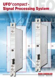
1.2 Mid range antennas<br />
The MIRA 100° was developed for<br />
applications in the area between<br />
near-field <strong>and</strong> far-field. Particular<br />
importance was placed on creating<br />
a compact construction to enable<br />
integration into environments with<br />
limited space. Read ranges of over 2 m<br />
are still possible even with dimensions<br />
of 156 x 126 mm. MIRA also offers<br />
increased selectivity at lower reading<br />
distances compared with conventional<br />
Figure: MID Range<br />
antennas. This antenna design is therefore also suitable for use in<br />
the so-called transition area with a variety of transponder types.<br />
/ 20
1. Product description<br />
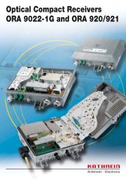
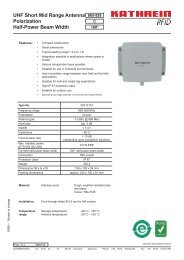
1.3 Wide range antennas<br />
For traditional wide-range applications<br />
with read ranges of over 10 m, Kathrein<br />
offers the two new wide range antenna<br />
models characterised by half widths<br />
of 70° (WIRA 70°) <strong>and</strong> 30° (WIRA<br />
30°). The circular polarization usually<br />
required for <strong>UHF</strong> applications has been<br />
significantly improved compared with<br />
other antennas available on the market.<br />
For the so-called axis ratio, which<br />
is used as a characteristic value for<br />
circular polarization, the two new<br />
models achieve typical values of 1 dB.<br />
If specified at all, the usual value on<br />
the market lies at around 3 dB.<br />
Figure: Wide Range 70°<br />
The improved circularity leads to a significant reduction in the dependence<br />
of the reading results on the position or alignment of the transponder. Great<br />
importance was also placed the front-to-back ratio of the antennas to reduce<br />
the influence of the close (assembly) environment on the antenna properties.<br />
All antennas have an extremely high protection class which guarantees problemfree<br />
use in any environment.<br />
The use of high-quality materials for a long service life <strong>and</strong> high levels of<br />
reliability contribute to the optimal performance provided by the antenna under<br />
even the most challenging of conditions.<br />
Figure: Wide Range 30°<br />
/ 20
1. Product description<br />
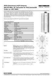
1.4 Antenna type according to read range <strong>and</strong> transponder shape<br />
Antenna type Read range Tag type<br />
Loop tag Hybrid Dipole tag<br />
<strong>LORA</strong><br />
U<strong>LORA</strong><br />
0-10 cm<br />
10-30 cm<br />
MIRA<br />
30-100 cm<br />
> 100 cm<br />
10-30 cm<br />
WIRA 70°<br />
WIRA 30°<br />
30-200 cm<br />
> 200 cm<br />
The correct combination of reader antenna <strong>and</strong> transponder is essential for<br />
every <strong>RFID</strong> application. The correct selection ensures a high read rate <strong>and</strong><br />
reliable operation of the system.<br />
The <strong>LORA</strong> <strong>and</strong> U<strong>LORA</strong> antennas can read loop, hybrid <strong>and</strong> dipole transponders<br />
up to 10 cm <strong>and</strong> offer a very good defined read range.<br />
MIRA can activate loop transponders up to 30 cm, hybrid up to 100 cm <strong>and</strong> dipole<br />
transponders up to several meters.<br />
The WIRA antennas are designed for typical far-field dipole transponders<br />
with read ranges of over 10 m, but they can also read the near-field <strong>and</strong> hybrid<br />
transponders at a short distance.<br />
/ 20
1. Product description<br />
The typical read ranges of the presented antennas can be seen in the following<br />
figure. If WIRA 30° <strong>and</strong> WIRA 70° are operated with the same ERP, the<br />
maximum ranges of the two antennas are equal, although the WIRA 30° has<br />
a higher selectivity.<br />
10m<br />
8m<br />
6m<br />
4m<br />
2m<br />
WIRA 70° 33 ERP<br />
WIRA 30° 33 ERP<br />
MIRA 100° 27 ERP<br />
<strong>LORA</strong>/U<strong>LORA</strong><br />
4m 2m 0 2m 4m<br />
Figure: Read ranges of <strong>LORA</strong>/U<strong>LORA</strong>, MIRA, WIRA 70° <strong>and</strong> WIRA 30°<br />
Note<br />
To achieve the best reading <strong>and</strong> writing results, we recommend operating<br />
the Kathrein <strong>UHF</strong> <strong>RFID</strong> reader antennas exclusively with <strong>UHF</strong> readers from<br />
Kathrein.<br />
/ 20
2. Technical data U<strong>LORA</strong>/<strong>LORA</strong><br />
Type no. U<strong>LORA</strong> <strong>LORA</strong><br />
Order number 52010092 52010084<br />
Frequency range MHz 865-928 865-870<br />
Antenna gain dBi -30 -15<br />
EIFF* ) dB 15 20<br />
VSWR < 1,2 : 1 < 1,2 : 1<br />
Impedance Ω 50 50<br />
Range near-field tags ** ) cm 3 7<br />
Selectivity near-field tags ** ) cm 3 5<br />
Range far-field tags ** ) cm 8 -<br />
Selectivity far-field tags ** ) cm 10 -<br />
Maximum input power *** ) W 1 0,5<br />
Connection TNC socket TNC socket<br />
Protection class IP 67 IP 67<br />
Weight g 110 110<br />
Dimensions (W x H x D) mm 90 x 63 x 31 90 x 63 x 31<br />
Packaging dimensions (approx.) mm 250 x 165 x 50 250 x 165 x 50<br />
*) Effective Isotropic Field Factor (EIFF) shows the field isolation of far-field to near-field<br />
st<strong>and</strong>ardised to an isotropic radiator. The values are determined at a distance of 3 cm<br />
**) Depending on the transmitting power <strong>and</strong> the tag type<br />
***) Complies with EN 302208 <strong>and</strong> EN 50364. Please read the chapters “Kathrein<br />
reader settings” <strong>and</strong> “Compliance with st<strong>and</strong>ards” in these application <strong>notes</strong><br />
/ 20
3. Read range <strong>and</strong> selectivity<br />
The read range <strong>and</strong> selectivity are the most important properties of an <strong>RFID</strong><br />
application. The read range refers to the largest distance at which a tag can<br />
be read <strong>and</strong> selectivity refers to the minimum distance required to clearly<br />
differentiate between two transponders positioned next to each other.<br />
The system properties depend largely on the type of transponder used. The <strong>UHF</strong>-<br />
<strong>RFID</strong> tags can be divided into three main groups: The first group is made up of<br />
small, loop tags (near-field tags) with an average diameter of 2 cm <strong>and</strong> which<br />
mainly couple magnetically with the reader antenna. These transponders have<br />
the smallest ranges, as the magnetic field falls extremely quickly with the distance<br />
from the reader antenna. The second group includes the so-called hybrid tags,<br />
which have a mixed shape somewhere between a loop tag <strong>and</strong> a dipole tag.<br />
These tags can be activated by the reader antenna through the magnetic field,<br />
the electric field or a combination of the two. The final group includes the farfield<br />
tags, which couple mainly via the electrical field. These tags can achieve<br />
ranges of over 10 m.<br />
3.1 Antenna allocation according to tag type<br />
The U<strong>LORA</strong> was developed to fulfil the most challenging dem<strong>and</strong>s with regard to<br />
range <strong>and</strong> selectivity of the tags from all three groups. It is a universal antenna<br />
for a wide variety of low range applications. With this antenna, extremely low<br />
read ranges under 10 cm <strong>and</strong> high selectivity with far-field tags are possible.<br />
It can also read near-field tag at distances of up to 3 cm. In order to significantly<br />
increase the reading distance for near-field tags, the <strong>LORA</strong> was developed for<br />
read ranges of 7 cm with conventional loop transponders. The figure under 3.1<br />
shows the allocation of U<strong>LORA</strong> <strong>and</strong> <strong>LORA</strong> to the different tag types. It is evident<br />
that the U<strong>LORA</strong> is suitable for all three groups, while the <strong>LORA</strong> is particularly<br />
suited for use with loop transponders.<br />
/ 20
3. Read range <strong>and</strong> selectivity<br />
Overview U<strong>LORA</strong> <strong>and</strong> <strong>LORA</strong> according to tag type<br />
Loop tags<br />
(near-field tags)<br />
<strong>LORA</strong><br />
Hybrid tags<br />
Dipole tags<br />
(far-field tags)<br />
U<strong>LORA</strong><br />
3.2 Read range<br />
In order to quantify the read range of U<strong>LORA</strong> <strong>and</strong> <strong>LORA</strong>, the figure under 3.3<br />
shows the relevant read ranges of U<strong>LORA</strong> und <strong>LORA</strong> for different transponder<br />
designs. In each case, all transponders are aligned parallel to the reader antenna.<br />
It is evident that U<strong>LORA</strong> has a very good defined read range for all transponders.<br />
The <strong>LORA</strong>, on the other h<strong>and</strong>, is a special solution for near-field tags with a<br />
significantly larger read range than the U<strong>LORA</strong>.<br />
10 / 20
3. Read range <strong>and</strong> selectivity<br />
3.3 Selectivity<br />
The high selectivity of low range antennas opens up a whole host of new <strong>UHF</strong>-<br />
<strong>RFID</strong> applications which were previously not possible. Both models can record<br />
transponders individually, some of which have distances of less than 5 cm.<br />
This therefore makes them the ideal antennas for Item Level Tagging applications.<br />
Tag type Ultra Low Range antenna Low Range antenna<br />
Loop tags<br />
(near-field tags)<br />
Hybrid tags<br />
Dipole tags<br />
(far-field tags)<br />
Fig. 3.3: Read range of U<strong>LORA</strong> <strong>and</strong> <strong>LORA</strong> according to tag type<br />
11 / 20
4. Kathrein reader settings<br />
The ETSI st<strong>and</strong>ard EN 302 208 defines the maximum effective radiated<br />
power (ERP) for <strong>RFID</strong> systems. According to this st<strong>and</strong>ard, antennas with a<br />
half-width larger than 70° have a maximum ERP power of 27 dBm.<br />
The ERP is converted into output power P C<br />
on the reader as follows:<br />
P C,max<br />
= P ERP,max<br />
- G IC<br />
+ 5.15 + C L<br />
Where<br />
P C,max<br />
:<br />
P ERP,max<br />
:<br />
G IC<br />
:<br />
C L<br />
:<br />
refers to the maximum output power of the reader in dBm,<br />
refers to the maximum effective radiated power of the antenna in dBm,<br />
refers to the circular antenna gain in dBic,<br />
refers to the cable loss in dB.<br />
The U<strong>LORA</strong> <strong>and</strong> <strong>LORA</strong> are universal antennas for low range applications.<br />
They have a gain of less than -15 dBi. The output power of the reader could<br />
therefore be calculated incorrectly <strong>and</strong> be set too high.<br />
According to the data sheet, the maximum input power for the U<strong>LORA</strong> is 30 dBm<br />
<strong>and</strong> 27 dBm for the <strong>LORA</strong>. The following guidelines are intended to act as an aid<br />
in configuring the settings of the Kathrein <strong>UHF</strong> reader.<br />
1. Kathrein reader start demo software<br />
The Kathrein reader start demo software offers users the option of setting<br />
the ERP, the gain <strong>and</strong> the cable attenuation right away without having to<br />
calculate the output power on the reader. As it is impractical with the U<strong>LORA</strong><br />
<strong>and</strong> <strong>LORA</strong> to set the ERP power right away, the user should ensure that<br />
the output power is configured correctly.<br />
If the antenna gain is set to 5.25 dB in the demo software, the ERP is equal<br />
to the output power on the reader. The user should then enter the cable<br />
attenuation.<br />
For example:<br />
An application uses <strong>LORA</strong> with a cable with 0.5 dB attenuation. The<br />
antenna should be operated with the maximum input power of 0.5 W.<br />
The correct settings are shown in the figure Reader Start, Version 1.13:<br />
12 / 20
4. Kathrein reader settings<br />
Figure: Reader Start, Version 1.13<br />
In this case, the output power on the reader is:<br />
P C,max<br />
= 27 dBm – 5.25 dBic + 5.15 + 0.5 dB = 27.4 dBm = 0.55 W<br />
<strong>and</strong> the antenna input power is:<br />
P input power<br />
= 27.4 dBm – 0.5 dB (cable attenuation) = 26.9 dBm = 0.49 W<br />
which corresponds to the power in the data sheet.<br />
2. Kathrein reader comm<strong>and</strong>s<br />
To enable problem-free integration of the Kathrein <strong>UHF</strong> reader in every<br />
application, all settings of the reader can be configured via a “.dll” library.<br />
When setting the output power on the reader, the following comm<strong>and</strong>s should<br />
be taken into account.<br />
CfgidRFInterfaceRFPowerPort1()<br />
CfgidRFInterfaceAntennaGain1()<br />
CfgidRFInterfaceCableLoss1()<br />
For the example from the previous chapter, these functions should be<br />
parametered as follows:<br />
CfgidRFInterfaceRFPowerPort1() with 27 dBm<br />
CfgidRFInterfaceAntennaGain1() with 5.25 dBic<br />
CfgidRFInterfaceCableLoss1() with 0.5 dB<br />
13 / 20
5. Compliance with st<strong>and</strong>ards<br />
As <strong>RFID</strong> systems are radio installations, they fall under the European<br />
Commission directive 1999/5/EC (Radio Equipment <strong>and</strong> Telecommunications<br />
Terminal Equipment R&TTE).<br />
A series of harmonised st<strong>and</strong>ards are in place to prove conformity with the basic<br />
requirements of this directive, which are published in the official journal of the<br />
European Union.<br />
The Kathrein <strong>LORA</strong> <strong>and</strong> U<strong>LORA</strong> are passive antenna structures. It is therefore<br />
the system integrator who is responsible for ensuring compliance with the<br />
st<strong>and</strong>ards – i.e. the person who combines the individual components of<br />
an <strong>RFID</strong> system with each other, in particular the reader <strong>and</strong> antennas.<br />
We therefore strongly recommend acquiring these st<strong>and</strong>ards.<br />
Two important st<strong>and</strong>ards in relation to antennas are (with no claim of<br />
completeness) EN 302208 <strong>and</strong> EN 50364: The first deals with frequency<br />
spectrum issues <strong>and</strong> limits the maximum radiated power, while the EN 50364<br />
addresses the limits regarding exposure of people to electromagnetic fields.<br />
In accordance with EN 50364, compliance is achieved if the defined limit values<br />
of the electrical <strong>and</strong> magnetic field strength are not exceeded at a distance<br />
of 20 cm around the antennas. As the U<strong>LORA</strong> <strong>and</strong> <strong>LORA</strong> have a high field<br />
concentration at near-field <strong>and</strong> extremely reduced antenna gain at far-field,<br />
the electrical, magnetic <strong>and</strong> electromagnetic fields at a distance of 20 cm from<br />
the antenna with the maximum antenna input power specified in the table under<br />
section 2 lie far below the values required for compliance (both for professional<br />
exposure <strong>and</strong> exposure to the general public).<br />
As the usual usage range for both antennas lies under 20 cm, additional<br />
numeric calculations were carried out for the specific absorption rate (SAR). The<br />
calculated SAR values are compared with the basic limit values of EN 50364 -<br />
separated according to professional exposure <strong>and</strong> exposure to the general public,<br />
as well as local exposure to head <strong>and</strong> body or the extremities.<br />
The figure on the right shows a model<br />
of a human h<strong>and</strong> as an example<br />
directly grabbing the antenna during<br />
operation (e.g. access control). The<br />
assumptions made here (such as the<br />
operating mode of the <strong>RFID</strong> system<br />
<strong>and</strong> properties of the human skin)<br />
guarantee a conservative estimation of<br />
the exposure (worst case scenario).<br />
The calculation was also carried out for the most sensitive constellation, i.e. for<br />
the event that members of the general public are permanently located in close<br />
proximity to the antenna with head <strong>and</strong> body. In this constellation with <strong>LORA</strong>, it is<br />
guaranteed that the maximum permitted SAR will not be exceeded with an antenna<br />
input power of up to 0.1 W (20 dBm). With the exception of this special case,<br />
U<strong>LORA</strong> <strong>and</strong> <strong>LORA</strong> can be operated with their maximum specified input power.<br />
14 / 20
5. Compliance with st<strong>and</strong>ards<br />
The table below shows the maximum input powers with which the antennas<br />
can be supplied to ensure that the basic limit values of the SAR are not<br />
exceeded. A difference is made here between the different types of exposure.<br />
Professional exposure<br />
Limit values head <strong>and</strong> body 10 W/kg<br />
Limit values local limbs 20 W/kg<br />
General public<br />
Local limbs exposure<br />
Limit values local limbs 4 W/kg<br />
General public<br />
Head <strong>and</strong> body exposure<br />
Limit values head <strong>and</strong> body 2 W/kg<br />
U<strong>LORA</strong><br />
Pin = 1 W<br />
(30 dBm)<br />
Pin = 1 W<br />
(30 dBm)<br />
Pin = 1 W<br />
(30 dBm)<br />
<strong>LORA</strong><br />
Pin = 0.5 W<br />
(27 dBm)<br />
Pin = 0.5 W<br />
(27 dBm)<br />
Pin = 0.1 W<br />
(20 dBm)<br />
Table: The maximum input power<br />
15 / 20
6. Assembly/attachment<br />
The special properties of low range antennas from Kathrein allow fixing equipment<br />
to be used which was previously impossible with conventional antennas:<br />
The performance of both antennas is not influenced by the assembly<br />
subsurface, meaning that they can also be fixed directly on to metal surfaces<br />
without having to ensure a minimum distance.<br />
Note<br />
When routing the cable, simply ensure that it is not positioned directly in front<br />
of the antenna housing within the read range.<br />
X<br />
<strong>LORA</strong>/<br />
U<strong>LORA</strong><br />
16 / 20
7. Typical applications<br />
1. Pharmaceutical industry<br />
The read range of the low range antennas means that the individual<br />
pharmaceutical products can be selected or distinguished so that the life cycle<br />
of each medication can be monitored from production onwards. As <strong>LORA</strong><br />
couples primarily via the magnetic field, transponders can be positioned directly<br />
on bottles with liquid <strong>and</strong> blister packaging.<br />
Note<br />
In order to achieve optimal performance, we therefore recommend using the<br />
<strong>LORA</strong> in conjunction with loop tags.<br />
2. Access control<br />
Due to the large read area of conventional <strong>UHF</strong> antennas, access control<br />
applications were primarily implemented with HF-<strong>RFID</strong> technology in the<br />
past. The new <strong>UHF</strong>-<strong>RFID</strong> low range antennas from Kathrein can now<br />
also be used for this application.<br />
Note<br />
For this use, we recommend using loop tags in conjunction with the U<strong>LORA</strong>.<br />
These transponders are only read in a defined range by the Kathrein<br />
low range antennas. In this way, both incorrect readings <strong>and</strong> unwanted<br />
monitoring of people are ruled out.<br />
3. Automation industry<br />
Low range antennas can be used for every <strong>RFID</strong> automation application<br />
requiring a precise, defined read range <strong>and</strong> a high selectivity. One particular<br />
benefit here is the option of detecting far-field transponders individually with<br />
the U<strong>LORA</strong> <strong>and</strong> reading the same transponders on other reading stations<br />
with MIRA or WIRA from larger distances in multi-tag operation.<br />
Important!<br />
When using the antennas, comply with the relevant valid regulations in your<br />
country <strong>and</strong> any st<strong>and</strong>ards <strong>and</strong> guidelines valid specifically for the area or<br />
place of use.<br />
17 / 20
8. Technical appendix<br />
8.1 Antenna gain<br />
The gain is the ratio between the radiated power density in the main radiation direction<br />
for the antenna in question <strong>and</strong> a reference antenna with the same supply power.<br />
Reference antennas are isotropic radiators or λ/2 – dipole<br />
Frequent logarithmic tasks:<br />
- dBi: linear gain based on isotropic radiator<br />
- dBd: linear gain based on dipole<br />
- dBic: circular gain based on isotropic radiator<br />
Isotropic radiator<br />
Pin = 1.256 W<br />
Power density at 10 m<br />
Dipole with gain 1.64 (2.15 dBi)<br />
Pin = 1.256 W<br />
Power density at 10 m<br />
Antenna with gain 4 (6dBi)<br />
Pin = 1.256 W<br />
Power density at 10 m<br />
The isotropic radiator is a loss-free point radiator with an even spherical<br />
radiation pattern in all directions. Its power density is distributed evenly over a<br />
sphere with a surface of 4π²r.<br />
The gain of the λ/2 – dipole is 1.64 <strong>and</strong> the power density it produces is 1.64 times<br />
as big.<br />
An example antenna with a gain of 6 dBi achieves a power density 6 dB larger<br />
than that of the isotropic radiator.<br />
18 / 20
8. Technical appendix<br />
If the gain of this antenna is based on the gain of the λ/2 dipole, the gain is shown<br />
in dBb.<br />
The antenna with a gain of 6 dBi, has 6 dBi – 2.15 dBi = 3.85 dBd gain.<br />
The circular polarized gain (dBic) is also 3 dB larger than the gain in dBi.<br />
8.2 ERP: Effective radiated power<br />
Product of the power supplied to a transmitter antenna multiplied by its gain<br />
based on λ/2 dipole.<br />
8.3 EIRP: Effective Isotropically Radiated Power<br />
Product of the power supplied to a transmitter antenna multiplied with its gain<br />
based on the isotropic radiation.<br />
With <strong>UHF</strong>-<strong>RFID</strong>, the maximum ERP is specified by law. When using<br />
antennas with a high gain, the reader power must be reduced accordingly.<br />
This means that the read range doesn’t increase with the antenna<br />
gain – the width of the read range is merely changed.<br />
8.4 Examples – antennas – input power<br />
Europe: ERP power is limited according to EN 302208 to 2 W (33 dBm).<br />
An antenna has a gain of 8.5 dBic<br />
dBic converted to dBi:<br />
8.5 dBic = 8.5 - 3 = 5.5 dBi<br />
dBi converted into dBd:<br />
5.5 dBi = 5.5 - 2.15 = 3.35 dBd<br />
Antenna input power: 33 dBm - 3.35 dBd = 29.65 dBm (0.922 W)<br />
USA: EIRP power is limited according to FCC Part 15 to 4 W (36 dBm).<br />
1. Antenna gain smaller or equal to 6 dBi<br />
Antenna input power is equal to 30 dBm (1 W)<br />
2. Antenna gain larger than 6 dBi (e.g. 7 dBi)<br />
Antenna input power must be reduced: 36 dBm – 7 dBi = 29 dBm (0.794 W)<br />
19 / 20
9. Contact address<br />
Address<br />
Contact<br />
KATHREIN-Werke KG E-mail: rfid@kathrein.de<br />
<strong>RFID</strong>-Systeme Internet: www.kathrein-rfid.de<br />
P.O. Box 100 444<br />
83004 Rosenheim GERMANY<br />
These application <strong>notes</strong> are available on the Internet in German, English <strong>and</strong><br />
French at “www.kathrein.de” → “<strong>RFID</strong> Systems” → “Product overview” →<br />
“<strong>UHF</strong> antenna” under the relevant antenna.<br />
Electronic equipment is not classed as household waste <strong>and</strong> must<br />
be disposed of properly in accordance with Directive 2002/96/EC<br />
OF THE EUROPEAN PARLIAMENT AND OF THE COUNCIL of<br />
27 January 2003 on used electrical <strong>and</strong> electronic equipment.<br />
At the end of its service life, take this device to a designated<br />
public collection point for disposal.<br />
936.3832/-/ZWT/0710/e - Technical data subject to change.<br />
KATHREIN-Werke KG • Anton-Kathrein-Straße 1 - 3 • P.O. Box 100 444 • 83004 Rosenheim • Germany • phone +49 8031 184-0 • Fax +49 8031 184-494
Anwendungshinweis<br />
Deutsch<br />
<strong>RFID</strong>-<strong>UHF</strong>-Antennen<br />
Low Range und Ultra Low Range<br />
(<strong>LORA</strong> und U<strong>LORA</strong>)
Inhalt<br />
Sicherheitshinweise/-infos 3<br />
Zeichenerklärung 3<br />
Allgemeine Sicherheitshinweise 3<br />
1. Produktbeschreibung 4<br />
1.1 Low Range-Antennen 4<br />
1.2 Mid Range-Antennen 4<br />
1.3 Wide Range-Antennen 5<br />
1.4 Antennentyp nach Lesereichweite und Transponderform 6<br />
2. Technische Daten U<strong>LORA</strong>/<strong>LORA</strong> 8<br />
3. Lesereichweite und Selektivität 9<br />
3.1 Antennenzuordnung nach Tag-Arten 9<br />
3.2 Lesereichweite 10<br />
3.3 Selektivität 11<br />
4. Einstellungen des Kathrein-Readers 12<br />
5. Normenkonformität 14<br />
6. Montage/Befestigung 16<br />
7. Typische Applikationen 17<br />
8. Technischer Anhang 18<br />
8.1 Antennen-Gewinn 18<br />
8.2 ERP: Effektive Strahlungsleistung 19<br />
8.3 EIRP: Effektive Isotrope Strahlungsleistung 19<br />
8.4 Beispiele – Antennen – Eingangsleistung 19<br />
9. Kontaktadresse 20<br />
Im Anwendungshinweis verwendete Abkürzungen:<br />
DIN Deutsches Institut für Normung<br />
EIFF<br />
Effective Isotropic Field Factor EIFF zeigt die Feldisolation von<br />
Fernfeld zu Nahfeld normiert auf einen isotropen Kugelstrahler.<br />
EIRP<br />
Effective Isotropically radiated power<br />
Effektive Isotrope Strahlungsleistung<br />
EN<br />
Europäische Norm<br />
ERP<br />
Effective Radiated Power<br />
Effektive Strahlungsleistung<br />
<strong>LORA</strong> Low Range<br />
MIRA Mid Range<br />
<strong>RFID</strong> Radio Frequency Identification<br />
SAR Spezifische Absorptionsrate<br />
<strong>UHF</strong> Ultra High Frequency<br />
U<strong>LORA</strong> Ultra Low Range<br />
WIRA Wide Range<br />
/ 20
Sicherheitshinweise/-infos<br />
Zeichenerklärung<br />
Vorsicht<br />
Hinweis<br />
Gibt eine potentiell gefährliche Situation an,<br />
die bei Nichtbeachtung zu leichten bis schweren<br />
Verletzungen und/oder Geräteschäden führen<br />
kann.<br />
Informationen, die das Verständnis eines<br />
bestimmten Themas und/oder die optimale<br />
Nutzung der Gerätefunktionalität erleichtern.<br />
Allgemeine Sicherheitshinweise<br />
Achtung!<br />
Vor dem Beginn der Installationsarbeiten bzw. vor dem Austausch des Gerätes muss<br />
der mitgelieferte Anwendungshinweis sorgfältig gelesen und sein Inhalt verst<strong>and</strong>en<br />
werden.<br />
Die detaillierten Angaben in den Datenblättern und in diesem Anwendungshinweis<br />
müssen bei der Installation und während des Betriebs sorgfältig eingehalten werden!<br />
Das Installations-Team muss ordnungsgemäß qualifiziert und mit den im jeweiligen<br />
L<strong>and</strong> geltenden Sicherheitsvorschriften vertraut sein.<br />
Der Anschluss, die Einrichtung und die Wartung des Gerätes sowie <strong>and</strong>ere Arbeiten<br />
am Gerät dürfen nur von entsprechend qualifizierten und geschulten Mitarbeitern<br />
durchgeführt werden.<br />
Das Gerät darf nur für den vom Hersteller vorgesehenen Zweck verwendet werden.<br />
Durch unbefugte Änderungen und die Verwendung von Ersatzteilen und Zusatzgeräten,<br />
die nicht vom Hersteller verkauft bzw. empfohlen werden, können Brände,<br />
Stromschläge und Verletzungen verursacht werden. Derartige H<strong>and</strong>lungen führen<br />
daher zum Haftungsausschluss und die Herstellergarantie (Gewährleistung) wird<br />
nichtig.<br />
Für das Gerät gilt die Version der Herstellergarantie (Gewährleistung), die zum Kaufzeitpunkt<br />
gültig war. Für die ungeeignete manuelle oder automatische Einstellung<br />
der Geräteparameter und die unangemessene Verwendung des Gerätes wird keine<br />
Haftung übernommen.<br />
Reparaturen dürfen nur von befugtem Personal durchgeführt werden. Durch Öffnen<br />
des Gerätes und Reparaturversuche gehen alle Garantie-/Gewähr-leistungsansprüche<br />
verloren! Durch unsachgemäße Arbeiten am Gerät kann die elektrische Sicherheit<br />
des Gerätes beeinträchtigt werden.<br />
Der Hersteller haftet nicht für Unfälle, die durch das Öffnen des Gerätes durch<br />
den Benutzer verursacht worden sind!<br />
Bei der Durchführung von Arbeiten am Gerät müssen die geltenden Sicherheitsbestimmungen<br />
eingehalten werden.<br />
/ 20
1. Produktbeschreibung<br />
Die neue Kathrein-Antennenfamilie besteht aus verschiedenen <strong>UHF</strong>-Reader-<br />
Antennen, welche die Anforderungen nahezu jeder <strong>RFID</strong>-Applikation erfüllen können.<br />
Die Antennen sind in drei Produktlinien bezüglich der Lesereichweite unterteilt:<br />
Low Range-, Mid Range- und Wide Range-Antennen.<br />
1.1 Low Range-Antennen<br />
Die Low Range-Antennen stellen das<br />
Highlight der neuen Antennenfamilie<br />
dar. Bei Abmessungen von 90 x 63 mm<br />
verfügen diese Antennen über eine hohe<br />
Feldkonzentration im Nahbereich bei<br />
gleichzeitig extrem reduziertem Antennengewinn<br />
im Fernfeld. Die Antennen<br />
erzielen durch diese Eigenschaften hervorragende<br />
Schreib-/Leseergebnisse<br />
bei Reichweiten bis zu 10 cm mit einer<br />
typischen Selektivität von 5 cm.<br />
Die Low Range-Antennen gibt es in<br />
den Typen <strong>LORA</strong> (Low Range) und<br />
U<strong>LORA</strong> (Ultra Low Range). Die U<strong>LORA</strong><br />
wurde darauf ausgelegt, dipolförmige<br />
Tags („Fernfeld-Tags“) in einer sehr begrenzten<br />
Entfernung zu lesen. Diese<br />
Antenne kann darüber hinaus schleifenförmige<br />
Tags („Nahfeld-Tags“) bis<br />
auf 3 cm ansprechen. Für eine größere<br />
Reichweite wurde die <strong>LORA</strong> entwickelt,<br />
die sich insbesondere für Nahfeld-Tags<br />
eignet. Die Antennenzuordnung nach<br />
Lesereichweite und Transponderform ist<br />
in Kapitel 3 dargestellt.<br />
Abbildung: <strong>LORA</strong><br />
Abbildung: U<strong>LORA</strong><br />
1.2 Mid Range-Antennen<br />
Für Applikationen im Bereich zwischen<br />
Nah- und Fernfeld wurde die MIRA<br />
100° entwickelt. Dabei wurde besonders<br />
auf eine kompakte Bauform für<br />
die Integration in bauraumkritischen<br />
Umgebungen Wert gelegt. Bei Abmessungen<br />
von 156 x 126 mm sind dennoch<br />
Lesereichweiten von mehr als 2 m möglich.<br />
Gleichzeitig besitzt die MIRA bei<br />
geringen Leseabständen gegenüber<br />
herkömmlichen Antennen eine erhöhte<br />
Abbildung: MID Range<br />
Selektivität. Somit eignet sich diese Antennenausführung für die Verwendung im<br />
sogenannten Übergangsbereich mit verschiedenen Transpondertypen.<br />
/ 20
1. Produktbeschreibung<br />
1.3 Wide Range-Antennen<br />
Für die klassischen Fernfeld-Anwendungen<br />
mit Lesereichweiten über 10 m<br />
bringt Kathrein die beiden neuen Wide<br />
Range-Antennentypen auf den Markt,<br />
die sich durch Halbwertsbreiten von<br />
70° (WIRA 70°) und 30° (WIRA 30°) auszeichnen.<br />
Die für <strong>UHF</strong>-Anwendungen<br />
üblicherweise benötigte zirkulare Polarisation<br />
wurde im Vergleich zu den am<br />
Markt verfügbaren Antennen signifikant<br />
verbessert. Bei dem sogenannten Achsverhältnis,<br />
das als Kennwert für die<br />
zirkulare Polarisation verwendet wird,<br />
erzielen die beiden neuen Varianten<br />
Werte von typisch 1 dB. Der marktübliche<br />
Wert liegt, wenn überhaupt spezifiziert,<br />
bei circa 3 dB.<br />
Abbildung: Wide Range 70°<br />
Die verbesserte Zirkularität führt zu einer deutlich reduzierten Abhängigkeit der<br />
Leseergebnisse von Lage oder Ausrichtung der Transponder. Zudem wurde ein<br />
großes Augenmerk auf das Vor-/Rückverhältnis der Antennen gelegt, um Einflüsse<br />
der näheren (Montage-)Umgebung auf die Antenneneigenschaften zu verringern.<br />
Alle Antennen verfügen über eine sehr hohe Schutzklasse, die ihren problemlosen<br />
Einsatz in jeder Umgebung gewährleistet.<br />
Die Verwendung hochwertiger Materialien für eine lange Lebensdauer und hohe Zuverlässigkeit<br />
tragen dazu bei, dass die Antenne unter den härtesten Bedingungen<br />
optimale Leistung bringt.<br />
Abbildung: Wide Range 30°<br />
/ 20
1. Produktbeschreibung<br />
1.4 Antennentyp nach Lesereichweite und Transponderform<br />
Antennentyp<br />
<strong>LORA</strong><br />
U<strong>LORA</strong><br />
Lesereichweite<br />
0-10 cm<br />
Tag-Art<br />
Schleifenförmig Hybrid Dipolartig<br />
10-30 cm<br />
MIRA<br />
30-100 cm<br />
> 100 cm<br />
10-30 cm<br />
WIRA 70°<br />
WIRA 30°<br />
30-200 cm<br />
> 200 cm<br />
Die richtige Kombination von Reader-Antenne und Transponder ist wesentlich für<br />
jede <strong>RFID</strong>-Applikation. Die korrekte Wahl sichert eine hohe Leserate und den zuverlässigen<br />
Betrieb des Systems.<br />
Die <strong>LORA</strong>- und U<strong>LORA</strong>-Antennen können die schleifenförmigen, die Hybrid- und<br />
die dipolartigen Transponder bis zu 10 cm lesen und verfügen über eine sehr gut<br />
definierte Lesereichweite.<br />
Die MIRA kann die schleifenförmigen Transponder bis zu 30 cm ansprechen,<br />
die Hybrid- bis zu 100 cm und die dipolartigen Transponder bis zu mehreren<br />
Metern.<br />
Die WIRA-Antennen sind für die typischen Fernfeld-dipolartigen Transponder mit<br />
Lesereichweiten von über 10 m ausgelegt, sie können aber auch die Nahfeld-<br />
Schleifenförmigen und Hybrid-Transponder bei einer geringen Entfernung lesen.<br />
/ 20
1. Produktbeschreibung<br />
Die typischen Lesereichweiten der vorgestellten Antennen sind in der folgenden<br />
Abbildung zu sehen. Falls WIRA 30° und WIRA 70° mit gleicher ERP betrieben<br />
werden, entsprechen sich die maximalen Reichweiten der beiden Antennen,<br />
wobei die WIRA 30° über die höhere Selektivität verfügt.<br />
10m<br />
8m<br />
6m<br />
4m<br />
2m<br />
WIRA 70° 33 ERP<br />
WIRA 30° 33 ERP<br />
MIRA 100° 27 ERP<br />
<strong>LORA</strong>/U<strong>LORA</strong><br />
4m 2m 0 2m 4m<br />
Abbildung: Lesereichweiten der <strong>LORA</strong>/U<strong>LORA</strong>, MIRA, WIRA 70° und WIRA 30°<br />
Hinweis<br />
Um beste Lese- bzw. Schreibergebnisse zu erzielen, wird empfohlen,<br />
die Kathrein-<strong>UHF</strong>-<strong>RFID</strong>-Reader-Antennen ausschließlich mit den <strong>UHF</strong>-Readern<br />
von Kathrein zu betreiben.<br />
/ 20
2. Technische Daten U<strong>LORA</strong>/<strong>LORA</strong><br />
Typ Nr. U<strong>LORA</strong> <strong>LORA</strong><br />
Bestellnummer 52010092 52010084<br />
Frequenzbereich MHz 865-928 865-870<br />
Antennen-Gewinn dBi -30 -15<br />
EIFF* ) dB 15 20<br />
VSWR < 1,2 : 1 < 1,2 : 1<br />
Impedanz Ω 50 50<br />
Reichweite Nahfeld-Tags ** ) cm 3 7<br />
Selektivität Nahfeld-Tags ** ) cm 3 5<br />
Reichweite Fernfeld-Tags ** ) cm 8 -<br />
Selektivität Fernfeld-Tags ** ) cm 10 -<br />
Max. Eingangsleistung *** ) W 1 0,5<br />
Anschluss TNC-Buchse TNC-Buchse<br />
Schutzklasse IP 67 IP 67<br />
Gewicht g 110 110<br />
Abmessungen (B x H x T) mm 90 x 63 x 31 90 x 63 x 31<br />
Verpackungsabmessungen (ca.) mm 250 x 165 x 50 250 x 165 x 50<br />
*) Effective Isotropic Field Factor (EIFF) zeigt die Feldisolation von Fernfeld zu Nahfeld,<br />
normiert auf einen isotropen Kugelstrahler. Die Werte sind bei 3 cm Abst<strong>and</strong> ermittelt<br />
**) Abhängig von der Sendeleistung und dem Tag-Typ<br />
***) Konform mit EN 302208 und EN 50364. Dazu bitte Kapitel „Einstellungen Kathrein-<br />
Reader“ und „Normen-Konformität“ in diesem Anwendungshinweis beachten<br />
/ 20
3. Lesereichweite und Selektivität<br />
Die Lesereichweite und die Selektivität sind die wichtigsten Eigenschaften einer<br />
<strong>RFID</strong>-Applikation. Die Lesereichweite beschreibt die größte Entfernung, in der ein<br />
Tag gelesen werden kann und die Selektivität gibt den erforderlichen Mindestabst<strong>and</strong><br />
zur eindeutigen Unterscheidung zweier nebenein<strong>and</strong>er liegender Transponder an.<br />
Die Systemeigenschaften hängen stark vom verwendeten Transpondertyp ab.<br />
Die <strong>UHF</strong>-<strong>RFID</strong>-Tags können in drei prinzipielle Gruppen unterteilt werden: Die erste<br />
Gruppe besteht aus kleinen schleifenförmigen Tags (Nahfeld-Tags), die einen durchschnittlichen<br />
Durchmesser von 2 cm haben und überwiegend magnetisch mit der<br />
Reader-Antenne koppeln. Diese Transponder verfügen über die kleinsten Reichweiten,<br />
da das magnetische Feld sehr schnell mit der Entfernung von der Reader-<br />
Antenne abfällt. Zu der zweiten Gruppe gehören die sogenannten Hybrid-Tags,<br />
die eine Mischform zwischen schleifenförmigen und dipolartigen Tags darstellen.<br />
Diese Tags können von der Reader-Antenne durch das magnetische Feld, das elektrische<br />
Feld oder durch Kombination der beiden angesprochen werden. Die letzte<br />
Gruppe umfasst die dipolartigen Tags (Fernfeld-Tags), die überwiegend über das<br />
elektrische Feld koppeln. Hier sind Reichweiten von mehr als 10 m möglich.<br />
3.1 Antennenzuordnung nach Tag-Arten<br />
Die U<strong>LORA</strong> wurde entwickelt, um die härtesten Anforderungen bezüglich Reichweite<br />
und Selektivität der Tags aller drei Gruppen zu erfüllen. Sie stellt dabei eine universelle<br />
Antenne für viele Low Range-Anwendungen dar. Mit dieser Antenne sind sehr<br />
geringe Leseabstände unter 10 cm und hohe Selektivität mit Fernfeld-Tags möglich.<br />
Darüber hinaus können mit ihr auch Nahfeld-Tags bis zu einer Entfernung von 3 cm<br />
gelesen werden. Um die Leseentfernung für die Nahfeld-Tags deutlich zu vergrößern,<br />
wurde die <strong>LORA</strong> entwickelt, die eine Lesereichweite von 7 cm mit h<strong>and</strong>elsüblichen<br />
schleifenförmigen Transpondern aufweist. Die Abbildung unter 3.1 zeigt die Zuordnung<br />
von U<strong>LORA</strong> und <strong>LORA</strong> zu den verschieden Tag-Arten. Es ist zu erkennen,<br />
dass die U<strong>LORA</strong> für alle drei Gruppen geeignet ist, während sich die <strong>LORA</strong> besonders<br />
für die Verwendung mit schleifenförmigen Transpondern auszeichnet.<br />
/ 20
3. Lesereichweite und Selektivität<br />
Übersicht U<strong>LORA</strong> und <strong>LORA</strong> nach Tag-Arten<br />
SchleifenförmigeTags<br />
(Nahfeld-Tags)<br />
<strong>LORA</strong><br />
Hybrid-Tags<br />
Dipolartige Tags<br />
(Fernfeld-Tags)<br />
U<strong>LORA</strong><br />
3.2 Lesereichweite<br />
Um die Lesereichweite von U<strong>LORA</strong> und <strong>LORA</strong> zu quantifizieren, sind in der Abbildung<br />
unter 3.3 die jeweiligen Lesebereiche von U<strong>LORA</strong> und <strong>LORA</strong> für verschiedene<br />
Transponderausführungen dargestellt. Die Ausrichtung aller Transponder ist dabei<br />
parallel zur Reader-Antenne.<br />
Es ist zu bemerken, dass die U<strong>LORA</strong> einen sehr gut definierten Lesebereich für alle<br />
Transponder aufweist. Die <strong>LORA</strong> dagegen stellt eine Speziallösung für Nahfeld-Tags,<br />
mit einer deutlich größeren Lesereichweite als die U<strong>LORA</strong>, dar.<br />
10 / 20
3. Lesereichweite und Selektivität<br />
3.3 Selektivität<br />
Die hohe Selektivität der Low Range-Antennen eröffnet die Möglichkeit einer Reihe<br />
neuer <strong>UHF</strong>-<strong>RFID</strong>-Anwendungen, die vorher nicht realisierbar waren. Die beiden Varianten<br />
können Transponder, die Abstände von teilweise weniger als 5 cm aufweisen,<br />
einzeln erfassen. Sie stellen somit die idealen Antennen für Item Level Tagging-<br />
Anwendungen dar.<br />
Tag-Art Ultra Low Range-Antenne Low Range-Antenne<br />
SchleifenförmigeTags<br />
(Nahfeld-Tags)<br />
Hybrid-Tags<br />
Dipolartige Tags<br />
(Fernfeld-Tags)<br />
Abbildung 3.3: Lesebereich von U<strong>LORA</strong> und <strong>LORA</strong> nach Tag-Arten<br />
11 / 20
4. Einstellungen des Kathrein-Readers<br />
Die ETSI-Norm EN 302 208 definiert die maximale äquivalente abgestrahlte Leistung<br />
(ERP) bei den <strong>RFID</strong>-Systemen. Laut dieser Norm ist für Antennen mit einer Halbwertsbreite<br />
größer 70° die maximale ERP-Leistung 27 dBm.<br />
Die ERP wird folgendermaßen in Ausgangsleistung P C<br />
am Reader umgerechnet:<br />
P C,max<br />
= P ERP,max<br />
- G IC<br />
+ 5,15 + C L<br />
Hierbei bezeichnet:<br />
P C,max<br />
:<br />
die maximale Ausgangsleistung des Readers in dBm,<br />
P ERP,max<br />
: die maximale effektiv abgestrahlte Leistung der Antenne in dBm,<br />
G IC<br />
:<br />
den zirkularen Antennengewinn in dBic,<br />
C L<br />
:<br />
den Kabelverlust in dB.<br />
Die U<strong>LORA</strong> und die <strong>LORA</strong> sind universelle Antennen für Low Range-Anwendungen.<br />
Sie verfügen über einen Gewinn, der kleiner -15 dBi ist. Auf Grund dessen könnte<br />
die Ausgangsleistung des Readers nicht richtig berechnet und dadurch zu hoch eingestellt<br />
werden.<br />
Laut Datenblatt ist die maximale Eingangsleistung für die U<strong>LORA</strong> 30 dBm und für<br />
die <strong>LORA</strong> 27 dBm. Die folgenden Richtlinien sollten als Hilfsmittel dienen, um die<br />
Einstellungen des Kathrein-<strong>UHF</strong>-Readers richtig zu konfigurieren.<br />
1. Kathrein-Reader-Start Demo-Software<br />
Die Kathrein-Reader-Start Demo-Software bietet dem Nutzer die Möglichkeit<br />
gleich die ERP, den Gewinn und die Kabeldämpfung einzustellen, ohne die Notwendigkeit,<br />
selbst die Ausgangsleistung am Reader zu kalkulieren. Da es bei der<br />
U<strong>LORA</strong> und <strong>LORA</strong> unpraktisch ist, gleich die ERP-Leistung einzustellen, sollte<br />
der Nutzer sicherstellen, dass die Ausgangsleistung richtig konfiguriert ist.<br />
Wenn der Antennen-Gewinn in der Demo-Software mit 5,25 dB eingestellt ist,<br />
ist die ERP gleich die Ausgangsleistung am Reader. Der Nutzer sollte nur noch<br />
die Kabeldämpfung eingeben.<br />
Beispiel:<br />
Eine Applikation nutzt die <strong>LORA</strong> mit einem Kabel mit 0,5 dB Dämpfung.<br />
Die Antenne sollte mit der maximalen Eingangsleistung von 0,5 W betrieben<br />
werden. Die richtigen Einstellungen sind in der Abbildung Reader-Start,<br />
Version 1.13 gezeigt:<br />
12 / 20
4. Einstellungen des Kathrein-Readers<br />
Abbildung: Reader-Start, Version 1.13<br />
Im diesem Fall ist die Ausgangsleistung am Reader:<br />
P C,max<br />
= 27 dBm – 5,25 dBic + 5,15 + 0,5 dB = 27,4 dBm = 0,55 W<br />
und die Antenneneingangsleistung ist:<br />
P Eingangsleistung<br />
= 27,4 dBm – 0,5 dB (Kabeldämpfung) = 26,9 dBm = 0,49 W<br />
was der Leistung vom Datenblatt entspricht.<br />
2. Kathrein-Reader-Befehle<br />
Um die problemlose Integration des Kathrein-<strong>UHF</strong>-Readers in jeder Applikation<br />
zu ermöglichen, können alle Einstellungen des Readers über eine „.dll“-Bibliothek<br />
konfiguriert werden.<br />
Bei der Einstellung der Ausgangsleistung am Reader sollten die folgenden<br />
Befehle beachtet werden.<br />
CfgidRFInterfaceRFPowerPort1()<br />
CfgidRFInterfaceAntennaGain1()<br />
CfgidRFInterfaceCableLoss1()<br />
Für das Beispiel von dem vorherigen Unterkapitel sollten diese Funktionen so<br />
parametriert werden:<br />
CfgidRFInterfaceRFPowerPort1() mit 27 dBm<br />
CfgidRFInterfaceAntennaGain1() mit 5,25 dBic<br />
CfgidRFInterfaceCableLoss1() mit 0,5 dB<br />
13 / 20
5. Normenkonformität<br />
Da es sich bei <strong>RFID</strong>-Systemen um Funkanlagen h<strong>and</strong>elt, fallen diese u. a. unter die<br />
Richtlinie 1999/5/EG der Europäischen Kommission (Funkanlagen und Telekommunikationsendeinrichtungen<br />
R&TTE).<br />
Zum Nachweis der Konformität mit den grundlegenden Anforderungen dieser Richtlinie<br />
existieren eine Reihe harmonisierter Normen, die im Amtsblatt der Europäischen<br />
Union veröffentlicht werden.<br />
Die Kathrein <strong>LORA</strong> und U<strong>LORA</strong> sind passive Antennenstrukturen. Verantwortlich<br />
für die Einhaltung der Normen ist von daher der Systemintegrator – also derjenige,<br />
der die Einzelkomponenten eines <strong>RFID</strong>-Systems, insbesondere Reader und Antennen,<br />
mitein<strong>and</strong>er verbindet. Es wird von daher ausdrücklich empfohlen, sich diese<br />
Normen zu beschaffen.<br />
Zwei wichtige Normen im Zusammenspiel mit den Antennen sind (ohne Anspruch<br />
auf Vollständigkeit) EN 302208 und EN 50364: Erstere beh<strong>and</strong>elt Funkspektrumangelegenheiten<br />
und limitiert die maximal abgestrahlte Leistung, während sich die<br />
EN 50364 mit der Begrenzung der Exposition von Personen gegenüber elektromagnetischen<br />
Feldern beschäftigt.<br />
Gemäß EN 50364 ist Konformität gegeben, sofern in einem Abst<strong>and</strong> von 20 cm um<br />
die Antennen festgelegte Grenzwerte der elektrischen und magnetischen Feldstärke<br />
nicht überschritten werden. Da die U<strong>LORA</strong> und <strong>LORA</strong> über eine hohe Feldkonzentration<br />
im Nahbereich bei gleichzeitig extrem reduziertem Antennengewinn im Fernfeld<br />
verfügen, liegen die elektrischen, magnetischen und elektromagnetischen Felder im<br />
Abst<strong>and</strong> von 20 cm von der Antenne mit den jeweils in der Tabelle aus Abschnitt 2<br />
spezifizierten maximalen Antenneneingangsleistungen weit unter den für die Konformität<br />
geforderten Werten (sowohl für berufliche Exposition als auch für die Exposition<br />
der Allgemeinbevölkerung).<br />
Da der übliche Einsatzbereich beider Antennen unter 20 cm liegt, wurden zusätzlich<br />
numerische Berechnungen der spezifischen Absorptionsrate (SAR) durchgeführt.<br />
Die ermittelten SAR-Werte werden mit den Basisgrenzwerten der EN 50364 - unterschieden<br />
nach beruflicher Exposition und Exposition der Allgemeinbevölkerung sowie<br />
nach lokaler Exposition von Kopf und Rumpf bzw. der Extremitäten - verglichen.<br />
Die Abbildung rechts zeigt dazu ein<br />
exemplarisches Modell einer menschlichen<br />
H<strong>and</strong>, die eine sich im Betrieb<br />
befindliche Antenne direkt umfasst (z. B.<br />
Zutrittskontrolle). Die dabei zu Grunde<br />
gelegten Annahmen (wie z. B. Betriebsart<br />
des <strong>RFID</strong>-Systems und Eigenschaften<br />
des menschlichen Gewebes) gewährleisten<br />
eine konservative Abschätzung der<br />
Exposition (Worst Case-Szenario).<br />
Die Berechnung wurde auch für die empfindlichste Konstellation durchgeführt,<br />
nämlich für den Fall, dass sich Mitglieder der allgemeinen Bevölkerung mit Kopf oder<br />
Rumpf dauerhaft in unmittelbarer Nähe der Antenne aufhalten. In dieser Konstellation<br />
ist bei der <strong>LORA</strong> die Unterschreitung der maximal erlaubten SAR mit einer<br />
14 / 20
5. Normenkonformität<br />
Antenneneingangsleistung von bis zu 0,1 W (20 dBm) sichergestellt. Bis auf diesen<br />
Spezialfall können sowohl U<strong>LORA</strong> als auch <strong>LORA</strong> mit ihrer maximal spezifizierten<br />
Eingangsleistung betrieben werden.<br />
Die Tabelle unten zeigt die maximalen Eingangsleistungen mit der die Antennen gespeist<br />
werden dürfen, um sicherzustellen, dass die Basisgrenzwerte der SAR nicht<br />
überschritten werden. Dabei wird zwischen den verschiedenen Arten der Exposition<br />
unterschieden.<br />
Berufliche Exposition<br />
Grenzwerte Kopf und Rumpf 10 W/kg<br />
Grenzwerte Lokale Gliedmaßen 20 W/kg<br />
Allgemeine Bevölkerung<br />
Lokale Gliedmaßen Exposition<br />
Grenzwerte Lokale Gliedmaßen 4 W/kg<br />
Allgemeine Bevölkerung<br />
Kopf und Rumpf Exposition<br />
Grenzwerte Kopf und Rumpf 2 W/kg<br />
U<strong>LORA</strong><br />
Pin = 1 W<br />
(30 dBm)<br />
Pin = 1 W<br />
(30 dBm)<br />
Pin = 1 W<br />
(30 dBm)<br />
<strong>LORA</strong><br />
Pin = 0,5 W<br />
(27 dBm)<br />
Pin = 0,5 W<br />
(27 dBm)<br />
Pin = 0,1 W<br />
(20 dBm)<br />
Tabelle: Die maximalen Eingangsleistungen<br />
15 / 20
6. Montage/Befestigung<br />
Die besonderen Eigenschaften der Low Range-Antennen von Kathrein ermöglichen<br />
Befestigungsvorrichtungen, die bei herkömmlichen Antennen nicht vorstellbar sind:<br />
Die Performance beider Antennen wird vom Montageuntergrund nicht beeinflusst,<br />
sodass sie auch direkt auf metallischen Oberflächen befestigt werden<br />
können, ohne einen Mindestabst<strong>and</strong> berücksichtigen zu müssen.<br />
Hinweis<br />
Bei der Kabelführung muss lediglich darauf geachtet werden, dass das Kabel<br />
nicht direkt vor dem Gehäuse der Antenne innerhalb des Lesebereichs verlegt<br />
wird.<br />
X<br />
<strong>LORA</strong>/<br />
U<strong>LORA</strong><br />
16 / 20
7. Typische Applikationen<br />
1. Pharmaindustrie<br />
Der Lesebereich der Low Range-Antennen ermöglicht das Selektieren bzw. das<br />
Unterscheiden von einzelnen Pharma-Artikeln, sodass der Lebenszyklus jedes<br />
Medikamentes von der Produktion an verfolgt werden kann. Da die <strong>LORA</strong> primär<br />
über das magnetische Feld koppelt, können hier Transponder direkt auf Flaschen<br />
mit Flüssigkeiten und Blisterverpackungen positioniert werden.<br />
Hinweis<br />
Zur Erzielung einer optimalen Performance wird daher der Einsatz der <strong>LORA</strong><br />
zusammen mit schleifenförmigen Tags empfohlen.<br />
2. Zutrittskontrollen<br />
Aufgrund des großen Lesebereichs typischer <strong>UHF</strong>-Antennen wurden in der<br />
Vergangenheit Zutrittskontrollanwendungen primär mit der HF-<strong>RFID</strong>-Technik realisiert.<br />
Die neuen <strong>UHF</strong>-<strong>RFID</strong>-Low Range-Antennen von Kathrein ermöglichen nun<br />
auch diese Applikation.<br />
Hinweis<br />
Es wird dafür der Einsatz schleifenförmiger Tags in Verbindung mit der<br />
U<strong>LORA</strong> empfohlen. Diese Transponder werden nur in einem definierten<br />
Bereich von den Kathrein-Low Range-Antennen gelesen. Auf diese<br />
Weise werden sowohl Fehllesungen als auch eine unerwünschte<br />
Personenüberwachung ausgeschlossen.<br />
3. Automatisierungs-Industrie<br />
Bei jeder <strong>RFID</strong>-Automatisierungs-Applikation, die einen präzise definierten<br />
Lesebereich und eine hohe Selektivität erfordert, können die Low Range-Antennen<br />
eingesetzt werden. Sehr vorteilhaft hier ist die Möglichkeit, Fernfeld-Transponder<br />
mit der U<strong>LORA</strong> einzeln zu detektieren und an <strong>and</strong>eren Lesestationen die<br />
selben Transponder mit einer MIRA oder WIRA aus größeren Entfernungen im<br />
Multi-Tag-Betrieb zu lesen.<br />
Achtung!<br />
Beachten Sie beim Einsatz der Antennen die jeweils geltenden L<strong>and</strong>esvorschriften<br />
und evtl. speziell für das Einsatzgebiet bzw. den Einsatzort geltende<br />
Normen und Richtlinien.<br />
17 / 20
8. Technischer Anhang<br />
8.1 Antennen-Gewinn<br />
Der Gewinn ist das Verhältnis der Strahlungsleistungsdichten in Hauptstrahlrichtung<br />
der betrachteten Antenne und einer Referenzantenne bei gleicher Speiseleistung.<br />
Referenzantennen sind Isotroper-Kugelstrahler oder λ/2 – Dipol<br />
Häufige logarithmische Angaben:<br />
- dBi: linearer Gewinn bezogen auf isotropen Kugelstrahler<br />
- dBd: linearer Gewinn bezogen auf Dipol<br />
- dBic: zirkularer Gewinn bezogen auf isotropen Kugelstrahler<br />
Der isotrope Kugelstrahler ist ein verlustloser punktförmiger Strahler mit kugelförmiger<br />
Strahlungscharakteristik gleichmäßig in alle Raumrichtungen. Seine Leistungsdichte<br />
ist gleichmäßig über einer Sphäre mit Fläche von 4π²r verteilt.<br />
Der Gewinn des λ/2 – Dipols ist 1,64 und die Leistungsdichte, die es<br />
produziert, ist 1,64 mal größer.<br />
Eine Beispielantenne mit Gewinn von 6 dBi erzielt 6 dB größer Leistungsdichte als<br />
die von dem Kugelstrahler.<br />
18 / 20
8. Technischer Anhang<br />
Wenn der Gewinn dieser Antenne auf dem Gewinn des λ/2-Dipols bezogen ist,<br />
ergibt sich der Gewinn in dBb.<br />
Die Antenne, mit Gewinn 6 dBi, hat 6 dBi – 2,15 dBi = 3,85 dBd Gewinn.<br />
Zusätzlich ist der zirkulare polarisierte Gewinn (dBic) 3 dB größer als der Gewinn<br />
in dBi.<br />
8.2 ERP: Effektive Strahlungsleistung<br />
Produkt der in eine Sendeantenne eingespeisten Leistung multipliziert mit ihrem auf<br />
den λ/2-Dipol bezogenen Gewinn.<br />
8.3 EIRP: Effektive Isotrope Strahlungsleistung<br />
Produkt der in eine Sendeantenne eingespeisten Leistung, multipliziert mit ihrem auf<br />
den isotropen Kugelstrahler bezogenen Gewinn.<br />
Bei <strong>UHF</strong>-<strong>RFID</strong> ist die maximale ERP gesetzlich festgelegt. Bei Einsatz von<br />
Antennen mit hohem Gewinn muss folglich die Reader-Leistung entsprechend<br />
reduziert werden. Die Lesereichweite steigt somit nicht mit dem Antennengewinn<br />
an – lediglich die Breite des Lesebereichs wird verändert.<br />
8.4 Beispiele – Antennen – Eingangsleistung<br />
Europa: ERP-Leistung ist laut EN 302208 auf 2 W (33 dBm) begrenzt.<br />
Eine Antenne hat Gewinn 8,5 dBic<br />
Umrechnung von dBic in dBi:<br />
8,5 dBic = 8,5 - 3 = 5,5 dBi<br />
Umrechnung von dBi in dBd:<br />
5,5 dBi = 5,5 - 2,15 = 3,35 dBd<br />
Antenne-Eingangsleistung: 33 dBm - 3,35 dBd = 29,65 dBm (0,922 W)<br />
USA: EIRP-Leistung ist laut FCC Part 15 auf 4 W (36 dBm) begrenzt.<br />
1. Antennen-Gewinn kleiner oder gleich 6 dBi<br />
Antennen-Eingangsleistung ist gleich 30 dBm (1 W)<br />
2. Antennen-Gewinn größer 6 dBi (z. B. 7 dBi)<br />
Antennen-Eingangsleistung muss reduziert werden: 36 dBm – 7 dBi = 29 dBm<br />
(0.794 W)<br />
19 / 20
9. Kontaktadresse<br />
Anschrift<br />
Kontakt<br />
KATHREIN-Werke KG E-Mail: rfid@kathrein.de<br />
<strong>RFID</strong>-Systeme Internet: www.kathrein-rfid.de<br />
Postfach 100 444<br />
D-83004 Rosenheim<br />
Dieser Anwendungshinweis ist im Internet in deutscher, englischer und französischer<br />
Sprache unter „www.kathrein.de“ → „<strong>RFID</strong> Systeme“ → „Produktübersicht“<br />
→ „<strong>UHF</strong> Antennen“ unter der jeweiligen Antenne verfügbar.<br />
Elektronische Geräte gehören nicht in den Hausmüll, sondern müssen<br />
gemäß Richtlinie 2002/96/EG DES EUROPÄISCHEN PARLAMENTS<br />
UND DES RATES vom 27. Januar 2003 über Elektro- und Elektronik-<br />
Altgeräte fachgerecht entsorgt werden.<br />
Bitte geben Sie dieses Gerät am Ende seiner Verwendung zur<br />
Entsorgung an den dafür vorgesehenen öffentlichen Sammelstellen<br />
ab.<br />
936.3832/-/ZWT/0710/d - Technische Änderungen vorbehalten!<br />
KATHREIN-Werke KG • Anton-Kathrein-Straße 1 - 3 • Postfach 100444 • 83004 Rosenheim • Deutschl<strong>and</strong> • Telefon +49 8031184-0 • Fax +49 8031184-494
Notice d’utilisation<br />
Français<br />
Antennes <strong>RFID</strong> <strong>UHF</strong><br />
Low Range et Ultra Low Range<br />
(<strong>LORA</strong> et U<strong>LORA</strong>)
Contenu<br />
Consignes de sécurité/informations 3<br />
Explication des symboles 3<br />
Consignes générales de sécurité 3<br />
1. Description du produit 4<br />
1.1 Antennes Low Range 4<br />
1.2 Antennes Mid Range 4<br />
1.3 Antennes Wide Range 5<br />
1.4 Type d’antenne en fonction de la portée de lecture et de la forme du<br />
transpondeur 6<br />
2. Caractéristiques techniques U<strong>LORA</strong>/<strong>LORA</strong> 8<br />
3. Portée de lecture et sélectivité 9<br />
3.1 Correspondance entre les antennes et les types de tags 9<br />
3.2 Portée de lecture 10<br />
3.3 Sélectivité 11<br />
4. Réglages du Reader Kathrein 12<br />
5. Conformité aux normes 14<br />
6. Montage/fixation 16<br />
7. <strong>Application</strong>s typiques 17<br />
8. Annexe technique 18<br />
8.1 Gain d'antenne 18<br />
8.2 ERP : puissance de rayonnement effective 19<br />
8.3 EIRP : puissance d’émission isotrope effective 19<br />
8.4 Exemples – antennes – puissance d’entrée 19<br />
9. Adresse de contact 20<br />
Abréviations utilisées dans cette notice :<br />
DIN Deutsches Institut für Normung (Institut allem<strong>and</strong> de normalisation)<br />
EIFF<br />
Effective Isotropic Field Factor, indique l'isolation entre le champ lointain<br />
et le champ proche normée sur un émetteur sphérique isotrope.<br />
EIRP<br />
Effective Isotropically radiated power<br />
Puissance de rayonnement isotrope effective<br />
EN Norme européenne<br />
ERP<br />
Effective Radiated Power<br />
Puissance de rayonnement effective<br />
<strong>LORA</strong> Low Range<br />
MIRA Mid Range<br />
<strong>RFID</strong> Radio Frequency Identification<br />
SAR Taux d’absorption spécifique<br />
<strong>UHF</strong> Ultra High Frequency<br />
U<strong>LORA</strong> Ultra Low Range<br />
WIRA Wide Range<br />
/ 20
Consignes de sécurité/informations<br />
Explication des symboles<br />
Prudence !<br />
Remarque<br />
Signale une situation potentiellement dangereuse,<br />
susceptible d’occasionner des blessures<br />
légères à graves et/ou des dommages sur<br />
l’appareil.<br />
Informations facilitant la compréhension d’un<br />
sujet précis et/ou la bonne utilisation des<br />
fonctions de l’appareil.<br />
Consignes générales de sécurité<br />
Attention !<br />
Avant de commencer les opérations d’installation ou de remplacer l'appareil, il est<br />
impératif d’avoir lu attentivement et compris la notice d’utilisation fournie.<br />
Les indications détaillées qui figurent dans les fiches techniques et dans la présente<br />
notice d’utilisation doivent être soigneusement respectées lors de l'installation et<br />
de l'utilisation !<br />
Le personnel d’installation doit être dûment qualifié et être familiarisé avec les<br />
réglementations de sécurité en vigueur dans le pays.<br />
Le raccordement, l’installation et l’entretien de l’appareil de même que les autres<br />
travaux sur celui-ci ne doivent être effectués que par des personnes qualifiées et<br />
formées.<br />
L’appareil ne doit être utilisé que dans le but prévu par le fabricant.<br />
Les modifications effectuées sans autorisation et l’utilisation de pièces de rechange<br />
et d’appareils additionnels non vendus ou recomm<strong>and</strong>és par le fabricant peuvent<br />
être à l’origine d’incendies, d’électrocutions et de blessures. Elles entraînent par<br />
conséquent l’annulation de la responsabilité du fabricant et de la garantie.<br />
L'appareil est couvert par la version de la garantie qui était en vigueur au moment<br />
de l'achat. Le fabricant décline toute responsabilité en cas de réglage manuel ou<br />
automatique inadéquat des paramètres de l'appareil et d'utilisation incorrecte de<br />
l'appareil.<br />
Les réparations doivent être effectuées uniquement par un personnel autorisé.<br />
L’ouverture de l’appareil et les tentatives de réparation annulent tous droits de<br />
garantie ! Les interventions non conformes effectuées sur l’appareil peuvent porter<br />
atteinte à sa sécurité électrique.<br />
Le fabricant décline toute responsabilité pour les accidents occasionnés par<br />
l’ouverture de l’appareil par l’utilisateur !<br />
Les travaux doivent être effectués en respect des consignes de sécurité en vigueur.<br />
/ 20
1. Description du produit<br />
La nouvelle gamme d’antennes Kathrein comprend différentes antennes<br />
Reader <strong>UHF</strong>, capables de remplir les exigences de pratiquement toute application<br />
<strong>RFID</strong>. Les antennes sont subdivisées en trois séries, suivant la portée de lecture<br />
du lecteur : antennes Low Range, Mid Range et Wide Range.<br />
1.1 Antennes Low Range<br />
Les antennes Low Range se placent<br />
au sommet de la nouvelle gamme<br />
d’antennes. Ces antennes mesurant<br />
90 x 63 mm offrent une concentration de<br />
champ élevée en zone proche ainsi qu’un<br />
gain extrêmement réduit en champ lointain.<br />
Grâce à ces propriétés, les antennes<br />
offrent d'excellents résultats de lecture/<br />
écriture pour des portées jusqu'à 10 cm,<br />
avec une sélectivité typique de 5 cm.<br />
Les antennes Low Range existent en version<br />
<strong>LORA</strong> (Low Range) et U<strong>LORA</strong> (Ultra<br />
Low Range). L'U<strong>LORA</strong> a été conçue<br />
pour lire des tags dipolaires (« tags de<br />
champ lointain ») à une distance très<br />
courte. En outre, cette antenne peut<br />
également communiquer avec des tags<br />
en forme de boucle (« tags de champ<br />
proche ») jusqu'à 3 cm. La <strong>LORA</strong> a été<br />
développée pour une portée supérieure<br />
et convient spécialement aux tags de<br />
champ proche. La correspondance des<br />
antennes en fonction de la portée de<br />
lecture et de la forme du transpondeur<br />
est représentée au chapitre 3.<br />
Figure : <strong>LORA</strong><br />
Figure : U<strong>LORA</strong><br />
1.2 Antennes Mid Range<br />
La MIRA 100° a été développée pour les<br />
applications entre le champ proche et le<br />
champ lointain. L'accent a été mis sur<br />
une structure compacte afin de permettre<br />
l'intégration dans des environnements où<br />
peu de place est disponible. Malgré les dimensions<br />
de 156 x 126 mm, des portées<br />
de lecture de plus de 2 m sont toutefois<br />
possibles. Parallèlement aux distances de<br />
lecture réduites, la MIRA possède une sélectivité<br />
supérieure à celle des antennes<br />
Figure : MID Range<br />
conventionnelles. Pour cette raison, ce type d'antenne convient particulièrement pour<br />
les applications dans la plage dite de transition avec différents types de transpondeurs.<br />
/ 20
1. Description du produit<br />
1.3 Antennes Wide Range<br />
Pour les applications classiques en<br />
champ lointain avec des portées de<br />
lecture de plus de 10 m, Kathrein<br />
met sur le marché les deux nouveaux<br />
types d’antennes Wide Range, qui se<br />
distinguent par des largeurs de lobe<br />
de 70° (WIRA 70°) et 30° (WIRA 30°).<br />
La polarisation circulaire généralement<br />
nécessaire pour les applications <strong>UHF</strong> a<br />
été améliorée de façon significative par<br />
rapport aux antennes disponibles sur<br />
le marché. Pour le « rapport d’axe »,<br />
qui sert de valeur caractéristique pour<br />
la polarisation circulaire, les deux<br />
nouvelles variantes atteignent des<br />
valeurs typiques de 1 dB. La valeur<br />
habituellement rencontrée, si tant<br />
est qu’elle soit communiquée, est<br />
d’environ 3 dB.<br />
Figure : Wide Range 70°<br />
La circularité améliorée entraîne une réduction sensible de la dépendance<br />
entre les résultats de lecture et la position ou l'orientation des transpondeurs.<br />
Une gr<strong>and</strong>e attention a également été accordée au rapport avant/arrière des<br />
antennes, afin de réduire l'influence de l’environnement de montage proche sur les<br />
propriétés des antennes.<br />
Toutes les antennes possèdent une classe de protection très élevée, ce qui<br />
permet de les utiliser sans problème dans n’importe quel environnement.<br />
L’utilisation de matières de qualité assure une longue durée de vie et une gr<strong>and</strong>e<br />
fiabilité et permet aux antennes de fournir les meilleures performances dans les<br />
conditions les plus difficiles.<br />
Figure : Wide Range 30°<br />
/ 20
1. Description du produit<br />
1.4 Type d’antenne en fonction de la portée de lecture et de la forme<br />
du transpondeur<br />
Type<br />
d’antenne<br />
Portée de<br />
lecture<br />
En forme de<br />
boucle<br />
Type de tag<br />
Hybride<br />
Dipolaire<br />
<strong>LORA</strong><br />
U<strong>LORA</strong><br />
0-10 cm<br />
10-30 cm<br />
MIRA<br />
30-100 cm<br />
> 100 cm<br />
10-30 cm<br />
WIRA 70°<br />
WIRA 30°<br />
30-200 cm<br />
> 200 cm<br />
La bonne combinaison entre antenne Reader et transpondeur est essentielle<br />
dans toute application <strong>RFID</strong>. Un bon choix assure un taux de lecture élevé et un<br />
fonctionnement fiable du système.<br />
Les antennes <strong>LORA</strong> et U<strong>LORA</strong> sont capables de lire les transpondeurs en forme<br />
de boucle, hybrides et dipolaires jusqu’à 10 cm et offrent une portée de lecture<br />
très bien définie.<br />
La MIRA peut lire les transpondeurs en boucle jusqu'à 30 cm, les transpondeurs<br />
hybrides jusqu’à 100 cm et les transpondeurs dipolaires jusqu’à<br />
plusieurs mètres.<br />
Les antennes WIRA sont conçues pour les transpondeurs dipolaires à champ<br />
lointain typiques avec des portées de lecture de plus de 10 m, mais elles peuvent<br />
également être utilisées à faible distance avec des transpondeurs en forme<br />
de boucle et hybrides à champ proche.<br />
/ 20
1. Description du produit<br />
Les portées de lecture typiques des antennes présentées sont indiquées sur la<br />
figure suivante. Si la WIRA 30° et la WIRA 70° sont utilisées avec une même ERP,<br />
les portées maximales des deux antennes sont identiques mais la WIRA 30° est<br />
plus sélective.<br />
10m<br />
8m<br />
6m<br />
4m<br />
2m<br />
WIRA 70° 33 ERP<br />
WIRA 30° 33 ERP<br />
MIRA 100° 27 ERP<br />
<strong>LORA</strong>/U<strong>LORA</strong><br />
4m 2m 0 2m 4m<br />
Figure : Portées de lecture des antennes <strong>LORA</strong>/U<strong>LORA</strong>, MIRA, WIRA 70° et WIRA 30°<br />
Remarque<br />
Pour obtenir les meilleurs résultats de lecture et d’écriture, il est recomm<strong>and</strong>é<br />
d’utiliser les antennes Reader <strong>RFID</strong> <strong>UHF</strong> Kathrein uniquement avec les<br />
Reader <strong>UHF</strong> de Kathrein.<br />
/ 20
2. Caractéristiques techniques U<strong>LORA</strong>/<strong>LORA</strong><br />
N° type U<strong>LORA</strong> <strong>LORA</strong><br />
Référence 52010092 52010084<br />
Plage de fréquences MHz 865-928 865-870<br />
Gain d'antenne dBi -30 -15<br />
EIFF* ) dB 15 20<br />
VSWR < 1,2 : 1 < 1,2 : 1<br />
Impédance Ω 50 50<br />
Portée tags champ proche ** ) cm 3 7<br />
Sélectivité tags champ proche ** ) cm 3 5<br />
Portée tags champ lointain ** ) cm 8 -<br />
Sélectivité tags champ lointain ** ) cm 10 -<br />
Puissance max. d'entrée *** ) W 1 0,5<br />
Raccordement Prise TNC Prise TNC<br />
Classe de protection IP 67 IP 67<br />
Poids g 110 110<br />
Dimensions (l x h x p) mm 90 x 63 x 31 90 x 63 x 31<br />
Dimensions de l'emballage (env.) mm 250 x 165 x 50 250 x 165 x 50<br />
*) Effective Isotropic Field Factor, indique l'isolation entre le champ lointain et le champ<br />
proche, normée pour un émetteur sphérique isotrope. Les valeurs sont déterminées à<br />
une distance de 3 cm<br />
**) Fonction de la puissance d'émission et du type de tag<br />
***) Conforme à EN 302208 et EN 50364. Observer à ce sujet le chapitre « Réglages Reader<br />
Kathrein » et « Conformité aux normes » dans la présente notice<br />
/ 20
3. Portée de lecture et sélectivité<br />
La portée de lecture et la sélectivité sont les deux plus importantes<br />
caractéristiques d’une application <strong>RFID</strong>. La portée de lecture exprime la plus<br />
gr<strong>and</strong>e distance de lecture d’un tag et la sélectivité la distance minimale<br />
nécessaire pour distinguer sans équivoque deux transpondeurs voisins.<br />
Les propriétés du système sont très étroitement liées au type de transpondeur<br />
utilisé. Les tags <strong>RFID</strong> <strong>UHF</strong> peuvent être classés en trois gr<strong>and</strong>s groupes : le<br />
premier groupe se compose des petits tags en forme de boucle (tags de champ<br />
proche), dont le diamètre moyen est de 2 cm et dont le couplage avec l’antenne<br />
Reader est essentiellement magnétique. Ces transpondeurs offrent une portée<br />
extrêmement faible car le champ magnétique décroit très rapidement avec la<br />
distance de l’antenne Reader. Le deuxième groupe est celui des tags dits hybrides,<br />
une forme mixte entre les tags en forme de boucle et les tags dipolaires. L’antenne<br />
Reader peut lire ces tags soit par le champ magnétique, soit par le champ<br />
électrique, soit par une combinaison des deux. Le dernier groupe comprend les<br />
tags dipolaires (tags de champ lointain), dont le couplage se fait essentiellement<br />
par le champ électrique. Les portées peuvent atteindre 10 m.<br />
3.1 Correspondance entre les antennes et les types de tags<br />
L’antenne U<strong>LORA</strong> a été développée en vue de remplir les plus dures exigences<br />
de portée et de sélectivité des tags des trois groupes. Il s’agit donc d’une antenne<br />
universelle ouverte à de nombreuses applications Low Range. Cette antenne<br />
rend possibles des distances de lecture extrêmement courtes, inférieures à<br />
10 cm, et une sélectivité élevée avec les tags de champ lointain. En outre, elle est<br />
également capable de lire les tags de champ proche jusqu’à 3 cm de distance.<br />
L’antenne <strong>LORA</strong> a été développée pour augmenter sensiblement la distance<br />
de lecture des tags de champ proche ; elle présente une portée de lecture de<br />
7 cm avec les transpondeurs en forme de boucle usuels. La figure sous 3.1<br />
montre la correspondance entre les antennes U<strong>LORA</strong> et <strong>LORA</strong> et les différents<br />
types de tags. On voit que l’U<strong>LORA</strong> convient aux trois groupes, t<strong>and</strong>is que la<br />
<strong>LORA</strong> est plus spécialement adaptée aux applications avec des transpondeurs<br />
en forme de boucle.<br />
/ 20
3. Portée de lecture et sélectivité<br />
Vue d’ensemble U<strong>LORA</strong> et <strong>LORA</strong> par types de tags<br />
Tags en forme de<br />
boucle<br />
(tags de champ<br />
proche)<br />
<strong>LORA</strong><br />
Tags hybrides<br />
Tags dipolaires<br />
(tags de champ<br />
lointain)<br />
U<strong>LORA</strong><br />
3.2 Portée de lecture<br />
Pour quantifier la portée de lecture des antennes U<strong>LORA</strong> et <strong>LORA</strong>, la figure sous<br />
3.3 montre les plages de lecture respectives des antennes U<strong>LORA</strong> et <strong>LORA</strong><br />
avec différents types de transpondeurs. Tous les transpondeurs sont orientés<br />
parallèlement à l’antenne Reader.<br />
Noter que l’U<strong>LORA</strong> présente une plage de lecture très bien définie pour tous<br />
les transpondeurs. En revanche, l’antenne <strong>LORA</strong> représente une solution<br />
spécifique pour les tags de champ proche, avec une portée de lecture<br />
sensiblement supérieure à celle de l’U<strong>LORA</strong>.<br />
10 / 20
3. Portée de lecture et sélectivité<br />
3.3 Sélectivité<br />
La sélectivité élevée des antennes Low Range rend possible une série de<br />
nouvelles applications <strong>RFID</strong> <strong>UHF</strong> précédemment irréalisables. Les deux<br />
variantes sont capables de détecter individuellement des transpondeurs dont<br />
la distance peut être inférieure à 5 cm. Il s’agit donc d’antennes idéales pour les<br />
applications « Item Level Tagging ».<br />
Type de tag Antenne Ultra Low Range Antenne Low Range<br />
Tags en forme de boucle<br />
(tags de champ proche)<br />
Tags hybrides<br />
Tags dipolaires<br />
(tags de champ lointain)<br />
Figure 3.3 : Plage de lecture U<strong>LORA</strong> et <strong>LORA</strong> par types de tags<br />
11 / 20
4. Réglages du Reader Kathrein<br />
La norme ETSI EN 302 208 définit la puissance rayonnée équivalente maximale<br />
(ERP) des systèmes <strong>RFID</strong>. D’après cette norme, la puissance ERP maximale est<br />
de 27 dBm pour les antennes avec une largeur du lobe supérieure à 70°.<br />
L’ERP est convertie comme suit en puissance de sortie P C<br />
sur le Reader :<br />
P C,max<br />
= P ERP,max<br />
- G IC<br />
+ 5,15 + C L<br />
Avec :<br />
P C,max<br />
:<br />
P ERP,max<br />
:<br />
G IC<br />
:<br />
C L<br />
:<br />
la puissance de sortie maximale du Reader en dBm,<br />
la puissance rayonnée effective maximale de l’antenne en dBm,<br />
le gain circulaire de l’antenne en dBic,<br />
la perte dans les câbles en dB.<br />
Les antennes U<strong>LORA</strong> et <strong>LORA</strong> sont des antennes universelles pour applications<br />
Low Range. Leur gain est inférieur à -15 dBi. Par conséquent, la puissance de<br />
sortie du Reader pourrait ne pas être calculée correctement et être réglée sur<br />
une valeur trop élevée.<br />
D’après la fiche technique, la puissance d’entrée maximale de l’U<strong>LORA</strong> est<br />
de 30 dBm et celle de la <strong>LORA</strong> de 27 dBm. Les directives ci-après aideront à<br />
configurer correctement les réglages du Reader <strong>UHF</strong> Kathrein.<br />
1. Logiciel de démonstration Reader-Start Kathrein<br />
Le logiciel de démonstration Reader-Start Kathrein permet à l’utilisateur de<br />
régler à la fois l’ERP, le gain et l’atténuation du câble sans devoir calculer luimême<br />
la puissance de sortie au Reader. Etant donné qu’il n’est pas pratique<br />
de régler de suite l’ERP pour l’U<strong>LORA</strong> et la <strong>LORA</strong>, l’utilisateur doit s’assurer<br />
que la puissance de sortie est correctement configurée.<br />
Lorsque le gain de l’antenne dans le logiciel de démonstration est réglé<br />
sur 5,25 dB, l’ERP est égale à la puissance de sortie sur le Reader.<br />
L’utilisateur n’a plus qu’à entrer l’atténuation du câble.<br />
Exemple :<br />
Une application utilise la <strong>LORA</strong> avec un câble dont l’atténuation est de 0,5 dB.<br />
L’antenne doit être utilisée avec la puissance d’entrée maximale de 0,5 W.<br />
Les bons réglages sont indiqués sur la figure Reader-Start, version 1.13 :<br />
12 / 20
4. Réglages du Reader Kathrein<br />
Figure : Reader-Start, version 1.13<br />
Dans ce cas, la puissance de sortie au Reader est :<br />
P C,max<br />
= 27 dBm – 5,25 dBic + 5,15 + 0,5 dB = 27,4 dBm = 0,55 W<br />
et la puissance d’entrée de l’antenne est :<br />
P puissance d’entrée<br />
= 27,4 dBm – 0,5 dB (atténuation du câble) = 26,9 dBm = 0,49 W<br />
ce qui correspond à la puissance de la fiche technique.<br />
2. Instructions du Reader Kathrein<br />
Pour faciliter l’intégration du Reader <strong>UHF</strong> Kathrein dans n’importe quelle<br />
application, tous les réglages du Reader peuvent être configurés dans une<br />
bibliothèque « .dll ».<br />
Pour le réglage de la puissance de sortie au Reader, observer les instructions<br />
suivantes.<br />
CfgidRFInterfaceRFPowerPort1()<br />
CfgidRFInterfaceAntennaGain1()<br />
CfgidRFInterfaceCableLoss1()<br />
Pour l’exemple du précédent sous-chapitre, paramétrer ces sous-fonctions<br />
comme suit :<br />
CfgidRFInterfaceRFPowerPort1() sur 27 dBm<br />
CfgidRFInterfaceAntennaGain1() sur 5,25 dBic<br />
CfgidRFInterfaceCableLoss1() sur 0,5 dB<br />
13 / 20
5. Conformité aux normes<br />
Les systèmes de <strong>RFID</strong> étant des installations radio, ils tombent, entre autres, sous<br />
le coup de la directive 1999/5/CE de la Commission Européenne (installations<br />
radio et équipements terminaux de télécommunication R&TTE).<br />
Il existe, pour la démonstration de la conformité aux exigences fondamentales de<br />
cette directive, une série de normes harmonisées publiées dans le Journal Officiel<br />
de l'Union Européenne.<br />
Les antennes <strong>LORA</strong> et U<strong>LORA</strong> de Kathrein sont des structures d’antennes<br />
passives. Le responsable du respect des normes est par conséquent l’intégrateur<br />
système, donc celui qui relie entre eux les différents composants du système <strong>RFID</strong><br />
et en particulier le Reader et les antennes. Il est donc fortement recomm<strong>and</strong>é<br />
de se procurer ses normes.<br />
Les normes EN 302208 et EN 50364 (indication non exhaustive) sont deux normes<br />
importantes en liaison avec les antennes : la première concerne le spectre radio<br />
et limite la puissance maximale rayonnée t<strong>and</strong>is que la norme EN 50364 est<br />
consacrée à la limitation de l’exposition des personnes aux champs électromagnétiques.<br />
Selon EN 50364, la conformité est acquise si les valeurs limites fixées pour l’intensité<br />
du champ électrique et magnétique ne sont pas dépassées dans un rayon de 20 cm<br />
autour des antennes. Etant donné que les antennes U<strong>LORA</strong> et <strong>LORA</strong> présentent<br />
une concentration de champ élevée en zone proche et un gain extrêmement réduit<br />
en champ lointain, les champs électriques, magnétiques et électromagnétiques<br />
à une distance de 20 cm de l’antenne avec les puissances d’entrée maximales<br />
stipulées dans le tableau de la section 2 sont toujours largement inférieurs<br />
aux valeurs requises pour la conformité à la norme (tant pour une exposition<br />
professionnelle que pour l’exposition de la population générale).<br />
Etant donné que la plage d’utilisation usuelle des deux antennes est inférieure à<br />
20 cm, des calculs numériques supplémentaires du taux d’absorption spécifique<br />
(SAR) ont été effectués. Les valeurs de SAR déterminées sont comparées<br />
aux valeurs limites de base de la norme EN 50364 en faisant la distinction entre<br />
l’exposition professionnelle et l’exposition de la population générale de même<br />
qu’entre l’exposition de la tête et du tronc ou des extrémités.<br />
La figure ci-contre montre, à titre<br />
d’exemple, une main qui entoure<br />
directement une antenne en<br />
fonctionnement (par ex. pour le<br />
contrôle d’accès). Les hypothèses<br />
formulées (comme par ex. le mode de<br />
fonctionnement du système <strong>RFID</strong> et les<br />
propriétés du tissu humain) conduisent<br />
à une estimation conservative de<br />
l’exposition (scénario du pire des cas).<br />
Le calcul a également été effectué pour la configuration la plus sensible, à savoir<br />
pour le cas dans lequel des membres de la population générale se tiennent<br />
en permanence avec la tête ou le tronc à proximité de l’antenne. Dans cette<br />
configuration, avec la <strong>LORA</strong>, la SAR maximale autorisée n’est pas dépassée<br />
14 / 20
5. Conformité aux normes<br />
jusqu’à une puissance d’entrée de l’antenne de 0,1 W (20 dBm). A l’exception de<br />
ce cas particulier, l'U<strong>LORA</strong> et la <strong>LORA</strong> peuvent toutes deux être utilisées avec leur<br />
puissance d’entrée maximale spécifiée.<br />
Le tableau ci-dessous montre les puissances d’entrée maximales que les<br />
antennes peuvent recevoir sans que les valeurs limites de base de SAR ne soient<br />
dépassées. La différence est faite entre les différents types d’exposition.<br />
Exposition professionnelle<br />
Valeurs limites tête et tronc 10 W/kg<br />
Valeurs limites membres locaux 20 W/kg<br />
Population générale<br />
Exposition membres locaux<br />
Valeurs limites membres locaux 4 W/kg<br />
Population générale<br />
Exposition tête et tronc<br />
Valeurs limites tête et tronc 2 W/kg<br />
U<strong>LORA</strong><br />
Pin = 1 W<br />
(30 dBm)<br />
Pin = 1 W<br />
(30 dBm)<br />
Pin = 1 W<br />
(30 dBm)<br />
<strong>LORA</strong><br />
Pin = 0,5 W<br />
(27 dBm)<br />
Pin = 0,5 W<br />
(27 dBm)<br />
Pin = 0,1 W<br />
(20 dBm)<br />
Table : Les puissances d’entrée maximales<br />
15 / 20
6. Montage/fixation<br />
Les particularités des antennes Low Range de Kathrein permettent de recourir<br />
à des dispositifs de fixation impossibles avec les antennes conventionnelles :<br />
Les performances des deux antennes ne sont pas influencées par le<br />
support, ce qui permet de les fixer directement même sur des surfaces<br />
métalliques sans devoir respecter de distance minimale.<br />
Remarque<br />
Concernant la pose du câble, il suffit de faire en sorte que le câble ne passe pas<br />
directement devant le boîtier de l'antenne, à l'intérieur de la zone de lecture.<br />
X<br />
<strong>LORA</strong>/<br />
U<strong>LORA</strong><br />
16 / 20
7. <strong>Application</strong>s typiques<br />
1. Industrie pharmaceutique<br />
La plage de lecture des antennes Low Range permet de sélectionner et<br />
de différencier des articles pharmaceutiques, ce qui permet de suivre le<br />
cycle de vie de tout médicament dès la production. Vu que le couplage de la<br />
<strong>LORA</strong> est avant tout magnétique, les transpondeurs peuvent être placés<br />
directement sur des bouteilles contenant des liquides et sur des blisters.<br />
Remarque<br />
En vue d’obtenir des performances optimales, il est par conséquent<br />
recomm<strong>and</strong>é d’utiliser la <strong>LORA</strong> avec des tags en forme de boucle.<br />
2. Contrôles d'accès<br />
Compte tenu de la gr<strong>and</strong>e plage de lecture des antennes <strong>UHF</strong> typiques, les<br />
applications relatives aux contrôles d’accès utilisaient par le passé principalement<br />
la technique de <strong>RFID</strong> HF. Les nouvelles antennes <strong>RFID</strong> <strong>UHF</strong> Low Range de<br />
Kathrein autorisent désormais également cette application.<br />
Remarque<br />
L’utilisation de tags en forme de boucle est recomm<strong>and</strong>ée à cet effet avec<br />
l’U<strong>LORA</strong>. Ces transpondeurs ne sont lus par les antennes Low Range<br />
Kathrein que dans une plage définie. De cette manière, on exclut à la fois<br />
les erreurs de lecture et la surveillance involontaire de personnes.<br />
3. Industrie de l’automatisation<br />
Les antennes Low Range conviennent à toutes les applications <strong>RFID</strong><br />
dans l’automatisation qui exigent une définition précise de la plage de<br />
lecture et une sélectivité élevée. La possibilité de détecter individuellement<br />
les transpondeurs de champ lointain avec l’U<strong>LORA</strong> et de lire, à d’autres<br />
stations, les mêmes transpondeurs avec une MIRA ou WIRA à distance<br />
importante en mode Multi-Tag, s’avère ici très avantageuse.<br />
Attention !<br />
Observez toujours la règlementation en vigueur dans votre pays<br />
pour l’utilisation des antennes et les éventuelles normes et directives<br />
applicables en fonction du domaine d’application particulier ou du lieu<br />
d’utilisation.<br />
17 / 20
8. Annexe technique<br />
8.1 Gain d'antenne<br />
Le gain est le rapport entre les densités de puissance rayonnée dans la<br />
direction de rayonnement principale de l’antenne considérée et une antenne<br />
de référence avec une même puissance d’alimentation.<br />
Les antennes de référence sont des émetteurs sphériques isotropes ou dipôles λ/2.<br />
Indications logarithmiques fréquentes :<br />
- dBi : gain linéaire rapporté à un émetteur sphérique isotrope<br />
- dBd : gain linéaire rapporté à un dipôle<br />
- dBic : gain circulaire rapporté à un émetteur sphérique isotrope<br />
Emetteur sphérique isotrope<br />
Densité de puissance avec 10 m<br />
Pin = 1,256 W<br />
Dipôle avec un gain de 1.64 (2.15 dBi)<br />
Pin = 1,256 W<br />
Densité de puissance avec 10 m<br />
Antenne avec un gain de 4 (6dBi)<br />
Pin = 1,256 W<br />
Densité de puissance avec 10 m<br />
L’émetteur sphérique isotrope est une antenne émettrice ponctuelle sans perte<br />
à caractéristique de directivité sphérique constante dans toutes les directions.<br />
Sa densité de puissance est répartie de manière homogène sur une sphère<br />
de surface 4π²r.<br />
Le gain du dipôle λ/2 est de 1,64 et la densité de puissance produite est 1,64 fois<br />
supérieure.<br />
18 / 20
8. Annexe technique<br />
A titre d'exemple, une antenne d'un gain de 6 dBi atteint une densité de puissance<br />
supérieure de 6 dB à celle d’un émetteur sphérique.<br />
En rapportant le gain de cette antenne au gain du dipôle λ/2, on obtient le gain<br />
en dBb.<br />
L’antenne d’un gain de 6 dBi a un gain de 6 dBi – 2,15 dBi = 3,85 dBd.<br />
De plus, le gain en polarisation circulaire (dBic) est supérieur de 3 dB au gain<br />
en dBi.<br />
8.2 ERP : puissance de rayonnement effective<br />
Produit de la puissance injectée dans une antenne émettrice multipliée par le gain<br />
rapporté au dipôle λ/2.<br />
8.3 EIRP : puissance d’émission isotrope effective<br />
Produit de la puissance injectée dans une antenne émettrice multipliée par son<br />
gain rapporté à l’émetteur sphérique isotrope.<br />
Pour la <strong>RFID</strong> <strong>UHF</strong>, l’ERP maximale est fixée par la loi. En cas de recours à<br />
des antennes à gain élevé, il est par conséquent nécessaire de réduire<br />
la puissance du Reader. La portée de lecture n’augmente donc pas avec le<br />
gain de l’antenne, seule la largeur de la plage de lecture change.<br />
8.4 Exemples – antennes – puissance d’entrée<br />
Europe : Selon EN 302208, la puissance ERP est limitée à 2 W (33 dBm).<br />
Une antenne a un gain de 8,5 dBic<br />
Conversion de dBic en dBi :<br />
8,5 dBic = 8,5 - 3 = 5,5 dBi<br />
Conversion de dBi en dBd :<br />
5,5 dBi = 5,5 - 2,15 = 3,35 dBd<br />
Puissance d’entrée de l’antenne : 33 dBm - 3,35 dBd = 29,65 dBm (0,922 W)<br />
USA : Selon FCC Part 15, la puissance EIRP est limitée à 4 W (36 dBm).<br />
1. Gain de l’antenne inférieur ou égal à 6 dBi<br />
La puissance d’entrée de l'antenne est égale à 30 dBm (1 W).<br />
2. Gain de l’antenne supérieur à 6 dBi (par ex. 7 dBi)<br />
La puissance d’entrée de l’antenne doit être réduite : 36 dBm – 7 dBi = 29 dBm<br />
(0.794 W)<br />
19 / 20
9. Adresse de contact<br />
Adresse<br />
Contact<br />
KATHREIN-Werke KG E-mail : rfid@kathrein.de<br />
<strong>RFID</strong>-Systeme Internet : www.kathrein-rfid.de<br />
Boîte postale 100 444<br />
83004 Rosenheim ALLEMAGNE<br />
La présente notice d’utilisation est disponible en langue allem<strong>and</strong>e, anglaise et<br />
française sous « www.kathrein.de » → « <strong>RFID</strong> Systeme » → « Produktübersicht »<br />
→ « <strong>UHF</strong> Antennen » sous l’antenne respective.<br />
Les appareils électroniques ne font pas partie des déchets<br />
ménagers et doivent à ce titre, conformément au règlement<br />
2002/96/CEE du PARLEMENT EUROPÉEN ET DU CONSEIL<br />
du 27 janvier 2003 portant sur les déchets d’équipements<br />
électriques et électroniques, être éliminés comme il se doit.<br />
Veuillez remettre cet appareil, lorsqu'il sera hors d'usage, à un<br />
point de collecte officiel spécialement prévu à cet effet.<br />
936.3832/-/ZWT/0710/f - Sous réserve de modifications !<br />
KATHREIN-Werke KG • Anton-Kathrein-Straße 1 - 3 • Boîte postale 100 444 • 83004 Rosenheim • ALLEMAGNE • Téléphone +49 8031 184-0 • Fax +49 8031 184-494