Contrôleur de mouvement Modicon LMC058 - e-Catalogue ...
Contrôleur de mouvement Modicon LMC058 - e-Catalogue ...
Contrôleur de mouvement Modicon LMC058 - e-Catalogue ...

You also want an ePaper? Increase the reach of your titles
YUMPU automatically turns print PDFs into web optimized ePapers that Google loves.
Description<br />
Contrôleur <strong>de</strong> <strong>mouvement</strong> <strong>Modicon</strong><br />
<strong>LMC058</strong><br />
Bases compactes<br />
14 13<br />
12<br />
1 2 3<br />
11<br />
10 9<br />
8<br />
7<br />
4<br />
5<br />
6<br />
Description<br />
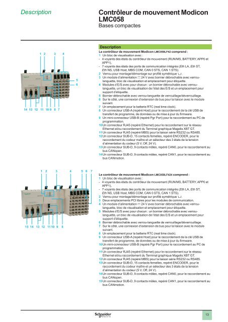
Le contrôleur <strong>de</strong> <strong>mouvement</strong> <strong>Modicon</strong> <strong>LMC058</strong>LF42 comprend :<br />
1 Un bloc <strong>de</strong> visualisation avec :<br />
- 4 voyants <strong>de</strong>s états du contrôleur <strong>de</strong> <strong>mouvement</strong> (RUN/MS, BATTERY, APP0 et<br />
APP1),<br />
- 7 voyants <strong>de</strong>s états <strong>de</strong>s ports <strong>de</strong> communication intégrés (Eth LA, Eth ST,<br />
Eth NS, USB Host, MBS COM, CAN 0 STS, CAN 1 STS).<br />
2 Verrou pour montage/démontage sur profilé symétrique 5.<br />
3 Un module d’alimentation c 24 V avec bornier débrochable avec verroulanguette,<br />
bloc <strong>de</strong> visualisation et emplacement pour étiquette.<br />
4 Modules d’E/S avec pour chacun : un bornier débrochable avec verroulanguette,<br />
un bloc <strong>de</strong> visualisation <strong>de</strong> l’état <strong>de</strong>s E/S et un emplacement pour<br />
support d’étiquette.<br />
5 Bornier débrochable avec verrou-languette <strong>de</strong> verrouillage/déverrouillage.<br />
6 Sur le côté, une connexion d’extension <strong>de</strong> bus pour la liaison avec le module<br />
suivant.<br />
7 Un emplacement pour la batterie RTC (real time clock).<br />
8 Un connecteur USB-A (repéré Host) pour le raccor<strong>de</strong>ment <strong>de</strong> la clé USB <strong>de</strong><br />
transfert <strong>de</strong> programme, <strong>de</strong> données ou <strong>de</strong> mise à jour du firmware.<br />
9 Un mini-connecteur USB-B (repéré Pgr Port) pour le raccor<strong>de</strong>ment au PC <strong>de</strong><br />
programmation.<br />
10 Un connecteur RJ45 (repéré Ethernet) pour le raccor<strong>de</strong>ment sur le réseau<br />
Ethernet et/ou raccor<strong>de</strong>ment du Terminal graphique Magelis XBT GT.<br />
11 Un connecteur RJ45 (repéré MBS) pour la liaison série RS232 ou RS485.<br />
12 Un connecteur SUB-D, 15 contacts femelles, repéré ENCODER, pour le<br />
raccor<strong>de</strong>ment du co<strong>de</strong>ur maître et un sélecteur <strong>de</strong>s 3 états <strong>de</strong> la tension<br />
d’alimentation du co<strong>de</strong>ur (5 V, Off, 24 V).<br />
13 Un connecteur SUB-D, 9 contacts mâles, repéré CAN0, pour le raccor<strong>de</strong>ment au<br />
bus CANopen.<br />
14 Un connecteur SUB-D, 9 contacts mâles, repéré CAN1, pour le raccor<strong>de</strong>ment au<br />
bus CANmotion.<br />
1<br />
2<br />
3<br />
4<br />
5<br />
15<br />
14<br />
13<br />
1 2<br />
12<br />
11 10<br />
3 4 5 6 7<br />
9<br />
8<br />
Le contrôleur <strong>de</strong> <strong>mouvement</strong> <strong>Modicon</strong> <strong>LMC058</strong>LF424 comprend :<br />
1 Un bloc <strong>de</strong> visualisation avec :<br />
- 4 voyants <strong>de</strong>s états du contrôleur <strong>de</strong> <strong>mouvement</strong> (RUN/MS, BATTERY, APP0 et<br />
APP1),<br />
- 7 voyants <strong>de</strong>s états <strong>de</strong>s ports <strong>de</strong> communication intégrés (Eth LA, Eth ST,<br />
Eth NS, USB Host, MBS COM, CAN 0 STS, CAN 1 STS).<br />
2 Verrou pour montage/démontage sur profilé symétrique 5.<br />
3 Deux emplacements PCI libres pour les modules <strong>de</strong> communication.<br />
4 Un module d’alimentation c 24 V avec bornier débrochable avec verroulanguette,<br />
bloc <strong>de</strong> visualisation et emplacement pour étiquette.<br />
5 Modules d’E/S avec pour chacun : un bornier débrochable avec verroulanguette,<br />
un bloc <strong>de</strong> visualisation <strong>de</strong> l’état <strong>de</strong>s E/S et un emplacement pour<br />
support d’étiquette.<br />
6 Bornier débrochable avec verrou-languette <strong>de</strong> verrouillage/déverrouillage.<br />
7 Sur le côté, une connexion d’extension <strong>de</strong> bus pour la liaison avec le module<br />
suivant.<br />
8 Un emplacement pour la batterie RTC (real time clock).<br />
9 Un connecteur USB-A (repéré Host) pour le raccor<strong>de</strong>ment <strong>de</strong> la clé USB <strong>de</strong><br />
transfert <strong>de</strong> programme, <strong>de</strong> données ou <strong>de</strong> mise à jour du firmware.<br />
10 Un mini-connecteur USB-B (repéré Pgr Port) pour le raccor<strong>de</strong>ment au PC <strong>de</strong><br />
programmation.<br />
11 Un connecteur RJ45 (repéré Ethernet) pour le raccor<strong>de</strong>ment sur le réseau<br />
Ethernet et/ou raccor<strong>de</strong>ment du Terminal graphique Magelis XBT GT.<br />
12 Un connecteur RJ45 (repéré MBS) pour la liaison série RS232 ou RS485.<br />
13 Un connecteur SUB-D, 15 contacts femelles, repéré ENCODER, pour le<br />
raccor<strong>de</strong>ment du co<strong>de</strong>ur maître et un sélecteur <strong>de</strong>s 3 états <strong>de</strong> la tension<br />
d’alimentation du co<strong>de</strong>ur (5 V, Off, 24 V).<br />
14 Un connecteur SUB-D, 9 contacts mâles, repéré CAN0, pour le raccor<strong>de</strong>ment au<br />
bus CANopen.<br />
15 Un connecteur SUB-D, 9 contacts mâles, repéré CAN1, pour le raccor<strong>de</strong>ment au<br />
bus CANmotion.<br />
6<br />
7<br />
8<br />
9<br />
10<br />
13