Istruzioni di montaggioFV - Vismaravetro Srl
Istruzioni di montaggioFV - Vismaravetro Srl
Istruzioni di montaggioFV - Vismaravetro Srl

Create successful ePaper yourself
Turn your PDF publications into a flip-book with our unique Google optimized e-Paper software.
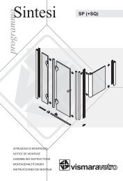
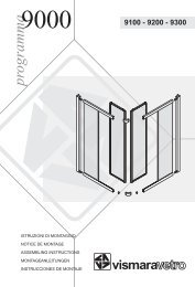
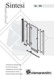
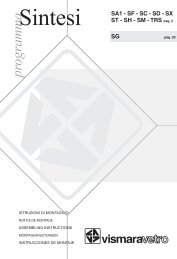
programma<br />
Alibi<br />
FV pag. 2<br />
ISTRUZIONI DI MONTAGGIO<br />
NOTICE DE MONTAGE<br />
ASSEMBLING INSTRUCTIONS<br />
MONTAGEANLEITUNGEN<br />
INSTRUCCIONES DE MONTAJE<br />
vismara
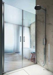
Alibi FV<br />
2
MAB07<br />
MAL05<br />
MAB02<br />
MAB07<br />
MAL04<br />
MAB20<br />
MAB09<br />
MAB21<br />
MAB08<br />
MAB03<br />
MAL05<br />
MAL04<br />
MAB07<br />
MAB01<br />
MAB10<br />
3
Alibi FV<br />
4
MAB04<br />
MAL05<br />
MAB02<br />
MAL04<br />
MAB20<br />
MAB21<br />
MAB08<br />
MAB03<br />
MAL05<br />
MAL04<br />
MAB01<br />
MAB10<br />
5
Alibi FV<br />
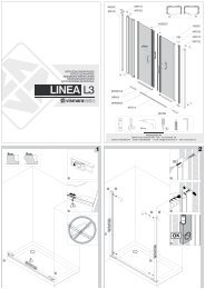
I<br />
Verificare che il muretto o bordo vasca sia in bolla.<br />
Posizionare i montanti sul muretto o bordo vasca e verificare il profilo (P) sia allineato a filo interno del muretto<br />
o filo esterno del bordo vasca. La parte alta è identificata dal giunto terminale con 3 viti (V1 e V2).<br />
Segnare sulla parete la posizione dei due fori e procedere alla foratura con punta Ø6 mm. Inserire il tassello<br />
nel foro. Collocare la borchia zigrinata (BZ) nel foro del montante e procedere al fissaggio. Agendo sulla borchia<br />
(BZ) è possibile correggere la posizione del montante. Infilare i coprivite (C).<br />
Nel caso le pareti siano costituite con materiali <strong>di</strong> scarsa tenuta (cartongesso, porte a<br />
scrigno,...), non utilizzare i tasselli forniti, ma procurare adeguati sistemi <strong>di</strong> fissaggio.<br />
F<br />
Contrôler que le muret ou le bord de la baignoire est de niveau. Positionner les montants sur le muret ou le<br />
bord de la baignoire et vérifier que le profilé (P) est aligné au bord interne du muret ou bord externe de la<br />
baignoire. La partie haute est identifiable grâce aux 3 vis (V1 et V2). Tracer sur la cloison la position des 2<br />
trous de fixation du profilé. Procéder au percement avec un foret de 6 mm. Mettre les chevilles en place. Mettre<br />
les pièces spéciales (BZ) dans les 2 trous du profilé. Procéder au vissage dans la cloison, corriger éventuellement<br />
l'aplomb en agissant sur les pièces crénelées (BZ). Mettre les caches vis (C).<br />
Avant d'effectuer la fixation des montants, il est très important de vérifier la nature des cloisons<br />
sur lesquelles ceux-ci seront fixés. Il faut obligatoirement utiliser des chevilles appropriées<br />
à la nature des cloisons.<br />
GB<br />
Check that the small wall or the bath tub edge is level.<br />
Position the profiles on the small wall or bath tub edge and check that the profile (P) is aligned<br />
along the inside border of the small wall or the outside bath tub edge. The upper part is identified by 3 screws<br />
(V1 and V2).<br />
Mark the wall for drilling through the door wall post. Drill the hole with a 6 mm drill and insert fixing in the<br />
hole and fix post by screwing through knurled block (BZ). Adjust by moving knurled block (BZ) and tighten<br />
when post is exactly vertical. Cover with small cap (C).<br />
In case of low resistance walls (plaster walls, casket doors, ..) don't use the supplied screws<br />
but provide adequate fixing solution.<br />
D<br />
Prüfen Sie: <strong>di</strong>e Mauer oder der Badewannenrand muss exakt waagerecht montiert sein. Die Wandprofile an der<br />
Mauer oder auf dem Badewannenrand positionieren und prüfen: das Profil (P) muss zum Innenrand der Mauer<br />
oder zum Aussenrand der Badewanne ausgerichtet sein. Der oberen Profilteil ist beim Aufsatz mit 3 Schrauben<br />
(V1 und V2) gekennzeichnet. Die Wand nach der Stellung der zwei Löcher mit Bohrer 6 mm durchbohren. Das<br />
einsatz Stück ins Loch stecken. Das gerändelte Element (BZ) ins Loch des Türpfostens stecken. Den Türpfosten<br />
an <strong>di</strong>e Wand mit Hilfe der gerändelten Elemente (BZ) anschrauben. Den Schraubendecker hinaufsetzen (C).<br />
Falls <strong>di</strong>e Wand eine Fertigteilwand ist oder aus einem Material mit schwacher Resistenz<br />
besteht, bitte nicht <strong>di</strong>e beigelegten Dübel verwenden sondern das dazu passende<br />
Befestigungsmaterial besorgen bzw. verwenden.<br />
SP<br />
Comprobar que el muro o el borde de la bañera esté nivelado. Colocar el montante sobre el muro o borde de<br />
bañera y comprobar que el perfil (P) esté alineado con el canto interno del muro o canto externo del borde<br />
de la bañera. La parte superior del montante se identifica por llevar un terminal con tres tornillos (V1 y V2).<br />
Marcar en la pared la posición de los dos agujeros y proceder al agujereado con broca de 6 mm. Insertar los<br />
tacos en los agujeros, colocar la pieza con coliso (BZ) en al agujero del montante y proceder a su fijación.<br />
Girando la pieza (BZ) es posible coregir la posición del montante. Colocar el embellecedor (C).<br />
En caso de que las paredes sean de material de poca resistencia (pladur, pared de puerta<br />
corredera, etc) no usar los tacos suministrados, deben procurarse sistemas de fijación<br />
adecuados al caso.<br />
6
V2<br />
V1<br />
BZ<br />
C<br />
Fig. 1/a<br />
Fig. 1<br />
7
Alibi FV<br />
I<br />
REGOLAZIONE DELLA PARETE<br />
FISSA<br />
Dopo aver allentato le tre viti superiori<br />
(V1 e V2), sollevare leggermente la<br />
parete fissa per <strong>di</strong>simpegnarla<br />
dall'appoggio inferiore dentato;<br />
estenderla quanto richiesto e<br />
rilasciarla.<br />
A fine operazione, serrare le tre viti<br />
superiori (V1 e V2).<br />
F<br />
REGLAGE DE LA PARTIE FIXE<br />
Après avoir desserré les trois vis<br />
supérieures ( V1 et V2 ), soulever<br />
légèrement la partie fixe pour dégager<br />
la pièce de réglage crantée inférieure,<br />
étirer jusqu'a la position souhaitée et<br />
reposer la partie fixe.<br />
A la fin de cette opération serrer les<br />
trois vis supérieures ( V1 et V2 ).<br />
GB<br />
SIDE PANEL REGULATION<br />
After loosening the three upper screws<br />
(V1 and V2), lightly pick up the side<br />
panel to release it from the lower<br />
notched part. Extend it to the necessary<br />
position and release it.<br />
After this operation tighten the three<br />
upper screws (V1 and V2).<br />
Fig. 2<br />
D<br />
FIXGLASWAND REGULIERUNG<br />
Nach den man <strong>di</strong>e 3 oberen Schrauben (V1 und V2 ) gelockert hat, das Fixteil leicht anheben, dann herausziehen<br />
auf <strong>di</strong>e gewünschte Position, sowie wieder senken.<br />
Zuletzt <strong>di</strong>e 3 Schrauben (V1 und V2) festziehen.<br />
SP<br />
REGULACIÓN DE LA PARED FIJA<br />
Después de haber aflojado los tres tornillos superiores (V1 y V2), elevar ligeramente la pared fija para liberarla<br />
del apoyo inferior dentado; extenderla hasta la posición deseada y bajarla de nuevo.<br />
Al finalizar la operación, apretar los tres tornillos superiores (V1 y V2).<br />
8
V1<br />
V2<br />
Fig. 2/a<br />
V1<br />
F<br />
V2<br />
vetro<br />
verre<br />
glass<br />
Glas<br />
vidrio<br />
vetro<br />
verre<br />
glass<br />
Glas<br />
vidrio<br />
9
Alibi FV<br />
I<br />
Allineare il profilo (U) al profilo (P) e centrarlo sulla base B del profilo SMF .<br />
Procedere al fissaggio dei due profili (U + P) tramite le apposite viti e fissare il profilo ad "U" al muro nella<br />
parete inferiore con l'apposito tassello Ø 6 mm.<br />
F<br />
Aligner le profilé (U) au profilé (P) et le centrer sur la base B du profilé SMF.<br />
Procéder à la fixation des deux profilés (U +P) avec les vis fournies et fixer le profilé en " U " au muret dans<br />
la partie inférieure avec les chevilles Ø 6 mm.<br />
GB<br />
Align the profile (U) to the profile (P) and center on the base B of the SMF profile.<br />
Proceed with the fixing of the 2 profiles (U+P) with the supplied screws and fix the profile "U" to the wall in<br />
the lower part with the supplied dowel Ø 6 mm.<br />
D<br />
Das Profil (U) an dem Profil (P) ausrichten und auf der Basis B vom SMF Profil zentrieren.<br />
Die zwei Profile (U + P) durch <strong>di</strong>e Schrauben befestigen und das Profil "U" unten mit dem Ø 6 mm Dübel an<br />
der Mauer befestigen.<br />
SP<br />
Alinear el perfil (U) al perfil(P) y centrarlo sobre la base B del perfil SMF.<br />
Proceder a la fijación de los dos perfiles (U+P) me<strong>di</strong>ante sus correspon<strong>di</strong>entes tornillos y fijar el perfil en "U"<br />
al muro en la parte inferior con su correspon<strong>di</strong>ente taco de 6 mm.<br />
10
P<br />
U<br />
B<br />
Fig. 3/a<br />
Fig. 3/b<br />
Fig. 3<br />
11
Alibi FV<br />
I<br />
FV più ANTA<br />
Prima <strong>di</strong> procedere al montaggio dell'anta, verificare che il montante (M+C) sia centrato sulla guida della base<br />
B del profilo SMF.<br />
Posizionare il montante dell'anta a piombo, infilarlo nel profilo ad "U" e fissarlo con le viti.<br />
Montare l'anta e procedere al montaggio delle parti restanti della cabina doccia seguendo le relative istruzioni.N.B.<br />
Verificare che il tappo con le TRE viti sia rivolto verso l'alto.<br />
F<br />
Avant de procéder avec le montage de la porte, vérifier que le montant (M+C) est centré sur la guide de la base<br />
B du profilé SMF.<br />
Positionner le montant de la porte en contrôlant la verticalité , l'introduire dans le profilé en " U " et le fixer<br />
avec les vis.<br />
Installer la porte et procéder au montage des autres parties de la cabine de douche selon les instructions.<br />
N.B. Vérifier que le bouchon avec les TROIS vis soit tourné en haut.<br />
GB<br />
FV with ANTA<br />
Before procee<strong>di</strong>ng with the installation of the door, check that the profile (M+C) is centred on the guide of base<br />
B of SMF profile.<br />
Position the profile of the door in a perfect vertical position, insert it into the "U" profile and fix it with the<br />
screws.<br />
Assemble the door and proceed with the assembling of the remaining parts of the shower enclosure accor<strong>di</strong>ng<br />
to the instructions.<br />
N.B. Check that the cap with the 3 screws is upwards.<br />
D<br />
FV più ANTA<br />
Bevor <strong>di</strong>e Türe zu montieren, prüfen Sie, ob das Wandprofil (M+C) auf der Basis B vom SMF Profil zentriert ist.<br />
Das Türwandprofil positionieren und prüfen , ob es gerade ausgerichtet ist. Im Profil "U" das Türprofil<br />
einführen und mit den Schrauben befestigen.<br />
Die Türe und <strong>di</strong>e andere Teile der Duschabtrennung nach der entsprechenden Montageanleitungen montieren.<br />
N.B.: Prüfen Sie, ob der Stopfen mit DREI Schrauben nach oben gerichtet ist.<br />
SP<br />
FV más ANTA<br />
Antes de proceder al montaje de la puerta, verificar que el montante (M+C) esté centrado sobre la guía de la<br />
base B del perfil SMF.<br />
Colocar el montante de la puerta a nivel, enfilarlo en el perfil en "U" y fijarlo con los tornillos.<br />
Montar la puerta y proceder al montaje de las partes restantes de la cabina de ducha siguiendo las instrucciones.<br />
N.B.: Verificar que el terminal con los TRES tornillos esté situado en la parte superior.<br />
12
U<br />
M+C<br />
Fig. 4/a<br />
Fig. 4A<br />
13
Alibi FV<br />
I<br />
FV più FISSO<br />
Posizionare il montante con il vetro a piombo, infilarlo nel profilo a "U" e fissarlo con le viti.<br />
Procedere al montaggio delle parti restanti della cabina doccia seguendo le relative istruzioni.<br />
N.B. Verificare che il tappo con le TRE viti sia rivolto verso l'alto.<br />
F<br />
FV avec FISSO<br />
Positionner le montant avec le verre à plomb, l'introduire dans le profilé "U" et le fixer avec les vis.<br />
Procéder au montage des autres parties de la cabine de douche selon les instructions.<br />
N.B. Vérifier que le bouchon avec les TROIS vis soit tourné en haut.<br />
GB<br />
FV with FISSO<br />
Position the profile with the glass in a perfect vertical position, insert into the "U" profile and fix it with the<br />
screws.<br />
Proceed with the assembly of the remaining parts of the shower enclosures accor<strong>di</strong>ng to the instructions.<br />
N.B. Check that the cap with the 3 screws is upwards.<br />
D<br />
FV più FISSO<br />
Das Wandprofil mit Glas gerade waagerecht positionieren. Im Profil "U" das Wandprofil einführen und mit den<br />
Schrauben befestigen.<br />
Die andere Teile der Duschabtrennung nach der entsprechenden Montageanleitungen montieren.<br />
N.B.: Prüfen Sie, ob der Stopfen mit DREI Schrauben nach oben gerichtet ist.<br />
SP<br />
FV más FISSO<br />
Colocar el montante con el cristal a nivel, enfilarlo en el perfil en "U" y fijarlo con los tornillos.<br />
Proceder al montaje de las partes restantes de la cabina de ducha siguiendo las instrucciones.<br />
N.B.: Verificar que el terminal con los TRES tornillos esté situado en la parte superior.<br />
14
U<br />
M+C<br />
Fig. 4/b<br />
Fig. 4B<br />
15
24 h<br />
<strong>Vismaravetro</strong> <strong>Srl</strong><br />
20050 Verano Brianza (MI) - Italy<br />
Via Furlanelli, 29<br />
telefono 0362/992244<br />
telefax 0362/992255<br />
e-mail: info@vismaravetro.it<br />
www.vismaravetro.it<br />
vismara