Fluke - delta technique instrumentation
Fluke - delta technique instrumentation
Fluke - delta technique instrumentation

Create successful ePaper yourself
Turn your PDF publications into a flip-book with our unique Google optimized e-Paper software.
It frequently happens that service are automatically detected and<br />
engineers have to spend a lot of adjusted, followed by displaying<br />
the signal in the correct ratio<br />
time adjusting their measuring<br />
device such as a portable oscilloscope<br />
for an optimal setting. and vertical axis. At least 1.5<br />
with respect to the horizontal<br />
Valuable time is spent completing to 4 periods of the signal are<br />
this set up, and ideally, this could measured before the pattern is<br />
be done automatically.<br />
shown.<br />
With the introduction of the Connect and View provides<br />
new ScopeMeter 190 Series II, a stable, reliable and repeatable<br />
display of virtually any<br />
<strong>Fluke</strong> has revamped its unique<br />
feature, Connect and View. signal, including motor drive and<br />
Scope users know how difficult<br />
triggering can be. Wrong ing a button. Signal changes are<br />
control signals, without touch-<br />
settings show unstable and instantly recognized and settings<br />
sometimes wrong results. <strong>Fluke</strong>’s adjusted for, once again, a stable<br />
unique Connect and View display. This is all done automatically,<br />
but manual overruling<br />
recognizes signal patterns, and<br />
automatically sets up correct is still possible. If manual overruling<br />
is needed, the ScopeMeter<br />
triggering, attenuator and time<br />
base settings. Switching on the 190 Series will switch from automatic<br />
to 1/2 automatic, which is<br />
ScopeMeter portable oscilloscope<br />
to display correct signal patterns visible on the display.<br />
only takes a couple of seconds, Figure 1 gives an example of<br />
and this is exactly what an the different types of waveforms<br />
operator wants.<br />
which can de detected by<br />
Settings regarding<br />
Connect & View. If required the<br />
amplitude,<br />
criteria for best settings can be AC/DC coupling<br />
timebase,<br />
optimized by switching on one or Glitch detect<br />
triggering,<br />
all of the following options: Figure 2 shows the different<br />
etc.<br />
Automatic trigger<br />
settings.<br />
Figure 1.<br />
From the <strong>Fluke</strong> Digital Library @ www.fluke.com/library<br />
75 Ω<br />
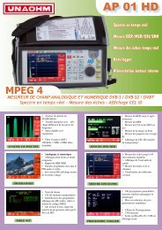
ScopeMeter 190 série II<br />
® 190 Series II<br />
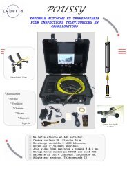
Testing telecommunication<br />
equipment using Pass/Fail<br />
mask testing with a <strong>Fluke</strong><br />
ScopeMeter<br />
G.703 is a standard origina<br />
ly introduced for voice and<br />
data transmission over digital<br />
networks. It an ITU recommendation<br />
(formerly CCITT)<br />
that’s associated with the PCM<br />
standard. Analog-voice to digitaldata<br />
conversion according to<br />
PCM requires a bandwidth of<br />
64 kb/s (±100 ppm), resulting in<br />
the basic unit for G.703. Through<br />
multiplexing this results in a T1<br />
of 1.544 Mb/s and E1 of<br />
2.048 Mb/s.<br />
Th electrical characteristics<br />
of the network interfaces are<br />
described in recommendation<br />
G.703. The signal limits for a<br />
2.048 Mb/ signal are shown in<br />
Figure 1.<br />
The G.703 standard<br />
Multiple-channel<br />
testing using two<br />
different masks<br />
Application Note<br />
Nowadays digital communication system such as Synchronous<br />
Digital Hierarchy (SDH) in Europe and the Synchronous Optical<br />
Network (SONET) in North America require standard test methods.<br />
The electrical signals are tested agains the standard ITU pulse<br />
masks. The <strong>Fluke</strong> ScopeMeter 190 Series I portable osci loscope<br />
o fers a standard pass/fail function that can be used to perform<br />
these tests. The instrument is capable of storing up to 100 “fails”<br />
for further analysis.<br />
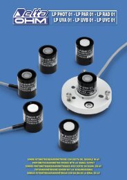
Demystifying<br />
drive anomalies<br />
using the <strong>Fluke</strong> 190 Series II 2-Channel<br />
ScopeMeter ® portable osci loscope<br />
Testing<br />
Functions<br />
Case<br />
Study<br />
Measuring tools: 190 Series I<br />
2-Channel ScopeMeter<br />
Operator: Chris Vogel, HVAC<br />
Technician for Siemens Building<br />
Technologies<br />
Figure 1. G703 - E1 template<br />
A balun is used between the<br />
patch panel and a coaxial<br />
transmission line to match the<br />
impedance of the 120 Ω symmetrical<br />
line to a 75 Ω coaxial<br />
line. The input and output of the<br />
balun each has it specific mask.<br />
The ScopeMeter 190 Series I<br />
portable osci loscopes can simultaneously<br />
perform a pass/fail test<br />
at the input and output of the<br />
balun with di ferent masks.<br />
The floating and isolated With <strong>Fluke</strong>View we can export<br />
inputs of the <strong>Fluke</strong> ScopeMeter a waveform into a spreadsheet<br />
190 Series I test tools make and a custom template can be<br />
these measurements possible<br />
without the risk of making using Excel.<br />
created by editing a waveform<br />
unwanted groundings. Moreover, A reference template for<br />
the high impedance probes allow pass/fail testing can be created<br />
by saving waveforms from<br />
for direct measurements without<br />
loading the line and without the <strong>Fluke</strong>View in .csv format and<br />
need for an external di ferential editing the waveform using, for<br />
® Test Tool<br />
probe.<br />
Editing the pass/fail<br />
templates<br />
Measurements: Current and voltage<br />
waveform analysis, power factor<br />
Telephone<br />
Exchange<br />
2 Mb/s<br />
120 Ω<br />
ISDN 30<br />
Figure 2. ISDN30 network<br />
Application Note<br />
Connect the ScopeMeter<br />
test tool and view the<br />
result: the start of every<br />
measurement<br />
Seeing is believing? More aptly, seeing is<br />
understanding.<br />
If anyone can wring every last ounce of functionality out<br />
of a piece of electronic test equipment, it’s Chris Vogel.<br />
At Siemens Building Technologies, Vogel has his work cut<br />
out for him keeping HVAC systems running for the company’s<br />
large commercial customers in Florida’s tropical<br />
weather, which is marked by seemingly nonstop 90 °F<br />
temperatures and 95 % humidity levels. And that’s just<br />
one of the challenges faced by technicians at Siemens<br />
Building Technologies, which plays a more sweeping role<br />
in its customers’ success: ensuring energy e ficiency,<br />
comfort, protection against unauthorized access, and<br />
fire safet year-round for every building or office tower<br />
entrusted to it by customers.<br />
Patch<br />
Panel<br />
Balun SDH<br />
Distr.<br />
From the <strong>Fluke</strong> Digital Library @ www.fluke.com/library<br />
2 Mb/s<br />
120 Ω<br />
Storing a slice of time<br />
Vogel, an HVAC technician,<br />
becomes energized when discussing<br />
the return on investment<br />
It’s important, says Vogel,<br />
in his handheld<br />
that the technician be able to<br />
ScopeMeter®<br />
Test Tool. “Out at one large site,<br />
characterize VFD problems by<br />
where we monitor and troubleshoot<br />
variable frequency drives<br />
capturing a waveform from the<br />
o fending drive. His premise: A<br />
(VFDs), component-level repair<br />
signal is much more telling when<br />
can often mean the di ference<br />
presented in a waveform view<br />
between a $20 repair part and<br />
than in a single, static voltage<br />
reading. The signal has a<br />
a $100,000 repair bi l. I know<br />
firsthand, because we recently<br />
shape and value that may look<br />
documented that very scenario.”<br />
right at a glance, but could just<br />
On large VFDs, Vogel uses his<br />
as easily have a distortion or<br />
ScopeMeter portable osci loscope<br />
rough “edge,” or a momentary<br />
to uncover capacitance problems,<br />
spike almost too short to be<br />
transistor firing mishaps, and<br />
seen. Either problem, or a host<br />
even bleed-throughs on a gate.<br />
of other signal anomalies, would<br />
“Of course, a transistor is basica<br />
ly a lightning-fast switch,”<br />
be indistinguishable with just a<br />
numeric reading of the signal.<br />
he says. “It switches back and<br />
“The scope allows me to<br />
forth between open and closed,<br />
record information, and from a<br />
and it can sometimes start to<br />
number of sources—sine waves<br />
break down. When that happens,<br />
on the inputs and outputs of<br />
motors wi l start doing weird<br />
VFDs, cu rent and voltage—and,<br />
things. For example, at load<br />
for that ma ter, make comparisons<br />
of current and voltage so<br />
stage we’ l actually see<br />
the motor banging back and<br />
that I can derive a power factor<br />
forth as if it is not sure which<br />
for the circuit.”<br />
way to turn.”<br />
From the <strong>Fluke</strong> Digital Library @ www.fluke.com/library<br />
2 Mb/s<br />
Application Note<br />
Un grand nombre de notes d’application est disponible.<br />
Pour plus d’informations, rendez-vous<br />
sur le site Web de <strong>Fluke</strong>.<br />
Accessoires inclus<br />
Les appareils <strong>Fluke</strong> 190 série II à quatre voies sont livrés<br />
avec un jeu de quatre sondes, une sangle de suspension,<br />
une dragonne, un câble USB avec mini-connecteur B,<br />
une batterie Li-ion BP291 à double capacité, un chargeur<br />
de batteries / adaptateur secteur BC190, un logiciel de<br />
démonstration <strong>Fluke</strong>View ® et un manuel de l’utilisateur<br />
sur CD-ROM.<br />
Les versions /S sont par ailleurs accompagnées des<br />
accessoires supplémentaires suivants : malette de<br />
transport rigide C290 et logiciel <strong>Fluke</strong>View ® ScopeMeter<br />
(version intégrale).<br />
Les modèles à deux voies sont livrés avec deux sondes, un<br />
jeu de cordons de mesure TL175, et une batterie simple<br />
capacité BP290.<br />
Le modèle 190-502 comprend également deux connecteurs<br />
de terminaison de traversée coaxiaux TRM50.<br />
Le pack SCC290 comprend : une malette de transport<br />
rigide C290 et le logiciel <strong>Fluke</strong>View ® pour Windows ®<br />
(version intégrale).<br />
Informations pour la commande<br />
<strong>Fluke</strong>-190-502/S ScopeMeter couleur (500 MHz, 2 voies),<br />
avec le pack SCC290<br />
<strong>Fluke</strong>-190-204/S ScopeMeter couleur (200 MHz, 4 voies),<br />
avec le pack SCC290<br />
<strong>Fluke</strong>-190-204 ScopeMeter couleur (200 MHz, 4 voies)<br />
<strong>Fluke</strong>-190-202/S ScopeMeter couleur (200 MHz, 2 voies),<br />
avec le pack SCC290<br />
<strong>Fluke</strong>-190-202 ScopeMeter couleur (200 MHz, 2 voies)<br />
<strong>Fluke</strong>-190-104/S ScopeMeter couleur (100 MHz, 4 voies),<br />
avec le pack SCC290<br />
<strong>Fluke</strong>-190-104 ScopeMeter couleur (100 MHz, 4 voies)<br />
<strong>Fluke</strong>-190-062/S ScopeMeter couleur (60 MHz, 2 voies),<br />
avec le pack SCC290<br />
<strong>Fluke</strong>-190-062 ScopeMeter couleur (60 MHz, 2 voies)<br />
AS400<br />
Jeu d’accessoires<br />
supplémentaires pour sondes de la<br />
série VPS400<br />
BP291<br />
BP290<br />
C195<br />
C290<br />
EBC290<br />
HH290<br />
RS400<br />
RS500<br />
SCC290<br />
SW90W<br />
TRM50<br />
VPS410-x<br />
VPS420-R<br />
VPS510-x<br />
Pack de batterie Li-ion double capacité<br />
(4 800 mAh) pour instruments <strong>Fluke</strong><br />
190C série II<br />
Pack de batterie Li-ion double capacité<br />
(2 400 mAh) pour instruments <strong>Fluke</strong><br />
190C série II<br />
Sacoche de transport souple rembourrée<br />
pour ScopeMeter et accessoires<br />
Malette de transport protectrice pour<br />
les modèles <strong>Fluke</strong> 190 série II<br />
Chargeur de batterie externe<br />
permettant de recharger la batterie<br />
BP290 ou BC291 lorsqu’elle sortie de<br />
l’instrument<br />
Crochet de suspension<br />
Jeu d’accessoires de rechange pour<br />
sondes de la série VPS400<br />
Jeu d’accessoires de rechange pour<br />
sondes de la série VPS510<br />
Pack comprenant le logiciel et la malette<br />
de transport pour les instruments <strong>Fluke</strong><br />
190 série II. Inclus : SW90W et C290.<br />
Logiciel <strong>Fluke</strong>View ® ScopeMeter pour<br />
Windows ® (version intégrale)<br />
connecteur de terminaison de traversée<br />
coaxial 50 Ω<br />
Jeu de sondes, 10:1, 1 000 V CAT III / 600 V<br />
CAT IV (couleurs : bleu, vert, rouge, gris)<br />
Jeu de sondes bicolores (rouge / noir),<br />
100:1, 150 MHz, 1 000 V CAT III / 600 V<br />
CAT IV, tension de travail (tension entre<br />
la pointe de sonde et le conducteur de<br />
référence) : 2 000 V CAT III / 1 200 V<br />
CAT IV. CAT IV.<br />
Jeu de sondes à large bande passante,<br />
500 MHz, 10:1, 600 V CAT III<br />
Déclenchement automatique Connect-and-<br />
View pour un affichage stable, instantané<br />
Si vous avez utilisé d’autres oscilloscopes, vous<br />
savez que le déclenchement peut être délicat. Si les<br />
paramètres sont incorrects, les résultats peuvent<br />
être instables ou incorrects. La fonctionnalité<br />
Connect-and-View configure automatiquement<br />
le déclenchement en reconnaissant le profil des<br />
signaux. Sans toucher à un seul bouton, vous<br />
obtenez un affichage stable, fiable et reproductible<br />
de pratiquement tout signal, y compris des signaux<br />
de moteurs et de contrôle. Cette fonctionnalité est<br />
particulièrement rapide et pratique lors de la mesure<br />
de nombreux points de test en succession rapide.<br />
Modèles <strong>Fluke</strong> 190 série II à deux entrées isolées et<br />
multimètre numérique dédié. Passez facilement de<br />
l’analyse de forme d’ondes à la prise de mesures<br />
précises grâce au multimètre numérique intégré<br />
de 5 000 points. Nombreuses fonctions de mesure,<br />
dont Vdc, Vac, Vac+dc, résistance, continuité, mesure<br />
de diode. Mesurez le courant et la température en<br />
utilisant le shunt, la sonde ou l’adaptateur adéquats<br />
avec une gamme étendue de facteurs d’échelle.<br />
Les utilisateurs d’oscilloscope savent à quel point il est déroutant d’apercevoir<br />
brièvement une anomalie ponctuelle puis de ne plus la retrouver. Cela ne risque pas<br />
de vous arriver avec les oscilloscopes <strong>Fluke</strong> 190 série II.<br />
“Vous pouvez désormais retrouver vos mesures<br />
passées d’une simple pression sur un bouton.”<br />
En fonctionnement normal, l’instrument mémorise<br />
continuellement les 100 derniers écrans. Vous pouvez<br />
à tout moment figer ces 100 écrans et les faire<br />
défiler un à un ou bien les afficher en continu. Les<br />
curseurs et la fonction zoom permettent une analyse<br />
approfondie.<br />
Vous pouvez même utiliser les possibilités de déclenchement évoluées pour saisir<br />
jusqu’à 100 événements particuliers. Deux ensembles de 100 écrans avec des<br />
horodatages individuels peuvent être enregistrés et consultés par la suite ou bien<br />
téléchargés sur un PC.<br />
Affichez instantanément le comportement<br />
dynamique des signaux<br />
SW90W<br />
SCC290<br />
VPS420-R<br />
La fonction Connect-and-View<br />
détecte même les signaux de<br />
variateurs de vitesse les plus<br />
complexes.<br />
Multimètre numérique intégré (modèle à double entrée)<br />
Multimètre intégré : des mesures<br />
précises en toute simplicité<br />
Capture automatique et restitution de 100<br />
écrans<br />
Le mode de Persistance numérique vous aide à trouver des anomalies et à analyser<br />
des signaux dynamiques complexes. L’appareil indique la distribution de l’amplitude<br />
des formes d’onde au cours du temps à l’aide de niveaux d’intensité multiples et<br />
grâce à un temps d’atténuation sélectionnable par l’utilisateur : c’est comme si vous<br />
regardiez l’afficheur d’un oscilloscope analogique en temps réel ! Une haute fréquence<br />
de mise à jour de l’affichage révèle instantanément les variations du signal, ce qui est<br />
utile par exemple pour les réglages d’un système en cours de test.<br />
Accessoires recommandés<br />
EBC290<br />
AS400<br />
83