6 Positions- und Geschwindigkeitsregler Position ... - Bosch Rexroth
6 Positions- und Geschwindigkeitsregler Position ... - Bosch Rexroth
6 Positions- und Geschwindigkeitsregler Position ... - Bosch Rexroth

Create successful ePaper yourself
Turn your PDF publications into a flip-book with our unique Google optimized e-Paper software.
160 Industrial Hydraulics<br />
<strong><strong>Position</strong>s</strong>- <strong>und</strong> <strong>Geschwindigkeitsregler</strong><br />
<strong>Position</strong> and velocity controller<br />
Régulateur de position et de vitesse<br />
1<br />
6<br />
2 3<br />
4<br />
5 6
Industrial Hydraulics 161<br />
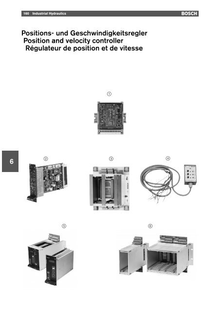
Bestellübersicht<br />
Ordering range<br />
Gamme de commande<br />
Typ Benennung Seite<br />
Type Description Page<br />
Type Désignation UBY ... Page «<br />
1 AVPC-V Lage- <strong>und</strong> <strong>Geschwindigkeitsregler</strong> 013/117 162 0 811 405 139<br />
AVPC-mA <strong>Position</strong> and velocity controller 0 811 405 140<br />
Régulateur de position et de vitesse<br />
2 APC3-SVZ <strong><strong>Position</strong>s</strong>reglerkarte 013/105 169 B 830 303 574<br />
<strong>Position</strong> controller card<br />
Carte de régulation de position<br />
3 CH 05 Gehäuse für <strong><strong>Position</strong>s</strong>regelung zu 2 013/93 176 1 817 218 003<br />
Chassis for position controlling to 2<br />
Boîtier pour régulation de position avec 2<br />
6<br />
4 Teststeuergerät zu 2 013/93 180 B 830 303 505<br />
Test controller to 2<br />
Appareil de commande de test avec 2<br />
5 DPCD- Digitaler <strong>Position</strong>ierregler 013/119 181 0 811 405 129<br />
DPCA- Digital positioning controller 0 811 405 130<br />
DPCD-SYNC Régulateur de position numérique 0 811 405 131<br />
DPCA-SYNC 0 811 405 132<br />
6 CH 11-DPC Gehäuse für digitalen <strong>Position</strong>ierregler zu 5 013/118 196 1 817 218 012<br />
CH 22-DPC Chassis for digital positioning controller to 5 1 817 218 013<br />
CH 21-DPC Boîtier pour régulateur de position 1 817 218 010<br />
CH 41-DPC numérique 5 1 817 218 011
162 Industrial Hydraulics<br />
Lage- <strong>und</strong> <strong>Geschwindigkeitsregler</strong><br />
<strong>Position</strong> and velocity controller<br />
Régulateur de position et de vitesse<br />
Frontplatte<br />
Front plate<br />
Plaque frontale<br />
6<br />
Typ<br />
Verwendung<br />
Type<br />
Application<br />
Type Utilisation [kg] «<br />
AVPC-V Lage- oder Geschwindigkeitsregelung 0,25 0 811 405 139<br />
AVPC-mA <strong>Position</strong> or velocity control 0 811 405 140<br />
Régulation de position ou de vitesse
Industrial Hydraulics 163<br />
y<br />
Anwendungen<br />
yy<br />
Applications<br />
yyy<br />
Applications<br />
Mit Hilfe dieses Reglermoduls lassen<br />
sich in Verbindung mit <strong>Bosch</strong>-Servozylindern<br />
mit analogen Wegmeßsystemen<br />
(Potentiometer) einfache<br />
<strong><strong>Position</strong>s</strong>- oder Geschwindigkeitsregelungen<br />
darstellen. Da die gesamte<br />
Signalverarbeitung analog erfolgt <strong>und</strong><br />
das Modul lediglich mit den notwendigsten<br />
Merkmalen für den Aufbau<br />
einer Regelung ausgestattet ist, können<br />
die Kosten für den Antrieb niedrig<br />
gehalten werden. Als Besonderheit<br />
kommt hinzu, daß das Modul auf eine<br />
Geschwindigkeitsregelung intern<br />
(Frontplatte) umgeschaltet werden<br />
kann <strong>und</strong> jeweils eine Version für<br />
Spannungsschnittstelle <strong>und</strong> Stromschnittstelle<br />
bezogen auf die Soll- <strong>und</strong><br />
Istwerte angeboten wird.<br />
This controller module enables simple<br />
position or velocity control actions<br />
to be effected, in combination with<br />
<strong>Bosch</strong> servo cylinders with analog<br />
position measurement systems<br />
(potentiometers). Since the signals<br />
are processed in an analog manner<br />
and the module is only equipped with<br />
the most essential features required<br />
for performing a control action, we<br />
were able to keep the cost of the drive<br />
low. A further speciality of this module<br />
is that it can be switched over internally<br />
(front plate) to velocity control,<br />
and there is a version for voltage interface<br />
and a version for current interface,<br />
related to the setpoints and<br />
actual values.<br />
Ce module de régulation permet de<br />
réaliser des régulations de position<br />
ou de vitesse simples en combinaison<br />
avec des servo-vérins <strong>Bosch</strong> à<br />
systèmes de mesure de position<br />
analogiques (potentiomètres). Etant<br />
donné que l’ensemble du traitement<br />
des signaux s’effectue de façon analogique<br />
et que le module n’est doté que<br />
des caractéristiques indis-pensables<br />
pour la construction d’une régulation,<br />
il est possible de maintenir des coûts<br />
modérés pour l’entraînement. A cela<br />
viennent s’ajouter les particularités suivantes:<br />
la possibilité de commuter le<br />
module en interne (plaque frontale)<br />
sur une régulation de vitesse ainsi que<br />
l’existence d’une version pour interface<br />
de tension et d’une version pour<br />
interface de courant se rapportant aux<br />
valeurs de consigne et aux valeurs<br />
réelles.<br />
<strong><strong>Position</strong>s</strong>regelung<br />
<strong>Position</strong> control<br />
Régulation de position<br />
Soll- <strong>und</strong> Istwert der <strong>Position</strong> werden<br />
verglichen <strong>und</strong> die Abweichung auf<br />
den Ventilverstärker gegeben.<br />
Bei einer sprunghaften Veränderung<br />
des Eingangssignals reagiert das<br />
System mit maximaler Dynamik. Die<br />
Zeiten zum Beschleunigen oder Bremsen<br />
einer Last werden entweder durch<br />
die verfügbare Leistung oder die<br />
Systemverstärkung begrenzt.<br />
Bei einer Rampenfunktion als Eingangswert,<br />
wird die Last mit einer<br />
konstanten Geschwindigkeit bewegt.<br />
The setpoint and actual value of the<br />
position are compared and the difference<br />
transmitted to the valve amplifier.<br />
In the event of an abrupt change in the<br />
input signal, the system reacts with<br />
maximum dynamics. The times for<br />
accelerating or braking a load are<br />
limited either by the available power of<br />
the system amplification.<br />
When a ramp function acts as an input<br />
value, the load is moved at a constant<br />
speed.<br />
La valeur de consigne et la valeur<br />
réelle de position sont comparées et<br />
l’écart est transmis à l’amplificateur<br />
de valve.<br />
En cas de modification brusque du<br />
signal d’entrée, le système réagit avec<br />
une dynamique maximale. Les temps<br />
d’accélération ou de freinage d’une<br />
charge sont limitées par la puissance<br />
disponible ou par l’amplification du<br />
système. Lorsqu’une fonction de<br />
rampe sert de valeue d’entrée, la<br />
charge se déplace à une vitesse<br />
constante.<br />
6<br />
Geschwindigkeitsregelung<br />
Velocity control<br />
Régulation de vitesse<br />
Soll- <strong>und</strong> Istwert der Geschwindigkeit<br />
werden verglichen <strong>und</strong> die Abweichung<br />
auf den Ventilverstärker<br />
gegeben.<br />
Durch Integration wird das Signal so<br />
verstärkt, daß auch kleinste Fehler<br />
ausgeregelt werden.<br />
Bei einer Rampenfunktion als Eingangssignal<br />
erfolgt eine allmähliche<br />
Beschleunigung bzw. Verzögerung mit<br />
einem konstanten Wert.<br />
The setpoint and actual value of<br />
velocity are compared and the difference<br />
transmitted to the valve amplifier.<br />
By means of integration, the signal is<br />
amplified to such an extent that even<br />
the smallest error is eliminated.<br />
When a ramp function acts as an input<br />
signal, a progressive acceleration or<br />
deceleration with a constant value<br />
takes place.<br />
La valeur de consigne et la valeur<br />
réelle de vitesse sont comparées et<br />
l’écart est transmis à l’amplificateur<br />
de valve.<br />
Par intégration, le signal est amplifié<br />
de manière à éliminer même les plus<br />
petites erreurs.<br />
Lorsqu’une fonction de rampe sert de<br />
signal d’entrée, il se produit une<br />
accélération ou décélération progressive<br />
avec une valeur constante.
164 Industrial Hydraulics<br />
y<br />
Anwendungsbeispiel 1<br />
<strong><strong>Position</strong>s</strong>regelung<br />
yy<br />
Application example 1<br />
<strong>Position</strong> control<br />
yyy<br />
Application exemple 1<br />
Régulation de position<br />
6<br />
y<br />
Anwendungsbeispiel 2<br />
Geschwindigkeitsregelung<br />
yy<br />
Application example 2<br />
Velocity control<br />
yyy<br />
Application exemple 2<br />
Régulation de vitesse
Industrial Hydraulics 165<br />
Blockschaltbild mit Klemmenbelegung<br />
Block diagram and terminal assignment<br />
Schéma synoptique avec affectation des bornes<br />
6
166 Industrial Hydraulics<br />
6<br />
y<br />
Kenngrößen<br />
Format/Bauform<br />
(86 x 110 x 95) mm/Modul<br />
Befestigung/Anschluß<br />
DIN-Schiene/Stecker + Klemmen<br />
Temperaturbereich 0 ... 70 °C; Lager: –20 ... +70 °C<br />
Versorgungsspannung U B = 24 V nom /Batt.: 21 ... 40 V=<br />
(8), (9) Einphasen-Vollweg: 21 ... 28 V= eff<br />
Stromaufnahme<br />
max. 200 mA<br />
Signal- « 0 811 405 139 U soll : ±10 V, Differenzverstärker<br />
eingang<br />
R i = 100 kΩ<br />
(1), (2) « 0 811 405 140 I soll : 4 ... 20 mA R sh = 200 Ω<br />
Istwert « 0 811 405 139 U ist : ±10 V, Differenzverstärker<br />
Signal<br />
R i = 100 kΩ<br />
(3), (4) « 0 811 405 140 I ist : 4 ... 20 mA R sh = 200 Ω<br />
Ventilsignal<br />
U V = ±10 V oder<br />
(5), (6), (7) I V = 4 ... 20 mA (Mitte 12 mA)<br />
Kompensationssprung<br />
abschaltbar;<br />
wirksam im Bereich von ± 4 %<br />
Freigabesignal (10) 8,5 ... 40 V=<br />
Fehlermeldung (11)<br />
kein Fehler: 24 V nom (U B ) max. 50 mA<br />
Fehler: < 2 V<br />
IN POS-Meldung (12)<br />
IN POS: 24 V nom (U B ) max. 50 mA<br />
Rampenbereiche<br />
nicht IN POS: < 2 V<br />
I: 0,1 ... 1 s<br />
II: 1 ... 10 s<br />
Flächenanpassung min: 1:1; max. 1:4<br />
A K :A R<br />
Istwertanpassung Nullpunkt: –5 ... 10 %<br />
Gain: 50 ... 110 %<br />
Reglertyp <strong>Position</strong>: PT 1<br />
Geschwindigkeit: PI<br />
Nullpunkt Ventil ± 5 %<br />
Besonderheiten<br />
– umschaltbar von <strong><strong>Position</strong>s</strong>- auf Geschwindigkeitsregelung<br />
– umschaltbares <strong><strong>Position</strong>s</strong>fenster<br />
– Testpunkte auf Frontplatte<br />
– Schnittstellen kurzschlußfest
Industrial Hydraulics 167<br />
yy<br />
Specifications<br />
Format/design<br />
(86 x 110 x 95) mm/module<br />
Fastening/connection<br />
DIN rail/plug + terminals<br />
Temperature range 0 ... 70 °C; storage: –20 ... +70 °C<br />
Power supply<br />
U B = 24 V nom /Batt.: 21 ... 40 V DC<br />
(8), (9) Single-phase full wave: 21 ... 28 V DC eff<br />
Current rating<br />
Max. 200 mA<br />
Signal- « 0 811 405 139 U set : ±10 V, Difference amplifier<br />
Input<br />
R i = 100 kΩ<br />
(1), (2) « 0 811 405 140 I set : 4 ... 20 mA R sh = 200 Ω<br />
Feedback « 0 811 405 139 U feed : ±10 V, Difference amplifier<br />
signal<br />
R i = 100 kΩ<br />
(3), (4) « 0 811 405 140 I feed : 4 ... 20 mA R sh = 200 Ω<br />
Valve signal<br />
U V = ±10 V or<br />
(5), (6), (7) I V = 4 ... 20 mA (average 12 mA)<br />
Dead-band compensation<br />
Can be switched off;<br />
effective in a range of ± 4 %<br />
Enable signal (10)<br />
8.5 ... 40 V DC<br />
Error message (11)<br />
No error: 24 V nom (U B ) max. 50 mA<br />
Error: < 2 V<br />
IN POS message (12)<br />
IN POS: 24 V nom (U B ) max. 50 mA<br />
Ramp ranges<br />
Not IN POS: < 2 V<br />
I: 0.1 ... 1 s<br />
II: 1 ... 10 s<br />
Surface area adjustment Min: 1:1; max. 1:4<br />
A K :A R<br />
Feedback signal adjustment Zero point: –5 ... 10 %<br />
Gain: 50 ... 110 %<br />
Type of controller <strong>Position</strong>: PT 1<br />
Velocity: PI<br />
Valve zero point ± 5 %<br />
Special features<br />
– Module can be switched from position to velocity control<br />
– <strong>Position</strong> window can be switched over<br />
– Test connections on front plate<br />
– Short-circuit-proof interfaces<br />
6
168 Industrial Hydraulics<br />
6<br />
yyy<br />
Caractéristiques<br />
Format/construction<br />
(86 x 110 x 95) mm/module<br />
Fixation/raccordement<br />
Rail DIN/connecteur + bornes<br />
Plage de température 0 ... 70 °C; stockage: –20 ... +70 °C<br />
Tension d’alimentation U B = 24 V nom /batt.: 21 ... 40 V=<br />
(8), (9) une phase redressée en double alternance: 21 ... 28 V= eff<br />
Consommation<br />
max. 200 mA<br />
Entrée de « 0 811 405 139 U cons. : ±10 V, amplificateur différence<br />
signaux<br />
R i = 100 kΩ<br />
(1), (2) « 0 811 405 140 I cons. : 4 ... 20 mA R sh = 200 Ω<br />
Signal « 0 811 405 139 U eff. : ±10 V, amplificateur différence<br />
réel<br />
R i = 100 kΩ<br />
(3), (4) « 0 811 405 140 I eff. : 4 ... 20 mA R sh = 200 Ω<br />
Signal de valve<br />
U V = ±10 V ou<br />
(5), (6), (7) I V = 4 ... 20 mA (moyenne 12 mA)<br />
Compensation de la zone morte<br />
Commutable;<br />
efficace dans une plage de ± 4 %<br />
Signal déblocage (10) 8,5 ... 40 V=<br />
Message d’erreur (11)<br />
Pas d’erreur: 24 V nom (U B ) max. 50 mA<br />
Erreur: < 2 V<br />
Message IN POS (12)<br />
IN POS: 24 V nom (U B ) max. 50 mA<br />
Plage de rampes<br />
Pas IN POS: < 2 V<br />
I: 0,1 ... 1 s<br />
II: 1 ... 10 s<br />
Adaptation des sections min: 1:1; max. 1:4<br />
A K :A R<br />
Adaptation de la valeur réelle Point zéro: –5 ... 10 %<br />
Gain: 50 ... 110 %<br />
Type de régulateur <strong>Position</strong>: PT 1<br />
Vitesse: PI<br />
Point zéro valve ± 5 %<br />
Particularités<br />
– Commutation possible de la régulation de position sur la régulation de vitesse<br />
– Fenêtre de positionnement commutable<br />
– Points test sur la plaque frontale<br />
– Interfaces résistantes aux court-circuits
Industrial Hydraulics 169<br />
<strong><strong>Position</strong>s</strong>reglerkarte<br />
<strong>Position</strong> controller card<br />
Carte de régulation de position<br />
Frontplatte<br />
Front plate<br />
Plaque frontale<br />
6<br />
Typ<br />
Verwendung<br />
Type<br />
Application<br />
Type Utilisation [kg] «<br />
APC 3-SVZ Punkt-zu-Punkt – <strong><strong>Position</strong>s</strong>regelungen 0,25 B 830 303 574<br />
Point to Point – <strong>Position</strong> controlling<br />
Régulation de position – Point à Point
170 Industrial Hydraulics<br />
y<br />
Anwendungen<br />
yy<br />
Applications<br />
yyy<br />
Applications<br />
6<br />
Die <strong><strong>Position</strong>s</strong>reglerkarte übernimmt<br />
die „Punkt-zu-Punkt-Lageregelung“<br />
des Zylinders. Dazu vergleicht der<br />
Regler das Lageistwertsignal des<br />
Zylinders <strong>und</strong> die Lagesollwertsignale<br />
der Steuerung.<br />
Der <strong><strong>Position</strong>s</strong>regler bildet daraus das<br />
Sollwertsignal für den Ventilverstärker<br />
zur Ansteuerung des Regelventils für<br />
die Zylinderbewegung.<br />
Zur <strong><strong>Position</strong>s</strong>erfassung des Zylinders<br />
wird das integrierte Wegmeßsystem<br />
(Potentiometer) an b2/b4 angeschlossen.<br />
Mit der <strong>Position</strong>ierlogik sind 3 <strong>Position</strong>en<br />
anfahrbar (P3 Gr<strong>und</strong>stellung, P1<br />
obere Reversierstellung, P2 untere<br />
Reversierstellung). Die Sollwerte für<br />
diese <strong>Position</strong>en sind durch die<br />
externe Steuerung vorgebbar oder<br />
intern über Potentiometer einstellbar.<br />
Die interne Sollwertvorgabe ist besonders<br />
für relativ weit tolerierte Sollwerte<br />
<strong>und</strong> in ihrem Wert konstante <strong>Position</strong>en<br />
geeignet.<br />
Für eng tolerierte Sollwerte, welche<br />
in ihrem Wert konstant sind, kann<br />
z. B. das externe Potentiometer<br />
« B 830 303 560 eingesetzt werden.<br />
Für sich ändernde Sollwerte muß der<br />
externe Modus geschaltet werden.<br />
Der <strong>Position</strong> P3 ist dabei der kleinste<br />
Sollwert zugeordnet. Durch <strong><strong>Position</strong>s</strong>befehle<br />
von der übergeordneten<br />
Maschinensteuerung werden die <strong><strong>Position</strong>s</strong>sollwerte<br />
angefahren. Liegen<br />
<strong><strong>Position</strong>s</strong>befehle für P1 <strong>und</strong> P2 gleichzeitig<br />
an, so erfolgt ein Oszillieren<br />
zwischen beiden Punkten. Ein <strong>Position</strong>ierbefehl<br />
P3 unterbricht in jedem Fall<br />
eine andere Bewegung <strong>und</strong> fährt den<br />
Zylinder in die P3-<strong>Position</strong>.<br />
Die Bewegungsgeschwindigkeit des<br />
Zylinders wird über einen Sollwert vorgegeben,<br />
der ebenfalls extern oder<br />
intern generierbar ist. Die Ist-<strong>Position</strong><br />
des Zylinders ist als Monitorsignal abgreifbar<br />
(z4). Für besondere Einsatzfälle<br />
ist es möglich, das Sollwertsignal<br />
über einen Rampenbildner zu führen<br />
(S11, S10). Durch LEDs wird über die<br />
<strong>Position</strong> des Zylinders, über evtl.<br />
Kabelbruch des Wegaufnehmers sowie<br />
über die vorhandene Versorgungsspannung<br />
informiert.<br />
The position controller card assumes<br />
“point-to-point position control” of the<br />
cylinder. For this, the position controller<br />
compares the feedback position<br />
signal of the cylinder and the setpoint<br />
position signals of the control. From<br />
this, the position controller then forms<br />
the setpoint signal for the valve amplifier,<br />
to trigger the servo solenoid valve<br />
and thus move the cylinder.<br />
To record the position of the cylinder,<br />
the integrated position measuring<br />
system (potentiometer) is connected<br />
to b2/b4.<br />
The positioning logic allows for the<br />
selection of 3 positions (P3, basic<br />
position; P1, upper reversing position;<br />
P2 lower reversing position). The setpoint<br />
values for these positions can be<br />
entered at the external control level or<br />
set internally via potentiometer.<br />
The internal entry of setpoints is particularly<br />
suitable for setpoints with a<br />
relatively wide tolerance and positions<br />
with a constant value.<br />
For setpoints with a narrow tolerance<br />
which have a constant value,<br />
the external potentiometer<br />
« B 830 303 560 may be employed,<br />
for example.<br />
For changing setpoints, the system<br />
must be switched to external mode.<br />
The smallest setpoint is assigned to<br />
position P3. <strong>Position</strong> commands from<br />
the priority-level machine control<br />
initiate the move to the position setpoints.<br />
When position commands for<br />
P1 and P2 are present simultaneously,<br />
the system oscillates between the two<br />
points. The P3 position command<br />
always interrupts any other motion to<br />
return the cylinder to position P3.<br />
A setpoint value specifies the velocity<br />
of the cylinder. This value can be<br />
generated either internally or externally.<br />
The actual feedback position of the<br />
cylinder is available in the form of a<br />
monitor signal (z4). The setpoint signal<br />
can be relayed through a ramp generator<br />
to deal with particular applications<br />
(S11, S10). LEDs provide information<br />
on the position of the cylinder,<br />
possible open circuit in the position<br />
transducer circuit, and actual supply<br />
voltage.<br />
La carte de régulation de position<br />
assure la «régulation de position point<br />
par point» du vérin. Pour ce faire, le<br />
régulateur compare le signal de retour<br />
de position du vérin et les signaux de<br />
consigne de position de la commande.<br />
Le régulateur de position forme à<br />
partir de là le signal de consigne pour<br />
l’amplificateur de valve servant à piloter<br />
le servo-distributeur pour le<br />
déplacement du vérin.<br />
Pour détecter la position du vérin, le<br />
système de mesure de position intégré<br />
(potentiomètre) est raccordé aux<br />
bornes b2/b4.<br />
La logique de positionnement permet<br />
d’appeler 3 positions (P3 position de<br />
base, P1 position réversible<br />
supérieure, P2 position réversible<br />
inférieure). Les signaux de consigne<br />
pour ces positions peuvent être délivrés<br />
par la commande numérique<br />
externe ou préréglés en interne par le<br />
biais de potentiomètres.<br />
La présélection des signaux de consigne<br />
en interne convient particulièrement<br />
bien pour les signaux de consigne<br />
à tolérance relativement importante<br />
et pour les positions constantes<br />
en valeur.<br />
Pour les signaux de consigne à<br />
tolérance étroite qui sont constants<br />
en valeur, il est possible d’utiliser<br />
p. ex. le potentiomètre externe<br />
« B 830 303 560.<br />
Pour les signaux de consigne variables,<br />
il faut passer au mode externe.<br />
La position P3 se voit attribuer le<br />
signal de consigne le plus faible. Les<br />
ordres de positionnement venant de la<br />
commande numérique permettent de<br />
sélectionner les signaux de consigne<br />
de position. Si des ordres de positionnement<br />
pour P1 et P2 sont émis<br />
simultanément, il s’ensuit une oscillation<br />
entre les 2 points. Un ordre de<br />
positionnement P3 est prioritaire et<br />
remet immédiatement le vérin en<br />
position P3. La vitesse de déplacement<br />
du vérin est limitée par un signal<br />
de consigne, qui peut être généré en<br />
interne ou par une source externe. La<br />
position réelle du vérin est disponible<br />
sous forme de signal du moniteur (z4).<br />
Pour certains cas d’applications spéciaux,<br />
il est possible de modifier le<br />
signal de consigne par un générateur<br />
de rampes (S11, S10 ).
Industrial Hydraulics 171<br />
y<br />
Der angeschlossene Wegaufnehmer<br />
wird auf Kabelbruch überwacht. Es<br />
erfolgt neben der optischen eine<br />
elektrische Fehlermeldung (b24).<br />
Wird die <strong><strong>Position</strong>s</strong>reglerkarte in Kombination<br />
mit der Ventilverstärkerkarte<br />
eingesetzt, erhält sie die Versorgungsspannung<br />
aus dieser Karte.<br />
In Kombination mit einem OBE-Ventil<br />
kann die ±15 V-Versorgung z. B. mit<br />
Hilfe der Leiterkarte « 0 811 405 146<br />
(siehe Seite 58) realisiert werden.<br />
Systemübersicht<br />
System overview<br />
Aperçu du système<br />
yy<br />
The connected position transducer is<br />
monitored for open circuit. Should this<br />
occur, both an optical and an electrical<br />
error signal are given (b24).<br />
If the position controller card is employed<br />
in conjunction with a valve amplifier<br />
card, it receives its voltage supply<br />
from this card.<br />
When used in combination with<br />
an OBE valve, a ±15 V supply can<br />
be achieved with the aid of printed<br />
circuit board « 0 811 405 146<br />
(see page 58).<br />
yyy<br />
Le capteur de position raccordé est<br />
surveillé pour détecter toute rupture<br />
de câble. Ce défaut est signalé à la<br />
fois par un signal d’erreur optique et<br />
un signal d’erreur électrique (b24).<br />
Si la carte de régulation de position<br />
est utilisée en association avec une<br />
carte amplificateur de valve, elle<br />
est alimentée en tension par cette<br />
dernière.<br />
En combinaison avec une valve OBE,<br />
l’alimentation ±15 V peut être assurée<br />
par exemple avec la carte imprimée<br />
« 0 811 405 146 (voir page 58).<br />
6<br />
Sollwertzuordnung<br />
Setpoint assignment<br />
Affectation des signaux de consigne
172 Industrial Hydraulics<br />
Blockschaltbild mit Klemmenbelegung<br />
Block diagram and terminal assignment<br />
Schéma synoptique avec affectation des bornes<br />
6
Industrial Hydraulics 173<br />
y<br />
Kenngrößen<br />
Format der Leiterkarte<br />
(100 x 160 x ca. 35) mm (B x L x H), Europaformat mit Frontplatte 7 TE<br />
Steckverbindung Stecker DIN 41 612-F32<br />
Umgebungstemperatur<br />
0 °C ... +70 °C,<br />
Lagertemperatur min. –20 °C;<br />
max. +70 °C<br />
Wegaufnehmer<br />
DC-Wegaufnehmer an b4/b2,<br />
U sig = 0 ... +10 V<br />
<strong><strong>Position</strong>s</strong>sollwerte 0 ... 10 V = (0 V Zylinderlage P3)<br />
<strong><strong>Position</strong>s</strong>befehle<br />
6 ... 40 V = (nom. 10 V=)<br />
Geschwindigkeitssollwert 0 ... 10 V =<br />
Sollwertrampe t min = 510 ms<br />
t max = 500 ms<br />
Besondere Merkmale<br />
Alle Sollwerte sind extern oder intern vorgebbar<br />
Testpunkte für alle wichtigen Signale<br />
Kabelbrucherkennung Wegaufnehmer<br />
Sollwertrampe<br />
LED-Anzeigen<br />
<strong>Position</strong>en 1–3 erreicht/nicht erreicht<br />
Kabelbruch<br />
Justiermöglichkeiten<br />
U B ON<br />
Nullpunkt Wegaufnehmer<br />
Verstärker Wegaufnehmer<br />
Geschwindigkeit<br />
<strong><strong>Position</strong>s</strong>sollwerte, intern<br />
Achtung:<br />
Leistungs-Null b12 <strong>und</strong> Steuer-Null b14 sind zu brücken.<br />
Bei Entfernung vom Netzteil < 1 m direkt auf DIN-Stecker.<br />
Bei Entfernung > 1 m Steuer-Null separat an Masse führen.<br />
Achtung:<br />
Die Versorgungsspannung der zugehörigen<br />
Ventilverstärkerkarte darf<br />
folgende Werte nicht überschreiten:<br />
nominal 24 V<br />
Batteriespannung 21 ... 34 V<br />
gleichgerichtete Wechselspannung<br />
U eff = 21 ... 25 V<br />
6
174 Industrial Hydraulics<br />
yy<br />
Specifications<br />
PCB Format<br />
Plug connection Plug to DIN 41 612-F32<br />
Ambient temperature<br />
(100 x 160 x approx. 35) mm (W x L x H), Europe format with front plate<br />
(7 modular spacings)<br />
0 °C ... +70 °C,<br />
storage temperature min. –20 °C;<br />
max. +70 °C<br />
<strong>Position</strong> transducer<br />
DC position transducer at b4/b2,<br />
U sig = 0 ... +10 V<br />
<strong>Position</strong> setpoints 0 ... 10 V = (0 V cylinder position P3)<br />
<strong>Position</strong> commands<br />
6 ... 40 V = (nom. 10 V=)<br />
Velocity setpoint 0 ... 10 V =<br />
Setpoint ramp t min = 510 ms<br />
t max = 500 ms<br />
Special features<br />
LED displays<br />
Adjustment options<br />
All setpoints can be assigned internally or externally<br />
Test connections for all major signals<br />
Open circuit recognition for position transducer<br />
Setpoint ramp<br />
<strong>Position</strong> 1–3 reached/not reached<br />
Open circuit<br />
U B ON<br />
Zero-point of position transducer<br />
<strong>Position</strong> transducer amplifier<br />
Velocity<br />
<strong>Position</strong> setpoints, internal<br />
Attention:<br />
Power zero b12 and control zero b14 must be bridged.<br />
For distance from power supply unit < 1 m, direct to DIN-plug.<br />
For distance > 1 m, route control zero separately to gro<strong>und</strong>.<br />
6<br />
Attention:<br />
The supply voltage U B of the<br />
system’s valve amplifier card<br />
may not exceed the following<br />
values:<br />
24 V DC nominal<br />
battery voltage 21 ... 34 V<br />
rectified AC voltage<br />
U rms = 21 ... 25 V
Industrial Hydraulics 175<br />
yyy<br />
Caractéristiques<br />
Dimension de la carte imprimée<br />
(100 x 160 x env. 35) mm (L x L x H), Format Europe avec plaque frontale<br />
(7 unités partielles)<br />
Branchement Connecteur selon DIN 41 612-F32<br />
Température ambiante<br />
0 °C ... +70 °C,<br />
température de stockage min. –20 °C;<br />
max. +70 °C<br />
Capteur de position<br />
Capteur de position DC aux bornes b4/b2,<br />
U sig = 0 ... +10 V<br />
Signaux de consigne de position 0 ... 10 V = (0 V position du vérin P3)<br />
Ordres de positionnement<br />
6 ... 40 V = (nom. 10 V=)<br />
Signal de consigne de vitesse 0 ... 10 V =<br />
Rampe du signal de consigne t min = 510 ms<br />
t max = 500 ms<br />
Particularités<br />
Affichages LED<br />
Possibilités de tarage<br />
Tous les signaux de consigne sont programmables à l’avance en interne ou en externe<br />
Points-test pour tous les signaux importants<br />
Détection de rupture du câble du capteur de position<br />
Rampe pour signal de consigne<br />
<strong><strong>Position</strong>s</strong> 1–3 atteintes/pas atteintes<br />
Rupture de câble<br />
U B ON<br />
Point zéro capteur de position<br />
Gain capteur de position<br />
Vitesse<br />
Consignes de position, interne<br />
Attention:<br />
Les zéros de puissance b12 et de commande b14 sont à ponter.<br />
Lorsque le bloc d’alimentation se trouve à moins d’un mètre,<br />
raccordement direct au connecteur DIN.<br />
Pour des distance plus importantes, relier le zéro de commande<br />
séparément à la masse.<br />
Attention:<br />
La tension d’alimentation de la carte<br />
de l’amplificateur de valve ne doit pas<br />
dépasser les valeurs suivantes:<br />
nominale 24 V<br />
tension de la batterie 21 ... 34 V<br />
tension alternative rectifiée<br />
U eff = 21 ... 25 V<br />
6
176 Industrial Hydraulics<br />
Gehäuse<br />
Chassis<br />
Boîtier<br />
Gehäuse bestückt<br />
Assembled chassis<br />
Boîtier équipé<br />
6<br />
oder Netzteil<br />
or power supply unit<br />
ou carte d’alimentation<br />
« 0 811 405 146<br />
Typ<br />
Verwendung<br />
Type<br />
Application<br />
Type Utilisation [kg] «<br />
CH 05 Für <strong><strong>Position</strong>s</strong>regler « B 830 303 574 1,2 1 817 218 003<br />
For position controller<br />
Pour régulateur de position
Industrial Hydraulics 177<br />
Anschlußplan mit Ventilverstärker<br />
Terminal diagram with valve amplifier<br />
Schéma de raccordement avec amplificateur<br />
Ventil<br />
Valve<br />
Distributeur<br />
<strong>Position</strong><br />
6
178 Industrial Hydraulics<br />
Anschlußplan für Ventil mit OBE<br />
Terminal diagram for valve with OBE<br />
Schéma de raccordement pour valve avec OBE<br />
6
Industrial Hydraulics 179<br />
y<br />
Kenngrößen<br />
Bestückung<br />
– linker Platz <strong><strong>Position</strong>s</strong>reglerkarte<br />
– rechter Platz Ventilverstärker oder Netzteilkarte<br />
Außenabmessungen (180 x 200 x 210) mm (B x H x T)<br />
Einbaulage<br />
senkrecht<br />
Lagertemperatur –20 °C ... +70 °C<br />
Betriebstemperatur 0 ... +70 °C<br />
Schutzleiteranschluß<br />
Anschlußschraube am Gehäuse<br />
Anschlußquerschnitte 1,5 mm 2<br />
Lieferumfang<br />
2,5 mm 2 Ventil-Magnet<br />
Gehäuse – ohne Leiterkarten<br />
– Stecker im Lieferumfang<br />
Achtung:<br />
Leistungs-Null St 1:4 <strong>und</strong> Steuer-Null St 1:5 separat an zentrale Masse (Sternpunkt) führen.<br />
yy<br />
Specifications<br />
Equipment<br />
– Left-hand slot <strong>Position</strong>-controller card<br />
– Right-hand slot Valve amplifier or supply card<br />
Outer dimensions (180 x 200 x 210) mm (W x H x D)<br />
Installation position<br />
Vertical<br />
Storage temperature –20 °C ... +70 °C<br />
Operating temperature 0 ... +70 °C<br />
Safety lead to earth<br />
Terminal stud on housing<br />
Conductor size 1.5 mm 2<br />
Scope of delivery<br />
2.5 mm 2 valve-solenoid<br />
Chassis – without p.c. boards<br />
– plugs included<br />
Important:<br />
Connect power zero St 1:4 and control zero St 1:5 separately to central gro<strong>und</strong> (neutral point).<br />
yyy<br />
Caractéristiques<br />
Equipement<br />
– Côté gauche Carte de régulation de position<br />
– Côté droit Amplificateur de valve ou carte d’alimentation<br />
Cotes d’encombrement (180 x 200 x 210) mm (L x H x P)<br />
<strong>Position</strong> de montage<br />
verticale<br />
Température de stockage –20 °C ... +70 °C<br />
Température de service 0 ... +70 °C<br />
Conducteur de protection<br />
Vis de raccordement sur le boîtier<br />
Sections de raccordement 1,5 mm 2<br />
Fourniture<br />
2,5 mm 2 électro-aimant de valve<br />
Boîtier – sans circuit imprimés<br />
– connecteur compris dans la fourniture<br />
Attention:<br />
Les zéros de puissance St 1:4 et de commande St 1:5 sont à relier séparément à la masse centrale (point neutre).<br />
6
180 Industrial Hydraulics<br />
Teststeuergerät<br />
Test controller<br />
Appareil de commande de test<br />
dynamisch<br />
dynamic<br />
dynamique<br />
statisch<br />
static<br />
statique<br />
6<br />
<strong>Position</strong> erreicht<br />
<strong>Position</strong> achieved<br />
<strong>Position</strong> atteinte<br />
y<br />
Anwendung<br />
Mit dem Teststeuergerät können die<br />
<strong><strong>Position</strong>s</strong>befehle P1, P2 <strong>und</strong> P3 generiert<br />
werden.<br />
Mit den Tastern werden Impulse <strong>und</strong><br />
mit den Schaltern statische Signale<br />
ausgegeben.<br />
Das Erreichen einer <strong>Position</strong> wird von<br />
der entsprechenden LED angezeigt.<br />
Die am Teststeuergerät anliegende<br />
Betriebsspannung wird ebenfalls<br />
durch eine LED signalisiert.<br />
yy<br />
Application<br />
The test controller makes it possible to<br />
generate the position commands P1,<br />
P2 and P3.<br />
The buttons output pulses and the<br />
switches output static signals.<br />
Attainment of a position is indicated<br />
by the corresponding LED.<br />
The operating voltage applied to the<br />
test controller is likewise indicated by<br />
a LED.<br />
yyy<br />
Application<br />
L’appareil de commande de test<br />
permet de générer les ordres de positionnement<br />
P1, P2 et P3.<br />
Les touches servent à émettre des<br />
impulsions et les contacteurs des<br />
signaux statiques.<br />
Lorsqu’une position est atteinte,<br />
cela est indiqué par la diode électroluminescente<br />
correspondante.<br />
La tension de service appliquée sur<br />
l’appareil de commande de test est<br />
également signalisée par une LED.<br />
Verwendung<br />
Application<br />
Utilisation [kg] «<br />
Zum Test der <strong><strong>Position</strong>s</strong>reglerkarte ohne SPS 0,6 B 830 303 505<br />
For testing the position controller card without PLC<br />
Pour tester les carte de régulation de position sans SPS
Industrial Hydraulics 181<br />
Digitaler <strong>Position</strong>ierregler<br />
Digital positioning controller<br />
Régulateur de position numérique<br />
Frontplatte<br />
Front plate<br />
Plaque frontale<br />
4stellige 7-Segment-Anzeige<br />
(Satz, Parameter, Fehler)<br />
4-digit 7-segment display<br />
(parameter set, parameter, error)<br />
Affichage à 7 segments à 4 chiffres<br />
(bloc, paramètre, erreur)<br />
Serielle<br />
Schnittstelle<br />
Serial<br />
interface<br />
Interface<br />
sérielle<br />
RS 232<br />
Funktionstasten<br />
Function keys<br />
Touches de fonction<br />
Menü-Taste ⇒ Wechsel zwischen Betriebsarten<br />
Menu key ⇒ Change form one mode to another<br />
Touche de menu ⇒ commutation entre différents modes de fonctionnement<br />
6<br />
Taste „Vor“ ⇒ Erhöhen von Daten <strong>und</strong> Parametern<br />
“Forward” key ⇒ Increment data and parameters<br />
Touche «avance» ⇒ élévation des données et des paramètres<br />
Taste „Rück“ ⇒ Herabsetzen von Daten <strong>und</strong> Parametern<br />
“Back” key ⇒ Decrement data and parameters<br />
Touche «recul» ⇒ diminution des données et des paramètres<br />
Speichertaste ⇒ Übernahme von Daten <strong>und</strong> Parametern<br />
Memory key ⇒ Use ready-defined data and parameters<br />
Touche de mémorisation ⇒ mémorisation des données et des paramètres<br />
Typ Verwendung<br />
Type Application<br />
Type Utilisation [kg] «<br />
DPCD- Digitaler <strong>Position</strong>ierregler für digitale Wegaufnehmer 0,3 0 811 405 129<br />
Digital positioning controller for digital position transducers<br />
Régulateur de position numérique pour capteurs de position numériques<br />
DPCA- Digitaler <strong>Position</strong>ierregler für analoge Wegaufnehmer 0,3 0 811 405 130<br />
Digital positioning controller for analog position transducers<br />
Régulateur de position numérique pour capteurs de position analogiques<br />
DPCD- Digitaler <strong>Position</strong>ierregler für Gleichlauf, digitale Wegaufnehmer 0,3 0 811 405 131<br />
SYNC Digital positioning controller for synchronous operation, digital position transducers<br />
Régulateur de position numérique pour marche en parallèle,<br />
capteurs de position numériques<br />
DPCD- Digitaler <strong>Position</strong>ierregler für Gleichlauf, analoge Wegaufnehmer 0,3 0 811 405 132<br />
SYNC Digital positioning controller for synchronous operation, analog position transducers<br />
Régulateur de position numérique pour marche en parallèle,<br />
capteurs de position analogiques
182 Industrial Hydraulics<br />
y<br />
Vorteile durch Verwendung der DPC<br />
yy<br />
Advantages of using the DPC<br />
yyy<br />
Avantages de la commande DPC<br />
– Einfache, kostengünstige<br />
Maschinensteuerung<br />
Das Modul kann in jede gängige,<br />
kostengünstige SPS-Steuerung eingeb<strong>und</strong>en<br />
werden. Die erforderlichen<br />
Geschwindigkeits- <strong>und</strong> Lagesollwerte<br />
können digital <strong>und</strong> damit genau reproduzierbar<br />
vorgegeben werden.<br />
Der Lageregelkreis mit allen erforderlichen<br />
Systemparametern wird im<br />
DPC-Modul überwacht <strong>und</strong> gestaltet.<br />
– Simple, low-cost machine control<br />
The module can be incorporated in<br />
any commonly available, low-cost PLC<br />
control system. Input of the required<br />
speed and position setpoints is digital,<br />
and therefore accurate and repeatable.<br />
The position control loop with all<br />
the necessary system parameters is<br />
monitored and formed in the DPC<br />
module.<br />
– Commande de machine simple et<br />
de coût avantageux<br />
Le module peut être intégré au sein de<br />
toutes les commandes API courantes.<br />
Les valeurs de consigne de vitesse et<br />
de position nécessaires peuvent être<br />
présélectionnées de manière numérique.<br />
Elles sont donc précises et reproductibles.<br />
La boucle d’asservissement<br />
de position avec tous les paramètres<br />
système nécessaires est contrôlée et<br />
mise en forme dans le module DPC.<br />
– Einfache Bedienbarkeit<br />
Sämtliche Eingabeparameter sind per<br />
Tastatur einzugeben <strong>und</strong> vom Display<br />
eindeutig abzulesen. Es sind keine<br />
Potentiometer einzustellen. Sollte der<br />
Nennvolumenstrom des Regelventils<br />
größer sein als der Bedarf des Antriebs<br />
bei Eilgang, so ist eine einfache<br />
Normierung für 100% Sollwert, entspricht<br />
Eilgang vorgesehen (Größenanpassung<br />
des Ventils).<br />
– Simple operation<br />
All input parameters are entered via<br />
the keyboard and can be easily viewed<br />
on the display. No potentiometers<br />
need to be set. If the nominal flow rate<br />
of the servo solenoid valve is greater<br />
than the drive requires, scaling to<br />
“100% setpoint value equals rapid<br />
traverse” is provided for (valve size<br />
adaptation).<br />
– Manipulation facile<br />
Tous les paramètres doivent être entrés<br />
par le clavier et clairement lisibles à<br />
l’écran. Il n’y a aucun potentiomètre à<br />
régler. Si le débit volumique nominal<br />
du servo-distributeur est plus important<br />
que les besoins de la commande en<br />
marche rapide, il est prévu une simple<br />
normalisation sur une valeur de consigne<br />
de 100% correspondant à la<br />
marche rapide (adaptation de la taille<br />
du distributeur).<br />
6<br />
– Vereinfachte Inbetriebnahme,<br />
Service <strong>und</strong> Wartung<br />
Bei Serienmaschinen mit identischen<br />
Antrieben wird die Inbetriebnahme<br />
vereinfacht, da einmal ermittelte Parameter<br />
immer wieder übernommen<br />
werden können. Dies gilt auch für den<br />
Austausch von Ventilen bei evtl. vorkommenden<br />
Reparaturen. Die Fehlerdiagnose<br />
wird durch Klartextanzeige<br />
von Fehlermeldungen vereinfacht.<br />
– Simplified start-up,<br />
service and maintenance<br />
For series machines with identical<br />
drives, start-up is simplified, as parameters<br />
can be easily configured once<br />
defined. This also applies to the<br />
replacement of valves where repairs<br />
are necessary.<br />
Error diagnosis is simplified by means<br />
of plain text display of error messages.<br />
– Mise en service, service aprèsvente<br />
et maintenance simplifiés<br />
Pour les machines de série à commandes<br />
identiques, la mise en service est<br />
simplifiée, les paramètres calculés une<br />
fois pouvant toujours être réutilisés.<br />
Cela vaut également pour le remplacement<br />
des distributeurs en cas de réparations<br />
éventuelles.<br />
Le diagnostic de défauts est simplifié<br />
par l’affichage en clair de messages<br />
d’erreur.<br />
– Typische Anwendungen<br />
Geregelte Vorschubantriebe in Werkzeugmaschinen.<br />
Transportsysteme mit<br />
kontrollierten Beschleunigungs- <strong>und</strong><br />
Verzögerungsabläufen. Materialbearbeitung<br />
in der Stein- <strong>und</strong> Holzverarbeitungsindustrie<br />
usw. <strong>Position</strong>ierantriebe<br />
aller Art.<br />
Alle Anwendungen des allgemeinen<br />
Maschinenbau, bei denen es auf ein<br />
wiederholgenaues Nachfahren eines<br />
Bewegungsprofils oder Gleichlauf ankommt.<br />
– Typical applications<br />
Closed-loop control of feed drives in<br />
machine tools. Conveying systems<br />
with defined acceleration and deceleration.<br />
Material processing in the<br />
stone and wood processing industry,<br />
etc.<br />
All kinds of positioning drives. All<br />
general mechanical engineering applications<br />
in which accurate implementation<br />
of a motion profile or synchronous<br />
operation is essential.<br />
– Applications typiques<br />
Commandes d’avance régulées dans<br />
les machines-outils. Systèmes de<br />
transport avec cycles d’accélération et<br />
de décélération contrôlés. Travail des<br />
matériaux dans les industries du travail<br />
du bois et de la pierre, etc. Commandes<br />
de positionnement de tous types.<br />
Toutes les applications de construction<br />
mécanique générale, où c’est la<br />
reproductibilité du mouvement ou la<br />
marche en parallèle qui importe avant<br />
tout.<br />
– Große Varianz an Wegaufnehmern<br />
SSI, inkremental <strong>und</strong> Ultraschall-<br />
Wegaufnehmersysteme auf der digitalen<br />
Seite oder aber analoge Wegaufnehmer<br />
(Potentiometer) werden<br />
akzeptiert.<br />
Bei Ultraschall-Systemen kann auf die<br />
Auswerteelektronik des Herstellers<br />
verzichtet werden.<br />
Die Auswahl erfolgt softwaremäßig.<br />
– Great variety of position<br />
transducers<br />
Both digital position transducer<br />
systems (SSI, incremental and ultrasonic)<br />
and analog position transducers<br />
(potentiometers) may be used.<br />
With ultrasonic systems, the manufacturer’s<br />
signal conditioning electronics<br />
is not needed.<br />
These systems are selected via the<br />
software.<br />
– Grande variété de capteurs de<br />
position<br />
Sont acceptés des systèmes de capteurs<br />
de position SSI, incrémentaux<br />
ou à transsoniques numériques ou<br />
également des capteurs de position<br />
analogiques (potentiomètres).<br />
Dans le cas des systèmes à transsonar,<br />
on peut se passer de l’électronique<br />
d’évaluation du fabricant.<br />
La sélection s’effectue de manière logicielle.
Industrial Hydraulics 183<br />
y<br />
– Weitere Möglichkeiten für die<br />
Optimierung des Regelkreises<br />
Für den Einsatz von Ventilen mit geknickter<br />
Kennlinie (z. B. in Werkzeugmaschinen)<br />
ist eine Knickkompensation<br />
parametrierbar.<br />
Für den Einsatz von Differentialzylindern<br />
ist eine Zylinderflächenanpassung<br />
parametrierbar.<br />
Eine automatische Driftkompensation<br />
für die Achse steht ebenfalls zur<br />
Verfügung.<br />
yy<br />
– Further possibilities for<br />
optimizing the control loop<br />
When using valves with a dual gain<br />
performance curve (e.g. in machine<br />
tools), parameters may be assigned<br />
for a dual gain compensation.<br />
When using differential cylinders,<br />
parameters may be assigned for a<br />
cylinder surface area adjustment.<br />
An automatic drift compensation for<br />
the axis is also available.<br />
yyy<br />
– Autres possibilités pour optimiser<br />
la boucle d’asservissement<br />
Il est possible de paramètrer une compensation<br />
de flambage pour l’utilisation<br />
de valves à caractéristique brisée<br />
(p. ex. dans les machines-outils).<br />
Il est possible de paramètrer une<br />
adaptation des sections de vérins en<br />
cas d’utilisation de vérins différentiels.<br />
D’autre part, une compensation de<br />
dérive automatique est disponible<br />
pour les axes.<br />
– Gleichlauf<br />
Die DPC-SYNC-Module realisieren<br />
den Gleichlauf für bis zu 4 Achsen.<br />
Arbeitsprinzip ist das Mittelwert-<br />
Prinzip. Die Karten werden softwaremäßig<br />
als Master oder Slave<br />
definiert. Ein zusätzlicher Eingang für<br />
analoge <strong><strong>Position</strong>s</strong>vorgabe ist vorhanden.<br />
– Synchronous operation<br />
The DPC-SYNC modules implement<br />
synchronous operation for up to<br />
4 axes. They function according to the<br />
mean-value principle. The cards are<br />
defined as either master of slave by<br />
the software. An additional input for<br />
analog position input is available.<br />
– Marche en parallèle<br />
Les modules DPC-SYNC permettent<br />
de réaliser une marche en parallèle<br />
pour un maximum de 4 axes. Ils fonctionnent<br />
suivant le principe de la<br />
valeur moyenne. Les cartes sont définies<br />
de manière logicielle en tant que<br />
maître ou esclave. Il existe une entrée<br />
supplémentaire pour une présélection<br />
analogique des valeurs de position.<br />
Parametrierungssoftware<br />
Parameter-assignment software<br />
Logiciel de paramétrage<br />
Den Modulen liegt eine Diskette mit<br />
der Parametrierungssoftware bei.<br />
Die Parametrierungssoftware gestattet<br />
die Programmierung <strong>und</strong> Parametrierung<br />
der Module mit Hilfe eines PCs<br />
durchzuführen.<br />
Damit kann die Eingabe über die<br />
Funktionstastatur entfallen <strong>und</strong> abgespeicherte<br />
Datensätze können jederzeit<br />
an das Modul gesendet bzw. vom<br />
Modul empfangen werden.<br />
Der Lieferumfang besteht aus einer<br />
Diskette, einer Anleitung <strong>und</strong> dem Datenkabel.<br />
Softwarevoraussetzung: Windows 3.1<br />
oder höher, Windows 95.<br />
A disk containing the parameterassignment<br />
software is supplied with<br />
the modules.<br />
The parameter-assignment software<br />
enables the modules to be programmed<br />
and the parameters assigned<br />
with the aid of a PC. In this way, parameter<br />
assignment using the keypad<br />
can be eliminated, and stored data<br />
records can be transferred to or received<br />
by the module at any time.<br />
The kit includes: a disk, user’s guide<br />
and the data cable.<br />
Required software: Windows 3.1 or<br />
later version, Windows 95.<br />
Une disquette contenant le logiciel de<br />
paramétrage est jointe aux modules.<br />
Le logiciel de paramétrage permet<br />
d’effectuer la programmation et le<br />
paramétrage des modules à l’aide<br />
d’un ordinateur personnel. L’entrée par<br />
le biais du clavier de touches de fonction<br />
est ainsi supprimé et des blocs de<br />
données mémorisés peuvent être<br />
envoyés à tout moment au module ou<br />
reçus par ce dernier.<br />
La fourniture comprend une disquette,<br />
une notice d’utilisation et le câble de<br />
données.<br />
Logiciel requis: Windows 3.1 ou<br />
version supérieure, Windows 95.<br />
6
184 Industrial Hydraulics<br />
Regelkreis Einzelachse<br />
Control loop, single axis<br />
Circuit de régulation axe individuel<br />
y<br />
1 Servozylinder<br />
2 Wegmeßsystem<br />
3 Auswerte-Elektronik –<br />
Wegmeßsystem<br />
4 Übergeordnetes<br />
Steuerungssystem<br />
5 DPC<br />
6 Ventilverstärker<br />
7 Regelventil<br />
yy<br />
1 Servo cylinder<br />
2 <strong>Position</strong> measuring system<br />
3 Signal conditioning electronics –<br />
<strong>Position</strong> measuring system<br />
4 Master control system<br />
5 DPC<br />
6 Valve amplifier<br />
7 Servo solenoid valve<br />
yyy<br />
1 Servo-vérin<br />
2 Système de mesure de position<br />
3 Electronique d’évaluation –<br />
Système de mesure de position<br />
4 Système de commande<br />
externe<br />
5 DPC<br />
6 Amplificateur de valve<br />
7 Servo-distributeur<br />
6<br />
Regelkreis Synchronachsen<br />
Control loop, synchronous axes<br />
Circuit de régulation axes synchrones<br />
DPC<br />
SYNC<br />
24 V I/O<br />
RS 232<br />
SPS<br />
RS 485<br />
DPC<br />
SYNC<br />
Master<br />
Slave<br />
y<br />
1 Servozylinder<br />
2 Wegmeßsystem<br />
3 Auswerte-Elektronik –<br />
Wegmeßsystem<br />
4 Übergeordnetes<br />
Steuerungssystem<br />
5 DPC-SYNC<br />
6 Ventilverstärker<br />
7 Regelventil<br />
yy<br />
1 Servo cylinder<br />
2 <strong>Position</strong> measuring system<br />
3 Signal conditioning electronics –<br />
<strong>Position</strong> measuring system<br />
4 Master control system<br />
5 DPC-SYNC<br />
6 Valve amplifier<br />
7 Servo solenoid valve<br />
yyy<br />
1 Servo-vérin<br />
2 Système de mesure de position<br />
3 Electronique d’évaluation –<br />
Système de mesure de position<br />
4 Système de commande<br />
externe<br />
5 DPC-SYNC<br />
6 Amplificateur de valve<br />
7 Servo-distributeur
Industrial Hydraulics 185<br />
y<br />
Werkzeugmaschinenindustrie<br />
Einzelachse<br />
yy<br />
Machine-tool industry<br />
Single axis<br />
yyy<br />
Industrie des machines-outils<br />
Axe individuel<br />
y<br />
Diese Anwendung aus der Werkzeugmaschinenindustrie<br />
zeigt einen hydraulischen<br />
Antrieb zum Tieflochbohren an<br />
einer Mehrspindel-Drehmaschine.<br />
Zur Bohrspanentfernung ist es dabei<br />
notwendig, nach einem bestimmten<br />
Vorschub einen Rückhub bis zum<br />
Spanaustritt zu gewährleisten. Zur Verbesserung<br />
der Feinsteuerbarkeit<br />
befindet sich auf dem Servozylinder ein<br />
Regelventil mit geknickter Kennlinie.<br />
Zum Einsatz kommen spezielle <strong>Bosch</strong>-<br />
Zylinder mit einem externen<br />
inkrementalen Wegmeßsystem.<br />
Die Ansteuerung des Regelventils der<br />
NG 6 erfolgt über das <strong>Position</strong>iermodul<br />
DPCD. Dieses Modul steht sowohl,<br />
wie hier eingesetzt, für digitale (Ultraschall,<br />
inkrementale Meßsysteme) aber<br />
auch für analoge (Ultraschall, potentiometrische<br />
Meßsysteme) Schnittstellen<br />
zur Verfügung.<br />
Die Sollwertvorgabe des Weg-Zeit-<br />
Verlaufes kann z. B., wie hier ausgeführt,<br />
durch eine SPS oder aber auch<br />
einen PC über die Schnittstelle<br />
RS 232C erfolgen. Zur Parametrierung<br />
<strong>und</strong> Programmierung steht eine unter<br />
Windows ® lauffähige Software zur<br />
Verfügung.<br />
yy<br />
This application example from the<br />
machine-tool industry shows a hydraulic<br />
drive for deep-hole drilling on a<br />
multiple-spindle lathe. Since drilling<br />
chips have to be removed in this<br />
application, a defined advance stroke<br />
must be followed by a return stroke to<br />
eject chips.<br />
In order to improve the degree of highprecision<br />
control, the servo cylinder is<br />
equipped with a servo solenoid valve<br />
with a dual gain performance curve.<br />
Special <strong>Bosch</strong> cylinders with an external<br />
incremental position measuring<br />
system were used.<br />
The NG 6 servo solenoid valve is<br />
actuated by the DPCD position control<br />
module. The latter is available for<br />
both digital (ultrasonic, incremental<br />
measuring systems) – as in this<br />
case – and analog (ultrasonic, potentiometric<br />
measuring systems) interfaces.<br />
The setpoint input of the travel-time<br />
characteristic can be effected as here,<br />
for example, using a PLC, or with a PC<br />
via interface RS 232C. Software<br />
which runs <strong>und</strong>er Windows ® is<br />
available for programming and parameter<br />
assignment.<br />
yyy<br />
Cette application tirée de l’industrie<br />
des machines-outils montre une commande<br />
hydraulique pour le perçage de<br />
trous profonds sur un tour multibroches.<br />
Pour éliminer les alésures, il<br />
est nécessaire d’assurer, après une<br />
course d’avance déterminée, une<br />
course de retour permettant d’éjecter<br />
les alésures. Afin d’améliorer la précision<br />
de positionnement, un servodistributeur<br />
à courbe caractéristique<br />
brisée se trouve sur le servo-vérin.<br />
Des vérins <strong>Bosch</strong> spéciaux avec un<br />
système de mesure de position incrémental<br />
externe ont été utilisés.<br />
Le pilotage du servo-distributeur de la<br />
taille NG 6 est assuré par le module<br />
de positionnement DPCD. Ce module<br />
est disponible aussi bien, comme<br />
c’est le cas ici, pour des interfaces<br />
numériques (systèmes de mesure à<br />
transsonar, incrémentaux) que pour<br />
des interfaces analogiques (systèmes<br />
de mesure à transsonar, à potentiomètre).<br />
La présélection des valeurs de consigne<br />
de la courbe de la position en<br />
fonction du temps peut par ex. être<br />
assurée, comme c’est le cas ici, par<br />
un API mais également par un ordinateur<br />
individuel par l’intermédiaire de<br />
l’interface RS 232C. Pour le paramétrage<br />
et la programmation, un logiciel<br />
fonctionnant sous Windows ® est<br />
disponible.<br />
6
186 Industrial Hydraulics<br />
y<br />
Kunststoffindustrie<br />
Synchronachsen<br />
yy<br />
Plastics industry<br />
Synchronous axes<br />
yyy<br />
Industrie des plastiques<br />
Axes synchrones<br />
6<br />
y<br />
Vorliegende Anwendung stellt eine oft<br />
benötigte Gleichlaufregelung, so wie<br />
hier z. B. gezeigt aus der Kunststoffindustrie,<br />
bei der Herstellung von Fußbodenbelägen<br />
dar.<br />
Ziel ist dabei, den zwischen den beiden<br />
Walzen befindlichen Walzspalt auch<br />
bei wechselnden Bearbeitungswiderständen<br />
konstant zu halten.<br />
Bei diesem System kommen zwei<br />
Servozylinder mit integriertem Wegmeßsystem<br />
(Ultraschall) <strong>und</strong> aufgesetzten<br />
Regelventilen mit OBE zum<br />
Einsatz. Bei einer Gleichlaufregelung<br />
wird zunächst ein DPC...-SYNC-Modul<br />
als Masterkarte ausgewählt, die andere<br />
Achse wird als Slave eingestellt.<br />
Die Verbindung untereinander erfolgt<br />
über die Schnittstelle RS 485. Die Programmierung<br />
kann mit Hilfe eines PC<br />
über die RS 232C erfolgen.<br />
yy<br />
The above application is a type of synchronous<br />
control very much in demand,<br />
as shown here, for example in<br />
the manufacture of floor coverings in<br />
the plastics industry.<br />
The aim here is to maintain a constant<br />
gap between the two rollers, even<br />
when the processing resistance keeps<br />
changing.<br />
In this system, two servo cylinders<br />
with integrated position measuring<br />
system (ultrasonic) and mounted<br />
servo solenoid valves with OBE are<br />
used. For synchronous control, first of<br />
all a DPC...SYNC module is selected<br />
as the master card, the other axis is<br />
the slave.<br />
The internal connections are effected<br />
by means of interface RS 485. Programming<br />
may take place using a PC,<br />
via interface RS 232C.<br />
yyy<br />
Cette application représente une<br />
régulation de marche en parallèle<br />
souvent utilisée, tell qu’on peut la<br />
rencontrer par exemple comme ici<br />
dans l’industrie des plastiques pour la<br />
fabrication des revêtements de sol.<br />
L’objectif est de maintenir constante la<br />
fente existant entre les deux rouleaux,<br />
même en cas de résistances de traitement<br />
variables.<br />
Dans le cas de ce système, deux<br />
servo-vérins avec système de mesure<br />
de position intégré (transsonar) et<br />
servo-distributeurs déjà posés avec<br />
OBE sont uitlisés. Dans le cas d’une<br />
régulation de marche en parallèle, on<br />
choisit d’abord comme carte maître un<br />
module DPC...SYNC, l’autre axe est<br />
réglé comme esclave.<br />
La liaison entre eux est assurée par<br />
l’intermédiaire de l’interface RS 485.<br />
La programmation peut s’effectuer à<br />
l’aide d’un ordinateur personnel par<br />
l’intermédiaire de l’interface RS 232C.
Industrial Hydraulics 187<br />
y<br />
Programmierbeispiel<br />
mit Zwischenstop<br />
yy<br />
Programming example<br />
with intermediate stop<br />
yyy<br />
Exemple de programmation<br />
avec arrêt intermédiaire<br />
Programm<br />
Program<br />
Programme<br />
Steuerungsablauf<br />
Control sequence<br />
Cycle de commande<br />
X1: 300.5; Länge/Length/Longueur (mm)<br />
Satz<br />
V1: 8.5; Geschwindigkeit/Velocity/Vitesse (m/min.)<br />
Block 1<br />
T1: 500.5; Verweilzeit/Dwell time/Temps d’arrêt momentané (ms)<br />
Bloc M1: 0.5; M-Funktion nicht gesetzt/Set M function not activated/Fonction M non active<br />
X2: 420.3; Länge/Length/Longueur (mm)<br />
Satz<br />
V2: 4.5; Geschwindigkeit/Velocity/Vitesse (m/min.)<br />
Block 2<br />
T2: 200.5; Verweilzeit/Dwell time/Temps d’arrêt momentané (ms)<br />
Bloc M2: 1.5; M-Funktion 1 setzen/Set M function 1/Régler la fonction M sur 1<br />
Satz<br />
Block 3<br />
Bloc<br />
V3: 0.5; Geschwindigkeit/Velocity/Vitesse (m/min.)<br />
6<br />
Geschwindigkeit<br />
Velocity<br />
Vitesse<br />
Option S: Sinusförmige Rampe<br />
Option S: Sinusoidal ramp<br />
Option S: Rampe sinusoïdale<br />
Signalübertragung<br />
Signal transmission<br />
Transmission des signaux<br />
Abruf<br />
Sollwerte<br />
Recall of<br />
setpoints<br />
Appel des<br />
valeurs<br />
de consigne<br />
Satz<br />
Set 1<br />
Bloc<br />
Satz<br />
Set 2<br />
Bloc<br />
Hub<br />
Stroke<br />
Course<br />
Signalfluß<br />
Signal flow<br />
Flux de signaux<br />
Start Automatik<br />
Start automatic<br />
Lancement automatique<br />
Ausgang<br />
Output „In <strong>Position</strong>“<br />
Sortie<br />
Ausgang „Programmende“<br />
Output “End of program”<br />
Sortie «Fin de programme»<br />
Ausgang „M-Funktion“<br />
Output “Set M”<br />
Sortie «Fonction M»
188 Industrial Hydraulics<br />
y<br />
Programmierbeispiel<br />
ohne Zwischenstop<br />
yy<br />
Programming example<br />
without intermediate stop<br />
yyy<br />
Exemple de programmation<br />
sans arrêt intermédiaire<br />
X1: 59; Länge/Length/Longueur (mm)<br />
Satz<br />
V1: 40; Geschwindigkeit/Velocity/Vitesse (m/min.)<br />
Block 1<br />
T1: 0; Verweilzeit/Dwell time/Temps d’arrêt momentane (ms)<br />
Bloc M1: 0; M-Funktion nicht gesetzt/Set M function not activated/Fonction M non active<br />
X2: 86; Länge/Length/Longueur (mm)<br />
Satz<br />
V2: 35; Geschwindigkeit/Velocity/Vitesse (m/min.)<br />
Block 2<br />
T2: 0; Verweilzeit/Dwell time/Temps d’arrêt momentane (ms)<br />
Bloc M2: 1; M-Funktion 1 setzen/Set M function 1/Régler la fonction M sur 1<br />
X3: 121; Länge/Length/Longueur (mm)<br />
Satz<br />
V3: 18; Geschwindigkeit/Velocity/Vitesse (m/min.)<br />
Block 3<br />
T3: 0; Verweilzeit/Dwell time/Temps d’arrêt momentane (ms)<br />
Bloc M3: 0; M-Funktion nicht gesetzt/Set M function not activated/Fonction M non active<br />
6<br />
Geschwindigkeit<br />
Velocity<br />
Vitesse<br />
Signalübertragung<br />
Signal transmission<br />
Transmission des signaux<br />
Satz<br />
Abruf<br />
Set 1<br />
Sollwerte<br />
Bloc<br />
Recall of Satz<br />
setpoints Set 2<br />
Appel des Bloc<br />
valeurs Satz<br />
de consigne<br />
Set 3<br />
Bloc<br />
Hub<br />
Stroke<br />
Course<br />
Signalfluß<br />
Signal flow<br />
Flux de signaux<br />
Start Automatik<br />
Start automatic<br />
Lancement automatique<br />
Ausgang<br />
Output „In <strong>Position</strong>“<br />
Sortie<br />
Ausgang „Programmende“<br />
Output “End of program”<br />
Sortie «Fin de programme»<br />
Ausgang „M-Funktion“<br />
Output “Set M”<br />
Sortie «Fonction M»
Industrial Hydraulics 189<br />
Betriebsarten<br />
Modes<br />
Modes de fonctionnement<br />
Automatik<br />
Automatic<br />
Mode automatique<br />
Handfahren<br />
Jogging<br />
Mode manuel<br />
Referenz-Null-Fahren<br />
Go to home position<br />
Appr. du point zéro de réf.<br />
Werkzeugkorrektur<br />
Tool correction<br />
Correction d’outil<br />
Programm-Eingabe<br />
Program input<br />
Entrée du programme<br />
Parameter-Eingabe<br />
Parameter assignment<br />
Entrée des paramètres<br />
y<br />
Kurzbeschreibung der Oberflächen<br />
yy<br />
Brief description of user interfaces<br />
yyy<br />
Brève description des modes de<br />
fonctionnement<br />
Automatik:<br />
Abarbeiten der gespeicherten Programmdaten.<br />
– Automatik-Einzelsatz<br />
Jeder Satz (<strong>Position</strong>ierung) muß<br />
einzeln gestartet werden.<br />
– Automatik-Profil<br />
In dieser Betriebsart können bis<br />
zu 3 Sätze zu einem Profil verkettet<br />
<strong>und</strong> mit einem Start abgearbeitet<br />
werden.<br />
– Automatik-Zyklus<br />
Nach einem Start wird ein komplettes<br />
Programm abgearbeitet.<br />
Automatic:<br />
Automatic execution of stored program<br />
data.<br />
– Automatic single set<br />
Each parameter set (positioning<br />
operation) must be started up<br />
individually.<br />
– Automatic profile<br />
In this operating mode, up to<br />
3 parameter sets can be linked in a<br />
chain and executed after just one<br />
start.<br />
– Automatic cycle:<br />
After one start, a complete program<br />
is executed.<br />
Mode automatique:<br />
Approche des données de programme<br />
mémorisées.<br />
– Mode automatique bloc à bloc<br />
Chaque bloc (positionnement) doit<br />
être lancé séparément.<br />
– Mode automatique par profils<br />
Dans ce mode, jusqu’à 3 blocs<br />
peuvent être enchaînés en un profil<br />
et exécutés après le lancement.<br />
– Mode automatique par cycles:<br />
Après le lancement, un programme<br />
complet est exécuté.<br />
6<br />
Handfahren:<br />
Anfahren beliebiger <strong>Position</strong>en über<br />
Tasten auf der Frontplatte oder über<br />
externe Eingänge. Von extern kann<br />
sowohl im Eilgang als auch im<br />
Schleichgang gefahren werden.<br />
Jogging:<br />
Travel to any desired position by pressing<br />
the keys on the front plate or via<br />
external inputs. With external inputs,<br />
movement may take place in both rapid<br />
traverse and at creep speed.<br />
Mode manuel:<br />
Approche de différentes positions par<br />
l’intermédiaire de touches sur la plaque<br />
frontale ou d’entrées externes. En<br />
externe, les déplacements peuvent<br />
être effectués aussi bien en avance rapide<br />
qu’en avance lente.<br />
Referenz-Null-Fahren:<br />
Selbsttätiges Suchen bzw. Anfahren<br />
des Maßstab-Referenz-Punktes (nur<br />
bei relativem Meßsystem).<br />
Go to home position:<br />
Automatic search for or travel to the<br />
reference (home) point (only when a<br />
relative measuring system is used).<br />
Approche du point zéro de<br />
référence:<br />
Recherche autonome ou approche du<br />
point de référence de l’échelle (uniquement<br />
pour système de mesure relatif).<br />
Programm-Eingabe:<br />
Codewortgesicherte Programmierung<br />
der Sollwerte: Länge, Geschwindigkeit,<br />
Maschinenfunktion <strong>und</strong> Wartezeit.<br />
Program input:<br />
Password-protected programming of<br />
the setpoints: length, velocity, programmable<br />
machine function output<br />
and waiting time.<br />
Entrée du programme:<br />
Programmation protégée par mots<br />
de passe des valeurs de consigne:<br />
longueur, vitesse, fonction machine et<br />
temps d’attente.<br />
Parameter-Eingabe:<br />
Codewortgesicherte Einstellung der<br />
maschinenspezifischen Parameter.<br />
Parameter assignment:<br />
Password-protected setting of<br />
machine-specific parameters.<br />
Entrée des paramètres:<br />
Réglage protégé par mots de passe<br />
des paramètres fixes spécifiques de la<br />
machine.<br />
Werkzeugkorrektur:<br />
Codewortgesicherte Einstellung einer<br />
Werkzeugkorrektur.<br />
Tool correction:<br />
Password-protected setting of a tool<br />
correction.<br />
Correction d’outil:<br />
Réglage protégé par mots de passe<br />
d’une correction d’outil.
190 Industrial Hydraulics<br />
y<br />
1. Versorgungs- <strong>und</strong> Umgebungsbedingungen<br />
Größe der Leiterkarte<br />
(100 x 160 x 50,8) mm, Europaformat mit 10 TE-Frontplatte<br />
Steckverbindung Stecker DIN 41 612-F48<br />
Umgebungstemperatur –20 °C ... +50 °C<br />
Lagertemperatur –20 °C ... +70 °C<br />
Versorgungsspannung nom. 24 V=; Spannungsbereich 18 ... 30 V= bei Restwelligkeit < 5 %,<br />
Verpolschutz für Versorgungsanschlüsse<br />
Externe Sicherung (vor b, z32)<br />
max. 4 A/mittelträge<br />
Einbau<br />
im metallischen, geerdeten Gehäuse<br />
Stromaufnahme<br />
ca. 0,3 A (nur DPC)<br />
ca. 1,6–4,5 A für Gesamtsystem<br />
(DPC + Verstärker + Ventil)<br />
yy<br />
1. Power-supply and environmental conditions<br />
Size of PCB<br />
(100 x 160 x 50.8) mm, Europe format with front plate (10 modular spacings)<br />
Plug connection Plug to DIN 41 612-F48<br />
Ambient temperature –20 °C ... +50 °C<br />
Storage temperature –20 °C ... +70 °C<br />
Supply voltage Nom. 24 V DC; voltage range 18 ... 30 V DC with residual ripple < 5 %,<br />
reverse polarity protection for supply terminals<br />
External fuse (before b, z32)<br />
Max. 4 A, medium time-lag<br />
Installation<br />
In metallic, gro<strong>und</strong>ed housing<br />
Current rating<br />
Approx. 0.3 A (DPC only)<br />
entire system (DPC + amplifier + valve)<br />
approx. 1.6–4.5 A<br />
6<br />
yyy<br />
1. Conditions d’alimentation et environnantes<br />
Dimension de la carte imprimée<br />
(100 x 160 x 50,8) mm, format Europe avec plaque frontale (10 unités partielles)<br />
Branchement Connecteur selon DIN 41 612-F48<br />
Température ambiante –20 °C ... +50 °C<br />
Température de stockage –20 °C ... +70 °C<br />
Tension d’alimentation nom. 24 V C.C.; plage de tension 18 ... 30 V C.C. pour ondulation résiduelle < 5 %,<br />
protection contre l’inversion de polarité pour les raccords d’alimentation<br />
Fusible externe (en amot de b, z32) 4 A maximum/à action demi-retardée<br />
Montage<br />
Dans boîtier métallique, mis à la terre<br />
Consommation<br />
env. 0,3 A (uniquement DPC)<br />
env. 1,6–4,5 A pour système global<br />
(DPC + amplificateur + distributeur)
Industrial Hydraulics 191<br />
y 2. Eingänge<br />
Digitale Eingänge<br />
– Anzahl 18<br />
– Eingangsspannung nom. / max. 24 V= / 30 V=<br />
High-Pegel > 12 V=<br />
Low-Pegel < 13 V=<br />
– Eingangswiderstand 15 kΩ<br />
Analoge <strong><strong>Position</strong>s</strong>vorgabe<br />
– Ausführung Differenzeingang<br />
– Auflösung 11 Bit<br />
– Nennbereich ±10 V<br />
max. Spannung<br />
+30 V<br />
min. Spannung<br />
–12 V<br />
– Eingangsimpedanz 27 kΩ<br />
– Kabel 2 x 0,25, geschirmt<br />
Wegmeßsystem<br />
Versorgungsspannung für Geber<br />
5 V=/300 mA<br />
Inkrementalgeber<br />
– Schnittstelle Gegentaktsignale nach DIN 66 259 Teil 3, EIA-Standard RS 422<br />
– Grenzfrequenz 250 kHz<br />
– Signale intern Vervierfachung (1 MHz)<br />
– Verfahrbereich endlos<br />
SSI-Schnittstelle<br />
– Datenformat 8–31 Bit einstellbar<br />
– Codeart Gray/Binär einstellbar<br />
– Taktfrequenz ca. 230 kHz<br />
Transsonar Wegaufnehmer<br />
Balluf-P-Schnittstelle, MTS-Start-Stop-Schnittstelle<br />
Potentiometer<br />
– Auflösung 14 Bit<br />
– Versorgungsspannung für Potentiometer 10 V<br />
– Zulässiger Widerstandsbereich<br />
für Potentiometer<br />
2–20 kΩ<br />
Kabel (alle Geber)<br />
n x 0,34 mm 2 , geschirmt<br />
yy 2. Inputs<br />
Digital inputs<br />
– Quantity 18<br />
– Input voltage nom. / max. 24 V DC / 30 V DC<br />
High level<br />
> 12 V DC<br />
Low level<br />
< 13 V DC<br />
– Input resistance 15 kΩ<br />
Analog position default<br />
– Version Difference input<br />
– Resolution 11 bit<br />
– Nominal range ±10 V<br />
Max. voltage<br />
+30 V<br />
Min. voltage<br />
–12 V<br />
– Input impedance 27 kΩ<br />
– Cables 2 x 0.25, screened<br />
<strong>Position</strong> measuring system<br />
Supply voltage for transducers<br />
5 V DC/300 mA<br />
Incremental transducer<br />
– Interface Push-pull signals to DIN 66 259 Part 3, EIA-standards RS 422<br />
– Limit frequency 250 kHz<br />
– Internal signals Quadrature (1 MHz)<br />
– Travel range Endless<br />
SSI interface<br />
– Data format Adjustable from 8–31 bits<br />
– Code type Gray code or binary<br />
– Pulse frequency Approx. 230 kHz<br />
Ultrasonic position transducer<br />
Balluf-P interface, MTS start-stop interface<br />
Potentiometers<br />
– Resolution 14 bit<br />
– Supply voltage for potentiometers 10 V<br />
– Permissible resistance range<br />
for potentiometers<br />
2–20 kΩ<br />
Cables (all transducers)<br />
n x 0.34 mm 2 , screened<br />
6
192 Industrial Hydraulics<br />
6<br />
yyy<br />
2. Entrées<br />
Entrées numériques<br />
– Nombre 18<br />
– Tension d’alimentation nom. 24 V=<br />
– Tension d’alimentation max. 30 V=<br />
Niveau haut > 12 V=<br />
Niveau bas < 13 V=<br />
– Résistance d’entrée 15 kΩ<br />
Sélection de position analogique<br />
– Version Entrée différence<br />
– Résolution 11 bits<br />
– Plage nominale ±10 V<br />
Tension maxi<br />
+30 V<br />
Tension mini<br />
–12 V<br />
– Impédance d’entrée 27 kΩ<br />
– Câble 2 x 0,25, blindé<br />
Système de mesure de position<br />
Tension d’alimentation pour capteurs 5 V=/300 mA<br />
Capteur incrémental<br />
– Interface Signaux symétriques selon DIN 66 259 Partie 3<br />
EIA-Standards RS 422<br />
– Fréquence limite 250 kHz<br />
– Signaux internes Multiplication par quatre (1 MHz)<br />
– Plage de déplacement Sans fin<br />
Interface SSI<br />
– Format des données Réglage possible 8–31 bits<br />
– Type de code Réglage possible Gray/binaire<br />
– Fréquence de cycles env. 230 kHz<br />
Capteur de position transsonique<br />
Potentiomètre<br />
– Résolution 14 bits<br />
– Tension d’alimentation 10 V<br />
pour potentiomètres<br />
– Plage de résistance admissible<br />
pour potentiomètres<br />
Câbles (tous les capteurs)<br />
Interface P-Balluf<br />
Interface Marche/Arrêt MTS<br />
2–20 kΩ<br />
n x 0,34 mm 2 , blindé
Industrial Hydraulics 193<br />
y<br />
3. Serielle Schnittstellen<br />
RS 232C<br />
– Übertragungsrate 300 ... 19 200 Baud<br />
– Datenformat 1 Startbit / 8 Datenbit / 1 oder 2 Stopbit,<br />
keine Parität, kein Handshake<br />
– Steckverbindung 9poliger SUB-D-Stecker<br />
– Kabel 3 x 0,34 mm 2 , geschirmt (verbinden mit Steckergehäuse)<br />
RS 485<br />
(nur bei SYNC-Ausführung)<br />
– Verwendung interne Verwendung zwischen Master- <strong>und</strong> Slavemodulen<br />
– Kabel 2 x 0,25 mm 2 , geschirmt<br />
yy<br />
3. Serial interfaces<br />
RS 232C<br />
– Baud rate 300 ... 19 200 baud<br />
– Data format 1 start bit / 8 data bit / 1 or 2 stop bits,<br />
no parity, no handshake<br />
– Plug connection 9-pole SUB-D connector<br />
– Cables 3 x 0.34 mm 2 , screened (connect to plug housing)<br />
RS 485<br />
(for SYNC version only)<br />
– Application Internal application between master and slave modules<br />
– Cables 2 x 0.25 mm 2 , screened<br />
yyy<br />
3. Interfaces sérielles<br />
RS 232C<br />
– Vitesse de transmission 300 ... 19 200 bauds<br />
– Format des données 1 bit de départ / 8 bits d’information / 1 ou 2 bits d’arrêt,<br />
absence de parité, pas de prise de contact de type «handshake»<br />
– Branchement Connecteur SUB-D à 9 pôles<br />
– Câble 3 x 0,34 mm 2 , blindé (relier avec le boîtier de connecteur)<br />
RS 485<br />
(uniquement pour la version SYNC)<br />
– Utilisation Utilisation interne entre le module maître et les modules esclaves<br />
– Câble 2 x 0,25 mm 2 , blindé<br />
6
194 Industrial Hydraulics<br />
y<br />
4. Ausgänge<br />
Digitale Ausgänge<br />
– Anzahl 4<br />
– Typ Open collector<br />
– max. Strombelastbarkeit 1 A<br />
bei 24 V-Pegel<br />
– max. Summenstrom aller Ausgänge 3 A<br />
– Reststrom bei 0 V-Pegel ≤250 µA<br />
– Kurzschlußschutz vorhanden; bei induktiven Lasten externe Varistorbeschaltung erforderlich<br />
Ausgang „Pos.-Regelung Aktiv“<br />
– Type Relaiskontakt (potentialfreier Schließer)<br />
– Belastbarkeit 24 V=/1 A<br />
Analogsollwertausgang<br />
– Ausgangsspannung ±10 V=<br />
– Auflösung 12 Bit<br />
– Ausgangsstrom max. ±5 mA<br />
– Kabel 2 x 0,25 mm 2 , geschirmt<br />
6<br />
yy<br />
4. Outputs<br />
Digital outputs<br />
– Quantity 4<br />
– Type Open collector<br />
– Max. current carrying 1 A<br />
capacity at 24 V level<br />
– Max. total current at all outputs 3 A<br />
– Residual current at 0 V level ≤250 µA<br />
– Short-circuit protection Available; external varistor connection required for inductive loads<br />
“Pos. control active” output<br />
– Type Relay contact (isolated NO contact)<br />
– Load carrying capacity 24 V DC/1 A<br />
Analog setpoint output<br />
– Output voltage ±10 V DC<br />
– Resolution 12 bit<br />
– Output current max. ±5 mA<br />
– Cables 2 x 0.25 mm 2 , screened<br />
yyy<br />
4. sorties<br />
Sorties numériques<br />
– Nombre 4<br />
– Type Open collector<br />
– Intensité maximale admissible 1 A<br />
pour niveau de 24 V<br />
– Courant cumulé maximum 3 A<br />
de toutes les sorties<br />
– Courant résiduel pour niveau de 0 V ≤250 µA<br />
– Protection contre les courts-circuits Existante; en cas de charges inductives, varistor externe nécessaire<br />
Sortie «Régulation de position active»<br />
– Type Contact de relais (contact travail sans potentiel)<br />
– Tension (intensité admissible) 24 V C.C./1 A<br />
Sortie de valeurs de consigne analogiques<br />
– Tension de sortie ±10 V C.C.<br />
– Résolution 12 bit<br />
– Courant de sortie ±5 mA maximum<br />
– Câble 2 x 0,25 mm 2 , blindé
Industrial Hydraulics 195<br />
y<br />
5. Besondere Merkmale<br />
Programmspeicher<br />
Geschwindigkeitsbereich<br />
Beschleunigungs-/Bremsrampe<br />
Synchronlauf<br />
Automatische Driftkompensation<br />
Lageregelung-Zyklenzeit<br />
Restweg bei „Stop“<br />
Fehleranzeige<br />
Programmierung, Dateneingabe<br />
Anzeige<br />
63 Sätze, wartungsfreier EEPROM-Speicher<br />
(99 Sätze über RS 232-Schnittstelle)<br />
0,01 ... 320 m/min<br />
30 ... 5000 m/s<br />
max. 4 Achsen (bei Einsatz-SYNC)<br />
vorhanden<br />
1 ms<br />
möglich<br />
Klartext<br />
Funktionstastatur, Frontplatte,<br />
RS 232-Schnittstelle<br />
4stellige 7-Segment-LED-Anzeige<br />
yy<br />
5. Special features<br />
Program memory<br />
Velocity range<br />
Acceleration/braking ramp<br />
Synchronous operation<br />
Automatic drift compensation<br />
<strong>Position</strong>-control cycle time<br />
Travel remaining distance at “Stop”<br />
Error display<br />
Programming, data input<br />
Display<br />
63 parameter sets, maintenance-free EEPROM memory<br />
(99 sets via RS 232 interface)<br />
0.01 ... 320 m/min<br />
30 ... 5000 m/s<br />
Max. 4 axes (when SYNC used)<br />
Available<br />
1 ms<br />
Possible<br />
Plain text<br />
Function keyboard, front plate,<br />
RS 232 interface<br />
4-digit 7-segment LED display<br />
yyy<br />
5. Caractéristiques spéciales<br />
Mémoire de programme<br />
Plage de vitesse<br />
Rampe d’accélération/de freinage<br />
Marche synchrone<br />
Compensation de dérive automatique<br />
Temps de cycle d’asservissement<br />
en position<br />
Course restante en cas «d’arrêt»<br />
Affichage des défauts<br />
Programmation, entrée des données<br />
Affichage<br />
63 blocs, mémoire EEPROM sans entretien<br />
(99 blocs via interface RS 232)<br />
0,01 ... 320 m/min<br />
30 ... 5000 m/s<br />
4 axes maximum (en cas d’utilisation de SYNC)<br />
Existante<br />
1 ms<br />
Possible<br />
En clair<br />
Clavier de touches de fonction plaque frontale,<br />
interface RS 232<br />
Affichage LED à 7 segments à 4 chiffres<br />
6
196 Industrial Hydraulics<br />
Gehäuse<br />
Chassis<br />
Boîtier<br />
für digitale <strong>Position</strong>ierregler<br />
for digital positioning controler<br />
pour régulateur de position numérique<br />
6<br />
y<br />
Die Gehäuse dienen zur Aufnahme<br />
der digitalen <strong>Position</strong>ierregelungen<br />
DPCD-, DPCA-, DPCD-SYNC <strong>und</strong><br />
DPCA-SYNC (vgl. UBY 013/118).<br />
Das Gehäuse ist mit einer Busplatine<br />
versehen, welche alle erforderlichen<br />
Anschlüsse <strong>und</strong> Schnittstellen für den<br />
<strong><strong>Position</strong>s</strong>regler realisiert.<br />
Bei den Varianten mit Ventilverstärker<br />
sind zusätzlich alle erforderlichen Verbindungen<br />
zwischen <strong><strong>Position</strong>s</strong>regler<br />
<strong>und</strong> Ventilverstärker auf der Busplatine<br />
ausgeführt.<br />
Durch die Verwendung der Chassis<br />
werden für die entsprechenden Karten<br />
die optimalen Anschlußbedingungen<br />
bereitgestellt.<br />
yy<br />
The chassis accommodates the<br />
DPCD-, DPCA-, DPCD-SYNC and<br />
DPCA-SYNC digital positioning<br />
controls (cf. UBY 013/118).<br />
The chassis is equipped with a bus<br />
board which provides all the necessary<br />
connections and interfaces for<br />
the position controller.<br />
In the variants with valve amplifiers, all<br />
the necessary connections between<br />
the position controller and valve amplifier<br />
are also effected through the bus<br />
board.<br />
Using this chassis ensures the best<br />
possible conditions for connecting the<br />
associated cards.<br />
yyy<br />
Les boîtiers servent à loger les régulateurs<br />
de position numériques DPCD-,<br />
DPCA-, DPCD-SYNC et DPCA-<br />
SYNC (cf. UBY 013/118).<br />
Le boîtier est équipé d’une platine de<br />
bus qui assure tous les raccords et<br />
interfaces nécessaires pour le régulateur<br />
de position.<br />
Pour les variantes avec amplificateur<br />
de valve, toutes les liaisons nécessaires<br />
entre le régulateur de position et<br />
l’amplificateur de valve sont en outre<br />
réalisées sur la platine de bus.<br />
L’utilisation des boîtiers permet<br />
d’assurer les conditions de raccordement<br />
optimales pour les cartes<br />
correspondantes.<br />
Belegung Steckplätze<br />
Slot assignment<br />
Affectation des emplacements<br />
Steckplatz<br />
Slot<br />
Emplacement<br />
CH ... -DPC 1 2 3 4<br />
CH 11 DPC – – –<br />
CH 22 DPC DPC – –<br />
CH 21 DPC – –<br />
Ch 41 DPC DPC <br />
DPC DPCD-, DPCA,- DPCD-SYNC, DPCA-SYNC möglich <strong>Bosch</strong>-Regelventilverstärker<br />
DPCD-, DPCA,- DPCD-SYNC, DPCA-SYNC possible<br />
Valve amplifier (« 0 811 405 060, ... ff.)<br />
DPCD-, DPCA,- DPCD-SYNC, DPCA-SYNC possibles<br />
Amplificateur de valve<br />
Typ<br />
Verwendung<br />
Type Application<br />
Type Utilisation [kg] «<br />
CH 11-DPC 1 Achse, Ventil mit eingebauter Elektronik 0,7 1 817 218 012<br />
1 axis, valve with on-board electronics<br />
1 axe, valve avec amplificateur intégré<br />
CH 22-DPC 2 Achsen, Ventile mit eingebauter Elektronik 1,0 1 817 218 013<br />
2 axes, valves with on-board electronics<br />
2 axes, valves avec amplificateur intégré<br />
CH 21-DPC 1 Achse, inklusive Ventilverstärkerkarte 1,0 1 817 218 010<br />
1 axis, incl. valve amplifier card<br />
1 axe, y compris carte d’amplificateur de valve<br />
CH 41-DPC 2 Achsen, inklusive Ventilverstärkerkarten 1,5 1 817 218 011<br />
2 axes, incl. valve amplifier cards<br />
2 axes, y compris cartes d’amplificateur de valve
Industrial Hydraulics 197<br />
y<br />
Kenngrößen<br />
Außenabmessungen<br />
CH 11-DPC (107 x 205 x 220) mm<br />
(B x H x T) CH 22-DPC (158 x 205 x 220) mm<br />
CH 21-DPC (145 x 205 x 220) mm<br />
CH 41-DPC (235 x 205 x 220) mm<br />
Einbaulage<br />
senkrecht<br />
Lagertemperatur –20 °C ... +70 °C<br />
Betriebstemperatur 0 ... +70 °C<br />
Schutzgrad IP 20<br />
Anschlüsse<br />
Schraubklemmen<br />
Analogwegmeßsystem: Sub-D (Lieferung ohne Gegenstecker)<br />
Anschlußquerschnitte Magnetleitungen: 2,5 mm 2<br />
übrige Leitungen: 1,5 mm 2<br />
Achtung: CH 21-DPC<br />
CH 41-DPC<br />
Leistungs-0 V (B2:6) <strong>und</strong> Steuer-0 V (B2:5) sind zu brücken.<br />
Bei Entfernung zum Netzteil < 1 m direkt auf den Klemmen,<br />
bei größeren Entfernungen beide Massen separat an Sternpunkt führen.<br />
yy<br />
Specifications<br />
Outside dimensions<br />
CH 11-DPC (107 x 205 x 220) mm<br />
(W x H x D) CH 22-DPC (158 x 205 x 220) mm<br />
CH 21-DPC (145 x 205 x 220) mm<br />
CH 41-DPC (235 x 205 x 220) mm<br />
Installation position<br />
Vertical<br />
Storage temperature –20 °C ... +70 °C<br />
Operating temperature 0 ... +70 °C<br />
Degree of protection IP 20<br />
Connections<br />
Screw terminals<br />
Analog position measuring system: Sub-D (supplied without mating connector)<br />
Conductor sizes Solenoid cables: 2.5 mm 2<br />
Other cables: 1,5 mm 2<br />
Important: CH 21-DPC<br />
CH 41-DPC<br />
Power 0 V (B2:6) and control 0 V (B2:5) must be bridged.<br />
When distance from power supply unit < 1 m, gro<strong>und</strong>s are directly at terminals;<br />
when distance is greater, route both gro<strong>und</strong>s separately to neutral.<br />
6<br />
yyy<br />
Caractéristiques<br />
Cotes d’encombrement<br />
CH 11-DPC (107 x 205 x 220) mm<br />
(L x H x P) CH 22-DPC (158 x 205 x 220) mm<br />
CH 21-DPC (145 x 205 x 220) mm<br />
CH 41-DPC (235 x 205 x 220) mm<br />
<strong>Position</strong> de montage<br />
verticale<br />
Température de stockage –20 °C ... +70 °C<br />
Température de service 0 ... +70 °C<br />
Degré de protection IP 20<br />
Raccords<br />
Bornes à vis<br />
Système de mesure de position analogique: Sub-D (livraison sans contre-fiches)<br />
Sections des raccordements Câbles magnétiques: 2,5 mm 2<br />
Autres câbles: 1,5 mm 2<br />
Attention: CH 21-DPC<br />
CH 41-DPC<br />
0 V de puissance (B2:6) et 0 V de commande (B2:5) doivent être pontés.<br />
Lorsque le bloc d’alimentation se trouve à moins d’un mètre, raccordement direct<br />
aux bornes. Pour des distances plus importantes, relier les deux masses<br />
séparément au point neutre.