EBR-99ST/9900(W)/(SL) - Sharp
EBR-99ST/9900(W)/(SL) - Sharp
EBR-99ST/9900(W)/(SL) - Sharp

Create successful ePaper yourself
Turn your PDF publications into a flip-book with our unique Google optimized e-Paper software.
Instruction for SHARP Built-in Kits <strong>EBR</strong>-<strong>99ST</strong>/<strong>EBR</strong>-<strong>9900</strong> (W)/(<strong>SL</strong>)/(BK)/<strong>EBR</strong>-9910(<strong>SL</strong>)<br />
Before installing a <strong>Sharp</strong> Microwave Oven, read and check the following points.<br />
SAFETY INFORMATION<br />
1. Except U.K., for use in continental Europe only.<br />
The oven must be connected to an electric circuit provided with a switch (contact gap no less than 3<br />
mm) to disconnect the oven in case of danger. A safety-device like a fuse in the installation may be<br />
used as a switch.<br />
2. Disconnect the oven from the power supply before installation.<br />
3. Surround<br />
a. Make sure that the <strong>EBR</strong>-<strong>99ST</strong>/<strong>EBR</strong>-<strong>9900</strong>/<strong>EBR</strong>-9910 is the correct surround for your oven.<br />
b. The <strong>Sharp</strong> Microwave Ovens are designed to either stand neatly on a kitchen counter top or to be built<br />
into a fitted kitchen cabinet using the surround.<br />
c. The <strong>EBR</strong>-<strong>99ST</strong>/<strong>EBR</strong>-<strong>9900</strong>/<strong>EBR</strong>-9910 surround will become hot during oven operations when using the<br />
heater elements. Take care to prevent burns when you use the oven.<br />
4. Kitchen cabinet<br />
Prepare the kitchen cabinet as follows;<br />
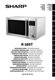
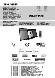
a. The kitchen cabinet must be of the following dimensions as shown in Fig. 1.<br />
WIDTH : 560 mm - 568 mm<br />
HEIGHT : 468 mm<br />
DEPTH : 550 mm - 580 mm<br />
b. Make sure that the back wall of the cupboard D is always fitted to ensure the correct ventilation of<br />
the oven and that the ventilation gap C is 45 mm as shown in Figs 1 and 2.<br />
c. The shelf of the kitchen cabinet should be made to withstand the weight of the microwave oven to<br />
be installed and the heaviest item likely to be cooked in the microwave oven. Refer to the operation<br />
manual for microwave oven weight.<br />
5. Installation near to a conventional oven<br />
a. When a microwave oven is to be installed next to a conventional oven, sufficient space between them<br />
should be allowed to prevent overheating as the surround can warp with excessively high temperatures.<br />
Obviously, it is important to adhere strictly to the conventional oven manufacturer's<br />
installation instructions.<br />
b. A built-in microwave oven must not be installed above a conventional oven otherwise the microwave<br />
oven's cooling system may be adversely affected by hot air produced by the conventional oven.<br />
6. Installation near a refrigerator or freezer<br />
a. If the microwave oven is to be installed above a refrigerator or freezer requiring back ventilation, a<br />
ventilation duct behind the microwave oven must be provided. It is essential that the refrigerator/<br />
freezer manufacturer's installation procedures are followed.<br />
b. Do not install the microwave oven above a refrigerator or freezer which are ventilated at the front.<br />
7. Fixing<br />
To avoid any possibility of the kitchen cabinet moving when the microwave oven is installed, it is<br />
essential that the kitchen cabinet is fixed to the back wall.<br />
8. Adjustment and repair<br />
It is dangerous for your oven to be adjusted or repaired by anyone except properly qualified service<br />
technicians trained by <strong>Sharp</strong>.<br />
If the appliance is ever removed from the cabinet it should be re-installed in accordance with these<br />
instructions, which should be kept in a safe place for future reference.<br />
The manufacturer and/or the distributors of this product cannot be held liable for any damages to<br />
the microwave oven and/or the built-in kit caused by improper installation or adjustment.<br />
ESPAÑOL<br />
ITALIANO NEDERLANDS FRANÇAIS<br />
DEUTSCH<br />
ENGLISH<br />
1
INSTALLATION INSTRUCTIONS<br />
1. (For U.K. use)<br />
A cut-out will have to be provided in the side of the kitchen cabinet for the plug of the oven.<br />
N.B.The mains plug must be accessible after installation or an all-pole switch disconnection must be<br />
provided with a contact separation of at least 3 mm in each pole.<br />
(For Continental use)<br />
The electric outlet must be installed at 150 mm high from the floor of the built-in cabinet and at 50 mm<br />
from the right wall of the built-in cabinet as shown in Fig. 1. The mains plug must be accessible after<br />
installation or the oven must be connected to an electric circuit provided with an all-pole switch (contact<br />
gap no less than 3 mm) to disconnect the oven in case of danger. A safety-device like a fuse in the<br />
installation may be used as a switch.<br />
2. Remove the built-in kit from the package.<br />
3. Set the spacing brackets 1 on the shelf along the right and left walls of the kitchen cabinet, adjusting<br />
the front ends of the shelf and the spacing brackets, and attach them with the four screws B, as<br />
shown in Fig.1.<br />
Caution: The arrow marks on each spacing bracket should be pointing towards you.<br />
4. Place the exhaust duct 2 on the ceiling of the kitchen cabinet along the back wall of the cupboard D and<br />
left wall of the kitchen cabinet without the clearance as shown in Fig.1 and 2. Secure to the ceiling of the<br />
kitchen cabinet with two screws B from below as shown in Fig. 3.<br />
5. Remove the backing paper from the cushion 6. Attach the cushion 6 to the edge of the exhaust duct<br />
3 as shown in Fig. 4.<br />
6. Insert two tabs of the exhaust duct 2 into the slits of the exhaust duct 3. And fold the tabs.<br />
7. Remove the screw E from the oven as shown in Fig. 5.<br />
8. Let the power supply cord pass through the hole of the lower side of the intake duct 4 as shown in Fig. 6.<br />
9. Install the intake duct 4 to the rear of the oven with two screws C and E (removed at step 7) as shown<br />
in Fig. 6.<br />
Caution: Avoid pinching the power supply cord between the oven and the intake duct 4.<br />
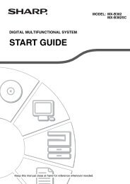
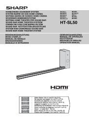
10. Install the intake duct 5 to the rear of the oven with three screws C as shown in Fig. 7.<br />
Caution: Avoid pinching the power supply cord between the oven and the intake duct 4.<br />
11. Remove the backing paper from the three cushions 7, 8 and 9. Attach the cushion 7 at the left side along<br />
the intake duct 4 then attach the cushion 8 at the top of the intake duct 4, and along the left side of the<br />
cushion 7 and the oven as shown in Figs. 8-a and 8-b. Attach the cushion 9 to the top of the oven as shown<br />
in Figs 8-a and 8-b.<br />
12. (For U.K. use)<br />
Place the oven on a table/stand positioned in front of the kitchen cabinet. If you do not prepare the table/<br />
stand, two persons are required. One to hold the oven whilst the other feeds the power supply cord<br />
through the prepared cut out.<br />
(For Continental use)<br />
Place the oven on a table/stand positioned in front of the kitchen cabinet.<br />
If you do not prepare the table/stand, two persons are required. One to hold the oven whilst the other<br />
connects it to the power supply.<br />
13. Connect the oven to the power supply.<br />
Caution: a. In U.K., connect the oven to the power supply 230-240 V, 50 Hz.<br />
b. In the Continent, connect the oven to the power supply 230 V, 50 Hz.<br />
14. Make sure the oven is on the spacing brackets on the shelf of the kitchen cabinet. Then adjust the position<br />
of the oven so that the feet of the oven are fitted into the recesses of the spacing brackets as shown in<br />
Fig. 2.<br />
Caution: Make sure that the power supply cord does not touch the air vent openings behind the oven.<br />
15. Place the built-in frame element 0 on top of the oven making sure that it is level both vertically and<br />
horizontally. Secure loosely to the kitchen cabinet with two screws D as shown in Fig. 9.<br />
16. Insert two built-in frame side elements A between the built-in frame element 0 and the kitchen cabinet.<br />
And secure two screws D tightly as shown in Fig. 9. Check location by measuring distance between right<br />
and left built-in frame side elements A. The distance is stated in Fig. 10.<br />
Note: Fit the hole of the built-in frame side element A to the screw D when inserting.<br />
17. Install the second built-in frame element 0 over the built-in frame side elements A at bottom edge of the<br />
oven. And secure the built-in frame element 0 through the holes of the built-in frame side elements A<br />
to the kitchen cabinet with two screws D as shown in Fig. 9.<br />
Caution: Make sure that 6.5 mm of the frames (upper and lower) and cabinet overlap each other as<br />
shown in Fig. 11, or the kitchen cabinet door may touch the built-in frame elements.<br />
2
Anleitung zum SHARP-Einbausatz <strong>EBR</strong>-<strong>99ST</strong>/<strong>EBR</strong>-<strong>9900</strong> (W)/(<strong>SL</strong>)/(BK)/<strong>EBR</strong>-9910(<strong>SL</strong>)<br />
Lesen und überprüfen Sie die folgenden Punkte vor Installation des SHARP Mikrowellengerätes.<br />
SICHERHEITSHINWEISE<br />
1. Mit Ausnahme von Großbritannien, für die Verwendung in Kontinental-Europa vorgesehen.<br />
Das Gerät muss an einen Stromkreis mit einem Schalter angeschlossen werden (Kontaktabstand<br />
mind. 3 mm), um das Gerät im Gefahrenfall abschalten zu können. Eine Sicherung in der Installation<br />
kann als Schalter verwendet werden.<br />
2. Vor Installation des Gerätes den Netzstecker ziehen.<br />
3. Einbausatz<br />
a. Versichern Sie sich, dass <strong>EBR</strong>-<strong>99ST</strong>/<strong>EBR</strong>-<strong>9900</strong>/<strong>EBR</strong>-9910 der richtige Einbausatz für Ihr Gerät ist.<br />
b. Die Mikrowellengeräte von <strong>Sharp</strong> können bündig als Standgerät auf einer Küchenplatte aufgestellt<br />
oder unter Verwendung des Einbausatzes in einen Küchenschrank eingebaut werden.<br />
c. Die Umgebung des <strong>EBR</strong>-<strong>99ST</strong>/<strong>EBR</strong>-<strong>9900</strong>/<strong>EBR</strong>-9910 wird heiß, wenn das Gerät mit Heizelementen<br />
betrieben wird. Vorsicht vor Verbrennungen beim Betrieb des Gerätes.<br />
4. Einbauschrank<br />
Den Einbauschrank folgendermaßen vorbereiten;<br />
a. Der Einbauschrank muss folgende Abmessungen aufweisen, siehe Fig. 1.<br />
BREITE : 560 mm - 568 mm<br />
HÖHE : 468 mm<br />
TIEFE : 550 mm - 580 mm<br />
b. Um eine ausreichende Belüftung des Gerätes zu gewährleisten, ist sicherzustellen, dass die Rückwand<br />
des Einbauschrankes D vorhanden ist und dass der Belüftungsabstand C wie in Fig. 1 und 2 gezeigt<br />
45 mm beträgt.<br />
c. Der Boden des Einbauschrankes muss so konstruiert sein, dass er das Gewicht des zu installierenden<br />
Gerätes und der darin zubereiteten Lebensmittel tragen kann. Beachten Sie das Gewicht des<br />
Mikrowellengerätes in der Bedienungsanleitung.<br />
5. Installation in der Nähe eines konventionellen Herdes<br />
a. Wenn ein Mikrowellengerät neben einem konventionellen Herd installiert wird, muss zum Schutz vor<br />
Überhitzen ein ausreichender Abstand zwischen den beiden Geräten eingehalten werden, da der<br />
Einbausatz sich bei übermäßig hohen Temperaturen verziehen kann. Die Installationsanweisungen<br />
für den konventionellen Herd müssen unbedingt beachtet werden.<br />
b. Ein Einbau-Mikrowellengerät darf nicht über einem konventionellen Herd installiert werden, da das<br />
Kühlungssystem des Mikrowellengerätes durch Heißluft, die vom konventionellen Herd erzeugt<br />
wird, beschädigt werden kann.<br />
6. Installation in der Nähe eines Kühlschrankes oder eines Gefriergerätes<br />
a. Wenn das Mikrowellengerät über einem Kühlschrank oder einem Gefriergerät installiert wird, für die<br />
eine rückwärtige Belüftung notwendig ist, muss für die Belüftung ein Belüftungskanal hinter dem<br />
Mikrowellengerät angebracht werden. Die Installationsanweisungen für den Kühlschrank oder für<br />
das Gefriergerät müssen unbedingt beachtet werden.<br />
b. Das Mikrowellengerät darf nicht über einem Kühlschrank oder einem Gefriergerät installiert werden,<br />
die an der Frontseite belüftet werden.<br />
7. Befestigung<br />
Um Bewegungen des Einbauschrankes nach der Installation des Mikrowellengerätes zu vermeiden,<br />
muss er stabil an der rückwärtigen Wand befestigt werden.<br />
8. Einstellung und Reparatur<br />
Es ist gefährlich, das Gerät von einer anderen Person als einem autorisierten und von <strong>Sharp</strong> ausgebildeten<br />
Wartungstechniker einstellen oder reparieren zu lassen.<br />
Wenn das Gerät aus einem Einbauschrank entfernt wird, muss es bei Wiedereinbau entsprechend dieser<br />
Anleitung installiert werden. Deshalb für zukünftigen Gebrauch die Anleitung an einem sicheren Ort<br />
aufbewahren.<br />
ESPAÑOL<br />
ITALIANO NEDERLANDS FRANÇAIS<br />
DEUTSCH<br />
ENGLISH<br />
Der Hersteller bzw. der Vertreiber dieses Produktes ist nicht verantwortlich für Beschädigungen des<br />
Mikrowellengerätes oder des Einbausatzes, die durch eine falsche Installation oder Einstellung<br />
verursacht werden.<br />
3
INSTALLATIONSANLEITUNG<br />
1. (Für Großbritannien)<br />
Für den Netzstecker muss auf der Seite des Einbauschrankes eine Öffnung gebohrt werden.<br />
Hinweis: Der Hauptnetzstecker muss nach der Installation zugänglich sein oder es muss ein<br />
Abtrennschalter vorhanden sein, bei dem die Kontakte an jedem Pol mindestens 3 mm<br />
voneinander entfernt sind.<br />
(Für Kontinental-Europa)<br />
Die Netzsteckdose muss 150 mm über dem Boden des Einbauschrankes installiert werden und 50 mm<br />
von der rechten Wand, wie in Fig. 1 gezeigt. Der Hauptnetzstecker muss nach der Installation zugänglich<br />
sein oder das Gerät muss an einen elektrischen Schaltkreis mit einem Abtrennschalter (Kontaktabstand<br />
mind. 3 mm) angeschlossen sein, um das Gerät im Gefahrenfall abschalten zu können. Eine Sicherung<br />
als Schutzvorrichtung kann bei der Installation als ein Schalter verwendet werden.<br />
2. Den Einbausatz aus der Verpackung nehmen.<br />
3. Die Abstandshalter 1 entlang der rechten und linken Wand des Einbauschrankes auf den Boden legen,<br />
die Bodenvorderkante und die Abstandshalter positionieren und mit den vier Schrauben B wie in Fig.<br />
1 gezeigt anbringen.<br />
Vorsicht: Die Pfeile auf den Abstandhaltern müssen nach vorne weisen.<br />
4. Den Entlüftungskanal 2 an der Decke hinten links des Einbauschrankes D anbringen ohne Abstand zur<br />
Seitenwand, wie in Fig. 1 und Fig. 2 gezeigt. Mit den beiden Schrauben B wird der Entlüftungskanal von<br />
unten an der Decke des Einbauschrankes befestigt, wie in Fig. 3 gezeigt.<br />
5. Den Schutzstreifen von dem Schaumstoffteil 6 enternen. Das Schaumstoffteil 6 am Entlüftungskanal<br />
3 wie in Fig. 4 gezeigt anbringen.<br />
6. Die zwei Laschen am Entlüftungskanal 2 in die Schlitze des Entlüftungskanals 3 einschieben und die<br />
Laschen umbiegen.<br />
7. Die Schraube E wie in Fig. 5 gezeigt vom Gerät abnehmen.<br />
8. Das Netzkabel wie in Fig. 6 gezeigt durch das Loch in der Unterseite des Ansaugkanals 4 führen.<br />
9. Den Ansaugkanal 4 wie in Fig. 6 gezeigt mit den beiden Schrauben C und E (unter Schritt 7<br />
abgenommen) an der Rückseite des Gerätes befestigen.<br />
Vorsicht: Darauf achten, dass das Netzkabel nicht zwischen dem Gerät und dem Ansaugkanal 4<br />
eingeklemmt wird.<br />
10. Den Ansaugkanal 5 auf der Rückseite des Gerätes mit den drei Schrauben C wie in Fig. 7 gezeigt anbringen.<br />
Vorsicht: Darauf achten, dass das Netzkabel nicht zwischen dem Gerät und dem Ansaugkanal 4<br />
eingeklemmt wird.<br />
11. Die Schutzstreifen von den drei Schaumstoffteilen 7, 8 und 9 abziehen. Das Schaumstoffteil 7 auf der<br />
linken Seite des Ansaugkanals 4, das Schaumstoffteil 8 auf der Oberseite des Ansaugkanals 4 auf der<br />
linken Seite von Schaumstoffteil 7 und Gerät wie in Fig. 8-a und 8-b gezeigt anbringen. Das Schaumstoffteil<br />
9 oben auf dem Gerät anbringen wie in Fig. 8-a und 8-b gezeigt.<br />
12. (Für Großbritannien)<br />
Stellen Sie das Gerät auf einen Tisch/Auflagefläche vor die Einbau-Öffnung des Einbauschrankes. Wenn<br />
kein Tisch/Auflagefläche vorbereitet ist, werden zwei Personen benötigt, einer, der das Mikrowellengerät<br />
hält, während die andere Person die Netzanschlussleitung durch die vorbereitete Öffnung führt.<br />
(Für Kontinental-Europa)<br />
Stellen Sie das Mikrowellengerät auf einen Tisch vor den Einbauschrank. Wenn Sie keinen Tisch zur<br />
Verfügung haben, werden 2 Personen benötigt. Eine Person zum Tragen des Gerätes, während die<br />
andere Person das Gerät an die Steckdose anschließt.<br />
13. Das Gerät an die Stromversorgung anschließen.<br />
Vorsicht: a. In Großbritannien muss das Gerät an 230-240V, 50Hz Wechselstrom angeschlossen werden.<br />
b. In Kontinental-Europa muss das Gerät an eine Steckdose mit 230V, 50Hz, Wechselstrom<br />
angeschlossen werden.<br />
14. Stellen Sie sicher, dass das Gerät richtig auf den Abstandshaltern, auf dem Boden des Einbauschrankes,<br />
steht. Dann richten Sie das Gerät so aus, dass die Füße des Gerätes in die Aussparungen der Abstandshalter<br />
passen, wie in Fig. 2 gezeigt.<br />
Vorsicht:<br />
Sicherstellen, dass das Netzkabel nicht mit den Lüftungsöffnungen auf der Rückseite des<br />
Gerätes in Berührung kommt.<br />
15. Das Rahmenbauteil 0 auf das Gerät aufsetzen und darauf achten, dass das Teil sich vertikal und horizontal<br />
in der Waage befindet. Am Einbauschrank lose mit den zwei Schrauben D wie in Fig. 9 gezeigt anbringen.<br />
16. Zwei seitliche Rahmenbauteile A zwischen die Rahmenbauteile 0 und den Einbauschrank schieben. Die<br />
zwei Schrauben D wie in Fig. 9 gezeigt fest anschrauben. Die Aufstellung durch Messung des Abstands<br />
zwischen dem rechten und linken eingebauten seitlichen Rahmenbauteil A prüfen. Der Abstand ist in Fig.<br />
10 angezeigt.<br />
Hinweis: Beim Einschieben die Öffnung des eingebauten seitlichen Rahmenbauteils A mit der Schraube<br />
D angleichen.<br />
17. Das zweite Rahmenbauteil 0 über dem eingebauten seitlichen Rahmenbauteil A auf der Unterkante des<br />
Gerätes anbringen. Den Rahmenbauteil 0 durch die Öffnungen des seitlichen Rahmenbauteils A am<br />
Einbauschrank mit den zwei Schrauben D wie in Fig. 9 gezeigt befestigen.<br />
Vorsicht:<br />
Sicherstellen, dass der Rahmen (oben und unten) den Schrank wie in Fig. 11 gezeigt um nur<br />
6,5 mm überlappt. Anderenfalls kann es vorkommen, dass die Einbauschranktür die<br />
Rahmenbauteile berührt.<br />
4
Instructions pour le lot de pièces SHARP <strong>EBR</strong>-<strong>99ST</strong>/<strong>EBR</strong>-<strong>9900</strong> (W)/(<strong>SL</strong>)/<br />
(BK)/<strong>EBR</strong>-9910(<strong>SL</strong>)<br />
Lire et vérifier les points suivants avant d'installer le four à micro-ondes.<br />
CONSIGNES DE SÉCURITÉ<br />
1. Pour utilisation sur le continent européen seulement (Royaume-Uni exclu).<br />
Le four doit être connecté à un circuit électrique équipé d'un interrupteur (distance entre contacts au<br />
moins égale à 3 mm) permettant de débrancher le four en cas de danger. Un dispositif de sécurité<br />
compris dans l'installation peut être utilisé comme interrupteur.<br />
2. Isoler le four du réseau de distribution électrique avant l'installation.<br />
3. Installation<br />
a. S'assurer que le lot <strong>EBR</strong>-<strong>99ST</strong>/<strong>EBR</strong>-<strong>9900</strong>/<strong>EBR</strong>-9910 est le cadre qui convient au four.<br />
b. Les fours à micro-ondes de marque SHARP sont conçus pour être installés soigneusement sur le haut<br />
d'une armoire de cuisine ou montés dans un placard de cuisine convenable avec utilisation du cadre.<br />
c. Le cadre <strong>EBR</strong>-<strong>99ST</strong>/<strong>EBR</strong>-<strong>9900</strong>/<strong>EBR</strong>-9910 s'échauffe lorsque les résistances du four sont mises en<br />
service. Veiller à ne pas se brûler pendant l'utilisation du four.<br />
4. Placard de cuisine<br />
Préparer le placard de cuisine comme suit:<br />
a. Le placard doit présenter les dimensions suivantes, comme il est montré sur la figure 1.<br />
LARGEUR : 560 mm - 568 mm<br />
HAUTEUR : 468 mm<br />
PROFONDEUR : 550 mm - 580 mm<br />
b. S'assurer que la paroi arrière D est posée de manière que le four soit correctement ventilé et que<br />
l'ouverture d'aération C soit égale à 45 mm comme le montrent les figures 1 et 2.<br />
c. La tablette du placard de cuisine doit être assez solide pour qu'elle supporte le poids du four à microondes.<br />
Se référer au manuel d'utilisation pour le poids du four à micro-ondes.<br />
5. Installation à côté d'un four conventionnel<br />
a. Lorsqu'un four à micro-ondes est installé à côté d'un four conventionnel, l'espace laissé entre les<br />
deux doit être suffisant pour éviter la déformation du cadre du premier, en raison de la température.<br />
Il est évidemment important d'observer strictement les instructions d'installation données par le<br />
constructeur du four conventionnel.<br />
b. Le four à micro-ondes ne doit pas être installé au dessus d'un four conventionnel, sinon le système<br />
de refroidissement peut être endommagé par l'air chaud produit par le four conventionnel.<br />
6. Installation au-dessus d'un réfrigérateur ou d'un congélateur<br />
a. Si le four à micro ondes est placé au-dessus d'un réfrigérateur ou un congélateur nécessitant une<br />
ventilation arrière, un conduit de ventilation derrière le four à micro-ondes doit être prévu. Il est<br />
essentiel que les procédures d'installation des fabricants des réfrigérateurs et congélateurs soient<br />
suivies.<br />
b. Ne pas installer le four à micro-ondes au-dessus d'un réfrigérateur ou d'un congélateur avec<br />
ventilation avant.<br />
7. Fixation<br />
Afin d'éviter tout risque de mouvement du placard une fois que le four à micro-ondes y est installé, il<br />
est essentiel que ce premier soit fixé au mur arrière.<br />
8. Réglage et réparation<br />
Il est dangereux que le four à micro-ondes soit réglé et réparé par une personne autre qu'un technicien<br />
formé par SHARP.<br />
Si le four doit être retiré du placard, sa réinstallation doit être conforme à ces instructions qu'il est prudent<br />
de conserver dans ce dessein.<br />
ESPAÑOL<br />
ITALIANO NEDERLANDS FRANÇAIS<br />
DEUTSCH<br />
ENGLISH<br />
Le fabricant et/ou les distributeurs de ce produit ne saurait être tenu pour responsable de tout<br />
dommage au four à micro-ondes et/ou au kit intégré survenu à la suite d'une installation ou d'un<br />
réglage incorrect.<br />
5
INSTRUCTIONS POUR L'INSTALLATION<br />
1. (Pour l'emploi au Royaume-Uni)<br />
Une petite découpe devra être prévue sur le côté du placard de cuisine pour pour la fiche du cordon<br />
d'alimentation.<br />
N.B.:<br />
La prise secteur doit être accessible après installation, ou encore un disjoncteur multipolaire<br />
doit être prévu, disjoncteur pour lequel la distance entre contacts est au moins de 3 mm.<br />
(Pour l'emploi sur le continent)<br />
La prise secteur doit être installée à 150 mm au-dessus du fond du placard intégré et à 50 mm du panneau<br />
droit de ce placard, comme le montre la figure 1. La prise secteur doit être accessible après installation,<br />
ou encore le four doit être raccordé à un circuit électrique muni d'un disjoncteur multipolaire (distance<br />
entre contacts au moins égale à 3 mm) permettant d'isoler le four en cas de danger. Un dispositif de<br />
sécuríté tel qu'un fusible peut être utilisé dans l'installation comme coupe-circuit.<br />
2. Retirer toutes les pièces de l'emballage.<br />
3. Poser les supports d’entretoise 1 sur la tablette du placard de cuisine contre les parois droite et gauche<br />
en ajustant les bords avant de la tablette et des entretoises, puis fixer ces entretoises au moyen des quatre<br />
vis B comme le montre la figure 1.<br />
Attention: Les flèches que portent les entretoises doivent être dirigées vers soi.<br />
4. Placer le conduit d’évacuation 2 à la partie supérieure du placard de cuisine, le long de la paroi arrière<br />
D et de la cloison gauche du placard, de manière qu’il n’y ait aucun jeu, comme le montrent les figures<br />
1 et 2. Fixer-le par le dessous à la partie supérieure du placard au moyen des deux vis B, comme le montre<br />
la figure 3.<br />
5. Retirer la feuille de protection du support 6. Attacher le coussin 6 sur le conduit d’évacuation 3 comme<br />
le montre la figure 4.<br />
6. Insérer deux languettes du conduit d’évacuation 2 dans les fentes du conduit d’évacuation 3 et tordre<br />
les languettes.<br />
7. Retirer la vis E du four, comme le montre la figure 5.<br />
8. Faire passer le cordon d'alimentation au travers du trou à la partie inférieure du conduit d'aspiration 4,<br />
comme le montre la figure 6.<br />
9. Installer le conduit d'aspiration 4 à l'arrière du four au moyen des deux vis C et E (retirées au cours de<br />
l'opération 7), comme le montre la figure 6.<br />
Attention: Eviter d'écraser le cordon d'alimentation entre le four et le conduit d'aspiration 4.<br />
10. Installer le conduit d’aspiration 5 à l’arrière du four au moyen des trois vis C comme le montre la figure 7.<br />
Attention: Eviter d'écraser le cordon d'alimentation entre le four et le conduit d'aspiration 4.<br />
11. Retirer la feuille de protection des trois supports 7, 8 et 9. Fixer le support 7 à la gauche du conduit<br />
d’aspiration 4 et fixer le support 8 au sommet du conduit d’aspiration 4, à la gauche du support 7 et<br />
du four, comme le montrent les figures 8-a et 8-b. Fixer le support 9 au sommet du four, comme le<br />
montrent les figures 8-a et 8-b.<br />
12. (Pour l'emploi au Royaume-Uni)<br />
Placer le four sur une tablette ou un support installés à l'avant du placard de cuisine. Si la tablette ou le<br />
support ne sont pas préparés, deux personnes sont nécessaires.<br />
Une pour maintenir le four et l'autre pour faire passer le cordon d'alimentation á travers la découpe<br />
préparée.<br />
(Pour l'emploi sur le continent)<br />
Placer le four sur une tablette ou un support installés à l'avant du placard de cuisine.<br />
Si la tablette ou le support ne sont pas préparés, deux personnes sont nécessaires. Une pour maintenir<br />
le four et l'autre pour le relier au secteur.<br />
13. Brancher le four sur la prise d'alimentation.<br />
Attention: a. Au Royaume-Uni brancher le four sur une prise d'alimentation de 230-240 V, 50 Hz.<br />
b. Sur le continent, brancher le four sur une prise d'alimentation de 230 V, 50 Hz.<br />
14. Veiller à ce que le four soit sur les entretoises de la tablette du placard de cuisine. Cela fait, ajuster la<br />
position du four de manière que les pieds de ce dernier soient bien entrés dans les fentes des supports<br />
d'entretoise comme indiqué dans la figure 2.<br />
Attention:<br />
S'assurer que le cordon d'alimentation n'est pas en contact avec l'ouverture d'aération<br />
située derrière le four.<br />
15. Placer l'élément de cadre intégré 0 au sommet du four en veillant à ce qu'il soit de niveau horizontalement<br />
et verticalement. Le fixer temporairement au placard de cuisine au moyen de deux vis D, comme le<br />
montre la figure 9.<br />
16. Engager deux éléments latéraux de cadre intégré A entre l'élément de cadre intégré 0 et le placard de<br />
cuisine. Serrer à fond les deux vis D, comme le montre la figure 9. Vérifier l'emplacement en mesurant<br />
la distance entre l'élément latéral droit A et l'élément latéral gauche A de cadre intégré. La distance est<br />
indiquée à la figure 10.<br />
Remarque: Engager la vis D dans le perçage de l'élément latéral A de cadre intégré.<br />
17. Installer le deuxième élément de cadre intégré 0 sur les éléments latéraux de cadre intégré A, au bord<br />
inférieur du four. Assurer la fixation de l'élément intégré 0 au placard de cuisine avec les deux vis D<br />
introduites dans les perçages des éléments latéraux de cadre intégré A, comme le montre la figure 9.<br />
Attention: Veiller à ce que les 6,5 mm des cadres (supérieur et inférieur) et le placard se chevauchent,<br />
comme le montre la figure 11. Dans le cas contraire, la porte du placard de cuisine pourrait<br />
toucher les éléments de cadre intégré.<br />
6
Aanwijzingen voor de SHARP inbouwkit <strong>EBR</strong>-<strong>99ST</strong>/<strong>EBR</strong>-<strong>9900</strong> (W)/(<strong>SL</strong>)/(BK)/<strong>EBR</strong>-9910(<strong>SL</strong>)<br />
Lees de volgende punten goed door en controleer dat aan deze punten wordt voldaan alvorens een <strong>Sharp</strong><br />
magnetronoven te installeren.<br />
VEILIGHEIDSINFORMATIE<br />
1. Uitsluitend voor gebruik in Europa (uitgezonderd Groot-Brittannië).<br />
De oven moet op een stopcontact met schakelaar worden aangesloten (contactspleet niet minder dan<br />
3 mm) zodat u de oven bij problemen snel kunt ontkoppelen. Een veiligheidsvoorziening, bijvoorbeeld<br />
een zekering, in de installatie kan tevens als schakelaar dienen.<br />
2. Trek de stekker van de oven uit het stopcontact voordat u de oven gaat installeren.<br />
3. Ombouw<br />
a. Controleer dat de <strong>EBR</strong>-<strong>99ST</strong>/<strong>EBR</strong>-<strong>9900</strong>/<strong>EBR</strong>-9910 de geschikte ombouw voor uw oven is.<br />
b. <strong>Sharp</strong> magnetronovens zijn ontworpen voor plaatsing op een keukenblad of voor inbouw in een<br />
hiervoor geschikte keukenkast met gebruik van de ombouw.<br />
c. De <strong>EBR</strong>-<strong>99ST</strong>/<strong>EBR</strong>-<strong>9900</strong>/<strong>EBR</strong>-9910 ombouw wordt heet wanneer het verwarmingselement(en) van de<br />
oven wordt gebruikt. Let op dat u zich niet verbrandt tijdens het gebruik van de oven.<br />
4. Keukenkast<br />
Let op dat de kast aan de volgende vereisten voldoet:<br />
a. De keukenkast dient de volgende afmetingen te hebben, zoals in Afb. 1 wordt aangegeven.<br />
BREEDTE : 560 mm - 568 mm<br />
HOOGTE : 468 mm<br />
DIEPTE : 550 mm - 580 mm<br />
b. Controleer dat het achterpaneel van de keukenkast D de ventilatie van de oven niet hindert en dat er<br />
tenminste een ventilatie-opening C van 45 mm is zoals in Afb. 1 en 2 aangegeven.<br />
c. De plank van de keukenkast dient sterk genoeg te zijn voor het gewicht van de oven, de schaal en het<br />
zwaarste gerecht dat eventueel in de oven bereid wordt. Zie de gebruiksaanwijzing van de<br />
magnetronoven voor het gewicht.<br />
5. Installatie in de buurt van een conventionele oven<br />
a. Wanneer u de magnetronoven naast een conventionele oven wilt plaatsen, moet er voldoende ruimte<br />
tussen de twee ovens zijn zodat oververhitting wordt voorkomen. De ombouw zou anders namelijk<br />
kunnen vervormen. Let tevens op de installatievoorschriften die in de gebruiksaanwijzing van de<br />
conventionele oven staan vermeld.<br />
b. Een magnetronoven mag niet boven een conventionele oven worden ingebouwd. Het ventilatiesysteem<br />
van de magnetronoven zou anders onjuist kunnen gaan werken vanwege de warmte van de<br />
conventionele oven.<br />
6. Installatie in de buurt van een koelkast of vriezer<br />
a. Indien u de magnetronoven op een koelkast of vriezer die via de achterkant wordt geventileerd wilt<br />
installeren, moet er een ventilatiekanaal achter de magnetronoven zijn. Let tevens op de<br />
installatievoorschriften die in de gebruiksaanwijzing van de koelkast of vriezer staan vermeld.<br />
b. Installeer de magnetronoven niet op een koelkast of vriezer die via de voorkant wordt geventileerd.<br />
7. Bevestiging<br />
De keukenkast moet aan de muur zijn bevestigd zodat wordt voorkomen dat de keukenkast verschuift<br />
tijdens het installeren of gebruik van de magnetronoven.<br />
8. Reparatie en afstellen<br />
Uw oven mag uitsluitend door <strong>Sharp</strong> erkend onderhoudspersoneel worden afgesteld of gerepareerd.<br />
Het zelf repareren van de oven is gevaarlijk.<br />
Bewaar deze aanwijzingen op een veilige plaats. U heeft ze nodig wanneer u ooit de oven op een andere<br />
plaats wilt installeren.<br />
ESPAÑOL<br />
ITALIANO NEDERLANDS FRANÇAIS<br />
DEUTSCH<br />
ENGLISH<br />
De fabrikant en/of verkoper van dit product kan niet aansprakelijk worden gesteld voor eventuele<br />
beschadigingen aan de magnetronoven en/of de inbouwkit als gevolg van een verkeerde montage<br />
of afstelling.<br />
7
AANWIJZINGEN VOOR INSTALLATIE<br />
1. (Voor gebruik in Groot-Brittannië)<br />
Er dient een uitsparing voor de stekker van de oven in het zijpaneel van de keukenkast te worden gemaakt.<br />
Belangrijk: Zorg dat de netstekker na de installatie toegankelijk is of dat er een twee-pool<br />
onderbrekingsschakelaar in het circuit is opgenomen met een contact-spleet van minstens<br />
3 mm in iedere pool.<br />
(Voor gebruik in Europa)<br />
De elektriciteitsaansluiting moet zich op 150 mm hoogte vanaf de vloer van de inbouwkast en 50 mm<br />
vanaf de rechterkant van de inbouwkast bevinden zoals in Afb. 1 wordt getoond. Zorg dat de netstekker<br />
na de installatie toegankelijk is of dat de oven op een elektrisch circuit is aangesloten dat voorzien is van<br />
een twee-pool onderbrekingsschakelaar (contact-spleet niet minder dan 3 mm) om de stroomvoorziening<br />
naar de oven te kunnen verbreken in geval van gevaar. Een veiligheidsvoorziening zoals een zekering kan<br />
gebruikt worden als onderbrekingsschakelaar.<br />
2. Verwijder de verpakking van de inbouwkit.<br />
3. Plaats de afstandsbeugels 1 op de plank in lijn met de rechter- en linkerpanelen van de keukenkast. Stel<br />
de voorkanten van de plank en de afstandsbeugels af en bevestig de beugels met de vier schroeven B<br />
zoals in Afb. 1 wordt getoond.<br />
Let op: De pijlen op de beugels dienen naar u toe te wijzen.<br />
4. Plaats het uitlaatkanaal 2 op de bovenkant van de keukenkast tegen de achterkant D en de linkerkant van<br />
de kast. Plaats zodanig dat er geen speling is, zoals in Afb. 1 en 2 wordt getoond. Zet aan de bovenkant<br />
van de keukenkast vast met twee schroeven B. Schroef vanaf de onderkant, zoals in Afb. 3 aangegeven.<br />
5. Verwijder de beschermlaag van het kussen 6. Bevestig het kussen 6 tegen het uitlaatkanaal 3 zoals in<br />
Afb. 4 wordt getoond.<br />
6. Steek de twee lipjes van het uitlaatkanaal 2 in de openingen van het uitlaatkanaal 3. Vouw de lipjes om.<br />
7. Verwijder de schroef E van de oven zoals u in Afb. 5 ziet.<br />
8. Haal het netsnoer door de opening aan de onderkant van het inlaatkanaal 4 zoals u in Afb. 6 ziet.<br />
9. Plaats het inlaatkanaal 4 met de twee schroeven C en E (die u in stap 7 heeft verwijderd) aan de<br />
achterkant van de oven zoals u in Afb. 6 ziet.<br />
Let op: Klem het netsnoer niet tussen de oven en het inlaatkanaal 4 vast.<br />
10. Bevestig het inlaatkanaal 5 met de drie schroeven C aan de achterkant van de oven zoals in Afb. 7 wordt<br />
getoond.<br />
Let op: Klem het netsnoer niet tussen de oven en het inlaatkanaal 4 vast.<br />
11. Verwijder het papier van de drie kussens 7, 8 en 9. Bevestig het kussen 7 aan de linkerkant van het<br />
inlaatkanaal 4 en bevestig het kussen 8 aan de bovenkant van het inlaatkanaal 4, aan de linkerkant van<br />
het kussen 7 en aan de oven zoals in Afb. 8-a en 8-b wordt getoond. Bevestig kussen 9 aan de bovenkant<br />
van de oven zoals u in Afb. 8-a en 8-b ziet.<br />
12. (Voor gebruik in Groot-Brittannië)<br />
Plaats de oven op een tafel/kastje dat u voor de keukenkast heeft gezet.<br />
Als u geen tafel/kastje gebruikt, zijn er twee personen nodig. Een persoon om de oven vast te houden en<br />
een tweede persoon om het netsnoer door de reeds gemaakte opening te leiden.<br />
(Voor gebruik in Europa)<br />
Plaats de oven op een tafel/kastje dat u voor de keukenkast heeft gezet.<br />
Als u geen tafel/kastje gebruikt, zijn er twee personen nodig. Een persoon om de oven vast te houden en<br />
een tweede persoon om het netsnoer aan te sluiten.<br />
13. Steek de stekker van het netsnoer van de oven in een stopcontact.<br />
Let op:<br />
a. In Groot-Brittannië, verbind de oven met een 230-240 V, 50 Hz spanningsbron.<br />
b. In Europa, verbind de oven met een 230 V, 50 Hz spanningsbron.<br />
14. Controleer of de oven op de afstandsbeugels op de plank van de keukenkast staat. Stel vervolgens de<br />
positie van de oven af zodat de voetjes van de oven in de uitsparingen van de afstandsbeugels passen<br />
zoals in Afb. 2 wordt getoond.<br />
Let op: Controleer dat het netsnoer geen contact met de ventilatie-openingen achter de oven maakt.<br />
15. Plaats het inbouwframe-element 0 boven de oven. Kontroleer dat het zowel horizontaal als vertikaal<br />
recht zit. Maak met twee schroeven D tijdelijk aan de keukenkast vast zoals in Afb. 9 wordt getoond.<br />
16. Steek de twee inbouwframe-elementen voor de zijkanten A tussen het inbouwframe-element 0 en de<br />
keukenkast. Draai vervolgens de twee schroeven D stevig vast zoals in Afb. 9 wordt getoond. Controleer<br />
de plaats door de afstand tussen de rechter en linker inbouwframe-elementen voor de zijkanten A te<br />
meten. De afstand is aangegeven in Afb. 10.<br />
Opmerking: Lijn het gat van het inbouwframe-element voor de zijkant A uit met de schroef D bij het<br />
insteken.<br />
17. Breng het tweede inbouwframe-element 0 aan op de inbouwframe-elementen voor de zijkanten A<br />
onder de oven. Maak het inbouwframe-element 0 vervolgens via de gaten van de inbouwframeelementen<br />
voor de zijkanten A vast aan de keukenkast met de twee schroeven D zoals in Afb. 9 wordt<br />
getoond.<br />
Let op:<br />
Kontroleer dat 6,5 mm van de frames (boven en onder) en de kast elkaar overlappen zoals<br />
in Afb. 11 wordt getoond, daar anders de deur van de keukenkast mogelijk de inbouwframeelementen<br />
raakt.<br />
8
Istruzioni per il kit <strong>EBR</strong>-<strong>99ST</strong>/<strong>EBR</strong>-<strong>9900</strong> (W)/(<strong>SL</strong>)/(BK)/<strong>EBR</strong>-9910(<strong>SL</strong>) incorporato SHARP<br />
Prima di installare un forno a microonde <strong>Sharp</strong>, leggete e controllare i punti seguenti.<br />
INFORMAZIONI RIGUARDANTI LA SICUREZZA<br />
1. Per l'uso nell'Europa continentale soltanto, Gran Bretagna eccettuata.<br />
Il forno deve essere collegato ad un circuito elettrico dotato di un interruttore (distanza tra i contatti<br />
non inferiore ai 3 mm), in modo da poter isolare elettricamente il forno in caso di pericolo.<br />
Nell'installazione, come interruttore si può usare un dispositivo di sicurezza quale un fusibile.<br />
2. Staccate il cavo di alimentazione del forno dalla presa di corrente prima dell'installazione.<br />
3. Telaio<br />
a. Accertatevi che l'<strong>EBR</strong>-<strong>99ST</strong>/<strong>EBR</strong>-<strong>9900</strong>/<strong>EBR</strong>-9910 sia il telaio corretto per il vostro forno.<br />
b. I forni a microonde <strong>Sharp</strong> sono progettati per essere installati comodamente su un ripiano della<br />
cucina, oppure per essere incorporati all'interno di un armadietto della cucina usando il telaio.<br />
c. La parte attorno <strong>EBR</strong>-<strong>99ST</strong>/<strong>EBR</strong>-<strong>9900</strong>/<strong>EBR</strong>-9910 diventa calda da scottare quando il forno utilizza i<br />
riscaldatori. Fare attenzione a non scottarsi nell'adoperare il forno.<br />
4. Armadietto della cucina<br />
Preparate l'armadietto della cucina nel modo seguente:<br />
a. L'armadietto della cucina deve avere le dimensioni seguenti, come mostrato nella Fig. 1.<br />
Larghezza : 560 mm - 568 mm<br />
Altezza : 468 mm<br />
Profondità : 550 mm - 580 mm<br />
b. Accertatevi che la parete posteriore dell'armadietto D consenta sempre la ventilazione adeguata del<br />
forno e che l'apertura di ventilazione C sia di 45 mm, come mostrato nelle Fig. 1 e 2.<br />
c. Il ripiano dell'armadietto della cucina deve essere in grado di sopportare il peso del forno a microonde<br />
e del cibo più pesante che si possa cucinare. Per il peso del forno a microonde riferitevi al suo manuale<br />
di istruzioni.<br />
5. Installazione vicino ad un forno convenzionale<br />
a. Se si installa il forno a microonde vicino ad un forno convenzionale, tra di essi si dovrebbe lasciare<br />
uno spazio sufficiente in modo da prevenire il surriscaldamento, perché il telaio potrebbe deformarsi<br />
con le temperature eccessivamente alte. Ovviamente, è molto importante osservare strettamente le<br />
istruzioni sull'installazione del fabbricante del forno.<br />
b. Il forno a microonde non deve essere installato sopra un forno convenzionale, perché altrimenti l'aria<br />
calda prodotta da quest'ultimo potrebbe danneggiare il sistema di raffreddamento del forno a<br />
microonde.<br />
6. Installazione vicino a un frigorifero o un congelatore<br />
a. Se si deve installare il forno a microonde sopra un frigorifero o un congelatore aventi il sistema di<br />
ventilazione posteriore, bisogna installare un condotto di ventilazione dietro il forno a microonde.<br />
Bisogna assolutamente osservare strettamente le procedure di installazione del fabbricante del<br />
frigorifero/congelatore.<br />
b. Non installate il forno a microonde sopra un frigorifero o congelatore aventi il sistema di ventilazione<br />
anteriore.<br />
7. Fissaggio<br />
Per evitare assolutamente che l'armadietto della cucina si sposti quando si installa il forno a microonde,<br />
esso deve essere fissato alla parete posteriore.<br />
8. Regolazione e riparazione<br />
La regolazione o la riparazione del forno a microonde che non sia effettuata da personale tecnico<br />
addestrato da <strong>Sharp</strong> è molto pericolosa.<br />
Se si toglie il forno a microonde dall'armadietto, esso deve essere installato di nuovo secondo queste<br />
istruzioni che vanno conservate in un posto sicuro per riferimenti futuri.<br />
ESPAÑOL<br />
ITALIANO NEDERLANDS FRANÇAIS<br />
DEUTSCH<br />
ENGLISH<br />
Il produttore e/o i distributori di questo prodotto non si assumono alcuna responsabilità per<br />
eventuali danni al forno a microonde e/o al kit incorporato causati da uso improprio durante<br />
l'installazione o la regolazione.<br />
9
ISTRUZIONI PER L'INSTALLAZIONE<br />
1. (Per l'uso in Gran Bretagna)<br />
Sul fianco dell'armadietto da cucina si deve praticare una apertura per la spina del cavo di alimentazione.<br />
Nota Bene: La spina di corrente deve essere accessibile dopo l'installazione, oppure bisogna<br />
provvedere un interruttore automatico multipolare con una distanza tra i contatti di<br />
almeno 3 mm.<br />
(Per l'uso nell'Europa continentale)<br />
La presa di corrente deve essere installata a 150 mm dal piano inferiore dell'armadietto e a 50 mm dalla<br />
parete destra dell'armadietto incorporato, come mostrato nella Fig. 1. La spina di corrente deve essere<br />
accessibile dopo l'installazione, oppure il forno deve essere collegato ad un circuito elettrico dotato di<br />
interruttore automatico multipolare (con una distanza tra i contatti non inferiore a 3 mm), per poter isolare<br />
il forno in caso di pericolo. Come valvola di sicurezza si può installare un dispositivo quale un fusibile.<br />
2. Togliete il kit incorporato dalla scatola d'imballaggio.<br />
3. Sistemate le staffe distanziali 1 sul ripiano lungo le pareti destra e sinistra dell'armadietto da cucina,<br />
regolando le estremità anteriori del ripiano e le staffe distanziali, e fissatele con le quattro viti B come<br />
mostrato nella Fig. 1.<br />
Nota: La freccia su ciascuna staffa distanziale deve essere rivolta verso di voi.<br />
4. Collocate il condotto di scarico 2 sul soffitto dell'armadietto da cucina lungo il pannello posteriore D e<br />
la parete sinistra dell'armadietto da cucina senza lo spazio mostrato nelle Figg. 1 e 2. Fissate il soffitto<br />
dell’armadietto da cucina con due viti B da sotto, come mostrato nella Fig. 3.<br />
5. Rimuovete la carta contradesiva dal cuscinetto 6. Attaccate il cuscinetto 6 al condotto di scarico 3,<br />
come mostrato in Fig. 4.<br />
6. Inserire due linguette del condotto di scarico 2 nelle fessure del condotto di scarico 3. E ripiegare le<br />
linguette.<br />
7. Togliete la vite E dal forno, come mostrato nella Fig. 5.<br />
8. Fate passare il cavo di alimentazione attraverso il foro sul lato inferiore del condotto di aspirazione 4,<br />
come mostrato nella Fig. 6.<br />
9. Installate il condotto di aspirazione 4 sulla parte posteriore del forno con le due viti C e E (rimosse al<br />
passo 7), come mostrato nella Fig. 6.<br />
Attenzione: State attenti a non schiacciare il cavo di alimentazione tra il forno e il condotto di<br />
aspirazione 4.<br />
10. Installate il condotto di aspirazione 5 sulla parte posteriore del forno con le tre viti C, come mostrato in<br />
Fig. 7.<br />
Attenzione:<br />
State attenti a non schiacciare il cavo di alimentazione tra il forno e il condotto di<br />
aspirazione 4.<br />
11. Staccate la carta di protezione dai tre cuscinetti 7, 8 e 9. Attaccate il cuscinetto 7 ai lati superiore e<br />
sinistro del condotto di aspirazione 4 e il cuscinetto 8 nella parte superiore del condotto di aspirazione<br />
4, a sinistra del cuscinetto 7 e al forno, come mostrato nelle Figg. 8-a e 8-b. Attaccate il cuscinetto 9<br />
alla parte superiore del forno, come mostrato nelle Figg. 8-a e 8-b.<br />
12. (Per l'uso in Gran Bretagna)<br />
Mettete il forno su un tavolo/supporto posizionato davanti all'armadietto da cucina.<br />
Se non preparate il tavolo/supporto, sono necessarie due persone : una per tenere il forno mentre l'altra<br />
fa passare il cavo di alimentazione attraverso l'apertura praticata.<br />
(Per l'uso nell'Europa continentale)<br />
Mettete il forno su un tavolo/supporto posizionato davanti all'armadietto da cucina.<br />
Se non preparate il tavolo/supporto, sono necessarie due persone: una per tenere il forno mentre l'altra<br />
lo collega alla presa di corrente.<br />
13. Collegate il forno alla presa di corrente.<br />
Attenzione:<br />
a. In Gran Bretagna, collegate il forno ad una presa di corrente di 230-240 V, 50 Hz.<br />
b. Nell'Europa continentale, collegate il forno ad una presa di corrente di 230 V, 50 Hz.<br />
14. Accertatevi che il forno sia posizionato sulle staffe distanziali sul ripiano dell'armadietto da cucina.<br />
Regolate poi la posizione del forno in modo che i suoi piedini entrino negli incavi delle staffe distanziali,<br />
come mostrato nella Fig. 2.<br />
Attenzione:<br />
Accertatevi che il cavo di alimentazione non tocchi le aperture di ventilazione dietro il<br />
forno.<br />
15. Mettete l'elemento 0 del telaio incorporato sopra il forno, accertandovi che sia diritto sia orizzontalmente<br />
sia verticalmente. Fissare con due viti D, senza stringere, all'armadio di cucina, come mostrato in Fig. 9.<br />
16. Inserire due elementi laterali A del telaio tra l'elemento 0 del telaio e l'armadio di cucina. E fissare due<br />
viti D, stringendole bene, come mostrato in Fig. 9. Controllare il posizionamento misurando la distanza<br />
tra gli elementi laterali A, sinistro e destro, del telaio. La distanza è indicata in Fig. 10.<br />
Nota: Per il corretto inserimento, adattare il foro dell'elemento A laterale del telaio alla vite D.<br />
17. Installare il secondo elemento 0 del telaio sugli elementi laterali A del telaio sul bordo inferiore del forno.<br />
E fissare l'elemento 0 del telaio utilizzando i fori degli elementi laterali A del telaio all'armadio di cucina<br />
con due viti D, come mostrato in Fig. 9.<br />
Attenzione:<br />
Accertatevi che i 6,5 mm dei telai (superiore e inferiore) e dell'armadietto si sovrappongano<br />
l'uno all'altro, come mostrato nella Fig. 11. In caso contrario, lo sportello dell'armadietto<br />
da cucina potrebbe toccare gli elementi del telaio incorporato.<br />
10
Instrucciones para la Instalación del Juego de Piezas del Bastidor<br />
SHARP <strong>EBR</strong>-<strong>99ST</strong>/<strong>EBR</strong>-<strong>9900</strong> (W)/(<strong>SL</strong>)/(BK)/<strong>EBR</strong>-9910(<strong>SL</strong>) incorporado<br />
Antes de instalar el Horno de Microondas <strong>Sharp</strong>, sírvase leer y comprobar los puntos que se mencionan a<br />
continuación.<br />
NOTAS PARA MAYOR SEGURIDAD DEL HORNO<br />
1. Para uso en Europa continental solamente, excluyendo el Reino Unido.<br />
El horno debe estar conectado a un circuito eléctrico que tenga un conmutador (distancia entre<br />
contactos de más de 3 mm) para desconectar el horno en caso de peligro. Puede usarse en la<br />
instalación un dispositivo de seguridad en vez del conmutador.<br />
2. Desconecte el horno de la fuente de alimentación antes de la instalación.<br />
3. Bastidor<br />
a. Asegúrese que el <strong>EBR</strong>-<strong>99ST</strong>/<strong>EBR</strong>-<strong>9900</strong>/<strong>EBR</strong>-9910 es el bastidor correcto para su horno.<br />
b. Los hornos de microondas <strong>Sharp</strong> se han diseñado para instalarse encima de un estante o mueble de<br />
cocina, o bien empotrados en un armario de cocina utilizando el bastidor.<br />
c. El bastidor <strong>EBR</strong>-<strong>99ST</strong>/<strong>EBR</strong>-<strong>9900</strong>/<strong>EBR</strong>-9910 se calentará durante el funcionamiento del horno con<br />
el(los) calentador(es). Tenga cuidado para no quemarse cuando utilice el horno.<br />
4. Armario de cocina<br />
Prepare el armario de cocina de la forma siguiente:<br />
a. El armario de cocina debe estar dentro de las dimensiones que muestra la Fig. 1.<br />
ANCHO : 560 mm - 568 mm<br />
ALTO : 468 mm<br />
PROFUNDO : 550 mm - 580 mm<br />
b. Compruebe que la pared posterior del armario D está siempre colocada de forma que haya una<br />
ventilación correcta del horno y compruebe también que el agujero de ventilación C es de 45 mm,<br />
tal como indican las figuras 1 y 2.<br />
c. El estante del armario de cocina debe poder resistir el peso del horno de microondas que va a instalar<br />
y el plato de comida o alimento más pesado que vaya a cocinar en el horno. Consulte el manual de<br />
instrucciones con respecto al peso que tiene el horno.<br />
5. Instalación cerca de un horno convencional:<br />
a. Si va a instalar el horno de microondas cerca de un horno convencional, debe dejar espacio suficiente<br />
entre ambos a fin de evitar el sobrecalentamiento debido a altas temperaturas que doblaría y dañaría<br />
el bastidor. Siga al respecto las instrucciones de instalación del fabricante del horno convencional.<br />
b. No es posible instalar un horno de microondas encima de otro horno convencional dado que el<br />
sistema de refrigeración del horno de microondas se verá afectado adversamente por el aire caliente<br />
producido por el horno convencional.<br />
6. Instalación cerca de un refrigerador o congelador:<br />
a. Si va a instalar el horno de microondas encima de un refrigerador o congelador que requiera<br />
ventilación en la parte trasera, será necesario instalar un conducto de ventilación detrás del horno<br />
de microondas. Es importante que siga detenidamente el procedimiento de instalación de los<br />
fabricantes del refrigerador/congelador.<br />
b. No instale el horno de microondas encima de un refrigerador o congelador que tenga ventilación por<br />
la parte delantera.<br />
7. Fijación<br />
Para evitar que se mueva el armario de la cocina cuando haya instalado el horno de microondas en él,<br />
es imprescindible que el armario esté bien fijo y montado en la pared posterior de la cocina.<br />
8. Ajustes y reparación<br />
Es peligroso que su horno sea ajustado o reparado por alguien que no sea un técnico de servicio<br />
autorizado y entrenado adecuadamente por <strong>Sharp</strong>.<br />
Si el aparato se quitara alguna vez de su armario deberá volverse a instalar siguiendo estas instrucciones,<br />
que deben guardarse en un lugar seguro para tenerlas como futura referencia.<br />
ESPAÑOL<br />
ITALIANO NEDERLANDS FRANÇAIS<br />
DEUTSCH<br />
ENGLISH<br />
El fabricante y/o los distribuidores de este producto no pueden responsabilizarse por cualquier daño al horno<br />
de microondas y/o al juego de piezas del bastidor ocasionado por una mala instalación o modificación.<br />
11
INSTRUCCIONES DE INSTALACION<br />
1. (Para uso en el Reino Unido)<br />
Deberá realizarse un corte en el lado del armario de cocina para la clavija del horno.<br />
Nota: La clavija de conexión a la red eléctrica deberá quedar accesible después de realizar la<br />
instalación, o deberá proporcionarse una desconexión mediante interruptor de todos los<br />
polos con una separación de contactos de un mínimo de 3 mm en cada polo.<br />
(Para uso en Europa Continental)<br />
La toma de corriente eléctrica de la pared debe estar instalada a 150 mm de altura por encima del suelo<br />
del armario de la cocina y a 50 mm de la pared derecha del armario de la cocina, tal como indica la Fig.<br />
1. La clavija de conexión a la red eléctrica deberá quedar accesible después de realizar la instalación, o<br />
el horno deberá conectarse a un circuito eléctrico que tenga un interruptor de todos los polos (separación<br />
de contactos no inferior a 3 mm) para desconectar el horno en caso de peligro. Como interruptor podrá<br />
utilizarse un dispositivo de seguridad, tal como un fusible, de la instalación.<br />
2. Saque del paquete el juego de piezas del bastidor que se adjunta.<br />
3. Coloque las ménsulas de espaciamiento 1 en el estante a lo largo de las paredes izquierda y derecha del<br />
armario de la cocina, ajustando los extremos delanteros del estante y las ménsulas de espaciamiento,<br />
y únalos con los cuatro tornillos B como se muestra en la Fig. 1.<br />
Precaución:<br />
La marca de la flecha en cada ménsula de espaciamiento debe estar apuntando hacia la<br />
parte delantera.<br />
4. Ponga el conducto de escape 2 en el techo del armario de cocina a lo largo de la pared posterior de la<br />
alacena D y de la pared izquierda del armario de cocina, sin que quede separación, como se muestra en<br />
las Figs. 1 y 2. Asegúrela al techo del armario de cocina con los dos tornillos B introducidos desde abajo<br />
como se muestra en la Fig. 3.<br />
5. Retire el papel de protección de la almohadilla 6. Coloque la almohadilla 6 en el conducto de escape<br />
3 como se muestra en la Fig. 4.<br />
6. Inserte dos lengüetas del conducto de escape 2 en las ranuras del conducto de escape 3. Y pliegue las<br />
lengüetas.<br />
7. Quite el tornillo E del horno tal como indica la Fig. 5.<br />
8. Deje que el cable de alimentación pase a través del orificio de la parte inferior del conducto de admisión<br />
4, tal como muestra la Fig. 6.<br />
9. Instale el conducto de admisión 4 en la parte posterior del horno con los dos tornillos C y E (que quitó<br />
en el paso 7), tal como indica la Fig. 6.<br />
Precaución:<br />
Evite que el cable de alimentación quede atrapado, sujeto o enganchado entre el horno<br />
y el conducto de admisión 4.<br />
10. Instale el conducto de admisión 5 en la parte posterior del horno con tres tornillos C como se muestra en la Fig. 7.<br />
Precaución: Evite que el cable de alimentación quede atrapado, entre el horno y el conducto de admisión 4.<br />
11. Quite el papel de relleno de las tres almohadillas 7, 8 y 9. Instale la almohadilla 7 en el lado izquierdo<br />
del conducto de admisión 4 y coloque la almohadilla 8 en la parte superior del conducto de admisión<br />
4, al lado izquierdo de la almohadilla 7 y el horno como se muestra en las Figs. 8-a y 8-b. Instale la<br />
almohadilla 9 en la parte superior del horno, tal como muestran las Figs 8-a y 8-b.<br />
12. (Para uso en el Reino Unido)<br />
Ponga el horno en una mesa/soporte ubicada enfrente del armario de cocina.<br />
Si no prepara la mesa/soporte necesitará dos personas.<br />
Una para sujetar el horno mientras la otra pasa el cable de alimentación por el corte preparado.<br />
(Para uso en Europa Continental)<br />
Ponga el horno en una mesa/soporte ubicada enfrente del armario de cocina.<br />
Si no prepara la mesa/soporte necesitará dos personas.<br />
Una para sujetar el horno mientras la otra lo conecta a una toma de corriente.<br />
13. Conecte el horno a una toma de corriente.<br />
Precaución: a. En el Reino Unido, conecte el horno a una toma de corriente de 230-240V, 50 Hz.<br />
b. En el continente europeo, conecte el horno a una toma de corriente de 230V, 50Hz.<br />
14. Asegúrese de que el horno esté en las ménsulas de espaciamiento de la estantería del mueble de cocina.<br />
Luego ajuste la posición del horno de modo que sus patas queden acopladas en los huecos de las<br />
ménsulas de espaciamiento como se muestra en la Fig. 2.<br />
Precaución:<br />
Asegúrese de que el cable de alimentación no toca ni obstruye las aberturas de<br />
ventilación que hay detrás del horno.<br />
15. Coloque el elemento del bastidor incorporado 0 en la parte superior del horno asegurándose de que<br />
queda nivelado tanto vertical como horizontalmente. Sujete sin apretar el armario de cocina con los dos<br />
tornillos D como se muestra en la Fig. 9.<br />
16. Inserte los dos elementos laterales del bastidor incorporado A entre el elemento del bastidor incorporado<br />
0 y el mueble de cocina. Y asegure firmemente los dos tornillos D como se muestra en la Fig. 9.<br />
Compruebe la ubicación midiendo la distancia entre los elementos laterales derecho e izquierdo del<br />
bastidor incorporado A. La distancia se indica en la Fig. 10.<br />
Nota: Ajuste el agujero del elemento lateral del bastidor incorporado A en el tornillo D cuando haga la inserción.<br />
17. Instale el segundo elemento del bastidor incorporado 0 sobre los elementos laterales del bastidor<br />
incorporado A en el borde inferior del horno. Y asegure el elemento del bastidor incorporado 0 a través<br />
de los agujeros de los elementos laterales del bastidor incorporado A en el mueble de cocina empleando<br />
dos tornillos D como se muestra en la Fig. 9.<br />
Precaución:<br />
Asegúrese de que los 6,5 mm de los bastidores (superior e inferior) y del armario se<br />
solapan tal como muestra la Fig. 11. Si no es así, puede que la puerta del armario de<br />
cocina toque los elementos del bastidor incorporado.<br />
12
<strong>EBR</strong>-<strong>99ST</strong>/<strong>EBR</strong>-<strong>9900</strong>(W)/(<strong>SL</strong>)/(BK)/<strong>EBR</strong>-9910(<strong>SL</strong>)<br />
Fig. 1<br />
Fig. 3 Fig. 4<br />
45mm<br />
2<br />
C<br />
600mm<br />
550~580mm<br />
2<br />
ENGLISH<br />
468mm<br />
560~568mm<br />
12<br />
1<br />
Shelf of kitchen cabinet<br />
Boden des Einbauschrankes<br />
Tablette du placard de cuisine<br />
Plank van keukenkast<br />
Ripiano armadietto da cucina<br />
Estante del armario de cocina<br />
1<br />
12<br />
50mm<br />
150mm<br />
For Continental use only<br />
Nur f r Verwendung in Kontinental-Europa<br />
Pour l«utilisation sur le Continent seulement<br />
Uitsluitend voor gebruik in Europa<br />
Per l’uso nell’Europa continentale soltanto<br />
Esta unidad est dise ada exclusivamente para uso en<br />
Europa continental<br />
230V<br />
12<br />
Front view of the kitchen cabinet<br />
Vorderansicht des Einbauschrankes<br />
Vue de face du placard de cuisine<br />
Vooraanzicht van keukenkast<br />
Veduta frontale dell armadietto da cucina<br />
Vista frontal del armario de cocina<br />
Fig. 5<br />
2<br />
3<br />
6<br />
60mm<br />
Front view of the kitchen cabinet<br />
Vorderansicht des Einbauschrankes<br />
Vue de face du placard de cuisine<br />
Vooraanzicht van keukenkast<br />
Veduta frontale dell armadietto da cucina<br />
Vista frontal del armario de cocina<br />
DEUTSCH<br />
FRANÇAIS<br />
Fig. 2<br />
9<br />
A<br />
Ceiling of kitchen cabinet<br />
Decke des Einbauschrankes<br />
Partie sup rieure du placard de cuisine<br />
Bovenkant van keukenkast<br />
Soffitto armadietto da cucina<br />
Techo del armario de cocina<br />
B<br />
2<br />
D<br />
8<br />
C<br />
45mm<br />
Exhaust air<br />
Abluft<br />
Sortie de l’air<br />
Luchtuitlaat<br />
Aria di scappamento<br />
Aire de ventilaci n<br />
Air vent openings<br />
L ftungs ffnungen<br />
Ouverture d«a ration<br />
Ventilatie-openingen<br />
Aperture di ventilazione<br />
Aberturas para<br />
ventilaci n del aire<br />
Fig. 6<br />
E<br />
NEDERLANDS<br />
ITALIANO<br />
Foot<br />
Fu§<br />
Pieds<br />
Voet<br />
Piedino<br />
Pie del horno<br />
Recess<br />
Aussparung<br />
Fente<br />
Uitsparing<br />
Incavo<br />
Hueco de la m nsula<br />
B<br />
1<br />
Hole for the power supply cord<br />
ffnung f r Netzkabel<br />
D coupe pour le cordon d«alimentation<br />
Opening voor het netsnoer<br />
Foro per il cavo di alimentazione<br />
Orificio para el cable de alimentaci n<br />
E<br />
4<br />
13<br />
ESPAÑOL<br />
13
Fig. 7<br />
Fig. 9<br />
10<br />
14<br />
11<br />
14<br />
11<br />
5<br />
14<br />
10<br />
13<br />
14<br />
Fig. 8-a<br />
;;;;;;<br />
;;;;;;<br />
;<br />
;;;;;;;<br />
;;;;;;;<br />
8<br />
;;;;;;;<br />
;;;;;;;<br />
;;<br />
;;;;;;;<br />
;;;;;;;<br />
;;;;;;;<br />
;;;;;;;<br />
;;<br />
7<br />
;;;;;;;<br />
9<br />
;;;;;;;<br />
;;;;;;;<br />
;;;;;;;<br />
;;;;;;;<br />
4<br />
Fig. 10<br />
481mm<br />
69.5mm 342mm 69.5mm<br />
596mm<br />
A<br />
552mm<br />
22mm<br />
Fig. 8-b<br />
;;;;;;<br />
;;;;;;<br />
;;;;;;<br />
;;;;;;<br />
;;;;;;<br />
9<br />
;;;;;;;;;;;;;;;<br />
;;;;;;<br />
;;;;;;;;;;;;;;;<br />
;;;;;;<br />
;;;;;;;;;;;;;;;<br />
;;;;;;<br />
8<br />
;;;;;;;;;;;;;;;<br />
;;;;;;<br />
;;;;;;;;;;;;;;;<br />
;;;;;;<br />
;;;;;;;;;;;;;;;<br />
;;;;;;;;;;;;;;;<br />
;;;;;;;;;;;;;;;<br />
;;;;;;;;;;;;;;;<br />
;;;;;;;;;;;;;;;<br />
4<br />
;;;;;;;;;;;;;;;<br />
;;;;;;;;;;;;;;;<br />
;;;;;;;;;;;;;;;<br />
;;;;;;;;;;;;;;;<br />
;;;;;;;;;;;;;;;<br />
;;;;;;;;;;;;;;;<br />
7<br />
;;;;;;;;;;;;;;;<br />
60mm<br />
Fig. 11<br />
6.5mm<br />
6.5mm 468mm<br />
A<br />
B<br />
Kitchen cabinet door<br />
Einbauschranktür<br />
Porte du placard de cuisine<br />
Deur van keukenkast<br />
Sportello armadietto<br />
da cucina<br />
Puerta del armario<br />
de cocina<br />
Kitchen cabinet door<br />
Einbauschranktür<br />
Porte du placard de cuisine<br />
Deur van keukenkast<br />
Sportello armadietto<br />
da cucina<br />
Puerta del armario<br />
de cocina<br />
0 1 2 3 4 5 6 7 8 9<br />
14<br />
10<br />
cm
GB<br />
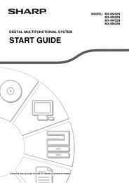
Legend<br />
A = Built-in frame (complete)<br />
B = Microwave oven<br />
C = Ventilation gap<br />
D = Back panel<br />
E = Fastening screw<br />
1 = Spacing bracket 2 pieces<br />
2 = Exhaust duct 1 piece<br />
3 = Exhaust duct 1 piece<br />
4 = Intake duct 1 piece<br />
5 = Intake duct 1 piece<br />
6 = Cushion (490 mm x 15 mm) 1 piece<br />
7 = Cushion (400 mm x 14 mm) 1 piece<br />
8 = Cushion (990 mm x 15 mm) 1 piece<br />
9 = Cushion (580 mm x 66 mm) 1 piece<br />
0 = Built-in frame top element 2 pieces<br />
A = Built-in frame side element 2 pieces<br />
B = Fastening screw (middle) 6 pieces<br />
C = Fastening screw (short)<br />
4 pieces<br />
D = Fastening screw (long)<br />
4 pieces<br />
D<br />
Zeichenerklärung<br />
A = Einbaurahmen, komplett<br />
B = Mikrowellengerät<br />
C = Belüftungsabstand<br />
D = Rückwärtige Wand<br />
E = Befestigungsschraube<br />
1 = Abstandhalter 2 Stck.<br />
2 = Entlüftungskanal 1 Stck.<br />
3 = Entlüftungskanal 1 Stck.<br />
4 = Ansaugkanal 1 Stck.<br />
5 = Ansaugkanal 1 Stck.<br />
6 = Schaumstoffteil (490 mm x 15 mm) 1 Stck.<br />
7 = Schaumstoffteil (400 mm x 14 mm) 1 Stck.<br />
8 = Schaumstoffteil (990 mm x 15 mm) 1 Stck.<br />
9 = Schaumstoffteil (580 mm x 66 mm) 1 Stck.<br />
0 = Einbaurahmen-Oberteil 2 Stck.<br />
A = Einbaurahmen-Seitenteile 2 Stck.<br />
B = Befestigungsschrauben (mittellang) 6 Stck.<br />
C = Befestigungsschrauben (kurz) 4 Stck.<br />
D = Befestigungsschrauben (lang) 4 Stck.<br />
ENGLISH<br />
DEUTSCH<br />
F<br />
Légende<br />
A = Cadre intégré (complet)<br />
B = Four à micro-ondes<br />
C = Ouverture d'aération<br />
D = Panneau arrière<br />
E = Vis de fixation<br />
1 = Entretoise 2 pièces<br />
2 = Conduit d'évacuation 1 pièce<br />
3 = Conduit d'évacuation 1 pièce<br />
4 = Conduit d'aspiration 1 pièce<br />
5 = Conduit d'aspiration 1 pièce<br />
6 = Support (490 mm x 15 mm) 1 pièce<br />
7 = Support (400 mm x 14 mm) 1 pièce<br />
8 = Support (990 mm x 15 mm) 1 pièce<br />
9 = Support (580 mm x 66 mm) 1 pièce<br />
0 = Elément supérieur de cadre intégré 2 pièces<br />
A = Eléments latéraux de cadre intégré 2 pièces<br />
B = Vis de fixation (moyenne) 6 pièces<br />
C = Vis de fixation (courte)<br />
4 pièces<br />
D = Vis de fixation (longue)<br />
4 pièces<br />
NL<br />
Verklaring<br />
A = Inbouwframe (geheel)<br />
B = Magnetronoven<br />
C = Ventilatie-opening<br />
D = Achterpaneel<br />
E = Bevestigingsschroef<br />
1 = Afstandsbeugel 2 stuks<br />
2 = Uitlaatkanaal 1 stuk<br />
3 = Uitlaatkanaal 1 stuk<br />
4 = Inlaatkanaal 1 stuk<br />
5 = Inlaatkanaal 1 stuk<br />
6 = Kussen (490 mm x 15 mm) 1 stuk<br />
7 = Kussen (400 mm x 14 mm) 1 stuk<br />
8 = Kussen (990 mm x 15 mm) 1 stuk<br />
9 = Kussen (580 mm x 66 mm) 1 stuk<br />
0 = Inbouwframe bovenelement 2 stuks<br />
A = Inbouwframe zij-element 2 stuks<br />
B = Bevestigingsschroef (midden) 6 stuks<br />
C = Bevestigingsschroef (kort) 4 stuks<br />
D = Bevestigingsschroef (lang) 4 stuks<br />
NEDERLANDS FRANÇAIS<br />
I<br />
Nome delle parti<br />
A = Telaio incorporato (completo)<br />
B = Forno a microonde<br />
C = Apertura di ventilazione<br />
D = Pannello posteriore<br />
E = Vite di fissaggio<br />
1 = Staffa distanziale 2 pezzi<br />
2 = Condotto di scarico 1 pezzo<br />
3 = Condotto di scarico 1 pezzo<br />
4 = Condotto di aspirazione 1 pezzo<br />
5 = Condotto di aspirazione 1 pezzo<br />
6 = Cuscinetto (490 mm x 15 mm) 1 pezzo<br />
7 = Cuscinetto (400 mm x 14 mm) 1 pezzo<br />
8 = Cuscinetto (990 mm x 15 mm) 1 pezzo<br />
9 = Cuscinetto (580 mm x 66 mm) 1 pezzo<br />
0 = Elemento superiore telaio incorporato 2 pezzi<br />
A = Elementi laterali telaio incorporato 2 pezzi<br />
B = Vite di fissaggio (media) 6 pezzi<br />
C = Vite di fissaggio (corta)<br />
4 pezzi<br />
D = Vite di fissaggio (lungha) 4 pezzi<br />
E<br />
Leyenda<br />
A = Bastidor incorporado (completo)<br />
B = Horno de microondas<br />
C = Orificio de ventilación<br />
D = Panel posterior<br />
E = Tornillos de fijación<br />
1 = Ménsula de espaciamiento 2 piezas<br />
2 = Conducto de escape 1 pieza<br />
3 = Conducto de escape 1 pieza<br />
4 = Conducto de admisión 1 pieza<br />
5 = Conducto de admisión 1 pieza<br />
6 = Almohadilla (490 mm x 15 mm) 1 pieza<br />
7 = Almohadilla (400 mm x 14 mm) 1 pieza<br />
8 = Almohadilla (990 mm x 15 mm) 1 pieza<br />
9 = Almohadilla (580 mm x 66 mm) 1 pieza<br />
0 = Elemento de la parte superior<br />
del bastidor incorporado<br />
2 piezas<br />
A = Elementos laterales del bastidor<br />
incorporado<br />
2 piezas<br />
B = Tornillos de fijación (medianos) 6 piezas<br />
C = Tornillos de fijación (cortos) 4 piezas<br />
D = Tornillos de fijación (largos) 4 piezas<br />
ESPAÑOL<br />
ITALIANO<br />
15
SVENSKA<br />
OBSERVERA - Vid fast installering måste en allpolig brytare (min 3 mm brytavstånd) finnas mellan ugn och<br />
nätet. Brytare vid säkringarna t ex. (Gäller ej i Storbritannien.)<br />
NORSK<br />
ADVARSEL<br />
SUOMI<br />
CAUTION<br />
DANSK<br />
ADVARSEL<br />
- Kun til bruk på fastlandet, med unntak av Storbritannia. Ved hjemmeinnstallering er det<br />
nødvendig med en mangespolet bryter (med kontaktavstand på mer enn 3 mm), til å kople<br />
ovnen fra strømkilden. Eks. overbelastningsbryter for sikring.<br />
- Kotiasennuksessa on oltava kaksinapainen katkaisin (katkojan kärkiväli yli 3 mm), jonka<br />
avulla uuni kytketään irti virtalähteestä. (Esim. varokkeen kytkin.).<br />
- Kun til kontinentalt brug undtagen U.K. Hvis apparatet skal bruges hjemme, skal der bruges<br />
en hel-pols afbryder (med en afstand på mere end 3 mm) fro at afbryde ovne fra<br />
strømtilføuirslen. Ex. afbryder til sikring.<br />
SHARP CORPORATION Osaka, Japan<br />
Recycled paper / Printed with soy ink Printed in Japan<br />
Recyclingpapier / Gedruckt mit Sojafarbe Gedruckt in Japan<br />
Papier recyclé / Imprimé avec de l'encre de soja Imprimé au Japon<br />
Kringlooppapier / Geprint met soja-inkt Gedrukt in Japan<br />
Carta riciclata / Stampato con inchiostro di soia Stampato in Giappone<br />
Papel reciclado / Impreso con tinta de soja Impreso en Japón<br />
16<br />
TINS-A706WRRZ-K61