BD 900 - Haag-Streit USA
BD 900 - Haag-Streit USA
BD 900 - Haag-Streit USA

Create successful ePaper yourself
Turn your PDF publications into a flip-book with our unique Google optimized e-Paper software.
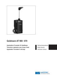
<strong>BD</strong> <strong>900</strong> ®<br />
Spaltlampe<br />
Lampe à fente<br />
Slit lamp<br />
Gebrauchsanweisung<br />
Mode d'emploi<br />
Instruction manual<br />
1<br />
1500.7200631.04040<br />
© <strong>Haag</strong>-<strong>Streit</strong> AG, CH-3098 Koeniz, Switzerland
Vorwort<br />
Wir danken Ihnen, dass Sie sich für ein <strong>Haag</strong>-<strong>Streit</strong> Gerät<br />
entschieden haben.<br />
Bei sorgfältiger Einhaltung der Vorschriften in dieser Gebrauchsanweisung<br />
können wir Ihnen eine zuverlässige und problemlose<br />
Anwendung unseres Produktes gewährleisten.<br />
Die Spaltlampe <strong>BD</strong> <strong>900</strong> ® darf nur von ausreichend qualifiziertem<br />
und autorisiertem Personal benutzt werden.<br />
Werden Änderungen am Gerät vorgenommen oder wird die<br />
Routinewartung gemäß den von der Lieferfirma erteilten<br />
Anweisungen nicht oder mangelhaft durchgeführt, sind wir<br />
gezwungen, sämtliche Garantieleistungen auszuschliessen<br />
und jegliche Haftung abzulehnen.<br />
Es dürfen nur original <strong>Haag</strong>-<strong>Streit</strong> Ersatzteile verwendet werden,<br />
um einen weiterhin zuverlässigen Betrieb des Gerätes<br />
zu gewährleisten.<br />
Avant-propos<br />
Nous vous remercions d’avoir choisi un produit <strong>Haag</strong>-<strong>Streit</strong>.<br />
Si les instructions dans le présent mode d’emploi sont strictement<br />
observées, nous pouvons vous assurer que l’utilisation<br />
de cet instrument ne vous causera aucun problème.<br />
La lampe à fente <strong>BD</strong> <strong>900</strong> ® doit exclusivement être manipulée<br />
par des personnes spécialement formées et autorisées à<br />
manier l’appareil.<br />
Nous serons contraints de refuser toute garantie et de décliner<br />
toute responsabilité dans le cas où l’instrument aura été<br />
modifié d’aucune manière ou si l’entretien périodique aura été<br />
négligé ou réalisé de manière autre que suivant les indications<br />
du constructeur.<br />
Afin d’assurer la fiabilité continue de l’appareil, seules les pièces<br />
de rechange <strong>Haag</strong>-<strong>Streit</strong> devront être utilisées.<br />
Zweckbestimmung<br />
Die Spaltlampe <strong>BD</strong> <strong>900</strong> ® dient der Untersuchung und Diagnose<br />
am menschlichen Auge. Sie wird hauptsächlich in Arztpraxen,<br />
Spitälern und Universitäten bei normalen Umgebungsbedingungen<br />
eingesetzt. Zu den Anwendern gehören Ophthalmologen,<br />
Optometristen und Optiker.<br />
Objectif d'usage<br />
La lampe à fente <strong>BD</strong> <strong>900</strong> ® sert à examiner et faire des<br />
diagnostics de l'oeil humain. Elle est utilisée essentiellement<br />
dans les cabinets de médecin, dans les hôpitaux et dans les<br />
universités sous des conditions normales. Elle est utilisée par<br />
des ophtalmologues, des optométristes et des opticiens.<br />
2<br />
© <strong>Haag</strong>-<strong>Streit</strong> AG, CH-3098 Koeniz, Switzerland 1500.7200631.04040
Introduction<br />
We would like to thank you for your decision to purchase this<br />
<strong>Haag</strong>-<strong>Streit</strong> product.<br />
If the instructions in this manual are carefully followed we are<br />
confident that this product will give you reliable and troublefree<br />
usage.<br />
Only properly trained and authorized persons are to operate<br />
the Slit Lamp <strong>BD</strong> <strong>900</strong> ® .<br />
We will be forced to disclaim any warranty and liability if the<br />
instrument is altered in any way or if routine maintenance is neglected<br />
or not carried out according to factory specifications.<br />
Only original <strong>Haag</strong>-<strong>Streit</strong> spare parts are to be used to ensure<br />
continued reliability of the instrument.<br />
Purpose of use<br />
The Slit Lamp <strong>BD</strong> <strong>900</strong> ® is used, at room temperature, in the<br />
examination, diagnosis and documentation of the human<br />
eye. It is usually used by Ophthalmologists, Optometrists<br />
or Opticians in their consulting rooms, clinics, hospitals or<br />
teaching facilities.<br />
3<br />
1500.7200631.04040<br />
© <strong>Haag</strong>-<strong>Streit</strong> AG, CH-3098 Koeniz, Switzerland
4<br />
Inhaltsverzeichnis<br />
Kurzanleitung. . . . . . . . . . . . . . . . . . . . . . . .Seite 6<br />
1 Übersicht<br />
1.1 Kopfhalter . . . . . . . . . . . . . . . . . . . . . . . . . . . . . . 8<br />
1.2 Spaltlampe <strong>BD</strong> <strong>900</strong> ® . . . . . . . . . . . . . . . . . . . . . . 8<br />
2 Sicherheit . . . . . . . . . . . . . . . . . . . . . . . . . . . . . 10<br />
3 Gerätebeschreibung<br />
3.1 Beleuchtungseinrichtung . . . . . . . . . . . . . . . . . . 10<br />
3.2 Stereomikroskop . . . . . . . . . . . . . . . . . . . . . . . . 14<br />
3.3 Zubehör . . . . . . . . . . . . . . . . . . . . . . . . . . . . . . . 16<br />
3.4 Gerätenetzteil . . . . . . . . . . . . . . . . . . . . . . . . . . 18<br />
3.5 Verstellbare Fixierlampe . . . . . . . . . . . . . . . . . . 20<br />
3.6 Videoausrüstung (Option) . . . . . . . . . . . . . . . . . 20<br />
4 Gerätebedienung<br />
4.1 Beleuchtungseinrichtung . . . . . . . . . . . . . . . . . . 22<br />
4.2 Einstellung der Okulare und der<br />
Augenmuscheln . . . . . . . . . . . . . . . . . . . . . . . . . 24<br />
4.3 Möglichkeiten der Helligkeitsregulierung . . . . . . 24<br />
4.4 Scharfstellen mit Video . . . . . . . . . . . . . . . . . . . 24<br />
Anhang A Gerätemontage<br />
A.1 Anschliessen des Kopfhalters und des<br />
Gerätenetzteils an den HSM-801 oder -901 . . 26<br />
A.2 Anschliessen des Kopfhalters und des<br />
Gerätenetzteils an Fremdtische und Units . . . 26<br />
A.3 Montage der Umfeldbeleuchtung. . . . . . . . . . . . 28<br />
A.4 Montage Kamerakabel . . . . . . . . . . . . . . . . . . . 32<br />
A.5 Montage einer Videokamera<br />
mit Anschluss C-mount . . . . . . . . . . . . . . . . . . 32<br />
A.6 Handhabung der Spaltlampe mit<br />
Videoausrüstung. . . . . . . . . . . . . . . . . . . . . . . 32<br />
A.7 Montage einer Videokamera<br />
mit Anschluss Lipstick. . . . . . . . . . . . . . . . . . . 34<br />
A.8 Montage von Kopfhalter und Gerätenetzteil . . . 34<br />
Anhang B Gerätewartung<br />
B.1 Auswechseln der Halogenlampe . . . . . . . . . . . . 36<br />
B.2 Auswechseln des Beleuchtungsspiegels. . . . . . 38<br />
B.3 Reinigen der Gleitplatte<br />
und der Zahnschienen . . . . . . . . . . . . . . . . . . 38<br />
B.4 Reinigen der Optik . . . . . . . . . . . . . . . . . . . . . . . 38<br />
B.5 Rollachse reinigen . . . . . . . . . . . . . . . . . . . . . . . 38<br />
B.6 Staubhülle . . . . . . . . . . . . . . . . . . . . . . . . . . . . . 38<br />
Anhang C Technische Daten . . . . . . . . . . . . . . . . . 40<br />
Table des matières<br />
Généralités . . . . . . . . . . . . . . . . . . . . . . . . . page 6<br />
1 Nomenclature<br />
1.1 Appui-tête . . . . . . . . . . . . . . . . . . . . . . . . . . . . . . 8<br />
1.2 Lampe à fente <strong>BD</strong> <strong>900</strong> ® . . . . . . . . . . . . . . . . . . . . 8<br />
2 Sécurité. . . . . . . . . . . . . . . . . . . . . . . . . . . . . . . 10<br />
3 Description de l'appareil<br />
3.1 Dispositif d'éclairage . . . . . . . . . . . . . . . . . . . . . 14<br />
3.2 Microscope stéréoscopique . . . . . . . . . . . . . . . . 14<br />
3.3 Accessoires . . . . . . . . . . . . . . . . . . . . . . . . . . . . 16<br />
3.4 Alimentation secteur . . . . . . . . . . . . . . . . . . . . . 18<br />
3.5 Point de fixation réglable . . . . . . . . . . . . . . . . . . 20<br />
3.6 Equipement vidéo (option). . . . . . . . . . . . . . . . . 20<br />
4 Utilisation de l'appareil<br />
4.1 Dispositif d'éclairage . . . . . . . . . . . . . . . . . . . . . 22<br />
4.2 Réglage des oculaires et<br />
des bonnettes . . . . . . . . . . . . . . . . . . . . . . . . . 24<br />
4.3 Possibilités de réglage de la luminosité. . . . . . . 24<br />
4.4 Réglage de la netteté avec le vidéo. . . . . . . . . . 24<br />
Annexe A Montage de l'appareil<br />
A.1 Raccordement d'appui-tête et de l'alimentation<br />
secteur à la table HSM-801 ou -901. . . . . . . . . . 26<br />
A.2 Racc. de l'appui-tête et de l'alim. secteur<br />
à des tables et unités de source étrangère . . . . 26<br />
A.3 Montage de l'eclairage d'ambiance . . . . . . . . . . 28<br />
A.4 Montage des câbles de la caméra. . . . . . . . . . . 32<br />
A.5 Montage de la caméra vidéo<br />
avec raccord monture C . . . . . . . . . . . . . . . . . 32<br />
A.6 Manipulation de la lampe à fente<br />
avec l’équipement vidéo . . . . . . . . . . . . . . . . . 32<br />
A.7 Montage de la caméra vidéo<br />
avec raccord mini caméra. . . . . . . . . . . . . . . . 34<br />
A.8 Montage de l'appui-tête et de l'alim. secteur . . . . .34<br />
Annexe B Entretien de l'appareil<br />
B.1 Remplacement de la lampe halogène . . . . . . . . 36<br />
B.2 Remplacement du miroir . . . . . . . . . . . . . . . . . . 38<br />
B.3 Nettoyage de la plaque de glissement<br />
et des rails dentés. . . . . . . . . . . . . . . . . . . . . . 38<br />
B.4 Nettoyage de l'optique . . . . . . . . . . . . . . . . . . . . 38<br />
B.5 Nettoyage de l'axe . . . . . . . . . . . . . . . . . . . . . . . 38<br />
B.6 Housse en plastique . . . . . . . . . . . . . . . . . . . . . 38<br />
Annexe C Caractéristiques techniques . . . . . . . . 40<br />
© <strong>Haag</strong>-<strong>Streit</strong> AG, CH-3098 Koeniz, Switzerland 1500.7200631.04040
Contents<br />
Summary operating instruction . . . . . . . . . . page 7<br />
1 Overview<br />
1.1 Headrest . . . . . . . . . . . . . . . . . . . . . . . . . . . . . . . 9<br />
1.2 Slit lamp <strong>BD</strong> <strong>900</strong> ® . . . . . . . . . . . . . . . . . . . . . . . . 9<br />
2 Operating safety . . . . . . . . . . . . . . . . . . . . . . . 11<br />
3 Description of the equipment<br />
3.1 Illumination unit . . . . . . . . . . . . . . . . . . . . . . . . . 15<br />
3.2 Stereomicroscope . . . . . . . . . . . . . . . . . . . . . . . 15<br />
3.3 Accessories . . . . . . . . . . . . . . . . . . . . . . . . . . . . 16<br />
3.4 Power supply . . . . . . . . . . . . . . . . . . . . . . . . . . . 19<br />
3.5 Adjustable focusing target . . . . . . . . . . . . . . . . . 21<br />
3.6 Video equipment (option). . . . . . . . . . . . . . . . . . 21<br />
4 Operating the equipment<br />
4.1 Illumination unit . . . . . . . . . . . . . . . . . . . . . . . . . 23<br />
4.2 Adjusting the eye-pieces and the<br />
eyeguards . . . . . . . . . . . . . . . . . . . . . . . . . . . . 25<br />
4.3 Possibilities for regulating the brightness . . . . . 25<br />
4.4 Focussing with the video . . . . . . . . . . . . . . . . . . 25<br />
Appendix A Installation of the equipment<br />
A.1 Attaching the headrest and the power supply<br />
to the instrument table HSM-801 or -901 . . . . 27<br />
A.2 Attaching the headrest and the power supply<br />
to tables and units of other manufacturers . . . 27<br />
A.3 Installation of background illumination. . . . . . . . 29<br />
A.4 Installation of camera cables . . . . . . . . . . . . . . . 33<br />
A.5 Installation of video camera<br />
with C-mount interface . . . . . . . . . . . . . . . . . . 33<br />
A.6 Handling the slit lamp when fitted with<br />
video equipment . . . . . . . . . . . . . . . . . . . . . . . 33<br />
A.7 Installation of video camera<br />
with Lipstick interface . . . . . . . . . . . . . . . . . . . 35<br />
A.8 Mounting of headrest and power supply . . . . . . 35<br />
5<br />
Appendix B Equipment maintenance routines<br />
B.1 Replacement of the halogen bulb . . . . . . . . . . . 37<br />
B.2 Replacement of the mirror . . . . . . . . . . . . . . . . . 39<br />
B.3 Cleaning of the gliding plate<br />
and the rails . . . . . . . . . . . . . . . . . . . . . . . . . . 39<br />
B.4 Cleaning of the optical parts . . . . . . . . . . . . . . . 39<br />
B.5 Cleaning of the axle . . . . . . . . . . . . . . . . . . . . . . 39<br />
B.6 Plastic dust cover. . . . . . . . . . . . . . . . . . . . . . . . 39<br />
Appendix C Technical specifications . . . . . . . . . . 41<br />
1500.7200631.04040<br />
© <strong>Haag</strong>-<strong>Streit</strong> AG, CH-3098 Koeniz, Switzerland
6<br />
Kurzanleitung<br />
1. Mit der Drehschraube (7) die Kinnstütze (6) so einstellen,<br />
dass sich die Augen des Patienten auf der Höhe der seitlich am<br />
Kopfhalter angebrachten schwarzen Marken (4) befinden.<br />
2. Okular-Feststellschraube (25) anziehen. Okulare entsprechend<br />
der Refraktion des Untersuchers durch Drehen an<br />
den gerändelten Ringen fokussieren und den Augenabstand<br />
einstellen.<br />
3. Beleuchtung durch den grünen Hauptschalter am Gerätenetzteil<br />
einschalten.<br />
4. Mit dem Potentiometer (18) kann die Helligkeit kontinuierlich<br />
verstellt werden.<br />
5. Spaltlampe durch Drehen des Lenkhebels (31) in der Höhe<br />
verstellen, bis sich das Lichtbündel auf Augenhöhe befindet.<br />
6. Mit dem leicht gegen den Untersucher geneigten starr geführten<br />
Lenkhebel (31) verschiebt man das ganze Instrument,<br />
bis der Spalt annähernd scharf auf der Hornhaut abgebildet<br />
erscheint. Die Überprüfung dieser groben Einstellung erfolgt<br />
von blossem Auge. Feineinstellungen erreicht man durch<br />
Kippen des am oberen Ende leicht geführten Lenkhebels unter<br />
Beobachtung durch das Stereomikroskop (24).<br />
7. Die Spaltbreite wird links oder rechts mit dem Drehknopf<br />
(17) eingestellt, ebenso der Winkel zwischen Stereomikroskop<br />
und Beleuchtung.<br />
8. Das Spaltbild kann durch Drehen der Beleuchtungseinrichtung<br />
vertikal, horizontal oder beliebig schräg gestellt werden<br />
(Raster bei 90°; Anschläge bei 0° und 180°). Winkelablesung<br />
an der Skala (11).<br />
9. Die Vergrösserung des Stereomikroskops wird bei der<br />
Spaltlampe <strong>BD</strong> <strong>900</strong> ® durch den Wechsel der Objektive mit<br />
dem Hebel (26) oder durch den Austausch der Okulare (Option)<br />
geändert.<br />
10. Zur Übersichtsbeobachtung wird das Graufilter durch den<br />
Hebel (9) vorgeschaltet und die Spaltblende voll geöffnet.<br />
11. Zur Dokumentation kann der Videoausgang (14) benutzt<br />
werden.<br />
12. Zur Fluobilddarstellung lässt sich das Gelbfilter (22) einschwenken.<br />
Généralités<br />
1. Ajustez la mentonnière (6) à l'aide de la vis (7) de manière à<br />
ce que les yeux du patient se trouvent au niveau de la marque<br />
noire (4) située à côté de l'appui-tête.<br />
2. Tirez la vis de réglage de l'oculaire (25). Ajustez le foyer des<br />
oculaires en tournant les anneaux à vrilles selon la réfraction<br />
de l'examinateur et ajustez la distance des yeux.<br />
3. Allumez l'éclairage par l'interrupteur principal de couleur<br />
verte se trouvant sur le bloc d'alimentation.<br />
4. Le potentiomètre (18) permet de régler la luminosité en<br />
continu.<br />
5. Ajustez la lampe à fente verticalement en tournant le levier<br />
(31) jusqu'à ce que le faisceau de lumière se trouve au niveau<br />
des yeux.<br />
6. Déplacez tout l'instrument à l'aide du levier (31) rigide qui<br />
est incliné vers l'examinateur jusqu'à ce que la fente apparaisse<br />
de manière nette sur la cornée. Vous pouvez vérifier<br />
ce réglage préalable à l'oeil nu. Inclinez le bout supérieur du<br />
levier pour effectuer le réglage fin et observez les effets au<br />
microscope (24).<br />
7. Vous pouvez régler la largeur de la fente vers la droite ou<br />
vers la gauche avec le bouton (17) ainsi que l'angle entre le<br />
microscope stéréoscopique et l'éclairage.<br />
8. Vous pouvez mettre l'image de la fente en position verticale,<br />
horizontale ou dans n'importe quelle position intermédiaire<br />
(cran à 90°; butée à 0° et 180°) en tournant le dispositif<br />
d'éclairage. Lecture angulaire sur l'échelle (11).<br />
9. Quant à la lampe à fente <strong>BD</strong> <strong>900</strong> ® le grossissement du<br />
microscope est modifié par le changement de l'objectif au<br />
moyen du levier (26) ou par l'échange de l'oculaire.<br />
10. Pour faire des observations d'ensemble, activez le filtre gris<br />
avec le levier (9) et ouvrez le diaphragme complètement.<br />
11. La sortie vidéo (14) peut être utilisée pour la documentation.<br />
12. Le filtre jaune (22) peut être pivoté pour une représentation<br />
en image fluo.<br />
© <strong>Haag</strong>-<strong>Streit</strong> AG, CH-3098 Koeniz, Switzerland 1500.7200631.04040
Summary operating instructions<br />
1. Move the chinrest (6) up or down with the adjustment screw<br />
(7) until the eyes of the patient are level with the black mark<br />
on the headrest column (4).<br />
2. Tighten the fixing screw of the eye-piece (25). Focus the<br />
eye-pieces to suit your refraction by turning the knurled rings<br />
and then set to your interpupillary distance.<br />
3. Turn on illumination with the green toggle-switch on the<br />
power supply.<br />
4. The brightness can be progressively set and adjusted by<br />
means of the potentiometer (18).<br />
5. Rotate the control lever (31) until the light beam is at eye<br />
level.<br />
6. Holding the control lever (31), inclined towards yourself, move<br />
the instrument base until the slit appears to be approximately<br />
in focus on the cornea. This coarse setting is achieved with<br />
the naked eye. Fine adjustments are obtained by rotating<br />
and tilting the lever while observing the image through the<br />
microscope (24).<br />
7. The slit width is adjusted to the left or right by means of the<br />
knob (17), which also adjusts the angle between the microscope<br />
and the illumination unit.<br />
8. The slit image can be shown in the vertical, horizontal or<br />
slanted positions, as required, by turning the illumination unit<br />
(lock engagement at 90°; stop engagements at 0° and 180°).<br />
The number of degrees can be read-off on the scale (11).<br />
4<br />
6<br />
7<br />
9<br />
11<br />
22<br />
24<br />
25<br />
26<br />
14<br />
17<br />
18<br />
9. The magnification of the microscope in the Slit Lamp <strong>BD</strong><br />
<strong>900</strong> ® is altered by changing the lens with the lever (26) or by<br />
exchanging the eye-pieces.<br />
10. For general observations over a wide field the grey filter<br />
is placed in position by means of lever (9), and the slit is<br />
opened wide.<br />
11. The video output facility (14) can be used for documentation.<br />
12. The contrast enhancing filter, yellow (22) can be engaged<br />
to obtain the fluo-image display.<br />
31<br />
7<br />
1500.7200631.04040<br />
© <strong>Haag</strong>-<strong>Streit</strong> AG, CH-3098 Koeniz, Switzerland
1 Übersicht<br />
1 Nomenclature<br />
1 Overview<br />
1.1 Kopfhalter<br />
1.1 Appui-tête<br />
1.1 Headrest<br />
1 Lampenkabel<br />
2 Kopfhalter<br />
3 Stirnband<br />
4 Höhenmarke am Kopfhalter<br />
(Patientenauge)<br />
5 Verstellbare Fixierlampe<br />
6 Kinnstütze<br />
7 Höhenverstellung der Kinnstütze<br />
1 Câble d'alimentation<br />
2 Appui-tête<br />
3 Bandeau appui-front<br />
4 Indicateur de la hauteur des<br />
yeux du patient<br />
5 Point de fixation réglable<br />
6 Appui-menton<br />
7 Réglage de la hauteur<br />
de l'appui-menton<br />
1 Lamp cable<br />
2 Headrest<br />
3 Forehead band<br />
4 Headrest height marker<br />
(patient's eye)<br />
5 Adjustable focusing target<br />
6 Chinrest<br />
7 Chinrest height adjustment<br />
1.2 Spaltlampe <strong>BD</strong> <strong>900</strong> ®<br />
1.2 Lampe à fente <strong>BD</strong> <strong>900</strong> ®<br />
1.2 Slit Lamp <strong>BD</strong> <strong>900</strong> ®<br />
8<br />
8 Lampendeckel<br />
9 Hebel für Filter Grau und Rotfrei<br />
10 Hebel für Spaltlänge, Blaufilter<br />
11 Skala für Winkellage der<br />
Spaltabbildung<br />
12 Beleuchtungsspiegel<br />
13 Streuscheibe<br />
14 Videoanschluss (C-mount)<br />
15 Schutzdeckel<br />
16 Winkelskala zwischen Beleuchtung<br />
und Stereomikroskop<br />
17 Rändelknopf zum Einstellen der<br />
Spaltbreite<br />
18 Helligkeitseinstellung<br />
19 Anschluss Gerätenetzteil<br />
20 Geschütztes Markenzeichen<br />
<strong>BD</strong> <strong>900</strong> ®<br />
21 Skala für Spaltlänge und Blaufilter<br />
22 Gelbfilter<br />
23 Abdeckkappe der Zubehörauflage<br />
24 Stereomikroskop mit Okularen<br />
25 Okular Feststellschraube<br />
26 Hebel für Objektivwechsel<br />
27 Rändelschraube zur Befestigung<br />
28 Atemschutzschild<br />
29 Schraube zum Blockieren<br />
horizontaler Bewegungen<br />
30 Schienendeckel<br />
31 Lenkhebel<br />
32 Gleitplatte<br />
8 Couvercle du boîtier de la lampe<br />
9 Levier pour les filtres gris et vert<br />
10 Levier pour réglage de la longueur<br />
de fente, filtre bleu<br />
11 Echelle pour la position angulaire<br />
12 Miroir de la lampe<br />
13 Diffuseur<br />
14 Raccordement vidéo (monture C)<br />
15 Couvercle de protection<br />
16 Graduation angulaire entre la<br />
lampe et le microscope<br />
17 Bouton rotatif pour régler la<br />
largeur de la fente<br />
18 Réglage de la luminosité<br />
19 Raccord alimentation secteur<br />
20 Marque déposée <strong>BD</strong> <strong>900</strong> ®<br />
21 Echelle pour la longueur<br />
de la fente et filtre bleu<br />
22 Filtre jaune<br />
23 Câche protecteur<br />
24 Microscope stéréoscopique avec<br />
oculaires<br />
25 Vis de réglage de l'oculaire<br />
26 Levier pour changement de<br />
l’objectif<br />
27 Vis moletée pour la fixation<br />
28 Plaque de protection hygiénique<br />
29 Vis pour bloquer les mouvements<br />
horizontaux<br />
30 Cache-rail<br />
31 Palonnier<br />
32 Plaque de glissement<br />
8 Lamp cover<br />
9 Lever for filter grey and redfree<br />
10 Lever for slit length, blue filter<br />
11 Scale for angled position<br />
of the slit image<br />
12 Interchangeable illumination mirror<br />
13 Diffusor<br />
14 Video connection (C-mount)<br />
15 Protective cover<br />
16 Illumination unit / microscope<br />
angle scale<br />
17 Slit width control<br />
18 Brightness control<br />
19 Plug for power supply<br />
20 Registered trade mark <strong>BD</strong> <strong>900</strong> ®<br />
21 Slit diaphragm scale and blue filter<br />
22 Yellow filter<br />
23 Cap for accessories base<br />
24 Stereo microscope with<br />
eye-pieces<br />
25 Fixing screw of the eye-piece<br />
26 Lens-changing lever<br />
27 Knurled screw for fixation of<br />
28 Breath shield<br />
29 Joy stick base locking screw<br />
30 Rail covers<br />
31 Control lever<br />
32 Gliding plate<br />
© <strong>Haag</strong>-<strong>Streit</strong> AG, CH-3098 Koeniz, Switzerland 1500.7200631.04040
Kopfhalter / Appui-tête / Headrest<br />
Spaltlampe / Lampe à fente / Slit Lamp<br />
1<br />
2<br />
8<br />
3<br />
4<br />
5<br />
6<br />
9<br />
10<br />
11<br />
12<br />
13<br />
20<br />
21<br />
22<br />
23<br />
24<br />
25<br />
7<br />
14<br />
15<br />
26<br />
27<br />
16<br />
17<br />
18<br />
19<br />
28<br />
29<br />
30<br />
31<br />
9<br />
32<br />
1500.7200631.04040<br />
© <strong>Haag</strong>-<strong>Streit</strong> AG, CH-3098 Koeniz, Switzerland
10<br />
2 Sicherheit<br />
Umweltbedingungen<br />
• Transport Temperatur -40 °C bis +70 °C<br />
Luftdruck 500 hPa bis 1060 hPa<br />
Relative Feuchte 10% bis 95%<br />
• Lagerung Temperatur -10 °C bis +55 °C<br />
Luftdruck 700 hPa bis 1060 hPa<br />
Relative Feuchte 10% bis 95%<br />
• Gebrauch Temperatur +10 °C bis +35 °C<br />
Luftdruck 800 hPa bis 1060 hPa<br />
Relative Feuchte 30% bis 75%<br />
Montage<br />
• Instrument vor dem Auspacken einige Stunden in der Verpackung<br />
belassen (Kondensation).<br />
• Spaltlampe und Kopfhalter müssen auf einer elektrisch isolierten<br />
und feuerfesten Tischplatte montiert sein.<br />
• Die Schienendeckel (30) verhindern ein Kippen der Spaltlampe.<br />
• Prüfen: sitzen die Verbindungsteile des Zubehörs (Schraubverbindungen,<br />
Bajonettverschluss)?<br />
Bedienung, Umgebung<br />
• Bedienung nur durch qualifiziertes und geschultes Personal,<br />
dessen Ausbildung ist Aufgabe des Betreibers.<br />
• Nur <strong>Haag</strong>-<strong>Streit</strong> Zubehör verwenden.<br />
• Nach jedem Betrieb Instrument ausschalten. Bei Verwendung<br />
der Staubschutzhülle: Gefahr durch Überhitzung.<br />
• Mit Okularen niemals in die Sonne blicken.<br />
• Instrument nicht in explosionsgefährdeten Bereichen benutzen,<br />
keine flüchtigen Lösungsmittel (Alkohol, Benzin usw.) und<br />
brennbare Narkosemittel in der Nähe.<br />
• Feuchtigkeit vermeiden.<br />
Lampenwechsel<br />
• Netzschalter ausschalten - Netzstecker ziehen.<br />
• Lampe abkühlen lassen!<br />
• Die Spaltlampe darf nur zum Wechseln der Lampe geöffnet<br />
werden.<br />
Elektrisches<br />
• Nur ein typengeprüftes 3-poliges Netzkabel verwenden.<br />
Für <strong>USA</strong> und Kanada Netzkabelset, nach UL-Liste, Typ SJE,<br />
SJT oder SJO, 3-polig, nicht kleiner als 18 AWG.<br />
• Stecker, Kabel und Schutzleiteranschluss der Steckdose<br />
müssen einwandfrei funktionieren<br />
Reinigung<br />
• Spaltlampengehäuse nur mit leicht angefeuchtetem Tuch<br />
reinigen.<br />
• Keine Flüssigkeiten, keine ätzenden Mittel.<br />
• Nur die Aussenflächen der Optikteile säubern.<br />
Lichttoxizität<br />
• Eine lange und intensive Beleuchtung kann die Retina schädigen.<br />
Die Helligkeitseinstellung sollte daher den Wert nicht<br />
überschreiten, welcher für eine klare Darstellung der Zielstrukturen<br />
benötigt wird. Eine Untersuchung mit diesem Instrument<br />
darf nicht unnötig ausgedehnt werden.<br />
2 Sécurité<br />
Conditions de l'environnement<br />
• Transport Température -40 °C à +70 °C<br />
Pression atmosph. 500 hPa à 1060 hPa<br />
Humidité relative 10% à 95%<br />
• Stockage Température -10 °C à +55 °C<br />
Pression atmosph. 700 hPa à 1060 hPa<br />
Humidité relative 10% à 95%<br />
• Travail Température +10 °C à +35 °C<br />
Pression atmosph. 800 hPa à 1060 hPa<br />
Humidité relative 30% à 75%<br />
Installation<br />
• Afin d'éviter toute condensation, veillez à laisser l'instrument<br />
dans l'emballage pendant plusieurs heures.<br />
• Montez toujours la lampe à fente et l’appui-tête sur un plateau<br />
de table électriquement isolé et résistant au feu.<br />
• Les cache-rails (30) évitent une inclinaison de la lampe à fente.<br />
• Rassurez-vous: les raccords pour les accessoires sont-ils serrés<br />
(par ex. les assemblages par vis et le joint à baïonnette)?<br />
Opération et environnement<br />
• Seul un personnel qualifié et formé a le droit d'utiliser cet instrument,<br />
la formation des opérateurs incombe au propriétaire.<br />
• Utilisez seulement les accessoires <strong>Haag</strong>-<strong>Streit</strong>.<br />
• Eteindre après chaque utilisation. Avec l'utilisation de la housse<br />
en plastique: risque de surchauffe.<br />
• Ne jamais regarder avec l'oculaire dans le plein soleil.<br />
• N’utilisez jamais l’instrument dans des zones où il y a des<br />
gaz explosifs, des vapeurs combustibles (alcool, benzol) ou<br />
des agents anesthésiques inflammables.<br />
• Evitez toute source d'humidité.<br />
Remplacer l'ampoule<br />
• Couper l’interrupteur principal.<br />
• Permettez l’ampoule de refroidir.<br />
• N’ouvrez pas la lampe à fente pour aucune autre raison que<br />
pour remplacer l’ampoule.<br />
Installation électrique<br />
• N'utilisez qu'un câble d'alimentation secteur à trois conducteurs<br />
homologué. Pour <strong>USA</strong> et Canada: Câble d'alimentation<br />
électrique, selon UL, type SJE, SJT ou SJO, tripolaire, plus<br />
grand que 18 AWG.<br />
• Toutes les fiches, les câbles et le conducteur de protection<br />
de la prise doivent être en état parfait.<br />
Nettoyage<br />
• Nettoyez le boîtier de la lampe à fente seulement avec un<br />
linge légèrement humide.<br />
• N’utilisez aucun liquide ni de produits abrasifs.<br />
• Nettoyez uniquement l’extérieur des pièces de l’optique.<br />
Toxicité de lumière<br />
• Un éclairage long et intensif peut endommager la rétine. Le<br />
réglage de la luminosité ne devrait pas dépasser la valeur<br />
qui est nécessaire à une bonne représentation des structures<br />
ciblées. Un examen avec cet instrument ne doit pas être<br />
inutilement prolongé.<br />
© <strong>Haag</strong>-<strong>Streit</strong> AG, CH-3098 Koeniz, Switzerland 1500.7200631.04040
2 Safety<br />
Ambient conditions<br />
• Transportation Temperature -40 °C to +70 °C<br />
Air pressure 500 hPa to 1060 hPa<br />
Relative humidity 10% to 95%<br />
• Storage Temperature -10 °C to +55 °C<br />
Air pressure 700 hPa to 1060 hPa<br />
Relative humidity 10% to 95%<br />
• Working Temperature +10 °C to +35 °C<br />
Air pressure 800 hPa to 1060 hPa<br />
Relative humidity 30% to 75%<br />
Installation<br />
• To avoid condensation, allow the instrument to adjust to room<br />
temperature for several hours before unpacking.<br />
• Always mount the slit lamp and the headrest on an electric<br />
insulated and fire resistant table top.<br />
• The rail covers (30) prevent from a tip over of the slit lamp.<br />
• Check: do the connection pieces of the accessories fit (like<br />
screwed connections and bayonet fitting)?<br />
Operation and surrounding<br />
• Only qualified and trained personnel should operate the equipment,<br />
the training is at the owner’s responsibility.<br />
• Use only <strong>Haag</strong>-<strong>Streit</strong> accessories.<br />
• Shut down after every use. In case the dust cover is used:<br />
risk of overheating.<br />
• Never use the ocular to look at the sun.<br />
• Never operate the instrument in the same room with combustible<br />
gases, volatile solvents (alcohol, benzol) or flammable<br />
anesthetic agents.<br />
• Avoid humidity.<br />
30<br />
Changing the light bulbs<br />
• Switch off the main switch - disconnect the mains connector.<br />
• Allow the bulb to cool down.<br />
• Do not open the slit lamp for any other reason than to change<br />
the light bulb.<br />
11<br />
Electrical<br />
• Only a hospital grade 3-conductor electrical power supply<br />
cable must be used. For <strong>USA</strong> and Canada: Detachable Power<br />
Supply Cord Set, UL Listed, type SJE, SJT or SJO, 3-conductor,<br />
not smaller than 18 AWG.<br />
• Plug, cable and ground lead connection of the socket have<br />
to be in perfect condition.<br />
Cleaning<br />
• Clean the slit lamp housing only with a slightly water dampened<br />
cloth.<br />
• No liquids or corrosive agents.<br />
• Clean only the exterior surfaces of the optical parts.<br />
Light toxicity<br />
• Long and intensive illumination could damage the retina. The<br />
brightness of illumination should be kept at a minimum, to view<br />
the structure of the target clearly. To avoid potential eye damage,<br />
the examination should not last longer than necessary.<br />
Instrumententisch HSM-901 Typ M<br />
Unbedingt diesen Sicherheitshinweis beachten<br />
Table d' instruments HSM-901 type M<br />
Faire attention aux indications de sécurité suivantes<br />
Instrument Table HSM-901 type M<br />
Observe the following safety precautions<br />
Höhenverstellung nur mit aufgesetztem Gerät betätigen<br />
Do not use height adjustment without instrument in place<br />
Ne pas utiliser le réglage en hauteur quand l'instrument n'est pas en place<br />
Patents US Pat. 3.685.779<br />
and other countries<br />
<strong>Haag</strong>-<strong>Streit</strong> BERN<br />
SWISS MADE<br />
1500.7200631.04040<br />
© <strong>Haag</strong>-<strong>Streit</strong> AG, CH-3098 Koeniz, Switzerland
12<br />
• Die retinale Dosis für eine fotochemische Gefährdung setzt<br />
sich aus der Strahldichte und der Bestrahlungszeit zusammen:<br />
Wird die Strahldichte um die Hälfte reduziert, verdoppelt sich die<br />
Zeit, bis der Grenzwert der Bestrahlungszeit erreicht wird.<br />
• Bisher wurde keine akute optische Strahlungsgefährdung bei<br />
Spaltlampen nachgewiesen. Wir empfehlen aber trotzdem, die<br />
Intensität des Lichtes, welches auf die Retina des Patienten<br />
fällt, auf das mögliche Minimum für die jeweilige Diagnose zu<br />
beschränken. Kinder, Aphake und Personen mit erkrankten<br />
Augen sind am meisten gefährdet.<br />
• Erhöhtes Risiko kann auch dann bestehen, wenn die Retina<br />
innerhalb von 24 Stunden dem gleichen oder einem anderen<br />
Instrument mit sichtbarer Lichtquelle ausgesetzt wird.<br />
Dies gilt besonders, wenn die Retina vorher mit einem Blitzlicht<br />
fotografiert wird.<br />
Garantie / Produktehaftpflicht<br />
• Das Produkt ist entsprechend dem Kapitel 'Sicherheit' zu<br />
behandeln. Unsachgemässe Behandlung kann zu Schäden<br />
am Produkt führen. Dadurch erlöschen sämtliche Garantieansprüche.<br />
• Wird ein durch unsachgemässe Behandlung beschädigtes<br />
Produkt weiterhin eingesetzt, kann dies zu Personenschäden<br />
führen. Der Hersteller haftet in diesem Fall nicht.<br />
• Instandsetzungen und Änderungen am Produkt dürfen nur<br />
von <strong>Haag</strong>-<strong>Streit</strong> Servicetechnikern oder von autorisierten Personen<br />
durchgeführt werden.<br />
Gesetzliche Vorschriften<br />
• Die Spaltlampe <strong>BD</strong> <strong>900</strong> ® wurde unter Berücksichtigung der Normen<br />
IEC / EN 60 601-1 und ISO 10939 konstruiert. Unter der<br />
Beachtung schweizerischer und internationaler Auflagen erfolgen<br />
Fertigung, Prüfung, Aufstellung, Wartung und Reparatur.<br />
• Beim Kombinieren verschiedener medizinisch und/oder<br />
nichtmedizinisch elektrischer Geräte ist die Norm IEC / EN<br />
60 601-1 zu berücksichtigen<br />
• Durch die CE-Kennzeichnung wird die Übereinstimmung<br />
der Spaltlampe <strong>BD</strong> <strong>900</strong> ® mit den Richtlinien 93/42/EWG und<br />
89/336/EWG und dem Konformitätsmodul A bestätigt.<br />
• Eine Kopie der Konformitätserklärung und der EMV Hinweise<br />
(Elektromagnetische Verträglichkeit) zum vorliegenden Instrument<br />
kann jederzeit bei <strong>Haag</strong>-<strong>Streit</strong> angefordert werden.<br />
• Die gesetzlichen Unfallverhütungsvorschriften sind zu beachten.<br />
• Klassierung<br />
Norm IEC / EN 60 601-1<br />
CE-Richtlinie 93/42 EWG Klasse I<br />
FDA<br />
Klasse II<br />
Spaltlampe <strong>BD</strong> <strong>900</strong> ® nach<br />
Schutzklasse I<br />
Anwendungsteil Typ B.<br />
Betriebsart: Dauerbetrieb<br />
Piktogramme<br />
a Mit Aufmerksamkeit lesen (in Gebrauchsanweisung)!<br />
b Warnung vor heissen Oberflächen!<br />
c Netzstecker ziehen!<br />
d Schutzklasse II<br />
e Hersteller<br />
f Seriennummer<br />
g HS Bestellnummer<br />
h Produkteklassifikation Typ B<br />
i Herstellungsdatum<br />
• La dose photochimique à risque pour la rétine se compose de<br />
l'intensité de rayonnement et du temps de l'examen: si l'intensité de<br />
rayonnement est réduite de moitié, le temps est multiplié par deux<br />
jusqu'à obtention de la valeur limite du temps d'exposition.<br />
• Jusqu'à présent, il n'a pu être constaté aucun risque d'irradiation<br />
imminent avec les lampes à fente. Nous recommandons cependant<br />
de limiter autant que possible l'intensité lumineuse dirigée<br />
sur la rétine du patient pour effectuer les différents diagnostics.<br />
Les enfants, les personnes aphaques ou aux yeux fragiles sont<br />
les plus exposés.<br />
• Un risque accru peut également exister si la rétine est exposée<br />
dans une période de 24 heures au même instrument ou à<br />
un autre instrument avec une source lumineuse visible. C'est<br />
en particulier le cas si la rétine a été photographiée auparavant<br />
avec flash.<br />
Garantie / responsabilité de produit<br />
• Cet instrument doit être manipulé conformément aux consignes<br />
énoncées au chapitre 'Sécurité'. Une utilisation non<br />
conforme à ces consignes est susceptible d’entraîner des<br />
dommages sur l’instrument. Ainsi le client perd tout bénéfice<br />
de la garantie.<br />
• Si un produit endommagé par une utilisation non conforme<br />
continue à être utilisé, il est susceptible de causer des dommages<br />
aux personnes. Dans ce cas, le fabricant décline toute<br />
responsabilité.<br />
• Seuls les techniciens <strong>Haag</strong>-<strong>Streit</strong> ou des personnes autorisées<br />
ont le droit de réparer ou de modifier l'instrument.<br />
Dispositions légales<br />
• La lampe à fente <strong>BD</strong> <strong>900</strong> ® a été conçue conformément aux<br />
normes IEC / EN 60 601-1 et ISO 10939. La fabrication, le test,<br />
le montage, l’entretien et la réparation doivent être effectués en<br />
respectant les dispositions légales suisses et internationales.<br />
• Lors de combinaison de différents instruments médicaux<br />
et/ou non-médicaux électriques, la norme IEC / EN 60 601-1<br />
doit être observée.<br />
• L’insigne CE indique que la lampe à fente <strong>BD</strong> <strong>900</strong> ® est conforme<br />
aux prescriptions 93/42/CEE et 89/336/CEE et au module<br />
de conformité A.<br />
• Une copie de la déclaration de conformité et des remarques concernant<br />
la CEM (Compatibilité électromagnétique) de cet instrument<br />
peut être demandé à tout instant à l'entreprise <strong>Haag</strong>-<strong>Streit</strong>.<br />
• Les dispositions légales de prévention des accidents doivent<br />
être observées.<br />
• Classification<br />
Norme IEC / EN 60 601-1 Lampe à fente <strong>BD</strong> <strong>900</strong> ® classe de protection<br />
I. Partie d’application type B.<br />
Mode d’exploitation: a longue durée<br />
Directive CE 93/42 CEE Classe I<br />
FDA<br />
Classe II<br />
Pictogrammes<br />
a Lire avec attention (dans le mode d'emploi)!<br />
b Danger de surfaces chaudes!<br />
c Retirez la prise électrique!<br />
d Classe de protection II<br />
e Fabricant<br />
f Numéro de série<br />
g HS numéro de commande<br />
h Classification de produit type B<br />
i Date de fabrication<br />
© <strong>Haag</strong>-<strong>Streit</strong> AG, CH-3098 Koeniz, Switzerland 1500.7200631.04040
• The retinal dose for potential photo chemical damage depends<br />
on ray density and examination time. When the ray<br />
density is cut in half, the examination time doubles until the<br />
border value is reached.<br />
• Until today, there is no proof established that slit lamp examination<br />
can endanger the eye. Nevertheless, we recommend<br />
to use the minimum amount of light possible for retinal<br />
examination.<br />
• Children, Aphakics and people with eye problems are especially<br />
endangered. If the retina is exposed to the same or another<br />
light source in 24 hours, there is also a higher risk. This is<br />
especially true when a retinal picture is taken with flash.<br />
Warranty / product liability<br />
• The instrument should be operated in accordance with the<br />
chapter 'Safety'. Incorrect operation can damage the instrument.<br />
Thus no warranty claims can be accepted.<br />
• Continued use of an instrument that has been damaged by<br />
incorrect operation can lead to personal injury. The manufacturer<br />
cannot accept liability in this case.<br />
• Repairs and alterations on this equipment should only be<br />
carried out by <strong>Haag</strong>-<strong>Streit</strong> service technicians or by authorized<br />
persons.<br />
Statutory requirements<br />
• The slit lamp <strong>BD</strong> <strong>900</strong> ® has been designed to conform with<br />
the IEC / EN 60 601-1 and ISO 10939 standards. Manufacturing<br />
procedures, testing, commissioning, maintenance and<br />
repair are conducted under the observance of Swiss and international<br />
regulations.<br />
• When combining different medical and/or nonmedical electrical<br />
equipment standard IEC / EN 60 601-1 applies.<br />
• The 'CE' marking confirms compliance of the slit lamp <strong>BD</strong> <strong>900</strong> ®<br />
with the directives 93/42/EEC and 89/336/EEC and the conformity<br />
module A.<br />
• A copy of the declaration of conformity and information concerning<br />
EMC (Electromagnetic compatibility) of the present instrument<br />
can be requested at any time at <strong>Haag</strong>-<strong>Streit</strong> company.<br />
• All statutory accident prevention regulations are to be observed.<br />
• Classification<br />
IEC / EN Standard 60 601-1 Slit Lamp <strong>BD</strong> <strong>900</strong> ® equipment<br />
safety class I<br />
Application part Type B<br />
Operation mode: continuous<br />
operation<br />
CE-Regulation 93/42 EEC Class I<br />
FDA<br />
Class II<br />
Umwelt<br />
• Elektro- und Elektronikgeräte müssen getrennt<br />
vom Hausabfall entsorgt werden! Dieses Gerät<br />
wurde nach dem 13.08.2005 in den Handel<br />
gebracht.<br />
• Entsorgung über die lokale Sammelstelle oder<br />
über Ihren <strong>Haag</strong>-<strong>Streit</strong> Vertreter.<br />
• Damit ist gewährleistet, dass keine schädlichen<br />
Stoffe in die Umwelt gelangen und wertvolle Rohstoffe<br />
wieder Verwendung finden.<br />
Environnement<br />
• Les appareils électriques et électroniques ne<br />
doivent pas être jetés avec les déchets de ménage!<br />
Cet appareil a été introduit sur le marché<br />
après le 13.08.2005.<br />
• L‘enlèvement des déchets s‘effectue au point<br />
de ramassage local ou chez votre distributeur<br />
<strong>Haag</strong>-<strong>Streit</strong>.<br />
• Ainsi il est garanti qu‘aucune matière nuisible<br />
n‘arrive dans l‘environnement mais que les matières<br />
premières précieuses soient reutilisées.<br />
Environment<br />
• Electric and electronic equipment must be separated<br />
from house waste! This equipment has<br />
been introduced into the market after the 13th<br />
of August 2005.<br />
• Disposal via your local collecting point or your<br />
<strong>Haag</strong>-<strong>Streit</strong> distributor.<br />
• Thus it is ensured, that no harmful materials<br />
get into the environment and that valuable raw<br />
materials can be used again.<br />
a<br />
b<br />
c<br />
d<br />
13<br />
Pictograms<br />
a Read very carefully (in the instruction manual)!<br />
b Warning for hot surfaces!<br />
c Disconnect the electrical supply plug!<br />
d Safety class II<br />
e Manufacturer<br />
f Serial number<br />
g HS-Part Number<br />
h Type B equipment<br />
i Date of manufacture<br />
1500.7200631.04040<br />
e f g h i<br />
© <strong>Haag</strong>-<strong>Streit</strong> AG, CH-3098 Koeniz, Switzerland
3 Gerätebeschreibung<br />
3.1 Beleuchtungseinrichtung<br />
Halogenlampe<br />
Die Halogenlampe wird im Werk zentriert, um eine optimale<br />
Ausleuchtung zu gewährleisten.<br />
Das ausgestrahlte Licht der vorzentrierten Halogenlampe<br />
passiert Kondensor, Spaltblende und Objektivlinse und wird<br />
über den schräg stehenden Spiegel in das Auge des Patienten<br />
gelenkt.<br />
3 Description de l'appareil<br />
3.1 Dispositif d'éclairage<br />
Lampe halogène<br />
La lampe halogène est centrée en usine pour assurer un<br />
éclairage optimal.<br />
La lumière émise par l'ampoule centrée traverse le condensateur,<br />
le diaphragme et la lentille de l'objectif. Ensuite elle est<br />
déviée par un miroir oblique dans l'oeil du patient.<br />
Im Strahlengang der Beleuchtung befinden sich<br />
Filter Bedienung durch Hebel (34)<br />
36 offen<br />
37 Rotfreifilter<br />
38 Graufilter (10%)<br />
Die Norm ISO 10939 schreibt fest eingebaute Wärmeschutzund<br />
UV-Filter vor!<br />
Dans le faisceau de l'éclairage sont interposés<br />
Filtres maniement par levier (34)<br />
36 Ouvert<br />
37 Filtre vert<br />
38 Filtre gris (10%)<br />
La norme ISO 10939 exige que les filtres anti-calorique et UV<br />
soient montés en permanence!<br />
Blenden im Fenster (33) Bedienung durch Hebel (35)<br />
39 Rundblende von 14 mm ø<br />
40 Keilblende für kontinuierliche Spaltlängenverstellung<br />
41 Blaufilter<br />
Diaphragmes dans la fenêtre (33) maniement par levier (35)<br />
39 Diaphragme circulaire de 14 mm ø<br />
40 Diaphragme progressif pour le réglage<br />
continu de la longueur de la fente<br />
41 Filtre bleu<br />
14<br />
3.2 Stereomikroskop<br />
42 Zwei Objektiv-Linsenpaare<br />
43 Hebel für Gelbfilter<br />
44 Abdeckkappe der Zubehörauflage<br />
45 Seriennummer Mikroskop<br />
46 Okular 10x oder 25x<br />
47 Anschluss für Videokamera (C-mount)<br />
48 Hebel für Objektivwechsel<br />
49 Okular-Feststellschraube<br />
Objektiv 1x 1.6x 1x 1.6x<br />
Okular 10x 10x 25x 25x<br />
Gesamtvergrösserung 10x 16x 25x 40x<br />
Objektfeld ø mm 18 11.3 8 5<br />
3.2 Microscope stéréoscopique<br />
42 Deux lentilles d'objectif<br />
43 Levier pour filtre jaune<br />
44 Cache protecteur<br />
45 Numéro de série du microscope<br />
46 Oculaire 10x ou 25x<br />
47 Raccordement de la caméra vidéo (monture C)<br />
48 Levier de changement de grossissement<br />
49 Vis de réglage de l'oculaire<br />
Objectif 1x 1.6x 1x 1.6x<br />
Oculaire 10x 10x 25x 25x<br />
Grossissement 10x 16x 25x 40x<br />
Champ visuel ø mm 18 11.3 8 5<br />
© <strong>Haag</strong>-<strong>Streit</strong> AG, CH-3098 Koeniz, Switzerland 1500.7200631.04040
3 Description of equipment<br />
3.1 Illumination unit<br />
Halogen bulb<br />
The halogen bulb is centered ex-works to obtain an optimal<br />
illumination.<br />
The light beam from the pre-centered halogen bulb passes<br />
through the condenser, the slit diaphragm and the illumination<br />
lens, before it is directed to the patient's eye by the oblique<br />
mirror.<br />
33<br />
34<br />
35<br />
The following can be mounted in the path of the light beam of<br />
the illumination unit<br />
Filters operating by lever (34)<br />
36 Open aperture<br />
37 Redfree filter<br />
38 Grey filter (10%)<br />
36 37 38<br />
Due to standard ISO 10939 the heat absorption filter and UV<br />
filter are permanently mounted!<br />
Apertures at window (33) operating by lever (35)<br />
39 Aperture producing area of 14 mm ø<br />
40 Wedge-shaped diaphragm for continuous slit<br />
length adjustment<br />
41 Blue filter<br />
39 40 41<br />
3.2 Stereomicroscope<br />
42 Two objective lenses<br />
43 Lever for yellow filter<br />
44 Cap for accessories base<br />
45 Serial number of microscope<br />
46 Eye-piece 10x or 25x<br />
47 Connection for the video camera (C-mount)<br />
48 Lens-changing lever<br />
49 Eye-piece fixing screw<br />
Lens 1x 1.6x 1x 1.6x<br />
Eye-piece 10x 10x 25x 25x<br />
Total magnification 10x 16x 25x 40x<br />
Object image section ø mm 18 11.3 8 5<br />
42 43 44 45 46<br />
15<br />
47 48 49<br />
1500.7200631.04040<br />
© <strong>Haag</strong>-<strong>Streit</strong> AG, CH-3098 Koeniz, Switzerland
3.3 Zubehör zum Basismodell <strong>BD</strong> <strong>900</strong> ®<br />
Accessoires pour le modèle de base <strong>BD</strong> <strong>900</strong> ®<br />
Accessories for standard model <strong>BD</strong> <strong>900</strong> ®<br />
mit <strong>Haag</strong>-<strong>Streit</strong> Bestellnummern<br />
avec numéros de référence <strong>Haag</strong>-<strong>Streit</strong><br />
with <strong>Haag</strong>-<strong>Streit</strong> part numbers<br />
Standard Okular<br />
Oculaire standard<br />
Standard eye-piece<br />
10x 1200671<br />
Halogenlampe mit Flansch<br />
Ampoule halogène avec bride<br />
Halogen bulb with flange<br />
1200559<br />
rot / rouge / red<br />
gelb / jaune / yellow<br />
Identifikationsfarbe<br />
Couleur d'identification<br />
Identification colour<br />
Längenmessokular<br />
Objectif pour mesure de la longueur<br />
Eye-piece for length measurement<br />
10x 1002602<br />
Doppelfadenkreuz-Okular<br />
Objectif avec réticule double<br />
Eye-piece with crosshair-reticule<br />
10x 1003022<br />
Okular<br />
Oculaire<br />
Eye-piece<br />
25x 1200987<br />
OLCR kontaktloses Pachymeter*<br />
OLCR Pachymètre sans contact*<br />
OLCR non contact Pachymeter*<br />
Goldmann Applanations Tonometer<br />
Tonomètre à aplanation d'après Goldmann<br />
Goldmann Applanation Tonometer<br />
AT <strong>900</strong> C/M 7200154<br />
16<br />
Adapter für Lipstick auf C-mount *<br />
Adaptateur pour mini caméra sur monture C *<br />
Adapter for Lipstick on C-mount *<br />
Distanzschraube<br />
Vius de distance<br />
Distance screw<br />
1008363<br />
Justierstab<br />
Tige d'ajustage<br />
Focusing rod<br />
1200782<br />
Aufsteckbasis<br />
Pivot de fixation<br />
Fixation base<br />
1003603<br />
Streuscheibe<br />
Diffuseur<br />
Diffusor<br />
1004744<br />
Spiegel<br />
Miroir<br />
Mirror<br />
1200602<br />
Schutzabdeckung<br />
Couvercle de protection<br />
Protecting cover<br />
1200602<br />
Negatives Vorsatzglas (Hruby)<br />
Lentille intercalaire négative<br />
Minus preset lens<br />
1400223<br />
Führungsplatte<br />
Plaque de guidage<br />
Guide plate<br />
1001219<br />
Vorsatzglaswagen mit Schiene<br />
Chariot pour lentilles intercalaires<br />
Carriage for preset lenses with rail<br />
1400100<br />
© <strong>Haag</strong>-<strong>Streit</strong> AG, CH-3098 Koeniz, Switzerland 1500.7200631.04040
Kopfhalter mit Fixierlampe *<br />
Appui-tête avec lampe de fixation *<br />
Headrest with fixation lamp *<br />
Papierservietten für Kinnstütze<br />
Serviettes papier pour mentonnière<br />
Chinrest papers<br />
1001309<br />
Steckstift zu Kinnstütze<br />
Bouton pour mentonnière<br />
Pin for chinrest<br />
1200713<br />
Instrumententisch HSM-801 *<br />
Table d'instruments HSM-801 *<br />
Instrument table HSM-801 *<br />
Stiftschlüssel<br />
Clé à 6 pans<br />
Allen key<br />
5 mm 1001602<br />
Instrumententisch HSM-901 *<br />
Table d'instruments HSM-901 *<br />
Instrument table HSM-901 *<br />
Gerätenetzteil *<br />
Alimentation secteur *<br />
Power supply *<br />
17<br />
Kaltlichtquelle *<br />
Source de lumière froide *<br />
Cold light source *<br />
Camera Module CM <strong>900</strong>*<br />
(C-mount)<br />
Umfeldbeleuchtung EcoLite EL 02*<br />
Eclairage d’ambiance EcoLite EL 02*<br />
Background illumination EcoLite EL 02*<br />
* für weitere Informationen wenden Sie sich bitte an Ihren <strong>Haag</strong>-<strong>Streit</strong> Händler<br />
* pour de plus amples informations adressez vous à votre distributeur <strong>Haag</strong>-<strong>Streit</strong><br />
* for further information ask your <strong>Haag</strong>-<strong>Streit</strong> distributor<br />
1500.7200631.04040<br />
© <strong>Haag</strong>-<strong>Streit</strong> AG, CH-3098 Koeniz, Switzerland
3.4 Gerätenetzteil<br />
(Typenbezeichnung: LC-SLT)<br />
ACHTUNG<br />
Das Gerätenetzteil ist mit einem Spannungswahlschalter<br />
(50) 115 V / 230 V ausgerüstet.<br />
Der Bereich ist vor der ersten Inbetriebnahme<br />
dem örtlichen Stromnetz entsprechend<br />
einzustellen.<br />
3.4 Alimentation secteur<br />
(dénomination du type: LC-SLT)<br />
ATTENTION<br />
L'alimentation secteur est équipé d'un interrupteur<br />
(50) de sélection de la tension 115 V / 230 V.<br />
Il convient de sélectionner la bonne tension<br />
en foction du réseau local avant la première<br />
mise en service.<br />
18<br />
Der Hauptschalter (52) leuchtet grün, wenn das Gerät eingeschaltet<br />
ist.<br />
Mögliche Fehlerursachen<br />
1. Hauptschalter eingeschaltet, aber er leuchtet nicht:<br />
• Primärsicherungen defekt<br />
2. Hauptschalter leuchtet, aber die Spaltlampe nicht:<br />
• Sekundärsicherung oder Halogenlampe defekt<br />
Auswechseln der Primärsicherung<br />
Mit einem Schraubenzieher Sicherungsfach (53) öffnen.<br />
Defekte Sicherungen wechseln. Sicherungsfach einschieben<br />
bis es hörbar einschnappt.<br />
Sicherung 2 x T 800 mA HS-Part Number 1001330<br />
Auswechseln der Sekundärsicherung<br />
Schlitz des Sicherungshalters (51) mit einem Schraubenzieher<br />
nach links drehen. Sicherung wechseln.<br />
Sicherung F 3.15 A HS-Part Number 1001331<br />
Die Helligkeit wird mit dem Helligkeitsregler (18) eingestellt.<br />
Beleuchtungsstärke siehe unter Anhang C - Technische<br />
Daten.<br />
L'interrupteur principal (52) émet une luimière verte quand<br />
l'appareil est sous tension.<br />
Causes possibles d'erreur<br />
1. L'interrupteur principal est sous tension mais n'émet pas<br />
de lumière:<br />
• fusibles primaires défectueux<br />
2. L'interrupteur principal est lumineux, mais pas la lampe<br />
de fente:<br />
• fusible secondaire ou lampe halogène défectueux<br />
Changement du fusible primaire<br />
Ouvrir le compartiment à fusible (53) à l'aide d'un tournevis.<br />
Remplacer les fusibles défectueux. Insérer le compartiment à<br />
fusible jusqu'à ce qu'un déclic se fasse entendre.<br />
Fusible 2 x T 800 mA HS-Part Number 1001330<br />
Changement du fusible secondaire<br />
Tourner la fente du porte-fusible (51) vers la gauche à l'aide<br />
d'un tournevis. Remplacer le fusible.<br />
Fusible F 3.15 A HS-Part Number 1001331<br />
La luminosité se règle à l'aide du réglage de la luminosité (18).<br />
L'intensité de la lumière: voir annexe C - Caractéristiques<br />
techniques.<br />
3.5 Verstellbare Fixierlampe<br />
Wenn das Lampenkabel (54) angeschlossen ist, brennt die<br />
Fixierlampe sobald der Schalter am Netzteil eingeschaltet<br />
wird, die Fixiermarke (59) ist sichtbar.<br />
Über den Tragarm (55) ist die Fixierlampe in jeder Richtung beweglich.<br />
Für den Untersucher bietet sich damit die Möglichkeit,<br />
dass während der Beobachtung durch das Mikroskop das zu<br />
untersuchende Auge ohne Unterbrechung in die gewünschte<br />
Blickrichtung gebracht werden kann. Für Untersuchungen am<br />
Fundus ist dies ein grosser Vorteil.<br />
Voraussetzung ist, dass das Auge des Patienten genau auf<br />
der Höhe der schwarzen Markierung (58) des Kopfhalters<br />
positioniert wurde.<br />
Eine Fehlsichtigkeit des Patienten von +10 D bis -15 D (56) kann<br />
korrigiert werden (57). Dadurch ist eine sichere Ruhigstellung<br />
der Augen gewährleistet, da Akkommodation und Konvergenz<br />
weitgehend ausgeschaltet sind.<br />
3.5 Point de fixation réglable<br />
Si le câble d'alimentation (54) est branché, la lampe de fixation<br />
brûle aussitôt que l’interrupteur de l'alimentation secteur est<br />
activé, le point de fixation (59) est visible.<br />
Par le bras-porteur (55) l'éclairage de fixation peut-être bougé<br />
dans chaque position. L'examinateur peut ainsi, pendant<br />
l'observatiopn au microscope, présenter l'oeil examiné dans<br />
la position optimale, sans interrompre l'examen. Pour les<br />
examens du fond de l'oeil, cette particularité représente un<br />
très grand avantage.<br />
Il est indispensable que le patient soit positionné correctement<br />
à la même hauteur comme l'indicateur noir (58) de l'appuitête.<br />
Une myopie ou une hypermétropie du patient peut être corrigée<br />
(57) entre +10 D et -15 D (56). Ainsi une fixation efficace de<br />
l'oeil est garantie, car l'accommodation et la convergence sont<br />
éliminées dans une très large mesure.<br />
© <strong>Haag</strong>-<strong>Streit</strong> AG, CH-3098 Koeniz, Switzerland 1500.7200631.04040
3.4 Power supply<br />
(model type designation: LC-SLT)<br />
CAUTION<br />
The power supply is fitted with a voltage<br />
selection switch (50) 115 V / 230 V.<br />
This must be adjusted to correspond with the<br />
local electric power supply before first use.<br />
The main switch (52) will illuminate when the appliance is<br />
switched on.<br />
Possible fault causes<br />
1. The main switch is on, but fails to illuminate:<br />
• primary fuse defective<br />
2. The main switch is on and illuminated, but the slit lamp fails<br />
to illuminate:<br />
• secondary fuse or halogene bulb defective<br />
50 51 52 53<br />
To change the primary voltage fuse<br />
Open the fuse box (53) with the point of a screwdriver and pull<br />
out. Change the defective fuse cartridge. Push in the fuse box<br />
until it is heard to engage.<br />
Fuse 2 x T 800 mA HS-Part Number 1001330<br />
To change the secondary voltage fuse<br />
Turn the slit of the fuse holder (51) to the left with a screwdriver.<br />
Change the fuse cartridge.<br />
Fuse F 3.15 A HS-Part Number 1001331<br />
The degree of brightness can be regulated with the brightness<br />
control (18).<br />
The illumination intensity as per Appendix C - Technical<br />
specifications.<br />
19<br />
3.5 Adjustable focusing target<br />
If the lamp cable (54) is connected, the fixation lamp burns as<br />
soon as the power supply switch is activated, then the focusing<br />
target (59) is visible.<br />
The fixation target can be brought into any position by moving<br />
the bearer's arm (55). This permits uninterrupted observation<br />
through the microscope and simultaneous guidance of the<br />
patient's eye to any desired position. This is especially advantageous<br />
in examining the fundus.<br />
54<br />
55<br />
56<br />
57<br />
It's a condition, that the patient's eye is correctly positioned at<br />
the headrest's height marker (58).<br />
Ametropia of the patient from +10 D to -15 D (56) can be<br />
corrected (57). Steady fixation of the eye is maintained as<br />
accommodation and convergence are avoided.<br />
58<br />
59<br />
1500.7200631.04040<br />
© <strong>Haag</strong>-<strong>Streit</strong> AG, CH-3098 Koeniz, Switzerland
3.6 Videoausrüstung (Option)<br />
3.6 Equipement vidéo (option)<br />
Objektfeldgrösse<br />
Vergrösserung Sensorgrösse Videokamera<br />
Mikroskop 1/3 " 1/2 "<br />
1x 16 x 12 21.3 x 16<br />
1.6x 10 x 7.5 13.3 x 10<br />
Dimensions champ visuel<br />
Grossissement Taille du capteur caméra vidéo<br />
microscope 1/3 ” 1/2”<br />
1x 16 x 12 21.3 x 16<br />
1.6x 10 x 7.5 13.3 x 10<br />
Die Videoausrüstung besteht aus den folgenden Bestandteilen:<br />
L’équipement vidéo se compose des pièces suivantes:<br />
• Entweder<br />
Videokamera mit C-mount<br />
• Soit<br />
caméra vidéo avec monture C<br />
Maximale Kameragrösse<br />
Höhe<br />
110 mm<br />
Breite<br />
50 mm<br />
Länge<br />
55 mm<br />
Taille maximale de la caméra<br />
hauteur<br />
110 mm<br />
largeur<br />
50 mm<br />
longueur 55 mm<br />
• Oder<br />
Lipstick-Videokamera<br />
• Soit<br />
la mini caméra<br />
benötigt einen Adapter des entsprechenden Videokamera-<br />
Herstellers und kann damit an die C-mount Schnittstelle der<br />
<strong>BD</strong> <strong>900</strong> angeschlossen werden.<br />
nécessitant un adaptateur du fabricant de la caméra vidéo<br />
correspondante afin d’être monté à l’interface monture C de<br />
la <strong>BD</strong> <strong>900</strong>.<br />
• Kabelführung<br />
bestehend aus<br />
• Kabelklemme für Kamerakabel<br />
• Kabelführung für Lichtleiter<br />
• Kabelführung am Schienendeckel<br />
• Conduite de câble<br />
se composant de<br />
• pince de câble pour câble de la caméra<br />
• conduite de câble pour conducteur en fibre optique<br />
• conduite de câble au cache - rails<br />
20<br />
<strong>Haag</strong>-<strong>Streit</strong> empfiehlt zusätzlich:<br />
• Umfeldbeleuchtung mit Lichtquelle<br />
bestehend aus<br />
• Kaltlichtquelle<br />
• Lichtleiter<br />
• Umfeldbeleuchtung EcoLite EL 02<br />
<strong>Haag</strong>-<strong>Streit</strong> recommande également l’utilisation de:<br />
• Eclairage d’ambiance avec source de lumière<br />
se composant de<br />
• Source de lumière froide<br />
• Conducteur en fibre optique<br />
• Eclairage d’ambiance EcoLite EL 02<br />
ACHTUNG<br />
Die Ergänzungsnorm EN 60601-1-1 muss bezüglich<br />
folgender Komponenten eingehalten<br />
werden: Netzteil, Monitor, Videorecorder und<br />
Videoprinter.<br />
ATTENTION<br />
Les composants suivant doivent correspondre<br />
à la norme EN60601-1-1: transformateur,<br />
moniteur, magnétoscope, imprimante.<br />
© <strong>Haag</strong>-<strong>Streit</strong> AG, CH-3098 Koeniz, Switzerland 1500.7200631.04040
3.6 Video equipment (optional)<br />
Dimension of object area<br />
Magnification Sensor video camera<br />
microscope 1/3 " 1/2 "<br />
1x 16 x 12 21.3 x 16<br />
1.6x 10 x 7.5 13.3 x 10<br />
The video connection consists of the following components:<br />
• Either<br />
Video camera with C-mount<br />
Maximum dimensions of camera<br />
depth<br />
110 mm<br />
height<br />
50 mm<br />
width<br />
55 mm<br />
110 mm<br />
• Or<br />
Lipstick video camera<br />
needs an adapter from the relevant video camera manufacturer<br />
so that it can be mounted to the C-mount interface of<br />
the <strong>BD</strong> <strong>900</strong> ® .<br />
• Cable lead guides<br />
consisting of<br />
• Cable junction box for camera cable<br />
• Cable guide for optical light lead<br />
• Rail cover cable lead guide<br />
55 mm<br />
Maximale Grösse<br />
Taille maximale<br />
Maximum dimensions<br />
50 mm<br />
Moreover <strong>Haag</strong>-<strong>Streit</strong> recommends:<br />
21<br />
• Background illumination with light source<br />
consisting of<br />
• Cold light source<br />
• Optical light lead<br />
• Background illumination EcoLite EL 02<br />
CAUTION<br />
The following components must comply with<br />
EN 60601-1-1: Power supply, monitor, video<br />
recorder and video printer.<br />
1500.7200631.04040<br />
© <strong>Haag</strong>-<strong>Streit</strong> AG, CH-3098 Koeniz, Switzerland
4 Gerätebedienung<br />
4 Utilisation de l'appareil<br />
ACHTUNG<br />
Bitte das Kapitel "Gerätesicherheit" vor der<br />
Inbetriebnahme des Gerätes unbedingt durchlesen<br />
und beachten.<br />
ATTENTION<br />
Avant la mise en service de l'appareil consultez<br />
le chapitre "Sécurité de l'appareil".<br />
• Um eine feste Auflage für Stirn und Kinn zu erhalten, muss<br />
die Tischhöhe so gewählt werden, dass der Patient nach vorne<br />
gebeugt sitzt.<br />
• Damit nur der zu untersuchende Teil des Auges beleuchtet<br />
wird, muss die Spalthöhe entsprechend eingestellt werden,<br />
um störende Überstrahlungen zu vermeiden.<br />
HINWEISE<br />
• Nur so viel Licht wie notwendig verwenden.<br />
• Nach jeder Untersuchung ist die Lampenhelligkeit auf das<br />
Minimum zu reduzieren. Dies erhöht die Lebensdauer der<br />
Lampe und schützt gleichzeitig den Patienten vor zu grosser<br />
Helligkeit bei Untersuchungsbeginn.<br />
• Teile, die mit dem Patienten in Berührung kommen, sollten<br />
vor jedem Gebrauch mit einem trockenen Tuch gereinigt<br />
werden.<br />
• Pour obtenir un bon appui du front et du menton, il faut<br />
choisir la hauteur de la table de manière à ce que le patient<br />
soit assis incliné en avant.<br />
• Vous devez régler la hauteur de la fente en fonction de la partie<br />
de l'oeil à examiner pour éviter des rayonnements gênants.<br />
REMARQUE<br />
• N'utiliser que la quantité de lumière nécessaire.<br />
• Après chaque examen, réduire la luminosité de la lampe au<br />
minimum. Cela augmente sa durée de vie et protège le patient<br />
contre une trop forte luminosité au début de l'examen.<br />
• Avant l'utilisation, nettoyer les pièces qui entrent en contact<br />
avec le patient à l'aide d'une serviette sèche.<br />
22<br />
4.1 Beleuchtungseinrichtung<br />
Spaltbreite<br />
Die Spaltbreite wird an einem der beiden Knöpfe (63) eingestellt.<br />
Die Teilung am linken Knopf ermöglicht es, eine bestimmte<br />
Spaltbreite später wieder einzustellen; sie gibt jedoch keinen<br />
Aufschluss über die wirkliche Breite des Spaltes.<br />
Spaltlänge<br />
Die Spaltlänge wird am Hebel (61) eingestellt.<br />
Spaltorientierung<br />
Das Spaltbild kann durch Drehen des Beleuchtungsoberteils<br />
(60) von der vertikalen über eine beliebig schräge Lage horizontal<br />
gestellt werden.<br />
An der Skala (62) und (64) kann der Winkel des Spaltes<br />
abgelesen werden.<br />
4.1 Dispositif d'éclairage<br />
Largeur de la fente<br />
Vous pouvez régler la largeur de la fente avec un des deux<br />
boutons (63). Avec les graduations du bouton gauche, vous<br />
pouvez réajuster une largeur de fente précise. Cependant,<br />
elles ne donnent pas d' information sur la largeur véritable<br />
de la fente.<br />
Longueur de la fente<br />
La longueur de la fente est ajustée sur le levier (61).<br />
Orientation de la fente<br />
En tournant la partie supérieure de la lampe (60), vous pouvez<br />
déplacer l'image de la fente de la verticale à l'horizontale. Vous<br />
pouvez aussi choisir n'importe quelle position intermédiaire.<br />
La position angulaire de la fente peut être lu à l'echelle (62)<br />
et (64).<br />
© <strong>Haag</strong>-<strong>Streit</strong> AG, CH-3098 Koeniz, Switzerland 1500.7200631.04040
4 Operating the equipment<br />
CAUTION<br />
It is imperative to read the chapter "Operating<br />
safety" before operating the equipment and to<br />
observe its precautions.<br />
• The height of the table must be selected to enable the patient<br />
to obtain a firm rest for the forehead and chin.<br />
• In order to ensure that only that part of the eye to be examined<br />
is illuminated and to avoid disturbing glare, the height of the<br />
light beam should be appropriately adjusted.<br />
NOTICE<br />
• Only use as much light intensity as required.<br />
• The light intensity should be reduced to a minimum on<br />
completion of each examination. This extends the life of the<br />
light bulb and protects the patient from severe glare at the<br />
beginning of an examination.<br />
• Those parts of the equipment coming into contact with<br />
patients should be cleaned with a dry cloth before each examination.<br />
60<br />
61<br />
62<br />
4.1 Illumination unit<br />
Slit width<br />
The slit width is set with either of the control knobs (63). The<br />
division on the left hand knob enables any given slit width setting<br />
to be subsequently recovered; but provides no information on<br />
the actual width of the slit light.<br />
63<br />
Slit length<br />
The slit length is set with the lever (61).<br />
23<br />
Slit positioning<br />
The slit image can be positioned by turning the upper part of<br />
the illumination unit (60) from the vertical, through a range of<br />
any given oblique positions, to the horizontal.<br />
A scale (62) and (64) indicates the angle of the slit.<br />
64<br />
1500.7200631.04040<br />
© <strong>Haag</strong>-<strong>Streit</strong> AG, CH-3098 Koeniz, Switzerland
4.2 Einstellung der Okulare und der Augenmuscheln<br />
Okulare<br />
Die Okulare müssen vor der ersten Untersuchung einzeln<br />
eingestellt werden, entsprechend der Refraktion des Untersuchers.<br />
Den mitgelieferten Justierstab (65) anstelle des Schutzdekkels<br />
(66) einstecken und dessen schwarze Projektionsfläche<br />
rechtwinklig zur Mikroskopachse drehen.<br />
Beleuchtung und Mikroskop in Mittelstellung (0°) zurückdrehen.<br />
Mit der Okular-Feststellschraube das Okular festsetzen, bis es<br />
sich beim Einstellen der Dioptrien nicht mehr mitdreht.<br />
Jedes Okular ist durch Drehen des Rändelringes mit Dioptrienskala<br />
einzeln so einzustellen, dass der projizierte Spalt<br />
scharf gesehen wird. Die Einstellung erfolgt von der (+) - zur<br />
(-) Seite bei schwacher Vergrösserung.<br />
Jüngeren Untersuchern wird empfohlen, an beiden Okularen<br />
noch eine zusätzliche Korrektur der Einstellung von je -1 bis<br />
- 2 Dioptrien vorzunehmen, um bei binokularer Beobachtung<br />
die Akkommodation zu kompensieren, die infolge der Konvergenz<br />
auftritt.<br />
Augenmuschel<br />
Die verschiebbare Augenmuschel (71) dient der Einstellung des<br />
richtigen Arbeitsabstandes des Untersuchers zum Okular.<br />
Untersucher ohne Brille:<br />
Augenmuschel bis zum Anschlag herausziehen.<br />
Untersucher mit Brille:<br />
Augenmuschel bis zum Anschlag hineinschieben.<br />
4.2 Réglage des oculaires et des bonnettes<br />
Oculaires<br />
Avant le premier examen, les oculaires doivent être réglés<br />
de façon individualisée conformément à la réfraction de<br />
l'exami-nateur.<br />
Enfoncer la tige d'ajustage (65) à la place du couvercle de<br />
protection (66) et tourner sa surface de projection perpendiculairement<br />
à l'axe du microscope.<br />
Mettre la lampe et le microscope à nouveau en position médiane<br />
(0°). Fixez l'oculaire à l'aide de la vis de réglage oculaire jusqu'à<br />
ce qu'elle arrête de tourner lors du réglage de la dioptrie.<br />
Régler chaque oculaire en tournant la bague moletée avec<br />
les échelles de dioptrie jusqu'à ce que la fente représentée<br />
soit nette. Le réglage se fait du (+) vers le (-) pour des grossissements<br />
faibles.<br />
Nous recommandons aux jeunes examinateurs de corriger<br />
le réglage de -1 à -2 dioptries. Ainsi on peut compenser, lors<br />
de l'observation binoculaire, l' accommodation qui résulte de<br />
la convergence.<br />
Bonnettes<br />
Les bonnettes amovibles (71) servent à régler la distance entre<br />
l'examinateur et l'oculaire.<br />
Pour l'examinateur sans lunettes:<br />
tirez la bonnette jusqu'à l'arrêt.<br />
Pour l'examinateur avec lunettes:<br />
poussez la bonnette jusqu'à l'arrêt.<br />
24<br />
4.3 Möglichkeiten der Helligkeitsregulierung<br />
Die Spaltbeleuchtung kann in ihrer Helligkeit variiert werden,<br />
durch<br />
• den Drehknopf (18) auf der Instrumentenbasis für die Intensität<br />
der Spaltbeleuchtung<br />
• das 10% - Graufilter am Beleuchtungsoberteil der Spaltlampe<br />
Helligkeitsregulierung für Video<br />
Die Umfeldbeleuchtung (Option) kann am Gehäuse der<br />
Kaltlichtquelle in ihrer Helligkeit variiert werden, durch den<br />
Drehknopf zur stufenlosen Helligkeitsregulierung.<br />
4.3 Possibilités de réglage de la luminosité<br />
La luminosité de l’éclairage de la fente peut être ajustée<br />
• au moyen du bouton rotativ (18) sur la base d'instrument<br />
pour l'intensité de l'éclairage de la fente<br />
• au moyen du filtre gris à 10% sur la partie supérieure de<br />
l’éclairage de la lampe à fente<br />
Réglage de la luminosité pour la vidéo<br />
La luminosité de l’éclairage d’ambiance (en option) peut être<br />
ajustée sur le boîtier de la source de lumière froide en tournant<br />
le bouton de réglage continu de la luminosité.<br />
4.4 Scharfstellen mit Video<br />
Das Scharfstellen einer Objektebene während der Untersuchung<br />
sollte in der Regel immer so erfolgen, dass mit dem<br />
Mikroskop auf das Objekt zugefahren wird, bis die interessierende<br />
Ebene scharf ist.<br />
Wird weiter auf das Objekt zugefahren, kann die gleiche<br />
Objektebene durch Akkommodation zwar weiter beobachtet<br />
werden, es besteht jedoch kein Zusammenhang mehr mit der<br />
Bildebene der Videokamera.<br />
4.4 Réglage de la netteté avec le vidéo<br />
La mise au point d’un plan objet pendant l’examen devrait en<br />
règle générale toujours s’effectuer de manière à amener le microscope<br />
sur l’objet jusqu’à ce que le plan concerné soit net.<br />
En continuant à s’approcher de l’objet, on peut certes poursuivre<br />
par accommodation l’observation du même plan d’objet,<br />
mais il n’existe plus de corrélation avec le plan d’image de la<br />
caméra vidéo.<br />
© <strong>Haag</strong>-<strong>Streit</strong> AG, CH-3098 Koeniz, Switzerland 1500.7200631.04040
4.2 Adjusting the eye-pieces and the eyeguards<br />
Eye-pieces<br />
Before the first examination, the eye-pieces should be adjusted<br />
singly to correspond with the refraction divergence of<br />
the examiner.<br />
Insert the provided focusing rod (65) in place of the protecting<br />
cover (66) with the flat projection surface facing the microscope.<br />
Line up the illumination unit and the microscope in the central<br />
position (0°). Set the eye-piece with the fixing screw until it no<br />
longer continues to turn when adjusting the diopter settings.<br />
Adjust each eye-piece separately, by turning the knurled ring<br />
with the diopter scale separately, until the projected slit is<br />
seen in focus.<br />
Adjust from (+) to (-) at low magnification.<br />
Younger examiners are recommended to make an additional<br />
correction on both eye-pieces of -1 to -2 diopters each, to<br />
compensate for the accommodation that occurs as a result of<br />
convergence when conducting binocular examinations.<br />
65<br />
66<br />
67 68 69 70 71<br />
Eyeguard<br />
The adjustable eyeguard (71) serves to set up the correct<br />
working distance of the examiner to the eye-piece.<br />
For examiners without spectacles:<br />
pull out the eyeguard fully to the extended position.<br />
For examiners wearing spectacles:<br />
push in the eyeguard fully to the retracted position.<br />
4.3 Possibilities for regulating the brightness<br />
The brightness of the slit light illumination can be varied by<br />
means of<br />
• the knob on the instrument base (18) which adjusts the<br />
intensity of the slit illumination<br />
• the 10% grey filter on the upper part of the illumination unit<br />
of the slit lamp<br />
Regulation of the brightness for the video<br />
The brightness of the background illumination (optional) on the<br />
cold light source housing can be varied by means of the knob<br />
for a continuous regulation of the brightness.<br />
4.4 Focussing with the video<br />
Focussing onto an object during an examination should always<br />
be carried out as a rule by moving the microscope towards the<br />
object until the area of interest comes into focus.<br />
If the microscope is moved further towards the object, it may<br />
continue to be physically observed due to the users accommodation,<br />
but no further compatibility will exist with the video<br />
camera.<br />
Okular mit Prismengehäuse<br />
72<br />
67 Prismengehäuse<br />
68 Okularstutzen<br />
69 Index (weisser Punkt)<br />
70 Rändelring mit Dioptrienskala zur Einstellung der<br />
Refraktion des Untersuchers (± 6 dpt)<br />
71 Verschiebbare Augenmuschel<br />
72 Okular-Feststellschraube<br />
Oculaire avec prisme du boîtier<br />
67 Boîtier du prisme<br />
68 Tubulure de l'oculaire<br />
69 Repère (point blanc)<br />
70 Bague moletée avec échelle de dioptrie pour<br />
régler la réfraction de l'examinateur (± 6 dioptries)<br />
71 Bonnette amovible<br />
72 Vis de fixation de l'oculaire<br />
Eye-piece with prism housing<br />
67 Prism housing<br />
68 Eye-piece mounting<br />
69 Index (white spot)<br />
70 Knurled ring with diopter scale for setting the refraction<br />
of the examiner (± 6 dpt)<br />
71 Sliding eyeguard<br />
72 Eye-piece fixing screw<br />
25<br />
1500.7200631.04040<br />
© <strong>Haag</strong>-<strong>Streit</strong> AG, CH-3098 Koeniz, Switzerland
Anhang A Gerätemontage<br />
A.1 Anschliessen des Kopfhalters und des<br />
Gerätenetzteils an den HSM-801 oder HSM-901<br />
Die Gebrauchsanweisung des entsprechenden Instrumententisches<br />
ist zu beachten!<br />
Annexe A Montage de l'appareil<br />
A.1 Raccordement d'appui-tête et de l'alimentation<br />
secteur à la table HSM-801 ou HSM-901<br />
Il faut observer le mode d'emploi de la table d'instruments<br />
concernant!<br />
26<br />
A.2 Anschliessen des Kopfhalters und des<br />
Gerätenetzteils an Fremdtische und Units<br />
1. Gerätenetzteil mit 4 Schrauben (79) befestigen.<br />
2. Rändelschrauben (76) und Kabelplatte (74) entfernen.<br />
3. Erdkabel (73) mit Schraube (75) an Unitplatte befestigen.<br />
Fremdtische: Schutzleiter nur wenn nötig anschliessen!<br />
4. Vierpolige elektrische Steckverbindung (77) zwischen<br />
Kopfhalter und Gerätenetzteil anschliessen.<br />
5. Den Kopfhalter in der richtigen Lage mit den beiden Zylinderschrauben<br />
(82) an das Adapterstück des Tischbrettes<br />
montieren.<br />
6. Kabelplatte (74) so montieren, dass die Steckverbindung<br />
und das Kabel gehalten werden.<br />
7. Die Handgriffe (83) montieren und das Hauptlampenkabel<br />
(81) am Lampengehäuse anschliessen.<br />
8. Winkelstecker (80) an der Steckerbuchse (84) festschrauben.<br />
9. Das Potentiometerkabel mit der Kabelklemme (85) am<br />
rechten Schienendeckel befestigen.<br />
10. Netzkabel (78) anschliessen.<br />
A.2 Raccordement de l'appui-tête et de l'alimentation<br />
secteur à des tables et unités de source étrangère<br />
1. Fixer l'alimentation secteur avec 4 vices (79).<br />
2. Retirez les vis moletées (76) et la plaque de câble (74).<br />
3. Fixer le càble de mise à la terre (73) avec la vis (75) auprès<br />
de l'unité.<br />
Unités de source étrangères: brancher le câble de mise à terre<br />
seulement au besoin!<br />
4. Raccordez la connexion électrique à fiche quadripolaire (77)<br />
entre l'appui-tête et le bloc d'alimentation.<br />
5. Montez l'appui-tête dans la bonne position avec les deux vis<br />
cylindriques (82) sur l'adaptateur du plateau de la table.<br />
6. Montez la plaque de câble (74) de manière à maintenir la<br />
connexion à fiche et le câble.<br />
7. Montez les poignées (83) et raccordez le câble principal<br />
(81) d'éclai-rage au module d'éclairage.<br />
8. Vissez la fiche condée (80) sur la fiche femelle (84).<br />
9. Fixez le câble du potentiomètre avec la borne de câble (85)<br />
sur le cache-rail droit.<br />
10. Brancher le câble d'alimentation (78).<br />
ACHTUNG<br />
• Arbeiten an Kabeln oder Geräteteilen, die mit<br />
dem Stromnetz in Verbindung gebracht werden,<br />
dürfen nur durch qualifiziertes Personal<br />
ausgeführt werden.<br />
• Es darf kein Kabel eingeklemmt werden, da<br />
möglicherweise ein Kurzschluss entstehen<br />
kann!<br />
ATTENTION<br />
• Ne laisser que du personnel qualifié effectuer<br />
des réparations au niveau des câbles ou des<br />
pièces de l'appareil qui seront branchées sur<br />
secteur.<br />
• Faites attention à ne pas coincer des câbles,<br />
il pourrait en résulter un court-circuit!<br />
© <strong>Haag</strong>-<strong>Streit</strong> AG, CH-3098 Koeniz, Switzerland 1500.7200631.04040
Appendix A Installation of the equipment<br />
73 74 75 76 77<br />
A.1 Attaching the headrest and the power supply<br />
to the instrument table HSM-801 or HSM-901<br />
The operating instructions of the concerning instrument table<br />
should be observed!<br />
A.2 Attaching the headrest and the power supply<br />
to tables and units of other manufacturers<br />
1. Fix the power supply with 4 screws (73).<br />
2. Remove the knurled screws (70) and the cable plate (68).<br />
3. Fix the ground lead (67) with the screw (69) to the unit.<br />
Tables of other manufacturers: connect the ground lead only<br />
if necessary!<br />
4. Connect the four pole electrical plug connector (77) between<br />
the headrest and the power supply.<br />
78<br />
79<br />
80<br />
81<br />
5. Install the headrest in the required position on the adapter<br />
piece of the table top by means of both Allan screws (82).<br />
6. The cable plate (74) should be installed in such a manner<br />
that the plug connection and cable are affixed.<br />
7. Mount the handles (83) and connect the main lamp lead<br />
(81) to the lamp housing.<br />
82<br />
83<br />
8. Screw the angled plug (80) up tight to the plug socket<br />
(84).<br />
9. Attach the potentiometer cable with the cable junction box (85)<br />
on the right side of the rail cover by using the center groove.<br />
10. Connect the power cable (78).<br />
84<br />
85<br />
27<br />
CAUTION<br />
• Only qualified and trained personnel may work<br />
on cables and components being connected<br />
to the power supply.<br />
• To prevent short circuits, do not crimp or<br />
squeeze the electric wires!<br />
richtig / juste / right<br />
falsch / faux / wrong<br />
1500.7200631.04040<br />
© <strong>Haag</strong>-<strong>Streit</strong> AG, CH-3098 Koeniz, Switzerland
A.3 Montage der Umfeldbeleuchtung<br />
a) Es ist möglich, Video- und Fotoaufnahmen nur mit der<br />
eingebauten Spaltbeleuchtung vorzunehmen.<br />
A.3 Montage de l'éclairage d'ambiance<br />
a) Il est possible de produire des images de photo et de<br />
vidéo uniquement à l'aide de la lampe à fente.<br />
b) Streuscheibe<br />
Bessere Resultate werden mit der Streuscheibe (Option) erzielt,<br />
dies schliesst aber eine gleichzeitige Spaltbeleuchtung aus.<br />
Montage<br />
Die Streuscheibe von unten über die Rundung in die vorgesehenen<br />
Aufnahmelöcher (88) einschnappen.<br />
b) Diffuseur<br />
De meilleurs résultats résultent si l'on emploie un diffuseur<br />
(option), mais ceci exclut l'utilisation simultanée de l'illumination<br />
de la fente.<br />
Montage<br />
Enficher le diffuseur par le bas dans les trous prévus (82) à<br />
cet effet en le passant par l’arrondi.<br />
<strong>Haag</strong>-<strong>Streit</strong> empfiehlt für eine gute Beleuchtung der vorderen<br />
Augenpartie den Einsatz einer optionalen Kaltlichtquelle und<br />
eines Lichtleiterhalters.<br />
Pour un bon éclairage de la partie antérieure de l’œil, <strong>Haag</strong>-<br />
<strong>Streit</strong> recommande d’utiliser l’option source de lumière froide<br />
avec un support du conducteur en fibre optique.<br />
28<br />
c) Lichtleiter<br />
Die Variante Kaltlichtquelle mit Lichtleiter ist die optimale<br />
Lösung für bewegte Bilder.<br />
Montage<br />
Kaltlichtquelle am vorgesehenen Ort des Gerätetischs montieren.<br />
Den Gewindestift (86) lösen bis der Lichtleiteradapter (87)<br />
nach unten entfernt werden kann.<br />
Den Lichtleiter (90) für Umfeldbeleuchtung in die Aufnahmebohrung<br />
des Lichtleiteradapters (87) stecken und mit dem<br />
Gewindestift (89) leicht fixieren.<br />
Den Lichtleiteradapter (87) nun wieder in den vorgesehenen<br />
Schlitz unterhalb des Spiegels stecken und den Gewindestift<br />
(86) einschrauben und sanft anziehen.<br />
Die Streuscheibe von unten über die Rundung in die vorgesehenen<br />
Aufnahmelöcher (88) einschnappen.<br />
Der Lichtleiter wird mit den Kabelführungen am Beleuchtungsarm<br />
(91) sowie am Schienendeckel (92) befestigt und durch<br />
die Abdeckkappe (93) zur Kaltlichtquelle geführt.<br />
c) Conducteur en fibre optique<br />
La variante source de lumière froide avec un support du<br />
conducteur en fibre optique est la solution optimale pour des<br />
images en mouvement.<br />
Montage<br />
La source de lumière froide est montée à l’endroit prévu sur<br />
la table d'instruments.<br />
Dévisser suffisamment la vis sans tête (86), de manière à<br />
pouvoir enlever l’adaptateur du conducteur en fibre optique<br />
(87) par le bas.<br />
Placer le conducteur en fibre optique (90) destiné à l’éclairage<br />
de l’environnement dans l’alésage ménagé à cet effet dans<br />
l’adaptateur du conducteur en fibre optique (87) et, à l’aide de<br />
la vis sans tête (89), le fixer sans forcer.<br />
Remettre ensuite l’adaptateur du conducteur en fibre optique<br />
(87) dans la rainure prévue à cet effet sous le miroir et visser<br />
la vis sans tête (86) en la serrant avec précaution.<br />
Enficher le diffuseur par le bas dans les trous prévus (88) à<br />
cet effet en le passant par l’arrondi.<br />
Le conducteur en fibre optique est fixé par les conduites<br />
de câble au bras de l’illumination (91) et au cache rail (92),<br />
puis est tiré à travers le capuchon (93) jusqu’à la source de<br />
lumière froide.<br />
© <strong>Haag</strong>-<strong>Streit</strong> AG, CH-3098 Koeniz, Switzerland 1500.7200631.04040
A.3 Installation of background illumination<br />
a) It is possible to take images and video using only the<br />
inbuilt illumination of the slit lamp.<br />
b) Diffusor<br />
Streuscheibe<br />
Diffuseur<br />
Diffusor<br />
1004744<br />
Results can be improved by use of an optional diffusor, but<br />
this excludes simultaneous slit illumination.<br />
Installation<br />
Insert the diffusor from below over the rounded feature into the<br />
foreseen reception slots (82) where it will snap in to secure.<br />
<strong>Haag</strong>-<strong>Streit</strong> recommends, for a good illumination of the anterior<br />
part of the eye, use an optional cold light source and background<br />
illumination through the optional holder for fibreoptic<br />
light cable.<br />
c) Optical light lead<br />
The variable output cold light source with light lead holder is<br />
the optimal solution for video images.<br />
Installation<br />
The cold light source should be positioned according to the<br />
instrument table.<br />
Slacken the set screw (86) until the light lead adapter (87) can<br />
be removed downwards.<br />
86<br />
87<br />
88<br />
89<br />
90<br />
Stiftschlüssel<br />
Clé à 6 pans<br />
Allen key<br />
1.5 mm<br />
Insert the light lead (90) for the background illumination into<br />
the female receiver piece boring of the light lead adapter (87)<br />
and secure slightly by means of the set screw (89).<br />
29<br />
The light lead adapter (87) can now be re-inserted in the<br />
foreseen slot under the mirror. The set screw (86) can then<br />
again be re-inserted and gently tightened up.<br />
Insert the diffusor from below over the rounded feature into the<br />
foreseen reception slots (88) where it will snap in to secure.<br />
The light lead is fixed with the cable guides on the illumination<br />
arm (91) and on the rail cover (92), and then passed through<br />
the cable cover (93) to the cold light source.<br />
91<br />
92<br />
93<br />
1500.7200631.04040<br />
© <strong>Haag</strong>-<strong>Streit</strong> AG, CH-3098 Koeniz, Switzerland
d) Umfeldbeleuchtung EcoLite EL 02<br />
Mit der Umfeldbeleuchtung EcoLite EL 02 kann der ausgeleuchtete<br />
Bereich durch einfaches Schwenken flexibler angewählt<br />
werden.<br />
Montage<br />
• Schutzdeckel (95) entfernen<br />
• EcoLite EL 02 (94) einsetzen<br />
• Winkelstecker (96) in EcoLite EL 02 einstecken<br />
• Netzadapter (97) anschliessen<br />
• EIN / AUS -Schalten des Lichts durch Bewegung auf- /<br />
abwärts des Schalters (98)<br />
• Schwenkbar<br />
• Filter abnehmbar<br />
d) Eclairage d’ambiance EcoLite EL 02<br />
A l'aide de l'eclairage d’ambiance EcoLite EL 02 la partie<br />
illuminée peut être modifiée simplement en la faisant pivoter.<br />
Montage<br />
• Enlevez le cache de protection (95)<br />
• Installez EcoLite EL 01 (94)<br />
• Insérez la fiche coudée (96) dans EcoLite EL 02<br />
• Branchez l'alimentation secteur (97)<br />
• EN- / DEclenchez la lumière en bougeant l'interrupteur (98)<br />
en haut et en bas<br />
• Pivotant<br />
• Le filtre peut être enlevé<br />
Netzadapter (97) mit Kabel für<br />
• Europa<br />
• <strong>USA</strong> / Japan<br />
• GB<br />
Alimentation secteur (97) avec câble pour<br />
• Europe<br />
• <strong>USA</strong> / Japon<br />
• GB<br />
EcoLite EL 02<br />
EcoLite EL 02<br />
30<br />
© <strong>Haag</strong>-<strong>Streit</strong> AG, CH-3098 Koeniz, Switzerland 1500.7200631.04040
d) Background illumination EcoLite EL 02<br />
The background illumination EcoLite EL 02 allows greater<br />
flexibility simply by pivoting it.<br />
Installation<br />
• Remove protection cover (95)<br />
• Install the EcoLite EL 02 (94)<br />
• Insert the angled plug (96) into EcoLite EL 02<br />
• Connect the power supply (97)<br />
• Turn ON / OFF the light by moving up and down<br />
the switch (98)<br />
• Pivoting<br />
• Filter can be removed<br />
94<br />
95<br />
Power supply (97) with cable for<br />
• Europe<br />
• <strong>USA</strong> / Japan<br />
• UK<br />
EcoLite EL 02<br />
96<br />
31<br />
97<br />
98<br />
1500.7200631.04040<br />
© <strong>Haag</strong>-<strong>Streit</strong> AG, CH-3098 Koeniz, Switzerland
A.4 Montage Kamerakabel<br />
Das Kamerakabel am Kamerakopf (100) einstecken, durch<br />
den Tisch führen (102) und an die Kamerakontrolleinheit<br />
anschliessen. An der Spaltlampe wird das Kabel am Mikroskoparm<br />
(99) befestigt, am Schienendeckel zusätzlich mit der<br />
Kabelführung (101).<br />
A.4 Montage des câbles de la caméra<br />
Introduisez le câble de la caméra sur la tête de la caméra (100),<br />
passez le guide-câble à travers la table (102) et raccordez le<br />
à l’unité de commande vidéo. Le câble est fixé à la lampe à<br />
fente au bras de microscope (99), puis il se fixe au cache-rail<br />
à l’aide de la conduite de câble (101).<br />
A.5 Montage einer Videokamera<br />
mit C-mount Anschluss<br />
Schutzkappe (103) am C-mount Anschluss abschrauben.<br />
Adapter (104) zuerst auf Kamera schrauben und dann mit<br />
den 3 Gewindestiften (105) festsetzen.<br />
Bildstellung auf dem Bildschirm<br />
Position der Kamera beachten! Kamera muss parallel zum<br />
Mikroskoparm ausgerichtet sein und so montiert werden, dass<br />
das Bild korrekt auf dem Bildschirm erscheint.<br />
Falls das Bild nicht korrekt auf dem Bildschirm positioniert ist,<br />
Kamera um Längsachse drehen, bis Position stimmt.<br />
Bildschärfe auf dem Bildschirm<br />
Muss nicht eingestellt werden, Anschluss wurde so konzipiert,<br />
dass Bildschärfe automatisch optimal ist!<br />
Atemschutzschild<br />
Abhängig vom Kameramodell muss eine Distanzschraube<br />
(106) eingebaut werden, damit der Atemschutzschild korrekt<br />
montiert werden kann.<br />
A.5 Montage de la caméra vidéo<br />
avec raccord monture C<br />
Enlevez le cache de protection (103) du raccordement monture<br />
C. Vissez d'abord l'adaptateur (104) sur la caméra et fixez le<br />
ensuite à l'aide des 3 vis sans tête (105).<br />
Position de l’image vidéo sur l’écran<br />
Observez la position de la caméra! La caméra doit être orientée<br />
parallèlement au bras de microscope et elle doit être montée de<br />
manière à ce qu'il en résulte une image correcte sur l'écran.<br />
Au cas où l'image n'est pas positionnée correctement sur<br />
l'écran, il faut tourner la caméra autour de son axe, jusqu'à<br />
ce que la position soit correcte.<br />
Netteté de l’image vidéo sur l’écran<br />
Ne doit pas être ajustée, car l'instrument à été conçu de manière<br />
à ce que la netteté soit optimale automatiquement!<br />
Plaque de protéction hygiénique<br />
Dépendant du modèle de la caméra, il faut installer une vice<br />
de distance (106), afin que la plaque de protéction hygiénique<br />
puisse être montée proprement.<br />
32<br />
A.6 Handhabung der Spaltlampe mit<br />
Videoausrüstung<br />
Damit auf dem Bildschirm die gleiche Objektebene scharf<br />
abgebildet wird wie im Okular, müssen die Okulare mit dem<br />
Justierstab genau eingestellt werden.<br />
Durch die Koppelung der Akkommodation mit dem konvergenten<br />
Sehen, ist oft eine Korrektur der normalen Refraktion<br />
um -1 bis -2 dpt am Okular nötig.<br />
A.6 Manipulation de la lampe à fente<br />
avec l’équipement vidéo<br />
Afin de reproduire nettement à l’écran le même plan d’objet que<br />
dans l’oculaire, il convient de régler exactement les oculaires<br />
à l’aide de la tige d’ajustage.<br />
Du fait de l’accouplement de l’accommodation avec la vue<br />
convergente, la réfraction normale doit souvent être corrigée<br />
sur l’oculaire de -1 à -2 dpt.<br />
© <strong>Haag</strong>-<strong>Streit</strong> AG, CH-3098 Koeniz, Switzerland 1500.7200631.04040
A.4 Installation of camera cables<br />
Secure the cable to the camera (100), lead it through the table<br />
(102) and connect it to the camera control unit. On the slit lamp<br />
the cable is fixed on the microscope arm (99) and additionally<br />
on the rail cover with the cable guide (101).<br />
A.5 Installation of video camera<br />
with C-mount interface<br />
Unscrew the cover (103) on the C-mount interface. First screw<br />
the adapter (104) on the camera and then affix it with 3 set<br />
screws (105).<br />
Image position on the monitor<br />
Note the position of the camera! The camera must be oriented<br />
parallel to the microscope arm and must be mounted in the way,<br />
that the picture is correctly displayed on the screen.<br />
99<br />
100<br />
101<br />
102<br />
In the case of misaligned images on the screen, the camera<br />
should be rotated until the correct position image is displayed.<br />
Image focus on the monitor<br />
Needs not to be adjusted, the interface has been designed so<br />
that optimal image focus is set automatically!<br />
Breath shield<br />
Depending on camera model, a distance screw must be built<br />
in (106), thus the breath shield can be fixed correctly.<br />
103<br />
A.6 Handling the slit lamp when fitted with<br />
video equipment<br />
To achieve the same focus through both eye-pieces and<br />
monitor, the eye-pieces must be exactly adjusted with the<br />
focus test rod.<br />
When coupling the accommodation facility with convergent<br />
viewing, the normal refraction often has to be corrected by -1<br />
to -2 dpt on the eye-piece.<br />
104<br />
105<br />
106<br />
33<br />
1500.7200631.04040<br />
© <strong>Haag</strong>-<strong>Streit</strong> AG, CH-3098 Koeniz, Switzerland
34<br />
A.7 Montage einer Videokamera<br />
mit Anschluss Lipstick<br />
Montage des Videokamerakopfes<br />
Adapter für Kamera mit Anschluss Lipstick auf C-mount<br />
anschrauben. Kamerakopf so an Kameraadapter festschrauben,<br />
dass man den Adapter gerade noch drehen kann, die 3<br />
Gewindestifte sind also noch leicht gelöst.<br />
Bildstellung auf dem Bildschirm<br />
Kamerakopf drehen bis das Bild auf dem Bildschirm seitenrichtig<br />
ist.<br />
Bildschärfe auf dem Bildschirm<br />
Als Objekt wird der gleiche Justierstab wie bei der Einstellung<br />
der Okulare verwendet. Dazu wird ein Spalt von ca. 8 mm Höhe<br />
und 4 mm Breite auf den Justierstab eingestellt. Der Winkel<br />
zwischen Beleuchtung und Mikroskop beträgt 45°, wobei der<br />
Justierstab rechtwinklig zur Beleuchtung stehen muss.<br />
Die Mikroskopvergrösserung auf 16-fach stellen. Videokamera<br />
in der Tiefe justieren. Der Bereich, in dem die Struktur der<br />
Justierstaboberfläche am schärfsten sichtbar ist, muss in der<br />
Mitte des Lichtspaltes liegen (107), links und rechts ist die<br />
Struktur unscharf (108) abgebildet.<br />
Die 3 Gewindestifte sind noch leicht gelöst, deshalb kann<br />
die Kamera durch Drehen des Kameraadapters in der Höhe<br />
verstellt werden. Die Kamera wird dabei mit einer Hand festgehalten,<br />
damit sie nicht mitdrehen kann. Wird das Bild auf<br />
dem Videobildschirm scharf gesehen, kann die Kontermutter<br />
der Kamera festgezogen werden.<br />
Nachdem die seitenrichtige und senkrechte Bildlage auf dem<br />
Bildschirm nochmals kontrolliert bzw. korrigiert wurde, kann<br />
der Kameraadapter mit dem Mikroskopkörper durch Befestigen<br />
der 3 Gewindestifte fest verbunden werden.<br />
ACHTUNG<br />
Kamerakontrolleinheit erst einschalten, wenn<br />
alle Elemente korrekt installiert sind.<br />
Für diese Anschlüsse ist die Gebrauchsanweisung<br />
der Videokamera zu beachten.<br />
A.7 Montage de la caméra vidéo<br />
avec raccord mini caméra<br />
Montage de la tête de la caméra vidéo<br />
Vissez l'adaptateur pour raccordement de la mini caméra sur<br />
la monture C. Vissez la tête de la caméra de manière à juste<br />
pouvoir tourner l’adaptateur vidéo, pendant que les 3 vis sans<br />
tête sont encore légèrement desserrées.<br />
Position de l’image vidéo sur l’écran<br />
Tournez la tête de la caméra jusqu’à ce que l’image soit à<br />
l’endroit.<br />
Netteté de l’image vidéo sur l’écran<br />
On utilise en tant qu’objet la même tige d’ajustage que pour<br />
le réglage des oculaires. Pour ce faire, on règle une fente<br />
d’environ 8mm de hauteur et de 4mm de largeur sur la tige<br />
d’ajustage. L’angle entre l’éclairage et le microscope s’élève<br />
à 45°, la barre d’ajustement devant former un angle droit par<br />
rapport à l’éclairage.<br />
Mettez le grossissement du microscope sur 16x. Ajustez la<br />
caméra vidéo en profondeur. La zone dans laquelle la structure<br />
de la surface de la tige d’ajustage est visible au plus net doit<br />
se trouver au milieu de la fente lumineuse (107), tandis qu’à<br />
droite et à gauche la structure est floue (108).<br />
Les trois vis sans tête sont encore légèrement desserrées<br />
ce qui permet de régler la caméra en hauteur en tournant<br />
l’adaptateur. La caméra est alors maintenue d’une main afin<br />
de ne pas tourner avec. Si l’image est nette à l’écran, le contreécrou<br />
de la caméra peut être serré.<br />
Après avoir contrôlé et à nouveau rectifié la position de l’image<br />
verticale et à l’écran (verticale et à l'endroit), l’adaptateur vidéo<br />
est fixé au corps du microscope à l'aide des 3 vis sans tête.<br />
ATTENTION<br />
Ne mettre en route l’unité de commande vidéo<br />
avant que tous les éléments soient correctement<br />
installés. Pour les branchements, il<br />
convient de respecter le mode d’emploi de la<br />
caméra vidéo.<br />
A.8 Montage von Kopfhalter und Gerätenetzteil<br />
Die entsprechenden <strong>Haag</strong>-<strong>Streit</strong> Gebrauchsanweisungen<br />
sind zu beachten!<br />
A.8 Montage de l'appui-tête et de l'alimentation secteur<br />
Il faut observer les modes d'emploi <strong>Haag</strong>-<strong>Streit</strong> correspondants!<br />
© <strong>Haag</strong>-<strong>Streit</strong> AG, CH-3098 Koeniz, Switzerland 1500.7200631.04040
A.7 Installation of video camera<br />
with Lipstick interface<br />
Installation of video camera head<br />
Affix the adapter for Lipstick to C-mount. Only tighten the 3<br />
set screws sufficiently enough to enable the camera adapter<br />
still to be turned.<br />
Adapter für Lipstick auf C-mount<br />
Adaptateur pour mini caméra sur monture C<br />
Adapter for Lipstick on C-mount<br />
Image position on the monitor<br />
Turn the camera head until the image on the monitor is correctly<br />
margin-adjusted.<br />
Image focus on the monitor<br />
Use the focus test rod. Focus a slit of 8 mm height and 4 mm<br />
width onto the focus test rod. Shift the illumination to 45° from<br />
the microscope.<br />
Set a 16x magnification. Adjust the video camera depth. The<br />
area, in which the structure of the focus rod surface is seen<br />
sharply in focus, should lie in the centre of the light slit (107),<br />
whereas the structure to the left and right is shown out of<br />
focus (108).<br />
The 3 set screws are still slightly loose and the camera height<br />
can be adjusted vertically by turning the camera adapter - but<br />
not the camera which can be held with one hand so that it<br />
cannot turn. When the image on the video monitor screen<br />
appears sharply in focus, the lock nut of the camera can be<br />
firmly tightened.<br />
The position of the image on the monitor as to margin correctness<br />
should be checked again and correctly adjusted.The camera<br />
adapter can then be secured to the microscope housing by<br />
tightening the 3 set screws.<br />
107<br />
108<br />
45°<br />
CAUTION<br />
Only switch on the camera control unit when all<br />
components have been correctly installed.<br />
Observe the instruction manual for the video<br />
camera when making these connections.<br />
35<br />
A.8 Mounting of headrest and power supply<br />
The corresponding <strong>Haag</strong>-<strong>Streit</strong> operating instructions should<br />
be observed!<br />
1500.7200631.04040<br />
© <strong>Haag</strong>-<strong>Streit</strong> AG, CH-3098 Koeniz, Switzerland
Anhang B Gerätewartung<br />
Annexe B Entretien de l'appareil<br />
B.1 Auswechseln der Halogenlampe<br />
ACHTUNG<br />
1. Vor dem Lampen- und Optikwechsel:<br />
Netzschalter ausschalten und Netzstecker<br />
ziehen!<br />
B.1 Remplacement de la lampe halogène<br />
ATTENTION<br />
1. Avant de remplacer la lampe ou l' optique:<br />
coupez l'interrupteur et retirez la prise de<br />
courant!<br />
ACHTUNG<br />
Auf der Oberseite des Lampengehäuses können<br />
erhöhte Temperaturen auftreten!<br />
Die Lampe vorher abkühlen lassen oder nur<br />
mit Schutzhandschuhen anfassen.<br />
Nur original HS-Halogenlampen verwenden!<br />
ATTENTION<br />
Sur la partie supérieure du boîtier de la lampe<br />
les températures peuvent être très élevées!<br />
Laissez la lampe se refroidir ou mettez des<br />
gants de protection. N'utilisez que des lampes<br />
halogènes d'origine de HS!<br />
36<br />
2. Den Lampendeckel seitlich anfassen und nach oben ziehen.<br />
3. Kontaktsockel (112) ausstecken.<br />
4. Haltefeder (110) auf der linken Seite aushängen und wegschwenken.<br />
ACHTUNG<br />
Lampenkolben nicht mit den Fingern berühren!<br />
5. Halogenlampe (111) austauschen, die Nut (109) an der<br />
Lampenfassung muss nach oben zeigen.<br />
6. Haltefeder einhängen, Kontaktsockel einstecken, Lampendeckel<br />
aufstecken bis er einrastet und das Lampenkabel<br />
anschliessen.<br />
2 . Saisissez le couvercle de la lampe sur le côté et tirez le<br />
vers le haut.<br />
3. Désenclenchez le socle de contact (112).<br />
4. Décrochez le ressort de retenue (110) sur le côté gauche<br />
et faîtes basculer.<br />
ATTENTION<br />
Ne pas toucher l'ampoule de la lampe avec<br />
les doigts!<br />
5. Remplacez la lampe halogène (111), l'encoche de la lampe<br />
(109) doit être dirigée vers le haut.<br />
6. Raccrochez le ressort de retenue, enclenchez le socle de<br />
contact, replacez le couvercle de la lampe jusqu'à la position<br />
d'encliquetage et raccordez le câble de la lampe.<br />
© <strong>Haag</strong>-<strong>Streit</strong> AG, CH-3098 Koeniz, Switzerland 1500.7200631.04040
Appendix B Equipment maintenance<br />
routines<br />
B.1 Replacement of the halogen bulb<br />
CAUTION<br />
1. Before changing the lamp:<br />
turn off the switch on the power supply and disconnect<br />
the power cord!<br />
CAUTION<br />
Increased temperatures can occur on the<br />
upper surface of the lamp housing! Allow the<br />
light bulb to cool down before removing it or<br />
use protective gloves to remove.<br />
Use only original HS halogen bulbs!<br />
2. Hold the lamp bulb cover at the sides and pull upwards.<br />
3. Unplug the contact base (112).<br />
4. Unhook the retaining spring (110) on the left side and swing<br />
out sideways.<br />
CAUTION<br />
The lamp bulb should not be touched with<br />
the fingers!<br />
5. Replace the halogen lamp bulb (111). The groove on the<br />
lamp holder (109) should point upwards.<br />
6. Hook up the retaining spring, plug in the contact base,<br />
push on the lamp bulb cover until it engages and connect the<br />
lamp cable.<br />
109 110 111 112<br />
37<br />
1500.7200631.04040<br />
© <strong>Haag</strong>-<strong>Streit</strong> AG, CH-3098 Koeniz, Switzerland
B.2 Auswechseln des Beleuchtungsspiegels<br />
Der Spiegel muss zum Reinigen nicht ausgebaut werden.<br />
Nur bei mechanischer Beschädigung muss er ausgetauscht<br />
werden.<br />
ACHTUNG<br />
Spiegelseite nicht mit den Fingern<br />
berühren!<br />
B.2 Remplacement du miroir<br />
Vous n'avez pas besoin de démonter le miroir pour le nettoyer.<br />
Son remplacement ne s'impose que s'il a subit un dommage<br />
mécanique.<br />
ATTENTION<br />
Ne pas toucher la face réfléchissante du miroir<br />
avec les doigts!<br />
Ausbau<br />
• Spiegel in Pfeilrichtung drücken. Darauf achten, dass der<br />
Spiegel nicht klemmt.<br />
Einbau<br />
• Die federnde Rastplatte ganz nach unten drücken<br />
• Mit der anderen Hand den Spiegel bis zur Hälfte einschieben<br />
• Rastplatte loslassen<br />
• Spiegel weiter einschieben bis er einrastet<br />
Démontage<br />
• Poussez le miroir dans le sens de la flèche. Veillez à ne pas<br />
le coincer.<br />
Montage<br />
• Poussez complètement la plaque d'encliquetage vers le bas<br />
• Insérez avec l'autre main le miroir à moitié<br />
• Lâchez la plaque d'encliquetage<br />
• Insérez le miroir jusqu'à l'encliquetage<br />
B.3 Reinigen der Gleitplatte und der Zahnschienen<br />
Wenn die Gleitplatte verschmutzt ist und dadurch die Grobverschiebung<br />
der Spaltlampe beeinträchtigt wird, genügt festes<br />
Abreiben der Platte mit einem leicht eingeölten Lappen.<br />
Nach dem Entfernen der Schienendeckel (30) sollten die Zahnschienen<br />
zwischendurch mit einer Bürste vom angesammelten<br />
Staub gereinigt werden.<br />
B.3 Nettoyage de la plaque de glissement<br />
et des rails dentés<br />
Si la plaque de glissement est encrassée et si les mouvements<br />
de la lampe à fente sont entravés, il suffit de prendre<br />
un chiffon huilé.<br />
Si vous enlevez le cache-rail (30), vous pouvez nettoyer la<br />
poussière accumulée avec une brosse.<br />
38<br />
B.4 Reinigen der Optik<br />
Zum Entstauben der freiliegenden Glasflächen wird ein Staubpinsel<br />
verwendet.<br />
Stärker verschmutzte äussere Glas- und Spiegelflächen dürfen<br />
nach dem Entstauben nur mit ganz sauberen Stofflappen<br />
sorgfältig abgerieben werden, am besten mit ausgewaschenem<br />
Leinen.<br />
Optikpinsel<br />
HS-Part number 1001398<br />
B.4 Nettoyage de l'optique<br />
Pour dépoussiérer les surfaces en verre exposées à l'air libre,<br />
vous devez utiliser un pinceau à poussière.<br />
Si les surfaces extérieures du verre et du miroir sont très sales,<br />
utiliser alors un chiffon propre pour les essuyer.<br />
Pinceau pour nettoyage de l'optique<br />
HS-Part number 1001398<br />
B.5 Rollachse reinigen<br />
Nur mit sauberem fusselfreien Tuch reinigen!<br />
B.5 Nettoyage de l'axe<br />
Nettoyer avec un chiffon non-pelucheux et propre!<br />
B.6 Staubhülle<br />
Bei Nichtgebrauch empfiehlt es sich, die Spaltlampe mit einer<br />
Staubhülle zu schützen.<br />
Staubhülle, klein (für Spaltlampe)<br />
HS-Part number 1001395<br />
Staubhülle, gross (für mehrere Instrumente)<br />
HS-Part number 1001434<br />
B.6 Housse en plastique<br />
Il est recommandé de protéger la lampe à fente avec une<br />
housse en plastique en cas de non-utilisation.<br />
Housse en plastique, petite (pour lampe à fente)<br />
HS-Part number 1001395<br />
Housse en plastique, grande (pour plusieurs instruments)<br />
HS-Part number 1001434<br />
© <strong>Haag</strong>-<strong>Streit</strong> AG, CH-3098 Koeniz, Switzerland 1500.7200631.04040
B.2 Replacement of the mirror<br />
The mirror need not be removed for cleaning. It should only<br />
be replaced when mechanically damaged.<br />
CAUTION<br />
Do not touch the mirror surface with the<br />
fingers!<br />
Dismantling<br />
• Depress the mirror in the direction of the arrow. Care should<br />
be taken to ensure that it does not jam.<br />
Assembly<br />
• Depress the spring retaining plate downwards<br />
• Slide the mirror half way in with the other hand<br />
• Release the retaining plate<br />
• Continue to slide the mirror into position until it engages<br />
B.3 Cleaning of the gliding plate and the rails<br />
If it becomes difficult to move the slit lamp around on the gliding<br />
plate, the plate should be cleaned with a slightly oily rag.<br />
After removing the rail covers (30), the rails should be cleaned<br />
with a stiff brush.<br />
B.4 Cleaning of the optical parts<br />
A dust brush is to be employed for dusting the exposed glass<br />
surfaces.<br />
Surfaces which have become really dirty should first be dusted,<br />
then wiped carefully with a soft dry clean cloth, washed linen,<br />
chamois leather, or some such material which will not scratch<br />
the surface.<br />
39<br />
Brush for cleaning the optics<br />
HS-Part number 1001398<br />
B.5 Cleaning of the axle<br />
Clean only with dry, lint-free cloths!<br />
B.6 Plastic dust cover<br />
It is recommended to protect the slit lamp with a dust cover in<br />
case it is not in use.<br />
Plastic dust cover, small (for slit lamp)<br />
HS-Part number 1001395<br />
Plastic dust cover, large (for several instruments)<br />
HS-Part number 1001434<br />
1500.7200631.04040<br />
© <strong>Haag</strong>-<strong>Streit</strong> AG, CH-3098 Koeniz, Switzerland
Anhang C<br />
Technische Daten<br />
Annexe C<br />
Caractéristiques techniques<br />
Spaltbeleuchtung<br />
Eclairage de la fente<br />
Spaltbildbreite<br />
0 - 14 mm kontinuierlich<br />
Largeur de l'image de la fente<br />
0 - 14 mm continu<br />
Spaltbildlänge<br />
1 - 14 mm kontinuierlich<br />
Hauteur de l'image de la fente<br />
1 - 14 mm continu<br />
Leuchtfelddurchmesser 14 mm<br />
Spaltbilddrehbarkeit 0° - 90°<br />
Schwenkung der Spaltbeleuchtung zur Mikroskopachse<br />
Horizontal ± 90°<br />
Diamètre du champ d'éclairage 14 mm<br />
Rotation de l'image de la fente 0° - 90°<br />
Mouvement de l'éclairage de la fente<br />
par rapport au microscope Horizontal ± 90°<br />
Filter<br />
Blau, grau (10%) und rot.<br />
UV- und Wärmeschutzfilter<br />
sind fest eingebaut.<br />
Filtres<br />
Bleu, gris (10 %) et rouge.<br />
Les filtres UV et anti-calorique sont<br />
montés en permanence.<br />
Lichtquelle<br />
Halogenlampe 12 V / 2.5 A<br />
Source lumineuse<br />
Lampe halogène 12 V / 2.5 A<br />
40<br />
Beleuchtungsstärke 0 V / 0 Lux bei Position 0<br />
7 V / 75 000 Lux bei Position 1/4<br />
9 V / 150 000 Lux bei Position 1/2<br />
11.5 V / 300 000 Lux bei Position 1<br />
Bestrahlungsstärke in Abhängigkeit der Lichtwellenlänge:<br />
siehe Diagramm rechts<br />
Bestrahlungsstärke bei max. Intensität (11.5 V) und max.<br />
Spaltöffnung *)<br />
0.01 mW / cm 2 (305 nm - 400 nm)<br />
90 mW / cm 2 (380 nm - 700 nm)<br />
5 mW / cm 2 (700 nm - 1100 nm)<br />
Die spektral gewichtete photochemische Strahldichte für das<br />
aphakische Auge L A<br />
bei maximaler Intensität (11.5 V) und<br />
maximaler Spaltöffnung beträgt 270 mW / (cm 2 sr). *)<br />
Die spektral gewichtete photochemische Strahldichte für das<br />
phakische Auge L B<br />
bei maximaler Intensität (11.5 V) und maximaler<br />
Spaltöffnung beträgt 230 mW / (cm 2 sr). *)<br />
Die spektral gewichteten photochemischen Strahldichten L A<br />
und L B<br />
sind ein Mass für das Gefährdungspotential, dass ein<br />
Lichtbündel photochemische Schädigungen der Netzhaut<br />
verursacht. L A<br />
stellt das Mass dar für Augen, bei denen die<br />
Augenlinse entfernt und nicht durch eine künstliche Linse mit<br />
UV-Blocker ersetzt wurde (aphakische Augen), oder für Augen<br />
von sehr kleinen Kindern. L B<br />
ist das Mass für das phakische<br />
Auge, das die natürliche Augenlinse enthält. Werte von L A<br />
und L B<br />
über 80 mW / (cm 2 sr) werden für Beleuchtungsbündel,<br />
die eine erweiterte Augenpupille voll ausfüllen, als hoch<br />
angesehen. *)<br />
*) In Übereinstimmung mit ISO 10939<br />
Intensité de la lumière 0 V / 0 Lux en position 0<br />
7 V / 75 000 Lux en position 1/4<br />
9 V / 150 000 Lux en position 1/2<br />
11.5 V / 300 000 Lux en position 1<br />
Puissance du rayonnement en dépendance de la longueur<br />
d'onde de lumière voir diagramme à droite<br />
Puissance du rayonnement aux valeurs max. d’intensité<br />
(11.5 V lampe) et d’ouverture *)<br />
0.01 mW / cm 2 (305 nm - 400 nm)<br />
90 mW / cm 2 (380 nm - 700 nm)<br />
5 mW / cm 2 (700 nm - 1100 nm)<br />
La luminance énergétique photochimique avec pondération<br />
spectrale en cas d’aphakie L A<br />
aux valeurs maximales d’intensité<br />
(11.5 V lampe) et d’ouverture est 270 mW / (cm 2 sr). *)<br />
La luminance énergétique photochimique avec pondération<br />
spectrale en cas de phakie L B<br />
aux valeurs maximales d’intensité<br />
(11.5 V lampe) et d’ouverture est 230 mW / (cm 2 sr). *)<br />
Les luminances énergétiques photochimiques à pondération<br />
spectrale L A<br />
et L B<br />
donnent une mesure du potentiel propre à<br />
un faisceau lumineux susceptible d’engendrer un risque photochimique<br />
pour la rétine. L A<br />
donne la mesure pour les yeux<br />
dont le cristallin a été enlevé (aphaques) et non remplacé par<br />
une lentille absorbant les rayons UV, ou pour les yeux de très<br />
jeunes enfants. L B<br />
donne la mesure pour des yeux avec cristallin<br />
en place. Les valeurs de L A<br />
ou de L B<br />
supérieures à 80 mW /<br />
(cm 2 sr) sont considérées comme élevées pour des faisceaux<br />
qui éclairent complètement une pupille dilatée.*)<br />
*) Conforme à ISO 10939<br />
© <strong>Haag</strong>-<strong>Streit</strong> AG, CH-3098 Koeniz, Switzerland 1500.7200631.04040
Appendix C<br />
Technical specifications<br />
Slit illumination<br />
Slit image width<br />
Slit image length<br />
0 - 14 mm continuous<br />
1 - 14 mm continuous<br />
Illumination field diameter 14 mm<br />
Slit image radial range 0° - 90°<br />
Radial movement of the slit illumination relative to the<br />
microscope axis Horizontal ± 90°<br />
Filter<br />
Light source<br />
Blue, grey (10 %) and red.<br />
The UV filter and the heat absorption<br />
filter are permanently mounted.<br />
Halogen lamp bulb 12 V / 2.5 A<br />
Illumination intensity 0 V / 0 Lux at position 0<br />
7 V / 75 000 Lux at position 1/4<br />
9 V / 150 000 Lux at position 1/2<br />
11.5 V / 300 000 Lux at position 1<br />
Irradiance depending on light wave length<br />
see diagram at right hand side<br />
Irradiance at max. intensity (11.5 V lamp) and<br />
max. aperture*)<br />
0.01 mW / cm 2 (305 nm - 400 nm)<br />
90 mW / cm 2 (380 nm - 700 nm)<br />
5 mW / cm 2 (700 nm - 1100 nm)<br />
Spectrally-weighted photochemical aphakic output source<br />
radiance L A<br />
at maximum intensity (11.5 V lamp) and maximum<br />
aperture: 270 mW / (cm 2 sr).*)<br />
Spectrally-weighted photochemical phakic output source radiance<br />
L B<br />
at maximum intensity (11.5 V lamp) and maximum<br />
aperture: 230 mW / (cm 2 sr).*)<br />
Spectrally-weighted photochemical radiance L A<br />
and L B<br />
give<br />
a measure of the potential hazard that exists for a beam of<br />
light to cause photochemical damage to the retina. L A<br />
gives<br />
the measure either for eyes in which the crystalline lens has<br />
been removed (aphakes) and has not been replaced by a<br />
UV-blocking lens or for eyes of very young children. L B<br />
gives<br />
the measure for eyes in which a crystalline lens is in place.<br />
Values of L A<br />
and L B<br />
over 80 mW / (cm 2 sr) are considered<br />
high for beams which completely fill a dilated pupil. *)<br />
Diagramm Bestrahlungsstärke bei Positionen<br />
1, 1/2 und 1/4<br />
Diagramme Puissance du rayonnement en positions<br />
1, 1/2 et 1/4<br />
Diagram Irradiance at positions 1, 1/2 and 1/4<br />
Position<br />
11.5 V 1<br />
9 V 1/2<br />
7 V 1/4<br />
Wellenlänge / Longueur d'onde / Wave length [nm]<br />
Spektrale Bestrahlungsstärke / Puissance spectrale / Spectral<br />
irradiance<br />
[mW/(cm 2 nm)]<br />
41<br />
*) According to ISO 10939<br />
1500.7200631.04040<br />
© <strong>Haag</strong>-<strong>Streit</strong> AG, CH-3098 Koeniz, Switzerland
Stereomikroskop<br />
Stereowinkel 13°<br />
Vergrösserungswechsler 1x und 1.6x<br />
Vergrösserung<br />
mit Okular 10x (Standard) 10x und 16x<br />
mit Okular 25x<br />
25x und 40x<br />
Dioptrieneinstellung der Okulare + 6 bis - 6 Dioptrien<br />
Pupillendistanz<br />
54 - 94 mm<br />
Anschluss Videokamera<br />
C-mount<br />
Instrumentenbasis<br />
Microscope stéréoscopique<br />
Angle stéréoscopique 13°<br />
Changeur de grossissement 1x et 1.6x<br />
Grossissement<br />
avec oculaire 10x (standard) 10x et 16x<br />
avec oculaire 25x<br />
25x et 40x<br />
Réglage dioptrique pour oculaires + 6 à - 6 dioptries<br />
Distance interpupillaire<br />
54 - 94 mm<br />
Raccordement vidéo<br />
monture C<br />
Base des instruments<br />
Bedienung<br />
Einhandbedienung<br />
des Lenkhebels in<br />
3 Dimensionen<br />
Manipulation<br />
Palonnier<br />
tridimensionnel<br />
Verstellung Instrumentenbasis<br />
80 mm (Länge)<br />
30 mm (Höhe)<br />
100 mm (Seite)<br />
Ajustement de la base<br />
des instruments<br />
80 mm (longueur)<br />
30 mm (hauteur)<br />
100 mm (côté)<br />
Netzanschluss<br />
oder<br />
Klasse II, Typ B<br />
230 V~, 0.13 - 0.21 A<br />
115 V~, 0.25 - 0.42 A<br />
50 - 60 Hz<br />
Branchement secteur<br />
ou<br />
Classe II, type B<br />
230 V~, 0.13 - 0.21 A<br />
115 V~, 0.25 - 0.42 A<br />
50 - 60 Hz<br />
Allgemeines<br />
Généralités<br />
Gewicht<br />
8.1 kg (ohne Gerätenetzteil,<br />
Kopfhalter<br />
und Optionen)<br />
Poids<br />
8.1 kg (sans la partie<br />
alimentation secteur,<br />
appui-tête, accessoires)<br />
Klassifizierung<br />
Classification<br />
42<br />
Gegen elektrischen Schlag<br />
Gegen Wasser<br />
Sterilisation und Desinfektion<br />
• für die Spaltlampe<br />
• für den Kopfhalter<br />
Klasse I, Typ B<br />
IPX0<br />
nicht notwendig<br />
Kinnpapier nutzen<br />
und Stirnband mit<br />
alkoholgetränktem<br />
Wattebausch reinigen<br />
Décharge électrique<br />
Eau<br />
Stérilisation et désinfection<br />
• de la lampe à fente<br />
• de l'appui-tête<br />
Classe I, type B<br />
IPX0<br />
n'est pas nécessaire<br />
utiliser papier pour mentonnière<br />
et nettoyer le<br />
bandeau avec tampon<br />
d'ouate trempé d'alcool<br />
Betriebsart<br />
Dauerbetrieb<br />
Mode d'exploitation<br />
à longue durée<br />
Gerätenetzteil<br />
Alimentation secteur<br />
Input AC 115V, ±10% / 0.25 - 0.42A<br />
AC 230V, ±10% / 0.13 - 0.21A<br />
50 - 60Hz<br />
Input AC 115V, ±10% / 0.25 - 0.42A<br />
AC 230V, ±10% / 0.13 - 0.21A<br />
50 - 60Hz<br />
Output 1<br />
Output 2<br />
DC 7 - 14.4V / max. 36W<br />
DC 5V / 1W<br />
Output 1<br />
Output 2<br />
DC 7 - 14.4V / max. 36W<br />
DC 5V / 1W<br />
Klassifikation<br />
• Schutzklasse II<br />
• IPX0<br />
• Dauerbetrieb<br />
• für Betrieb in der Nähe von feuergefährlichen<br />
Betäubungsmitteln nicht<br />
geeignet!<br />
Classification<br />
• Class II<br />
• IPX0<br />
• marche continue<br />
• équipment à ne pas utiliser en<br />
présence d'anesthésique<br />
inflammable<br />
© <strong>Haag</strong>-<strong>Streit</strong> AG, CH-3098 Koeniz, Switzerland 1500.7200631.04040
Stereo-microscope<br />
Stereo angle 13°<br />
Magnification changer 1x and 1.6x<br />
Magnification<br />
with ocular 10x (standard) 10x and 16x<br />
with ocular 25x<br />
25x and 40x<br />
Range of adjusting eye-pieces + 6 to -6 diopters<br />
Inter pupillary distance<br />
54 - 94 mm<br />
Interface video camera<br />
C-mount<br />
Instrument base<br />
Operation<br />
Adjustment of the instrument base<br />
Single handed<br />
3-dimensional operation<br />
of the guide lever<br />
80 mm (length)<br />
30 mm (height)<br />
100 mm (side)<br />
Electric supply<br />
Miscellaneous<br />
Weight<br />
Classification<br />
or<br />
Class II, type B<br />
230 V~, 0.13 - 0.21 A<br />
115 V~, 0.25 - 0.42 A<br />
50 - 60 Hz<br />
8.1 kg (without<br />
power supply, headrest<br />
and options)<br />
Against electric shock<br />
Against water<br />
Sterilisation and disinfection<br />
• for the slit lamp<br />
• for the headrest<br />
Operation mode<br />
Class I, type B<br />
IPX0<br />
not necessary<br />
use chin paper and<br />
clean the forehead<br />
with cotton soaked<br />
in alcohol<br />
continuous<br />
43<br />
Power supply<br />
Input AC 115V, ±10% / 0.25 - 0.42A<br />
AC 230V, ±10% / 0.13 - 0.21A<br />
50 - 60Hz<br />
Output 1<br />
Output 2<br />
DC 7 - 14.4V / max. 36W<br />
DC 5V / 1W<br />
CLASSIFIED BY UNDERWRITERS LA-<br />
BORATORIES INC. WITH RESPECT<br />
TO ELECTRIC SHOCK, FIRE AND<br />
MECHANICAL HAZARDS ONLY IN<br />
ACCORDANCE WITH UL 60 601-1<br />
Classification<br />
• Class II<br />
• IPX0<br />
• continuous operation<br />
• equipment not suitable for use<br />
in the presence of a flammable<br />
anaesthetic mixture<br />
<strong>Haag</strong>-<strong>Streit</strong> AG<br />
Gartenstadtstrasse 10<br />
CH-3098 Koeniz, Switzerland<br />
Phone ++ 41 31 978 01 11<br />
Fax ++ 41 31 978 02 82<br />
eMail info@haag-streit.ch<br />
1500.7200631.04040<br />
© <strong>Haag</strong>-<strong>Streit</strong> AG, CH-3098 Koeniz, Switzerland
44<br />
<strong>Haag</strong>-<strong>Streit</strong> AG<br />
Gartenstadtstrasse 10<br />
CH-3098 Koeniz, Switzerland<br />
Phone ++ 41 31 978 01 11<br />
Fax ++ 41 31 978 02 82<br />
eMail info@haag-streit.ch<br />
internet www.haag-streit.com<br />
*1500720063104040*<br />
01.09- .5<br />
© <strong>Haag</strong>-<strong>Streit</strong> AG, CH-3098 Koeniz, Switzerland 1500.7200631.04040