GW 90 709 320 mA GW 90 710 640 mA Alimentatori KNX ... - Gewiss
GW 90 709 320 mA GW 90 710 640 mA Alimentatori KNX ... - Gewiss
GW 90 709 320 mA GW 90 710 640 mA Alimentatori KNX ... - Gewiss

You also want an ePaper? Increase the reach of your titles
YUMPU automatically turns print PDFs into web optimized ePapers that Google loves.
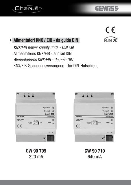
<strong>Alimentatori</strong> <strong>KNX</strong> / EIB - da guida DIN<br />
<strong>KNX</strong>/EIB power supply units - DIN rail<br />
Alimentateurs <strong>KNX</strong>/EIB - sur rail DIN<br />
Alimentadores <strong>KNX</strong>/EIB - de guía DIN<br />
<strong>KNX</strong>/EIB-Spannungsversorgung - für DIN-Hutschiene<br />
<strong>GW</strong> <strong>90</strong> <strong>709</strong><br />
<strong>320</strong> <strong>mA</strong><br />
<strong>GW</strong> <strong>90</strong> <strong>710</strong><br />
<strong>640</strong> <strong>mA</strong>
A<br />
1<br />
B<br />
L N<br />
2<br />
3<br />
4<br />
5<br />
6<br />
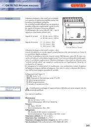
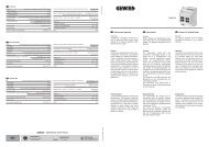
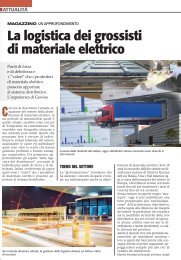
1 Morsetti di alimentazione -<br />
Power terminals -<br />
Bornes d’alimentation -<br />
Bornes de alimentación -<br />
Versorgungsklemmen<br />
2 Led di funzionamento -<br />
Operating status LED -<br />
Led de fonctionnement -<br />
Led de funcionamiento -<br />
LED Betrieb<br />
3 Led di sovracorrente -<br />
Over-current LED -<br />
Led de surintensité -<br />
Led de sobrecorriente -<br />
LED Überstrom<br />
4 Led di reset - Reset LED -<br />
Led de reset - Led de reset -<br />
LED Rückstellung<br />
5 Pulsante di reset -<br />
Reset button - Bouton de reset -<br />
Pulsador de reset - Rückstelltaste<br />
6 Terminali BUS <strong>KNX</strong> -<br />
BUS <strong>KNX</strong> terminals -<br />
Borniers BUS <strong>KNX</strong> -<br />
Terminales BUS <strong>KNX</strong> -<br />
BUS-<strong>KNX</strong> Anschlüsse<br />
BUS <strong>KNX</strong> EIB - +<br />
C<br />
Bus<br />
≥ 4 mm<br />
230 V
INDICE<br />
pag.<br />
AVVERTENZE GENERALI....................................................................................... 4<br />
DESCRIZIONE GENERALE ..................................................................................... 5<br />
INSTALLAZIONE.................................................................................................... 6<br />
I<br />
T<br />
A<br />
L<br />
I<br />
A<br />
N<br />
O<br />
DATI TECNICI ........................................................................................................ 8<br />
3
AVVERTENZE GENERALI<br />
Attenzione! La sicurezza dell’apparecchio è garantita solo attendendosi alle istruzioni qui<br />
riportate. Pertanto è necessario leggerle e conservarle. I prodotti Chorus devono essere<br />
installati conformemente a quanto previsto dalla norma CEI 64-8 per gli apparecchi per<br />
uso domestico e similare, in ambienti non polverosi e dove non sia necessaria una<br />
protezione speciale contro la penetrazione di acqua.<br />
L’organizzazione di vendita GEWISS è a disposizione per chiarimenti e informazioni<br />
tecniche.<br />
<strong>Gewiss</strong> SpA si riserva il diritto di apportare modifiche al prodotto descritto in questo<br />
manuale in qualsiasi momento e senza alcun preavviso.<br />
n. 1 Alimentatore <strong>KNX</strong>/EIB - da guida DIN<br />
n. 1 Morsetto bus<br />
n. 1 Coperchietto con vite<br />
n. 1 Manuale di installazione e uso<br />
Contenuto della confezione<br />
4
DESCRIZIONE GENERALE<br />
Funzioni<br />
L’alimentatore <strong>KNX</strong>/EIB fornisce l’alimentazione necessaria ai dispositivi di una linea bus<br />
<strong>KNX</strong>/EIB, generando una bassissima tensione di sicurezza (SELV) di 30 Vcc.<br />
La corrente massima di uscita è di <strong>320</strong> <strong>mA</strong> per l’alimentatore <strong>GW</strong><strong>90</strong><strong>709</strong> e di <strong>640</strong> <strong>mA</strong> per<br />
l’alimentatore <strong>GW</strong><strong>90</strong><strong>710</strong>: la scelta del tipo di alimentatore è funzione dell’assorbimento<br />
massimo dei dispositivi <strong>KNX</strong> connessi sulla linea. Per ogni linea bus è richiesta la<br />
presenza di almeno un alimentatore. L’alimentatore integra una bobina di<br />
disaccoppiamento interna allo scopo di isolare il traffico dati dall’alimentazione. Il<br />
collegamento al bus è realizzato attraverso apposito morsetto nero/rosso.<br />
L’alimentatore è protetto contro il corto circuito e prevede una limitazione della corrente<br />
massima di uscita.<br />
Il LED verde (Operation) segnala quando l’alimentatore è pronto per il funzionamento.<br />
Un assorbimento troppo elevato di corrente (I>Imax) è segnalato attraverso il LED rosso<br />
di sovracorrente (Overload).<br />
Il pulsante di RESET permette il reset di tutti i dispositivi connessi sul bus.<br />
Quando il pulsante viene premuto brevemente, utilizzando un utensile appuntito, la<br />
tensione di uscita è interrotta per un tempo di 20 secondi.<br />
I<br />
T<br />
A<br />
L<br />
I<br />
A<br />
N<br />
O<br />
SIGNIFICATO DEI LED<br />
Durante una operazione di RESET il led rosso di RESET è acceso.<br />
LED di funzionamento<br />
Operation (verde)<br />
LED di sovracorrente<br />
I>Imax (rosso)<br />
ON OFF Normale funzionamento<br />
ON<br />
ON<br />
Sovracorrente: la corrente in<br />
uscita è troppo elevata (I>Imax)<br />
OFF ON Linea bus in corto circuito<br />
OFF OFF Dispositivo non alimentato<br />
In caso di sovracorrente, rimuovere dal bus i dispositivi che causano l’assorbimento di<br />
corrente oltre la soglia di corrente massima di uscita.<br />
In caso di corto circuito della linea bus rimuovere la causa del corto circuito.<br />
Entro 6 secondi max. l'alimentatore ripristina la tensione in uscita.<br />
5
INSTALLAZIONE<br />
ATTENZIONE: l’installazione del dispositivo deve essere effettuata<br />
esclusivamente da personale qualificato, seguendo la normativa<br />
vigente e le linee guida per le installazioni <strong>KNX</strong>/EIB.<br />
Avvertenze per l’installazione <strong>KNX</strong>/EIB<br />
1. La distanza massima tra l’alimentatore ed il dispositivo <strong>KNX</strong> più lontano nell’impianto<br />
deve essere di 350m.<br />
2. Su una stessa linea possono essere presenti al massimo 2 alimentatori; in tal caso la<br />
distanza tra i due alimentatori deve essere almeno di 200m.<br />
3. Nel caso in cui in una installazione siano presenti 30 o più dispositivi <strong>KNX</strong> su un cavo<br />
di lunghezza inferiore od uguale ai 10m (esempio quadri di distribuzione) è necessario<br />
posizionare l’alimentatore nelle immediate vicinanze.<br />
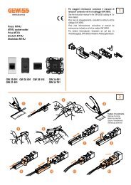
4. Mantenere una distanza di almeno 4 mm tra i cavi singolarmente isolati della linea bus<br />
e quelli della linea elettrica (figura C).<br />
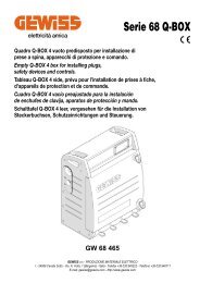
5. Non danneggiare il conduttore di continuità elettrica della schermatura (figura D).<br />
ATTENZIONE: i cavi di segnale del bus non utilizzati e il conduttore di<br />
continuità elettrica non devono mai toccare elementi sotto tensione o<br />
il conduttore di terra!<br />
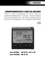
Montaggio su guida DIN<br />
Montare l'alimentatore su guida DIN da 35 mm nel seguente modo (figura E):<br />
1. Inserire l’aggancio superiore del dispositivo nella guida DIN.<br />
2. Ruotare il dispositivo finché non si sente un “clack” che segnala il bloccaggio sulla<br />
guida DIN.<br />
6
INSTALLAZIONE<br />
Connessioni elettriche<br />
ATTENZIONE: disinserire la tensione di rete prima di connettere il<br />
dispositivo alla rete elettrica!<br />
La figura B mostra lo schema delle connessioni elettriche.<br />
1. Connettere il filo rosso del cavo bus al morsetto rosso (+) del terminale e il filo nero<br />
al morsetto nero (-). Al terminale bus si possono collegare fino a 4 linee bus (fili dello<br />
stesso colore nello stesso morsetto) (figura F).<br />
2. Isolare lo schermo, il conduttore di continuità elettrica e i rimanenti fili bianco e giallo<br />
del cavo bus (nel caso in cui si utilizzi un cavo bus a 4 conduttori), che non sono<br />
necessari (figura D).<br />
3. Inserire il morsetto bus negli appositi piedini del dispositivo. Il corretto senso di<br />
inserzione è determinato dalle guide di fissaggio. Isolare il morsetto bus usando<br />
l’apposito coperchietto, che deve essere fissato al dispositivo con la sua vite.<br />
Il coperchietto garantisce la separazione minima di 4 mm tra i cavi di potenza e i cavi<br />
bus (figura G).<br />
4. Collegare l'alimentazione agli appositi morsetti a vite.<br />
I<br />
T<br />
A<br />
L<br />
I<br />
A<br />
N<br />
O<br />
7
DATI TECNICI<br />
Tensione di alimentazione in ingresso 110 - 240 Vca, 50-60 Hz<br />
Potenza massima assorbita (<strong>GW</strong><strong>90</strong><strong>709</strong>) 25 VA<br />
(<strong>GW</strong><strong>90</strong><strong>710</strong>) 50 VA<br />
Potenza dissipata (<strong>GW</strong><strong>90</strong><strong>709</strong>) 4 W<br />
(<strong>GW</strong><strong>90</strong><strong>710</strong>) 8 W<br />
Tensione di uscita<br />
30 Vcc ± 2 Vcc (SELV)<br />
Corrente massima di uscita (<strong>GW</strong><strong>90</strong><strong>709</strong>) <strong>320</strong> <strong>mA</strong><br />
(<strong>GW</strong><strong>90</strong><strong>710</strong>) <strong>640</strong> <strong>mA</strong><br />
Corrente di corto circuito (<strong>GW</strong><strong>90</strong><strong>709</strong>) < 1 A<br />
(<strong>GW</strong><strong>90</strong><strong>710</strong>) < 1,5 A<br />
Tempo di back up (a corrente nominale) 200 ms circa<br />
Elementi di visualizzazione<br />
1 LED verde di funzionamento<br />
1 LED rosso di sovracorrente<br />
1 LED rosso di reset<br />
Elementi di comando<br />
1 pulsante di reset<br />
(accessibile con utensile appuntito)<br />
Ambiente di utilizzo<br />
Interno, luoghi asciutti<br />
Temperatura di funzionamento -5 ÷ +45 °C<br />
Temperatura di stoccaggio -25 ÷ +70 °C<br />
Umidità relativa<br />
Max 93% (non condensante)<br />
Connessione al bus<br />
Morsetto ad innesto, 2 pin Ø 1 mm<br />
Connessioni elettriche<br />
Morsetti a vite<br />
Sezione max. cavi 2,5 mm 2<br />
Grado di protezione<br />
IP20<br />
Dimensione<br />
4 moduli DIN<br />
Riferimenti normativi<br />
Direttiva bassa tensione 2006/95/CE<br />
Direttiva compatibilità elettromagnetica<br />
2004/108/CE<br />
EN 500<strong>90</strong><br />
Certificazioni<br />
<strong>KNX</strong>/EIB<br />
8
CONTENTS<br />
page<br />
GENERAL INFORMATION ..................................................................................... 10<br />
GENERAL DESCRIPTION ....................................................................................... 11<br />
INSTALLATION ...................................................................................................... 12<br />
TECHNICAL DATA ................................................................................................. 14<br />
E<br />
N<br />
G<br />
L<br />
I<br />
S<br />
H<br />
9
GENERAL INFORMATION<br />
Warning! The safety of this appliance is only guaranteed if all the instructions given here<br />
are followed scrupulously. These should be read thoroughly and kept in a safe place.<br />
The Chorus products must be installed in compliance with the requisites of standard CEI<br />
64-8 for devices for domestic use and similar, in non-dusty atmospheres and where<br />
special protection against water penetration is not required.<br />
The GEWISS sales organisation is at your disposal for clarifications and technical<br />
information.<br />
<strong>Gewiss</strong> SpA reserves the right to make changes to the product described in this manual<br />
at any time and without giving any notice.<br />
n. 1 <strong>KNX</strong>/EIB power supply unit - DIN rail<br />
n. 1 Bus terminal<br />
n. 1 Cover with screw<br />
n. 1 Installation and user manual<br />
Pack content<br />
10
GENERAL DESCRIPTION<br />
Functions<br />
The <strong>KNX</strong>/EIB power supply unit supplies the power needed by the <strong>KNX</strong>/EIB bus line<br />
devices, generating a safety extra low voltage (SELV) of 30 Vdc.<br />
The maximum output current is <strong>320</strong> <strong>mA</strong> for the <strong>GW</strong><strong>90</strong><strong>709</strong> power supply unit and <strong>640</strong> <strong>mA</strong><br />
for the <strong>GW</strong><strong>90</strong><strong>710</strong> power supply unit: the choice of supply unit depends on the maximum<br />
current consumption of the <strong>KNX</strong> devices connected to the line. Each bus line requires at<br />
least one power supply unit. The power supply unit integrates an internal choke to isolate<br />
data traffic from the power supply. A special red/black terminal is used to connect it to<br />
the bus.<br />
The power supply unit is protected against short-circuits and has a maximum output<br />
current limit.<br />
The green LED (Operating status) indicates when the power supply unit is ready.<br />
The red over-current LED indicates that there is an excessive current consumption<br />
(l>lmax).<br />
The RESET button resets all the devices connected to the bus.<br />
When the button is pressed briefly, using a sharp tool, the output voltage will be<br />
interrupted for 20 seconds.<br />
E<br />
N<br />
G<br />
L<br />
I<br />
S<br />
H<br />
LED KEY<br />
During a RESET operation, the red RESET LED is ON.<br />
Operating status<br />
LED (green)<br />
Over-current LED<br />
l>lmax (red)<br />
ON OFF Normal operation<br />
ON<br />
ON<br />
Over-current: the output<br />
current is too high (l>lmax)<br />
OFF ON Bus line in short-circuit<br />
OFF OFF Device not powered<br />
In the event of an over-current, disconnect the devices that cause the current<br />
consumption over the maximum output threshold.<br />
In the event of a short-circuit, disconnect the cause of the short-circuit.<br />
Within max. 6 seconds the power supply restores the output current.<br />
11
INSTALLATION<br />
WARNING: the installation of the device must be exclusively done by<br />
qualified personnel, following the regulations in force and the<br />
guidelines for <strong>KNX</strong>/EIB installations.<br />
Warnings for <strong>KNX</strong>/EIB installations<br />
1. The maximum distance between the power supply unit and the <strong>KNX</strong> device furthest<br />
away from the unit is 350 m.<br />
2. A maximum of 2 power supply units can be installed on any one line; in this case the<br />
distance between the two power supply units must be at least 200m.<br />
3. If 30 or more <strong>KNX</strong> devices are installed on one cable which is 10 m or less in length<br />
(for instance distribution boards) it is necessary to position the power supply unit in<br />
the immediate vicinity.<br />
4. Keep a distance of at least 4 mm between the individually insulated cables of the bus<br />
line and those of the electric line (figure C).<br />
5. Do not damage the electrical continuity conductor of the shielding (figure D).<br />
WARNING: the unused bus signal cables and the electrical continuity<br />
conductor must never touch elements under power or the earth<br />
conductor!<br />
Assembly on a DIN rail<br />
Fit the power supply unit to a 35 mm DIN rail as follows (figure E):<br />
1. Insert the device’s upper coupling in the DIN rail.<br />
2. Rotate the device until a “click” is heard, signalling locking to the DIN rail.<br />
12
INSTALLATION<br />
Electrical connections<br />
WARNING: cut off mains power before connecting the device to the<br />
electricity mains!<br />
Figure B shows the electrical connections diagram.<br />
1. Connect the bus cable’s red wire to the terminal’s red connector (+) and the black wire<br />
to the black connector (-). Up to 4 bus lines (wires of the same colour in the same<br />
connector) can be connected to the terminal (figure F).<br />
2. Insulate the screen, the electrical continuity conductor and the remaining white and<br />
yellow wires of the bus cable (should a bus cable with 4 conductors be used), which<br />
are not needed (figure D).<br />
3. Insert the bus connector into the special pins of the device. The fastener guides<br />
determine the direction it should be inserted. Insulate the bus terminal using the<br />
relative cover, which must be screwed onto the device.<br />
The cover guarantees that the power cables and the bus cables are separated by at<br />
least 4 mm (figure G).<br />
4. Connect the power supply to the relative screw terminals.<br />
E<br />
N<br />
G<br />
L<br />
I<br />
S<br />
H<br />
13
TECHNICAL DATA<br />
Input power supply voltage:<br />
110-240Vac, 50-60 Hz<br />
Maximum power consumption (<strong>GW</strong><strong>90</strong><strong>709</strong>) 25 VA<br />
(<strong>GW</strong><strong>90</strong><strong>710</strong>) 50 VA<br />
Dispersed power (<strong>GW</strong><strong>90</strong><strong>709</strong>) 4W<br />
(<strong>GW</strong><strong>90</strong><strong>710</strong>) 8W<br />
Output voltage<br />
30Vdc ± 2Vdc (SELV)<br />
Maximum output current (<strong>GW</strong><strong>90</strong><strong>709</strong>) <strong>320</strong> <strong>mA</strong><br />
(<strong>GW</strong><strong>90</strong><strong>710</strong>) <strong>640</strong> <strong>mA</strong><br />
Short-circuit current (<strong>GW</strong><strong>90</strong><strong>709</strong>)
SOMMAIRE<br />
page<br />
AVERTISSEMENTS GENERAUX ............................................................................ 16<br />
DESCRIPTION GENERALE ................................................................................... 17<br />
INSTALLATION ..................................................................................................... 18<br />
DONNEES TECHNIQUES ....................................................................................... 20<br />
F<br />
R<br />
A<br />
N<br />
Ç<br />
A<br />
I<br />
S<br />
15
AVERTISSEMENTS GENERAUX<br />
Attention ! La sécurité de l'appareil n'est garantie que si les instructions indiquées ici<br />
sont respectées. Il est donc nécessaire de les lire et de bien les conserver. Les produits<br />
de la gamme Chorus doivent être installés conformément aux dispositions de la norme<br />
CEI 64-8 pour les appareils à usage domestique et similaires, dans des environnements<br />
non poussiéreux et là où il n’est pas nécessaire de mettre en place une protection<br />
spéciale contre la pénétration de l’eau.<br />
L’organisation de vente de la Société GEWISS est à votre disposition pour tous<br />
éclaircissements et toutes informations techniques.<br />
<strong>Gewiss</strong> SpA se réserve le droit de faire des modifications sur le produit décrit dans ce<br />
manuel à n’importe quel moment et sans aucun préavis.<br />
n. 1 Alimentateur <strong>KNX</strong>/EIB - sur rail DIN<br />
n. 1 Borne bus<br />
n. 1 Couvercle avec vis<br />
n. 1 Manuel d’installation et d’emploi<br />
Contenu de la confection<br />
16
DESCRIPTION GENERALE<br />
En Fonctions<br />
L’alimentateur <strong>KNX</strong>/EIB fournit l’alimentation nécessaire aux dispositifs d'une ligne bus<br />
<strong>KNX</strong>/EIB, en engendrant une tension de sécurité très basse (SELV) de 30 Vcc.<br />
Le courant maximum de sortie est de <strong>320</strong> <strong>mA</strong> pour l’alimentateur <strong>GW</strong><strong>90</strong><strong>709</strong>, et de <strong>640</strong><br />
<strong>mA</strong> pour l’alimentateur <strong>GW</strong><strong>90</strong><strong>710</strong> : le choix du type d’alimentateur dépend de l’absorption<br />
maximale des dispositifs <strong>KNX</strong> qui sont connectés sur la ligne. Pour chaque ligne bus est<br />
requise la présence d’au moins un alimentateur. L’alimentateur contient une bobine<br />
interne, dans le but d’isoler le trafic de données de l’alimentation. La connexion au bus<br />
est réalisée par la borne noire/rouge.<br />
L’alimentateur est protégé contre les courts-circuits et prévoit une limitation du courant<br />
maximum de sortie.<br />
La LED verte (Operation) signale lorsque l’alimentateur est prêt à fonctionner.<br />
Une absorption de courant trop élevée (l>lmax) est signalée par la LED rouge de<br />
surintensité (Overload).<br />
Le bouton de RESET permet de réinitialiser tous les dispositifs connectés sur le bus.<br />
Quand on appuie brièvement sur le bouton, en utilisant un outil pointu, on interrompt la<br />
tension de sortie pendant une période de 20 secondes.<br />
SIGNIFICATION DES LED<br />
Pendant une opération de RESET, la led rouge de RESET est allumée.<br />
LED de fonctionnement<br />
Operation (vert)<br />
LED de surintensité<br />
l>lmax (rouge)<br />
F<br />
R<br />
A<br />
N<br />
Ç<br />
A<br />
I<br />
S<br />
ON OFF Fonctionnement normal<br />
ON<br />
ON<br />
Surintensité : le courant en sortie<br />
est trop élevé (l>lmax)<br />
OFF ON Ligne bus en court-circuit<br />
OFF OFF Dispositif non alimenté<br />
En cas de surintensité de courant, enlever du bus les dispositifs qui causent l’absorption<br />
de courant au-delà du seuil de courant maximum de sortie.<br />
En cas de court-circuit de la ligne bus, éliminer la cause du court-circuit.<br />
Au plus tard 6 secondes l'alimentateur retablit le courant de sortie.<br />
17
INSTALLATION<br />
ATTENTION: l’installation du dispositif ne doit être effectuée que par<br />
du personnel qualifié, conformément à la réglementation en vigueur et<br />
aux lignes directrices pour les installations <strong>KNX</strong>/EIB.<br />
Avertissements pour l’installation <strong>KNX</strong>/EIB<br />
1. La distance maximale entre l’alimentateur et le dispositif <strong>KNX</strong> le plus loin de<br />
l’installation doit être de 350 m.<br />
2. Sur une même ligne il peut y avoir au maximum 2 alimentateurs ; dans ce cas la<br />
distance entre les deux alimentateurs doit être d’au moins 200 m.<br />
3. Au cas où il y a dans une installation 30 dispositifs <strong>KNX</strong> ou plus sur un câble de moins<br />
de ou égal à 10 m de long (exemple tableaux de distribution), il est nécessaire de<br />
placer l’alimentateur à proximité immédiate.<br />
4. Maintenir une distance d’au moins 4 mm entre les câbles isolés un par un de la ligne<br />
bus, et les câbles de la ligne électrique (figure C)<br />
5. Ne pas endommager le conducteur de continuité électrique du blindage (figure D).<br />
ATTENTION: les câbles de signal du bus non utilisés et le conducteur de<br />
continuité électrique ne doivent jamais toucher des éléments sous<br />
tension ni le conducteur de terre !<br />
Montage sur rail DIN<br />
Monter l’alimentateur sur le rail DIN de 35 mm de la façon suivante (figure E) :<br />
1. Insérer l’accrochage supérieur du dispositif dans le rail DIN.<br />
2. Faire tourner le dispositif jusqu’à ce qu’on entende un « clack » qui signale le blocage<br />
sur le rail DIN.<br />
18
Connexions électriques<br />
ATTENTION: débrancher la tension de secteur avant de connecter le<br />
dispositif au secteur !<br />
La figure B montre le schéma des connexions électriques.<br />
1. Connecter le fil rouge du câble bus à la borne rouge (+) du terminal, et le fil noir à la<br />
borne noire (-). On peut relier au terminal bus jusqu’à 4 lignes bus (fils de la même<br />
couleur dans la même borne) (figure F).<br />
2. Isoler l’écran, le conducteur de continuité électrique et les fils restants blanc et jaune<br />
du câble bus (au cas où l’on utilise un câble bus à 4 conducteurs), qui ne sont pas<br />
nécessaires (figure D).<br />
3. Brancher la borne bus dans les pieds du dispositif prévus. Le sens correct d’insertion<br />
est déterminé par les guides de fixation. Isoler la borne bus en utilisant le petit<br />
couvercle prévu, qui doit être fixé au dispositif avec sa vis.<br />
Le petit couvercle garantit la séparation minimale de 4 mm entre les câbles de<br />
puissance et les câbles bus (figure G).<br />
4. Connecter l’alimentation aux bornes à vis prévues.<br />
F<br />
R<br />
A<br />
N<br />
Ç<br />
A<br />
I<br />
S<br />
19
DONNEES TECHNIQUES<br />
Tension d’alimentation en entrée 110-240Vca, 50-60 Hz<br />
Puissance maximum absorbée (<strong>GW</strong><strong>90</strong><strong>709</strong>) 25 VA<br />
(<strong>GW</strong><strong>90</strong><strong>710</strong>) 50 VA<br />
Puissance dissipée (<strong>GW</strong><strong>90</strong><strong>709</strong>) 4W<br />
(<strong>GW</strong><strong>90</strong><strong>710</strong>) 8W<br />
Tension en sortie<br />
30Vcc ± 2Vcc (SELV)<br />
Courant maximum de sortie (<strong>GW</strong><strong>90</strong><strong>709</strong>) <strong>320</strong> <strong>mA</strong><br />
(<strong>GW</strong><strong>90</strong><strong>710</strong>) <strong>640</strong> <strong>mA</strong><br />
Courant de court circuit (<strong>GW</strong><strong>90</strong><strong>709</strong>)
ÍNDICE<br />
pág.<br />
ADVERTENCIAS GENERALES................................................................................ 22<br />
DESCRIPCIÓN GENERAL....................................................................................... 23<br />
INSTALACIÓN........................................................................................................ 24<br />
DATOS TÉCNICOS ................................................................................................. 26<br />
E<br />
S<br />
P<br />
A<br />
Ñ<br />
O<br />
L<br />
21
ADVERTENCIAS GENERALES<br />
¡Atención! La seguridad del aparato está garantizada sólo si se respetan las<br />
instrucciones aquí indicadas. Por lo tanto es necesario leerlas y conservarlas. Los<br />
productos Chorus deben instalarse conforme a lo previsto por la norma CEI 64-8 para los<br />
aparatos de uso doméstico y similar, en ambientes sin polvo y donde no sea necesaria<br />
una protección especial contra la penetración de agua.<br />
La organización de venta GEWISS se encuentra a su disposición para informaciones<br />
técnicas.<br />
<strong>Gewiss</strong> SpA se reserva el derecho de introducir cambios al producto descrito en este<br />
manual en cualquier momento y sin preaviso.<br />
n. 1 Alimentador <strong>KNX</strong>/EIB - de guía DIN<br />
n. 1 Borna bus<br />
n. 1 Tapa con tornillo<br />
n. 1 Manual de instalación y uso<br />
Contenido del embalaje<br />
22
DESCRIPCIÓN GENERAL<br />
Funciones<br />
El alimentador <strong>KNX</strong>/EIB suministra la alimentación necesaria a los dispositivos de una<br />
línea bus <strong>KNX</strong>/EIB, generando una bajísima tensión de seguridad (SELV) de 30 Vcc.<br />
La corriente máxima de salida es de <strong>320</strong> <strong>mA</strong> para el alimentador <strong>GW</strong><strong>90</strong><strong>709</strong> y de <strong>640</strong> <strong>mA</strong><br />
para el alimentador <strong>GW</strong><strong>90</strong><strong>710</strong>: la elección del tipo de alimentador es función de la<br />
absorción máxima de los dispositivos <strong>KNX</strong> conectados en la línea. Para cada línea bus<br />
se requiere la presencia de al menos un alimentador. El alimentador integra una bobina<br />
de desacoplo interna con el objetivo de aislar el tráfico de datos de la alimentación. La<br />
conexión al bus está realizada por medio de un apropiado borne negro/rojo.<br />
El alimentador está protegido contra cortocircuito y prevé una limitación de la corriente<br />
máxima de salida.<br />
El LED verde (Operation) señala cuando el alimentador está listo para el funcionamiento.<br />
Una absorción demasiado elevada de corriente (l>lmax) es señalada por medio del LED<br />
rojo de sobrecorriente (Overload).<br />
El pulsador de RESET permite el reset de todos los dispositivos conectados en el bus.<br />
Cuando el pulsador se presiona brevemente, utilizando una herramienta puntiaguda, la<br />
tensión de salida se interrumpe durante un tiempo de 20 segundos.<br />
SIGNIFICADO DE LOS LEDS<br />
Durante una operación de RESET el led rojo de RESET está encendido.<br />
LED de funcionamiento<br />
Operation (verde)<br />
LED di sovracorrente<br />
I>Imax (rojo)<br />
ON OFF Normal funcionamiento<br />
ON<br />
ON<br />
Sobrecorriente: la corriente en salida<br />
es demasiado elevada (l>lmax)<br />
OFF ON Linea bus in corto circuito<br />
E<br />
S<br />
P<br />
A<br />
Ñ<br />
O<br />
L<br />
OFF OFF Dispositivo no alimentado<br />
En caso de sobrecorriente, extraer del bus los dispositivos que causan la absorción de<br />
corriente más allá del umbral de corriente máximo de salida.<br />
En caso de cortocircuito de la línea bus eliminar la causa del cortocircuito.<br />
Dentro de 6 secundos max. el alimentador restablecerá la tensión de salida.<br />
23
INSTALACIÓN<br />
ATENCIÓN: La instalación del dispositivo debe efectuarse<br />
exclusivamente por personal cualificado, siguiendo las normativas<br />
vigente y las líneas guía para las instalaciones <strong>KNX</strong>/EIB.<br />
Advertencias para la instalación <strong>KNX</strong>/EIB<br />
1. La distancia máxima entre el alimentador y el dispositivo <strong>KNX</strong> más lejano en la<br />
instalación debe ser de 350m.<br />
2. En una misma línea pueden estar presentes al máximo 2 alimentadores, en dicho<br />
caso, la distancia entre los dos alimentadores debe ser al menos de 200m.<br />
3. Si en una instalación hay presentes 30 o más dispositivos <strong>KNX</strong> en un cable de longitud<br />
inferior o igual a los 10m (ejemplo cuadros de distribución) es necesario posicionar<br />
el alimentador en las inmediatas cercanías.<br />
4. Mantener una distancia de al menos 4 mm entre los cables individualmente aislados<br />
de la línea bus y los de la línea eléctrica (figura C).<br />
5. No dañe el conductor de continuidad eléctrica del blindaje (figura D).<br />
ATENCIÓN: ¡los cables de señal del bus no utilizados y el conductor de<br />
continuidad eléctrica no deben nunca tocar elementos bajo tensión o<br />
el conductor de tierra!<br />
Montaje en guía DIN<br />
Montar el alimentador en guía DIN de 35 mm del siguiente modo (figura E):<br />
1. Introducir el enganche superior del dispositivo en la guía DIN.<br />
2. Girar el dispositivo hasta que se escuche un "clack" que señala el bloqueo en la<br />
guía DIN.<br />
24
INSTALACIÓN<br />
Conexiones eléctricas<br />
ATENCIÓN: ¡desconectar la tensión de red antes de conectar el<br />
dispositivo a la red eléctrica!<br />
La figura B muestra el esquema de las conexiones eléctricas.<br />
1. Conectar el cable rojo del cable bus a la borna roja (+) del terminal y el cable negro<br />
a la borna negra (-). Al terminal bus se pueden conectar hasta 4 líneas bus (cables del<br />
mismo color en la misma borna) (figura F).<br />
2. Aislar la pantalla, el conductor de continuidad eléctrica y los cables blanco y amarillo<br />
del cable bus (en el caso de que se utilice un cable bus de 4 conductores), que no son<br />
necesarios (figura D).<br />
3. Introducir el conector bus en el borne específico del dispositivo. El sentido correcto<br />
de inserción está determinado por las guías de fijación. Aislar el borne bus usando la<br />
tapa correspondiente, fijándola al dispositivo con un tornillo.<br />
La tapa garantiza la separación mínima de 4 mm entre los cables de potencia y los<br />
cable bus (figura G).<br />
4. Conectar el alimentador a los correspondientes bornes con tornillo.<br />
E<br />
S<br />
P<br />
A<br />
Ñ<br />
O<br />
L<br />
25
DATOS TÉCNICOS<br />
Tensión de alimentación en entrada 110-240Vca, 50-60 Hz<br />
Potencia máxima absorbida (<strong>GW</strong><strong>90</strong><strong>709</strong>) 25 VA<br />
(<strong>GW</strong><strong>90</strong><strong>710</strong>) 50 VA<br />
Potencia disipada (<strong>GW</strong><strong>90</strong><strong>709</strong>) 4W<br />
(<strong>GW</strong><strong>90</strong><strong>710</strong>) 8W<br />
Tensión de salida<br />
30Vcc ± 2Vcc (SELV)<br />
Corriente máxima de salida (<strong>GW</strong><strong>90</strong><strong>709</strong>) <strong>320</strong> <strong>mA</strong><br />
(<strong>GW</strong><strong>90</strong><strong>710</strong>) <strong>640</strong> <strong>mA</strong><br />
Corriente de cortocircuito (<strong>GW</strong><strong>90</strong><strong>709</strong>)
ALLGEMEINE HINWEISE<br />
Achtung! Die Gerätesicherheit ist nur dann gegeben, wenn die nachfolgenden<br />
Anweisungen eingehalten werden. Daher sind diese zu lesen, und aufzubewahren. Die<br />
Produkte Chorus müssen gemäß der Norm CEI 64-8 für Anwendung im Wohnbereich<br />
oder ähnlich, in staubarmer Umgebung, wo kein besonderer Schutz gegen Eindringen von<br />
Wasser erforderlich ist, installiert werden.<br />
Die GEWISS Verkaufsabteilung steht für weitergehende Erläuterungen und technische<br />
Informationen gerne zur Verfügung.<br />
<strong>Gewiss</strong> SpA behält sich das Recht vor, jederzeit und ohne vorherige Mitteilung<br />
Änderungen an dem in dieser Bedienungsanleitung beschriebenen Produkt vorzunehmen.<br />
Packungsinhalt<br />
1 St. <strong>KNX</strong>/EIB-Spannungsversorgung - für DIN-Hutschiene<br />
1 St. Busklemme<br />
1 St. Deckel einschl. Schraube<br />
1 St. Installations- und Bedienungsanleitung<br />
28
ALLGEMEINE BESCHREIBUNG<br />
Kurzbeschreibung<br />
Die <strong>KNX</strong>/EIB Spannungsversorgung liefert die erforderliche Stromversorgung für die<br />
Geräte einer <strong>KNX</strong>/EIB Buslinie, und generiert eine sehr niedrige Sicherheitsspannung<br />
(SELV) von 30 V Gleichspannung.<br />
Der maximale Ausgangsstrom beträgt bei der Spannungsversorgung <strong>GW</strong><strong>90</strong><strong>709</strong> <strong>320</strong> <strong>mA</strong> und<br />
bei der Spannungsversorgung <strong>GW</strong><strong>90</strong><strong>710</strong> <strong>640</strong> <strong>mA</strong>. Die Auswahl der Spannungsversorgung<br />
erfolgt anhand der maximalen Leistungsaufnahme der angeschlossenen <strong>KNX</strong>-Geräte. Jede<br />
Buslinie erfordert mindestens eine Spannungsversorgung. In der Spannungsversorgung<br />
befindet sich eine Drossel, um den Datenverkehr von der Stromversorgung zu trennen. Die<br />
Verbindung mit dem Bus erfolgt mittels der entsprechenden schwarz/roten Klemme. Die<br />
Spannungsversorgung ist geschützt gegen Kurzschlüsse und verfügt über eine Begrenzung<br />
des maximalen Ausgangsstroms.<br />
Die grüne LED (Operation) zeigt an, wenn die Spannungsversorgung betriebsbereit ist.<br />
Ein zu hohe Stromaufnahme (I>Imax) wird durch das Einschalten der roten Überstrom-<br />
LED (Overload) angezeigt. Mit der RESET Taste können alle an den Bus angeschlossenen<br />
Geräte zurück gesetzt werden.<br />
Beim kurzen Drücken der Taste mit einem spitzen Werkzeug wird die Ausgangsspannung<br />
für 20 Sekunden unterbrochen.<br />
BEDEUTUNG DER LED<br />
Bei einem RESET-Vorgang schaltet sich die rote RESET LED ein.<br />
Betriebs-LED<br />
Operation (grün)<br />
Überstrom-LED<br />
I>Imax (rot)<br />
EIN AUS Normaler Betrieb<br />
EIN<br />
EIN<br />
Bei Überstrom müssen die Geräte vom Bus getrennt werden, die ein Überschreiten des<br />
maximalen Stromausgangswert verursacht haben.<br />
Bei einem Kurzschluss der Buslinie muss die Kurzschlussursache beseitigt werden.<br />
Innerhalb von 6 sekunden maximal wiederstellt die Spannungsversorgung die<br />
Ausgangsstrom.<br />
29<br />
Überstrom: Der Ausgangsstrom<br />
ist zu hoch (I>Imax)<br />
AUS EIN Kurzschluss der Buslinie<br />
AUS<br />
AUS<br />
Keine Stromversorgung<br />
des Geräts<br />
D<br />
E<br />
U<br />
T<br />
S<br />
C<br />
H
INSTALLATION<br />
ACHTUNG: Ausschließlich qualifiziertes Personal darf die Vorrichtung<br />
entsprechend den geltenden Richtlinien und Leitfäden für <strong>KNX</strong>/EIB-<br />
Installationen installieren.<br />
Hinweise zur Installation <strong>KNX</strong>/EIB<br />
1. Die maximale Entfernung zwischen Spannungsversorgung und dem am weitesten<br />
entfernten <strong>KNX</strong>-Gerät der Anlage beträgt 350 m.<br />
2. In der gleichen Linie können maximal 2 Spannungsversorgungen installiert sein; in<br />
diesem Fall muss der Abstand zwischen den beiden Spannungsversorgungen<br />
mindestens 200 m betragen.<br />
3. Falls in einer Installationssituation 30 oder mehr <strong>KNX</strong>-Geräte auf einer Kabellänge von<br />
10 m, oder weniger, installiert sind (z.B.Verteilerkasten), muss die Spannungsversorgung<br />
in unmittelbarer Nähe installiert werden.<br />
4. Ein Abstand von mindestens 4 mm ist zwischen den einzelnen, isolierten Kabeln der<br />
Busleitung und denen der elektrischen Leitung einzuhalten (Abbildung C).<br />
5. Der Stromdurchgangsleiter der Abschirmung darf nicht beschädigt werden<br />
(Abbildung D).<br />
ACHTUNG: Die nicht benutzten Signalkabel des Busses und der<br />
Stromdurchgangsleiter dürfen keinesfalls mit Strom führenden<br />
Elementen oder dem Erdleiter in Berührung kommen!<br />
Montage auf DIN-Schiene<br />
Die Spannungsversorgung auf folgende Weise auf der 35 mm DIN-Hutschiene montieren<br />
(Abb. E):<br />
1. Schieben Sie die obere Einrastvorrichtung in die DIN-Schiene.<br />
2. Drehen Sie die Vorrichtung, bis Sie ein „Klack“ hören; die Vorrichtung ist in der DIN-<br />
Schiene eingerastet.<br />
30
INSTALLATION<br />
Elektrische Anschlüsse<br />
ACHTUNG: Die Netzspannung muss abgeschaltet werden, bevor die<br />
Vorrichtung an das Stromnetz angeschlossen wird!<br />
In der Abbildung B ist das Schema der elektrischen Anschlüsse dargestellt.<br />
1. Den roten Draht des Buskabels an die rote Klemme (+) des Anschlusses und den<br />
schwarzen Draht an die schwarze Klemme (-) anschließen. An den Busanschluss<br />
können bis zu 4 Busleitungen angeschlossen werden (Drähte gleicher Farbe an ein<br />
und dieselbe Klemme) (Abbildung F).<br />
2. Den Schirm, den Stromdurchgangsleiter und die restlichen weißen und gelben Drähte<br />
des Buskabels isolieren (falls ein Buskabel mit 4 Leitern verwendet wird), da diese<br />
nicht erforderlich sind (Abbildung D).<br />
3. Die Busklemme in die entsprechenden Füße der Vorrichtung einstecken. Die korrekte<br />
Montagerichtung wird durch die Befestigungsführungen vorgegeben. Die Busklemme<br />
mit dem entsprechenden Deckel isolieren, der mit der Schraube am Gerät befestigt<br />
werden muss.<br />
Der Deckel garantiert einen Mindestabstand von 4 mm zwischen den Leistungskabeln<br />
und den Buskabeln (Abbildung G).<br />
4. Die Stromversorgung an die entsprechenden Schraubklemmen anschließen.<br />
D<br />
E<br />
U<br />
T<br />
S<br />
C<br />
H<br />
31
TECHNISCHE DATEN<br />
Eingangsspannung<br />
110-240Vac, 50-60 Hz<br />
Maximale Leistungsaufnahme (<strong>GW</strong><strong>90</strong><strong>709</strong>) 25 VA<br />
(<strong>GW</strong><strong>90</strong><strong>710</strong>) 50 VA<br />
Verlustleistung: (<strong>GW</strong><strong>90</strong><strong>709</strong>) 4W<br />
(<strong>GW</strong><strong>90</strong><strong>710</strong>) 8W<br />
Ausgangsspannung<br />
30Vcc ± 2Vcc (SELV)<br />
Maximaler Ausgangsstrom (<strong>GW</strong><strong>90</strong><strong>709</strong>) <strong>320</strong> <strong>mA</strong><br />
(<strong>GW</strong><strong>90</strong><strong>710</strong>) <strong>640</strong> <strong>mA</strong><br />
Kurzschlussstrom (<strong>GW</strong><strong>90</strong><strong>709</strong>)
NOTE<br />
33
NOTE<br />
34
D<br />
1<br />
1<br />
2<br />
3<br />
3<br />
Cavo bus - Bus cable - Câble bus - Cable bus - Buskabel<br />
Conduttore di continuità elettrica - Electrical continuity conductor - Conducteur de<br />
continuité électrique - Conductor de continuidad eléctrica - Stromdurchgangsleiter<br />
Schermatura - Shielding - Blindage - Blindaje - Abschirmung<br />
2<br />
E<br />
1<br />
2<br />
F<br />
1<br />
2<br />
1<br />
2<br />
Connessione dispositivo bus<br />
Bus device connection - Connexion<br />
dispositif bus - Conexión dispositivo bus<br />
Anschluss Busvorrichtung<br />
Connessione cavo bus<br />
Bus device connection - Connexion câble bus<br />
Conexión cable bus - Anschluss Buskabel<br />
G
cod. 7.01.3.435.8<br />
SAT<br />
GEWISS - MATERIALE ELETTRICO<br />
+39 035 946 111<br />
8.30 - 12.30 / 14.00 - 18.00<br />
da lunedì a venerdì<br />
+39 035 946 260<br />
24 ore al giorno<br />
SAT on line<br />
@ gewiss@gewiss.com<br />
ULTIMA REVISIONE 02/2009