MANUALE DI INSTALLAZIONE ED USO - G.m.v.
MANUALE DI INSTALLAZIONE ED USO - G.m.v.
MANUALE DI INSTALLAZIONE ED USO - G.m.v.

Create successful ePaper yourself
Turn your PDF publications into a flip-book with our unique Google optimized e-Paper software.
Imp. n .................<br />
Versione 0.3<br />
del 13.05.11<br />
<strong>MANUALE</strong> <strong>DI</strong> <strong>INSTALLAZIONE</strong> <strong>ED</strong> <strong>USO</strong><br />
OPERATORE PORTE PER ASCENSORI CON GRUPPO ENCODER<br />
EN: USER’S AND INSTALLATION HANDBOOK LIFT DOOR OPERATOR C/W ENCODER ASSEMBLY<br />
D: INSTALLATIONS - UND BE<strong>DI</strong>ENHANDBUCH KABINETÜRANTRIEB MIT ENCODER<br />
F: NOTICE D’INSTALLATIONET EMPLOI OPERATEUR PORTES POUR ASCENSEURS AVEC ENSEMBLE CODEUR
I<br />
EN<br />
D<br />
F<br />
Indice<br />
01 > cap. 1 Note<br />
02 > cap. 2 Installazione operatore<br />
04 > cap. 3 Schema per encoder<br />
05 > cap. 4 Connessioni<br />
07 > cap. 5 Descrittivo di funzionamento<br />
cap. 6 Parametri<br />
10 > cap. 7 Fase di acquisizione<br />
cap. 8 Messa in funzione e test<br />
cap. 9 Sostituzione reed e tensionamento<br />
cinghia POLY VJ<br />
cap. 10 Indicazioni per il quadrista<br />
11 > cap. 11 Posizione della piastrina con il reed<br />
in corrispondenza della puleggia nera<br />
12 > cap. 12 Manutenzione<br />
cap. 13 Diagnostica e controlli<br />
Index<br />
13 > cap. 1 Note<br />
14 > cap. 2 Operator Installation<br />
16 > cap. 3 Scheme encoder<br />
17 > cap. 4 Connections<br />
19 > cap. 5 Operational description<br />
cap. 6 Adjustment of parameters<br />
22 > cap. 7 Data acquisition stage<br />
cap. 8<br />
cap. 9<br />
Commisioning end test<br />
Replacement of the reed<br />
and tightening of belt POLY VJ<br />
cap. 10 Indications for the control panel operator<br />
23 > cap. 11 Position of the plate with the reed<br />
in correspondence of the black pulley<br />
24 > cap. 12 Maintenance<br />
cap. 13 Diagnostics and checks<br />
Inhaltsverzeichnis<br />
25 > cap. 1 Einleitung<br />
26 > cap. 2 Montage des Antriebs<br />
28 > cap. 3 Encoderplan<br />
29 > cap. 4 Anschlüsse<br />
31 > cap. 5 Funktionsbeschreibung<br />
cap. 6 Parametereinstellung<br />
34 > cap. 7 Lernfahrt<br />
cap. 8 Inbetriebnahme und Test<br />
cap. 9<br />
Austausch reed und Riemenspannung<br />
POLY VJ<br />
cap. 10 Hinweise für den steuerungsbauer<br />
35 > cap. 11 Austausch der Reed-Platine<br />
36 > cap. 12 Wartung<br />
cap. 13 Diagnognose und Kontrollen<br />
Idex<br />
37 > cap. 1 Preambule<br />
38 > cap. 2 Installation operateur<br />
40 > cap. 3 Schema pour encodeur<br />
41 > cap. 4 Connexions<br />
43 > cap. 5 Description du fonctionnement<br />
cap. 6 Parametres<br />
46 > cap. 7 Phase d acquisition<br />
cap. 8 Mise en route et essais<br />
cap. 9 Remplacement du reed et mise en<br />
tension da la courroie POLY VJ<br />
cap. 10 Indications pour le pupitreur<br />
47 > cap. 11 Position da la plaque<br />
48 > cap. 12 Entretien<br />
cap. 13 Diagnostique et controles
I<br />
Grazie per aver scelto i prodotti GMV S.p.A.<br />
Per garantire alla vostra installazione il perfetto funzionamento nel tempo vi invitiamo a<br />
leggere attentamente le indicazioni riportate su questo manuale e conservarlo sull’impianto<br />
dedicato per futuri eventuali interventi.<br />
PREMESSA:<br />
La stesura di questo manuale è stata realizzata considerando che le società che si faranno carico<br />
dell'installazione dei prodotti GMV S.p.A. rispondano ai seguenti requisiti:<br />
· Le persone addette all’installazione e/o manutenzione delle porte, devono essere a conoscenza<br />
delle norme generali e particolari vigenti in materia di sicurezza e ed igiene del lavoro (391/89/UE<br />
– 654/89/UE – 656/89/UE)<br />
· Le persone addette all’installazione e/o manutenzione devono essere a conoscenza del<br />
prodotto GMV S.p.A. attraverso la GMV S.p.A. stessa o tramite un rivenditore che abbia<br />
già avuto modo di conoscere il prodotto.<br />
· Le attrezzature di montaggio utilizzate devono essere in stato di efficienza e gli strumenti di<br />
misura mantenuti sotto controllo (655/89/UE)<br />
Il presente manuale viene allegato al prodotto GMV S.p.A. e pertanto sarà aggiornato con lo<br />
stesso. Sarà importante mantenere la documentazione allegata ad ogni singolo operatore in<br />
quanto da considerarsi dedicata. L’uso del manuale non dedicato all’operatore stesso può essere<br />
considerato improprio. Vedi sul manuale n°..... dell’impianto.<br />
GMV S.p.A. Tutte le informazioni contenute in questo documento possono essere modificate<br />
senza preavviso. GMV S.p.A. non si ritiene responsabile per eventuali danni causati a<br />
persone o cose a seguito di inesattezza o errate interpretazioni relative al contenuto.<br />
1. NOTE<br />
L'operatore GMV con gruppo encoder è un operatore porte per ascensori studiato<br />
per ridurre i tempi di montaggio e di regolazione.<br />
La sua struttura semplice e flessibile lo rende adatto sia per impianti nuovi che per le ristrutturazioni.<br />
Il sistema è costituito dalle seguenti parti:<br />
A - Operatore con motore a corrente continua con trasmissione a cinghia.<br />
B - Gruppo encoder montato direttamente sul motore. Tipo doppio canale, per avere sempre la<br />
corretta posizione della porta.<br />
C - Contatto reed che fornisce alla scheda di controllo l'informazione di porta aperta.<br />
D - Scheda di controllo a microprocessore per l'azionamento del motore.<br />
Dallo schema topografico della scheda (vedi FIG.4 ) si può rilevare la struttura del sistema.<br />
1
I<br />
2. <strong>INSTALLAZIONE</strong> OPERATORE<br />
L’operatore viene consegnato pre-cablato e testato (per cui non è neccessario effettuare l'acquisizione<br />
della luce porta) per agevolare le operazioni di installazione.<br />
Nell’imballo dell’operatore troverete la viteria e gli staffaggi necessari per il montaggio, sono esclusi<br />
dalla fornitura se non richiesti fotocellula, soglia di cabina, paramento di cabina e tastierino di<br />
programmazione.<br />
1. Fissare le staffe all’operatore come rappresentato nella figura 1:<br />
FIG. 1<br />
2. Fissare l'operatore mediante le staffe sul tetto cabina, allineandolo con la soglia di cabina. Serrare<br />
con forza i bulloni di fissaggio. (vedi figura 2)<br />
H=2185<br />
160<br />
60<br />
H=2185<br />
160<br />
60<br />
H=2000<br />
H=2000<br />
min 30<br />
min 30<br />
FILO SOGLIA CABINA<br />
65<br />
FILO SOGLIA CABINA<br />
5<br />
40 40<br />
H=0<br />
41<br />
H=0 41<br />
35<br />
VITE M10<br />
20<br />
34<br />
75<br />
750 35<br />
VITE M10<br />
52<br />
90<br />
750<br />
FIG. 2<br />
2
I<br />
3. Fissaggio ante di cabina. Dopo aver fissato le ante di cabina (vedi fig 3) verificare gli spazi tra ante<br />
e spalletta cabina e tra soglia e antina (vedi fig 2) nel caso in cui gli spazi non siano corretti (5 mm)<br />
utilizzare gli appositi spessori a pantalone per posizionare le ante nella posizione corretta.<br />
FIG. 3<br />
3
I<br />
3. SCHEMA PER ENCODER<br />
FIG. 4<br />
4
I<br />
4. CONNESSIONI<br />
Fare riferimento al disegno topografico a fig. 4.<br />
4.1 CONNESSIONI JP<br />
- Connettore JP 1 ( L1 - L2)<br />
Alimentazione scheda.<br />
Rispettare le polarità indicate:<br />
L1 positivo; inserire ferriti L2 negativo; inserire ferriti<br />
Trasformatore di alimentazione 24VAC– 140VA<br />
Raddrizzatore 26MB60 o simile.<br />
(Consigliamo l'inserimento di un condensatore elettrolitico 50V - 2200µF. Vedi schema fig.4).<br />
- Connettore JP 2<br />
Ponticello per eseguire l’acquisizione dell’apertura porta. In alternativa usare il pulsante TA1.<br />
(Vedere ciclo di acquisizione paragrafo 7).<br />
- Connettore JP 3<br />
Collegamento per il dialogo seriale con il quadro di manovra.<br />
- Connettore JP 4<br />
Collegamento del tastierino di programmazione.<br />
Per il suo utilizzo vedere il paragrafo relativo alla modifica dei parametri (punto 6).<br />
- Connettore JP 5<br />
Collegamento riservato alla programmazione del microprocessore.<br />
Non serve all’utente.<br />
- Connettore JP 6 (M1 - M2)<br />
Alimentazione motore-porta. La posizione dei fili motore rispetto al connettore non è predeterminata.<br />
Dipende dal lato apertura porte.<br />
- Connettore JP 7 (P1 - P2 ; R1 - R2)<br />
Gestione delle fotocellule.<br />
Collegare nel seguente modo:<br />
P1 Proiettore TX schermo (Maglia) -P1 (Attenzione positivo 5 Volts)<br />
P2 TX filo rosso<br />
R1 Ricevitore RX filo trasparente<br />
R2 RX schermo (Maglia) -R2 (Attenzione positivo 24 Volts)<br />
Viene normalmente utilizzata la coppia RX TX della ditta OPTEA PRS 103.<br />
- Connettore JP 8 (F1 - F2)<br />
Ingresso con doppia funzione:<br />
con parametro U1=00 ingresso barriera ottica (contatto NA)<br />
con parametro U1=01 ingresso contatto di fine chiusura.<br />
Normalmente U1=00.<br />
5
I<br />
- Connettore JP 9 (ENCODER)<br />
Tramite un cavetto preconfezionato, si collega la scheda microprocessore alla scheda encoder.<br />
Porta anche l’informazione di porta chiusa (da usare solo per encoder esterno).<br />
- Connettore JP 10 (FCA -FCC -CAM)<br />
Uscite sui contatti NC (contatti puliti) delle seguenti informazioni per il quadro di manovra:<br />
1 - Finecorsa apertura morsetto 1 e 2 -- FCA<br />
2 - Finecorsa chiusura morsetto 3 e 4 -- FCC<br />
3 - Intervento fotocellula o costola sensibile morsetto 5 e 6 -- CAM<br />
- Connettore JP 11 (TAP - TCP - EXF -APE -COM)<br />
Gestione Apertura Chiusura porte<br />
1 - Ordine di apertura dal quadro morsetto / TAP<br />
2 - Ordine di chiusura dal quadro morsetto / TCP<br />
3 - Ordine esclusione fotocellula per manovra pompieri morsetto / EXF<br />
4 - Ordine apertura emergenza morsetto / APE<br />
5 - Negativo in uscita (24 Volts) morsetto / COM<br />
Gli ordini si attivano collegando i morsetti al negativo COM<br />
- Connettore JP 12 (+ -)<br />
Uscita per batteria 24V - 1.2 A.h<br />
Rispettare la polarità:<br />
morsetto + positivo; morsetto - negativo;<br />
La scheda provvede alla carica di questa batteria Vc: 27.4V Ic: 200mA<br />
- Connettore JP 15 (GONG)<br />
Uscita Gong.<br />
Si può collegare un altoparlante di 8 ohm di impedenza.<br />
Il potenziometro GONG permette la regolazione della tonalità del gong., non del volume. (Il GONG<br />
segnala l’apertura porte).<br />
- Connettore JP 16 (CPA)<br />
Connessione per reed FA. (fine apertura) per operatore con motore ad encoder incorporato.<br />
- Connettore JP 17 (ENC.M)<br />
Collegamento per encoder incorporato al motore.<br />
4.2 DESCRIZIONE L<strong>ED</strong><br />
- L<strong>ED</strong> D10 – Verde<br />
Indica la chiusura del contatto reed che rileva lo stato di porta aperta.<br />
- L<strong>ED</strong> DL1 – (CK) Rosso<br />
Indica il funzionamento dell’encoder. Canale A.<br />
Durante il normale funzionamento lampeggia ad alta frequenza e appare acceso.<br />
A porta ferma può risultare indifferentemente spento o acceso.<br />
- L<strong>ED</strong> FA – Rosso<br />
Segnala l’attivazione del relè K3 che indica la completa apertura della porta.<br />
6
I<br />
- L<strong>ED</strong> FC – Rosso<br />
Segnala l’attivazione del relè K2 che indica la chiusura della porta.<br />
- L<strong>ED</strong> CM – Rosso<br />
Segnala l’attivazione del relè K1 che indica l'intervento della fotocellula e della costola sensibile.<br />
- L<strong>ED</strong> DL5 – Giallo<br />
Alimentazione micro efficiente (5V).<br />
- L<strong>ED</strong> DL6 – Rosso<br />
Dialogo seriale MOSI.<br />
- L<strong>ED</strong> DL7 – Rosso<br />
Dialogo seriale SCK.<br />
- Fusibile F1: Protegge la scheda da eventuali corto circuiti. Usare fusibili rapidi da 4AMP.<br />
5. DESCRITTIVO <strong>DI</strong> FUNZIONAMENTO<br />
5.1 FUNZIONAMENTO<br />
Con una semplice operazione di acquisizione fatta in officina GMV ,e facilmente ripetibile<br />
in cantiere, il microprocessore tramite un encoder misura ed acquisisce l’apertura della porta, con<br />
precisione millimetrica .<br />
La misura dell’apertura libera della porta viene memorizzata in un area di memoria ritentiva (ROM)<br />
e non viene cancellata a scheda non alimentata .<br />
Il tastierino di programmazione, fornito a parte , permette eventuali variazioni dei parametri per avere<br />
un corretto funzionamento della porta.<br />
L’operatore viene fornito testato e tarato in fabbrica, per cui non è necessario eseguire l’operazione<br />
di acquisizione in cantiere.<br />
6. PARAMETRI<br />
6.1 TARATURA PARAMETRI<br />
La scheda di controllo dell’operatore basa il suo funzionamento su una serie di variabili interne<br />
(i cosiddetti parametri) che vengono pretarati in fabbrica, ma che possono essere modificati durante<br />
l’installazione per meglio adattare il funzionamento dell’operatore alle caratteristiche dell’impianto.<br />
Normalmente non occorre alcuna taratura, poiché i valori vengono installati in fabbrica e memorizzati.<br />
Se particolari necessità richiedono una diversa taratura, la personalizzazione viene eseguita grazie<br />
ad un tastierino di programmazione da utilizzare come segue:<br />
· Collegare il tastierino di programmazione alla scheda sul connettore JP 4.<br />
· Commutare l’interruttore a slitta in posizione PROGRAMMAZIONE (P); il display visualizza la sigla<br />
del primo parametro (P.0) per qualche secondo, quindi il suo valore su due cifre.<br />
· Se la modifica riguarda P.0, premere i pulsanti (+) per incrementare o (-) per decrementare il suo valore.<br />
· Se la modifica riguarda invece un altro parametro, premere il pulsante (S) sino a che il display<br />
visualizza la sigla di quello interessato.<br />
· A questo punto premere i pulsanti (+) o (-) sino al raggiungimento del valore desiderato; dopodiché<br />
diventerà operativo.<br />
7
I<br />
Il pulsante (T) TEST esegue un ciclo di apertura o chiusura della porta, in base alla sua posizione,<br />
in questo modo si può verificare che le tarature diano il risultato desiderato.<br />
TASTIERA <strong>DI</strong> PROGRAMMAZIONE<br />
TASTIERINO<br />
(+)<br />
(T) (S)<br />
(-)<br />
INTERRUTTORE A SLITTA<br />
(P)<br />
Programmazione<br />
(N)<br />
Normale<br />
6.2 RIPRISTINO PARAMETRI INIZIALI<br />
Per riportare la scheda di controllo dell’operatore ai parametri iniziali, inserire il tastierino di<br />
programmazione, posizionare l’interruttore a slitta su (P), quindi portare il parametro PC al valore<br />
03, in seguito riportare l’interruttore a slitta su (N), in questo modo la scheda riacquisterà i valori<br />
impostati inizialmente dalla GMV (parametri di default di fabbrica), se questi non sono stati<br />
modificati vedi punto sotto.<br />
6.3 MO<strong>DI</strong>FICA DEI PARAMETRI <strong>DI</strong> DEFAULT.<br />
Potrebbe essere necessario modificare i parametri originali di GMV<br />
per avere un funzionamento<br />
più consono alle esigenze dell’impianto. Dopo aver modificato i parametri è possibile memorizzarli<br />
come default. Per memorizzarli eseguire le seguenti operazioni: scollegare il connettore JP1<br />
(alimentazione) collegare il tastierino di programmazione con l’interruttore su N (normale) premere<br />
contemporaneamente i tasti T e S, riconnettere JP1 sempre con i tasti premuti ed attendere il<br />
visualizzarsi sul display del tastierino di quattro barre verticali. Ad operazione terminata riappariranno<br />
le sigle del programma. Alla fine di questa operazione i parametri impostati saranno quelli di default<br />
che si potranno sempre ripristinare con il processo descritto sopra.(vedere 6.1)<br />
6.4 RIEPILOGO DELLE FUNZIONI<br />
(S) Selezione del parametro da P.0 a PF e UO e UF<br />
(+) Incrementa il valore del parametro sino al massimo.<br />
(-) Decrementa il valore del parametro sino al minimo.<br />
(T) TEST Ciclo di prova; la porta viene aperta o chiusa in base al suo stato<br />
(P) POSIZIONE PROGRAMMAZIONE<br />
(N) POSIZIONE FUNZIONAMENTO<br />
FIG.5<br />
T<br />
+<br />
-<br />
S<br />
P<br />
N<br />
N.B: L’INSERIMENTO E IL <strong>DI</strong>STACCO DEL CONNETTORE DEL TASTIERINO DEVE ESSERE ESEGUITO CON<br />
SCH<strong>ED</strong>A NON ALIMENTATA SUL MORSETTO L1 – L2. IL TASTIERINO NON DEVE ESSERE LASCIATO COLLEGATO<br />
ALLA SCH<strong>ED</strong>A DURANTE IL NORMALE FUNZIONAMENTO.<br />
8
I<br />
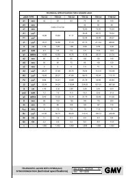
6.5 TABELLA DEI PARAMETRI DELL'OPERATORE<br />
PARAMETRI PORTE VICTORY – SCH<strong>ED</strong>A N 610 A r2 VERSIONE ATMEGA (vedi foglio dedicato abbinato all’operatore)<br />
COD. MIN. MAX. PAR.<strong>DI</strong> DEFAULT NOTE<br />
P0<br />
P1<br />
P2<br />
P3<br />
P4<br />
P5<br />
P6<br />
P7<br />
P8<br />
P9<br />
PA<br />
PB<br />
PC<br />
Velocità apertura<br />
Velocità chiusura<br />
Limite della forza in chiusura<br />
Velocità finale in apertura<br />
Velocità finale in chiusura<br />
Velocità rilascio pattino retrattile in apertura<br />
Forza di mantenimento porta aperta<br />
Forza di mantenimento porta chiusa<br />
Spazio sollevamento camme. Valore consigliato 14<br />
Tempo di accelerazione inizio apertura e inizio chiusura<br />
Non utilizzato<br />
Non utilizzato<br />
Selezione fotocellula<br />
0= esclusa 1= attiva 3= ritorno ai parametri di default<br />
15<br />
10<br />
10<br />
01<br />
01<br />
09<br />
01<br />
01<br />
00<br />
02<br />
-<br />
-<br />
00<br />
25<br />
25<br />
25<br />
15<br />
15<br />
15<br />
15<br />
15<br />
25<br />
10<br />
-<br />
-<br />
03<br />
PD<br />
Selezione di rallentamento<br />
1= corto 2= normale 3= lungo 4= molto lungo<br />
01<br />
04<br />
PE<br />
Spazio in bassa velocità per completamento apertura<br />
04<br />
25<br />
PF<br />
Spazio che anticipa l'informazione di porta chiusa da sommare a P8<br />
Con porta chiusa ossia relè K2 eccitata si escludono fotocellula<br />
e costola sensibile<br />
00<br />
25<br />
U0<br />
Forza massima chiusura. Per manovra fireman.<br />
Solo con EXF attivo.<br />
10<br />
25<br />
U1<br />
Ingresso (F1 - F2) 00= fotocellula esterna<br />
01= contatto porta chiusa<br />
00<br />
01<br />
U2<br />
Non utilizzato<br />
-<br />
-<br />
U3<br />
Selezione encoder. Valore U3=0 per encoder esterno; U3=1<br />
o 2 per encoder sul motore.<br />
N.B. Automaticamente il parametro U3 se è stato selezionato<br />
1 o 2 assumerà il valore corretto secondo il senso di apertura<br />
della porta.<br />
00<br />
02<br />
U4<br />
Automatismo di apertura fotoc e costola<br />
00=automatico 01= subordinato al quadro<br />
00<br />
01<br />
U5<br />
Non utilizzato<br />
-<br />
-<br />
U6<br />
Ritardo attivazione al l'accensione. In secondi<br />
00<br />
25<br />
9
I<br />
7. FASE <strong>DI</strong> ACQUISIZIONE:<br />
Se è necessario sostituire la scheda, o comunque si vuole ripetere l’acquisizione dell’apertura porta,<br />
procedere nel seguente modo:<br />
1 - Mettere l’operatore in condizione di poter lavorare senza azionare le porte del piano, con la possibilità<br />
di vedere il movimento delle camme.<br />
2 -Togliere tensione alla scheda scollegando JP1 e JP12 se vi è collegata la batteria. Portare le porte<br />
di cabina in posizione chiusa. Scollegare provvisoriamente JP11 per muovere più facilmente la porta.<br />
3 -Inserire il ponticello JP 2. Oppure premere il pulsante TA1 e tenerlo premuto fino a 20” dopo aver<br />
alimentato la scheda.<br />
4 -Alimentare la scheda collegando JP1. La porta si chiuderà completamente chiudendo le camme,<br />
e poi si riaprirà; da quel momento farà l’acquisizione dell’apertura. Togliere il ponticello JP2 e togliere<br />
l’alimentazione per alcuni secondi dalla scheda, l’operazione risulta così ultimata .<br />
5 -L’operazione di acquisizione può essere ripetuta.<br />
8. MESSA IN FUNZIONE E TEST:<br />
1 - Quando si alimenta la scheda, automaticamente il microprocessore ordina la chiusura.<br />
Indipendentemente dalla posizione della porta.<br />
2 - A porta chiusa dovrà essere acceso il Led FC ed il led DL1 (CK) potrà essere acceso o spento.<br />
9. SOSTITUZIONE RE<strong>ED</strong> E TENSIONAMENTO CINGHIA POLY VJ<br />
La posizione corretta della piastrina porta reed facilita il tensionamento della cinghia Poly VJ (cinghia<br />
nera). Vedi fig. 6.<br />
10. IN<strong>DI</strong>CAZIONI PER IL QUADRISTA<br />
10.1 OR<strong>DI</strong>NE <strong>DI</strong> APERTURA.<br />
Per l’apertura deve arrivare dal quadro un segnale negativo COM sul TAP.<br />
L’apertura completa è segnalata dal led D10 (verde) e dal L<strong>ED</strong> FA che indica l’eccitazione del relè K3.<br />
Raggiunta la completa apertura , si attiva una funzione che tende a mantenere la porta aperta .<br />
Se si tenta di chiudere le porte forzando le antine , l’operatore continua a riaprire le porte.<br />
L’ordine di apertura deve essere mantenuto fino all’eccitazione del relè K3<br />
10
I<br />
10.2 OR<strong>DI</strong>NE <strong>DI</strong> CHIUSURA :<br />
Per la chiusura deve arrivare dal quadro un segnale negativo COM sul TCP .<br />
Raggiunta la completa chiusura , si attiva una funzione di automantenimento che tiene la porta ben<br />
chiusa per evitare aperture involontarie dei contatti del blocco durante la marcia .<br />
Se durante la chiusura intervengono: fotocellula , costola sensibile o barriera ottica , si avrà L’eccitazione<br />
del relè K1 su connettore JP10 morsetto CAM. Mediante il parametro U4 si può decidere se con<br />
l’intervento del relè K1, la riapertura è eseguita in modo automatico dalla scheda oppure è subordinata<br />
al quadro di manovra.<br />
Nel corso della riapertura il relè K 1 rimane sempre eccitato.<br />
L’ordine di chiusura deve essere mantenuto fino alla completa chiusura dei blocchi, meglio se attivo<br />
durante la marcia dell’ascensore.<br />
10.3 COMANDO SEMPLIFICATO :<br />
Facendo il ponte sui morsetti JP 11, COM-TAP, ossia lasciando attivo l’ordine di apertura permanente,<br />
è possibile usare solo il comando di chiusura.<br />
In presenza di questo, la porta si chiude (poiché il segnale di chiusura ha la priorità sul segnale di<br />
apertura) e rimane chiusa, in assenza, si apre automaticamente.<br />
10.4 COMANDO APERTURA IN EMERGENZA - CONN.JP11:<br />
Per l’apertura di emergenza deve arrivare dal quadro un segnale negativo COM sul APE.<br />
Questo comando ha una priorità assoluta, se la scheda è alimentata normalmente, si esegue un' apertura<br />
normale, se invece è alimentata dalla batteria, si aziona il motore a piena tensione per 20” e dopo<br />
lo si lascia senza alimentatore.<br />
10.5 COMANDO ESCLUSIONE FOTOCELLULE - CONN.JP11:<br />
Se si esegue un collegamento tra i morsetti COM - EXF, il microprocessore ignora la fotocellula e<br />
la barriera ottica, ma non la costola sensibile. Questa sequenza è necessaria per soddisfare la manovra<br />
pompieri.<br />
11. POSIZIONE DELLA DELLA PIASTRINA CON IL RE<strong>ED</strong> IN CORRISPONDENZA<br />
DELLA PULEGGIA NERA<br />
15mm<br />
FIG. 6<br />
11
I<br />
Una volta verificata la posizione della piastrina con reed allentare la puleggia dalla parte opposta alla<br />
piastrina per allentare la cinghia dentata, una volta allentata la cinghia dentata scalzare la cinghia<br />
Poly Vj facendola scorrere con le mani. A questo punto è possibile la sostituzione della piastrina con<br />
il Reed.<br />
Per riposizionare la piastrina con il Reed nella posizione corretta eseguire le seguenti operazioni:<br />
posizionare la piastrina come indicato nella figura n° 6 e bloccarla con forza, inserire la cinghia Poly<br />
Vj facendola scorrere sulle pulegge, per ultimo riposizionare le cinghia dentata nella posizione d’origine.<br />
12. MANUTENZIONE<br />
Ad ogni intervento di manutenzione verificare i seguenti punti:<br />
· stato usura pattini<br />
· pulizia delle guide e delle soglie<br />
· eventuali danni alle ante<br />
· contatti elettrici<br />
· stato di pulizia delle rotelle di accoppiamento,di scorrimento e relative guide<br />
ATTENZIONE<br />
· non ingrassare ed oliare le guide<br />
· non ingrassare ed oliare le cinghie di trasmissione<br />
· non ingrassare ed oliare i cuscinetti delle ruote<br />
13. <strong>DI</strong>AGNOSTICA E CONTROLLI<br />
La scheda N610 A r2 mediante dei led luminosi permette di verificare il corretto funzionamento<br />
dell’operatore nelle sue funzioni.<br />
Troverete qui di seguito le principali descrizioni dei singoli led luminosi e le eventuali azioni da effettuare<br />
nel caso in cui si presentino anomalie nel funzionamento dell’operatore.<br />
· Scollegare il connettore JP6 (alimentazione motore).<br />
· Aprire manualmente le porte di cabina con lo scivolo totalmente aperto<br />
13.1 VERIFICHE FUNZIONAMENTO RE<strong>ED</strong>.<br />
A fine apertura verificare che il led D10 (verde)ed il led FA (rosso) siano accesi, in questo caso il reed<br />
di porta aperta funziona correttamente. A fine apertura normalmente il L<strong>ED</strong> D10 e FA sono accesi.<br />
Se questo non accade, avvicinare un magnete al reed. Se il L<strong>ED</strong> D10 si accende verificare la posizione<br />
della calamita sulle cinghie. Se il L<strong>ED</strong> non si accende sostituire il reed.<br />
13.2 VERIFICA FUNZIONAMENTO LETTORE ENCODER.<br />
Per verificare il funzionamento del lettore encoder muovere molto lentamente le ante e controllare<br />
che il led DL1 (rosso) lampeggi. Nel caso in cui non lampeggia deve essere sostituito l’encoder con<br />
relativo motore.<br />
IN CASO <strong>DI</strong> INCERTEZZE O DUBBI CONTATTATE UN NOSTRO TECNICO.<br />
12
EN<br />
Thank you for choosing GMV S.p. .A<br />
In order to ensure your system the best running conditions throughout time, we invite<br />
you to read these instructions carefully. Furthermore, this manual should be kept with the<br />
system it is dedicated to for any possible future interventions.<br />
FOREWORD:<br />
This manual has been drafted with the assumption that the companies which will be in charge<br />
of installing the GMV products comply with the following requirements:<br />
· The personnel appointed to the installation and/or maintenance of the doors is aware of<br />
the general and specific standards in force as regards safety and hygiene on the workplace<br />
(391/89/UE – 654/89/UE – 656/89/UE)<br />
· The personnel appointed to the installation and/or maintenance is trained on GMV<br />
products either directly by GMV or by a dealer who has already been trained on the<br />
product.<br />
· The assembly equipment used is efficient and the measure instruments are under control<br />
(655/89/UE)<br />
This manual is supplied with the GMV product and – subsequently – it will be updated<br />
with the product it refers to; therefore, it has to be kept with the specific operator, since it is to<br />
be considered as dedicated to it. The use of non-dedicated documentation can be considered<br />
inappropriate. Refer to the system number on the manual.<br />
GMV S.p.A. The information contained in this manual may be modified without notice.<br />
GMV S.p.A. cannot be held liable for any injuries or damage due to inaccuracy and/or<br />
wrong interpretations of the manual’s contents.<br />
1. NOTE<br />
The GMV op eret or whit en coder group represents a new concept of lift door operator, studied to reduce<br />
to a minimum the assembly and adjustment time.<br />
Its simple and flexible structure makes it suitable for both new installations and modernizations.<br />
The system consists of the following parts:<br />
A- DC motor operator c/w reduction gear and belt transmission.<br />
B- Encoder assembly to provide the incremental door position and the ‘door open’ information.<br />
C- Microprocessor control card to control both the motor driver and the logic assembly operation.<br />
D- Microprocessor control card for motor drive.<br />
The arrangement diagram (See figure 4) shows the structure of the system.<br />
13
EN<br />
2. OPERATOR INSTALLATION<br />
The operator is delivered pre-wired and tested (subsequently, the door light does not need to<br />
be acquired) in order to simplify installation. The operator’s package includes the screws and<br />
brackets as required for assembly. Unless they are specifically requested, the supply does not<br />
include the car sill, car parameter or the programming keyboard.<br />
1. Attach the brackets to the operator as shown in Fig. 1.<br />
2. Attach the operator through the brackets located on the booth roof and align it to the car sill.<br />
Thoroughly tighten the attachment bolts (See figure 2).<br />
FIG. 1<br />
H=2185<br />
160<br />
60<br />
H=2185<br />
160<br />
60<br />
H=2000<br />
H=2000<br />
min 30<br />
min 30<br />
CAR SILL LINE<br />
65<br />
CAR SILL LINE<br />
5<br />
40 40<br />
H=0<br />
41<br />
H=0 41<br />
35<br />
SCREW M10 20<br />
34<br />
75<br />
750 35<br />
SCREW M10<br />
52<br />
90<br />
750<br />
FIG. 2<br />
14
EN<br />
3. Attachment of the car wings. After attaching the car wings (see Figure 3), check the space between<br />
the wings and the car shoulder and between the sill and the small wing (see Figure 2). Should the<br />
space not be correct (5 mm) use the purposely allocated shims to set the wings into the right position.<br />
FIG. 3<br />
15
EN<br />
3. SCHEME ENCODER<br />
FIG. 4<br />
16
EN<br />
4. CONNECTIONS<br />
Refer to the general diagram (figure 4)<br />
4.1 CONNECTION JP<br />
- Connector JP 1 (L1 – L2)<br />
Card power supply.<br />
Observe the following polarities:<br />
L1 positive; insert the ferrites ; L2 negative ; insert the ferrites;<br />
Power supply transformer 24 V ac – 140 VV<br />
Rectifier 26MB60 or similar.<br />
(We recommend the introduction of a 50V – 2200 F electrolytic capacitor. See diagram on Figure 4).<br />
- Connector JP 2<br />
Jumper used to detect door opening acquisition. As an alternative, use push-button TA1. (See<br />
acquisition cycle – item 7).<br />
- Connector JP3<br />
Connection for the serial communication with the operation panel.<br />
- Connector JP 4<br />
Connection of programming keyboard.<br />
USE: refer to the section describing the modification of parameters. (item 6).<br />
- Connector JP 5<br />
Connection reserved to micro-processor programming.<br />
Not useful for the user.<br />
- Connector JP 6 (M1 - M2)<br />
Door-motor power supply. The position of the motor wires versus the connector is not preliminarily<br />
established, it depends on the door opening side.<br />
- Connector JP 7 (P1 – P2; R1 – R2)<br />
Photocell management<br />
Connect as follows:<br />
P1 Projector TX screen (Grid) -P1 (Attention: 5 V positive)<br />
P2 TX red cable<br />
R1 Receiver RX transparent cable<br />
R2 RX sceen (Grid) -R2 (Attention: 24 V positive)<br />
The RX TX of Company OPTEA PRS 103 is usually used.<br />
- Connector JP 8 (F1 – F2)<br />
Double function input:<br />
parameter U1=00 optic barrier input (contact NA)<br />
parameter U1=01 input of the end of closing contact.<br />
Normally U1=00.<br />
17
EN<br />
- Connector JP 9 (ENCODER)<br />
The microprocessor card is connected to the encoder card by means of a pre-packed cable. It also<br />
carries the door close information (to be used for external encoder only).<br />
- Connector JP 10 (FCA – FCC – CAM)<br />
Output of the following information on the NC contacts for the operation panel:<br />
1 - Opening limit switch terminals 1 and 2 - FCA<br />
2 - Closing limit switch terminals 3 and 4 - FCC<br />
3 - Photocell or sensitive edge intervention terminals 5 and 6 - CAM<br />
- Connector JP 11 (TAP – TCP – EXF – APE – COM)<br />
Door Opening/Closing Management<br />
1 - Opening instruction from the panel terminal / TAP<br />
2 - Closing instruction from the panel terminal / TCP<br />
3 - Instruction of photocell by-pass for firemen intervention terminal / EXF<br />
4 - Emergency opening instruction terminal / APE<br />
5 - Negative in output (24 Volts) terminal / COM<br />
The instructions are activated by connecting the terminals to negative<br />
COM<br />
- Connector JP12<br />
Output for 24V - 1.2A battery.<br />
Observe the following polarities:<br />
terminal + positive;<br />
terminal - negative;<br />
The card will charge this battery Vc:27.4V Ic:200mA<br />
.- Connector JP 15 (GONG)<br />
Gong output<br />
A loudspeaker of 8 ohm impedance can be connected.<br />
The GONG potentiometer enables to the tonality of the gong, but not its volume. (The GONG monitors<br />
the opening of the doors).<br />
- Connector JP 16 (CPA)<br />
Connection for reed FA. (end of opening) for operator motor with incorporated encoder.<br />
- Connector JP 17 (ENC.M)<br />
Connection for encoder incorporated to the motor.<br />
4.2 DESCRIPTION OF THE L<strong>ED</strong>’S<br />
- L<strong>ED</strong> D10 – Green<br />
Indicates the closing of the reed contact which detects the door open status.<br />
- L<strong>ED</strong> DL1 – (CK) Red<br />
Indicates the operation of the encoder. Channel A.<br />
During the standard operation, it blinks at high frequency at looks as if it were permanently lit-<br />
When the door is stopped, it can indifferently lit or unlit.<br />
- L<strong>ED</strong> FA – Red<br />
It signals the activation of relay K3, which means the complete opening of the door.<br />
- L<strong>ED</strong> FC – Red<br />
It signals the activation of relay K2, which means the complete closing of the door.<br />
18
EN<br />
- L<strong>ED</strong> CM – Red<br />
It signals the activation of relay K1, which means the intervention of either the photocell or the sensitive<br />
edge.<br />
- L<strong>ED</strong> DL5 – Yellow<br />
Micro power supply effective (5V).<br />
- L<strong>ED</strong> DL6 – Red<br />
MOSI Serial communication.<br />
- L<strong>ED</strong> DL7 – Red<br />
SCK serial communication.<br />
- Fuse F1<br />
It protects the card from short-circuits.<br />
Use 4 AMP quick fuses.<br />
5. OPERATIONAL DESCRIPTION<br />
By a simple operation of data acquisition made at GMV factory, which can be easily repeated<br />
on site, the microprocessor – through an encoder – measures and acquires the length of the door,<br />
with accuracy within millimeters.<br />
The measure of the free door width is stored into a retention memory areas (ROM) and it is not<br />
cancelled if the power supply to the card is interrupted.<br />
A programming keyboard, which is supplied separately, allows varying the parameters to adapt them<br />
at the best to the specific operational conditions.<br />
The operator is supplied factory tested and adjusted, subsequently, no acquire operations are required<br />
on site.<br />
6. ADJUSTMENT OF PARAMETERS<br />
6.1 ADJUSTMENT OF PARAMETERS<br />
The operation of the control card for the operator is based on a series of internal variables (the socalled<br />
parameters) that are preliminarily adjusted in the workshop, but can be modified during<br />
installation in order to adapt the operator to the features of the lift.<br />
Normally, no adjustment is required, because the values are installed and stored at the factory.<br />
If a different adjustment is needed because of special requirements, customerization is carried out<br />
with a programming keyboard to be used as follows:<br />
· Connect the programming keyboard to the card on connector JP 4.<br />
· Move the sliding switch to position PROGRAMMING (P); the display shows the code of the first<br />
parameter (P.0) for a few seconds, and then its value on two digits.<br />
· If the modification concerns P.0, press the push-buttons (+) to increment or (-) to decrement its<br />
value.<br />
· If the modification concerns another parameter, press push-button (S) until the code of the required<br />
one is displayed.<br />
· Now press push-buttons (+) or (-) until the required value is obtained; it is automatically stored and<br />
then it will become operational.<br />
· The push-button (T) TEST carries out a door opening or closing cycle (depending on its position)<br />
in order to check that all adjustments give the expected result.<br />
19
EN<br />
PROGRAMMING KEYBOARD<br />
KEYBOARD<br />
(+)<br />
(T) (S)<br />
(-)<br />
SLI<strong>DI</strong>NG SWITCH<br />
(P)<br />
Programming<br />
(N)<br />
Regular<br />
6.2 RESET OF THE INITIAL PARAMETERS<br />
In order to take the operator control card back to the initial parameters, introduce the programming<br />
keyboard, set the sliding switch on (P) and then take parameter PC to 03. Then, take the sliding<br />
switch back on (N), so that the card acquires again the values which were initially set up by GMV<br />
(factory Default parameters) If they have not been modified, see below.<br />
6.3 MO<strong>DI</strong>FICATION OF THE DEFAULT PARAMENTERS<br />
GMV'original parameters may need to be modified in order to obtain an operation which is<br />
more tuned to the requirements of the system. After having modified the parameters, they can be<br />
stored as default. To store them, carry out the following operations: disconnect connector JP1 (power<br />
supply), connect the programming keyboard with the switch on N (normal) press keys T and S at the<br />
same time, reconnect JP1, always holding the keys down at wait until the keyboard displays four<br />
vertical bars, The program codes shall be displayed again once the operation is complete. At the end<br />
of this operation, the parameters set shall be the default ones, which can always be restored by means<br />
of the process we described above. (See section 6.2)<br />
6.3 SUMMARY OF THE FUNCTIONS<br />
(S) Parameter selection from P.0 to PF<br />
(+) Increases the parameter value up to a maximum of 25<br />
(-) Decreases the parameter value<br />
(T) TEST Testing cycle; the door is opened or closed according to its status<br />
(P) PROGRAMMING POSITION<br />
(N) RUNNING POSITION<br />
Remark: THE KEYBOARD CONNECTOR IS TO BE PLUGG<strong>ED</strong> AND/OR UNPLUGG<strong>ED</strong> WITHOUT CARD POWER<br />
SUPPLY ON TERMINAL. THE KEYBOARD MUST NOT BE LEFT CONNECT<strong>ED</strong> TO THE CARD DURING THE CARD<br />
DURING THE NORMAL OPERATION.<br />
T<br />
+<br />
-<br />
S<br />
P<br />
N<br />
FIG.5<br />
20
EN<br />
6.5 TABLE OF OPERATOR PARAMETERS<br />
VICTORY DOORS PARAMETERS - CARD N 610 A r2 - VERSION ATMEGA (See dedicated sheet associated to the operator)<br />
COD. MIN. MAX. PAR.<strong>DI</strong> DEFAULT NOTE<br />
P0<br />
P1<br />
P2<br />
P3<br />
P4<br />
P5<br />
P6<br />
P7<br />
P8<br />
P9<br />
PA<br />
PB<br />
Opening speed<br />
Closing speed<br />
Limit of closing force - voltage<br />
Final opening speed<br />
Final closing speed<br />
Release speed of retractable shoe during opening<br />
Open door holding force<br />
Close door holding force<br />
Cam lifting space. Recommended value 14<br />
Acceleration time at opening/closing beginning<br />
Not used<br />
Not used<br />
15<br />
10<br />
10<br />
01<br />
01<br />
09<br />
01<br />
01<br />
00<br />
02<br />
-<br />
-<br />
25<br />
25<br />
25<br />
15<br />
15<br />
15<br />
15<br />
15<br />
25<br />
10<br />
-<br />
-<br />
PC<br />
Photocell selection<br />
0= off 1= active 3= return to the default parameters<br />
00<br />
03<br />
PD<br />
Slow-down space<br />
1= short 2= normal 3= long 4= very long<br />
01<br />
04<br />
PE<br />
Distance covered at low speed to complete opening<br />
04<br />
25<br />
PF<br />
Space which anticipates the door closed information.<br />
To be added to P8 With door closed - i.e. relay K2 energized -<br />
the photocell and sensitive edge are by-passed.<br />
00<br />
25<br />
U0<br />
Maximum closing force.<br />
In case of fire, with EXF "ON"<br />
10<br />
25<br />
U1<br />
Input (F1 - F2)<br />
00= external photocell<br />
01= door closed contact<br />
00<br />
01<br />
U2<br />
NOT used<br />
-<br />
-<br />
U3<br />
Encoder selection. Value U3=0 for external encoder;<br />
U3=1 or 2 for encoder on motor.<br />
Remark: If 1 or 2 selected parameter U3 shall take the corret<br />
value according to the door opening direction.<br />
00<br />
02<br />
U4<br />
Photocell and edge opening automatism<br />
00=automatic 01= depending on the panel<br />
00<br />
01<br />
U5<br />
NOT used<br />
-<br />
-<br />
U6<br />
Delay in power up. In seconds<br />
00<br />
25<br />
21
EN<br />
Example on operator with LH opening<br />
7. DATA ACQUISITION STAGE<br />
To replace the card, or in any case to repeat the door width measurement, proceed as follows:<br />
1 - The operator shall be in the condition to work without operating the landing doors; the cam<br />
movement shall be visible.<br />
2 - Cut off the power to the card by disconnecting JP1 (and JP12 if the battery is conncted). Move<br />
the car doors to closed position. Disconnect JP11 to move the door more easily.<br />
3 - Introduce jumper JP 2. Otherwise, press push-button TA1 and hold it pressed for 20” after powering<br />
the card.<br />
4 - Connect JP1from card power supply. The door shall close completely closing the cams and then<br />
it will open again; from that moment it will acquire the opening. Disconnect jumper JP2 and remove<br />
power supply to the card for a few seconds. The operation is then complete.<br />
5 - The acquire operation can be repeated.<br />
8. COMMISSIONING AND TESTING<br />
1 - When the card receives power supply, the microprocessor shall immediately command closing,<br />
irrespectively on what the position of the door is.<br />
2.- When the door is closed, Led FC shall be lit and L<strong>ED</strong> DL1 (CK) may be either lit or unlit.<br />
9. REPLACEMENT OF THE RE<strong>ED</strong> AND TIGHTENING OF BELT POLY VJ<br />
The correct position of the reed holding plate facilitates tightening of belt Poly VJ (black).<br />
See Figure 6.<br />
10. IN<strong>DI</strong>CATIONS FOR THE CONTROL PANEL OPERATOR<br />
10.1 OPENING COMMAND<br />
For opening, the control panel has to send a signal of negative COM on TAP.<br />
The complete opening is pointed out by L<strong>ED</strong> D10 (green) and by L<strong>ED</strong> FA which indicated that relay<br />
K3 is energized.<br />
Once the complete opening is reached, a function activates to keep the door open.<br />
If one tries to close the doors by forcing the wings, the operator will keep on closing the doors.<br />
The opening command is to be kept until relay K3 is energized.<br />
22
EN<br />
10.2 CLOSING COMMAND<br />
For closing, the control panel has to send a signal of negative COM on TCP<br />
Once the complete closing is achieved, a self-maintaining circuit is activated to keep the door well<br />
closed in order to avoid any unintentional opening of the block during the running.<br />
Should the photocell, the sensitive edge or the optic barrier be triggered during closing, there will be<br />
the energizing of relay K1, connector JP10 terminal CAM. Parameter U4 enables to decide if the<br />
opening after the sensitive edge is triggered is automatic or subordinate to the control panel WITH<br />
the intervention of relay K1.<br />
The closing command is to be kept up to the complete closing of the blocks, better if it is active during<br />
the running of the elevator.<br />
10.3 SIMPLIFI<strong>ED</strong> COMMAND<br />
By jumping terminals JP 11, COM-TAP, i.e. leaving active the command of permanent opening, the<br />
sole closing command can be used.<br />
In its presence, the door closes (since the closing signal has priority over the opening one) and remains<br />
closed. I its absence, it opens automatically.<br />
10.4 EMERGENCY DOOR OPENING COMMAND - CONN. JP 11<br />
For emergency opening, the control panel is to receive a negative COM signal on APE.<br />
This instruction has absolute priority. If the card is normally supplied, a standard opening shall be<br />
carried out. If, on the other hand, it is supplied from the battery, the motor shall be operated at full<br />
voltage for 20” and then it is left without supply.<br />
10.5 PHOTOCELL BY-PASS COMMAND - CONN. JP 11<br />
If a connection is carried out between terminals COM - EXF, the microprocessor shall ignore the<br />
photocell and the optic barrier, but not the sensitive edge. This is the sequence required to meet the<br />
firemen operation requirements.<br />
11. POSITION OF THE PLATE WITH THE RE<strong>ED</strong> IN CORRESPONDENCE<br />
OF THE BLACK PULLEY.<br />
15mm<br />
FIG.6<br />
23
EN<br />
Once the position of the plate with reed is ascertained, loosen the pulley from the opposite side to<br />
the plate to loosen the toothed belt. Once the belt is loose, extract belt Ply Vj by sliding it manually.<br />
Then, the plate with the Reed can be replaced.<br />
Proceed as follows to relocate the plate with the Reed into the correct position: locate the card as<br />
shown in figure 6 and tighten it thoroughly, insert belt Ply Vj sliding it on the pulleys, at the en put the<br />
toothed belt back to the original position.<br />
12. MAINTENANCE<br />
At every maintenance intervention, check the following:<br />
· Wear of the shoes<br />
· Cleanness of lines and ways<br />
· Any damage to the wings<br />
· Electric contacts<br />
· Cleanness of the mating and sliding wheels, and relevant guideways.<br />
WARNING<br />
· Do not lubricate the guideways<br />
· Do not lubricate the transmission belts<br />
· Do not lubricate the wheel bearings<br />
13. <strong>DI</strong>AGNOSTIC AND CHECKS<br />
By means of L<strong>ED</strong>’s, card N610 A r2 enables to check the correct operation of the operator in its<br />
functions.<br />
You will find hereinunder the main descriptions of the different L<strong>ED</strong>’s and the actions which can be<br />
undertaken in case of operator’s failures.<br />
· Disconnect connector JP6<br />
· Manually open the car doors with a fully opened slide<br />
13.1 CHECKS ON THE OPERATION OF THE RE<strong>ED</strong><br />
At the end of the opening, make sure that L<strong>ED</strong>’s D8 (green) and FA (red) are lit; in this case, the reed<br />
of card N13 is operating correctly. At the end of the opening, L<strong>ED</strong>’s D10 and FA are normally lit.<br />
Should this not be the case, move a magnet close to the reed. If L<strong>ED</strong> D10 lights, ascertain the position<br />
of the magnet on the belts. Replace the reed if the L<strong>ED</strong> does not light.<br />
13.2 CHECKING OF THE ENCODER READER OPERATION<br />
In order to ascertain the operation of the encoder, move the door wings very slowly and make sure<br />
that L<strong>ED</strong> DL1 (red) is blinking. If it does not blink, replace the encoder and the relevant motor.<br />
ADDRESS OUR ENGINEERS IN CASE OF ANY DOUBTS<br />
24
D<br />
Wir danken Ihnen, dass Sie sich für die Produkte der GMV S.p. .A. entschieden haben.<br />
Bitte lesen Sie die nachfolgenden Hinweise sorgfältig durch und bewahren Sie dieses<br />
Handbuch für eventuelle künftige Arbeiten bei der Anlage auf.<br />
VORWORT:<br />
Dieses Handbuch wurde unter der Voraussetzung erstellt, dass die Installateure dieses Produktes<br />
der Fa. GMV den folgenden Anforderungen genügen:<br />
· Dem Installations- bzw. Wartungspersonal der Türen sind die gültigen allgemeinen und<br />
spezifischen Vorschriften für die Arbeitssicherheit und -hygiene (391/89EG – 654/89/EG –<br />
656/89/EG) bekannt.<br />
· Das Installations- bzw. Wartungspersonal der Türen ist mit dem Produkt GMV vertraut<br />
und wurde entweder von GMV selbst oder von einem Händler geschult, der das<br />
Produkt gut kennt.<br />
· Das verwendete Montagewerkzeug muss einwandfrei sein und die Messinstrumente sind<br />
regelmäßig zu kontrollieren (655/89/EG).<br />
Das vorliegende Handbuch wird dem Produkt von GMV beigelegt und entspricht immer<br />
dem neuesten Stand. Es ist wichtig, dass die Dokumentation jedem einzelnen Türantrieb beigelegt<br />
wird, weil sie hierfür spezifisch anzusehen ist. Die Verwendung eines nicht für diesen Antrieb<br />
bestimmten Handbuchs ist nicht zulässig. S. Handbuch Nr. ……..<br />
GMV S.p. .A.: Sämtliche Angaben in diesem Handbuch können ohne weitere Benachrichtigung<br />
geändert werden. GMV S.p. .A. haftet nicht für Personen- oder Sachschäden auf Grund<br />
unsachgemässer oder falscher Deutung des Inhalts.<br />
1. EINLEITUNG<br />
Tü rant rieb GMV m it encoder ist ein Antrieb für Aufzugstüren, das zur Reduzierung der Montageund<br />
Installationszeiten entwickelt wurde.<br />
Durch seine einfache und flexible Struktur ist es sowohl für den Neubau als auch für Renovierungen<br />
geeignet.<br />
Das System besteht aus den folgenden Teilen:<br />
A - Türantrieb mit Gleichstrommotor und Riemenantrieb.<br />
B - Inkrementalgeber für die Wegmessung der Tür und der Endstellung ‚Tür offen’.<br />
C - Reed-Kontakt: er übermittelt der Steuerkarte die Information, dass die Tür offen ist.<br />
D - Mikroprozessor-Steuerplatine für den Motorantrieb.<br />
Aus dem Lageplan (s. Abb. 4) kann der Systemaufbau entnommen werden.<br />
25
D<br />
2. MONTAGE DES ANTRIEBS<br />
Der Antrieb wird vorverkabelt geliefert und getestet (keine Lernfahrt der Türbreite erforderlich),<br />
um den Installationsaufwand zu reduzieren.<br />
In der Verpackung sind die für die Montage erforderlichen Schrauben und Bügel bereits enthalten.<br />
Dagegen sind Fotozelle, Kabinenschwelle, Kabinenschürze und Programmiergerät im Lieferumfang<br />
nicht enthalten, wenn nicht ausdrücklich bestellt.<br />
1. Haltewinkel am Antrieb wie in Abb. 1 befestigen:<br />
ABB. 1<br />
2. Türantrieb mit den Winkeln am Kabinendach befestigen und an der Kabinenschwelle ausrichen.<br />
Anschließend verschrauben (s. Abb. 2).<br />
H=2185<br />
160<br />
60<br />
H=2185<br />
160<br />
60<br />
H=2000<br />
H=2000<br />
min 30<br />
min 30<br />
KANTE KABINENSCHWELLE<br />
65<br />
KANTE KABINENSCHWELLE<br />
5<br />
40 40<br />
H=0<br />
41<br />
H=0 41<br />
35<br />
SCHRAUBE M10 20<br />
34<br />
75<br />
750 35<br />
SCHRAUBE M10<br />
52<br />
90<br />
750<br />
ABB. 2<br />
26
D<br />
3. Befestigung der Kabinentürblätter. Nach der Befestigung der Kabinentürblätter (siehe Abb. 3)<br />
muss der Abstand zwischen den Blättern und zwischen Schwelle und Türblatt (s. Abb. 2) überprüft<br />
werden. Sind die Abstände nicht korrekt (5 mm), die dafür vorgesehenen offenen Beilagbleche<br />
verwenden und die Türflügel richtig positionieren.<br />
ABB. 3<br />
27
D<br />
3. ENCODERPLAN<br />
ABB. 4<br />
28
D<br />
4. ANSCHLÜSSE<br />
4.1<br />
Siehe Platinenplan Abb. 4.<br />
- Steckverbinder JP 1 (L1 – L2)<br />
Einspeisung Platine.<br />
Die angegebenen Polaritäten sind zu beachten:<br />
L1 positiv; Ferritkern umwickeln L2 negativ; Ferritkern umwickeln<br />
Einspeisetrafo 24VAC~ – 140VA, gleichgerichteter Wechselstrom (nicht im Victory Doors<br />
Lieferumfang enthalten)<br />
Gleichrichter Typ 26MB60 o. ä.<br />
(Wir empfehlen, ein Elektrolytkondensator 50V – 2200 F zu verwenden. S. Abb. 4).<br />
- Steckverbinder JP 2<br />
Brücke zum Erlernen der Türöffnung. Als Alternative kann der Drucktaster TA1 verwendet werden.<br />
(S. Lernfahrt Punkt 7).<br />
- Steckverbinder JP 3<br />
Anschluss für den seriellen Datenaustausch mit der Steuerung.<br />
- Steckverbinder JP 4<br />
Anschluss für das Programmiergerät<br />
Hinweise für den Einsatz entnehmen Sie bitte dem Abschnitt über die Parameteränderung (Punkt 6)<br />
- Steckverbinder JP 5<br />
Anschluss für die Programmierung des Mikroprozessors.<br />
Nicht für den Anwender.<br />
- Steckverbinder JP 6 (M1 – M2)<br />
Stromversorgung Türmotor. Die richtige Polung der Zuleitung zum Motor kann nicht im Voraus<br />
bestimmt werden. Diese hängt von der Öffnungsrichtung der Tür.<br />
- Steckverbinder JP 7 (P1 – P2 ; R1 – R2)<br />
Anschluss Fotozellen.<br />
Sender und Empfänger der Fotozelle sind wir folgt anzuschließen:<br />
P1 Sender (TX) Schirm P1 (Achtung! positiv 5V)<br />
P2 Sender (TX) rot<br />
R1 Empfänger (RX) farblos<br />
R2 (RX) Schirm R2 (Achtung! positiv 24V)<br />
Normalerweise wird das Paar RX TX der Fa. OPTEA PRS 103 verwendet.<br />
- Steckverbinder JP 8 (F1 – F2)<br />
Eingang mit Doppelfunktion:<br />
mit Parameter U1=00 Eingang Lichtgitter (contatto NA - Kontakt)<br />
mit Parameter U1=01 Eingang Kontankt Schliessende.<br />
Normalerweise U1=00.<br />
29
D<br />
- Steckverbinder JP 9 (ENCODER)<br />
Verbindung Encoderplatine und Türsteuerungsplatine mittels vorkonfektioniertem Kabel. Sie trägt<br />
auch die Information für geschlossenen Tür (nur bei externem Encoder).<br />
- Steckverbinder JP 10 (FCA – FCC – CAM)<br />
Ausgänge an NC-Kontakten (normal geschlossen) für die folgenden Informationen an die Steuerung:<br />
1 -Endschalter Tür auf Klemme 1 und 2 – FCA<br />
2 -Endschalter Tür zu Klemme 3 und 4 – FCC<br />
3 - Ansprechen Fotozelle oder Schließkraftbegrenzung Klemme 5 und 6 – CAM<br />
- Steckverbinder JP 11 (TAP – TCP – EXF – APE – COM)<br />
Steuerung zum Tür öffnen und Tür schliessen<br />
1 - Öffnungsbefehl von der Steuerung Klemme / TAP<br />
2 - Schließbefehl von der Steuerung Klemme / TCP<br />
3 - Fotozelle wirkungslos wegen Feuerwehrfahrt Klemme / EXF<br />
4 - Türöffnungsbefehl bei Notfahrt Klemme / APE<br />
5 - Negativ am Ausgang (24 Volts) Klemme / COM<br />
Die Befehle werden durch Anschluss der Klemme<br />
an das negative Signal eingeschaltet COM<br />
- Steckverbinder JP 12 – ( + - )<br />
Batterieanschluss 24V – 1.2A.h<br />
Die Polarität muss unbedingt beachtet werden:<br />
Klemme + Positiv; Klemme – Negativ;<br />
Die Platine lädt diese Batterie mit 27,4 V Ic=/200 mA auf.<br />
- Steckverbinder JP 15 (GONG)<br />
Gong-Ausgang.<br />
Es kann ein Lautsprecher mit einer Impedanz von 8 Ohm angeschlossen werden.<br />
Das Potentiometer GONG ermöglicht die Einstellung der Gong-Klangfarbe, nicht der Lautstärke.<br />
(Der Gong ertönt, wenn die Tür beginnt aufzulaufen).<br />
- Steckverbinder JP 16 (CPA)<br />
Anschluss für Reed-Kontakt FA. (Öffnungsende) für Bediengerät mit eingebautem Motor und<br />
Encoder.<br />
- Steckverbinder JP 17 (ENC.M)<br />
Anschluss für im Motor eingebauten Encoder.<br />
4.2 BESCHREIBUNG L<strong>ED</strong><br />
- L<strong>ED</strong> D10 – Grün<br />
Zeigt die Schliessung des Reed-Kontakts, die auf den Zustand ‘offene Tür’ deutet.<br />
- L<strong>ED</strong> DL1 – (CK) Rot<br />
Zeigt die Encoderfunktion. Kanal A.<br />
Während der Türbewegung flackert die L<strong>ED</strong> mit hoher Frequenz.<br />
Bei geschlossener Tür kann die L<strong>ED</strong> in Abhängigkeit der Position des Encoders leuchten oder<br />
nicht leuchten.<br />
30
D<br />
- L<strong>ED</strong> FA - rot<br />
Zeigt die Erregung des Relais K3 und Tür vollständig geöffnet an.<br />
- L<strong>ED</strong> FC - rot<br />
Zeigt die Erregung des Relais K2 und Tür vollständig geschlossen an.<br />
- L<strong>ED</strong> CM - rot<br />
Zeigt die Erregung des Relais K1 und die Unterbrechung Fotozelle, Betätigung Schließkraftbegrenzung<br />
an.<br />
- L<strong>ED</strong> DL5 – Gelb<br />
Versorgung des Mikroschalters leistungsfähig (5V).<br />
- L<strong>ED</strong> DL6 – Rot<br />
Serieller Datenaustausch MOSI.<br />
- L<strong>ED</strong> DL7 – Rot<br />
Serieller Datenaustausch SCK.<br />
- Sicherung F1: Schützt die Platine vor eventuellen Kurzschlüssen. Flinke Sicherung mit 4 A<br />
verwenden.<br />
5. FUNKTIONSBESCHREIBUNG<br />
5.1 FUNKTION<br />
Mit einer von GMV durchgeführten, aber auch bei der Montage einfach zu wiederholendem<br />
Verfahren misst und lernt der Mikroprozessor mittels eines Messgebers die Türbreite mit Genauigkeit<br />
auf den Millimeter.<br />
Die Messung der freien Türbreite wird in einem spannungsabfallsicheren ROM-Speicherplatz hinterlegt.<br />
Mit dem Programmiergerät können die Parameter geändert werden, um sie den jeweiligen<br />
Arbeitsbedingungen anzupassen.<br />
Das Bediengerät wird werkseitig getestet und eingestellt: Die Lernfahrt auf der Baustelle ist nicht<br />
erforderlich.<br />
6. PARAMETER<br />
6.1 PARAMETEREINSTELLUNG<br />
Die Platine arbeitet mit internen Variablen (die sogenannten Parameter), die im Werk voreingestellt<br />
worden sind, aber während der Installation geändert werden können, um die Funktion des<br />
Bediengeräts an die individuellen Anlagenbedingungen anzupassen.<br />
Normalerweise ist es nicht notwendig, die Werkseinstellung zu verändern.<br />
Ist bei Bedarf eine andere Einstellung notwendig, erfolgt die individuelle Anpassung mit dem<br />
Programmiergerät:<br />
- Programmiergerät am Steckverbinder JP 4 der Platine anschließen<br />
- Schiebeschalter auf PROGRAMMIERUNG (P) schalten; auf dem Display wird die Abkürzung<br />
des ersten Parameters (P.0) einige Sekunden lang angezeigt, danach sein zweistelliger Wert<br />
- Sie ändern P.0 durch Drücken der Tasten (+) und (-)<br />
- Sie wechseln zum nächsten Parameter, indem Sie die Taste (S) drücken<br />
- Ändern Sie ihn mit den Tasten (+) bzw. (-); danach wird der Wert operativ.<br />
31
D<br />
Die Taste (T) TEST führt einen Öffnungs- bzw. Schließzyklus der Tür aus (je nach Türposition),<br />
um zu kontrollieren, ob die Einstellungen das gewünschte Ergebnis erzielen.<br />
PROGRAMMIERGERÄT<br />
TASTENFELD<br />
(+)<br />
(T) (S)<br />
(-)<br />
SCHIEBESCHALTER<br />
(P)<br />
Programmierung<br />
(N)<br />
Normal<br />
6.2 WI<strong>ED</strong>ERHERSTELLUNG DER DEFAULT-PARAMETER<br />
Um die gespeicherten Default-Parameter (Werksparameter) zu laden, das Programmiergerät<br />
einschalten, den Schiebeschalter auf (P) stellen, dann den Parameter PC auf den Wert 03 einstellen<br />
und danach den Schiebeschalter auf (N) zurückstellen, wenn sie nicht geändertt wurden –<br />
s. unten.<br />
6.3 ÄNDERUNG DER DEFAULT-PARAMETER.<br />
Es könnten erforderlich sein, die Default-Parameter von GMV zu ändern, um die Funktion<br />
des Bediengeräts an die individuellen Anlagenbedingungen anzupassen. Nachdem die Parameter<br />
geändert wurden, können sie als Default gespeichert werden. Um die Parameter zu speichern,<br />
gehen Sie wie folgt vor: Den Steckverbinder JP1 (Einspeisung) trennen; das Programmiergerät<br />
mit dem Schiebeschalter auf N (normal) anschließen und gleichzeitig die Taster T und S drücken,<br />
JP1 bei gedrückten Tastern wiederanschliessen und warten auf die Anzeige von vier vertikalen<br />
Stangen auf dem Bildschirm des Programmiergeräts. Danach erscheinen die<br />
Programmkennnummern. Anschließend werden die eingestellten Parameter den Default-<br />
Parameter entsprechen und können immer mit der beschriebenen Prozedur wiederhergestellt<br />
werden.(s. 6.2)<br />
6.4 ÜBERSICHT DER TASTEN<br />
(S Wahl der Parameter P.0 bis PF und U0 bis UF<br />
(+) Erhöhen des Parameterwertes bis zum max. Wert<br />
(-) Verringern des Parameterwertes bis zum min. Wert<br />
(T) TEST Testzyklus; je nach Lage, wird die Tür geöffnet oder geschlossen<br />
(P) Programmierstellung<br />
(N) Normalbetriebsstellung<br />
ABB.5<br />
ANM: <strong>DI</strong>E EIN- UND AUSSCHALTUNG DES PROGRAMMIERGERÄTS MUSS BEI NICHT EINGESPEISTER PLATINE<br />
AUF KLEMME L1 – L2 ERFOLGEGN. WÄHREND DES NORMALEN BETRIEBS DARF DAS PROGRAMMIERGERÄT<br />
NICHT MIT DER PLATINE ANGESCHLOSSEN SEIN.<br />
T<br />
+<br />
-<br />
S<br />
P<br />
N<br />
32
D<br />
6.5 PARAMETERTABELLE DER TÜRANTRIEB<br />
PARAMETER TÜRPARAMETER VICTORY – BLATT NR. 610 A R2 VERSION ATMEGA (S. MITGELIEFERTES BLATT)<br />
COD. MIN. MAX.<br />
DEFAULT<br />
PARAMETER BEMERKUNGEN<br />
P0<br />
P1<br />
P2<br />
P3<br />
P4<br />
P5<br />
P6<br />
P7<br />
P8<br />
P9<br />
PA<br />
PB<br />
Geschwindigkeit beim Öffnen<br />
Geschwindigkeit beim Schließen<br />
Maximale Schließkraft – Spannung<br />
Endgeschwindigkeit beim Öffnen<br />
Endgeschwindigkeit beim Schließen<br />
Geschwindigkeit des Öffnen der Verriegelungskurve<br />
Kraft zum Offenhalten der Tür<br />
Kraft zum Geschlossenhalten der Tür<br />
Nockenhub. S. empfohlener Wert 14.<br />
Beschleunigung beim Anfahren zum Schließen und Öffnen<br />
Nicht verwendet<br />
Nicht verwendet<br />
15<br />
10<br />
10<br />
01<br />
01<br />
09<br />
01<br />
01<br />
00<br />
02<br />
-<br />
-<br />
25<br />
25<br />
25<br />
15<br />
15<br />
15<br />
15<br />
15<br />
25<br />
10<br />
-<br />
-<br />
PC<br />
Auswahl der Fotozelle<br />
0=AUS 1= EIN 3 = zurück zu den Default-Parametern<br />
00<br />
03<br />
PD<br />
Beschleunigungs-/Verzögerungsweg<br />
1=kurz 2=normal 3=lang 4=sehr lang<br />
01<br />
04<br />
PE<br />
Feinfahrweg mit kleiner Geschwindigkeit zum Beginn der Türöffnung<br />
04<br />
25<br />
PF<br />
Feinfahrweg geringe Geschwindigkeit am Ende des Schließvorganges,<br />
an P8 zu addiieren; bei geschlossener Tür bzw. angezogenem<br />
Relais sind Fotozelle und Schließkraftbegrenzung ausgeschlossen.<br />
00<br />
25<br />
U0<br />
Max. Schließkraft bei Feuerwehrfahrt,<br />
nur bei EXF aktiv<br />
10<br />
25<br />
U1<br />
Eingang (F1-F2)<br />
00= ext. Fotozelle<br />
01= Tür geschlossen<br />
00<br />
01<br />
U2<br />
Nicht verwendet<br />
-<br />
-<br />
U3<br />
Auswahl Encoder. Wert U3=0 bei externem Encoder; U3=1<br />
oder 2 bei Encoder am Motor.<br />
ANM.: Wurde 1 oder 2 gewählt, übernimmt das Parameter U3<br />
den richtigen Wert für die Türöffnung.<br />
00<br />
02<br />
U4<br />
Türöffnung bei Fotozelle bzw. Schließkraftbegrenzung:<br />
00 = automatisch 01= Kommando von der Steuerung<br />
00<br />
01<br />
U5<br />
Nicht verwendet<br />
-<br />
-<br />
U6<br />
Verzögerung beim Einschalten. In Sekunden.<br />
00<br />
25<br />
33
D<br />
7. LERNFAHRT<br />
Nach Austausch einer Türplatine ist es notwendig, die Lernfahrt der Türbreite zu wiederholen:<br />
1 -Verfahren Sie die Kabine, so daß sie nicht mehr mit der Schachttür gekoppelt ist. Man sollte jedoch<br />
die Bewegungen der Mitnehmerkurve beobachten können.<br />
2 -Trennen Sie Türsteuerung durch Abziehen der Steckverbindungen JP1 und JP2 von der<br />
Stromversorgung, wenn die Batterie angeschlossen ist. Bringen Sie die Kabinentüren in geschlossene<br />
Stellung. Trennen Sie JP11 von der Stromversorgung um die Tür leichter zu bewegen.<br />
3 -Überbrücken Sie JP2 oder Taster TA1 20” nach Einspeisung der Platine drücken.<br />
4 -Schließen Sie die Platine mit JP1 wieder an die Stromversorgung an. Die Tür wird durch<br />
Zusammenklappen der Nocken vollständig schließen dann wieder öffnen, um die Türbreite zu ermitteln.<br />
Stellen Sie sicher, daß die Tür vollständig schließt und die Mitnehmerkurve vollständig zusammenklappt<br />
ist. Die Brücke JP2 entfernen und die Platine einige Sekunden von der Stromversorgung trennen.<br />
Damit ist die Lernfahrt beendet.<br />
5 -Die Lernfahrt kann ohne Einschränkungen wiederholt werden.<br />
8. INBETRIEBNAHME UND TEST<br />
1 - Wenn die Karte angeschlossen wird, sorgt der Mikroprozessor automatisch für die Schließung der<br />
Tür, unabhängig von ihrer Position.<br />
2 - Bei geschlossener Tür muss die L<strong>ED</strong> FC leuchten, während die Led DL1 (CK) entweder aus oder<br />
ein sein kein.<br />
9. AUSTAUSCH RE<strong>ED</strong> UND RIEMENSPANNUNG POLY VJ<br />
Die ordentliche Positionierung der Reed-Platine erleichtert die richtige Spannung des Riemens Poly<br />
VJ (schwarzer Riemen). S. Abb. 6.<br />
10. HINWEISE FÜR DEN STEUERUNGSBAUER<br />
10.1 ÖFFNUNGSBEFEHL<br />
Zur Öffnung muss der potentialfreie Kontakt COM nach TAP von der Steuerung geschlossen werden.<br />
Die komplette Türöffnung wird durch die L<strong>ED</strong> D10 (grün) und die L<strong>ED</strong> FA und durch die Erregung des<br />
Relais K3 angezeigt. Erreicht die Tür ihre Endlage Auf, wird einen Schaltkreis aktiv, der die Tür offen<br />
hält. Versucht man die Türen durch Krafteinwirkung auf die Türflügel zu schließen, wird sie immer wieder<br />
geöffnet. Der Öffnungsbefehl muss bis zur Erregung des Relais K3 erhalten bleiben.<br />
34
D<br />
10.2 SCHLIESSBEFEHL<br />
Zur Schließung muss der potentialfreie Kontakt COM nach TCP von der Steuerung geschlossen<br />
werden.<br />
Erreicht die Tür ihre Endlage Auf, wird einen Schaltkreis aktiv, der die Tür geschlossen hält, um ein<br />
unbeabsichtiges Öffnen des Schwertes während des Fahrens zu verhindern. Werden während des<br />
Schließvorgangs die Fotozelle, Schließkraftbegrenzung oder Lichtgitter aktiviert, wird ein Signal auf<br />
dem Steckverbinder JP10 Klemme CAM ausgegeben oder den Relais K1 erregt.<br />
Mit dem Parameter U4 kann entschieden werden, ob beim Anziehen des Relais K1 das Kommando<br />
zum Öffnen von der Platine oder von der Steuerung kommt.<br />
Während des Auffahrens bleibt das Relais K 1 angezogen.<br />
Der Schließbefehl muss bis zur kompletten Schließung der Blöcke erhalten bleiben, besser wenn<br />
aktiv während der Aufzugsfahrt.<br />
10.3 VEREINFACHTE STEUERUNG:<br />
Durch die Überbrückung der Klemmen JP 11, COM-TAP, wenn also der Befehl „Tür auf“ dauerhaft<br />
erhalten bleibt, ist es möglich, den Türantrieb allein mit dem Schließbefehl zu steuern.<br />
Liegt das „Tür zu“-Kommando an, wird die Tür geschlossen (weil das Schließsignal Vorrang vor dem<br />
Öffnungssignal hat) und bleibt geschlossen. Fällt das Signal ab, wird die Tür automatisch geöffnet.<br />
10.4 NOTFALLÖFFNUNG STROMAUSFALL – STECKVERBINDUNG JP 11:<br />
Für die Notfallöffnung muss der potentialfreie Kontakt COM nach APE von der Steuerung geschlossen<br />
werden. Dieser Befehl hat absoluter Vorrang; wird die Platine normal eingespeist, wird die Öffnung<br />
normal ausgeführt, ist sie an die Batterie angeschlossen, wird der Motor mit voller Spannung 20 Sek.<br />
lang eingeschaltet und dann von der Versorgung getrennt.<br />
10.5 BEFEHL FOTOZELLE WIRKUNGSLOS – STECKVERBINDER JP 11:<br />
Werden die Klemmen COM – EXF angeschlossen, ignoriert der Mikroprozessor Fotozelle und<br />
Lichtschranken, aber nicht die Schließkraftbegrenzung. Diese Reihenfolge ist notwendig für die<br />
Feuerwehrfahrt.<br />
11. POSITION DER PLATINE BEIM RE<strong>ED</strong>-KONTAKT ZUR SCHWARZEN<br />
RIEMENSCHEIBE<br />
15mm<br />
ABB. 6<br />
35
D<br />
Nach Überprüfung der Position der Platine wird die Riemenscheibe auf der der Platine<br />
gegenüberliegenden Seite entspannt, damit der Zahnriemen gelöst werden kann. Ist der Zahnriemen<br />
gelöst, den Riemen Poly Vj freilegen, wobei man unter Drehung von der Scheibe mit der Hand<br />
herunterschiebt. Nun ist es möglich, die Platine auszutauschen.<br />
Um die Platine mit Reed richtig zu montieren, wie folgt vorgehen:<br />
Die Platine gemäß Abb. 6 positionieren und kräftig anziehen; den Riemen Poly Vj auflegen und ihn<br />
auf die Riemenscheiben laufen lassen, zuletzt den Zahnriemen wieder in die Ausgangsposition bringen.<br />
12. WARTUNG<br />
Bei jeder Wartungsarbeit prüfen:<br />
· Verschleiß der Türblattführungen<br />
· Reinigungszustand der Führungen und Schwellen<br />
· Türblätter auf Beschädigungen<br />
· elektrische Kontakte<br />
· Reinigungszustand der Kupplungsrollen, Laufrollen und entsprechenden Führungen.<br />
ACHTUNG<br />
· Führungen weder schmieren noch einfetten<br />
· Antriebsriemen weder schmieren noch einfetten<br />
· Rollenlager weder schmieren noch einfetten<br />
13. <strong>DI</strong>AGNOSE UND KONTROLLEN<br />
Die Karte N610 Ar2 ermöglicht durch die L<strong>ED</strong>, den Antrieb auf korrekte Funktion zu prüfen.<br />
Nachfolgend werden die einzelnen L<strong>ED</strong>s beschrieben und die Massnahmen, die bei Betriebsstörungen<br />
zu treffen sind.<br />
· Den Steckverbinder JP6 austecken<br />
· Die Kabinentüren manuell vollständig öffnen<br />
13.1 FUNKTIONSPRÜFUNG DES RE<strong>ED</strong>.<br />
Bei komplett offener Tür muß die Led D10 (grün) und FA (rot) leuchten. Ist dies nicht der Fall, muss<br />
überprüft werden, ob der Reed funktioniert und nicht verschmutzt ist. Einen Magnet in die Nähe des<br />
Reed bringen und die Funktion der Led D10 und FA prüfen. Leuchtet die L<strong>ED</strong> D10 die korrekte<br />
Position am Zahnriemen prüfen. Leuchtet die L<strong>ED</strong> nicht, den Reed austauschen.<br />
13.2 ÜBERPRÜFUNG DER FUNKTION ENCODER-LESER.<br />
Um die korrekte Funktion des Encoder-Lesers zu prüfen, bewegen Sie die Türblätter sehr langsam<br />
und kontrollieren Sie, ob dabei die Led DL1 (rot) blinkt. Blinkt sie nicht, muss der Encoder am Motor<br />
auf Funktion geprüft werden.<br />
BEI RÜCKFRAGEN ODER UNKLARHEITEN SETZEN SIE SICH BITTE MIT<br />
UNSEREN TECHNIKERN IN VERBINDUNG.<br />
36
F<br />
Merci d’avoir choisi les produits GMV S.p.A.<br />
Afin d’assurer à votre installation le meilleur fonctionnement dans le temps, nous vous invitons<br />
à lire attentivement les instructions contenues dans ce manuel, et à garder le manuel même<br />
près du système à qui il est dédié pour toute éventuelle intervention à venir.<br />
AVANT-PROPOST:<br />
Ce manuel a été rédigé considérant que les sociétés chargées d’installer les produits GMV<br />
auront les caractéristiques suivantes:<br />
· Le personnel préposé à l’installation et/ou à l’entretien des portes sera au courant des normes<br />
générales et particulières en matière de sécurité et hygiène du travail (391/89/UE – 654/89/UE<br />
– 656/89/UE)<br />
· Le personnel préposé à l’installation et/ou à l’entretien sera informé du produit GMV<br />
par GMV même ou bien par un concessionnaire étant déjà au courant du produit.<br />
· L’outillage de montage employé sera efficace et les instruments de mesure seront gardés<br />
sous contrôle (655/89/UE)<br />
Ce manuel est fourni avec le produit GMV et par conséquent il sera mis à jour au fur<br />
et à mesure de l’évolution du produit même. Il est par conséquent important que la documentation<br />
reste jointe à chaque opérateur, car elle doit être considérée spécifique pour l’opérateur même<br />
L’emploi de documentation non dédiée à l’opérateur peut être considéré inapproprié. Voir le N°<br />
du système dans le manuel.<br />
GMV S.p.A. Tou t es lesinformations contenues dans ce document peuvent être modifiées<br />
san s pré av is. GMV S.p.A. ne se considère pas responsable d’éventuels accidents ou<br />
dommages dus à l’inexactitude ou à des mauvaises interprétations du contenu.<br />
1. PREAMBULE<br />
Opé rateu r GMV avec gro u pe encodeu r est un opérateur pour portes d’ascenseurs de nouvelle conception,<br />
étudié pour réduire au minimum les temps de montage et de réglage.<br />
Grâce à sa structure simple et flexible il peut être employé aussi bien pour les nouvelles installations<br />
que pour les rénovations.<br />
Le système se compose des parties suivantes:<br />
A - Opérateur avec moteur en courant continu, complet avec réducteur et transmission par courroie.<br />
B -Groupe codeur qui fournit la position incrémentale de la porte et l’information de porte ouverte.<br />
C -Carte de commande par microprocesseur qui contrôle aussi bien le driver du moteur que le<br />
fonctionnement logique de l’ensemble.<br />
D -Carte de contrôle à microprocesseur pour l’actionnement du moteur.<br />
Le schéma topographique de la page suivante décrit la structure du système.<br />
37
F<br />
2. INSTALLATION OPERATEUR<br />
L’opérateur est livré avec un câblage préliminaire et essayé afin de faciliter les opérations d’installation<br />
(il n’est par conséquent pas nécessaire d’exécuter l’acquisition de la lumière porte). Dans l’emballage<br />
de l’opérateur même, vous allez trouver les vis et les brides nécessaires pour le montage. La fourniture<br />
ne comprend pas (sauf si expressément demandés) le seuil de cabine, le paramètre de cabine ni le<br />
clavier de programmation.<br />
1. Attacher les brides à l’opérateur comme il est représenté à la figure 1.<br />
2. Fixer l’opérateur sur le toit de la cabine à l’aide des brides, l’alignant au seuil de la cabine.<br />
Bien serrer les vis de fixation (voir figure 2)<br />
FIG. 1<br />
H=2185<br />
160<br />
60<br />
H=2185<br />
160<br />
60<br />
H=2000<br />
H=2000<br />
min 30<br />
min 30<br />
BORD SEUIL CABINE<br />
65<br />
BORD SEUIL CABINE<br />
5<br />
40 40<br />
H=0<br />
41<br />
H=0 41<br />
35<br />
VIS M10<br />
20<br />
34<br />
75<br />
750 35<br />
VIS M10<br />
52<br />
90<br />
750<br />
FIG. 2<br />
38
F<br />
3. Fixation des volets de la cabine. Une fois que les volets sont fixés (Voir figure 3), vérifier les espaces<br />
entre les volets et les épaules de la cabine, ainsi que entre le seuil et le volet (voir figure22).<br />
Au cas où les espaces ne seraient pas corrects (5 mm), employé les cales à pantalon destinées<br />
à cet usage pour loger les volets dans la bonne position.<br />
FIG. 3<br />
39
F<br />
3. SCHEMA POUR ENCODEUR<br />
FIG. 4<br />
40
F<br />
4. CONNEXIONS<br />
Faire référence au plan topographique (Figure 4)<br />
4.1 CONNEXIONS JP<br />
- Connecteur JP 1(L1 – L2)<br />
Alimentation carte.<br />
Respecter les polarités indiquées:<br />
L1 positif; introduire ferrites 3 négatif; introduire ferrites<br />
Transformateur d’alimentation 22V 24V – 140VA<br />
Redresseur 26MB60 ou similaire<br />
(Nous conseillons d’introduire un condensateur électrolytique 50V – 2200 F. Voir schéma fig. 4).<br />
- Connecteur JP 2<br />
Pontet pour le relèvement de l’ouverture porte. En alternative, employer le bouton-poussoir TA1. (Voir<br />
cycle d’acquisition point 7).<br />
- Connecteur JP 3<br />
Connexion pour la communication série avec le pupitre d’opération.<br />
- Connecteur JP 4<br />
Branchement du clavier de programmation.<br />
Les informations sur l’emploi sont contenues dans le paragraphe relatif à la modification des paramètres<br />
(point 6).<br />
- Connecteur JP 5<br />
Connexion réservée à la programmation du microprocesseur.<br />
Non nécessaire pour l’usager.<br />
- Connecteur JP 6 (M1 - M2)<br />
Alimentation moteur porte.<br />
La position des fils du moteur par rapport au connecteur n’est pas prédéterminée. Cela dépend du<br />
côté d’ouverture des portes.<br />
- Connecteur JP 7 (P1 – P2 ; R1 – R2)<br />
Gestion des cellules photoélectriques.<br />
Exécuter les connexions suivantes<br />
P1 Projecteur TX blindage (Maille) -P1 (Attention: positif 5 Volts)<br />
P2 TX fil rouge -P2 Valables pour TX et RX<br />
R1 Récepteur RX fil transparent -R1 OPTEA PRS103<br />
R2 RX blindage (Maille) -R2 (Attention: positif 5 Volts)<br />
Normalement l’on utilise le couple RX TX, de la société OPTEA PRS 103<br />
- Connecteur JP 8 (F1 – F2)<br />
Entrée avec double fonction:<br />
Paramètre U1=00<br />
entrée barrière optique (contact NA)<br />
Paramètre U1=01<br />
entrée contact de fin fermeture.<br />
Normalement U1=00.<br />
41
F<br />
- Connecteur JP 9 (ENCODEUR)<br />
A l’aide d’un câble prédisposé pour cet usage, la carte du microprocesseur est reliée à celle de<br />
l’encodeur. Il amène aussi l’information de porte fermée (à employer seulement pour encodeur<br />
extérieur).<br />
- Connecteur JP 10 (FCA – FCC – CAM)<br />
Sortie sur les contacts NC des informations suivantes pour le pupitre opération:<br />
1 - Détecteur d’ouverture bornes 1 et 2 - FCA<br />
2 - Détecteur de fermeture bornes 3 et 4 - FCC<br />
3 - Intervention cellule photoél. ou bord sensible bornes 5 et 6 – CAM<br />
- Connecteur JP 11 (TAP – TCP – EXF – APE – COM)<br />
Gestion Ouverture/Fermeture portes<br />
1 - Commande Ouverture venant du pupitre borne / TAP<br />
2 - Commande de fermeture venant du pupitre borne / TCP<br />
3 - Commande exclusion cellule photoélectrique pour opération pompiers borne / EXF<br />
4 - Commande ouverture d’urgence borne / APE<br />
5 - Négatif en sortie (24 Volts) borne / COM<br />
Les commandes sont activées branchant les bornes au négatif<br />
COM<br />
- Connecteur JP 12 ( + - )<br />
Sortie pour batterie 24V - 1.2A.<br />
Respecter la polarité:<br />
borne +1 positif; borne - négatif;<br />
La carte charge cette batterie Vc:27.4V Ic:200ma<br />
4.2 DESCRIPTION DES DEL<br />
- DEL D10 – Vert<br />
Indique la fermeture du contact reed relevant la condition de porte ouverte.<br />
- DEL DL1 – (CK) Rouge<br />
Indique le fonctionnement de l’encodeur. Canal A.<br />
Pendant le fonctionnement normal, il clignote à haute fréquence et apparaît allumé<br />
Lorsque la porte est fermée, il peut être éteint ou allumé<br />
- DEL FA – Rouge<br />
Il signale l’activation du relais K3 qui indique la complète ouverture de la porte.<br />
- DEL FC – Rouge<br />
Il signale l’activation du relais K2 qui indique la complète fermeture de la porte.<br />
- DEL CM – Rouge<br />
Il signale l’activation du relais K1 qui indique l’intervention de la cellule photoélectrique ou du bord<br />
sensible.<br />
42
F<br />
- DEL DL5 – Jaune<br />
Alimentation micro efficace (5V).<br />
- DEL DL6 – Rouge<br />
Communication série MOSI.<br />
- DEL DL7 – Rouge<br />
Communication série SCK<br />
- Fusible F1<br />
Il protège la carte des courts-circuits éventuels.<br />
Employer des fusibles à effet rapide à 4AMP.<br />
5. DESCRIPTION DU FONCTIONNEMENT<br />
A l’aide d’une simple opération d’acquisition des données - que l’on exécute à l’usine GMV,<br />
mais qui peut entre répétée aisément au chantier – le microprocesseur mesure et acquiert par<br />
l’encodeur la largeur de la porte, avec une précision millimétrique.<br />
La mesure de l’ouverture libre de la porte est mémorisée dans une zone à mémoire morte (ROM) et<br />
les données ne sont pas effacées si la carte n’est pas alimentée.<br />
Un clavier de programmation fourni séparément permet d’exécuter toute variation des paramètres<br />
afin de les adapter mieux à des conditions spécifiques de travail.<br />
L’opérateur est fourni essayé et réglé à l’usine; il n’est pas nécessaire d’exécuter l’acquisition au<br />
chantier.<br />
6. PARAMETRES<br />
6.1 REGLAGE DES PARAMETRES<br />
La carte de commande pour l’opérateur base son fonctionnement sur une série de variables internes<br />
(les ainsi dits paramètres) qui sont réglées au préalable à l’usine, mais qui peuvent être modifiés<br />
pendant l’installation pour mieux adapter le fonctionnement de l’opérateur aux caractéristiques de<br />
l’installation.<br />
Normalement, aucun réglage n’est nécessaire, les valeurs étant installées et mémorisées à l’usine.<br />
S’il faut effectuer un réglage différent pour des raisons particulières, la personnalisation est exécutée<br />
grâce à un clavier de programmation à utiliser de la façon suivante:<br />
· Brancher le clavier de programmation à la carte sur le connecteur JP 4.<br />
· Commuter l’interrupteur à coulisseau en position PROGRAMMATION (P); le display affiche le code<br />
du premier paramètre (P.0) pendant quelques secondes, et ensuite sa valeur sur deux chiffres.<br />
· Si la modification concerne P.0, presser les boutons-poussoirs (+) pour incrémenter ou (-) pour<br />
décrémenter la valeur.<br />
· Si la modification concerne un autre paramètre, appuyer sur le bouton (S) jusqu’à ce que le display<br />
affiche le code du paramètre concerné.<br />
· Appuyer alors sur les boutons (+) ou (-) jusqu’à obtenir la valeur demandée, qui est mémorisée<br />
automatiquement et par la suite la valeur sera opérationnelle.<br />
Le bouton TEST effectue un cycle d’ouverture ou fermeture de la porte (suivant sa position) pour<br />
vérifier que les réglages donnent le résultat prévu.<br />
43
F<br />
CLAVIER DE PROGRAMMATION<br />
PETIT CLAVIER<br />
(T)<br />
(+)<br />
(-)<br />
(S)<br />
Interrupteur à coulisseau<br />
(P)<br />
Programmation<br />
(N)<br />
Normal<br />
6.2 REARMEMEMENT DES PARAMETRES ORIGINAIRES<br />
Afin de ramener la carte de contrôle de l’opérateur aux paramètres originaires, brancher le clavier<br />
de programmation, positionner l’interrupteur à coulisse sur (P) et puis amener le paramètre PC à<br />
la valeur 03, par la suite ramener l’interrupteur à coulisse sur (N), de manière à ce que la carte acquière<br />
à nouveau les valeurs originaires rentrées par GMV (paramètres de défaut d’usine), si ces<br />
valeurs n’ont pas été modifiées, voir ici de suite.<br />
6.3 MO<strong>DI</strong>FICATION DES PARAMETERS DE DEFAUT<br />
Il pourrait être nécessaire de modifier les paramètres originaires de GMV afin d’avoir un<br />
fonctionnement qui réponde mieux aux exigences du système. Après avoir modifié les paramètres,<br />
il est possible de les mémoriser en tant que défaut. Pour les mémoriser , exécuter les opérations<br />
suivantes : débrancher le connecteur JP1 (alimentation), brancher le clavier avec l’interrupteur sur<br />
N (normal), appuyer en même temps sur les touches T et S, rebrancher JP1 toujours avec les touches<br />
pressées et attendre l’affichage de quatre barres verticales. Un fois que l’opération est achevée, les<br />
codes du programme seront affichés à nouveau. A la fin de cette opération, les paramètres établis<br />
seront ceux de défaut, qui pourront toujours être réarmés par le procédé décrit ci-dessus. (Voir 6.2).<br />
6.3 RECAPITULATION DES FONCTIONS<br />
S) Sélection du paramètre, de P.0 à PF<br />
(+) Augmente la valeur du paramètre jusqu’à 25 au maximum<br />
(-) Diminue la valeur du paramètre<br />
(T) TEST Cycle d’essai; la porte est ouverte ou fermée suivant sa condition<br />
(P)<br />
POSITION DE PROGRAMMATION<br />
(N)<br />
POSITION DE FONCTIONNEMENT<br />
N.B: LE CONNECTEUR DU CLAVIER DOIT ETRE BRANCHE ET DEBRANCHE LORSQUE LA CARTE N’EST PAS<br />
ALIMENTEE SUR LA BORNE L1 – L2. LE CLAVIER NE DOIT PAS ETRE LAISSE BRANCHE A LA CARTE PENDANT<br />
LE FONCTIONNEMENT NORMAL.<br />
T<br />
+<br />
-<br />
S<br />
P<br />
N<br />
FIG.5<br />
44
F<br />
6.5 LISTE DES PARAMETRES DE L’OPERATEUR<br />
PARAMETRES PORTES VICTORY - FICHE N 610 A r2 VERSION ATMEGA (voir feuille dédiée associée à l’opérateur)<br />
COD. MIN. MAX. PAR.<strong>DI</strong> DEFAULT NOTE<br />
P0<br />
P1<br />
P2<br />
P3<br />
P4<br />
P5<br />
P6<br />
P7<br />
P8<br />
P9<br />
PA<br />
PB<br />
Vitesse d’ouverture<br />
Vitesse de fermeture<br />
Limite de force en fermeture - tension<br />
Vitesse final en overture<br />
Vitesse final en fermeture<br />
Vitesse relâchement patin amovible en ouverture<br />
Force de maintien de la porte ouverte<br />
Force de maintien de la porte fermée<br />
Espace levage des cames. Valeur conseillée 14<br />
Acceleration time at opening/closing beginning<br />
Non employé<br />
Non employé<br />
15<br />
10<br />
10<br />
01<br />
01<br />
09<br />
01<br />
01<br />
00<br />
02<br />
-<br />
-<br />
25<br />
25<br />
25<br />
15<br />
15<br />
15<br />
15<br />
15<br />
25<br />
10<br />
-<br />
-<br />
PC<br />
Sélection cellule<br />
0= exclue 1= active 3= retour aux paramètres défaut<br />
00<br />
03<br />
PD<br />
Espace ralentissement<br />
1= court 2= normal 3=long 4= très long<br />
01<br />
04<br />
PE<br />
Distance parcourue à petite vitesse pour terminer l’ouverture<br />
04<br />
25<br />
PF<br />
Espace qui anticipe l’information de porte fermée.<br />
A additionner à P8 Avec porte fermée, c’est-à-dire relais K2 excité,<br />
la cellule photoélectrique et le bord sensible sont exclus.<br />
00<br />
25<br />
U0<br />
Force maxime en fermeture.<br />
Manœuvre pour pompiers.Avec EXF actif<br />
10<br />
25<br />
U1<br />
Entrée (F1 - F2)<br />
00= Cellule extérieure<br />
01= contact porte fermée<br />
00<br />
01<br />
U2<br />
Non employé<br />
-<br />
-<br />
U3<br />
Sélection encodeur. Valeur U3=0 pour encodeur extérieur;<br />
U3=1 ou 2 pour encodeur sur le moteur.<br />
Nota: Si 1 ou 2 a été sélectionné, le paramètre U3 prendra<br />
la valeur correct d’après le sens d’ouverture de la porte.<br />
00<br />
02<br />
U4<br />
Automatisme d’ouverture cellule et bord<br />
00= automatique 01= subordonné au pupitre<br />
00<br />
01<br />
U5<br />
Non employé<br />
-<br />
-<br />
U6<br />
Retard d’activation. En secondes<br />
00<br />
25<br />
45
F<br />
7. PHASE D’ACQUISITION<br />
Pour remplacer la carte, ou pour répéter l’acquisition de la largeur de la porte, il faudra procéder de<br />
la façon suivante:<br />
1 - Mettre l’opérateur dans la condition de pouvoir travailler sans actionner les portes palières, avec<br />
la possibilité de voir le mouvement des cames.<br />
2 - Couper la tension à la carte débranchant JP1 (et JP12, si la batterie est branchée). Amener les<br />
portes de la cabine en position fermée. Débrancher JP11 pour bouger plus facilement la porte.<br />
3 - Brancher le pontet JP 2. Autrement, presser le bouton-poussoir TA1 et le garder pressé pendant<br />
20” après avoir alimenté la carte.<br />
4 - Alimenter la carte branchant JP1. La porte se fermera complètement fermant les cames et s’ouvrira<br />
a nouveau. A parti de ce moment, elle fera l’acquisition de l’ouverture. Eliminer le cavalier JP2 et<br />
débrancher la carte pendant quelques secondes, l’opération est ainsi achevée.<br />
5 - L’opération acquisition peut être répétée.<br />
8. MISE EN ROUTE ET ESSAIS:<br />
1 - Lorsque la carte est alimentée, le microprocesseur commande immédiatement la fermeture, quelle<br />
que soit la position de la porte.<br />
2 - Une fois que la porte est fermée, les DEL FC et DL1 (CK) peuvent être allumés ou éteints.<br />
9. REMPLACEMENT DU RE<strong>ED</strong> ET MISE EN TENSION DE LA COURROIE POLY VJ<br />
La bonne position de la plaque porte reed facilite la mise sous tension de la courroie Poly VJ (courroie<br />
noire). Voir Fig. 6.<br />
10. IN<strong>DI</strong>CATIONS POUR LE PUPITREUR<br />
10.1 COMMANDE D’OUVERTURE<br />
Pour l’ouverture, le pupitre doit transmettre un signal COM sur TAP.<br />
L’ouverture complète est signalée par le DEL D10 (vert) et par le DEL FA qui indique l’excitation du<br />
relais K3.<br />
Une fois que l’ouverture complète est atteinte, une fonction s’active pour garder la porte ouverte.<br />
Si l’on essaie de fermer forçant les volets, l’opérateur continue à les ouvrir.<br />
La commande d’ouverture doit être gardée jusqu’à l’excitation du relais K3.<br />
10.2 COMMANDE DE FERMETURE<br />
Pour la fermeture, le pupitre doit envoyer un signal négatif COM sur TCP.<br />
46
F<br />
Une fois que la fermeture complète est achevée, une fonction d’auto-maintien est activée pour garder<br />
la porte bien fermée afin d’éviter toute ouverture non volontaire des contacts du bloc pendant la<br />
marche.<br />
Si la cellule photoélectrique, le bord sensible ou la barrière optique interviennent, l’on aura l’excitation<br />
du relais K1, connecteur JP10 borne CAM. A l’aide du paramètre U4, il sera possible de décider si<br />
– par l’intervention du relais K1, la carte ouvre la porte automatiquement ou bien l’ouverture dépend<br />
du pupitre d’opération.<br />
Au cours de la réouverture, le relais K 1 reste toujours excité.<br />
La commande de fermeture doit être gardée jusqu’à la fermeture complète des blocs, mieux si elle<br />
est active pendant la marche de l’ascenseur.<br />
10.3 COMMANDE SIMPLIFIEE<br />
Faisant un pontet sur les bornes JP 11, COM-TAP, ou bien laissant actif l’ordre d’ouverture permanente,<br />
il est possible de n’employer que la commande de fermeture.<br />
A la présence de ce dernier, la porte se ferme (car le signal de fermeture est prioritaire sur celui<br />
d’ouverture) et reste fermée. Au cas d’absence, elle s’ouvre automatiquement.<br />
10.4 COMMANDE OUVERTURE D’URGENCE – CONN. JP 11:<br />
Pour l’ouverture d’urgence, le pupitre doit recevoir un signal négatif COM sur APE.<br />
Cette commande a une priorité absolue, si la carte est alimentée normalement, et l’on exécute une<br />
ouverture normale, si par contre elle est alimentée par la batterie, l’on actionne le moteur à pleine<br />
tension pendant 20” et par la suite on le laisse sans alimentation.<br />
10.5 COMMANDE D’EXCLUSION DES CELLULES PHOTOELECTRIQUES – CONN. JP 11:<br />
Pour l’ouverture d’urgence, le pupitre doit recevoir un signal négatif COM sur APE.<br />
Cette commande a une priorité absolue, si la carte est alimentée normalement, et l’on exécute une<br />
ouverture normale, si par contre elle est alimentée par la batterie, l’on actionne le moteur à pleine<br />
tension pendant 20” et par la suite on le laisse sans alimentation.<br />
11. POSITION DE LA PLAQUE AVEC LE RE<strong>ED</strong> EN CORRESPONDANCE<br />
DE LA POULIE NOIRE<br />
15mm<br />
FIG.6<br />
47
F<br />
Une fois que l’on a vérifié la position de plaque avec reed, lâcher la poulie de la partie opposée à la<br />
plaque pour lâcher la courroie à dents. Une fois que la courroie est lâchée, sortir la courroie Poly Vj<br />
la faisant glisser à la main. A ce point, il est possible de remplacer la plaque avec le Reed.<br />
Afin de positionner la plaque avec le Reed dans la bonne position, exécuter les opérations suivantes:<br />
loger la fiche comme il est indiqué à la figure 6 et serrer avec force, introduire la courroie Poly Vj la<br />
faisant glisser sur les poulies. En dernier lieu, positionner à nouveau la courroie à dents dans sa<br />
position d’origine.<br />
12. ENTRETIEN<br />
A chaque intervention d’entretien, il est nécessaire de vérifier les points suivants :<br />
· Usure des patins<br />
· Nettoyage des guides et des seuils<br />
· Tout dommage aux volets<br />
· Les contacts électriques<br />
· L’état de propreté des roulettes d’accouplement, de glissage et les relatives guides.<br />
ATTENTION<br />
· Ne pas graisser les guides<br />
· Ne pas graisser les courroies de transmission<br />
· Ne pas graisser les roulements des roues<br />
13. <strong>DI</strong>AGNOSTIQUE ET CONTROLES<br />
A l’aide des DEL, la carte N610 permet de vérifier le bon fonctionnement de l’opérateur dans ses<br />
fonctions,<br />
Ici de suite l’on trouve les descriptions principales des différents DEL et les éventuelles actions à<br />
exécuter au cas d’anomalies dans le fonctionnement de l’opérateur.<br />
· Débrancher le connecteur JP6<br />
· Ouvrir manuellement les portes de la cabine avec la glissière entièrement ouverte.<br />
13.1 VÉRIFICATIONS DU FONCTIONNEMENT DU RE<strong>ED</strong><br />
A la fin de l’ouverture, vérifier que le DEL D10 (vert) et le DEL FA (rouge) soient allumées. Dans ce<br />
cas, le reed porte ouverte fonctionne correctement. A la fin de l'ouverture, normalement les DEL D10<br />
et FA sont allumés. Au cas où cette condition ne se vérifierait pas, pour s’assurer que le reed est<br />
efficace, approcher un aimant au reed et vérifier que le DEL D10 s’allume; vérifier par la suite la bonne<br />
position de l’aimant logé sur la courroie à dents, remplacer le reed si le DEL ne s’allume pas.<br />
13.2 VÉRIFICATION DU FONCTIONNEMENT DU LECTEUR DE L’ENCODEUR<br />
Afin de vérifier le fonctionnement du lecteur de l’encodeur, bouger très lentement les volets et vérifier<br />
que le DEL DL1 (rouge) clignote. Au cas où il ne clignote pas, remplacer le l’encodeur même et le<br />
relatif moteur.<br />
AUX CAS DE DOUTES, VEUILLEZ PRENDRE CONTACT AVEC NOS TECHNICIENS.<br />
48
ITALY<br />
GMV S.p.A.<br />
Via Don Gnocchi, 10<br />
20016 Pero (MI)<br />
Tel. +39 02 339301<br />
Fax +39 02 3390379<br />
e-mail: info@gmv.it<br />
www.gmv.it