3707 - 3707/10 3907 - 3907W - 3907/18 - Nilfisk PARTS
3707 - 3707/10 3907 - 3907W - 3907/18 - Nilfisk PARTS
3707 - 3707/10 3907 - 3907W - 3907/18 - Nilfisk PARTS

You also want an ePaper? Increase the reach of your titles
YUMPU automatically turns print PDFs into web optimized ePapers that Google loves.
Mod. <strong>3707</strong> - <strong>3707</strong>/<strong>10</strong> - <strong>3907</strong> - <strong>3907</strong>W - <strong>3907</strong>/<strong>18</strong><br />
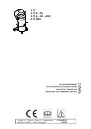
1.2 - Parti principali<br />
(fig. 1.2.1)<br />
Per meglio comprendere la terminologia<br />
utilizzata nel presente<br />
manuale, si richiamano le parti<br />
principali.<br />
A81<br />
1 - Pomello di scuotimento fil<br />
tro<br />
2 - Cappello o coperchio del<br />
gruppo filtro<br />
3 - Filtro primario in materiale<br />
sintetico<br />
4 - Silenziatore di scarico aria<br />
filtrata<br />
5 - Manometro di controllo intasamento<br />
filtro<br />
6 - Contenitore di recupero<br />
detriti<br />
7 - Telaio di base<br />
8 - Ruote piroettanti dotate di<br />
freno di blocco<br />
9 - Motore elettrico di aspirazione<br />
<strong>10</strong> - Quadro elettrico<br />
11 - Plancia porta accessori<br />
12 - Tubo di collegamento<br />
1.2 - Main parts (fig.<br />
1.2.1)<br />
The following list of main parts<br />
will help users to understand the<br />
terms used in this manual.<br />
1.2 - Parties principales<br />
(fig. 1.2.1)<br />
Pour faciliter la compréhension<br />
de la terminologie utilisée dans<br />
ce manuel nous indiquons les<br />
parties principales.<br />
1 - Filter shaking knob 1 - Pommeau de secouage<br />
du filtre<br />
2 - Cap or cover of the filter- 2 - Chapeau ou couvercle du<br />
ing unit<br />
groupe filtre<br />
3 - Primary filter in synthetic 3 - Filtre primaire en matière<br />
material<br />
synthétique<br />
4 - Filtered air exhaust si- 4 - Silencieux d'échappelencerment<br />
de l’air filtré<br />
5 - Pressure gauge to moni- 5 - Manomètre de contrôle de<br />
tor filter clogging<br />
colmatage du filtre<br />
6 - Waste container<br />
6 - Cuve de récupération des<br />
déchets<br />
7 - Base frame<br />
7 - Châssis de base<br />
8 - Castors with brake 8 - Roues pivotantes dotées<br />
de freins de blocage<br />
9 - Electric suction motor 9 - Moteur électrique d’aspiration<br />
<strong>10</strong> - Electric panel<br />
<strong>10</strong> - Tableau électrique<br />
11 - Accessory compartment 11 - Plateau porte-accessoires<br />
12 - Connecting pipe<br />
12 - Tuyau de raccord<br />
-3-<br />
© C.F.M. S.p.A.<br />
Tutti i diritti riservati / All rights reserved<br />
Tous droits réservés / Alle Rechte vorbehalten<br />
1.2 - Hauptteile<br />
(Abb. 1.2.1)<br />
Um die in diesem Handbuch<br />
verwendeten Begriffe besser<br />
verständlich zu machen, werden<br />
die Hauptteile der Maschine<br />
hier aufgeführt.<br />
Fig. 1.2.1<br />
1 - Griff für Filterrüttler<br />
2 - Haube oder Deckel der<br />
Filtergruppe<br />
3 - Hauptfilter aus synthetischem<br />
Material<br />
4 - Schalldämpfer<br />
5 - Manometer zur Anzeige<br />
der Filterbelegung<br />
6 - Abfallbehälter<br />
7 - Untergestell<br />
8 - Lenkrollen mit Bremse<br />
9 - Elektrischer Saugmotor<br />
<strong>10</strong> - Schalttafel<br />
11 - Zubehörfach<br />
12 - Verbindungsschlauch