SWITCH - Foliatec
SWITCH - Foliatec
SWITCH - Foliatec

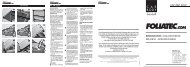
Create successful ePaper yourself
Turn your PDF publications into a flip-book with our unique Google optimized e-Paper software.
<strong>SWITCH</strong><br />
B o a r d<br />
• INSTALLATION INSTRUCTION • MODO D’EMPLOI<br />
C A R S T Y L I N G<br />
STYLINGTEAM<br />
T R E N D W E A R MONTAGEANLEITUNG<br />
INSTRUCCIONES DE MONTAJE • ISTRUZIONI DI APPLICAZIONE
Batterie/Sicherungskasten / Battery/fuse box / Batterie/Coffret à fusibles /<br />
batería/caja de fusibles / Batteria/portafusibili<br />
Ein-/Ausschalter / On/Off switch / interrupteur marche/arrêt / interruptor de<br />
encendido/apagado / interruttore on/off<br />
Kontroll-Lampe/control light/lampe de contrôle/piloto de control/spia<br />
Druckschalter/push switch/interrupteur à pression/interruptor de presión/pulsante<br />
Verbraucher (z.B. Wasserpumpe”BURN-OutKit”)/user (e.g. pump of “BURN-<br />
OutKit”)/récepteur (p. ex. ”BURN-OutKit”)/ dispositivo consumidor (p.ej. ”BURN-<br />
OutKit”)/ utenza (ad es. ”BURN-OutKit”)<br />
empfohlene Einbauposition für Zwischensicherung / Recommended installation position<br />
for safety fuse / Emplacement recommandé pour le montage du fusible de sécurité<br />
/ posición de montaje recomendada para el fusible intermedio / Posizione di<br />
montaggio consigliata per fusibile intermedio
Packungsinhalt: <strong>SWITCH</strong>-Board (mit<br />
Ein-/Ausschalter, Kontroll-Leuchte und<br />
Druckschalter), 4x Montageschrauben<br />
Sie benötigten zusätzlich: Kabelschuhe,<br />
zweiadriges Lautsprecherkabel<br />
(min. 1,5mm 2 , max. 2,5mm 2 ), Quetschverbinder,<br />
Schrumpfschlauch, Akku-Bohrer,<br />
Bohrer 3mm, diverse Schraubendreher. Für<br />
die Anbringung des Montageloches benötigen<br />
Sie zusätzlich Bohrer (10mm + div.<br />
andere), Stahlfeile oder Kegelfräser<br />
Hinweis: Verwenden Sie nach Möglichkeit<br />
folgende Kabelfarben:<br />
Stromquelle/Strom: rot<br />
Masse: schwarz<br />
Warnhinweise: Um elektrischen<br />
Schlägen und Verletzungen bei der<br />
Montage vorzubeugen, unbedingt die<br />
Massekabel der Fahrzeugbatterie vor der<br />
Montage abklemmen.<br />
Nehmen Sie sich ausreichend Zeit für den<br />
Einbau und lassen Sie den Einbau von einer<br />
Fachwerkstatt überprüfen.<br />
Handwerklich unerfahrenen Kunden empfehlen<br />
wir, den Einbau von einer<br />
Fachwerkstatt vornehmen zu lassen.<br />
Deutsch<br />
Legen Sie einen geeigneten Einbauort<br />
fest. Beachten Sie dabei die<br />
Einbautiefe! Achten Sie auf gute<br />
Erreichbarkeit. Die Zugänglichkeit<br />
anderer Schalter u.ä. darf keinesfalls<br />
eingeschränkt werden.<br />
Bringen Sie das Montageloch in ausreichender<br />
Größe an. Achten Sie darauf,<br />
dass die Platte das Loch vollständig<br />
abdeckt.<br />
Schließen Sie das <strong>SWITCH</strong>-Board provisorisch<br />
entsprechend der Schaltskizze<br />
an und überprüfen Sie die Funktionen.<br />
Bauen Sie das <strong>SWITCH</strong>-Board fest ein.<br />
Achtung: Die stromführenden Kabel<br />
dürfen keinesfalls geknickt oder<br />
gequetscht werden (Kabelbruch, Kurzschlussgefahr).<br />
Sicherheitshinweis: Keine Gewährleistungsansprüche<br />
bei Verpolung, unsachmäßem<br />
Einbau, Manipulation der Bauteile<br />
etc.. An einer geschützten Stelle montieren,<br />
damit eine Beschädigung durch äussere<br />
Einflüsse vermieden wird. <strong>SWITCH</strong>-<br />
Board laufend auf festen Sitz sowie elektrische<br />
Verbindungsanschlüsse kontrollieren.<br />
Beachten Sie unbedingt, dass kein<br />
Kabel gequetscht oder geknickt werden<br />
darf und vor Ab- bzw. Durchscheuern<br />
geschützt wird.
Nennspannung: 12V<br />
Nennstrom Kontroll-Leuchte: 25mA<br />
Belastbarkeit: Druckschalter max. 5A<br />
Die LEDs der Kontroll-Leuchte sind<br />
CE-geprüft. Sie haben eine durchschnittliche<br />
Lebensdauer von<br />
10.000 Stunden<br />
Package content: <strong>SWITCH</strong>-Board (with<br />
On / Off switch, control light and<br />
push switch), 4x mounting screws<br />
You also need: Cable lugs, twin-wire<br />
loudspeaker cable<br />
(min. 1.5 mm Ø, max. 2.5 mm Ø), crimp<br />
connection, shrinkdown plastic tubing,<br />
rechargeable drill, 3 mm drill bit, various<br />
screwdrivers. To drill the mounting hole you<br />
also need additional drill bits (10 mm and<br />
others), steel file or beveled cutter.<br />
Note: If possible use the following colors<br />
for wiring<br />
Power source / current: red<br />
Ground: black<br />
Safety precaution: To prevent electrical<br />
shocks and injury during installation it is<br />
essential to disconnect the ground cable<br />
from the battery of the vehicle prior to<br />
installation.<br />
Allow sufficient time for installation and<br />
have the installation checked by qualified<br />
workshop. Customers inexperienced in<br />
crafting should authorize a qualified workshop<br />
with the installation.
English<br />
Determine a suitable location for installation.<br />
Take the necessary installation<br />
depth into consideration! Also take<br />
note of easy accessibility. Do not<br />
impede access to other switches or<br />
instruments.<br />
Bore out the mounting hole to size.<br />
Make sure that the plate completely<br />
covers the hole.<br />
Connect the <strong>SWITCH</strong>-Board temporarily<br />
according to the wiring diagram and<br />
test the functions.<br />
Permanently install the <strong>SWITCH</strong>-Board.<br />
Caution: Make sure that the power<br />
lead cables are not buckled or crimped<br />
in their placement (cable breakage or<br />
danger of short circuit).<br />
Safety instructions: Reverse battery<br />
connection, improper installation, manipulation<br />
of components, etc. can constitute a<br />
danger and will void any and all warranty<br />
claims. Mount at a protected location so<br />
that damages through external influence<br />
are avoided. Check the <strong>SWITCH</strong>-Board<br />
to assure a secure fit as well as the electrical<br />
connections on a regular basis. Take<br />
special care that none of the cables are pinched<br />
or buckled and are protected from chafing<br />
or breakage.<br />
Rated voltage: 12V<br />
Rated current control lamp: 25mA<br />
Load capacity: Push switch max. 5A<br />
The LEDs of the control light are<br />
CE-tested. They have an average<br />
lifespan of 10,000 hours.
Contenu de l’emballage: <strong>SWITCH</strong>-<br />
Board (avec interrupteur marche/arrêt,<br />
lampe de contrôle et interrupteur à pression),<br />
4x vis de fixation<br />
Vous nécessitez en outre: de cosses<br />
de câble, d’un câble haut-parleur bifilaire<br />
(min. 1,5mm 2 , max. 2,5mm 2 ), d’une<br />
pince à sertir, d’une gaine thermorétractable,<br />
d’une perceuse accu, d’une mèche<br />
3mm, de divers tournevis. Pour le perçage<br />
de l’orifice de montage, vous avez de plus<br />
besoin de mèches (10mm + diverses autres),<br />
d’une lime en acier ou d’une fraise<br />
conique<br />
Remarque: : Utilisez si possible les couleurs<br />
de câbles suivantes:<br />
Source de courant/courant: rouge<br />
Terre: noir<br />
Remarque de sécurité: pour éviter<br />
chocs électriques et blessures lors du montage,<br />
veuillez impérativement débrancher<br />
les câbles terre de la batterie du véhicule<br />
avant montage.<br />
Prenez votre temps et faites vérifier le montage<br />
par un atelier spécialisé.<br />
Nous recommandons aux clients peu<br />
expérimentés de confier la pose à un spécialiste.<br />
Français<br />
Choisissez un endroit approprié pour le<br />
montage. Veillez à avoir une profondeur<br />
de montage suffisante! Veillez à<br />
une bonne accessibilité. L’accès à<br />
d’autres interrupteurs p. ex. ne doit en<br />
aucun cas être empêché.<br />
Percez un orifice de montage de grandeur<br />
suffisante. Veillez à ce que la plaque<br />
recouvre entièrement le trou.<br />
Effectuez un raccordement provisoire<br />
du <strong>SWITCH</strong>-Board selon le schéma<br />
électrique et vérifiez les fonctions.<br />
Encastrez fermement le <strong>SWITCH</strong>-<br />
Board.<br />
Attention: les câbles conducteurs ne<br />
doivent en aucun cas être pliés ou<br />
écrasés (risque de rupture de câble, de<br />
court-circuit).<br />
Instructions de sécurité: aucun droit<br />
à la garantie en cas d’inversion de polarité,<br />
montage incorrect, manipulation des composants,<br />
etc. Monter à un endroit protégé<br />
pour éviter tout dommage par suite d’influences<br />
extérieures. Toujours contrôler la<br />
bonne position des <strong>SWITCH</strong>-Board ainsi<br />
que les raccordements électriques. Ne<br />
jamais plier ou coincer de câble. Protéger<br />
contre tout frottement et usure
Tension nominale: 12V<br />
Courant nominal lampe de contrôle:<br />
25mA<br />
Intensité maximale interrupteur à pression:<br />
5A<br />
Les LEDs de la lampe de contrôle<br />
sont homologuées CE. Elles ont<br />
une longévité moyenne de 10.000<br />
heures.
Contenido del paquete: Placa<br />
<strong>SWITCH</strong>-Board (con interruptor de encendido/apagado,<br />
piloto de control e interruptor<br />
de presión), 4 x tornillos de montaje<br />
Además, precisa: terminales para<br />
cables, cable bifilar para altavoces (mín.<br />
1,5 mm 2 , máx. 2,5 mm 2 ), elemento de<br />
unión por apriete, manguera encogible en<br />
caliente, taladradora de batería, broca de 3<br />
mm, diversos atornilladores. Para la colocación<br />
del agujero de montaje, precisará también<br />
una broca (10 mm + otras diversas),<br />
lima de acero o fresa cónica.<br />
Nota: A ser posible, emplee los siguientes<br />
colores de cables:<br />
Fuente de alimentación de corriente/corriente:<br />
rojo<br />
Masa: negro<br />
Advertencias: A fin de prevenir las descargas<br />
eléctricas y lesiones durante el montaje,<br />
es imprescindible desembornar los<br />
cables de masa de la batería del vehículo,<br />
antes de proceder al montaje.<br />
No vaya con prisas a la hora de realizar el<br />
montaje y hágalo revisar por un taller especializado.<br />
A los clientes sin experiencia en la ejecución<br />
de trabajos manuales, les recomendamos<br />
que hagan efectuar el montaje por un<br />
taller especializado.<br />
Español<br />
Determine un lugar de montaje adecuado.<br />
¡Tenga en cuenta, el fondo de<br />
montaje a la hora de elegir el lugar!<br />
Así, también tenga en cuenta el acceso.<br />
En ningún caso, debe quedar entorpecida<br />
la accesibilidad a otros interruptores<br />
y similares.<br />
Haga un agujero de montaje con un<br />
tamaño adecuado. A tal efecto, vigile<br />
que la placa cubra el agujero por completo.<br />
Conecte el <strong>SWITCH</strong>-Board de manera<br />
provisional según el esquema de conexiones<br />
y compruebe el funcionamiento.<br />
Monte el <strong>SWITCH</strong>-Board de forma fija.<br />
Atención: Bajo ningún concepto, los<br />
cables bajo tensión deben quedar doblados<br />
o aprisionados (rotura de cable,<br />
peligro de cortocircuito).<br />
Advertencias de seguridad: No<br />
habrá derecho a las prestaciones de la<br />
garantía en caso de polarización inversa,<br />
montaje inadecuado, manipulación de las<br />
piezas, etc. Efectúe el montaje en un lugar<br />
protegido para evitar daños por factores<br />
externos. Debe comprobar de forma constante<br />
los <strong>SWITCH</strong>-Board de cara a su<br />
apriete firme así como las conexiones eléctricas<br />
de enlace. Observe sin falta que no<br />
se debe doblar ni dejar aprisionado ningún
cable y que éstos deben estar protegidos<br />
contra el desgaste por rozadura y la perforación<br />
por rozadura.<br />
Tensión nominal: 12V<br />
Corriente nominal piloto de control:<br />
25mA<br />
Cargabilidad: Interruptor de presión<br />
máx. 5A<br />
Los diodos LED del piloto de control<br />
están comprobados de cara a<br />
la CE. La vida útil media de los<br />
diodos es de 10.000 horas.<br />
Contenuto della confezione:<br />
<strong>SWITCH</strong>-Board (con interruttore on/off,<br />
spia epulsante), 4 viti di montaggio<br />
Sono inoltre necessari: ancoraggi per<br />
cavi, cavo per altoparlante a due fili (min.<br />
1,5 mm 2 , max. 2,5 mm 2 ), capocorda a<br />
pressione, tubo termoretraibile, trapano a<br />
batteria, punta da trapano da 3 mm, vari<br />
cacciaviti. Per praticare il foro di montaggio,<br />
sono inoltre necessarie altre punte (da 10<br />
mm + diverse altre), lima d’acciaio o fresa<br />
conica.<br />
Nota: a seconda delle possibilità, utilizzare<br />
i seguenti colori dei cavi:<br />
fonte di corrente/corrente: rosso<br />
massa: nero<br />
Avvertenze: per evitare scosse elettriche<br />
e lesioni durante il montaggio, staccare<br />
assolutamente i cavi di massa della batteria<br />
del veicolo prima del montaggio.<br />
Procedere con adeguata attenzione al montaggio<br />
e farlo controllare da un’officina specializzata.<br />
Consigliamo ai clienti meno esperti di far<br />
eseguire il montaggio da parte di un’officina<br />
specializzata.
Italiano<br />
Stabilire una posizione di montaggio<br />
adeguata. A questo proposito, osservare<br />
la profondità di montaggio!<br />
Assicurare una buona raggiungibilità.<br />
L’accessibilità ad altri interruttori e<br />
similari non deve essere limitata in<br />
nessun caso.<br />
Praticare un foro di montaggio di<br />
dimensioni sufficienti. Assicurarsi che<br />
la piastra copra completamente il foro.<br />
Collegare provvisoriamente la <strong>SWITCH</strong>-<br />
Board come illustrato nello schizzo di<br />
collegamento e controllare le funzioni.<br />
Fissare poi la <strong>SWITCH</strong>-Board.<br />
Attenzione: i cavi che conducono corrente<br />
non devono essere piegati o<br />
schiacciati in nessun caso (rottura dei<br />
cavi, pericolo di cortocircuiti).<br />
Avvertenze di sicurezza: nessun diritto<br />
di garanzia in caso di inversione della<br />
polarità, montaggio errato, manipolazione<br />
dei componenti, ecc. Montare in un luogo<br />
protetto per evitare un danneggiamento<br />
dovuto a fattori esterni. Controllare costantemente<br />
che la sede dei <strong>SWITCH</strong>-Board<br />
sia corretta e i collegamenti elettrici. Non<br />
schiacciare o piegare assolutamente nessun<br />
cavo e proteggere i cavi nei confronti di<br />
abrasioni e sfregamenti.<br />
Tensione nominale: 12 V<br />
Corrente nominale spia: 25 mA<br />
Carico ammissibile: pulsante max. 5A<br />
I LED della spia recano il marchio<br />
CE ed hanno una durata media di<br />
10.000 ore.
Diese Montageanleitung kann auf Grund technischer Änderungen durch eine<br />
neue Version ersetzt worden sein. Bitte informieren Sie sich auf unserer Website<br />
www.foliatec.de, ob es sich bei der vorliegenden Anleitung um die neueste<br />
Version handelt. Informationen zu FOLIA TEC Produkten sowie Tipps und Tricks<br />
zur Montage finden Sie in unserem Internet-Technik-Forum unter<br />
www.foliatec.de.<br />
Oder fragen Sie unser Technik-Team (Tel. +49/(0)911/975440)<br />
These operating instructions may have been replaced with a newer version due<br />
to technical changes. Visit our website at www.foliatec.de to see if the instructions<br />
provided represent the latest version. Information on FOLIA TEC products<br />
as well as installation tips and tricks can be found in our Internet-Technique-<br />
Forum under www.foliatec.com.<br />
Or contact our technical team (Tel. +49 (0)911-97 54 40).<br />
Copyright© by FOLIA TEC. All rights reserved. Verstöße werden gerichtlich verfolgt.<br />
Violators will be prosecuted to the full extent of the law. FOLIA TEC® is an int. reg.<br />
TM of FOLIA TEC Böhm GmbH + Co.Vertriebs KG, Germany. Druckfehler, Irrtum und<br />
technische Änderungen vorbehalten. Subject to misprints, errors and technical changes.<br />
FOLIA TEC® Carstyling<br />
Neumeyerstraße 70 • 90411 Nürnberg • GERMANY<br />
Tel. +49/(0)911/97544-0 • Fax +49/(0)911/97544333<br />
E-mail: techsupport@foliatec.de<br />
Stand 12/04


![DOWNLOAD: Zulassungsbestimmungen [PDF/ 1,5 MB] - Foliatec](https://img.yumpu.com/21056384/1/184x260/download-zulassungsbestimmungen-pdf-15-mb-foliatec.jpg?quality=85)