Model AV1-LED Audio-Visual LED Light - Federal Signal
Model AV1-LED Audio-Visual LED Light - Federal Signal Model AV1-LED Audio-Visual LED Light - Federal Signal
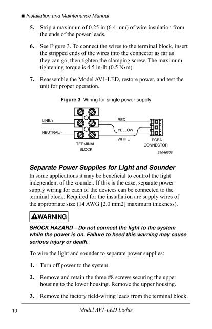
10 ■ Installation and Maintenance Manual 5. Strip a maximum of 0.25 in (6.4 mm) of wire insulation from the ends of the power leads. 6. See Figure 3. To connect the wires to the terminal block, insert the stripped ends of the wires into the connector as far as they can go, then tighten the clamping screw. The maximum tightening torque is 4.5 in-lb (0.5 N•m). 7. Reassemble the Model AV1-LED, restore power, and test the unit for proper operation. LINE/+ NEUTRAL/− Figure 3 Wiring for single power supply TERMINAL BLOCK RED YELLOW WHITE Model AV1-LED Lights PCBA CONNECTOR 290A6506 Separate Power Supplies for Light and Sounder In some applications it may be beneficial to control the light independent of the sounder. If this is the case, separate power supply wiring for each of the devices can be connected to the terminal block. Required for the installation are supply wires of the appropriate size (14 AWG [2.0 mm2] maximum thickness). SHOCK HAZARD—Do not connect the light to the system while the power is on. Failure to heed this warning may cause serious injury or death. To wire the light and sounder to separate power supplies: 1. Turn off power to the system. 2. Remove and retain the three #8 screws securing the upper housing to the lower housing. Remove the upper housing. 3. Remove the factory field-wiring leads from the terminal block.
Installation and Maintenance Manual ■ 4. Route separate supply wires of the appropriate gauge for the light and sounder into the housing through the conduit entry. 5. Strip a maximum of 0.25 in (6.4 mm) of wire insulation from the ends of the power leads. 6. See Figure 4. To connect the wires to the terminal block, insert the stripped ends of the wires into the connector as far as they can go, then tighten the clamping screw. The maximum tightening torque is 4.5 in-lb (0.5 N•m). NOTE: If it is necessary to combine two NEUTRAL/– wires, connect them to the same terminal on the terminal block. 7. Reassemble the Model AV1-LED, restore power, and test the unit for proper operation. LINE/+ (SOUNDER) LINE/+ (LIGHT) NEUTRAL/− Figure 4 Wiring for separate power supplies RED YELLOW WHITE PCBA CONNECTOR 290A6507 Model AV1-LED Lights 11
- Page 1 and 2: 2561528A REV. A 512 Printed in U.S.
- Page 3 and 4: Contents Safety Messages to Install
- Page 5 and 6: Installation and Maintenance Manual
- Page 7 and 8: Installation and Maintenance Manual
- Page 9: Installation and Maintenance Manual
- Page 13 and 14: Installation and Maintenance Manual
- Page 15 and 16: Replacing the Sounder Installation
- Page 17 and 18: Installation and Maintenance Manual
- Page 19 and 20: Installation and Maintenance Manual
- Page 21 and 22: DEL audio-visuelle modèle AV1 Manu
- Page 23 and 24: Table des matières Messages de sé
- Page 25 and 26: Manuel d’installation et d’entr
- Page 27 and 28: Manuel d’installation et d’entr
- Page 29 and 30: Manuel d’installation et d’entr
- Page 31 and 32: Manuel d’installation et d’entr
- Page 33 and 34: Manuel d’installation et d’entr
- Page 35 and 36: Manuel d’installation et d’entr
- Page 37 and 38: Manuel d’installation et d’entr
- Page 39 and 40: Tableau 2 Pièces de rechange Manue
- Page 41 and 42: Modelo AV1-LED Luz LED audiovisual
- Page 43 and 44: Contenido Mensajes de seguridad par
- Page 45 and 46: Installation and Maintenance Manual
- Page 47 and 48: Installation and Maintenance Manual
- Page 49 and 50: Installation and Maintenance Manual
- Page 51 and 52: Installation and Maintenance Manual
- Page 53 and 54: Installation and Maintenance Manual
- Page 55 and 56: Reemplazo de la sirena Installation
- Page 57 and 58: Installation and Maintenance Manual
- Page 59 and 60: Installation and Maintenance Manual
10<br />
■ Installation and Maintenance Manual<br />
5. Strip a maximum of 0.25 in (6.4 mm) of wire insulation from<br />
the ends of the power leads.<br />
6. See Figure 3. To connect the wires to the terminal block, insert<br />
the stripped ends of the wires into the connector as far as<br />
they can go, then tighten the clamping screw. The maximum<br />
tightening torque is 4.5 in-lb (0.5 N•m).<br />
7. Reassemble the <strong>Model</strong> <strong>AV1</strong>-<strong>LED</strong>, restore power, and test the<br />
unit for proper operation.<br />
LINE/+<br />
NEUTRAL/−<br />
Figure 3 Wiring for single power supply<br />
TERMINAL<br />
BLOCK<br />
RED<br />
YELLOW<br />
WHITE<br />
<strong>Model</strong> <strong>AV1</strong>-<strong>LED</strong> <strong>Light</strong>s<br />
PCBA<br />
CONNECTOR<br />
290A6506<br />
Separate Power Supplies for <strong>Light</strong> and Sounder<br />
In some applications it may be beneficial to control the light<br />
independent of the sounder. If this is the case, separate power<br />
supply wiring for each of the devices can be connected to the<br />
terminal block. Required for the installation are supply wires of<br />
the appropriate size (14 AWG [2.0 mm2] maximum thickness).<br />
SHOCK HAZARD—Do not connect the light to the system<br />
while the power is on. Failure to heed this warning may cause<br />
serious injury or death.<br />
To wire the light and sounder to separate power supplies:<br />
1. Turn off power to the system.<br />
2. Remove and retain the three #8 screws securing the upper<br />
housing to the lower housing. Remove the upper housing.<br />
3. Remove the factory field-wiring leads from the terminal block.


