Bedienungsanleitung Katzpuffer - Heidkamp Hebezeuge
Bedienungsanleitung Katzpuffer - Heidkamp Hebezeuge
Bedienungsanleitung Katzpuffer - Heidkamp Hebezeuge

Create successful ePaper yourself
Turn your PDF publications into a flip-book with our unique Google optimized e-Paper software.
Anweisung für Montage und Betrieb<br />
Instructions for assembly and operating<br />
Instruction de montage et de service<br />
UNI-<strong>Katzpuffer</strong><br />
UNI-END BUFFER<br />
Butées UNI<br />
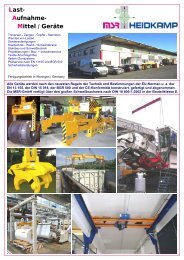
Der ideale Katzfahr-Endanschlag geeignet für Hand- und Elektrofahrwerke<br />
aller Fabrikate bis 10000 kg<br />
The ideal Trolley Travel End Stop suitable for manual and electric trolleys<br />
all makes up to 10000 kg<br />
La idéal Butée de direction approprié pour chariots manuels et électriques<br />
toutes les marques à 10000 kg<br />
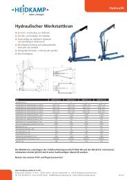
Einsatztabelle / Table range / Table d`utilisation<br />
Tragfähigkeit max. zulässige max. zulässige<br />
Hebezeuggewicht Anfahrgeschwindigkeit<br />
Capacity Max. hoist weight Max. trolley speed<br />
Force Poids max. du palan Adm. Vitesse du chariot<br />
125 bis 2000 kg 180 kg 28 m/min<br />
2500 kg 225 kg 25 m/min<br />
3200 kg 225 kg 22 m/min<br />
4000 kg 325 kg 20 m/min<br />
5000 kg 600 kg 16 m/min<br />
6300 kg 600 kg 14 m/min<br />
8000 kg 1500 kg 12 m/min<br />
10000 kg 1500 kg 10 m/min<br />
_________________________________________________________________________________<br />
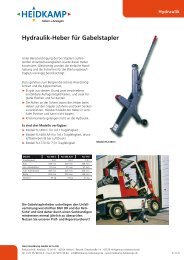
Variante A<br />
Alternative A<br />
La variante A<br />
2 3<br />
2 6 5 7 8<br />
7 5 6 1 4 7,5,6 1<br />
_________________________________________________________________________________<br />
8<br />
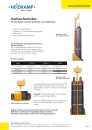
Variante B<br />
Alternative B<br />
La variante B<br />
7 5 6 1 4 7,5,6 1<br />
2 3<br />
2 6 5 7<br />
MB_Uni-<strong>Katzpuffer</strong>_DE_EN_FR07.13
UNI-<strong>Katzpuffer</strong> UNI-END BUFFER Butées UNI<br />
Katzfahr-Endanschlag Trolley Travel End Stop Butée de direction<br />
Montage- und<br />
Betriebsanleitung<br />
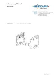
Achtung!<br />
Die keilförmigen Klemmstücke (Pos. 2) müssen<br />
in der dargestellten Einbaulage zum<br />
Profilträger eingebaut werden. Keinesfalls ist<br />
eine andere Einbaulage zu wählen, da dann<br />
keine Klemmwirkung entsteht.<br />
Sämtliche verwendeten Teile sind verzinkt, die<br />
Rahmenbleche und Klemmstücke zusätzlich<br />
passiviert und benötigen keinen weiteren<br />
Korrosionsschutz.<br />
1. Auf die Gewindestange (4) jeweils bis zur<br />
Mitte 2 Sicherungsmuttern (7), 2 Muttern<br />
(5) und 2 Scheiben (6) aufschrauben. Auf<br />
gleichmäßige Verteilung rechts und links<br />
achten.<br />
2. Beide Rahmenbleche (1) rechts und links,<br />
wie gezeichnet, auf die Gewindestange<br />
(4) stecken und in das Trägerprofil<br />
schieben.<br />
3. Jeweils 2 Klemmstücke (2) von außen auf<br />
die Gewindestange (4) schieben und mit<br />
Scheiben (6), Muttern (5) und<br />
Sicherungsmuttern (7) von Hand<br />
gegenziehen.<br />
4. Die Gummipuffer (3) an der Stelle<br />
befestigen, wo möglichst Rahmen oder<br />
Traverse des <strong>Hebezeuge</strong>s anschlagen.<br />
Hierfür sind mehrere Varianten<br />
vorgesehen.<br />
5. Die UNI-<strong>Katzpuffer</strong> auf Trägerprofil soweit<br />
verschieben, dass der Nennfahrbereich<br />
nicht überschritten wird.<br />
Jedoch ist ein Mindestabstand von 10<br />
mm bis zum Profilende einzuhalten.<br />
6. Die äußeren Muttern (5) von beiden<br />
Seiten gleichmäßig anziehen. Darauf<br />
achten, dass die Rahmenbleche (1) mit<br />
ihren Anlageflächen am Trägerrand<br />
anliegen.<br />
7. Die innenliegenden Muttern (5) zum<br />
Rahmenblech (1) hin leicht gegenziehen.<br />
8. Die äußeren Muttern (5) mit einem<br />
Drehmoment von 35 Nm (3,5 kpm)<br />
anziehen und durch die<br />
Sicherungsmuttern (7) kontern.<br />
9. Wie vor, die inneren Muttern (5) mit<br />
gleichem Drehmoment anziehen und<br />
kontern.<br />
10. Überstehende Gewindestange (4), falls<br />
erforderlich, absägen.<br />
11. Probeweise das Hebezeug gegen den<br />
<strong>Katzpuffer</strong> fahren. ACHTUNG! Der<br />
<strong>Katzpuffer</strong> ist ein Anschlag und muss<br />
regelmäßig auf festen Sitz hin überprüft<br />
werden. Nach Bedarf, spätestens jedoch<br />
nachdem eine Verschiebung erfolgte,<br />
muss eine neue Befestigung erfolgen.<br />
Eignung ausschließlich für<br />
parallelflanschige Trägerprofile mit<br />
Flanschdicken von 8 – 25 mm, Trägerbreiten<br />
von 91 bis 300 mm, Tragfähigkeiten<br />
bis 10.000 kg und Fahrgeschwindigkeiten<br />
bis 28 m/min. (siehe Einsatztabelle)<br />
Wenn bei Versagen des <strong>Katzpuffer</strong>s Personen<br />
gefährdet werden können, ist eine zusätzliche<br />
Sicherung (8) notwendig. (Kann auch ein<br />
Endblech sein)<br />
Assembly and<br />
operating instruction<br />
Important!<br />
The wedge-shaped clamping pieces (pos. 2) have<br />
to be located to the rolled-steel section as shown.<br />
Do not choose a different installing position as than<br />
there is no clamping function.<br />
Varous items of the end stop are zinc plated, the<br />
side plates and clamping piece are passivated and<br />
require no further corrosion protection.<br />
1. On the threaded rod (4), install towards the<br />
middle 2 x safety nuts (7), 2 x nuts (5) and 2 x<br />
washers (6) – qual distance in from each end.<br />
2. Locate the end plate (1) right and left on the<br />
threaded rod (4) as shown and install on the<br />
beam flange.<br />
3. Install on the threaded rod (4) 2 clamping<br />
pieces (2) from the outside. The install<br />
washers (6) nuts (5) and lock nuts (7) and do<br />
up hand tight.<br />
4. Install the rubber buffer (3) in the position<br />
where it is best suited to absorb the shock of<br />
the hoist trolley hitting against the end stop –<br />
there are some holes for variations available.<br />
5. Slide the “end stop” along the rolled steel<br />
section of the jib so that the capacity of the<br />
crane is not exceeded.<br />
Ensure that a minimum of 10 mm is<br />
allowed between the end stop and the jib.<br />
6. Do up the outside nuts (5) on both sides at the<br />
same time ensuring that the side plates (1)<br />
are in contact with the rolled beam.<br />
7. Gently tighten the inner nuts (5) against the<br />
side plates (1).<br />
8. Torque up the outer nuts (5) with 35 Nm (3.5<br />
kpm) and finally tighten the lock nuts (7).<br />
9. Torque up the inner nuts (5) with 35 Nm (3.5<br />
kpm) and finally tighten the lock nuts (7).<br />
10. Remove that portion of the threaded rod (4)<br />
that is too long.<br />
11. Drive the hoist against the end stop to ensure<br />
it is secure. ATTENTION! The end stop is a<br />
safety device and must be constantly checked<br />
to ensure it has not removed. As required but<br />
at least when the end stop is pushed to the<br />
end of the jib it must be reinstalled.<br />
Designed only for parallel flange beams with<br />
flange thickness of 8 to 25 mm, beam breadth of<br />
91 to 300 mm, capacity up to 10.000 kg and<br />
maximum travel speed of 28 m/min. (see table<br />
range).<br />
If persons could be endangered in the case of<br />
failure of the buffer, additional protections become<br />
necessary. (Can also be an end plate)<br />
Instruction de<br />
montage et de service<br />
Attention!<br />
Les pièces de serrage en forme de coins (pos. 2)<br />
doivent être mises en place conformément à la<br />
positon représentée par rapport au profilé support.<br />
Il ne faudra en aucun cas adopter une autre<br />
position, car il n’y aurait alors plus aucun effet de<br />
serrage.<br />
La totalité des pièces utilisées sont galvanisées,<br />
les deux tôles-cadre et les coins sont, en sus,<br />
passivés et ne requièrent pas d’autre protection<br />
contre la corrosion.<br />
1. Visser sur la tige filetée (4), jusqu’au milieu,<br />
respectivement, 2 contre-écrous (7), 2<br />
écrous (5) et 2 rondelles (6). Veiller à ce<br />
qu’ils soient symétriques à gauche et à<br />
droite.<br />
2. Placer les deux tôles-cadre (1), à droite et à<br />
gauche, comme représenté dans le<br />
schéma, sur la tige filetée (4) et enfoncer<br />
dans le profilé support.<br />
3. Mettre en place 2 coins (2) sur la tige filetée<br />
(4) par I’extérieur et visser à la main avec<br />
les rondelles (6), lex écrous (5) et les<br />
contre-écrous (7).<br />
4. Les tampons amortisseurs (3) doivent étre<br />
placés de manière à buter le mieux<br />
possible le cadre ou la traverse du palan.<br />
Plusieurs variates sont prévues à cet effet.<br />
5. Faire glisser les butées UNI sur le profilé<br />
support de sorte que le rayon d’action<br />
nominal ne soit pas dépassé.<br />
Il faudra toutefois respecter un ecart<br />
minimum de 10 mm par rapport à<br />
I’extremite du profile.<br />
6. Serre de la même manière les écrous<br />
extérieurs (5) de chaque côté. Veiller à ce<br />
que les surfaces d’appui des tôles-cadre (1)<br />
soient bien affleurées sur le bord du<br />
support.<br />
7. Serre légèrement les écrous intérieurs (5)<br />
contre la tôle-cadre (1).<br />
8. Serrer les écrous extérieurs (5) avec un<br />
couple de 35 Nm (3,5 mkg). Serrer les<br />
contre-écrous (7).<br />
9. Comme précédemment, serrer les écrous<br />
intérieurs (5) avec le même couple et serrer<br />
les contre-écrous.<br />
10. Scier I’extrémité de la tige filetée (4) qui se<br />
trouve en saillie, si nécessaire.<br />
11. Faire un essai du palan sur les butées.<br />
ATTENTION! La butée est une pièce de<br />
sécurité et il faudra s’assurer régulièrement<br />
qu’elle n’ait pas de jeu. Selon les besoins,<br />
mais au plus tard, toutefois, après que I’on<br />
ait constraté un décalage, il faudra<br />
procéder à une nouvelle fixation.<br />
Approprié uniquement pour les profilés<br />
support à ailes parallèles avec épaisseur<br />
d’aile de 8 – 25 mm, largeur de support de 91<br />
à 300 mm, charge maxi admissible 10.000 kg<br />
et vitesse maxi de 28 m/min. (voir table<br />
d’utilisation).<br />
Si des personnes risquend d’être mis en danger<br />
au cas de panne de butée, d’autres protections<br />
sont nécessaires. (Peut aussi être une plaque<br />
terminale)<br />
MB_Uni-<strong>Katzpuffer</strong>_DE_EN_FR07.13